EVDI产品部署及运维手册cn
爱维云使用手册说明书
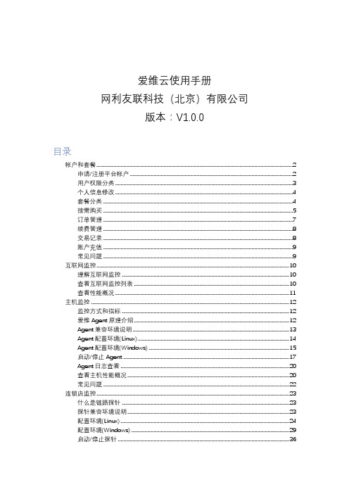
爱维云使用手册网利友联科技(北京)有限公司版本:V1.0.0目录帐户和套餐 (2)申请/注册平台帐户 (2)用户权限分类 (3)个人信息修改 (4)套餐分类 (4)按需购买 (5)订单管理 (7)续费管理 (8)交易记录 (8)账户充值 (9)常见问题 (9)互联网监控 (10)理解互联网监控 (10)查看互联网监控列表 (10)查看性能概况 (11)主机监控 (12)监控方式和指标 (12)爱维Agent原理介绍 (12)Agent兼容环境说明 (13)Agent配置环境(Linux) (14)Agent配置环境(Windows) (15)启动/停止Agent (17)Agent日志查看 (20)查看主机性能概况 (20)常见问题 (22)连锁店监控 (23)什么是链路探针 (23)探针兼容环境说明 (23)配置环境(Linux) (24)配置环境(Windows) (29)启动/停止探针 (36)探针日志查看 (39)查看链路探针列表 (39)添加监控 (40)批量导入 (44)查看监控设备性能概况 (45)采集时间表 (46)内网监控 (48)监控方式与监控内容 (48)爱维内网工具下载 (48)兼容环境说明 (49)安装说明(Linux) (49)安装说明(Windows) (52)启动/停止内网监控工具 (56)登录爱维内网工具 (57)操作手册下载 (58)业务视图 (59)理解业务视图 (59)查看业务趋势 (59)查看业务视图 (60)告警管理 (61)告警状态说明 (61)告警列表 (62)告警通知设置 (63)微信告警 (64)通过url发送告警 (67)数据源 (69)创建数据源 (69)zabbix接入 (70)成员/成员组 (75)报告管理 (76)邮件报告 (76)帐户和套餐申请/注册平台帐户可申请注册的帐户类型系统平台支持个人用户的注册,及服务商用户的申请个人用户注册您可以点击注册按钮后,点击个人用户注册,提交表单后,会向您的注册邮箱发送激活链接,激活后即可登录系统平台官网。
步步高evd影碟机说明书

步步高evd影碟机说明书摘要:1.步步高EVD 影碟机简介2.产品特点3.安装与连接4.操作方法5.维护与保养6.故障排除与售后服务正文:【步步高EVD 影碟机简介】步步高EVD 影碟机是一款高品质的影碟播放设备,可以播放各种DVD、VCD 和CD 光盘。
它具有卓越的图像和音频质量,是家庭娱乐的理想选择。
【产品特点】步步高EVD 影碟机具有以下特点:1.高品质的图像和音频质量,让用户享受真正的家庭影院体验。
2.兼容性强,可以播放各种DVD、VCD 和CD 光盘。
3.具有多种功能,如快进、快退、暂停等,方便用户进行操作。
4.设计人性化,操作简单易懂,适合各个年龄段的用户使用。
【安装与连接】安装步步高EVD 影碟机非常简单,只需按照以下步骤进行:1.将影碟机放在平稳的地面上,并确保其周围有足够的空间。
2.将电源线插入影碟机的电源插座,并连接到电源插座。
3.将影碟机与电视或音响设备连接,可以使用HDMI 线或AV 线。
4.开启影碟机和电视或音响设备,调整它们到正确的输入模式。
【操作方法】步步高EVD 影碟机的操作非常简单,用户只需按照以下步骤进行:1.将光盘放入影碟机中,并按下“播放”键。
2.使用遥控器或机身按钮进行快进、快退、暂停等操作。
3.通过菜单键调整图像、音频和字幕等设置。
4.在播放过程中,用户可以根据需要随时暂停、停止或重新开始。
【维护与保养】为了确保步步高EVD 影碟机的正常运行和延长使用寿命,用户需要进行以下维护和保养工作:1.定期清洁影碟机,特别是进出盘仓和按键部分。
2.使用正宗的光盘,避免使用损坏或质量差的光盘。
3.在使用过程中,避免强烈震动和阳光直射。
4.长时间不使用时,应将影碟机关闭并断开电源。
【故障排除与售后服务】如果在使用过程中遇到问题,用户可以尝试以下方法进行故障排除:1.检查电源线是否接触良好,电源插座是否正常工作。
2.更换光盘,看看是否是光盘的问题。
3.重新启动影碟机,看看问题是否解决。
运维工作指导手册(目录框架)
运维工作指导手册
一、资源和业务规划及申请
1、项目计划书模板
2、背景和业务目标规划
3、组织和人力资源规划
4、硬件资源规划
5、业务规划
6、财务预算
二、组织和人力资源管理
1、管理职责
2、设置组织机构(成立、任命、部门手册、岗位职责)
3、人力资源招聘
4、入职培训和转正
5、薪酬待遇
6、绩效考核
7、人才培养和团队建设
三、财务和行政资源管理
1、管理职责
2、硬件资源配置
3、费用和报销管理
4、财务统计和核算
四、其他工作管理
1、作息制度
2、工作计划和汇报制度
3、固定资产低值易耗品管理
4、工具管理
5、备品备件和耗材管理
6、实验室管理
7、数据监控中心管理
8、档案室管理
9、收入管理
五、设备和基站移交
1、排查
2、检测
3、比对验收
4、设备整改和更换
5、交接
六、签订合同和新建、更换设备
1、明确建设要求
2、签定合同
3、新建和更换设备
七、运营
1、确定运营目标和要求,制定工作流程和制度
2、制定巡检计划并执行
3、确定数据监控计划并执行
4、确定维修和故障处理计划并执行
5、确定数据和工作报告计划并执行
6、确定关系维护计划并执行
八、附录流程和规章制度。
EVDevo手册

5. 控制
18
5.1 主控制和辅助控制 ............................................................................... 18 5.2 过热度控制................................................................................................ 18 5.3 特殊控制..................................................................................................... 19 5.4 辅助控制 ....................................................................................................22
康和环境带来负面影响; 4. 设备、包装或说明单上显示的符号(打叉带轮垃圾桶)表示设备已
于2005年8月13日之后投放市场,并且表示必须分开弃置; 5. 如果非法弃置电气电子废物,将按照当地废物弃置法规进行处罚。
材料质保:2年L S.P.A.已通过 ISO 9001设计和生产系统认证,产品的质量 和安全都有保障,带有标记。
腐蚀性矿物质,可能会损坏电子电路。无论如何,应当在符合手册 规定的温湿度限值的环境中使用或储存该产品。 • 不得将设备安装在特别热的环境中。温度太高可能会缩短电子设备 的使用寿命、损坏它们、并使塑料部件变形或熔化。无论如何,应 当在符合手册规定的温湿度限值的环境中使用或储存产品。 • 不得试图以非本手册规定的方法打开设备。 • 不得坠落、撞击或摇晃设备,因为内部电路和机构可能会受到无法 修复的损伤。 • 不得使用腐蚀性化学品、溶剂或强力清洁剂来清洁设备。 • 不得将产品用于非该技术手册规定的用途。
V200S VERIS Verabar (单杆)安装和维护手册说明书

V200S VERIS Verabar® (Single Rod) Installation and Maintenance Manual169-EN Please read and savethese instructionsContentsGeneral Safety Information (3)Product Information (3)Section 1: Scope (3)Section 2: Receiving and InspectingSection 3: Safety Precautions (3)Section 4: Installation Preparations ......................................................3-5Location (3)Orientation (4)Horizontal Piping (4)Vertical Piping (5)DP Transmitter/Local Indicator Location (5)Installation Drawings and Bill of Materials (5)Piping Support (5)Section 5: Installation Procedure .........................................................6-9Assemble the Verabar® (6)Insert Instrument Vales or Manifold (6)Valves (6)Manifold (6)Retract Sensor and Tighten Packing (7)Weld Thread-o-let to Pipe (7)Install Close Nipple & Access Valve (7)Drill Hole in Pipe (7)Mount Sensor Assembly to Access Valve (8)Vent Access Valve to Verify No Leaks are Present (8)Grease Drive Rod (8)Insert Verabar® Sensor Assembly (8)Orientation of Flow Arrow (9)Section 6: Proper Installation (10)Section 7: Periodic Maintenance (10)Limited Warranty and Remedy (11)2Designs, materials, weights and performance ratings are approximate and subject to change without notice.Visit armstrong for up-to-date information.3Designs, materials, weights and performance ratings are approximate and subject to change without notice.Visit armstrong for up-to-date information.Section 1 ScopeThese instructions provide a description of procedures for installing the V200S (Single Rod) Verabar ® flow sensor. Procedures are given for all industrial flow measurement applications including liquid, steam and gas for both horizontal and vertical piping configurations.Section 2 Receiving InspectionThe following tasks should be performed as part of the receiving inspection procedure:• Check items received against the packing list.• Check sensor nameplate for proper model number, serial number and tag number.• Verify the actual pipe diameter matches the ID stated on the sensor nameplate.• Check the bullet shaped sensor tube for any signs of damage. Damage to the sensor tube may result in erroneous flow readings.• Check the round cover tube for any damage, especially axial gouges or scratches. Damage to the cover tube may prevent the packing from sealing properly.Section 3 Safety PrecautionsThe following process should be conducted prior to installing the Verabar ® flow sensor:• Check the maximum operating conditions on the flow sensor nameplate. If any pressure, temperature or flow limits will be exceeded, contact the factory before proceeding.Section 4 Installation Preparations4.1 LocationFor the most accurate flow measurement, a minimum straight run of pipe is required. Table 1 shows the minimum straight run requirements. If longer straight runs are available, position the Verabar ® such that the ratio of upstream straight run to downstream straight run is approximately 4 to 1. If straight run lengths are less than the values stated in Table 1, contact Armstrong’s VERIS Flow Measurement Group directly. Straightening vanes should be positioned such that the end closest to the Verabar ® is half way between the Verabar ® and the closest upstream configuration. For elbow installations, mount the Verabar ® in the same planeas the closest upstream elbow.General Safety InformationProduct InformationInstructions and procedures listed in this manual may require special precautions to ensure the safety of the individuals performing the operations. Review the entire manual, taking note of safety messages prior to performing any operations listed in the manual.The VERIS Verabar ® averaging pitot flow sensor provides unsurpassed accuracy and reliability. With its solid, one-piece construction and bullet shape the VERIS Verabar ® makes flow measurement reliable and precise.The unique sensor shape reduces drag and flow induced vibration. The location of the low-pressure ports eliminates the potential for clogging and improves signal stability.The V200S model can be inserted and removed from service under pressure. It features a single drive rod and threaded mounting components.4Designs, materials, weights and performance ratings are approximate and subject to change without notice.Visit armstrong for up-to-date information.Table 1. Straight Run Requirements4.2 OrientationVerify the proper sensor orientation by checking for an “-H” (horizontal piping) or a “-V” (vertical piping) in the model number on the Verabar ® name plate. Verify that the flow arrow stamped on the instrument head is pointing downstream in the direction of flow.4.2.1 Horizontal PipingFor air or gas installations, mount the Verabar ® in the upper 160° of the pipe to allow any condensate to draininto the pipe (Figure 1). For liquid or steam installations, mount the Verabar ® in the lower 160° of the pipe. Thisallows any entrained air to bleed back into the pipe for liquid applications and allows condensate to collect in theinstrument piping for steam applications.5Designs, materials, weights and performance ratings are approximate and subject to change without notice.Visit armstrong for up-to-date information.Figure 1. Verabar ® Orientation in Horizontal Pipe4.2.2 Vertical PipingThe Verabar ® may be mounted in any location around the circumference of the pipe for vertical piping applications.4.3 DP Transmitter/Local Indicator LocationWhen choosing a Verabar ® location, consider the DP transmitter/local indicator location:• The transmitter must be mounted below the Verabar ® for liquid and steam applications.• The transmitter must be mounted above the Verabar ® for air and gas applications.4.4 Installation Drawings and Bill of MaterialsAdditional information is available in the Installation Drawings and Bill of Materials VB-7061. (Contact factory foraccess information). It contains standard and alternate transmitter locations and a complete bill of materials based on the fluid type and sensor orientation on the pipe.4.5 Piping SupportFor sensors that extend more than 36” (915mm) beyond the pipe wall or for sensors mounted in thin-walled pipes, external support of the Verabar ® is recommended. This will reduce stresses on the pipe wall.6Designs, materials, weights and performance ratings are approximate and subject to change without notice.Visit armstrong for up-to-date information.Figure 3. Access NippleSection 5 Installation Procedure5.1 Assemble The Verabar ®Your Verabar ® is shipped loosely assembled and is not properly tightened for proper pressure retention. Follow all assembly steps to ensure a safe installation (see Figure 2).5.2 Insert Instrument Vales or Manifold5.2.1 Valves• If the Verabar ® does not have a valve head, install instrument valves using proper thread sealant. Be sureinstrument shut-off valves are installed and shut prior to re-pressurizing the pipe.5.2.2 Manifold• If the Verabar ® has a direct or integral manifold, be sure the high and low pressure block valves are shutoff prior to re-pressurizing the pipe.Figure 2. Verabar ® Model V200S (Single Rod)Instrument HeadHot Tap Drilling Mechanism (Not Supplied)Thread-o-let Close Nipple Sensor Plate Cover TubeSensorPacking Bolts Packing Gland Access Nipple Stop Nut Drive RodJam NutDrive NutBushingBushingPacking GlandNippleAccess NippleCover Tube7Designs, materials, weights and performance ratings are approximate and subject to change without notice.Visit armstrong for up-to-date information.5.3 Retract Sensor and Tighten Packing• Retract the Verabar ® such that the tip of the sensor is flush with the end of the access nipple (Figure 3). Tighten the three packing bolts on the packing gland.5.4 Weld Thread-o-let to Pipe• Mark the location where the Verabar ® is to be mounted. Position the Thread-o-let over the center of the mark. Using the appropriate weld gap (1/16” [1.5mm] typical), tack weld the Thread-o-let into position. Protect threads on the Thread-o-let, then finish welding the Thread-o-let to the pipe per applicable codes.5.5 Install Close Nipple & Access Valve• Using the appropriate pipe thread sealant, install close nipple and access valve. Orient the valve (Figure 4) such that for horizontal pipes the valve handle is in-line (perpendicular for vertical pipes) with the centerline of the pipe. Be sure the valve handle does not hit the pipe during opening and closing of the valve. Verify that the close nipple and access valve are properly tightened, because beyond this point, they will not be serviceable without depressurizing the line.Figure 4. Weld Gap5.6 Drill Hole in Pipe• With the access valve in the full open position, install an appropriate Hot Tap Drilling Machine (Figure 5) and drill a hole in the pipe (hole sizes per chart below). Follow the instructions given by the Hot Tap Drilling Machine.• After the hole is completely drilled, retract the Hot Tap Drilling Machine. Shut off the access valve prior to removal of theHot Tap Drilling Machine.Access ValveClose NippleThread-o-let Gap (1/16” [1.55mm] Typical)Tack weldProtect threads Complete weldFigure 5. Hot Tap Drilling Machines5.7 Mount Sensor Assembly to Access ValveApply appropriate thread sealant to the access nipple and thread the access nipple into the access valve. Orient thesensor such that the arrow labeled “FLOW” on the instrument head is in the direction of the flow in the pipe within 3°(orientation per Figure 6).5.8 Vent Access Valve to Verify No Leaks are PresentWith the instrument valves shut, slowly crack open the access valve and verify that there are no process fluid leaks. Ifleaks are present, shut off the access valve and tighten the leaky joint.5.9 Grease Drive Rod• High temperature grease has been applied to the threaded rod at the factory. Verify the threaded rod is adequatelygreased prior to inserting the sensor. If necessary, smear grease on the threaded drive rod. A high temperaturegrease should be used on all steam applications and for temperatures above 200°F.• Grease should be applied prior to subsequent insertions and retractions.5.10 Insert Verabar® Sensor AssemblyWarning: The flow rate must be decreased to the maximum insertion/withdrawn DP/flow limit stated on theVerabar® nameplate.• The Verabar® should be oriented such that the arrow on the head is pointing in the direction of the flow.• Completely open the access valve. Then, using the drive nut, insert the sensor.• The tip of the sensor should completely bottom on the opposite end of the pipe. Continue to insert the sensor untilfirm resistance is met. This will occur when the sensor plate is approximately 2” [51mm] from the top of the packinggland.• Thread the jam nut toward the threaded bushing. The jam nut should press tightly against the threaded bushing. Thiswill lock the drive rod in place and maintain the sensor position in the pipe.8Designs, materials, weights and performance ratings are approximate and subject to change without notice.Visit armstrong for up-to-date information.9Designs, materials, weights and performance ratings are approximate and subject to change without notice.Visit armstrong for up-to-date information.Figure 6. Orientation of Flow ArrowVertical Pipe OrientationsHorizontal Pipe OrientationsDirection of Flowof FlowDirection of Flow10Designs, materials, weights and performance ratings are approximate and subject to change without notice.Visit armstrong for up-to-date information.Section 6 Periodic MaintenanceThe assembly should be periodically checked. Verify that no leaks are present. The jam nut and packing bolts shouldbe tight.Section 7 Sensor Removal Procedure• Shut off instrument valves• Reduce flow rate below the maximum insertion/withdrawn DP/flow limit stated on the Verabar ® nameplate.• Loosen jam nut.• Using the drive nut, retract the sensor until the stop nut and jam nut are pressing against the threaded bushing. • Completely shut off the access valve. Slowly crack open one of the Verabar ® instrument valves and bleed off anyremaining pressure contained in the access nipple. The sensor assembly can now be removed.Verabar ® is now properly installed (Figure 7)Instrument Head Sensor PlateAccess ValvePacking BoltsPacking GlandAccess NippleThread-o-letClose NippleStop NutThreaded Drive RodJam Nut Drive NutThreaded BushingSensor Bushing Cover TubeSensorFigure 7. Installed V200S (Single Rod)11Designs, materials, weights and performance ratings are approximate and subject to change without notice.Visit armstrong for up-to-date information.VERIS, Inc. (“VERIS”) warrants to the original user of those products supplied by it and used in the service and in the manner for which they are intended shall be free from defects in material and workmanship for a period of five (5) years from the date of installation, but not longer than 63 months from the date of shipment from the VERIS factory, unless a Special Warranty Period applies, as noted below. This warranty does not extend to any product that has been subject to misuse, neglect or alteration after shipment from the VERIS factory. Except as may be expressly provided in a written agreement between VERIS and the user, which is signed by both parties, VERIS DOES NOT MAKE ANY OTHER REPRESENTATIONS OR WARRANTIES, EXPRESS OR IMPLIED, INCLUDING, BUT NOT LIMITED TO, ANY IMPLIED WARRANTY OF MERCHANTABILITY OR ANY IMPLIED WARRANTY OF FITNESS FOR A PARTICULAR PURPOSE. The sole and exclusive remedy with respect to the above limited warranty or with respect to any other claim relating to the products or to defects or any condition or use of the products supplied by VERIS, however caused, and whether such claim is based upon warranty, contract, negligence, strict liability, or any other basis or theory, is limited to VERIS’ repair or replacement of the part or product, or, at VERIS’ option, to repayment of the purchase price. In addition to replacing any part of parts found to VERIS’ satisfaction to be defective, VERIS will pay the cost of shipment of both the defective part to the VERIS plant and the replacement part to the original user. As a condition of enforcing any rights or remedies relating to VERIS products, notice of any warranty or other claim relating to the products must be given in writing to VERIS: (i) within 30 days of last day of the applicable warranty period, or (ii) within 30 days of the date of the manifestation of the condition or occurrence giving rise to the claim, whichever is earlier. IN NO EVENT SHALL VERIS BE LIABLE FOR SPECIAL, DIRECT, INDIRECT, INCIDENTAL OR CONSEQUENTIAL DAMAGES, INCLUDING, BUT NOT LIMITED TO, LOSS OF USE OR PROFITS OR INTERRUPTION OF BUSINESS. The Limited Warranty and Remedy terms herein apply notwithstanding any contrary terms in any purchase order or form submitted or issued by any user, purchaser, or third party and all such contrary terms shall be deemed rejected by VERIS.Special Warranty Periods are as follows:Electronic components, including without limitation, differential pressure transmitters, multivariable transmitters, flow computers, rate or totalizer displays: one (1) year from the date of installation, but not longer than 15 months from the date of shipment from the VERIS factory.VERIS, Inc.Limited Warranty and RemedyArmstrong International - VERIS Flow Measurement Group5820 Glacier Way, Frederick, CO 80205 - USA Phone: 303-652-8550 Fax: 303-652-8552armstrong 169-ENPrinted in U.S.A. - 3/11/16© 2016 Armstrong International, Inc.Designs, materials, weights and performance ratings are approximate and subject to change without notice.Visit armstrong for up-to-date information.V200S VERIS Verabar ® (Single Rod)Installation and Maintenance Manual。
多媒体教室桌面云方案(纯方案,24页)
1.概述1.1.多媒体教室管理现状高性能的多媒体已经成为学校必不可少的一项硬件设施。
在体验先进的教育方式的同时,也为多媒体教室的维护和管理提出了更高的要求,主要表现在以下方面:1.1.1.多媒体教室分布区域不集中多媒体教师机分布在各个楼栋和各个教室之间,分散不集中是最大的特点,当对教师机进行软件更新和系统维护时,工作量特别大,需要管理人员逐个教室去更新安装,劳动强度大,工作效率不高。
1.1.2.多媒体教师机配置差异大多媒体教室计算机数量众多,造成各机器的机型、配置、操作系统、软件环境不能完全相同,存在差异,所以给管理员部署多媒体教室软件环境造成困难,需要对每个终端逐个部署。
1.1.3.软件安装、更新困难同一教室需要承担多个专业的教学任务,因为需要针对不同专业的教学安装不同的教学软件,这样容易造成计算机由于安装程序过多而出现运行缓慢甚至死机现象。
如果临时更换教室,计算机软件往往不能满足教学需求,需要重新部署,才能开始教学,占用正常教学时间。
1.1.4.教师机公用带来的安全隐患多媒体教室教师机由于老师带U盘或光盘的原因,容易感染病毒,在上网过程中木马等,出现蓝屏或无法开机现象,这些都给公共教师机带来了安全隐患。
1.1.5.系统软件环境无法独立不同教师需要的软件安装在同一个系统当中,造成系统数据庞大,教师无法拥有自己的独立桌面环境,每次产生的教学数据都需要来回拷贝,既费时费力,又可能造成数据安全隐患。
1.1.6.维护工作繁琐,灾难恢复时间长IT管理人员人数有限,多媒体教室众多,系统安装维护工作繁琐,加上使用者众多,水平参差不齐,为了应付系统的安装、维护、杀毒、更新,疲于奔命,有时候错误操作导致系统崩溃,重新恢复耗时长,影响教学。
针对上述问题,桌面虚拟化是非常适合于多媒体教室的一种解决方案。
随着云计算技术和应用的普及,同时带动桌面虚拟化的发展,相比传统PC 的应用方案以其低成本,高可靠性,低维护量,高安全性、灵活多变的特点,在教育行业越来越受青睐。
中国电信企业网关技术规范EVDO接入分册v2.0

中国电信集团公司技术标准Q/CT 2209-2009企业网关技术规范EVDO接入分册 Enterprise Gateway Technical SpecificationEVDO Section(V2.0)Q/CT 2209-2009目 录前言 (1)1.范围 (2)2.引用标准 (2)3.术语和缩略语 (4)4.总体描述 (6)4.1.企业网关体系参考模型 (6)4.2.企业网关在网络中的位置 (8)5.对网关的要求 (9)5.1.物理接口要求 (9)5.2.功能要求 (9)5.3.管理和维护要求 (11)5.4.性能要求 (13)5.5.其它要求 (13)6.对BBMS平台的要求 (13)6.1.配置管理方面 (13)6.2.集中监控方面 (15)6.3.远程操作维护 (16)6.4.统计分析 (16)6.5.业务开通 (17)6.6.卡验证 (17)7.对IT支撑系统的要求 (18)8.对无线数据卡的要求 (18)9.对管理接口的要求 (19)9.1.SNMP接口要求 (19)9.2.TR069接口要求 (23)附录C(规范性附录)业务配置描述 (25)C.1业务配置模板 (25)附录F (规范性附录) 企业网关和BBMS交互约定细则 (30)F.1EVDO WAN配置流程 (30)iQ/CT 2209-2009前 言EVDO接入是依托中国电信EVDO网络,在现有的商务领航企业网关上,通过外接USB无线数据卡,增加EVDO接入能力,以满足对无线宽带上网和链路可靠性要求较高的中小企业客户需求。
本规范结合企业网关支持EVDO无线数据卡的研究、实验成果,对现有企业网关技术规范进行补充和修订,主要描述内容包括:支持EVDO的企业网关体系参考模型;企业网关涉及EVDO无线接入的各项功能和性能指标;企业网关管理接口要求;企业网关对无线数据卡的要求等。
本规范目前版本为V2.0版本,是商务领航EVDO定制网关产品开发、测试的依据。
WS系列低压伺服器用户手册V1.32

不必要的损失。
z 请勿频繁接通、关闭电源,否则会造成驱动器内部过热。
4.运行
禁止
z 当电机运转时,禁止接触任何旋转中的零件,否则会造成人员伤亡。 z 设备运行时,禁止触摸驱动器和电机,否则会造成触电或烫伤。 z 设备运行时,禁止移动连接电缆,否则会造成人员受伤或设备损坏。
5.保养和检查
禁止
z 禁止接触驱动器及其电机内部,否则会造成触电。 z 电源启动5分钟内,不得接触接线端子,否则残余高压可能会造成触电。 z 禁止在电源开启时改变配线,否则会造成触电。 z 禁止拆卸伺服电机,否则会造成触电。
禁止 严格禁止行为,否则会导致设备损坏或不能使用。
1.使用场合
z 禁止将产品暴露在有水气、腐蚀性气体、燃性气体的场合使用,否则会导致触电 或火灾。
z 禁止将产品用于阳光直射,灰尘、盐分及金属粉末较多的场所。
z 禁止将产品用于有水、油及药品滴落的场所。
2.配线
危险
z 请不要将动力线和信号线从同一管道内穿过,也不要将其绑扎在一起。进行配线 时,请使动力线和信号线相隔30cm 以上。
6.使用范围
注意
11.4.系统运行维护手册

酒钢理化检验实验室管理信息平台项目系统维护手册——主机系统湖南视拓科技发展有限公司2017年目录1. 简介 (1)1.1目的 (1)1.2使用范围 (1)1.3名词解释 (1)2. 系统总体架构 (2)2.1技术架构 (2)2.2网络架构 (3)2.3服务器部署架构 (3)3. 系统服务器配置 (4)3.1基本配置 (4)3.3数据库配置 (4)3.4应用程序部署目录 (5)3.5系统日常点检 (5)3.6常用软件介绍 (5)3.7服务器常用检查命令介绍 (5)4. 系统备份方案 (6)4.1数据库备份 (6)6. 服务器维护说明..................................................................................... 错误!未定义书签。
7. 服务开发环境配置 (7)7.1 服务端开发环境搭建说明.............................................................. 错误!未定义书签。
7.1.1 Jdk1.77的安装及配置 ................................................... 错误!未定义书签。
8.1.2 环境变量配置....................................................................... 错误!未定义书签。
8.1.3 Tomcat7.0的安装及配置 ...................................................... 错误!未定义书签。
8.1.4 Nginx的安装配置.................................................................. 错误!未定义书签。
设备运维手册(3篇)
第1篇一、前言为了确保设备的安全、稳定、高效运行,提高设备使用年限,降低设备故障率,特制定本设备运维手册。
本手册适用于公司所有设备的使用、维护和保养,旨在为设备操作人员提供全面、详细的指导。
二、设备概述1. 设备类型:本手册适用于各类生产设备、办公设备、机械设备等。
2. 设备名称:具体设备名称详见设备清单。
3. 设备规格:具体设备规格详见设备清单。
4. 设备使用年限:具体设备使用年限详见设备清单。
三、设备操作与维护1. 操作规范(1)操作人员需经过专业培训,熟悉设备操作流程及安全注意事项。
(2)操作人员应严格按照设备操作规程进行操作,不得擅自更改设备参数。
(3)操作人员应定期检查设备运行状态,发现异常情况及时上报。
2. 维护保养(1)日常维护1)每天检查设备外观,确保无损坏、松动现象。
2)检查设备各部件是否正常,如有异常及时上报。
3)检查设备电气线路,确保无裸露、短路等现象。
4)定期清理设备内部灰尘,保持设备清洁。
(2)定期保养1)每月检查设备润滑情况,及时补充润滑油。
2)每季度检查设备紧固件,确保无松动现象。
3)每年对设备进行全面检修,包括电气、机械、液压等部分。
4)根据设备使用情况,调整设备参数,确保设备最佳工作状态。
3. 故障处理(1)设备出现故障时,操作人员应立即停止操作,确保人员安全。
(2)根据故障现象,初步判断故障原因,并及时上报。
(3)维修人员根据故障原因,进行故障排除,确保设备恢复正常运行。
四、安全注意事项1. 操作人员应严格遵守设备操作规程,确保自身及他人安全。
2. 操作人员不得酒后、疲劳操作设备。
3. 操作人员应佩戴必要的安全防护用品,如安全帽、手套、防护眼镜等。
4. 设备运行过程中,严禁人员进入设备内部。
5. 发现设备存在安全隐患,应及时上报并采取措施排除。
五、培训与考核1. 公司定期对操作人员进行设备操作、维护保养培训,提高操作人员技能水平。
2. 操作人员需通过考核,取得设备操作资格证书。
EVDI产品部署及运维手册cn优选稿
E V D I产品部署及运维手册c n集团文件版本号:(M928-T898-M248-WU2669-I2896-DQ586-M1988)VDI产品部署及运维手册一、编写目的本手册是作为噢易公司VDI产品的部署及运维手册,详细介绍VDI产品的部署流程以及VDI服务器配置参数等,使相关工程师快速熟悉VDI产品。
二、适用范围本手册适用于噢易公司所有研发工程师、测试工程师、实施工程师、技术支持工程师等。
三、包括内容产品部署注意事项服务器端部署(含主控节点、计算节点)Web管理平台初始化安装Linux客户端安装Windows客户端产品架构图及组件介绍服务器端组件日志常用VDI产品命令附录一:常用Linux命令附录二:使用到的开源技术附录三:常见问题与解答四、产品部署注意事项确定主控节点IP;是否需要存储节点,如需要,请确保网络连接顺畅;部署顺序应为:先部署服务器端(含主控节点、计算节点),再进行Web管理平台的初始化,最后安装客户端(Windows、Linux)五、服务器端部署5.1 部署主控节点操作步骤:1、在物理服务器上安装虚拟化软件,安装前需手动设置从光驱启动,或者在启动时选择从光驱启动也可;2、插入光盘自动识别进入安装欢迎界面,如果物理服务器已经存在操作系统,安装会覆盖之前的操作系统;3、重新设置账户密码,并配置相关网络信息,具体操作请参见下方详解;.5.1.1光盘运行安装操作步骤:插入服务器主控节点console光盘,重启服务器,自动识别进入安装欢迎界面,选择安装方式,如图所示:注意:当前安装文件中英文版Console/Agent节点集一体,请自行选择对象执行,当前以中文版为例;图2.1.1.1选择安装节点Install OseasyChinese,Simplified):安装中文版主控节点。
Install Oseasy E-VDI 4. 0.1Agent(Chinese,Simplified):安装中文版计算节点Install Oseasy:安装英文版主控节点。
(完整版)运维手册(最新整理)

XX软件股份有限公司
目录
1概述 (3)
1.1系统结构 (3)
1.2数据库分布 (4)
2运维环境介绍 (4)
2.1服务器配置及端口互通关系 (4)
2.2开发运行环境 (5)
2.2.1数据库 (5)
2.2.2插件(软件) (6)
2.2.3系统运行所需JDK (6)
2.2.4网络 (6)
3基本维护 (6)
3.1业务软件安装 (6)
3.2新增功能页面 (6)
3.3配置文件参数配置 (7)
3.4数据库维护 (7)
4账户信息 (7)
4.1登录服务器 (7)
4.2数据库 (7)
4.3其他问题 (7)
10、用于支撑预约系统、app运行的软件:
Apache Tomcat 7.x;该程序运行在10.121.16.98服务器上,用于保证预约网站、app 和服务器的数据传输,在整个预约网站和app运行期间该程序不可被关闭。
2.2.3系统运行所需JDK
预约网站与APP运行需要配置JDK,版本信息为:jdk1.7.0_17
2.2.4网络
连接到服务器有两种方式:
1、连接海航内部无线HNA-GROUP,通过内网网络访问账号网页登陆后即可ping通服务器。
游戏逻辑中心
2、通过网线配置有效IP后,通过内网网络访问账号网页登陆后即可ping通服务器。
3、远程桌面配置服务器需要通过堡垒机才能远程操作。
系统部署运维手册
系统部署运维⼿册⽬录⼀、系统基本情况 (4)1.系统配置⽬标 (4)2.⽹络结构图 (5)3.服务器IP分配表 (5)⼆、安装作系统 (7)1.启动安装程序 (7)2.选择安装过程中使⽤的语⾔ (8)3.键盘设置 (9)4.本地磁盘分区 (9)5.安装引导装载程序 (10)6.⽹络设置 (10)7.设置时区 (11)8.设置根帐号⼝令 (12)9.选择安装类型 (12)10安装确认 (13)11系统安装 (14)12安装完成 (15)13第⼀次启动 (15)三、磁盘阵列安装 (21)1.配置NeoStor服务器 (22)2.RAID配置 (23)3.扫描物理设备 (25)4.创建逻辑资源 (26)5.创建SAN客户端 (30)6.为客户端创建Target (33)7.为客户端分配逻辑资源 (35)四、集群⽂件系统安装 (39)1.介质准备: (39)2.安装OCFS集群⽂件系统: (39)3.关于OCFS集群⽂件系统服务: (40)4.配置OCFS集群⽂件系统服务: (41)5.配置OCFS集群⽂件系统管理的节点: (42)6.分别在集群各节点挂载⽂件系统并测试: (44)7.⾃动挂载配置 (44)8.集群配置中要注意的问题 (45)五、安装Weblogic中间件 (46)1.创建Weblogic⽤户和组和设定⽤户密码 (46)2.启动weblogic安装程序 (46)3.设定安装中间件的主⽬录 (47)4.从Oracle技术⽀持⽹获取安全更新 (47)5.选择安装类型 (48)6.设定Weblogic的安装⽬录 (48)7.安装详情 (49)8.开始安装Weblogic (50)9.启动Weblogic域创建向导 (50)10.创建新的Weblogic域 (51)11.选择域的来源 (52)12.设置域的名称以及存放位置 (52)13.设置Weblogic管理员⽤户名和密码 (53)14.选择服务启动模式和JDK (54)15.选择可选设置项 (54)16.配置Administrator Server (55)17.配置详情 (56)18.完成配置 (57)19.验证Weblogic安装结果 (57)六、安装Oracle数据库 (59)1.软件环境配置 (59)2.Oracle安装 (60)3.Oracle测试 (70)七、配置Weblogic集群服务 (71)1.创建新的Domain (71)2.编辑WebLogic ⼝令⽂件 (78)3.将整个WebLogic拷贝到另外两个节点 (78)4.启动WebLogic 服务 (78)5.停⽌WebLogic 服务 (79)6.部署WEB 应⽤ (83)7.启动WEB 应⽤ (85)8.Weblogic控制台⽅式下参数设置 (86)9.集群配置中要注意的问题 (87)⼋、安装TurboLinux HA软件 (88)1.系统架构 (88)2.系统环境准备 (89)3.设置⽹络⼼跳IP (90)4.时间校对 (91)5.打开root的SSH权限 (91)6.关闭不使⽤的服务 (91)7.Turbolinux HA双机软件安装 (92)8.前置服务器TurboHA配置 (93)9.数据库服务器TurboHA配置 (101)10.前置服务器TurboHA配置 (108)11.银⾏前置服务器TurboHA配置 (116)12.数据库服务器TurboHA配置 (124)九、应⽤服务(业务运⾏平台应⽤程序) (132)⼗、应⽤服务(服务) (133)⼗⼀、应⽤服务(运⾏监管应⽤程序) (134)⼗⼆、应⽤服务(运⾏监管服务) (135)⼗三(交易平台服务) (140)⼗四、应⽤服务(银⾏接⼝) (141)⼗五、数据库部署管理 (142)九、附1:卸载Weblogic中间件 (146)⼗、附2:卸载Oracle (146)⼗⼀、附3:Linux常⽤操作命令 (146)⼀、系统基本情况1.系统配置⽬标实现业务运⾏平台与运⾏监管系统各环节均保证系统能⾼可靠运⾏,具体配置要求如下:1)业务运⾏平台:A.代理服务器:两台服务器安装TurboLinux操作系统、Weblogic中间件,TurboLinux HA软件,配置成互为热备的⼯作模式;B.应⽤服务器:三台服务器安装TurboLinux操作系统、Weblogic中间件,配置成集群模式,响应代理服务器分发过来的HTTP请求,图⽚⽂件统⼀写到磁盘阵列上;部署业务运⾏平台应⽤软件,由集群系统统⼀分发到各集群服务器上;部署业务运⾏交易服务通信服务程序。
网络视频产品用户手册(竖版)

1-20
485 控制接口
1-20
视频输入 / 出接口
BNC
BNC+VGA
HDMI+ BNC
音频接口
接线端子
尺寸
429mm×300mm×132.8mm
天 地 伟 业 网 络 视 频 产 品
8
第
一
1.6 网络视频产品其他参数介绍
章
网
1.6.1 网络视频产品默认参数
络 视
频
产
【默认 IP 参数】 IP 地址:192.168.1.2;
络
视
Windows XP Professional
Windows 7
频
软件所需硬盘空间大于 200M,录像需要更多硬盘空间。
产 品
9
第 一 章
网
络 视
1.6.3 设备尺寸图
频
产
品
网络视频服务器:TC-NS621S2/TC-NS622S2(-W)/TC-NS324S2(-W)
介 绍
网络视频解码器:TC-ND921S2-MP
子网掩码:255.255.255.0;
品
网关:192.168.1.1;
DNS:192.168.1.1
介 绍
【默认 IP 参数】 视频质量:最好;
流类型:音视频;
视频大小:half D1;
帧率:25;
编码模式:VBR ;
码率:2048;
【默认控制协议】 协议:Pelco_P/9600bps ;
图像最高分辨 率
704×576
704×576
704×576
图像帧率
25
25×4
25×8
视频输入路数
E-VDI产品部署及运维手册-cn
VDI产品部署及运维手册一、编写目的本手册是作为噢易公司VDI产品的部署及运维手册,详细介绍VDI产品的部署流程以及VDI服务器配置参数等,使相关工程师快速熟悉VDI产品。
二、适用X围本手册适用于噢易公司所有研发工程师、测试工程师、实施工程师、技术支持工程师等。
三、包括内容●产品部署注意事项●服务器端部署(含主控节点、计算节点)●Web管理平台初始化●安装Linux客户端●安装Windows客户端●产品架构图及组件介绍●服务器端组件日志●常用VDI产品命令●附录一:常用Linux命令●附录二:使用到的开源技术●附录三:常见问题与解答四、产品部署注意事项●确定主控节点IP;●是否需要存储节点,如需要,请确保网络连接顺畅;●部署顺序应为:先部署服务器端(含主控节点、计算节点),再进行Web管理平台的初始化,最后安装客户端(Windows、Linux)五、服务器端部署5.1 部署主控节点操作步骤:1、在物理服务器上安装虚拟化软件,安装前需手动设置从光驱启动,或者在启动时选择从光驱启动也可;2、插入光盘自动识别进入安装欢迎界面,如果物理服务器已经存在操作系统,安装会覆盖之前的操作系统;3、重新设置账户密码,并配置相关网络信息,具体操作请参见下方详解;.光盘运行安装操作步骤:插入服务器主控节点console光盘,重启服务器,自动识别进入安装欢迎界面,选择安装方式,如图所示:注意:当前安装文件中英文版Console/Agent节点集一体,请自行选择对象执行,当前以中文版为例;图.1选择安装节点Install Oseasy:安装中文版主控节点。
Install Oseasy E-VDI 4. 0.1Agent(Chinese,Simplified):安装中文版计算节点:安装英文版主控节点。
Install Oseasy E-VDI 4. 0.1Agent(English):安装英文版计算节点Boot from localPress [Tab] to edit options:从本地磁盘启动,即放弃本次安装。
- 1、下载文档前请自行甄别文档内容的完整性,平台不提供额外的编辑、内容补充、找答案等附加服务。
- 2、"仅部分预览"的文档,不可在线预览部分如存在完整性等问题,可反馈申请退款(可完整预览的文档不适用该条件!)。
- 3、如文档侵犯您的权益,请联系客服反馈,我们会尽快为您处理(人工客服工作时间:9:00-18:30)。
V D I 产品部署及运维手册一、编写目的本手册是作为噢易公司VDI产品的部署及运维手册,详细介绍VDI产品的部署流程以及VDI服务器配置参数等,使相关工程师快速熟悉VDI产品。
二、适用范围本手册适用于噢易公司所有研发工程师、测试工程师、实施工程师、技术支持工程师等。
三、包括内容产品部署注意事项服务器端部署(含主控节点、计算节点)Web管理平台初始化安装Linux客户端安装Windows客户端产品架构图及组件介绍服务器端组件日志常用VDI产品命令附录一:常用Linux命令附录二:使用到的幵源技术附录三:常见问题与解答四、产品部署注意事项确定主控节点IP ;是否需要存储节点,如需要,请确保网络连接顺畅;部署顺序应为:先部署服务器端(含主控节点、计算节点),再进行Web管理平台的初始化,最后安装客户端(Windows、Linux)五、服务器端部署5.1部署主控节点操作步骤:1、在物理服务器上安装虚拟化软件,安装前需手动设置从光驱启动,或者在启动时选择从光驱启动也可;2、插入光盘自动识别进入安装欢迎界面,如果物理服务器已经存在操作系统,安装会覆盖之前的操作系统;3、重新设置账户密码,并配置相关网络信息,具体操作请参见下方详解;5.1.1光盘运行安装操作步骤:插入服务器主控节点 con sole 光盘,重启服务器,自动识别进入安装欢迎界面, 选择安装方式,如图2.1.1.1所示:注意:当前安装文件中英文版 Console/Agent 节点集一体,请自行选择对象执行, 当前以中文版为例;图2.1.1.1选择安装节点■ In stall Oseasy E -VDI 4.0.1Co nsole(Chi nese,Simplified)节点■ In stall Oseasy E -VDI 4. 0.1Age nt(Ch in ese,Simplified)占 八、、安装5.1.2挂载部署当前首次进入安装信息部署界面时,安装位置及网络项展示为“未配置”及“未:安装中文版主控:安装中文版计算节■ In stall Oseasy E -VDI 4.0.1Co nsole(E nglish)■ In stall Oseasy E -VDI 4. 0.1Age nt(E nglish)■ Boot from localPress [Tab] to edit opti ons:安装英文版主控节点。
:安装英文版计算节点:从本地磁盘启动,即放弃本次连接”,如下图所示,现即可手动执行部署。
操作步骤1、挂载项后点击系统安装图标,进入设备选择界面,选择“我要分区”进行挂载,如图5.121所示:图5.121自定义分区2、若当服务器为标配云主机,则在安装信息摘要界面可直接将SAS和SSD硬盘勾选,加入配置分区项。
3、创建分区,将其类型项由默认项“”更改成“标准分区”,点击左下角“ +”项进入添加新挂载点界面,如图 2.1.2.3所示a) 选择所需挂载硬盘:b) “/boot ”:c) swap :d) / :e) “/opt/storage ”:f) 展示4、确认分区后,点击左上角“完成”功能按钮,即可保存当前所做分区挂载项,确认“接受更改”信息后,如下图所示:5.1.3配置网卡IP地址、DNS主机名安装部署之前请先规划好Console/Agent节点的IP信息。
操作步骤:1、配置网络,在安装信息界面点击“NETWORK&H OSTNAME2、左侧网卡展示栏处选中“已连接”的网卡项,在右侧网络连接状态处,手动将其启动至“幵启”状态,如下图所示:如图2.1.3.1 所示:备注:当前主控与计算节点处主机名默认项分别为:“oseasy ”、“ oseasy-agent ”4、点击右下角“配置”按钮,进入编辑网卡界面,依次配置选择“IPv4 设置”、在其设置下选择配置方式“手动” ,再点击“添加”功能按钮,即可出现IP 文本信息框,填写所规划的IP 、子网等信息,如下图所示:5、待网络配置保存完成后,在网络信息界面,查看IP 、子网等信息是否与写入一致,如下图所示:6、两项配置确认完成后,点击“开始安装” 功能按钮,可进入到下一安装过程,如下图所示:5.1.4 设置root 管理员密码安装过程中必须设置默认的root 密码,一旦设置,其他机器访问该主机就需要登录验证操作步骤:1幵始安装过后读取安装文件的过程中,点击用户设置处的“R00■密码”项进行设置,如下图所示:2、在ROO■密码界面,写入密码并确认后,由于密码难易程度,需手动点击两次“完成”来进行确认,如下图所示:3、设定完毕后执行安装,如下图所示5.1.5 完成安装操作步骤:1、安装完成后,从驱动器中弹出安装CD,服务器自行进行重启,如下图所示:5.2部署计算节点计算节点Age nt的部署过程,与主控节点基本类似,可参考上节内部,部署过程中注意选择目标版本和修改节点主机名称即可。
六、Web管理平台初始化参考产品操作手册第三章,包括对平台的初始化及注册激活。
七、安装Linux客户端参考产品操作手册第四章第一节:Linux客户端八、安装Windows客户端VDI产品提供了用于安装在Windows平台的客户端软件,可以通过客户端软件访问VDI产品中维护的虚拟桌面。
操作步骤:1.将windows客户端软件包复制到终端机,双击打幵安装:2. 选择安装路径:3. 配置主控节点IP:4. 幵始安装。
5. 安装完成后,点击桌面快捷方式打幵软件进入主界面即可。
九、产品架构图及组件介绍9.1部署架构图9.2产品组件架构图* Thor内部的子服务间的消息通信同样依赖RabbitMQ 9.3产品组件介绍9.3.1 thorthor是噢易公司VDI产品自主研发的重要后台服务组件,主要配置目录是:尼tc/thor/ 。
本节将详细介绍thor的相关信息,强烈建议仔细阅读本章节内容安装位置:?/usr/lib/pyth on 2.7/site-packages/tcloud配置目录:?/etc/thor/组件作用:thor组件是VDI产品中重要的中间件,主要有以下几点:Web管理平台与thor-api 服务、thor-novnc服务、thor-agent 服务通信,管理VMWeb管理平台通过RabbitMQ与thor-supervisor 服务通信,管理硬件、网络等;thor-event 与libvrit 通信,达到与Qemu-KVM间接交互的目地,控制VM 的生命周期;服务组成:thor组件由以下7个子服务组成o thor-agent虚拟机管理服务o thor-api :API服务接口,对外接收客户端或web管理平台的指令。
事件监听服务,加速虚拟机状态同步。
o thor-novnc提供VNC代理服务o thor-sch :计划任务调度服务,提供课表的部分功能o thor-supervisor :系统硬件、网络更改、age nt服务守护执行文件软连接:/usr/bi n/thor-supervisor服务路径:/usr/lib/pyth on 2.7/site-packages/tcloud/b in /thor-supervisoro thor-manage :提供给研发工程师、测试工程师、实施工程师使用帮助工具,通过此服务可以实现对虚拟机的各类操作。
thor-manage服务可以执行5大类共计48种操作,执行命令的格式如:#thor-ma nage category acti on [<args>]详细信息如表(注意:操作参数args未列出):组件通信:Thor内部子服务使用RabbitMQ进行通信。
9.3.2 Web管理平台Web管理平台仅在主控节点上安装运行安装位置:/var/www/c on sole/c on sole/组件作用:提供给系统管理员使用,用于维护整个VDI产品。
可以通过浏览器进行VDI产品中各类服务的管理,如管理主机、网络、存储等资源,维护虚拟机模板、教学或个人桌面等虚拟化环境,管理教室终端及会话等,还可对主机或虚拟机进行资源占用情况的监视。
运行环境:web服务仅运行于主控节点,输入http:// 主控节点IP即可进入。
Web服务基于apache httpd 、mod_wsgi运行,使用的是python 的幵源web框架django 幵发,前端使用了AngularJS框架,依赖以下两个重要服务:apache httpd安装位置:/etc/httd/配置文件:/etc/httd/c on f.d/c on sole.c onfmod_wsgi: /etc/httd/modules/mod_wsgi.somysql数据库:9.3.3 RabbitMQ安装位置:/usr/lib/rabbitmq组件作用:幵源的消息队列系统,提供系统级的消息对列服务,在不同的应用程序之间传递消息操作命令:/etc/ in it.d/rabbitmq-server start|stop|restart在浏览器中查看RabbitMQ控制台:访问http:// 主控节点IP:56972/ 可以进入RabbitMQ控制台。
十、服务器端组件日志在服务器出现异常,及日常服务器端运维时,进行组件日志分析可以快速的定位问题所在。
以下日志是VDI产品较为常用的:对虚拟机操作的日志:/etc/thor/log/agent.log ,记录所有对虚拟机操作的信息,如VM的创建、启动、销毁等。
客户端接口日志:/etc/thor/log/api.log ,记录客户端与虚拟机接口的交互日志。
web管理平台日志(仅主控节点):/etc/thor/log/thorc on sole」og ,记录所有访问管理平台的请求数据库日志(仅主控节点):/var/log/mariadb/mariadb.logapache httpd 日志目录(仅主控节点):/var/log/httpd/access_log: 访问日志error_log: 错误日志libvirt 日志目录:?/var/log/libvirt/libvirt 作为thor组件的基础,它自身也记录了许多日志,比较重要的是qemu 目录下的日志,/var/log/libvrit/qemu/ 目录下是每个VM模板的日志,日志以i-000XXXX.log形式命名;在web管理平台新建模板时,会自动创建一个日志。
日志编号可以通过打幵“编辑模板”时的窗口查看。
rabbitmq 日志目录:/var/log/rabbitmq/1^一、常用VDI产品部署或维护操作修改主机名#host namectl --static set-host name 主机名修改完成后,重启主机即可服务器端升级(更新bin包)删除注册文件#rm —r/var/www/tcloudkeyfile更改版本#vi /etc/thor/versi on....修改版本••…#thor-api restart查看虚拟机配置信息#cat /etc/default/qemu-kvm更改虚拟机磁盘大小注册模板虚拟化服务幵启、停止、查看状态等(此处主要是指重启组件的子服务)//以下是基于CentOS 7(不含)之前的版本#thor-age nt start|stop|status|restart#thor- novnc start|stop|status|restart#thor-api start|stop|status|restart//以下基于CentOS 7(含)之后版本#systemctl start|stop|status|restart thorAge nt #systemctl start|stop|status|restart thorApi查看具体模板信息查看挂载路径#cat /etc/fstab批量升级客户端manlsII列出文件及文件夹列表的详细信息,如修改时间,文件大小等scpchow n更改文件及目录的所属组和所属用户chmodvilinux中的基本的文本编辑器,有以下三种模式:1. 命令模式(comma nd mode :控制屏幕光标的移动,字符、字或行的删除,移动复制某区段及进入In sert mode 下,或者至U last line mode;此模式常用命人力■力力力力力力I 力力力-I . r 力力力力if 力力rr令:i 、o、a , dd、ctrl+b 、ctrl+f 、u、]]、[[等;2. 插入模式(Insert mode ):只有在Insert mode下,才可以做文字输入,按「ESC键可回到命令行模式;3. 底行模式(last line mode )将文件保存或退出vi,也可以设置编辑环境,如寻找字符串、列出行号等;此模式常用命令:” /”、” ?”、” :%s”、”:q”、”:q! ”、”:wq”、”:set nu”、” :任意数字”等;:q -- 退出:q!-- 不保存修改并退出:wq --保存修改并退出:set nu -- 显示行号tail文件指定内容写到标准输出。
