空气热机实验仪软件操作说明书
空气绝热指数实验仪
空气绝热指数测定仪使用说明书一、实验目的1、学习测量空气绝热指数据的方法;2、通过实验,培养运用热力学的基本理论处理实际问题的能力;3、通过实验,进一步加深对刚性容器充放气现象的认识。
二、实验装置及测试原理在热力学中,气体的定压比容cp 与定容比热cv 之比 被定义为该气体的绝热指数,以k 表示,即K=Cp/Cv 。
本实验利用定量气体在绝热膨胀过程和定容加热过程中的变化规来制定空气的绝热指数K 。
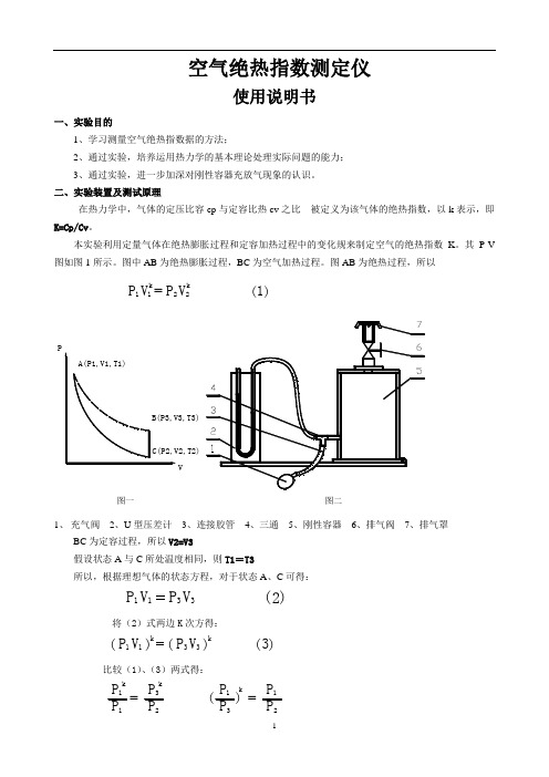
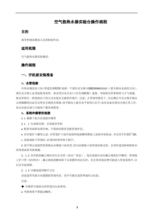
其P-V 图如图1所示。
图中AB 为绝热膨胀过程,BC 为空气加热过程。
图AB 为绝热过程,所以1P V 1k =k2V P 2( )1图二图一PV1、 充气阀2、U 型压差计3、连接胶管4、三通5、刚性容器6、排气阀7、排气罩 BC 为定容过程,所以V2=V3假设状态A 与C 所处温度相同,则T1=T3所以,根据理想气体的状态方程,对于状态A 、C 可得:2( )3P V 31V P 1将(2)式两边K 次方得:3( )=k1V P 1( )( )3P V 3k比较(1)、(3)两式得:1P k=P 12P kP31P P 23P =k P 1( )将上式两边取对数,得:K ln ( )1P P 23P P 1( )n l ( )4 因此,只要同A 、B 、C 三状态下的压力,P1、P2、 P3,且将其代入(4)式,即可求得空气的绝热指数K 。
三、实验设备本实验的实验设备如图2所示图二图一PV实验时,通过充气阀对刚性容器进行充气,至状态A ,由U 型差压计测得A 状态的表压力为h1mmH2O,如图3状态A ,我们选取容器内一部分气体作为研究对象,其体积为V1,压力、温度为P1、T1,假设通过排气阀放气,使其压力与大气压力相平衡,恰好此时V1的气体通过膨胀至整个容器(体积为V2),立刻关闭排气阀,膨胀过程结束。
因此P2=P (大气压力),由于此过程进行得十分迅速,可忽略容器的传热。
因而可以认为此过程为定量气体的绝热膨胀过程,即由状态A (P1,V1,T1)绝热膨胀至状态B (P2,V2,T2)。
ARES用户操作手册

ARES 流变仪用户操作手册目录第一章 ARES介绍 (3)第二章校准ARES (7)1、扭矩校正 (9)2、法向力校正 (10)3、应变校正 (11)第三章 ARES温度控制系统 (13)第四章 ARES夹具 (16)第五章实验过程 (18)1:动态模式 (20)2:稳态模式 (23)3:瞬态模式 (24)4:测试选项(Options) (28)第六章 ARES的维护 (33)1.过滤器维护 (33)2.空气轴承锁 (33)3.ARES电源 (33)4.实验过程 (33)5.安全信息 (34)6.寻求帮助 (34)ARES操作手册第一章 ARES介绍1)下图为ARES正面图,各个组件如图所示液氮罐液晶屏力学传感器FCO温控炉驱动马达马达和温控炉冷却氮气液氮汽化器2)下图为ARES侧面图压缩空气管控炉压缩空与压缩氮气测试头升降按钮ARES流变仪3)开机过程1、打开空压机,待压力表达到规定数值后方可开机,压力表规定数字如下图所示传感器压力表调至 35 psi马达压力表调至60psi温控炉压力表调至40psiFCO温控炉内压缩空气与压缩氮气转换阀请注意,这些压力在TA工程师调整好后请不要轻易调节。
2、待压力表达到规定数值后,将空气轴承解锁,如下图、待稳定后,打开位于ARES 后部的主电源开关。
3液晶屏幕上得温度一项会依次出现CAL1,CAL2,当最终显示温度后运行Orchestrator 软件随机携带的CD-ROM 装入PC ,会自动运行安装程序; 电脑;;(请妥善保管随机提供的密码文件) 与ARES 主机联机。
Orchestrator 的安装:将选择English 版本进行安装;待软件安装完成后,重新启动启动安装好的Orchestrator 操作软件;第一次运行软件,将要求提供注册密码一旦通过密码后,出现如下的对话框Instrument ID 请输入仪器类型 ARES;Data Directory 用默认值;Instrument Type 选择Shear Strain-Controlled: ARES, RDA, RDS, RFS, RPR, RMSInstruments Port 选COM1;Baud Rate 选 38400Transit Speed 选 Fast注意,必须将COM1端口的FIFO选项去掉,否则仪器将不能与电脑进行联机,具体方法如下:开始——控制面板——系统——硬件——设备管理器,会出现如下图选择属性选择端口设置——高级,去掉选项“使用FIFO缓冲区”得到如下图所示第二章校准ARES校准工具包如下图所示校准用标准油应变校正工具传感器校正工具内六角扳手校正用标准砝码如下图,将滑轮和校准工具安装在ARES 上法向力校正夹具校正用滑轮安装好后应该如图所示1、扭矩校正1.在Orchestrator操作软件中,选择 Utilities > CalibrationInstrument > Transducer Characteristics ;2.选择 “XducerCal” 按钮,点击 “Zero”按钮;3.约等待30秒后,仪器传感器清零;1.如图所示,根据下表将合适的砝码通过塑料线挂在夹具上;2.在输入点击 “Torque Cal”后,输入相应的扭矩值;3.点击OK。
空气质量检测仪使用说明书

分光打印室内空气检测仪(电脑版可调式六合一中文显示分光光度打印室内空气检测仪器)数据可调型使用说明书尊敬的客户:您好!为保证您在使用过程中具有更好的安全性和有效性,请您务必注意以下事项:1.为了确保您能够正常操作,在使用仪器前,请仔细阅读仪器使用说明书。
2.我公司仪器以便于携带和现场快速检测为其主要特点,对被测样品的品质和安全能够实现快速现场检测;其检测结果可以作为法律裁决的前期基础参考数据。
3.仪器所用试剂为化学药品,绝对禁止儿童及无关人员接触试剂,否则发生意外责任恕请自负。
4.使用仪器须知:检测结束后,必须关闭所有仪器设备的电源,以免发生以外。
注意吸收瓶和仪器的连接,防止倒吸,损毁仪器。
启动仪器之前注意胶管位置,避免触地,防止异物吸入。
不要在没有流量或流量很小的情况下长时间让气泵处于工作状态,以免影响机器寿命。
仪器工作时要保持水平。
防止仪器剧烈振动。
切开检测管时注意伤手,玻璃渣要妥善处理。
使用三脚架时注意平衡。
仪器特点▲多功能:可检测室内空气中的甲醛、苯、氨、甲苯、二甲苯、TVOC有害气体。
▲流量稳定:为了适应室内环境监测的需要,该仪器采用了大流量泵,可调阻力流量计,具有流量稳定,精度较高的特点,能很好适应苯、氨、甲苯、二甲苯、TVOC 等检测管有较大采样阻力的情况;▲自动控制:可在0~99小时内任意设定时间,操作方便、直观。
在控制面板设定采样时间,采样结束时自动停止工作。
时间精度高,采样误差不超过0.1秒;▲温、湿度指示:面板上可以显示检测现场的温度及湿度,可以直观地反映采样现场的环境状况(可选)。
▲现场测定甲醛含量。
▲甲醛超限声、光报警提示。
▲现场热敏打印定制格式的检测报告。
▲轻便:本仪器体积小,重量轻,携带方便。
▲电源:接220V交流电,强电、弱电分别独立控制。
▲包装:仪器的外包装为小型铝合金手提箱。
▲采样支架:另外配有采样三脚架,方便调整采样高度。
(可选)技术指标1.测试项目:甲醛、苯、氨、甲苯、二甲苯、TVOC2. 测量范围:甲醛(0.01~1.2mg/m3)苯(0.05~4mg/m3)氨(0.05~ 3mg/m3)甲苯(0.05~4mg/m3)二甲苯(0.05~4mg/m3)TVOC(0.05~4mg/m3)3. 流量范围:流量6X2.5升/分4. 光源:LED硅光二极管,波长630nm5. 准确度:甲醛测量精度≤2%.6. 现场热敏打印定制格式的检测报告7. 流量稳定性:>95%8. 定时控制:0—99小时9. 功率:120W10. 电源:220V交流电11.主机标准尺寸:410×280×145(mm)12.操作面板尺寸:400×270(mm)13. 重量:6kg14. 蓝色背景灯屏,便于阴暗天气使用15. 可同时检测6种气体仪器操作仪器分为定时操作区、甲醛流量调节区、甲醛测定区三个部分,通过定时操作可以设定各个检测项目所需要的的检测时间,检测甲醛时可以通过向左向右调节流量计下方的圆形旋扭来调整检测甲醛时每分钟的空气通过量,甲醛测定区通过操作可以进行甲醛测定、打印等工作。
空气质量检测仪器使用说明书

空气质量检测仪器使用说明书使用说明书一、产品概述空气质量检测仪器是一款高精度的仪器设备,用于测量和监测空气中的各种空气污染物浓度。
该仪器采用先进的传感技术和数据处理技术,具有稳定可靠、高精度、简便易用的特点,可以在室内和室外环境中广泛应用。
二、安全提示1. 在操作仪器之前,请仔细阅读本使用说明书,并确保您完全理解并掌握了正确的操作方法。
2. 在使用仪器时,请务必佩戴防护手套和口罩,以避免对人体造成伤害。
3. 请勿将仪器暴露在高温、潮湿或尘土环境中,以免影响仪器性能。
4. 如发现仪器异常情况或故障,请立即停止使用,并与售后服务中心联系。
三、仪器组成空气质量检测仪器由以下组件组成:1. 主机:包含传感器、显示屏等核心部件。
2. 电源适配器:用于给仪器供电。
3. 数据线:用于仪器与计算机或存储设备之间的数据传输。
4. 附件:包含校准气体、取样管等配件。
四、操作方法1. 准备工作a. 确保仪器已连接到电源适配器,并打开电源开关。
b. 检查传感器是否干净并无刮擦,如有污物,请使用干净的布轻轻擦拭。
c. 检查附件是否齐全,校准气体是否在有效期内。
2. 开机与仪器校准a. 按下电源开关,待仪器自检完成后,进入校准界面。
b. 按照校准气体的使用说明进行校准操作,确保仪器读数准确。
c. 校准完成后,仪器将进入工作状态,可以开始测量。
3. 测量操作a. 选择要测量的污染物类型,并设置相应的测量单位。
b. 将仪器放置在待测区域,确保传感器处于通风状态。
c. 开始测量后,仪器将实时显示空气中污染物的浓度,并记录数据。
4. 数据处理与存储a. 仪器可通过数据线与计算机或存储设备相连,将测量数据传输到计算机中进行处理。
b. 仪器内部具有存储功能,可将测量数据保存在内部存储器中,方便后续查阅。
五、注意事项1. 请按照使用说明书中的操作方法正确操作仪器,避免对仪器造成损坏或故障。
2. 在测量过程中,请注意环境的变化情况,确保测量结果的准确性。
Testo 最新一代气流速度和空气质量仪测试仪说明书
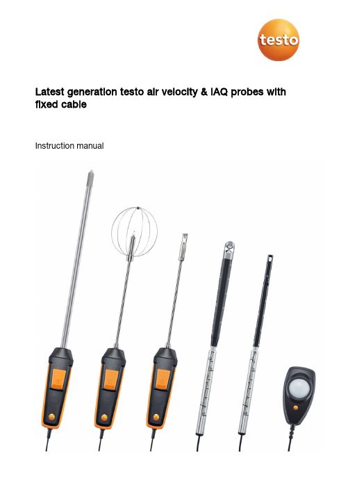
Latest generation testo air velocity & IAQ probes with fixed cableInstruction manualContents Contents1About this document (3)2Safety and disposal (3)3System description (4)4Description of the instrument (5)4.1Hot wire probe, including temperature sensor (0635 1032) (5)4.2Vane probe (Ø 16 mm) (0635 9532) (6)4.3High-precision temperature/humidity probe up to +180°C (0636 9775) 64.4Lux probe (0635 0551) (7)4.5Turbulence probe (0628 0152) (7)4.6Laboratory flue probe (0635 1052) (8)5Commissioning (9)6Maintenance (9)6.1Maintaining the probes (9)6.1.1Cleaning the instrument (9)6.1.2Calibration (9)7Technical data (10)8Accessories and spare parts (13)1 About this document1About this document•The instruction manual is an integral part of the instrument.•Please read this instruction manual through carefully and familiarize yourself with the product before putting it to use.•Pay particular attention to the safety instructions and warning advice in order to prevent injury and damage to the product.•Keep this documentation to hand so that you can refer to it when necessary.•Always use the complete original instruction manual.•Hand this instruction manual on to any subsequent users of the product.2Safety and disposalSecurity•Only use the product properly, for its intended purpose, and within the parameters specified in the technical data. Do not apply any force. •Dangers may also arise from the systems being measured or the measuring environment: always comply with the locally valid safety regulations when carrying out measurements.•Do not carry out any contact measurements on uninsulated, live parts. •Do not store the product together with solvents. Do not use any desiccants. •Only carry out maintenance and repair work on this instrument which is described in the documentation. Follow the prescribed steps exactly when doing the work. Use only original spare parts from Testo.•Temperature information given on probes/sensors relates only to the measuring range of the sensor technology. Do not expose handles and feed lines to temperatures in excess of 50°C (122°F), unless they are expressly authorized for use at higher temperatures.•Do not operate the instrument if there are signs of damage on the housing or supply lines.33 System description4Disposal• At the end of its useful life, deliver the product to the separate collectionpoint for electric and electronic devices (observe local regulations) or return the product to Testo for disposal.•WEEE Reg. no. DE 753343523 System descriptionYou have acquired a probe, if applicable with additional probe-specific accessories.The probe can be directly connected to the testo 440 measuring instrument.You will find detailed information about how each of the probes works along with the testo 440 measuring instrument in the corresponding chapter of the instruction manual for the measuring instrument.4 Description of the instrument54 Description of the instrument4.1 Hot wire probe, including temperaturesensor (0635 1032)ApplicationIn conjunction with the testo 440, the hot wire probe is suitable for flow and humidity measurements in ventilation ducts. Structure1 Sensor with protective sleeve2 Probe adapter3 Telescope with scaling 4Cable 5 Connection plugCAUTIONDamage to sensor possible! - Do not touch sensor!- Close the protective sleeve after the measurement.Low flow velocities may result in greater measurement uncertainties during temperature and humidity measurement. The probe should be switched on outside a duct under the following conditions: Ambient temperature: 20°C Flow: approx. 0 m/s.Collapse the telescope after use and do not constrict with the cable.4 Description of the instrument64.2 Vane probe (Ø 16 mm) (0635 9532)ApplicationIn conjunction with the testo 440, the vane probe (Ø 16 mm) is suitable for flow measurements in ventilation ducts. Structure1 Probe head2 Telescope3 Telescope handle4 CableCAUTIONDamage to sensor possible! - Do not touch sensor!- Put the protective sleeve on after the measurement.Collapse the telescope after use and do not constrict with the cable. 4.3 High-precision temperature/humidityprobe up to +180°C (0636 9775)ApplicationIn conjunction with the testo 440, the high-precision temperature/humidity probe is used to measure humidity and temperature. Structure1 Probe head 2Sintered cap 3 Probe shaft 4 Handle 5 CableCAUTIONDamage to sensor possible! - Do not touch sensor!4 Description of the instrument74.4 Lux probe (0635 0551)ApplicationIn conjunction with the testo 440, the lux probe is used to determine the illuminance of workplaces. In general, the illuminance measurement of warm light or white LEDs is possible because these types of LED cover the whole spectral range of the human eye. The measurement of one-colour LEDs (e.g. blue LEDs) is not recommended. Structure1 Measuring sensor2 CableCAUTIONDamage to sensor possible! - Do not touch sensor!4.5 Turbulence probe (0628 0152)ApplicationIn conjunction with the testo 440, the turbulence probe is used for temperature and air pressure measurement. Structure1 Sensor2 Guard3 Probe shaft4 Handle5 Cable4 Description of the instrument8Damage to sensor possible! - Do not touch sensor!The probe contains sensitive components. Please handle the probe with care.4.6 Laboratory flue probe (0635 1052)ApplicationIn conjunction with the testo 440, the laboratory flue probe is used to determine flow velocities in laboratory fume cupboards. Structure1 Sensor2 Protective sleeve3 Button 4Handle 5 CableATTENTIONDamage to sensor possible! - Do not touch sensor!- Push the protective sleeve over the sensor after the measurement.The probe contains sensitive components. Please handle the probe with care.Low flow velocities may result in greater measurement uncertainty during temperature measurement!5 Commissioning95 CommissioningDisplaying readings✓Sensor is connected to the measuring instrument.Readings are displayed.6 Maintenance6.1 Maintaining the probes6.1.1 Cleaning the instrumentDo not use any aggressive cleaning agents or solvents; instead use mild household cleaning agents or soapy water.Always keep the connections clean and free from grease and other deposits.Clean the instrument and the connections with a damp cloth and dry them off.6.1.2 CalibrationThe probes are supplied with a factory calibration protocol as standard. Recalibration of the probes once every 12 months is recommended in many applications. This can be carried out by Testo Industrial Services (TIS) or othercertified service providers with the aid of easy-to-use service software. Please contact Testo for further information.7 Technical data107 Technical data• Adjustment conditions for flow probes:Adjustment in free jet Ø 350 mm, reference pressure 1013 hPa, based on testo reference Laser Doppler Anemometer (LDA). • Note for flow probes:Low flow velocities may result in greater measurement uncertainties during humidity and temperature measurement! • Note for humidity probes:Please do not use the humidity probes in condensing atmospheres. For continuous use in high-humidity ranges > 80% RH at ≤ 30°C for > 12 h > 60% RH at > 30°C for > 12 hplease get in touch with Testo Service or contact us via the Testo website.Hot wire probe, including temperature sensor (0635 1032) FeatureValueMeasuring range0 to +30 m/s -20 to +70°C 700 to 1100 hPaAccuracy(at 22°C, ± 1 digit)± (0.03 m/s + 4% of m.v.) (0 to 20 m/s) ± (0.5 m/s + 5% of m.v.) (20.01 to 30 m/s) ± 0.5°C (0 to +70°C) ± 3 hPa Resolution0.01 m/s 0.1°C 0.1 hPaStorage temperature -20°C to +70°C Operating temperature -20°C to +70°C Protection class IP20DimensionsCable length: 1.7 mExtension length with telescope: 850 mm Ø probe head on the sensor: 9 mm Ø end of probe shaft: 12 mm Weight90 gDirectives, standards and testsEU Directive: 2014/30/EU7 Technical data11Vane probe (Ø 16 mm) (0635 9532) FeatureValue Measuring range0.6 to 50 m/s Accuracy(at 22°C, ± 1 digit)± (0.2 m/s +1% of m.v.) (0.6 to 40 m/s) ± (0.2 m/s +2% of m.v.) (40.1 to 50 m/s) Resolution0.1 m/s Storage temperature-10°C to +70°C Operating temperature-10°C to +70°C Protection classIP20 Dimensions Cable length: 1.7 mExtension length with telescope: 850 mmØ probe head: 16 mmØ end of probe shaft: 12 mmWeight 148 gDirectives, standards andtestsEU Directive: 2014/30/EUHigh-precision temperature/humidity probe up to +180°C (0636 9775) FeatureValue Measuring range-20 to +180°C 0 to 100% RH Accuracy(at 22°C, ± 1 digit)±0.5°C (-20 to 0°C) ±0.4°C (0.1 to +50°C) ±0.5°C (+50.1 to +180°C) Accuracy(at 25°C, ±1 digit) ±3% RH (0 to 2% RH) ±2% RH (2.1 to 98% RH)±3% RH (98.1 to 100% RH)Additional uncertainty- Long-term stability: ±1% RH / yearResolution 0.1°C0.1% RHTemperature coefficient type (k=1) ±0.03% RH/K (-20 to +50°C)type (k=1) ±0.06% RH/K (+50 to +180°C)Storage temperature -20 to 60°COperating temperature Handle: -5 to +50°CProbe head: -20 to +180°CProtection classIP207 Technical data12 FeatureValue Dimensions Cable length: 1.4 mOverall probe length: 420 mmProbe shaft length: 270 mmØ probe shaft: 12 mmWeight 255 gDirectives, standards andtestsEU Directive: 2014/30/EULux probe (0635 0551) FeatureValue Measuring range0 to 100,000 lux Accuracy(at 22°C, ±1 digit)DIN EN 13032-1 Appendix B; Class C according to DIN 5032-7 Resolution0.1 lux < 10,000 lux 1 lux ≥ 10,000 lux Storage temperature-20 to +50°C Operating temperature0 to +50°C Ambient humidityPreferred use: 20 to 80% RH DimensionsCable length: 1.4 m Housing: 110 x 55 x 22 mm Weight 110 g Directives, standards andtestsEU Directive: 2014/30/EUTurbulence probe (0628 0152)FeatureValue Measuring range 0 to +5 m/s0 to +50°C700 to 1100 hPaAccuracy (at 22°C, ± 1 digit) ± (0.03 m/s + 4% of m.v.) (0 to +5 m/s)± 0.5°C± 3 hPaResolution 0.01 m/s0.1°C0.1 hPaStorage temperature -20 to +60°COperating temperature0°C to +50°C8 Accessories and spare parts13 FeatureValue Dimensions Cable length: 1.4 mOverall probe length: 400 mmProbe shaft length: 195 mmWeight 250 gDirectives, standards andtestsEU Directive: 2014/30/EULaboratory flue probe (0635 1052) FeatureValue Measuring range 0 to +5 m/s0 to +50°C700 to 1100 hPaAccuracy (at 22°C, ± 1 digit) ± (0.02 m/s + 5% of m.v.) (0 to +5 m/s)± 0.5°C± 3 hPaResolution 0.01 m/s0.1°C 0.1 hPaStorage temperature -20 to +60°COperating temperature 0°C to +50°CDimensions Cable length: 1.4 mOverall probe length: 350 mmProbe shaft length: 195 mmWeight 230 gDirectives, standards andtestsEU Directive: 2014/30/EU8 Accessories and spare partsDescription Order no. Measuring stand with standard-compliant positioning of probes (including bag)0554 15900971 0455 en 03。
气体热值仪操作说明

气体热值仪操作说明气体热值测量仪操作说明一、适用范围:适用于本公司实验用丙烷、丁烷、天燃气等气体的热值检测。
二、热值仪说明:1. 热值仪分高低两个测量范围,低范围为:500-2000BTU/ft3 ,适合天燃气、乙烯等气体的热值测量,高笵围为:1000 - 4000BTU/ ft3 ,适合于丙烷、丁烷等气体的热值测量.2. 在500-2000BTU/ft 3 范围测量时,接“U ”形天然气进气管,进气部分水平杆表面与显示屏顶部平齐,在1000 - 4000BTU/ ft3 范围测量时,接“Y ”形LPG 进气管,进气部份水平杆表面到显示屏顶部距离为610mm (见附图1),“ U ”型管与“ Y ”型管可快速拆装.三、操作程序:1. 确保仪器安装正确,各管路闭封良好。
2. 接上电源,显示器显示数据.在低范围测量时,示窗显示数据400-500内;在高范围测量时,示窗显示数据900-1000内(见附图2),此为正常开机显示状态.指示与数据范围不符时需重新设定;3. 测量范围设定:热值仪的控制面板下方有“测量范围设置图”(见附图2),根据图示设定测量上限和下限.例如:在低范围测量时,按图示设定测量下限为500后,再设定测量上限为2000,设好后沿示意图返回正常开机显示状态;4. 连接待测气体(见附图3),调节供气压力在50-900mm 水柱内;5. 打开待测气体的阀门,接着打开热值仪的进气阀,提升控制阀上的顶针(见附图4),让气体进入热值仪的燃烧系统,然后旋转拔下热值仪的燃烧头,用打火机点燃从燃烧头流出的气体(附图5),将燃烧头插入到燃烧炉内(附图6);6. 燃烧过程中,显示窗内的读数会慢慢上升,燃烧约2个小时后,记录下显示窗的读数,即为待测气体的热值,单位BTU/ ft3 ;7. 测试完毕,先关气源,待燃烧头熄火后,关闭电源.四、热值仪校准:1. 校500-2000BTU/ft 3 范围时使用热值为 1461.3BTU/ ft3 的标准气,校1000 - 3 的高纯丙烷(纯度<99%)4000BTU/ ft3 笵围时用热值为2575 BTU/ ft。
空气质量检测仪操作说明书

空气质量检测仪操作说明书一、引言空气质量检测仪是一种用于测量和监控环境中各种有害物质浓度的仪器。
本操作说明书旨在为用户提供正确操作空气质量检测仪的指导,确保准确的检测结果和安全的使用。
二、检测仪外观空气质量检测仪外观如图所示:[图片]三、操作步骤1. 准备工作在使用空气质量检测仪之前,用户应先确保仪器已经充电或电池已装好,并检查仪器是否处于正常工作状态。
2. 打开仪器按下电源按钮,使仪器开启。
仪器开启后,将显示屏亮起并显示当前环境空气质量指标。
3. 设置参数通过系统菜单设置仪器的检测参数,例如选择要检测的有害物质种类、设定报警阈值等。
具体设置步骤请参阅仪器配套说明书。
4. 进行检测将空气质量检测仪靠近待检测的环境,并保持仪器与环境接触稳定。
待仪器稳定后,观察显示屏上的数值并记录。
5. 分析结果根据显示屏上的数值,判断当前环境的空气质量状况。
如果达到或超过设定的报警阈值,仪器将会发出警告声音以提醒用户。
6. 结束使用使用完毕后,按下电源按钮,使仪器关闭。
然后将仪器存放在干燥、通风的地方,并妥善保管以防止损坏。
四、注意事项1. 仪器使用过程中,请避免暴露在高温、潮湿或有腐蚀性气体的环境中,以免影响检测结果和仪器寿命。
2. 操作过程中请注意个人安全,不要将仪器的探头朝向自己或他人,以免造成伤害。
3. 检测完成后,请及时清洁仪器的探头以防污染和交叉感染。
4. 请定期校准仪器,确保检测结果的准确性。
具体的校准方法请参阅仪器配套说明书。
五、故障排除1. 若仪器无任何显示,请检查电池是否充电或更换电池。
2. 若检测结果异常,请确认是否进行了正确的操作,并重新进行检测。
3. 若仪器无法正常开启或关闭,请将仪器重启并确认电源是否正常。
六、维护保养1. 定期对仪器进行清洁,尤其是探头部分。
2. 仪器长期不使用时,请将其存放在干燥、通风的地方。
七、总结空气质量检测仪是一种便捷、可靠的环境监测工具。
通过正确的操作和维护,可以确保准确的检测结果并延长仪器的使用寿命。
气体分析仪器操作说明书
气体分析仪器操作说明书一、概述本操作说明书旨在向用户提供气体分析仪器的正确操作方法和使用注意事项,帮助用户科学合理地运用气体分析仪器从而获得准确可靠的结果。
二、仪器介绍1. 仪器外观及各部件功能气体分析仪器外观应整洁美观,各部件包括显示屏、按键、连接接口等,具体功能请参考仪器的用户手册。
用户在操作仪器前应仔细阅读用户手册以了解每个部件的具体作用。
2. 仪器安装与环境要求在安装气体分析仪器之前,要确保安装环境符合仪器要求。
具体要求包括电源、温度、湿度等,用户应根据仪器的要求准备好相应的环境,并按照仪器的安装说明进行安装。
三、操作步骤以下为气体分析仪器的操作步骤,供用户参考:1. 打开电源使用供应商提供的电源线将仪器连接到稳定的电源插座上,并将电源开关打开。
待仪器启动后,显示屏上会出现相关信息。
2. 设置参数根据需要进行相关参数的设置。
不同的仪器具有不同的参数设置方式,请参考用户手册进行正确设置。
3. 样品准备与输入根据实际需求,准备好待测样品并连接到仪器的样品输入接口。
注意,样品应该是干净、无污染且符合仪器的样品规格要求。
4. 开始分析确认仪器已连接到样品后,按照指示操作,开始进行气体分析。
在此过程中,用户应严格按照仪器要求进行操作,注意观察显示屏上的信息,避免操作错误导致数据不准确。
5. 结果处理与保存分析结束后,仪器通常会提供分析结果。
用户可以根据需要对结果进行处理,并将结果保存至 U 盘、计算机或打印机等储存设备上。
四、使用注意事项为了保证气体分析仪器的正常运行和操作人员的安全,以下是一些使用注意事项:1. 仪器使用前,请仔细阅读用户手册并了解仪器的性能和操作要求。
2. 请确保操作人员具备一定的仪器操作技能,以免操作不当影响分析结果。
3. 在连接样品进样管路和气源时,确保连接口密封可靠。
4. 样品应尽量避免过高温度或压力,以免引起仪器故障或样品质量变化。
5. 仪器使用完毕后,请将电源关闭,避免长时间不使用仪器时造成不必要的能源浪费。
空气质量监测仪器操作技术手册
空气质量监测仪器操作技术手册第一章:引言空气质量是人们生活中十分重要的指标之一。
为了保障公众的健康和环境的可持续发展,我们需要准确地监测和评估空气质量。
而空气质量监测仪器则是我们实现这一目标的重要工具。
本手册旨在介绍空气质量监测仪器的操作技术,帮助操作人员正确、准确地使用仪器。
第二章:仪器概述2.1 仪器类型本节介绍主要的空气质量监测仪器类型,包括大气气体分析仪、颗粒物浓度监测仪以及多功能空气质量监测仪。
2.2 仪器结构本节详细描述了各种类型仪器的基本结构和主要组成部分,包括传感器、控制系统、数据采集与处理系统等。
第三章:仪器使用准备3.1 仪器环境条件本节介绍了使用仪器时需要考虑的环境条件,包括温度、湿度、气压等要求,以确保仪器的正常运行和准确性。
3.2 仪器校准与维护本节详细说明了仪器的校准与维护工作,包括校准方法、校准气体的选取与使用,以及仪器的日常维护措施。
3.3 安全事项本节列举了仪器使用过程中需要注意的安全事项,包括仪器操作人员的个人防护、仪器周围的环境安全等,以确保使用过程的安全性。
第四章:仪器操作步骤4.1 仪器开机与关机本节详细描述了仪器的开机与关机步骤,以确保仪器能够正常启动和关闭。
4.2 仪器参数设置本节介绍了仪器参数设置的方法与注意事项,包括仪器测量范围的选择、采样时间间隔的设置等。
4.3 仪器数据采集与记录本节指导操作人员如何进行仪器数据的采集与记录,包括数据采集的频率、数据记录的格式等。
第五章:故障排除5.1 常见故障及处理方法本节列举了仪器可能出现的常见故障及相应的处理方法,以帮助操作人员在故障发生时能够快速解决问题。
第六章:附录6.1 术语解释本节对仪器操作中常见的术语进行解释,以帮助操作人员更好地理解和应用。
6.2 操作人员常见问题解答本节回答了操作人员在使用过程中常遇到的问题,解答了他们的疑惑,提供了相关的参考和建议。
结论本文对空气质量监测仪器的操作技术进行了详细介绍,包括仪器的概述、使用准备、操作步骤以及故障排除等。
气体分析仪使用手册气体分析仪各个按键功能简单介绍
气体分析仪使用手册气体分析仪各个按键功能简单介绍气体分析仪使用手册 - 气体分析仪各个按键功能简单介绍1.简介气体分析仪是一种用于检测和分析气体成分的仪器设备。
本使用手册旨在帮助用户快速了解气体分析仪的各个按键功能,以便正确操作仪器并获取准确的检测结果。
2.按键功能介绍2.1 电源开关功能:控制气体分析仪的开关机状态。
操作:将开关切换至"ON"档,仪器开机并开始工作。
将开关切换至"OFF"档,仪器关机并停止工作。
2.2 清零键功能:用于将仪器的读数清零。
操作:在待测气体采样前,按下清零键将当前读数清零。
2.3 记录保存键功能:用于保存当前的检测数据记录。
操作:在检测到需要保存记录时,按下记录保存键,当前数据将会被保存并记录。
2.4 菜单键功能:进入设置菜单,用于调整仪器的参数和功能设置。
操作:按下菜单键进入菜单界面,根据菜单指示进行相应的参数和功能设置。
2.5 上下箭头键功能:用于调整仪器参数或浏览菜单选项。
操作:按下上箭头或下箭头键可上下滚动浏览菜单选项,或者调整参数值。
2.6 确认键功能:用于确认菜单选项或参数设置。
操作:在菜单选项或参数设置完成后,按下确认键以确认并保存设置。
2.7 取消键功能:用于取消菜单选项或参数设置。
操作:在菜单选项或参数设置过程中,按下取消键可取消当前操作并返回上一级菜单。
2.8 检测键功能:开始气体检测和分析。
操作:在确认参数设置无误后,按下检测键开始进行气体检测。
仪器将采集并分析待测气体,并显示检测结果。
3.注意事项在操作气体分析仪时,请仔细阅读使用手册并遵循操作规范,以确保仪器的正常工作和准确检测结果。
请勿随意更改仪器的参数设置,除非您明确了解对测量结果的影响。
请勿在高温、高湿度、强磁场或腐蚀性气体环境中使用气体分析仪,以免损坏仪器。
定期检查并维护气体分析仪,保持仪器的良好工作状态。
以上是气体分析仪各个按键功能的简单介绍,希望对您使用气体分析仪有所帮助。
空气质量检测仪器操作指南说明书

空气质量检测仪器操作指南说明书操作指南说明书一、引言空气质量检测仪器是一种用于测量和监测空气中各种污染物含量的设备。
本操作指南旨在为用户提供详细的操作步骤,以确保正确、安全地使用空气质量检测仪器,并准确解读检测结果。
在使用本仪器前,请务必仔细阅读本指南,并按照指南中的步骤进行操作。
二、检测仪器概览在正式操作检测仪器之前,我们先来了解一下其主要组成部分:1. 主机:包含显示屏、控制面板和数据处理模块。
通过控制面板,用户可以进行各种设置和操作。
2. 传感器:用于测量空气中污染物的浓度。
传感器的数量和类型根据不同型号的检测仪器而异。
3. 电源:为检测仪器提供电力,可以使用电池或外部电源。
4. 采样系统:用于收集空气样本,并将其送入传感器进行分析。
三、操作步骤1. 准备工作:a) 确认所使用的检测仪器是否处于正常工作状态。
检查各项指示灯是否亮起,并检查显示屏上的信息是否正常。
b) 根据需要,连接外部电源或安装电池,并确保电源供应充足。
c) 将采样管或其它采样设备正确安装在检测仪器上,确保接口连接紧固。
2. 仪器开机:按下电源按钮,待仪器启动完成,显示屏上将显示设备信息和当前环境参数。
3. 参数设置:a) 根据所需检测项目,使用控制面板上的功能键设置相关参数。
例如,可选择检测的污染物种类、时间间隔以及预警阈值等。
b) 确定检测的位置和时间,选择适当的检测模式。
可以选择实时监测或定时取样。
4. 采样操作:根据需要,选择采样方式,手动采样或自动采样。
手动采样时,通过控制面板上的按钮来控制采样时间和结束。
自动采样时,根据设定的参数,仪器将按预定时间间隔进行采样。
在采样过程中,要保持仪器稳定,避免震动和剧烈晃动。
同时,注意防止无关物质污染样品。
5. 结果分析:a) 仪器将根据采样的空气样品进行分析,并将结果显示在屏幕上。
根据仪器性能,有的仪器还可以输出打印结果或连接至电脑进行数据分析。
b) 仪器的显示屏上将显示不同污染物的浓度值。
多功能空气检测器用户手册说明书
Multifunctional Air DetectorUser ManualBe sure to carefully read this user manual regarding use and keep it forfuture reference.I. IntroductionThis product is a multifunctional air detector that detects Formaldehyde (HCHO), Total Volatile Organic Compounds (TVOC), and Particulate Matter <2.5 micron-sized particles (PM2.5) with clock and air quality record chart. As a professional and scientific air detection device, it combines advanced sensor technology with a built-in fan to allow real-time monitoring of formaldehyde (HCHO), total volatile organic compounds (TVOC), and PM2.5 on its digital LCD display.Features:2.8" color liquid crystal display (LCD)User adjustable alarm threshold to alert of hazardous conditionsGreen/yellow/red indicator corresponding to three air quality levels: Fresh, Unqualified (i.e. borderline fresh but not qualified as fresh),and Polluted.Large 2200 mAh capacity Lithium battery5V 800mA Micro USB chargingLow battery warningWhy measure TVOC and Formaldehyde? TVOCs are carbon-containing compounds produced by synthetic processes, materials, and organisms. Formaldehyde has suspected links to nasal cancer and lung cancer and emitted from many household materials. Most known carcinogens are synthetic organic compounds as they can interact with DNA to cause mutations/cancer. A combined measure can give a picture of relative indoor pollution levels and synthetic gas accumulation.DIRECTIONS TO MEASURE AIR QUALITY1.Charge device on receipt until battery level is at least half fullbefore initial use. Power on device to determine battery level.Place device in a well ventilated area for 20-60 minutes.2.Power on device. Detector will begin initiation process for 3 minutesallowing sensors to preheat and fan to draw in fresh ambient air.This is necessary for accurate results. LED screen will display thecountdown number from 180 to 0 seconds.3.To measure air quality, place device in any location for at least 5minutes for most accurate and stable readings of formaldehyde(HCHO), TVOC, and PM2.5.4.After detection, turn device off and store in a cool, dry area.5.If item is newly purchased or has not been used for long periods, itmay accumulate gases from packaging that can affect detection results. In this case, place the device before use in fresh well-ventilated air for at least 20 minutes, leaving it unused during this period. Should results appear inaccurate despite ventilation, consider calibration by referring to CALIBRATION procedure.CALIBRATIONLike all scientific instruments, you can calibrate it initially or after long storage for greatest reproducibility and accuracy of results.Calibration procedure is for formaldehyde and TVOC sensor. PM2.5 particular matter sensor does not require calibration. This procedure is best done OUTDOORS where formaldehyde and TVOC levels are generally negligible.Video of procedure for calibration:https:///watch?v=Y9ZdjQy2qAg1. Turn on unit by sliding left sided button upwards.2. Allow device to fully start up by allowing TVOC counter to count to 0.3. Place device in a CLEAN OUTDOOR AIR environment for 5+ minutes where there is no formaldehyde or TVOC. Putting the device outside for at least 5 minutes allows full circulation of outside air into the device. Putting the device outside longer may be even better. Place the device outside before proceeding further.*Generally outdoors is a clean environment with negligible formaldehyde and TVOC. Do this procedure away from traffic or combustion sources.4. Push center button once to enter Menu and 2 additional times to highlight "Sensor Calibration" in red.5. Push the left < button to select "OK"6. Push the left < button to select "Calibrate"7. Push the left < button twice to select "OK" and confirm while outside.8. Push the right > button twice to select "Back" and exit to the main screen. You will see that device has set the HCHO and TVOC readings as 0.000 mg/m3.You can confirm device has been calibrated after exiting to the main screen and seeing device reads 0.000 mg/m3for HCHO and TVOC. Calibration means device has set 0.000 mg/m3as corresponding to clean outdoor air which generally has negligible or near zero HCHO and TVOC. One can think of calibration as zeroing a weight scale.HCHO and TVOC are most commonly emitted by synthetic materials and accumulate indoors and degrade outdoors. DO NOT CALIBRATE unless you have access to clean air free from formaldehyde and TVOC (organic compounds). Avoid calibrating indoors where HCHO and TVOC are usually higher. If you try calibrating your device indoors (NOT recommended), you will notice that the device will read 0.000 mg/m3 indoors and will show low and inaccurate numbers.Why are there significant differences in HCHO and TVOC readings at different times?There can be large variations in formaldehyde (HCHO) and TVOC readings within a house on different days and in different rooms.The total volatile organic compound (TVOC) readings can vary by magnitude of 10 or more on different days. Anything from cooking to perfume to body odor near the device can cause large variations in the TVOC readings. Think of the device as a very sensitive electronic nose.Remember to calibrate ESPECIALLY if you are getting inaccurate readings or after storage as most product boxes are made from a large amount of synthetic materials that emit HCHO and TVOC's and can cause inaccurate readings.Why is the TVOC reading 9.999 mg/m3?Make sure there are no fragrances, body odors, perfumes, smoke, aromas, detergent or cooking smells near the device as these all are benign sources of total volatile organic compounds (TVOCs). They will lead to higher TVOC concentrations and an elevated or 9.999 mg/m3 reading as the device is sensitive and the human nose is often exposed to TVOC concentrations far greater than 10 mg/m3. Do not be alarmed if TVOCs are elevated as TVOCs include any organic or biologic odors dispersed in the air, the majority benign. If you take the device outside, the TVOC reading should be near 0.000; if not, please be sure to calibrate the device.AIR LEVEL QUALITY AND GRADE1.When formaldehyde (HCHO) concentration is less than 0.080mg/m3 and PM2.5 is less than 55, LCD screen displays Level as Fresh in green and air quality is fresh.2.When formaldehyde (HCHO) concentration is between 0.080 to0.300 mg/m3or PM2.5 is between 55 to 250 mcg/m3,LCDscreen displays Level as Unqualified in yellow, meaning air is in a borderline condition not qualified as Fresh but not meeting criteria for hazardous pollution.3.When formaldehyde (HCHO) density is greater than 0.300 mg/m3or PM2.5 is greater than 250 mcg/m3, LCD screen displays the Level as Polluted or Hazardous in red, meaning air quality is considered polluted and not safe for prolonged exposure. Corrective action including ventilation of the area should be taken.Formaldehyde Level InterpretationThe World Health Organization guideline for indoor air formaldehyde concentration is 0.10 mg/m3 (0.08 ppm). The California Air ResourcesBoard recommends an “action level” of 0.1228 mg/m3 (0.1 ppm) and a “target level” of 0.0614 mg/m3 (0.05 ppm) or lower for homes.PM2.5 Level InterpretationAccording to the EPA, here are levels of PM2.5 or dust particulate matter measuring 2.5 micrometers or less considered healthy/unhealthy:•GOOD: 0.0-12.0 µg/m3•MODERATE: 12.1-35.4•UNHEALTHY FOR SENSITIVE GROUPS: 35.5-55.4 •UNHEALTHY: 55.5-150.4•VERY UNHEALTHY: 150.5-250.4•HAZARDOUS: 250.5-500.4Total Volatile Organic Compound Level InterpretationMeasuring total volatile organic compounds(TVOC), sometimes chemical pollutants, are helpful but also more difficult to interpretwhen determining air quality grade. This is because hazard levels with TVOC are specific to the actual organic compound(s) in the air; some synthetic organic compounds are hazardous whereas many natural organic compounds are harmless.The U.S. Green Building Council’s recommended h ealthy building level is 0.500 mg/m3. However, data from hundreds of homes measured by homeowners show the median value is 1.200 mg/m3, more than twice the recommended level. No absolute numbers can be attributed to certain hazard as they vary with each organic compound. Even one’s breath can cause a spike in TVOC levels but is not considered harmful. However, relative TVOC levels can be useful to measure if you are aware of the type of organic compounds present such paint fumes or benzene/aromatic compound fumes. A house with high mold concentration or building material off gassing is associated with high TVOC levels. Treating high humidity conditions with a dehumidifier or opening windows for venting is usually the most effective strategy to reduce TVOC and formaldehyde levels.Many harmful or carcinogenic compounds are synthetic organic compounds that are easily inhaled into the body as they are “volatile” or easily evaporated at room temperature.Can you inform me how to convert mg/m3to ppm for formaldehyde?For formaldehyde,At 760 mmHg and 20 °C, 1 ppm = 1.249 mg/m3 and 1 mg/m3= 0.801 ppm;At 25 °C, 1 ppm = 1.228 mg/m3 and 1 mg/m3 = 0.814 ppm.Conversion factor from mg/m3 to ppm for TVOC varies with each specific organic compound since molecular weights of individual organic compounds are different. Identification of specific organic compound is needed.III. TYPES OF INTERFACE (MENU)With the default Overall Interface, the time, battery level, air quality level, formaldehyde (HCHO) concentration, Total Volatile Organic Compound (TVOC), and PM2.5/10 concentrations are displayed.To access the Menu Interface, press the center button labelled. Pressing the center button again allows downward selection within the menu in RED. The Left < button and Right > button select options on the screen such as “OK” or “Back.”•System SettingYou can set [OFF time] for time period before self-shutoff, [Version] for interface style, [Factory Settings] to reset device, and [Time Setting] to set the time and date.•Alarm SettingsDefault alarm threshold when alarm sounds is 0.10 mg/m3. However, the user can set a different HCHO alarm threshold by pressing the left button to (+)or right button to (-) alarm threshold. Alarm will ring when HCHO level is exceeded.To turn off alarm entirely, press center button within Alarm Interface to highlight ON/OFF selection Blue. Press left button to turn alarm ON/Open and right button turn alarm OFF/Close. Press center button to exit to Menu Interface and “Back” to Overall Monitoring Interface.•HCHO/TVOC/PM2.5 RecordsYou can view HCHO/TVOC/PM2.5 current record chart. ‘ is for minutes and “ is for seconds elapsed.IV. HOW TO CHARGEThis product comes with built-in lithium battery charged by 5V micro USB. Suggested charging time is 4 hours. When charging, battery status displays icon. When full charged, battery status displays icon.•When battery status turns to , battery level is low;please charge device immediately to prevent shut off.•When LCD screen displays "Lowest power, please charge", device will turn off automatically after 3 seconds.Continuous air quality monitoring can be achieved by charging device with micro USB cable while monitoring and setting [OFF time] for time period of 2 days found under System Settings within Menu interface.V. TECHNICAL PARAMETERS•Display Mode: High-definition liquid crystal display (LCD) with 240 x 320 resolution•Product Dimension: 150 x 70.8 x 43.6 mm•Product Weight: 188 g•Battery Capacity: 2200mAh•Lithium Battery Input: 5.0V, 800mA•Charging Temperature: -10°C - 45°COperation Environment•Atmospheric Pressure: 86Kpa - 106Kpa•Humidity Range: 20% - 85%•Working Temperature: -10°C - 45°C•Storage Temperature: -20°C - 50°CFormaldehyde or HCHO•Test Item: atmospheric HCHO•Test Range: 0.000-1.999 mg/m3•Sampling Method: Diffusion Type•Concentration Unit: mg/m3•Sensor type: electrochemical semiconductor sensorTotal Volatile Organic Compounds or TVOC∙Test Item: TVOC in the air including potentiallycarcinogenic aromatic compounds and benzene∙Test Range: 0.000 - 9.999 mg/m3∙Sampling Method: Diffusion Type∙Concentration Unit: mg/m3∙Sensor type: electrochemical semiconductor sensorPM2.5/PM10•Tested particle diameter: PM2.5 or <2.5 micrometer particle concentration (PM10 via calculation from PM2.5) •Sampling Time: 3 seconds•Sensor type: Laser Detection Sensor•Detection range: 0-999 mcg/m3Produced for and Manual written/edited by EG AIR。
气体分析仪操作说明

气体分析仪操作说明一、前言气体分析仪是一种用于测量和分析气体成分的仪器。
本操作说明旨在帮助用户正确操作气体分析仪,以达到准确并安全地进行气体分析的目的。
在使用气体分析仪之前,请仔细阅读本操作说明,并按照操作步骤进行操作。
二、设备准备在操作气体分析仪之前,需要确保以下准备工作已完成:1. 确保气体分析仪已连接到电源,并处于正常工作状态。
2. 确保所需被测气体已经准备好,并接入到气体分析仪中。
3. 清理并检查气体分析仪的传感器和探头,确保其表面干净无污染。
三、操作步骤以下是气体分析仪的操作步骤:1. 打开仪器按下仪器上的电源按钮,等待仪器启动。
确保仪器显示屏正常亮起,并进入运行状态。
2. 设置测量参数根据需要,使用仪器上的菜单或按钮设置所需的测量参数。
这些参数可以包括被测气体种类、测量单位、采样时间等。
3. 进行预热在开始气体分析之前,需要给仪器一定的预热时间以确保准确性。
根据仪器设备的要求,预热时间一般为几分钟至十几分钟不等。
4. 开始采样将气体分析仪的探头靠近被测气体源,按下采样按钮开始采样。
在采样过程中,保持探头与气体源的接触,并尽量避免探头受到外界干扰。
5. 数据记录与分析仪器会实时显示测量结果,在采样过程中可以进行数据记录。
根据需要,可以使用仪器上的数据存储或传输功能,将测量数据导出到计算机或其他设备进行进一步分析和处理。
6. 结束操作在完成气体分析后,按下仪器上的停止按钮或关机按钮,将仪器关闭。
断开与被测气体源的连接,并进行必要的清洁和维护工作。
四、注意事项在操作气体分析仪时,需要注意以下事项:1. 遵循操作规程:按照操作说明书上的步骤进行操作,避免随意更改操作流程或参数设置。
2. 安全使用:在操作时请佩戴适当的防护设备,确保操作环境良好通风,并避免有害气体直接接触皮肤或吸入呼吸系统。
3. 校准与维护:定期对气体分析仪进行校准和维护,以确保其准确性和可靠性。
4. 故障处理:在使用过程中如遇到异常情况或故障,请查阅仪器的使用手册或寻求专业人员的帮助。
空气预热器运行和说明书

29-VI(T)-SMR空气预热器运行和说明书17.YX3300.001编写:张玉珠校对:审核:审定:批准:哈尔滨锅炉厂有限责任公司2003年8月8日目录1.容克式空气预热器的工作原理主要技术规范、重要图纸清单 (2)2.传热元件 (4)3.支承轴承 (9)4.导向轴承 (12)5.转子传动装置 (14)6.空气预热器润滑 (15)7.空气预热器密封 (16)8.空气预热器运行 (22)1前言本说明书参照美国ABB(现为ALSTOM)空气预热器公司提供的典型Ⅵ型半模式结构空气预热器运行和维修说明书编写的。
转子停转报警装置、支承轴承和导向轴承用的油循环设备、着火探测系统、转子传动装置及控制和吹灰器等本文仅作简要概述,详见各有关的说明书。
为转子的圆柱形外壳内,转子之外装有转子外壳,转子外壳的两端同连接烟风道相联。
预热器装有径向密封和旁路密封,形成预热器的一半流通烟气,另一半流通空气。
当转子慢速转动时,烟气和空气交替流过传热元件,传热元件从热烟气吸收热量,然后这部分传热元件受空气流的冲刷,释放出贮藏的热量,这样空气温度大为提高。
本机组的回转式空气预热器为Ⅵ型,三分仓半模式,采用内置式支承轴承。
1.2 主要技术规范传热元件热端 0.5mm FNC型碳钢热端中间层 0.5mm FNC型 CORTEN钢冷端 0.8mm DU3型SPCC-SD钢(搪瓷)转子密封——热端和冷端径向密封片δ= 2.5mm CORTEN钢转子中心筒密封片δ= 6 mm CORTEN钢轴向密封片δ= 2.5mm CORTEN钢旁路密封片δ= 1.5mm CORTEN钢转子传动装置减速机:正常输出轴转速为0.85转/分。
主电机:型号:M2QA-W160M6B B3型 7.5KW,380V,17A ,970 RPM 双轴伸。
备用电机:型号:M2QA-W160M6B B3型 7.5KW,380V,17A ,970 RPM 双轴伸。
转子正常转动速度: 0.85RPM;采用变频调速慢速挡转子转动速度:0.21转/分。
科学实验室空气压力仪说明书
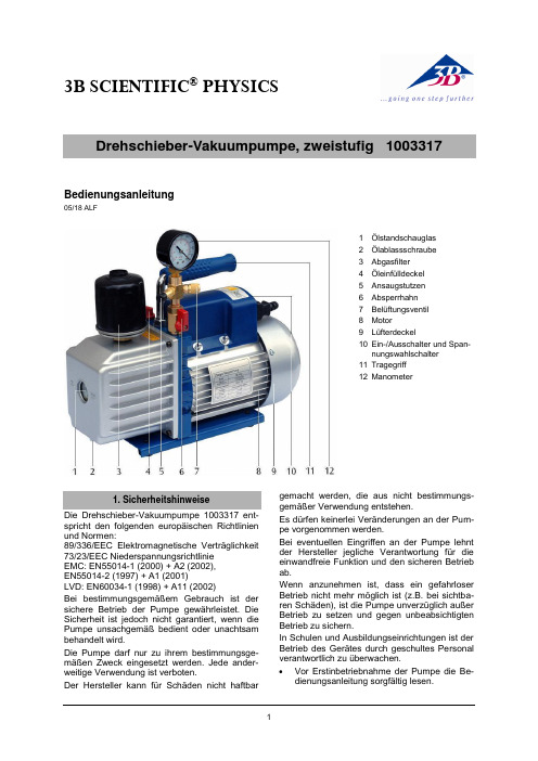
3B SCIENTIFIC ® PHYSICSBedienungsanleitung05/18 ALF1 Ölstandschauglas2 Ölablassschraube3 Abgasfilter4 Öleinfülldeckel5 Ansaugstutzen6 Absperrhahn7 Belüftungsventil8 Motor9 Lüfterdeckel10 Ein-/Ausschalter und Span-nungswahlschalter 11 Tragegriff 12ManometerDie Drehschieber-Vakuumpumpe 1003317 ent-spricht den folgenden europäischen Richtlinien und Normen:89/336/EEC Elektromagnetische Verträglichkeit 73/23/EEC Niederspannungsrichtlinie EMC: EN55014-1 (2000) + A2 (2002), EN55014-2 (1997) + A1 (2001)LVD: EN60034-1 (1998) + A11 (2002)Bei bestimmungsgemäßem Gebrauch ist der sichere Betrieb der Pumpe gewährleistet. Die Sicherheit ist jedoch nicht garantiert, wenn die Pumpe unsachgemäß bedient oder unachtsam behandelt wird.Die Pumpe darf nur zu ihrem bestimmungsge-mäßen Zweck eingesetzt werden. Jede ander-weitige Verwendung ist verboten.Der Hersteller kann für Schäden nicht haftbargemacht werden, die aus nicht bestimmungs-gemäßer Verwendung entstehen.Es dürfen keinerlei Veränderungen an der Pum-pe vorgenommen werden.Bei eventuellen Eingriffen an der Pumpe lehnt der Hersteller jegliche Verantwortung für die einwandfreie Funktion und den sicheren Betrieb ab.Wenn anzunehmen ist, dass ein gefahrloser Betrieb nicht mehr möglich ist (z.B. bei sichtba-ren Schäden), ist die Pumpe unverzüglich außer Betrieb zu setzen und gegen unbeabsichtigten Betrieb zu sichern.In Schulen und Ausbildungseinrichtungen ist der Betrieb des Gerätes durch geschultes Personal verantwortlich zu überwachen.Vor Erstinbetriebnahme der Pumpe die Be-dienungsanleitung sorgfältig lesen.∙Sicherstellen, dass der Spannungswahl-schalter auf die örtlich übliche Netzspan-nung eingestellt ist.∙Pumpe nur an Steckdosen mit geerdetem Schutzleiter anschließen.∙Pumpe nur durch eine Elektrofachkraft öff-nen bzw. reparieren lassen. Vor Durchfüh-rung einer der genannten Tätigkeiten immer die Netzverbindung durch Ziehen des Ste-ckers trennen.∙Bei Stromausfall die Pumpe aus Sicher-heitsgründen abschalten.Die Drehschieber-Pumpe 1003317 dient zur Evakuierung von Rezipienten bei der Durchfüh-rung von Vakuumexperimenten. Sie ist nicht zur industriellen Nutzung bestimmt.Die Pumpe ist eine leistungsstarke, kompakte, zweistufige, ölgedichtete Drehschieber-Vakuumpumpe. Sie ist mit thermischem Über-lastschutz und einem Abgasfilter zur Reduzie-rung des Ölnebels im Abgas, einem Manometer und einem Belüftungsventil ausgestattet.Aus Transportgründen wird die Pumpe ohne Ölfüllung ausgeliefert. Eine Flasche Öl, ausrei-chend zur Erstbefüllung; befindet sich im Liefer-umfang.Die Pumpe verfügt über einen Spannungswahl-schalter (siehe Fig. 1), so dass sie bei Netz-spannungen von 110 V oder 230 V plus oder minus 10 % betrieben werden kann.Betriebsspannung: 110 – 120 V, 60 Hz220 – 240 V, 50/60 Hz Saugvermögen: 100 l/min Enddruck: 0,003 hPa Motorleistung: 245 WÖlfüllmenge: 350 ml Manometer: 0 – 1000 mbar Schlaucholive: 10 mm dia. Abmessungen: ca. 335x138x250 mm3 Gewicht: ca. 11 kg Umgebungstemperatur: ca. 5° – 40° C Lagertemperatur: -20…70°CRel. Luftfeuchtigkeit: < 85%ohne Kondensation Verschmutzungsgrad: 2Schutzart: IP20Sicherung:20 A, flink 4.1 Allgemeine Hinweise∙Nach dem Auspacken das Verpackungsma-terial (Beutel, Kartons, Styropor) an einem für Kinder unzugänglichen Ort lagern.∙Vor Inbetriebnahme der Pumpe prüfen, ob das Typenschild angebracht ist. Fehlt es, die Pumpe nicht in Betrieb nehmen und den Vertreiber informieren.∙Falls die Pumpe zurück zum Vertreiber ge-schickt wird (z.B. zur Reparatur), Öl ablassen. ∙Zur Entsorgung des Öls die örtlichen Vor-schriften beachten.4.2 Vor der Inbetriebnahme∙Pumpe auf eine waagrechte, stabile Unter-lage stellen.∙Verbindung zur Netzspannung noch nicht her-stellen.∙Überprüfen, ob der Spannungswahlschalter in der richtigen Stellung steht und sicherstel-len, dass sich der Netzschalter in der “Aus”-Position befindet.Fig. 1 A Spannungswahlschalter, B Netzschalter,C Steckerbuchse∙Öleinfülldeckel abschrauben und so viel Öl einfüllen, bis es am unteren Rand des Öl-standschauglas sichtbar ist. An Hand der technischen Daten die richtige Ölfüllmenge der Pumpe überprüfen.∙Öleinfülldeckel wieder einschrauben, Ab-deckkappe des Ansaugstutzens abnehmen und Absperrhahn öffnen.∙Motor einschalten.∙Wenn die Pumpe ruhig läuft, Abdeckkappe des Ansaugstutzens wieder aufsetzen und Ab-sperrhahn schließen. Abhängig von der Raum-temperatur dauert dies ca. 2 bis 30 Sekunden. ∙Nach ca. 1 Minute Laufzeit den Ölstand am Ölstandschauglas auf korrekten Stand über-prüfen. Der Ölstand sollte auf Höhe der Öl-standlinie am Schauglas sein. Gegebenen-falls Öl nachfüllen.Hinweis:Ist der Ölstand zu niedrig, kommt es zu einer Verminderung der Pumpleistung. Zu viel Öl kann dazu führen, dass Öl durch den Abgasfilter austritt.4.3 Abschalten der PumpeUm die Lebensdauer der Pumpe zu verlängern und gutes Anspringen zu fördern, sollten folgen-de Schritte beim Abschalten der Pumpe befolgt werden.∙Absperrhahn schließen.∙Vakuumschlauch entfernen.∙Pumpe abschalten und Absperrhahn für einige Sekunden öffnen, um etwaiges Vaku-um in der Pumpe auszugleichen.∙Abdeckkappe auf den Ansaugstutzen set-zen, um das Eindringen von Fremdkörpern zu vermeiden.4.4 Abpumpen von kondensierbaren Dämp-fenWerden kondensierbare Gase und Dämpfe ab-gepumpt, vermischen sich diese bzw. ihre Kon-densate mit dem Öl. Dadurch verschlechtern sich die technischen Parameter der Pumpe.∙Wenn die Zusammensetzung des abzu-pumpenden Gases nicht bekannt ist und Kondensation in der Vakuumpumpe nicht ausgeschlossen werden kann, die Pumpe mit geöffnetem Belüftungsventil betreiben.4.5 Wartung4.5.1 VakuumpumpenölZur Erreichung der optimalen Pumpleistung ist der Typ und der Zustand des verwendeten Pumpenöls entscheidend. Es sollte nur Vaku-umpumpenöl verwendet werden, dessen Zu-sammensetzung höchste Viskosität bei normaler Lauftemperatur gewährleistet und den Start bei tieferen Temperaturen verbessert.4.5.2 Ölwechsel∙Vor dem Ölwechsel sicherstellen, dass die Pumpe auf Betriebstemperatur ist.∙Pumpe vom Netz trennen.∙Ölablassschraube entfernen und ver-schmutztes Öl in einem Behälter auffangen.Dabei darauf achten, dass die Dichtung nicht verloren geht.∙Zur Entsorgung des Öls die örtlichen Vor-schriften beachten.Das Öl kann auch bei laufender Pumpe mit ge-öffnetem Absperrhahn und mit einem Tuch teil-weise abgedecktem Abgasfilter abgelassen werden. Bei dieser Methode darf die Pumpe aber nicht länger als 20 Sekunden laufen.∙Wenn kein Öl mehr abfließt, Pumpe kippen, um den Rest des Öls zu entfernen.∙Ölablassschraube wieder einschrauben.∙Öleinfülldeckel abschrauben und neues Vakuumöl einfüllen, bis es am unteren Randdes Ölstandschauglas sichtbar ist.∙Sicherstellen, dass der Absperrhahn ge-schlossen ist, bevor die Pumpe in Betrieb genommen wird.∙Pumpe ca. 1 Minute laufen lassen, dann den Ölstand überprüfen.∙Befindet sich der Ölstand unter der Ölstandlinie am Schauglas, bei laufender Pumpe langsam Öl nachfüllen bis es die Ölstandlinie erreicht.∙Öleinfülldeckel wieder aufschrauben, sicher-stellen, dass der Absperrhahn geschlossen ist und die Ölablassschraube fest sitzt. Wenn das Öl stark mit Ölschlamm verschmutzt ist, kann folgende Methode benutzt werden, um das Öl zu entfernen.∙Pumpe laufen lassen, bis sie Betriebstempe-ratur erreicht hat.∙Bei laufender Pumpe Ölablassschraube entfernen. Dabei darauf achten, dass die Dichtung nicht verloren geht.∙Abgasfilter mit einem Tuch teilweise abde-cken.Dadurch wird Druck im Ölbehälter aufgebaut, der den Ölschlamm herausdrückt.∙Pumpe abschalten, wenn kein Öl mehr fließt.∙Prozedur wiederholen, bis die Verschmut-zung beseitigt ist.∙Ölablassschraube wieder einschrauben und die korrekte Menge neues Öl einfüllen.4.5.3 Entwässerung des Pumpenöls Kondensate können sich in der Pumpe ange-sammelt haben, wenn:-die Pumpe neu ist.-längere Stillstandzeiten auftraten.-die Wasserdampfverträglichkeit der Pumpe überschritten wurde.∙Pumpe ca. 30 Minuten bei geschlossener Ansaugöffnung und geöffnetem Belüftungs-ventil laufen lassen.5.1 Pumpe springt nicht an∙Überprüfen, ob der Spannungswahlschalter in der richtigen Position steht.5.2 Öl läuft aus∙Überprüfen, ob das ausgelaufene Öl keine Restansammlung von Schüttverlust etc. ist. Falls das Leck an der Pumpe auftritt, muss ent-weder die Gehäusedichtung oder die Wellen-dichtung ausgewechselt werden.3B Scientific GmbH ▪ Rudorffweg 8 ▪ 21031 Hamburg ▪ Deutschland ▪ ∙Pumpe zwecks Reparatur an den Hersteller schicken.Falls die Ölablassschraube undicht ist,∙ Ölablassschraube mit einem handelsübli-chen Dichtungsring abdichten.5.3 Verminderte Pumpenleistung∙ Sicherstellen, dass das Manometer und alleVerbindungsleitungen in gutem Zustand und dicht sind.∙ Zur Überprüfung der Dichtheit Vakuumpum-penöl auf die vermuteten Stellen an der Pumpe und den Zuleitungen auftragen. Die Pumpleistung steigt kurz an, da das Öl als Dichtmittel wirkt.∙ Sicherstellen, dass das Pumpenöl sauber ist. Eine stark verschmutzte Pumpe könnte mehrere Ölspülungen benötigen.∙ Sicherstellen, dass der Ölstand korrekt ist. Zur Erreichung einer maximalen Pumpleistung muss der Ölstand bei laufender Pumpe auf Hö-he der Ölstandlinie am Schauglas sein. ∙ Nicht zuviel Öl einfüllen.Bei Betriebstemperatur dehnt sich das Öl aus und ein höherer Ölstand wird angezeigt als bei nicht lau-fender Pumpe.∙ Um den Ölstand zu überprüfen, Pumpe beigeschlossenem Absperrhahn laufen lassen. ∙ Ölstand überprüfen und gegebenenfalls Ölnachfüllen.5.4 Automatisches AbschaltenDie Pumpe ist mit einem thermischen Überlast-schutz ausgestattet. Bei zu hoher Umgebungs-temperatur schaltet die Pumpe automatisch ab. ∙ Netzspannung nicht sofort abschalten.Falls die Pumpe nach 3 Minuten nicht wieder automatisch anläuft,∙ Pumpe durch Herabsetzen der Umgebungs-temperatur abkühlen lassen und so die Le-bensdauer der Pumpe verlängern.∙ Die Verpackung ist bei den örtlichen Recyc-lingstellen zu entsorgen.∙Sofern das Gerät selbst verschrottet werden soll, so gehört dieses nicht in den normalen Hausmüll. Bei Nutzung in Privathaushalten kann es bei den örtli-chen öffentlich-rechtlichen Entsor-gungsträgern entsorgt werden.∙Geltende Vorschriften zur Entsorgung von Elektroschrott einhalten.。
空气质量检测仪器操作说明书
空气质量检测仪器操作说明书一、操作前的准备1. 检查仪器在操作之前,务必检查空气质量检测仪器的外观是否完好,是否有损坏或松动的零件。
如发现有问题,请及时联系维修人员或供应商。
2. 电源接入将仪器的电源线插入电源插座,并确保插头连接牢固。
然后打开电源开关,待仪器启动完毕后,进行下一步操作。
3. 校准仪器为了确保测试结果准确可靠,请在操作之前对仪器进行校准。
具体校准方法请参考仪器附带的校准指南。
二、操作步骤1. 打开仪器按下电源按钮,等待仪器启动。
过程可能需要几秒钟,请耐心等待。
2. 选择测试模式根据需要进行选择测试模式。
仪器通常具有多种测试模式,如室内空气质量、室外空气质量、PM2.5检测等。
根据实际情况选择相应的模式。
3. 放置仪器将仪器放置在待测区域的合适位置。
确保仪器与外部物体之间保持一定的距离,以避免测量结果受到干扰。
4. 开始测试按下“开始”按钮或相关的测试指令,仪器将开始采集数据并进行分析。
此时请保持待测区域环境的相对稳定,以确保测试结果的准确性。
5. 数据记录仪器会自动记录测试数据,并将其显示在仪器屏幕上。
同时,也可以通过连接电脑或其他设备,将数据保存或传输至其他平台。
6. 停止测试测试结束后,按下“停止”按钮或相关指令,仪器停止采集数据并进行处理。
此时可以关闭仪器或进行其他操作。
三、注意事项1. 环境条件在使用空气质量检测仪器时,请确保环境条件良好。
避免在恶劣的天气或污染严重的场所进行测试,以免影响测试结果。
2. 避免干扰在测试过程中,要避免与外部光线、电磁场或其他干扰源接触。
这些干扰可能影响仪器的准确性。
3. 定期维护为了保证仪器的正常运行和测试准确性,建议定期进行维护和保养。
可以按照仪器使用手册中的要求进行维护,也可以联系供应商进行维护服务。
4. 安全使用在操作仪器时,请注意安全。
避免将仪器放置在易燃、易爆或高温等危险环境下,以免发生意外。
五、技术支持如在使用过程中遇到问题,或需要进一步的技术支持,请联系供应商或仪器厂家。
3B Scientific GmbH 空气实验室平台说明书

3B SCIENTIFIC ® PHYSICS1Istruzioni per l'uso09/16 ALF∙Proteggere la superficie del piatto per esperi-menti che richiedono il vuoto da umidità, so-stanze chimiche e azioni meccaniche in modo tale da garantirne l’ermeticità.Se la campana da vuoto è difettosa puòimplo-dere.∙Prima di eseguire l’esperimento verificareche lacampana da vuoto non sia danneg-giata (l’eventuale aria all’interno non compro-mette la sicurezza di funzionamento).3 Passaggio di corrente con cavi di col- legamento e jack di sicurezza4 Foro centrale con filettatura M125 Disco di tenuta in gomma6 Spina di sicurezza da 4 mm7 2 rubinetti per l’attacco del tubo e per la ventilazione8 Treppiede di supporto con piatto me-tallico3B Scientific GmbH ▪ Ludwig -Erhard-Str. 20 ▪ 20459 Amburgo ▪ Germania ▪ Con riserva di modifiche tecniche © Copyright 2023 3B Scientific GmbHIl piatto per esperimenti che richiedono il vuoto e la campana da vuoto servono per il montaggio di un recipiente sotto vuoto per esperimenti nel set-tore del vuoto fine e grossolano.2.1 Piatto per esperimenti che richiedono ilvuoto Il piatto per esperimenti che richiedono il vuoto è un piatto metallico con disco di tenuta in gomma poggiato su un treppiede e dotato di due rubinetti per l’attacco del tubo lato pompa e per la ventila-zione. Un foro centrale con filettatura M12 serve per il fissaggio di appare cchi sperimentali. L’ali-mentazione di corrente degli apparecchi speri-mentali avviene mediante un passaggio di cor-rente a tenuta di pressione a vuoto con jack di sicurezza da 4 mm e due cavi con spine di sicu-rezza da 4 mm.2.2 Campana da vuotoCampana da vuoto di vetro con pomello e flangia liscia per l’applicazione sul piatto. Per esperi-menti che richiedono il vuoto.Piatto per esperimenti che richiedono il vuoto Diametro: 250 mm Altezza: 90 mmPassaggio di corrente: 2 poli con jack di sicu-rezza da 4 mmAlimentazione di corrente: mediante 2 cavi lunghica. 1 m con spine di si-curezza da 4 mmLimitazioni elettriche: max: 48 V, max. 12 A Attacco per il vuoto: 2 nippli per tubi 12 mm e 8 mm Ø Campana da vuoto Diametro interno: 190 mm Altezza:220 mmPer l'esecuzione degli esperimenti sono inoltre necessari i seguenti apparecchi:1 Pompa per vuoto a palette, due stadi 1003317 1 Tubo di gomma per vuoto 8 mm 1002619∙Prima di eseguire l’esperimento verificareche la campana da vuoto non presenti even-tuali danni.∙ Accertarsi che il disco di tenuta e il bordo li-scio della campana non siano impolverati. ∙All'inizio dell'esperimento, premere la cam-pana da vuoto contro il piatto da vuoto fino a quando la pressione dell'aria esterna non ga-rantisce una pressione di contatto sufficiente contro la guarnizione in gomma. Rilasciare quindi la campana da vuoto.∙ Se la maniglia della valvola è rivolta verso il basso, entrambi i rubinetti sono chiusi.∙Se la maniglia della valvola punta in direzione di un rubinetto, questo è aperto e il rubinetto opposto è chiuso.∙Dopo aver eseguito l’esperimento disattivare la pompa, chiudere la valvola per vuoto e im-mettere aria nel recipiente.。
空气能热水器实验台操作规程
空气能热水器实验台操作规程目的指导和规范测试人员的检验作业。
适用范围空气能热水器实验测试。
操作规程一、开机前安装准备1、水管连接在热水器进水口处(即蓝色堵帽侧)连接一个泄压安全阀(CODE35006013104)(箭头指向水流的方向),泄压安全阀上必须连接导流管,热水管应从出水口(红色堵帽侧)连接,导流排水管要保持与大气相通,排水管要以一种连续向下的方式安装在无霜的环境中。
注意:正常使用情况下,应定期打开安全阀手柄以去掉碳酸钙沉淀并证明安全阀没有堵塞。
将手柄向上扳至水平表明已打开,如有水流出则安全阀正常工作,如无水流出请与当地客户服务部联系。
2、系统冷媒管的连接2.1 根据下面方法连接冷媒管2.1。
1 先连接水箱,后连接室外机a 配管弯曲排布要仔细,不要损坏配管及配管保护层;b 在拧紧扩口螺母之前,在管道扩口处外表面和连接螺母锥面上涂抹冷冻机油,并先用手拧紧3~4圈;c 连接或拆下管道时,必须同时使用两个扳手;d 请不要让连接管的重量由水箱接口处承受,因为水箱接口处管道如果过重,会变形进而影响制热水的效果或者导致泄漏。
2。
1.2 室外机的截止阀应该完全关闭(如出厂状态),每次连接应该从截止阀处拧开螺母,即刻接上扩口管(5分钟内),截止阀处的螺母拆下后放置时间过长时,灰尘和其他杂物可能进入管道系统中,以后会引起故障。
2。
1.3 冷媒连接管解开方法沿逆盘管弯曲方向缓慢把管端弯直,切不可抓住盘管两端用力拉扯。
注意:● 冷媒管可挠部分的管道应注意事项:a 弯曲角度不要超过90度;b 弯曲处应该尽可能处于管长中心,弯曲半径越大越好;c 不要把可挠管前后弯曲3次以上。
● 使用市场买来的铜管时,一定要使用同样的绝热保温材料(厚度12mm以上)。
3、管道连接制冷剂泄漏的主要原因是扩口作业的缺陷造成的,因此在安装连接管前应仔细检查扩口的质量,如果扩口存在缺陷,应按下列程序进行正确的扩口作业。
3。
1. 管道截割使用截管器正确地截割连接管。
TG209F3操作规程

NETZSCH TG 209 F3 操作规程一、操作条件1. 实验室要求温度恒定,电源稳定220V,10A。
实验室应尽量远离振动源及大的用电设备, 室内配备空调, 以保证温度恒定。
2. 计算机在仪器测试时,最好不要上网或运行系统资源占用较大的程序。
3. 保护气体(Protective):保护气体是用于在操作过程中对加热元件进行保护,以保证其使用寿命。
Ar、N2、He 等惰性气体均可用作保护气体。
保护气体输出压力应调整为0.03Mpa,流速恒定为10-20ml/min。
开机后,保护气体开关应始终为打开状态。
4. 吹扫气体(Purge1 / Purge2):吹扫气体在样品测试过程中,用作为气氛气、或反应气。
一般采用惰性气体,也可用氧化性气体(如:空气、氧气等)或还原性气体(如:CO、H2等)。
但应慎重考虑使用氧化、还原性气体作气氛气,特别是还原性气体,会缩短样品支架热电偶的使用寿命,还会腐蚀仪器上的零部件。
吹扫气体输出压力应调整为0.03Mpa,流速≤100ml/min,一般情况下为20~30ml/min。
测试过程中如果被测样品可能发生分解反应时,吹扫气流速应随之加大,以保证分解产物的及时排出,避免污染炉体及传感器。
5. 动态测量模式、静态测量模式:在有吹扫及保护气体时的测量为动态测量模式,否则为静态测量模式。
为了延长仪器寿命,保护仪器部件,应尽可能使用在惰性气氛下的动态模式进行测量,慎重考虑静态测量模式。
6. 恒温水浴:恒温水浴是用来保证测量天平工作在一个恒定的温度下。
一般情况下,恒温水浴的水温调整为至少比室温高出5︒C。
7. 真空泵:为了保证样品测试中不被氧化或与空气中的某种气体进行反应,需要真空泵对测量管腔进行反复抽真空并用惰性气体置换。
一般置换两到三次即可。
二、样品准备1. 根据样品材料选择合适的坩埚(常规使用铝坩埚。
如改变了坩埚种类,需在软件的仪器设置项目中作相应设定)。
2. 检查并保证测试样品及其分解物绝对不能与测量坩锅、样品支架、热电偶发生反应。
- 1、下载文档前请自行甄别文档内容的完整性,平台不提供额外的编辑、内容补充、找答案等附加服务。
- 2、"仅部分预览"的文档,不可在线预览部分如存在完整性等问题,可反馈申请退款(可完整预览的文档不适用该条件!)。
- 3、如文档侵犯您的权益,请联系客服反馈,我们会尽快为您处理(人工客服工作时间:9:00-18:30)。
ZKY-RJ
空气热机实验仪
软件操作说明书
成都世纪中科仪器有限公司
第一章概述 1
1.1软件的功能 1
1.2本系统的运行环境。
1
1.2.1 硬件运行环境 1
1.2.1 软件运行环境 1
1.2.3本系统的安装方法。
2
第二章操作方法 2
2.1具体操作说明 2
2.1.1 系统初始条件 2
2.1.2 系统启动 2
2.1.3 各功能操作说明 3
第一章概述
1.1软件的功能
本软件能够将空气热机实验装置的气缸容积及压力随转动的信号盘的转角(即汽缸中的飞轮盘运动的角度)以实时地显示出来。
同时能够自动得到气缸运动一周的容积-压力变化曲线图,并自动计算出该容积-压力变化曲线图所围成的面积。
与此同时,能够得到热机实验仪上显示的所有数据,如T1和T2和ΔT、热机转速。
1.2本系统的运行环境
1.2.1 硬件运行环境
CPU:PⅣ 400MHz 以上;
内存:256MB以上;
显卡:支持800Χ600以上;
RS232串行口。
1.2.1 软件运行环境
操作系统: WindowsNT4.0或WindowsXP以上;
1.2.3本系统的安装方法
本系统的安装程序为一张光盘。
安装本系统时,需运行Setup.exe,然后根据安装向导的提示完成安装即可。
第二章操作方法
2.1具体操作说明
2.1.1 系统初始条件
初始条件:在空气热机实验仪已经开启,空气热机实验装置正常运转
2.1.2 系统启动
在空气热机实验仪已经开启,空气热机实验装置正常运转后,用键
盘或鼠标激活“开始 → 程序 → 中科教仪-空气热机 →空气热机实验”(具体操作方法请查阅有关WINDOWS95、WINDOWS98或WINNT的相关章
节),系统会弹出一个系统登录窗口。
在“用户”框中输入您的登录名称,在“密码”框中输入密码,然后按下“登录”按钮(或直接回车),系统会校验您的口令是否合法,以决定您是否有使用本系统的权限。
如口令合法,您就登录成功,进入系统(主窗口如下图所示)。
按下“退出”按钮,系统会放弃登陆,退出系统登录窗口。
2.1.3 各功能操作说明
系统总共有五个大的功能模块,分别为:
● 系统管理:主要包括通讯参数设置、实验资料管理等功能,只
有具备系统管理员权限的操作用户才具有操作这些功能的权限。
● 资料查阅:主要包括实验原理、实验内容、背景资料等与实验有关的信息查阅功能,以便于随时进行查阅。
● 数据通讯:主要是实验的操作包括开始实验、启动测试和结束测试3个功能。
● 窗口管理:主要包括子窗口的排列方式和在个字窗口之间进行切换的功能。
● 帮助信息:系统帮助和版本信息。
2.1.
3.1 系统管理
A. 通讯参数设置:主要对计算机与实验设备之间的通讯参数
进行设置
通讯端口:指的是实验装置与计算机所连接的串口;在
仪器全部连接正确并接通电源的条件下,可以点击旁边
的“自动找到通信端口”来找到当前的连接端口,找到后
重新启动软件就可以使用了。
通讯波特率:指的是进行实验时,计算机与实验设备之
间通讯的速度。
B. 实验资料管理:维护与实验有关的实验资料;
删除实验资料:首先选择资料类型(用鼠标选择窗口右
边的选项按钮),然后单击“删除”按钮即可删除该项资
料的内容;
添加实验资料:首先选择资料类型,如果该项已经有资
料,那么必须先删除当前的资料,然后单击“打开”按钮
打开要添加的超级文本,再单击“保存”,系统会提
示‘该文件是否包含有图片’,如果选择“是”则系统要求
打开图片文件,选择完成后按回车键即可保存该项资
料。
C. 关闭所有窗体:关闭所有打开的子窗体。
2.1.
3.2 资料查阅
A. 实验原理:查阅实验原理;
单击菜单上的“资料查阅-实验原理”(或单击“原理”快捷键)
即可查阅实验原理的信息。
B. 实验内容:查阅实验内容;
单击菜单上的“资料查阅-实验内容”(或单击“内容”快捷键)
即可查阅实验内容的信息。
C. 背景资料:查阅与实验有关的背景资料;
单击菜单上的“资料查阅-背景资料”(或单击“资料”快捷键)
即可查阅背景资料的信息。
2.1.
3.3 数据通讯
A. 开始实验:该功能主要是启动系统通讯端口,并显示如下
窗口图像,一旦选中按钮“开始实验”,则将启动通讯端口,
并接收从端口中传来的空气热机实验数据,显示在窗口
中,“显示实验数据P-V图形”子窗口是在“显示实验数据曲
线”子窗口中选中按钮“观察P-V图”后显示的子窗口。
B. 暂停:该功能主要是停止系统接收空气热机实验发来的有
关数据,并保留最后收到的数据图形内容,以供研究。
在此时,当鼠标放在显示的图像窗口中时,本软件主窗口的底部将提示有关的图形操作热键“按←↑→↓、Home/End和
PageUp/PageDown键移动曲线;按Shift + ←↑→↓键缩放曲线,按空格键还原;按Ctrl + ←↑→↓键沿轴线方向缩放曲线”,根据这些提示,进行热键操作,将可以更加细致地观察相关的曲线内容。
只要重新选中“启动”按钮,则又可以重新开始收取空气热机实验仪的数据。
C. “结束测试”或“停止”:此时将关闭显示的空气热机实验仪
图形曲线,并关闭连接该实验仪通讯端口。
只有重新选中在水平菜单“数据通讯”中菜单“开始实验”才能重新接收来自空气热机实验仪的数据并显示图形出来。
2.1.
3.4 窗口管理
A 层叠:按层叠方式排列所有子窗口。
B 横排:按横向排列的方式排列所有子窗口。
C 竖排:按竖向排列的方式排列所有子窗口。
D 全部最小化:最小化所有子窗口。
F 全部重排:重新排列所有子窗口。
2.1.
3.5 帮助信息
A 帮助:系统的使用说明。
B 关于:显示系统的版本信息。