无线通信网络第5章-天线与传播
通信天线_精品文档

通信天线1. 简介通信天线是一种用于发送和接收无线电信号的设备。
它是通信系统中至关重要的组成部分,用于实现无线电频段上的信息传输。
通信天线具有不同的类型和设计,可根据不同的应用需求选择。
2. 通信天线的原理通信天线工作的原理是利用电磁场传输和接收无线电信号。
当电磁波从信号源发射时,通信天线接收到这些信号并将其转换为电信号。
同样地,通信天线也可以将电信号转换为无线电信号并向外发射。
通信天线的原理主要基于麦克斯韦方程组,其中最为重要的是法拉第电磁感应定律和安培环路定律。
通过这些定律,通信天线能够实现信号的传输和接收。
3. 通信天线的类型3.1 定向天线定向天线是一种能够将信号束聚到特定方向的天线。
它主要用于需要在特定方向上进行远距离传输或接收的应用中,如雷达系统、卫星通信等。
定向天线具有较高的增益和较小的辐射角度。
3.2 Omni天线Omni天线是一种能够在全方向上均匀辐射或接收信号的天线。
它主要用于无线通信系统中,如Wi-Fi路由器、蜂窝网络基站等。
Omni天线的辐射模式呈360度水平覆盖,但在垂直方向上有一定的方向性。
3.3 扁平天线扁平天线是一种相对较薄且紧凑的天线设计。
它常用于一些对天线尺寸要求较小的应用,如移动通信设备、车载通信设备等。
扁平天线通常具有宽频段特性和低辐射角度。
3.4 天线阵列天线阵列是由多个天线元件组成的阵列结构。
通过控制这些天线元件的相位和幅度,天线阵列能够实现波束的形成和方向的调节。
天线阵列常用于通信系统中的干扰抑制、方向搜索等应用。
4. 通信天线的选择与优化在选择和优化通信天线时,需要考虑以下几个要素:4.1 频率范围通信天线的频率范围应与设备所需的无线电频段相匹配。
不同的应用场景对频率范围的要求有所区别,因此在选择通信天线时需要确保其能够工作在所需的频率范围内。
4.2 增益增益是衡量天线指向性和接收能力的重要参数。
通信系统中通常希望通过天线实现信号的远距离传输和接收,因此较高的增益对于提高系统性能至关重要。
无线通信网络中的多天线技术
无线通信网络中的多天线技术多天线技术(MIMO)是无线通信领域中一种重要的技术,通过利用多个发射天线和接收天线,以提高信号传输的可靠性和容量。
本文将介绍多天线技术的原理、应用场景以及未来发展方向。
一、多天线技术的原理多天线技术利用了信号传播时的多径效应。
当信号传播到接收端时,会经历多条不同路径的传播,每一条路径都会产生一个信号,这些信号相互干扰叠加,造成信号衰落和失真。
多天线技术通过在发送端和接收端增加多个天线,可以获取多个信号样本,通过信号处理算法进行合并,以提高信号质量和传输速率。
二、多天线技术的应用场景1. 无线局域网(WLAN)多天线技术在无线局域网中被广泛应用。
传统的无线局域网系统通过单一天线与用户进行通信,受限于信号叠加和干扰,传输速率有限。
而引入多天线技术可以在一定程度上克服这些问题,提高信号质量和传输速率。
目前,IEEE 802.11n和IEEE 802.11ac等无线局域网标准已经引入了多天线技术,实现了更高的传输速率和稳定性。
2. 移动通信系统移动通信系统是多天线技术的重要应用领域之一。
在LTE(Long Term Evolution)等移动通信系统中,多天线技术被用于信道估计、信号检测和信号干扰抵消等关键环节。
多天线技术可以提高信道容量和频谱效率,同时可以减少信号传输中的误码率。
3. 无线传感器网络无线传感器网络是由大量分布在空间中的传感器节点组成的网络,用于感知和监测环境中的物理参数。
多天线技术可以提高传感器节点之间的通信质量,减少信号衰落和干扰,并且可以增加网络的范围和覆盖面积。
对于无线传感器网络应用来说,多天线技术的引入有助于提高网络的可靠性和稳定性。
三、多天线技术的发展方向1. 大规模MIMO大规模MIMO是多天线技术的一种发展方向,它通过在基站端使用大量的天线,同时服务多个用户,以提高信号传输的容量和覆盖范围。
大规模MIMO技术还能够有效抵消信号的干扰和衰落,提高系统的性能。
毕业论文-WIFI天线设计

毕业论文-WIFI天线设计齐齐哈尔大学无线通信(论文)题目 WIFI天线设计专业班级通信工程 084 班学生姓名李敏代兴利陈树家学号 2008132111 2008132117 2008132003指导教师赵岩2011年12月20日I齐齐哈尔大学无线通信摘要在无线网络迅速发展的今天,天线的地位及其应用被人们日益重视。
本文系统的介绍WIFI天线制作方法,理论分析依据,及其制作过程中的技术要求。
本文具体内容包涵WIFI知识, WIFI是种短程无线传输技术。
具体理论分析计算制作WIFI天线形状、尺寸大小及其选用材料,具体制作WIFI天线的过程。
及其测试WIFI天线性能,对比系统自带天线。
包涵制作心得及其制作技巧,此天线原理简单,制作成功率高,是各位无线网络DIY爱好者初级制作首选。
关键词:WIFI天线;无线网络;WIFI天线制作I齐齐哈尔大学无线通信ABSTRACTIn today's rapid development of wireless networks, antenna and its applications is increasing attention on the status of. Method for making this system to introduce WIFI antenna, theoretical analysis based on, and in the process of making technology requirements.Knowledge of specific content in this article include WIFI, WIFI is kind of short range wireless transmission technology. Analysis and calculation of specific theories make WIFI antenna selection of shapes, sizes and materials, the concrete process of making WIFI antenna. And testing WIFI antenna performance, contrast with antenna system. Excuse making experience and production skills, this antenna simple in principle, make a highly successful, are you DIY enthusiasts primary production preferred wireless network.Key words:WIFI antenna; wireless signal; WIFI antenna manufacture II齐齐哈尔大学无线通信目录摘要 ..................................................................... (I)ABSTRACT ........................................................... ...................................................... II 目录 ..................................................................... ................................................... III 第1章引言 .............................................................................................................. 1 第2章概述 ..................................................................... . (2)2.1 WIFI相关简述 ..................................................................... . (2)2.2 WIFI组建方法 ..................................................................... . (4)2.3 WIFI目前的应用 ..................................................................... (5)2.4 WIFI天线制作与测试材料及工具 (6)2.5 本设计方案思路 ..................................................................... (6)2.6 主要技术指标...................................................................... ...................... 7 第3章理论分析 ..................................................................... . (9)3.1 分析天线形状...................................................................... .. (9)3.2 天线尺寸设计...................................................................... ..................... 10 3.3 罐头盒大小设计 ..................................................................... ........................... 11 3.4 导波线路分析...................................................................... .............................. 13 第4章制作与调试 ..................................................................... (15)4.1 整体实物制作...................................................................... (15)4.2 WIFI天线调试 ..................................................................... .. (21)第5章性能测试与对比 ..................................................................... (22)5.1 系统自带天线与WIFI天线性能对比 (22)第6章制作心得 ..................................................................... ................................... 26 第7章结论 ..................................................................... .. (27)III齐齐哈尔大学无线通信第1章引言WIFI全称Wireless Fidelity,又称802.11b标准,是IEEE定义的一个无线网络通信的工业标准(IEEE802.11)。
无线网络WiFi天线原理
无线网络WiFi天线原理1.7.2 高增益栅状抛物面天线从性能价格比出发,人们常常选用栅状抛物面天线作为直放站施主天线。
由于抛物面具有良好的聚焦作用,所以抛物面天线集射能力强,直径为 1.5 m 的栅状抛物面天线,在900兆频段,其增益即可达 G = 20dBi。
它特别适用于点对点的通信,例如它常常被选用为直放站的施主天线。
抛物面采用栅状结构,一是为了减轻天线的重量,二是为了减少风的阻力。
抛物面天线一般都能给出不低于 30 dB 的前后比,这也正是直放站系统防自激而对接收天线所提出的必须满足的技术指标。
1.7.3 八木定向天线八木定向天线,具有增益较高、结构轻巧、架设方便、价格便宜等优点。
因此,它特别适用于点对点的通信,例如它是室内分布系统的室外接收天线的首选天线类型。
八木定向天线的单元数越多,其增益越高,通常采用 6 - 12 单元的八木定向天线,其增益可达 10-15dBi。
1.7.4 室内吸顶天线室内吸顶天线必须具有结构轻巧、外型美观、安装方便等优点。
现今市场上见到的室内吸顶天线,外形花色很多,但其内芯的购造几乎都是一样的。
这种吸顶天线的内部结构,虽然尺寸很小,但由于是在天线宽带理论的基础上,借助计算机的辅助设计,以及使用网络分析仪进行调试,所以能很好地满足在非常宽的工作频带内的驻波比要求,按照国家标准,在很宽的频带内工作的天线其驻波比指标为VSWR ≤ 2 。
当然,能达到VSWR ≤ 1.5 更好。
顺便指出,室内吸顶天线属于低增益天线, 一般为G = 2 dBi。
1.7.5 室内壁挂天线室内壁挂天线同样必须具有结构轻巧、外型美观、安装方便等优点。
现今市场上见到的室内壁挂天线,外形花色很多,但其内芯的购造几乎也都是一样的。
这种壁挂天线的内部结构,属于空气介质型微带天线。
由于采用了展宽天线频宽的辅助结构,借助计算机的辅助设计,以及使用网络分析仪进行调试,所以能较好地满足了工作宽频带的要求。
顺便指出,室内壁挂天线具有一定的增益,约为G = 7 dBi。
无线通信网络天线与传播
Beam width (or half-power beam width)
Measure of directivity of antenna
Reception pattern
Receiving antenna’s equivalent to radiation pattern
In two-way communication, the same antenna can be used for transmission and reception
Radiation Patterns
Radiation pattern
Graphical representation of radiation properties of an antenna
antenna)
Parabolic Reflective Antenna
Antenna Gain
Antenna gain
Power output, in a particular direction, compared to that produced in any direction by a perfect omnidirectional antenna (isotropic antenna)
Introduction
An antenna is an electrical conductor or system of conductors
Transmission - radiates electromagnetic energy into space
Reception - collects electromagnetic energy from space
《无线通信技术》课程教学大纲

无线通信技术Wireless Communication Technique课程代码:学分:2学时:32(讲课学时:32 )先修课程:模拟电子技术、高频电子线路、计算机网络技术、通信原理适用专业:通信工程、电子信息工程建议教材:《无线通信技术》布雷克科学出版社2004 年版开课系部:信息工程系一、课程的性质与任务本课程是电信专业方向的一门面向设计与应用的专业课程。
通过对本课程的学习,使学生能掌握、了解移动网络、无线接入技术、无线局域网等网络技术及无线通信技术,适应现代社会通信事业快速发展的需要,并对移动通信原理、数字移动通信系统、个人通信有较深刻的理解,成为高素质技能型专门人才,为未来参加工作、增加就业竞争力打下良好的基础。
本课程主要学习无线通信、移动通信与因特网、无线接入技术、无线局域网、WAP技术、无线寻呼、电话与因特网、蓝牙技术等内容,要求学生在学习本课程以后,从计算机网络的系统组成、组网和应用各方面理解和掌握较新的网络及无线通信技术。
二、课程的基本内容及教学要求第一部分基本概念1.教学内容(1)概论(2)无线通信简史(3)无线通信系统原理(4)信号与噪声(5)频率域(1)“融合”与无线通信2. 教学要求(1)了解无线通信简史、无线通信系统原理(2)掌握信号与噪声、频率域的基本概念3. 重点和难点重点:无线通信系统基本组成、信号与噪声、频率域难点:无线通信系统原理、频率域第二部分模拟调制方案1.教学内容(1)概论(2)幅值调制(3)抑制载波AM 系统(4)频率调制和相位调制2. 教学要求(1)了解频率调制和相位调制(2)掌握幅值调制、抑制载波AM 系统的基本概念3. 重点和难点重点:幅值调制、抑制载波AM 系统难点:频率调制和相位调制第三部分数字通信1.教学内容(1)概论(2)采样(3)脉码调制(4)增量调制(5)数据压缩2. 教学要求(1)了解增量调制、数据压缩(2)掌握采样、脉码调制的基本概念3. 重点和难点重点:采样、脉码调制难点:增量调制、数据压缩第四部分数字调制1.教学内容(1)概论(2)频移键控(FSK)(3)相移键控(PSK)(4)正交调幅(QAM)(5)多路复用与多址(6)扩频系统2. 教学要求(1)了解正交调幅(QAM) 、扩频系统(2)掌握频移键控(FSK)、相移键控(PSK) 、多路复用与多址的基本概念3. 重点和难点重点:频移键控(FSK) 、相移键控(PSK) 、多路复用与多址难点:频移键控(FSK) 、相移键控(PSK) 、多路复用与多址第五部分电话技术基础1.教学内容(1)概论(2)网络拓扑(3)本地环路及其信号(4)数字电话技术(5)电话网络信令(6)数字本地环路2. 教学要求(1)了解电话网络信令、数字本地环路(2)掌握网络拓扑、本地环路及其信号、数字电话技术的基本概念3. 重点和难点重点:网络拓扑、本地环路及其信号、数字电话技术难点:本地环路及其信号、数字电话技术第六部分传输线路与波导管1.教学内容(1)概论(2)电磁波(3)波沿传输线路的传播(4)反射与驻波(5)传输线路损耗(6)波导管2. 教学要求(1)了解电磁波、波沿传输线路的传播(2)掌握反射与驻波、传输线路损耗的基本概念3. 重点和难点重点:波沿传输线路的传播、反射与驻波、传输线路损耗难点:反射与驻波第七部分无线电传播1.教学内容(1)概论(2)自由空间传播(3)地面传播(4)卫星传播2. 教学要求(1)了解卫星传播(2)掌握自由空间传播、地面传播的基本概念3. 重点和难点重点:自由空间传播、地面传播难点:卫星传播第八部分天线1.教学内容(1)概论(2)简单天线(3)天线特性(4)其他简易天线类型(5)天线阵列(6)反射器(7)蜂窝天线和PCS 天线2. 教学要求(1)了解反射器、蜂窝天线和PCS 天线(2)掌握天线特性、天线阵列的基本概念3. 重点和难点重点:天线特性、天线阵列难点:天线阵列、反射器第九部分发射机与接收机电路1.教学内容(1)概论(2)发射器(3)接收机(4)收发机2. 教学要求(1)了解发射器(2)掌握接收机、收发机的基本概念3. 重点和难点重点:接收机、收发机难点:收发机第十部分蜂窝无线电系统1.教学内容(1)概论(2)历史回顾(3)高级移动电话系统(AMPS) 介绍(4)AMPS 控制系统(5)安全与保密(6)蜂窝电话标准及工作原埋(7)小区站设备(8)利用蜂窝电话进行传真和数据通信(9)数字蜂窝系统2. 教学要求(1)了解高级移动电话系统、数字蜂窝系统(2)掌握AMPS 控制系统、小区站设备、利用蜂窝电话进行传真和数据通信的基本概念3. 重点和难点重点:AMPS 控制系统、小区站设备、利用蜂窝电话进行传真和数据通信难点:AMPS 控制系统第十一部分个人通信系统1.教学内容(1)概论(2)蜂窝系统与PCS 系统的区别(3)IS-136(TDMA)PCS(4)GSM(5)IS-95CDMAPCS(6)几种调制方案的比较(7)PCS 系统数据通信(8)测试蜂窝系统和PCS 系统2. 教学要求(1)了解IS-136(TDMA)PCS(2)掌握蜂窝系统与PCS 系统的区别,GSM 的基本概念3. 重点和难点重点:蜂窝系统与PCS 系统、GSM 、PCS 系统数据通信难点:蜂窝系统和PCS 系统第十二部分星基无线系统1.教学内容(1)概论(2)卫星轨道(3)卫星用于通信(4)卫星与转发器(5)信号与噪声计算(6)使用地球静止卫星的系统(7)使用低轨( L EO)卫星的系统(8)使用中轨(MEO) 卫星的系统2. 教学要求(1)了解IS-136(TDMA)PCS(2)掌握蜂窝系统与PCS 系统的区别,GSM 的基本概念3. 重点和难点重点:蜂窝系统与PCS 系统、GSM 、PCS 系统数据通信难点:蜂窝系统和PCS 系统第十三部分寻呼系统与无线数据网1.教学内容(1)概论(2)寻呼与消息系统(3)无线局域网(4)无线分组数据业务2. 教学要求(1)了解寻呼与消息系统、无线分组数据业务(2)掌握无线局域网的基本概念3. 重点和难点重点:无线局域网难点:无线分组数据业务三、实践环节的要求无实践环节四、课程学时分配课程内容讲课实验习题课讨论课课程设计上机小计基本概念 2 2 模拟调制方案 2 2 数字通信 2 2 数字调制 2 2 电话技术基础 4 4 传输线路与波导管 2 2无线电传播 4 4 天线 2 2 发射机与接收机电路 2 2 蜂窝无线电系统 2 2 个人通信系统 2 2 星基无线系统 2 2 寻呼系统与无线数据网 2 2 机动 2 2 共计32 32五、考核笔试:40%,上课出勤:15%,作业:20%,课程设计:25%六、教材与主要参考书《无线通信技术》布雷克科学出版社2004 年版《无线通信系统与技术》潘焱人民邮电出版社2011 年版制定人:审定人:批准人:。
陆地移动通信无线传播—三种传播机制
第5章陆地移动通信无线传播—三种传播机制5.1 引言为了设计高频谱效率的移动通信系统,就需要对无线传播特性有较详细的了解。
移动无线通信的传播特性除了和工作频率有关以外,还和移动无线环境包括地形起伏与周围建筑物等、天线高度以及传播情况,例如视距(line of sight,LOS)无线链路还是非视距(NLOS)无线链路、反射、绕射/散射有极大的关系。
对在这样复杂环境中传播的信号变化的精确特征描述是一项非常艰巨的任务。
在本节中,重点是讨论陆地移动无线通信的传播特性,其中许多概念也将适用于其它类型的无线通信。
前面我们已经讨论了自由空间、平坦地面,刃锋绕射等传播模式。
这些模式属于确定性方法,它们是通过电磁理论的直接求解或射线理论的近似求解所得到的无线链路中的传播情况,虽然它们只适用于非常简单的环境,但是它们在提供基本的传播机理时是有用的。
另一类传播模式是通过大量实验结果得到的用曲线和/或公式描述的经验模式,如在无线覆盖规划中经常用到的Okumura-Hata模式、Lee 模式、COST 231模式等。
这些传播模式的共同特点是可以预测离基站一定距离处的平均接收信号强度,为无线覆盖规划提供依据。
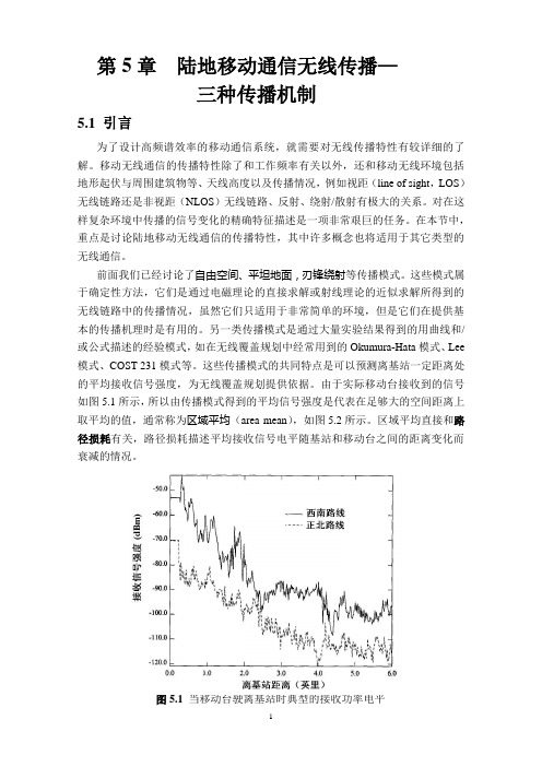
由于实际移动台接收到的信号如图5.1所示,所以由传播模式得到的平均信号强度是代表在足够大的空间距离上取平均的值,通常称为区域平均(area mean),如图5.2所示。
区域平均直接和路径损耗有关,路径损耗描述平均接收信号电平随基站和移动台之间的距离变化而衰减的情况。
图5.1当移动台驶离基站时典型的接收功率电平如果对图5.1所示的测量信号包络或其平方包络(功率),在40个波长的空间距离上取平均的话,就可以得到均值包络或均方包络。
这个量有时被称为本地均值(local mean),因为它和特定地点的平均值相对应,见图5.2。
由于诸如高层建筑物和丘陵这样的地形地物特征的出现,通常,本地均值也将会在几十个波长的距离上经历慢的随机变化。
天线与电波传播_完整版

§1.1 辅助函数法
在远场区
E jA E jA E jA Er 0
1 j ˆE ˆ A H r r
天线辐射问题分析过程
§1.2 电基本振子
什么是电基本振子? 一段通有高频电流的直导线,当导线长度远远小于
§1.2 电基本振子
近区场的性质:由于电场和磁场相差90度,故坡印 廷矢量的平均值等于零,这说明无电磁场能量辐射, 称为感应场。 远区场:当 kr 1 时称为远场区,电磁场主要由 kr 的低次幂项决定,故可略去 kr 的高次幂项,得
Er E H r H 0 jkr kI 0l e E j sin 4 r kI 0l e jkr H j sin 4 r
§1.2 电基本振子
电基本振子的场辐射
§1.3 磁基本振子
麦克斯韦电磁理论获得了巨大的成功。电和磁的 对称性问题,至今尚未解决。 电的基本单元是电荷。正负电荷可以分开,自由 电荷能单独存在,因而我们可以引进电荷密度和电 流密度的概念。 磁的基本单元是磁偶极矩,它可以看作是正负磁 荷的组合。然而,正负磁荷却不能分开,自由磁荷 不能单独存在。所以,在电磁理论中我们不能引入 磁荷密度和磁流密度等概念。
天线发展简史
五、2000, 移动/手持天线(Mobile/Hand - held Antenna) 工作于800MHz的手持蜂窝电话天线随处可见。 从马可尼时代直到20世纪40年代,天线主要是以 导线为辐射单元,工作频率也提高到UHF。 进入二战期间,随着1GHz以上微波源(如调速 管、磁控管)的发明,天线开始了一个新的纪元。 波导口径天线、喇叭天线和反射面天线等如雨后春 笋般出现。
《天线与电波传播》课件

电波在自由空间中传播时,能量随距离的平 方成正比地衰减。
穿透损耗
电波在穿透建筑物、墙体等障碍物时,会受 到损耗。
地面吸收损耗
电波在传播过程中,会受到地面的吸收作用 ,导致能量衰减。
散射损耗
由于散射体的散射作用,导致电波传播过程 中的能量衰减。
03
天线设计与应用
BIG DATA EMPOWERS TO CREATE A NEW
ERA
Hale Waihona Puke 天线的定义与分类总结词
天线的定义是指能够将电磁波能量转换为导行波能量或将导行波能量转换为电磁波能量 的装置。天线根据不同的分类标准可以分为多种类型。
详细描述
天线是一种能够将电磁波能量转换为导行波能量或将导行波能量转换为电磁波能量的装 置。根据不同的分类标准,天线可以分为多种类型,如按工作性质可以分为发射天线和 接收天线,按方向性可以分为定向天线和全向天线,按频段可以分为超长波天线、长波
BIG DATA EMPOWERS TO CREATE A NEW ERA
《天线与电波传播》ppt课
件
• 天线基础知识 • 电波传播基础 • 天线设计与应用 • 电波传播的干扰与防护 • 未来发展与展望
目录
CONTENTS
01
天线基础知识
BIG DATA EMPOWERS TO CREATE A NEW
设备干扰
影响设备的正常运行,可能导致设 备故障或性能下降。
04
干扰的防护与抑制
频率管理
通过合理规划和管理无线电频谱,减少不同无线电业务之间的干扰。
天线隔离
通过合理设置天线位置和方向,降低不同无线电设备之间的干扰。
滤波技术
采用滤波器对信号进行筛选和处理,减少干扰信号的影响。
通信技术概论第五章数字微波通信系统
5.2 微波的视距传播特性
发射天线
h1
d
d1
hc d 2
d
R 1
接收天线
h2
d’——直视距离 hc——余隙 d ——最大通信距离(最 大视距传播距离或最大 传播距离)
发射天线
接收天线
d
hc
h1
h2
d
(a)实际
(b)简化
5.2.1 视距与天线高度的关系
5.2 微波的视距传播特性
图5.2.1中,发射天线和接收天线之间的连线表示它们之 间的直视路径,其长度为直视距离(d );
波段名称 K V Q M E N D
频率范围(GHz) 18~26.5 26.5~40 33~50 50~75 60~90 90~136 137~143
5.1 数字微波通信概述
5.1.3 微波通信的概念
♣ 微波通信(microwave communication ):是一种利用 微波作为载波传送信息的通信手段,即载波频率是微波。也可 以说,凡是利用微波传播进行的通信均为微波通信。
5.1 数字微波通信概述
♣ 我国微波通信的发展 我国第一条微波中继通信(试验)电路是北京-方庄- 杨村-天津,该电路于1960年4月开通。 1976年,我国以北京为中心连通全国20多个省市建成了 大规模的微波通信干线。 20世纪80年代,随着数字信号处理技术和大规模集成 电路的发展,微波通信系统得到迅速发展。 20世纪90年代后出现了容量更大的数字微波通信系统
5.1.2 微波的概念
♣ 微波(microwave):微波是一种电磁波,是全部电 磁波频谱的一个有限频段。即波长介于1毫米到1米,或频率 介于300MHz~300GHz之间的电磁波。
【注】“微”,就是该无线电波的波长相对于周围物体的 几何尺小很小的意思。
天线知识培训
天线知识培训一、天线基本原理天线是无线通信系统中的重要组成部分,负责将电磁波传输和接收。
天线能够将电流元转换为电磁波,或者将电磁波转换为电流元。
其基本原理基于电磁波的传播和辐射。
二、天线类型与用途1. 按照工作频段:可分为超长波、长波、中波、短波、超短波以及微波等类型。
2. 按照方向性:可分为全向和定向天线。
3. 按照增益:可分为无源和有源天线。
4. 按照结构:可分为线天线和面天线。
不同类型的天线有不同的用途,例如长波天线用于通信和导航,短波天线用于电报通信和广播,超短波天线用于电视、雷达和移动通信等。
三、天线参数与性能1. 阻抗:天线的输入阻抗应与信号源的输出阻抗相匹配,以实现最佳传输效果。
2. 方向图:表示天线接收和辐射电磁波的方向和强度。
3. 增益:表示天线辐射或接收电磁波的能力,与天线的尺寸、形状和材料有关。
4. 带宽:表示天线的工作频率范围。
5. 极化:表示电场矢量的方向,影响着天线的性能。
四、天线辐射与传播天线的辐射原理是将电磁能转化为向空间发散的电磁波,或者将空间中的电磁波转化为电流元。
电磁波在传播过程中受到各种因素的影响,如空气阻力、地面反射等,形成不同的传播模式。
五、天线材料与工艺天线的材料和工艺对其性能有着重要影响。
常用的天线材料包括铜、铝、铁等金属材料,以及塑料、陶瓷等非金属材料。
工艺方面,需要考虑天线的精度、防腐、防水等因素。
六、天线设计与优化天线的设计过程需要考虑诸多因素,如阻抗匹配、增益、方向图、极化等。
现代计算机辅助设计软件的应用使得天线的优化设计成为可能,通过对天线结构、尺寸和材料等因素的调整,可以得到最佳的性能表现。
七、天线测量与调试天线的性能需要通过实际测量来评估。
测量内容包括阻抗、方向图、增益、极化等。
一旦发现性能不佳,需要进行调试,调整天线的结构、尺寸或工作参数等,以实现最佳性能。
八、天线干扰与防护天线在使用过程中可能会受到各种干扰,如其他电磁波的干扰、雷电的袭击等。
无线传播和天线
在不同环境下,分集接收的效果不同。 在非常空旷的地区,由于不存在多径衰落,或者说多径衰落很 弱,在这种情况下,采用定向双极化天线极化分集接收的效果不如 使用单极化天线的空间分集接收。 而在多径衰落严重的用户密集地区,使用定向双极化天线的极 化分集接收,效果非常显著。
1.3.3 电波的绕射传播
电波在传播途径上遇到障碍物时,总是力图绕过障碍物, 电波在传播途径上遇到障碍物时 , 总是力图绕过障碍物 , 再向前传播。这种现象叫做电波的绕射。超短波的绕射能力较弱, 再向前传播。这种现象叫做电波的绕射。超短波的绕射能力较弱, 在高大建筑物后面会形成所谓的“阴影区”。信号质量受到影响 在高大建筑物后面会形成所谓的“阴影区” 的程度不仅和接收天线距建筑物的距离及建筑物的高度有关, 的程度不仅和接收天线距建筑物的距离及建筑物的高度有关,还 和频率有关。 和频率有关。例如一个建筑物的高度为10米,在距建筑物200米处接收的信号质量几
用分集接收改善信号电平
由于电磁波在传播的过程中,会遇到多径衰落的问题,为了减 小多径衰落的影响,提出了各种抗衰落的通讯模式,分集接收就是 其中的一种。 分集接收的信号合并技术: 1、选择性合并; 2、等增益合并; 3、最大比合并; 在设计系统时,根据其应用领域,采用的信号合并技术也不相 同。常用分集接收有空间分集和极化分集两种。 根据统计结果分析,空间分集和极化分集,都能达到改善通讯 效果的目的。 空间分集常使用单极化天线。 极化分集常使用双极化天线。
o
x
z
无线电波有点象一个池塘上的波纹,在传播时波会减弱。 无线电波有点象一个池塘上的波纹,在传播时波会减弱。 有点象一个池塘上的波纹 无线电波和光波一样,它的传播速度和传播媒质有关。 无线电波和光波一样,它的传播速度和传播媒质有关。 无 线电波在真空中的传播速度等于光速。我们用C= C=30000 线电波在真空中的传播速度等于光速。我们用C=30000 公里/秒表示。在媒质中的传播速度为:Vε`=C/√ε, :Vε`=C/√ε 0公里/秒表示。在媒质中的传播速度为:Vε`=C/√ε, 式中ε为传播媒质的相对介电常数。 式中ε为传播媒质的相对介电常数。空气的相对介电常数与真 空的相对介电常数很接近,略大于1。 空的相对介电常数很接近,略大于1
电子课件-《无线电基础(第五版)》-A05-3646 课题一 无线电通信荔统和信号传输

课题一 无线电通信系统和信号传输
1.传输线的种类 (1) 平行双线 平行双线是一种对称式或平衡式的传输线,它由两根线径 相等的平行导线组成。 (2) 同轴电缆 如图所示,同轴电缆由同轴排列的内外两个导体组成,内 导体是实心导线,外导体是金属编织网(起屏蔽作用,使用时 需要接地) ,内外导体间充以高频绝缘介质,表面附有塑料保 护层。
课题一 无线电通信系统和信号传输
天线的反射损耗示意图
课题一 无线电通信系统和信号传输
3. 天线的架设 天线的实际架设如图所示。
天线的实际架设图课题一来自无线电通信系统和信号传输本任务的内容是认识天线和传输线并测试无线电
任务描述 信号的场强。
常见的天线实物图 a) 磁性天线 b) 拉杆天线 c) 蝙蝠翼天线 d)引向天线 e)板状天线 f)抛物面天线
课题一 无线电通信系统和信号传输
相关知识 一、天线
天线是辐射和接收无线电波的装置。天线实质上是 一个能量转换器,发射天线是把高频电流形式的能量 转换为无线电波形式的能量,并将无线电波辐射到空 间的装置;反过来,接收天线是把无线电波形式的能 量转换为高频电流形式能量的装置。
课题一 无线电通信系统和信号传输
(4) 按照结构形式分类 天线可分为线天线和面天线两种。 (5) 按照方向性分类 天线可分为全向天线和定向天线。
课题一 无线电通信系统和信号传输
2 . 天线的参数 (1)输入阻抗 天线输入端信号电压与信号电流之比,称为天线的输入阻 抗。 (2) 效率 天线效率是用来衡量天线将高频电流转换为无线电波能量 的有效程度。 (3) 方向图 天线具有方向特性。
课题一 无线电通信系统和信号传输
第5章无线传输试题答案
第5章无线传输技术一、填空题1.微波中继通信是利用__微波___作为载波并采用中继方式在地面上进行的无线电通信。
2.微波中继传输系统中包含各类微波站,其中有终端站、中继站、__分路站_______和____枢纽站_____。
3.微波通信中,在一条微波线路只有一个波道的情况下,其频率分配大多采用__二频制_______方案。
4. 卫星通信是微波通信中的一种特殊形式,它是利用__卫星_______作为中继来转发微波信号。
5.根据信号与信道变化快慢程度,衰落分为快衰落和__慢衰落_______。
二、单项选择题:1.超短波通信只能靠直线方式传输,传输距离约(A)km。
A.50B.100C.150D.2002.长波通信(包括长波以上)主要由( B)传播,也可在地面与高空电离层之间形成的波导中传播,通信距离可达数千公里甚至上万公里。
A.天波B.地波C.空间波D.流星余迹3.短波通信也称高频通信,主要靠(A)传播,可经电离层一次或数次反射,最远可传至上万公里。
A.天波B.地波C.空间波D.流星余迹4.( C)即直达波,沿视距传播。
A.地波B.天波C.空间波D.大气层波5.超短波通信的特点是( A )。
A.工作频带宽B.天线尺寸大C.传输距离远D.主要靠天波传播6.无线通信中的码分多址是一种利用(A)所形成的不同码序列实现的多址方式。
A.扩频技术B.调制技术C.编码技术D.均衡技术7.频分多址是按照( B )的不同给每个用户分配单独的物理信道,这些信道根据用户的需求进行分配,在用户通话期间,其它用户不能使用该物理信道。
A.时间B.频率C.空间D.码序列8.以传输信号空间位置的不同来划分并建立多址接入的方式称为( C)。
A.FDMAB.TDMAC.SDMAD.CDMA9.将接收到的各支路信号进行相同的加权后,再进行合并的分集合并技术是(A)。
A.等增益合并B.开关式合并C.最大比合并D.选择式合并10.(D)利用数字信号处理技术,产生空间定向波束,使天线主波束对准用户信号到达方向,旁瓣或零陷对准干扰信号到达方向。
无线通信基础知识

第一章 无线通信的基本概念
1.3 联通GSM900M数字蜂窝网移动通信系统:
工作频段:上行909~915MHz 下行954~960 MHz
频率与信道之间换算公式:上行:F=890+0.2*指令载波频率号
下行:F=935+0.2*指令载波频率号
联通GSM900M系统使用频点为96-124.
第一章 无线通信的基本概念
第一章 无线通信的基本概念
1.2 移动GSM1800M数字蜂窝网移动通信系统:
工作频段:上行1710-1720MHz
下行1805-1815MHz
频率与信道之间换算公式:上行:1710.2MHz+(N-512)*0.2
下行:1805.2MHz+(N-512)*0.2
移动GSM1800M系统使用频点为512-561.
频段名称 极低频(ELF) 超低频(SLF) 特低频(ULF) 甚低频(VLF) 低频(LF) 中频(MF) 高频(HF) 甚高频(VHF) 频率范围 3~30Hz 30~300Hz 300~3000Hz 3~30kHz 30~300kHz 300~3000kHz 3~30MHz 30~300MHz 波段名称 极长波 超长波 特长波 甚长波 长波 中波 短波 超短波 (米波) 波长范围 100~10Mm(108~107m) 10~1Mm(107~106m) 1000~100km(106~105m) 100~10km(105~104m) 10~1km(104~103m) 1000~100m(103~102m) 100~10m(102~10m) 10~1m
自由空间损耗公式:Ls=32.45+20lgF+20lgD
思考题
• 何谓无线通信? • WCDMA的工作频段?该频段属于哪一波段 ? • 按照自由空间损耗公式计算参考距离为1m处
天线与电波传播课件

兔耳朵偶极子天 线用于电视接收
绕杆式天线用于 商业电台的发射
抛物面天线用于 天空通信
移动通信基站天线
桅杆天线
折合偶极子天线
八木天线用于业 余电台
八木天线用于军 用移动通信
喇叭天线
螺旋天线
手机外置天线
内置天线在手机 中的位置
手机天线
手机天线
RFID天线
RFID天线
RFID tag 天线
BT 天线
兔耳朵偶极子天线用于电视接收绕杆式天线用于商业电台的发射抛物面天线用于天空通信移动通信基站天线桅杆天线折合偶极子天线八木天线用于业余电台八木天线用于军用移动通信喇叭天线螺旋天线手机外置天线内置天线在手机中的位置手机天线手机天线rfid天线rfid天线rfidtag天线bt天线分形天线meanderline天线天线与无线通信系统的关系scenarios软件无线电sdr认知无线电cognitiveradio天线研究的理论体系和方法foundation解析方法analytic数值方法numeric天线设计的方法论methodology分析analysis综合synthesis天线设计实例1多频段手机天线设计应用
天线结构
设计过程
天线设计实例(2)-UWB天线设计
应用:FCC UWB频段(3.1GHz~10.6GHz) IEEE802.16a(2GHz~11GHz) IEEE802.16e (2GHz~6GMHz) 结构:小型化,简洁,低成本 性能:反射系数; 电流分布; 方形图
-解析方法(analytic), 数值方法(numeric)
பைடு நூலகம்
天线设计的方法论(methodology)
-分析(analysis), 综合(synthesis)
5天线基本知识与应用-第五讲 链路及空间无线传播损耗计算
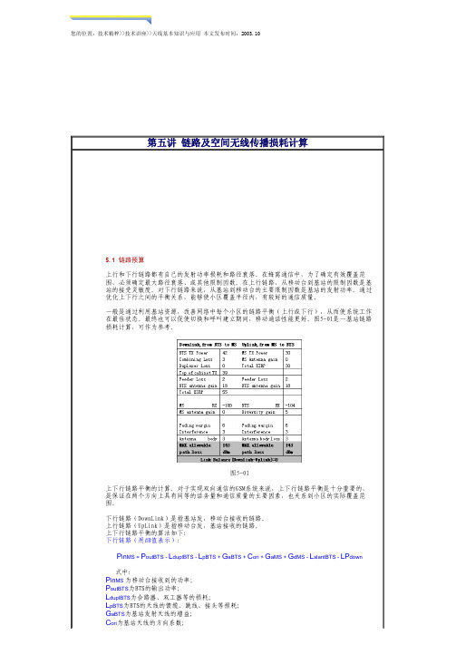
您的位置:技术精粹>>技术讲座>>天线基本知识与应用 本文发布时间:2003.10第五讲 链路及空间无线传播损耗计算5.1 链路预算上行和下行链路都有自己的发射功率损耗和路径衰落。
在蜂窝通信中,为了确定有效覆盖范围,必须确定最大路径衰落、或其他限制因数。
在上行链路,从移动台到基站的限制因数是基站的接受灵敏度。
对下行链路来说,从基站到移动台的主要限制因数是基站的发射功率。
通过优化上下行之间的平衡关系,能够使小区覆盖半径内,有较好的通信质量。
一般是通过利用基站资源,改善网络中每个小区的链路平衡(上行或下行),从而使系统工作在最佳状态。
最终也可以促使切换和呼叫建立期间,移动通话性能更好。
图5-01是一基站链路损耗计算,可作为参考。
图5-01上下行链路平衡的计算。
对于实现双向通信的GSM系统来说,上下行链路平衡是十分重要的,是保证在两个方向上具有同等的话务量和通信质量的主要因素,也关系到小区的实际覆盖范围。
下行链路(DownLink)是指基站发,移动台接收的链路。
上行链路(UpLink)是指移动台发,基站接收的链路。
上下行链路平衡的算法如下:下行链路(用dB值表示):P in MS = P outBTS - L duplBTS - L pBTS + G aBTS + C ori + G aMS + G dMS - L slantBTS - LP down 式中:P in MS 为移动台接收到的功率;P outBTS为BTS的输出功率;L duplBTS为合路器、双工器等的损耗;L pBTS为BTS的天线的馈缆、跳线、接头等损耗;G aBTS为基站发射天线的增益;C ori为基站天线的方向系数;G aMS为移动台接收天线的增益;G dMS为移动台接收天线的分集增益;L slantBTS为双极化天线的极化损耗;LP down为下行路径损耗;上行链路(用dB值表示):P inBTS = P outMS - L duplBTS - L pBTS + G aBTS + C ori + G aMS + G dBTS -LP up +[G ta]式中:P inBTS为基站接收到的功率;P outMS为移动台的输出功率;L duplBTS为合路器、双工器等的损耗;L pBTS为BTS的天线的馈缆、跳线、接头等损耗;G aBTS为基站接收天线的增益;C ori 为基站天线的方向系数;G aMS为移动台发射天线的增益;G dBTS为基站接收天线的分集增益;G ta为使用塔放的情况下,由此带来的增益;LP up为上行路径损耗。
- 1、下载文档前请自行甄别文档内容的完整性,平台不提供额外的编辑、内容补充、找答案等附加服务。
- 2、"仅部分预览"的文档,不可在线预览部分如存在完整性等问题,可反馈申请退款(可完整预览的文档不适用该条件!)。
- 3、如文档侵犯您的权益,请联系客服反馈,我们会尽快为您处理(人工客服工作时间:9:00-18:30)。
Velocity of electromagnetic wave is a function of the density of the medium
When wave changes medium, speed changes Wave bends at the boundary between mediums
Attenuation
Strength of signal falls off with distance over transmission medium
Attenuation factors for unguided media:
Received signal must have sufficient strength so that circuitry in the receiver can interpret the signal
Propagation Modes
Ground-wave propagation Sky-wave propagation Line-of-sight propagation
Ground Wave Propagation
Ground Wave Propagation
Follows contour of the earth Can Propagate considerable distances Frequencies up to 2 MHz Example
Free Space Loss
Free space loss equation can be recast:
LdB 1l0oP P grt 2l0og 4 d
2 l o 0 2 l g d o 0 2 . 9 g d 1 8 B
2l0 o 4 fg d 2l0 o f g 2l0 o d g 1.5 4 d 6 7 B c
Categories of Noise
Thermal Noise Intermodulation noise Crosstalk Impulse Noise
Thermal Noise
Thermal noise due to agitation of electrons Present in all electronic devices and
Free Space Loss
Free space loss, ideal isotropic antenna
P Prt 4d22 4cf2d2
Pt = signal power at transmitting antenna Pr = signal power at receiving antenna = carrier wavelength d = propagation distance between antennas c = speed of light (»3 ´ 10 8 m/s) where d and are in the same units (e.g., meters)
In two-way communication, the same antenna can be used for transmission and reception
Radiation Patterns
Radiation pattern
Graphical representation of radiation properties of an antenna
Introduction
An antenna is an electrical conductor or system of conductors
Transmission - radiates electromagnetic energy into space
Reception - collects electromagnetic energy from space
Thermal Noise
Noise is assumed to be independent of frequency Thermal noise present in a bandwidth of B Hertz
(in watts):
NkTB
or, in decibel-watts
N 1 lk o 0 1 l g T o 0 1 l g o B 0g 2 . 6 d 2 B 1 8 lT o 0 W 1 l g B o 0
Free Space Loss
Free space loss accounting for gain of other antennas can be recast as
L d 2 B l o 0 2 l g d o 0 1 lg A o t A 0 r g
2 l f o 0 2 l d g o 0 1 l A g t o A r 0 1 . 5 g d 6
transmission media Cannot be eliminated Function of temperature Particularly significant for satellite
communication
Thermal Noise
Amount of thermal noise to be found in a bandwidth of 1Hz in any device or conductor is:
N 0kTW/Hz
N0 = noise power density in watts per 1 Hz of bandwidth
k = Boltzmann's constant = 1.3803 ´ 10-23 J/K T = temperature, in kelvins (absolute temperature)
Types of Antennas
Isotropic antenna (idealized)
Radiates power equally in all directions
Dipole antennas
Half-wave dipole antenna (or Hertz antenna) Quarter-wave vertical antenna (or Marconi
rule of thumb K = 4/3
Line-of-Sight Equations
Maximum distance between two antennas for LOS propagation:
3 .5 7 h 1 h 2
h1 = height of antenna one h2 = height of antenna two
Effective area
Related to physical size and shape of antenna
Antenna Gain
Relationship between antenna gain and effective area
G4A 2e 4cf22Ae
G = antenna gain Ae = effective area f = carrier frequency c = speed of light (»3 ´ 108 m/s) = carrier wavelength
Depicted as two-dimensional cross section
Beam width (or half-power beam width)
Measure of directivity of antenna
Reception pattern
Receiving antenna’s equivalent to radiation pattern
Satellite communication – signal above 30 MHz not reflected by ionosphere
Ground communication – antennas within effective line of site due to refraction
Reflection effect caused by refraction Examples
Amateur radio CB radio
Line-of-Sight Propagation
Line-of-Sight Propagation
Transmitting and receiving antennas must be within line of sight
Free Space Loss
Free space loss accounting for gain of other antennas
P P r t 4 G rG 2t d2 2A r d A t2fc 2A rd A 2t
Gt = gain of transmitting antenna Gr = gain of receiving antenna At = effective area of transmitting antenna Ar = effective area of receiving antenna
Noise Terminology
Intermodulation noise – occurs if signals with different frequencies share the same medium
Line-of-Sight Equations
Optical line of sight
d3.57h
Effective, or radio, line of sight
d3.57h
d = distance between antenna and horizon (km) h = antenna height (m) K = adjustment factor to account for refraction,
