西门子SITRANS FUS SONOFLO启动手册2
西门子操作手册

目录1 安全信息 (1)术语定义 (1)前言 (1)2定位器的供货范围 (2)3组装…………………………………………………………………概述…………………………………………………………………定位器在潮湿环境中的使用……………………………………定位器在易受到强加速作用力或震动场合的使用……………直行程执行机构的连接附件………………………………………组装顺序……………………………………………………………角行程执行机构的连接附件………………………………………组装顺序………………………………………………………………4可选附件的安装……………………………………………………5电气连接……………………………………………………………6气动连接……………………………………………………………注入仪表空气开关………………………………………………..限流器………………………………………………………………7调试(见散页“操作—简要说明”)………………………………直行程执行机构调试准备…………………………………………直行程执行机构的自动初始化…………………………………直行程执行机构的手动初始化…………………………………角行程执行机构调试准备…………………………………………角行程执行机构的自动初始化…………………………………角行程执行机构的手动初始化…………………………………故障校正……………………………………阀门定位器的简明操作指南………………..附录一………………………………………………………………………附录二………………………………………………………………………1 安全信息1.2 前言本操作说明描述了定位器组装、连接、调试的基本步骤,不能取代SIPART PS2电气阀门定位器的操作手册,操作手册中包含了组装、功能、操作的详细信息。
无危险使用关于安全方面,定位器出厂时已达到完美状态,如果要保持此状态,用户必须要遵守本操作说明中安全提示。
操作手册(西门子系列)

页眉内容西门子802D数控铣床第一章数控系统面板显示屏右侧和下方的灰色方块为菜单软键,按下软键,可以进入软键左侧或上方对应的菜单。
有些菜单下有多级子菜单,当进入子菜单后,可以通过点击“返回”软键,返回上一级菜单。
精心整理第二章手动操作2.1返回参考点1.进入系统后,显示屏上方显示文字:0030:急停。
点击急停键,使急停键抬起。
这时该行文字消失;2.按下机床控制面板上的点动键,再按下参考点键,这时显示屏上按下机床控制面板上的点动键;先按下快进按键,然后再按坐标轴按键,则该轴将产生快速运动。
1.点击“设置”下方的软键;2.显示如下窗口,可以在这里设定JOG进给率、增量值等;精心整理3.使用光标键移动光标,将光标定位到需要输入数据的位置。
光标所在区域为白色高光显示。
如果刀具清单多于一页,可以使用翻页键进行翻页;4.点击数控系统面板上的数字键,输入数值;,系统进入精心整理第三章程序编辑3.1进入程序管理方式1.点击程序管理操作区域键;按下;2.点击编辑下方的软键;3.打开当前程序;精心整理4.使用面板上的光标键和功能键来进行编辑;5.删除:使用光标键,将光标落在需要删除的字符前,按删除键删除错误的内容。
或者将光标落在需要删除的字符后,按退格删除键进行删除。
点击数控系统面板上的数字键,输入数值;精心整理刀具的刀具号;例如,要建立刀具号为6的铣刀,其操作步骤如下:,显示屏如下显示:使用光标键移动光标,将光标定位到需要输入数据的位置。
光标精心整理第五章自动运行操作5.1进入自动运行方式1.按下系统控制面板上的自动方式键,系统进入自动运行方式:2.显示屏上显示自动方式窗口,显示位置、主轴值、刀具值以及当前的程序段。
5.2软键点击自动方式窗口下方菜单栏上的“程序控制”软键;;,就能恢复被停止的程序。
●中断:按复位键,可以中断程序加工,再按按数控启动键,程序将从头开始执行。
精心整理。
西门子电磁流量计 SITRANSF 操作说明说明书

西门子电磁流量计SITRANSF操作说明今天我们给大家带来的是西门子电磁流量计SITRANSF的操作说明书下载,希望能对大家的选型及其售后安装调试有所帮助。
一、西门子电磁流量计SITRANSF系统组件SITRANSFMMAG5000/6000流量计系统包括:●变送器(SITRANSFMMAG5000/6000类型)●传感器(型号:SITRANSFMAG1100/1100F/3100/3100P/5100W)●通信模块(可选)(类型:HART、PROFIBUSPA/DP、MODBUSRTURS485、FoundationFieldbusH1、Devicenet)●SENSORPROM存储器西门子电磁流量计SITRANSFEX要求要求如下:●电气连接符合ElexV(爆炸性危险区中的VO)和EN60079-14(在爆炸性危险区中安装电气系统)。
●正确安装电源保护盖。
对于本质安全电路,可以开盖操作。
●为输出电路使用合适的电缆连接器:本质安全:蓝色,非本质安全:黑色●传感器和变送器连接到等电位线。
对于本质安全输出电路,整个连接路径都必须保持等电位。
●传感器绝缘层的最大厚度为100mm(仅限绝缘传感器)。
●在具有可燃粉尘的区域中安装时,应考虑EN50281-1-2。
●连接保护接地(PE)时,保护接地(PE)和等电位线(PA)间不能存在电位差,即使发生故障期间也是如此。
西门子电磁流量计SITRANSF操作说明书下载西门子电磁流量计SITRANSF应用脉冲式直流励磁电磁流量计适用于测量几乎所有导电液体和固体浓度最大40%的浆体和悬浮液。
西门子电磁流量计SITRANSF主要应用于以下领域:●水和污水处理●化工和制药行业●食品与饮料行业●采矿和水泥行业●制浆和造纸行业●钢铁工业●发电、公共事业和冷却水行业西门子电磁流量计SITRANSF通信解决方案SITRANSFUSMII系列附加模块目前包括HART、FoundationFieldbusH1、MODBUSRTURS485、PROFIBUSPA/DP和Devicenet,它们均可与SITRANSFMMAG6000变送器一起应用变送器以微处理器为基础,内置多语言字母数字显示器。
西门子变频器使用手册(SIEMENSfrequencyconvertermanual)

西门子变频器使用手册(SIEMENS frequency converter manual)3.2 debugging method3.2 debugging methodIMICROMASTER 420 inverter in standard supply mode, fashion has status display board (SDP) (refer to figure 3-2), forFor multiple users, the inverter can be successfully put into operation with the default settings of the SDP and the manufacturer. If the factoryThe default setting value is not suitable for your device. You can use the basic operating board (BOP) (see Figure 3-2) or the advanced operating panel(AOP) (see Figure 3-2) modify the parameters to match them. BOP and AOP are available as options. You can tooUse the PC IBN tool "Drive Monitor" or "STARTER" to adjust the factory settings. The associated software is in tune with frequency conversionSupplied in CD ROM can be found.Status display board, basic operating board, advanced operation boardFigure 3-2 operation panel for MICROMASTER 420 inverterFor the steps to change / replace the operation panel, see therelevant appendices in this manual.PromptThe default power frequency setting value (factory setting value) can be changed using the DIP switch under SDP; the setting of the converter deliveryAs follows:DIP switch 2:Off position?:Default values for Europe(50 Hz, power unit: kW)On position?:Default values for North America(60 Hz, power unit: HP)DIP switch 1:Not for user use.3.2.1 is debugged and operated using the status display panel (SDP)3.2.1 is debugged and operated using the status display panel (SDP)The SDP on the panel has two LED for displaying the current running state of the inverter (see Section 6.1).When SDP is adopted, the preset value of the converter must be compatible with the following motor data:Motor rated powerMotor voltageMotor rated currentMotor rated frequency(it is recommended to use SIEMENS Standard Motors)In addition, the following conditions must be satisfied:Linear V/f motor speed control, analog potentiometer input.50 Hz power supply, the maximum speed is 3000 rpm (60 Hz, the power supply is 3600 RPM)The analog input potentiometer is controlled.Ramp up time / slope descent time = 10 sWhen the application conditions are more complex, the settingvalue of the frequency converter can be debugged with BOP or AOP in the parameter table and section 3.2.2Found in a brief explanation.Table 3-1 default settings for operations with SDPDefault operation for terminal parametersNumeric input 15 P0701 = '1' ON, forward runningThe digital input 26 P0702 = '12' runs backwardDigital input 37 P0703 = '9' fault resetOutput relay 10/11 P0731 = '52.3' fault identificationAnalog output 12/13 P0771 = 21 output frequencyAnalog input 3/4 P0700 = 0 frequency setting1/2 analog input powerBasic operations performed with SDPBasic operations performed with SDPUsing the SDP installed on the inverter, you can do the following:Start and stop motorsThe reverse of the motorReset?A brief description of 3.2.2 debugging with BOP or AOPA brief description of 3.2.2 debugging with BOP or AOPPrerequisite:Mechanical and electrical installations have been completed.PromptWe recommend that you follow the above diagram for debugging.Set the frequency of the motorDIP switch 2:Off = 50 Hz / ON = 60 HzQuick debug P0010 = 1See section 3.2.3Debugging through P0004 and P0003A brief description of the parameter structure is given in section 5.3,For parameter details, see the parameter list".3.2.2.1 debug with the basic operating board (BOP)With the basic panel (BOP), each parameter of the frequency converter can be changed. To make use of BOPTo set parameters, you must first remove the SDP and load the BOP (see Appendix).BOP has 7 segment display of five digit number, can display parameter serial number and numerical value, alarm andFault information, as well as set and actual values. The parameter information cannot be stored in BOP.Table 3-2 represented by the BOP operation of the factory default settings.PromptBy default, the use of BOP to control the function of the motor is prohibited. If you want to control with BOP, parametersP0700 should be set to 1, and parameter P1000 should also be set to 1.When the frequency converter is added to the power supply, the BOP can also be loaded into the frequency converter, or the BOP can be removed from the converter.If the BOP has been set to I/O control (P0700=1), the drive device will stop automatically when the BOP is removedCar.Table 3-2 default settings for operations with BOPParameter description defaults to Europe (or North America) regionsP0100 mode of operation, Europe / North America, 50 Hz, kW (60Hz, HP)P0307 power (motor rating) kW (Hp)The rated frequency of the P0310 motor is 50 Hz (60 Hz)The rated speed of the P0311 motor is 1395 (1680) RPM [depending on the variable]P1082 maximum motor frequency 50 Hz (60 Hz)The basic operation panel (BOP) on the buttonDescription of display / button functionStatus display LCD shows the current setting value of the inverter.Start frequency converter, press this button to start frequencyconverter. When the default value is running, the key is blocked. For this key operation to be valid, P0700 = 1 should be set.Stop the frequency converter OFF1: press this button, the inverter will slow down at the selected ramp down rate. The key is blocked when the default value is running. In order to allow this key operation, P0700 = 1 should be set. OFF2: press this key two times (or once, but for a long time). The motor will stop freely under the action of inertia. This function is always enabled.Change the direction of the motor rotation, press this button, you can change the direction of rotation of the motor. Motor reverse sign (-) or by blinking decimal points. When the default value is running, the key is blocked, and P0700 = 1 should be set so that the operation of this key is valid.If the motor is moved, without the output of the converter, press this button to start the motor and run at the preset frequency. When this key is released, the converter stops. If the inverter / motor is running, press this button will not work.debuggingMICROMASTER 4203-8 operation manualDescription of display / button functionfunctionThis key is used for browsing auxiliary information.During the operation of the frequency converter, press any key to display any of the parameters, and hold it for 2 secondsDisplays the following parameter values (in the converter operation, starting with any one parameter):1. DC loop voltage (expressed in D - units: V),2. output current (A)3. output frequency (Hz)4. output voltage (expressed in o - units: V).5 value selected by P0005 (if P0005 chooses to display any of the above parameters (3),4 or 5) will not appear here.Press this key repeatedly, and will display the above parameters in turn.Jump functionWhen you display any parameter (rXXXX or PXXXX), press this button for a short time and jump to it immediatelyR0000, if you need, you can then modify other parameters. After you jump to r0000, press hereThe key will return to the original display point.Access parameters; press this key to access parameters.Increase the value. Press this button to increase the parameter values displayed on the panel.Reduce the value. Press this button to reduce the parameter values displayed on the panel.Figure 3-5 button on the basic panel (BOP)Change the value of the parameter with the base panel (BOP)The chart below shows how to change the value of the parameter P0004. The steps to modify the index parameter values are shown in the P0719 example listed belowFigure. According to the similar method illustrated in this chart, you can set any parameter with 'BOP'.Change the P0004 - parameter filtering functionThe result of the operation step1 press access parametersPress 2 until the P0004 is displayed3 access level by entering parameter values4 press or reach the desired value5 press to confirm and store the value of the parameter6 users can only see command parametersModify index parameter P0719Select the command / setting value sourceThe result of the operation step1 press access parametersPress 2 until the P0719 is displayed3 access level by entering parameter values4 press show current settings5 press or select the maximum frequency required to run6 press confirm and store the setting value of P0719Press 7 until the r0000 is displayed8 by return to the standard frequency converter (defined by the user)Figure 3-6 modifying parameters with BOPBusy informationWhen the value of the parameter is modified, the BOP sometimes shows:. Shows that the frequency converter is busy dealing with higher priority tasks.A number that changes the value of a parameterIn order to quickly modify the value of the parameter, each number displayed can be individually modified individually. The following steps are followed:Make sure that you are already at the access level of a parameter value (see "modify parameters with BOP").1. press the (function key), and the rightmost number blinks.2. press / modify the numeric value of this number.3. press the (function key) next to the next digit to blink.4. perform 2 to 4 steps until the desired value is displayed.5. press and exit the access level of the parameter value.PromptFunction keys can also be used to identify faults。
SITRANS F 产品系列操作指南说明书
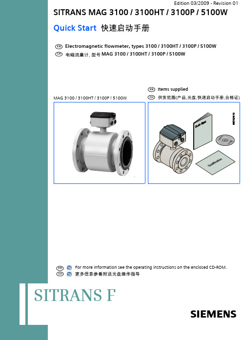
Electromagnetic flowmeter, types 3100 / 3100HT / 3100P / 5100WMAG 3100 / 3100HT / 3100P / 5100WFor more information see the operating instructions on the enclosed CD-ROM. SITRANS F2Quick Start MAG 3100 / 3100HT / 3100P / 5100WBefore installing, including in hazardous areas, refer to the operating instructions on the enclosed CD-ROM.It contains detailed safety regulations, information and specifications which must be observed when installing. Changes can occur. Documentations and approvals can be found on the Internet at /flowdocumentation.Caution!Correct, reliable operation of the product requires proper transport, storage, positioning and assembly as well as careful operation and maintenance. Only qualified personnel should install or operate this instrument.General instructionsCHFor safety reasons it is important that the following points are read and understood before the installation of the equipment:•Installation, connection, commissioning and service must be carried out by personnel qualified and authorized to do so.•It is the responsibility of the customer that the instructions and directions provided in the Quick Start and in the operating instructions on the enclosed CD-ROM are read, understood and followed by the relevant personnel before installing the equipment.•It is the responsibility of the customer to instruct and authorize personnel to operate the equipment.•It is the responsibility of the customer to ensure that the measuring system is connected correctly and is in accordance with the connection diagram.•Equipment used in hazardous areas must be Ex-approved and marked for Europe, FM for USA and CSA for Canada. It is required that the special conditions for safe use provided in the manual and in the Ex certificate are followed!•Installation of the equipment must comply with national regulations. For example EN 60079-14 for the European Community.•Repair and service must be carried out by approved Siemens Flow Instruments personnel only.Safety instructionsCHCHFlow conditionsThe pipe must be completely filled with liquid!CHMAG 3100/3100HT/3100P or MAG 5100W with Ebonite liner - Max. torqueMAG 3100/3100HT/3100P or MAG 5100W with Ebonite liner -PN40PN63PN100F/Lbs Nm F/Lbs Nm7/flowdocumentationCHStep 4Mount the connection plate in the terminal box. The SENSORPROM unit Step 5Fit the supply and output cables respectively and tighten the cable glands to CHStep 1Remove and discard the terminal box lid of the sensor. Fit the cable glands for the Step 3Connect earth wire on connection board to bottom of connection box.Connect the 2 pin connector and 3 pin connector as shown.345/flowdocumentation9Quick Start MAG 3100 / 3100HT / 3100P / 5100W 10Potting kit for IP 68 application.Quick Start MAG 3100 / 3100HT / 3100P / 5100W 12/flowdocumentation13Quick Start MAG 3100 / 3100HT / 3100P / 5100W 14SITRANS “Product name”We have reviewed the contents of this publication to ensure consistency with the hardware and software described. Since variance can-not be precluded entirely, we cannot guarantee full consistency. However, the information in this publication is reviewed regularly and any necessary corrections are included in subsequent editions. Responsibility for suitability and intended use of this instrument rests solely with the user.Copyright © Siemens AG 03.2009 All Rights Reserved. Technical data subject to change without prior notice.CHSiemens Flow Instruments A/S 6430 NORDBORGDENMARK/flowdocumentationOrder no.: A5E02451851-01Literature no.: SFIDK.PQ.027.F2.2P A5E02451851-0115Quick Start MAG 3100 / 3100HT / 3100P / 5100W。
丹佛斯流量计
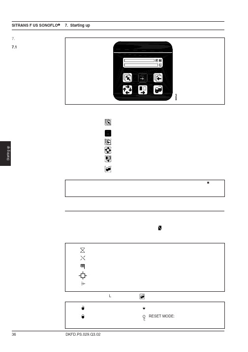
VOLUME FLOW
超声波声速
VOLUME FLOW UNIT: m3/s UNIT: m3/min UNIT: m3/h UNIT: l/s UNIT: l/min UNIT: l/h UNIT: ml/s UNIT: UGPS UNIT: UGPM UNIT: UGPH UNIT: MUGPO UNIT: Ml/d
如果信号转换器在转换过程中滞留超过10 分钟, 转换器自动地恢复到操作员菜单。 .
7.4 Sub menus
流量方向 体积流量
前一页上的总方框图给出了菜单结构的视图,下面将对总方框图中的支路方框图,即 子菜单给予更详细的说明. (请参阅支路方框图)。 .
与服务菜单有关的数据编制在“故障检修”一节中。
该菜单由两个部分组成。 即:操作员菜单和组态菜单通过按向上键2秒。
即可操作组态菜单 组态菜单有两种方式操作: 查看和组态。 查看是只读方式,组态是 读/写方式。选择的流量设置只能以查看方式阅读。组态方式的存取是由客户代码保护的, 工厂设置的代码是1000。
信号转换器始终按照流率的基本操作 菜单开始。向前页和向后页的按键用来步进操作员菜单。 .
.
设置均自动存储在信号转换器和 SENSORPROM 存储器设备中,即使电源出现故障,和信号刷新时设置仍然保持存储。 . 任何操作键的点击都可能触发灯光显示,最后一次点击操作键后,大约10分钟,灯光自动熄灭。 .
显示屏显示的数值,表示当前的流量值和流量计的设置。 三个字母F,M和L是专为以下符号保留的,请参阅键盘布置。
DKFD.PS.029.Q3.02
37
SITRANS F US SONOFLO 7. Starting up 7.3 Menu overview
2005年8月CU02sitrans指令手册说明书
Safety Guidelines: Warning notices must be observed to ensure personal safety as well as that of others, and to protect the product and the connected equipment. These warning notices are accompanied by a clarification of the level of caution to be observed.Qualified Personnel: This device/system may only be set up and operated in conjunction with this manual. Qualified personnel are only authorized to install and operate this equipment in accordance with established safety practices and standards.Unit Repair and Excluded Liability:• The user is responsible for all changes and repairs made to the device by the user or the user’s agent.• All new components are to be provided by Siemens Milltronics Process Instruments Inc.• Restrict repair to faulty components only.• Do not reuse faulty components.Warning:This product can only function properly and safely if it is correctly transported, stored, installed, set up, operated, and maintained.Note: Always use product in accordance with specifications.This document is available in bound version and in electronic version. We encourage users to purchase authorized bound manuals, or to view electronic versions as designed and authored by Siemens Milltronics Process Instruments Inc. Siemens Milltronics Process Instruments Inc. will not be responsible for the contents of partial or whole reproductions of either bound or electronic versions. While we have verified the contents of this manual for agreement with the instrumentation described, variations remain possible. Thus we cannot guarantee full agreement. The contents of this manual are regularly reviewed and corrections are included in subsequent editions. We welcome all suggestions for improvement.Technical data subject to change.MILLTRONICS®is a registered trademark of Siemens Milltronics Process Instruments Inc. Contact SMPI Technical Publications at the following address:Technical PublicationsSiemens Milltronics Process Instruments Inc.1954 Technology Drive, P.O. Box 4225Peterborough, Ontario, Canada, K9J 7B1Email: *************************• For a selection of Siemens Milltronics level measurement manuals, go to: www. /processautomation. Under Process Instrumentation, select Level Measurement and then go to the manual archive listed under the product family.• For a selection of Siemens Milltronics weighing manuals, go to:www. /processautomation. Under Weighing Technology, select Continuous Weighing Systems and then go to the manual archive listed under the product family.© Siemens Milltronics Process Instruments Inc. 2005Table of ContentsAbout the SITRANS CU 02 (1)Features (1)Specifications (2)Installation (3)Mounting (3)Rail Mounting (4)Interconnection (5)Connection Layout (5)SITRANS AS 100 Sensor Connection (5)Operation (7)Start Delay (7)Display (7)Relay (7)Analog Output (8)Setting Up (10)Operating Values (11)Programming (12)Calibration: 0 - 100% / 4 - 20 mA (12)Relays (12)Ancillary Functions (13)Parameter List (14)Security Alteration (15)Maintenance (15)About the SITRANS CU 02Note: SITRANS CU 02 is to be used only in the manner outlined in this instruction manual.The SITRANS CU 02 is an alarm control unit for use with SITRANS AS 100 acoustic sensor.Features•LCD display• 2 SPDT (form C) relays• 4 - 20 mA output, isolated•programmable start up delay•programmable alarm delaySpecificationsPower:•see nameplate for voltage configuration(100/115/200/230 V ac ±15%, 50/60 Hz, 10 VA)Environmental:•location:indoor•altitude:2000 m max•ambient temperature:-20 to 50 °C (-4 to 122 °F)•relative humidity:80% for temperatures up to 50 °C•installation category:II•pollution degree: 2Sensor Excitation:•26 Vdc nominal, 70 mA maxInput:•SITRANS Sensor 0 – 10 VdcDisplay:•liquid crystal three 9 mm (0.35") digitsmultisegment graphic for operation status Relay:• 2 alarm/control relays• 1 form ‘C’ SPDT contact per relay, rated 5 A at 250 V ac non inductiveAnalog Output:•isolated 4 - 20 mA•750 Ω load maxCable:•analog output: Belden 8760 18AWG shielded twisted pair or equivalent •latch contact input:Belden 8760 18AWG shielded twisted pair or equivalent Accuracy:•±0.02V (display) or ±40µA (mA output)Enclosure:•55 mm W x 75 mm H x 110 mm D (2.2" W x 3" H x 4.4" D)•polycarbonate•mounting:•DIN rail (DIN 46277 or DIN EN50022)•wall / panel mountIngress Protection:•IP 20Approval:•CSA general purposeWeight:•550 g (18 oz)InstallationNotes:Installation shall only be performed by qualified personnel and in accordance with local governing regulations.This product is susceptible to electrostatic shock. Follow proper groundingprocedures.MountingDimensionsWall / Panel MountingRail Mounting MountingRemovalInterconnectionConnection LayoutWARNING:•All field wiring must have insulation suitable for at least 250V.•Relay contact terminals are for use with equipment having no accessible live parts and wiring having insulation suitable for a least 250 V.•The maximum allowable working voltage between adjacent relay contacts shall be 250 V.SITRANS AS 100 Sensor ConnectionStandard Temperature VersionExtended Temperature VersionRelay Output Connection**refer to Operation \ AlarmAll relays are certified for use in equipment where the short circuit capacity of the circuits in which they are connected is limited by fuses havingratings not exceeding the rating of the relays.Analog Output ConnectionPower Connectionto customer A circuit breaker or switch in the building marked as the disconnect switch shall be in close proximity to the equipment and withineasy reach of the operator.The equipment must be protected by a 15 A fuse or circuit breaker in the buildinginstallation.Auto Reset(P14 / 24 = 0)Manual Reset(P14 / 24 = 1)reset7ML19985DN01SITRANS CU 02 – INSTRUCTION MANUAL Page 7OperationStart DelayOn initial powering of the SITRANS CU 02, the start delay circuit prevents the relays from going into alarm for the period of time programmed (parameter P80).DisplayThe SITRANS CU 02 normally displays the input signal level (Vsens) from the SITRANS sensor in volts, or in percentage of the programmed span (P3 – P2). The selection is made while viewing Vsens.Damping is provided to slow the response of the display when rapid or minor fluctuations in the process or machinery operation are encountered. The greater the damping value (P86), the slower the response.RelayThe SITRANS CU 02 has two onboard programmable relays (P10/20). Under normal operation, the relays are energized (normally open contact closed). Under alarmcondition, the `alarm' flag starts flashing immediately, indicating that the relay delay (P13/23) has started counting. If the alarm condition ceases before the relay delay expires, the flashing `alarm' flag is aborted. If the relay delay expires, the relay de-energizes and the contacts change state. The `alarm' flag ceases flashing and remains on. Uponresumption of normal operating condition, the `alarm' flag disappears. The relay and relay delay reset manually or automatically depending on the mode selected (P14/24). Ifrelay 1’alarm’ flagrelay 2’alarm’ flagprogramPage 8SITRANS CU 02 – INSTRUCTION MANUAL 7ML19985DN01automatic, the reset is immediate. If manual, the reset occurs upon actuation of the reset button (latch).Each relay is programmable for either:The individual relay functions in combination provide:•high% and high-high% alarm •high% and low% alarm •high% and bound alarm •low% and low-low% alarm •low% and bound alarm •bound 1 and bound 2 alarmAnalog OutputThe SITRANS CU 02 provides an isolated analog 4 - 20 mA output by calibration of the 4 and 20 mA levels to the operating span of the input signal (Vsens) from the SITRANS sensor. In the case where Vsens passes the lower and upper limits of the span, low and high mA limits are factory set to nominal values of 2 and 22 mA respectively, providing indication of overrange activity.Damping is provided to slow the response of the analog output when rapid or minor fluctuations in the process or machinery operation are encountered. The greater the damping value (P85), the slower the response.Note:if the SITRANS AS 100 sensor is located in areas with high RF noise, then the alarm setpoints should be set to 0.50 V above or below the fault/no fault conditions 0801000201000208010002080100high alarm:low alarm:out of bound:in bound:e.g. alarm between 20% and 80%e.g. alarm beyond 20% and 80%e.g. alarm below 20%e.g. alarm above 80%alarm condition occurs whenthe sensor signal level (%) isof a greater value than thehigh% setpointalarm condition occurs whenthe sensor signal level (%) isof a lesser value than thelow% setpointalarm condition occurs whenthe sensor signal level (%) isof a greater value than thehigh % alarm setpoint or of alesser value than the low%alarm setpointalarm condition occurs whenthe sensor signal level (%) isof a value gbetween the low%and high% alarm setpoints on off on off on off on offSecurityThe SITRANS CU 02 is factory shipped with security (P 1) disabled, allowing program access. If it is desired to deny programming access (viewing access is not restricted), security can be enabled by entering the enable code. If it is desired to regainprogramming access, the disable code must be entered. Refer to Security Alteration. Parameter ResetA master reset (P99) is provided to automatically reset all programming parameters totheir factory values. However, if it is desired to reset an individual parameter, this can be done by entering its factory value, as given in Parameter List.7ML19985DN01SITRANS CU 02 – INSTRUCTION MANUAL Page 9Setting UpTo Access Program:To Select a Parameter:To View a Parameter Value:To Change a Parameter Value:Must be pressed toSave change! To Return to Run Display Press Displayrun displayprogram startsat parameter 1to scroll upor down todesiredparameterselect parameter,e.g. P3display parametervalue, e.g. 2.50exitselect parameter,e.g. P3display parametervalue, e.g. 2.50increase or decreaseto the desired valueIf no response,security notdisabled!save and exitfrom the parameterdisplay, e.g. P3exit program andreturn to rundisplaySecurity must bedisabled!Page 10SITRANS CU 02 – INSTRUCTION MANUAL7ML19985DN01Operating ValuesWith the SITRANS Sensor and Control Unit properly mounted, connected and powered.Run the material or machinery through its range of operation.Note the following values where applicable:•normal operating level V norm = ______-•abnormal operating level V abn = ______-Where applicable values are unobtainable, they can be estimated and entered while programming.7ML19985DN01SITRANS CU 02 – INSTRUCTION MANUAL Page 11ProgrammingNote:Security must be disabled to set programming functions.Calibration: 0 - 100% / 4 - 20 mA•calibrate the 0% / 4 or 20 mA level by entering the value of V norm into P 2.•calibrate the 100% / 20 or 4 mA level by entering the value of V abn into P 3. The difference between P 2 and P 3 must be at least 0.2 V for full 4 - 20 mA span. RelaysFor precise determination of alarm setpoints, view the run display in percent and run the material or machinery through its range of operation. Note the % values corresponding to the alarm points.Note:The setpoints should be 0.50 V above or below the fault/no fault condition if thesensor is installed in high RF noise locations.Relay 1•enable, P10 = 1•setpoint:for high% alarm,P11 = enter setpoint value in %P12 = 0for low% alarm,P11 = 0P12 = enter setpoint value in %for out of bound alarm,P11 = enter high% setpoint value in %P12 = enter low% setpoint value in %for in bound alarm,P11 = enter low% setpoint value in %P12 = enter high% setpoint value in %•relay delay set (1 - 999 s), P13•reset select, P14auto = 0manual = 1Page 12SITRANS CU 02 – INSTRUCTION MANUAL7ML19985DN01Relay 2•enable, P20 = 1•setpoint:for high% alarm,P21 = enter setpoint value in %P22 = 0for low% alarm,P21 = 0P22 = enter setpoint value in %for out of bound alarm,P21 = enter high% setpoint value in %P22 = enter low% setpoint value in %for in bound alarm,P21 = enter low% setpoint value in %P22 = enter high% setpoint value in %•relay delay set (1 - 999 s), P23•reset select, P24auto = 0manual = 1Ancillary FunctionsDamping•mA output damping adjust (typical value, 1 - 50), P85•display damping adjust (typical value, 1 - 50), P867ML19985DN01SITRANS CU 02 – INSTRUCTION MANUAL Page 13Parameter ListP- 1security, reference = 500 ƒP- 20% calibration / 4 mA (V sens = 0 - 7.3 V)ƒ=0.50P- 3100% calibration / 20 mA (Vsens = 0.2 - 7.5 V)ƒ=2.50P-10relay 1, operation:0 = disabledƒ1 = enabledP-11•relay 1, high alarm setpoint (0 = disabled,1 to 100%)ƒ= 80P-12•relay 1, low alarm setpoint (0 = disabled,1 to 100%)ƒ= 20P-13•relay 1, delay (1ƒ to 999 s)P-14•relay 1, latch:0 = auto resetƒ1 = manual resetP-20 relay 2, operation:0 = disabledƒ1 = enabledP-21•relay 2, high alarm setpoint (0 = disabled, 1 to 100%)ƒ= 70P-22•relay 2, low alarm setpoint (0 = disabled, 1 to 100%)ƒ= 30P-23•relay 2, delay (1ƒ to 999 s)P-24•relay 2, latch:0 = auto resetƒ1 = manual resetP-80start delay (1 to 999 s)ƒ=10P-85damping, mA out (1ƒ to 999)P-86damping, display (1ƒ to 999)P-90software revision numberP-99reset:0 = normalƒ9 = resetƒ factory setting• accessible only if relay operation function is enabledPage 14SITRANS CU 02 – INSTRUCTION MANUAL7ML19985DN017ML19985DN01SITRANS CU 02 – INSTRUCTION MANUAL Page 15Security AlterationMaintenanceSITRANS CU 02 requires no maintenance, however a program of periodic checks is recommended.To Enable Security:To Disable Security:Press Displaysecurity enabled,programmingaccess denied enable codereference valuesecurity disabled,programmingaccess grantedsecurity disabled,programmingaccess grantedsecurity enabled,programmingaccess deniedreference valuedisable code。
西门子流量计系列在定量灌装系统中的设计选型
二、西门子流量计系列在定量灌装系统中的设计选型2.1SITRΛNSF系列流量测量仪表,SITRΛNSF系列流量测量仪表为您的应用提供最佳的技术依靠SITRANSF系列产品,西门子现在已经可以为您提供从简单的流量指示器到高端复杂的流量计,带总线接口一适合各种场合应用。
2.2电磁流量计用于测量导电液体的体积流量,也适用于含或不含悬浮颗粒物的液体,或淤泥、浆料等粘稠的介质。
任何一款电磁流量计都是由一个传感器和一个变送器组成,SITRANSFM传感器西门子提供各种传感器应用于各种工况:2.2.1SITRANSFMMAGFLOMAG5100W,MAG510OW专利的人造橡胶衬里适合所有供水及水处理行业的应用。
传感器口径DN25-DN1200(1-48)。
符合OIMLR49和ISO4064。
可与转换器MAGFLOMAG5000/MAG6000配合使用。
2.2.2SITRANSFMMAGFLOMAG3100W,MAG3100W流量传感器适用于所有供水及水处理行业的应用。
传感器口径DN25-DN1200(1-48)□可与转换器MAGFLOMAG5000/MAG6000配合使用。
2.2.3SITRANSFMMΛGFLOMAG3100,MAG3100有各种材质衬里,电极和法兰。
压力等级最高可以到350bar(5072psig)o 传感器口径DN15-DN2000(1/2to80)o有PTB,OIMLR75,OIMLR117证书。
可与转换器MAGFLOMAG5000/MAG6000配合使用。
2.2.4SITRANSFM711∕A,711∕E,711/Aand711∕E流量传感器在各种用于中都可提供杰出的性能。
对于衬里、电极、法兰材质和压力等级都有多种选项,以适合最极端的环境一包括危险区。
它显著特点是可很好的用于高压和真空,及专利的NoVolak衬里。
传感器口径DN15-DN2000(1/2-80)。
可与转换器Intermag2配合使用。
西门子SINAMICS S120 Startdrive 入门指南

4 Startdrive 组态工具 ....................................................................................................................... 37
4.1 4.1.1 4.1.2
1.7
附加信息 ..................................................................................................................... 18
1.8
OpenSSL 的使用 .......................................................................................................... 20
1.9
文档目标 ..................................................................................................................... 21
1.10
基本数据保护准则 ....................................................................................................... 22
4.3
操作界面 - 控制面板 .................................................................................................... 51
西门子SIWAREX CF装置手册说明书

SIWAREX® CF装置手册状态 2005年02月iv SIWAREX CF警告和安全术语本手册包含有为了保护您的人身安全和防止损坏装置或周围环境而应该遵守的注意事项。
这些注意事项由一个警告三角形表示,根据不同的危险程度代表下列意义:危险意思是:如果未能认真遵守相应的安全预防措施,将肯定会导致严重的财产损失、严重的人身伤害、甚至死亡。
警告意思是:如果未能认真遵守相应的安全预防措施,将能够导致严重的财产损失、严重的人身伤害、甚至死亡。
小心意思是:如果未能认真遵守相应的安全预防措施,将可能导致财产损失或轻微的伤害。
小心意思是:如果未能认真遵守相应的安全预防措施,将可能导致财产损失。
注意指的是需要加以特别关注的重要信息;这些信息涉及到产品、产品的处置或资料中的一个对应段落。
合格人员装置的安装和操作只能由合格人员执行。
在本手册的范围内,从技术安全意义出发的合格人员指的是这样一些人:他们有资格按照适用于技术安全标准,从事所有装置、系统和回路的安装、接地和标识工作。
预定用途警告本装置只能利用样本和技术描述中规定的替换件,而且只能利用由西门子公司批准或建议的外部装置和部件。
产品的安全可靠、无故障的运行不仅取决于合适的运输,还依赖于合适的贮存、组装、安装、操作和维护。
产品牌号 / 商标SIWAREX®、SIMATIC®、SIMATIC HMI®和SIMATIC NET®都是西门子AG 公司的注意商标。
任 何第三方为了他们自己的目的而使用本文件中涉及商标的其它名称都将侵犯商标所有人的权利。
版权©西门子AG 2005;版权所有,不得翻印。
未经明确许可,严禁传播或复制本资料,严禁使用和披露本 资料的内容。
违者应对相关损失承担法律责任。
保留所有权 利,包括由一种实用新型或设计的专利许可或注册所形成的 权利。
西门子(中国)有限公司上海浦东新区浦东大道1号船舶大厦7楼 电话:(021)38892381 传真:(021)38893264免责声明我们已经校验了本手册中的内容与所述硬件和软件的一致 性。
西门子超声波流量计
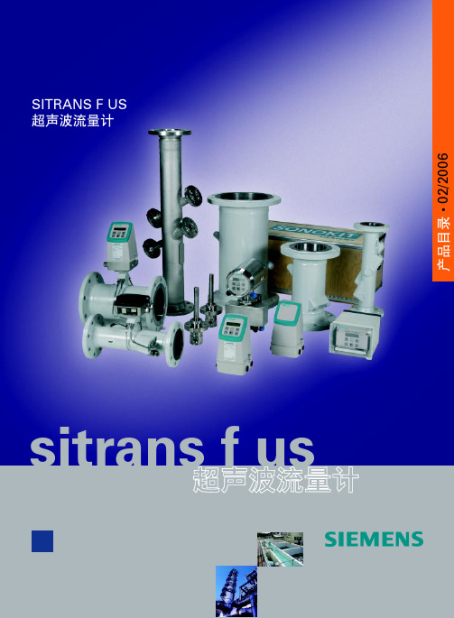
SONO SONOCAL 3000 SONOCELL 3300/3000 CT 流量计部分
SITRANS FU380
X X X X X X X X X X X X X X X X X X
X X X X X X X X X X X X X X X X X X X
A
典型的入口直管段的要求是上游 10 x Di ( D i= 流量计直径 ),下游 3 x Di 。 在满足上述安装要求的前提下,两通道超声流量计的测量精度可 达 ±0.5%
沿声道的流速分布
四通道超声流量计
在某些应用中,要求在入口管段极短的条件下或流体中存在漩涡 时获得较高精度,而两通道无法满足此需要。 对于上述情况,我们可以为您提供四通道解决方案—用户可以根 据实际入口条件向我们提出具体要求。 对于特殊应用,请联系西门子流量仪表部门。
公称尺寸和流量
6
SITRANS F US 超声波流量计
系统信息和选型指南 SONOFLO 超声波流量计
传感器选型指南
最小测量范围:0 ... 0.25 m/s 最大测量范围:0 ... 10 m/s 通常传感器选型原则为:公称流速在 3 ... 5 m/s 流速计算公式: v = (4 x Qm ax ) / (π x Di2 x 3600 ) v - m/s, Q max - m³/h, Di - m 传感器必须完全充满液体。
5
SITRANS F US 超声波流量计
系统信息和选型指南 SONOFLO 超声波流量计
■ 技术规格
m³/h 100.000 l/min. 2 l/s
50.000
D
00 N4
德国西门子伺服简明手册V2.0
第6页
为了避免编码器干扰报警,编码器电缆必须屏蔽。 屏蔽线网两端分别焊在图上的位置。
编码器接口 - 电机侧
编码器接口 - 驱动侧
为了避免编码器意外报警,在编码器插头插上时, 务必插头上的两颗螺丝用十字起紧固。
模拟量输 入/输出
50 针 MDR 连接器正面
插头背面管脚
针脚号 信号
说明
针脚号 信号
说明
1,2, 通过脉冲输入实现位置设定值。不包括 5 V 高 36,3 通过脉冲输入实现位置设定值。24 V 单端脉冲输
26,2 速差分脉冲输入(RS485),最大频率00 kHz
6
DI2
数字量输入 2
30 DO1
数字量输出 1
7
DI3
数字量输入 3
31 DO2
数字量输出 2
8
DI4
数字量输入 4
32 DO3
数字量输出 3
9
DI5
10
DI6
11
DI7
12
DI8
13
DI9
18
P12AI
19
AI1+
20
AI1-
数字量输入 5
33
数字量输入 6
34
数字量输入 7
35
数字量输入 8
49
绝对编码器负向时钟信号
4
Biss_ClockP
绝对编码器正向时钟信号
5
P5V
编码器电源,+5V
6
P5V
编码器电源,+5V
7
M
Siemens SITRANS WM100 零速报警开关说明书

Process Protection Motion sensors6■OverviewSITRANS WM100 is a heavy-duty zero-speed alarm switch.This non-contacting unit provides cost-effectiveequipment protection even in the harshest conditions.■Benefits•Up to 100 mm (4inch) gap between SITRANS WM100 andtargets•Rugged, low maintenance suitable for tough environments•1 SPDT Form C relay contact•Provides cost-effective protection•Visual indication of target triggered pulse■ApplicationThis rugged unit is impervious to dust, dirt, build-up andmoisture and is ideal for such primary industries as mining,aggregate, and cement. Operating where other systems areprone to failure, the non-contacting design eliminates the needfor lubricating, cleaning and part replacement. Downtime andclean-up expenses associated with conveying equipment failureare reduced by the SITRANS WM100. It alarms to minimizespillage, prevent extensive damage or even fire caused by beltslippage at the head pulley and warn against conveyormalfunction.The SITRANS WM100 has built-in selectable start delays and1Form C relay contact. With an aluminum body, it operates from-40to +60 °C (-40 to +140 °F).•Key Applications: tail pulleys, driven pulleys, motor shaftsensing, screw conveyor flights, bucket elevators■DesignMountingThe WM100 probe should be mounted, using the suppliedmounting flange, onto a vibration-free structure. The gap betweenthe probe and the target should be sufficient such that there is nodanger of the target damaging the probe. The maximum allowablegap is 100 mm (4inch) from the face of the target to the face of theprobe for 4.5 x 4.5 mm (3/16 x 3/16inch) keyway. The WM100 issensitive to lateral disturbances to its magnetic field. If the WM100is responding to motion from an interfering target, move the WM100or install a ferrous plate (steel) as a shield between the WM100 andthe interfering target. Where possible, the probe should bemounted such that the cable inlet is pointing downward to avoidaccumulation of condensation in the casing. Connection of theprobe should be made via flexible conduit for easier removal oradjustment of the probe.SITRANS WM100 mounting, dimensions in mm (inch)■Technical specificationsMode of operationMeasuring principle Disruption of magnetic field byferrous targetTypical application Monitors absence or presenceof motion in harsh conditionsOutputContact 1 SPDT Form C dry relay contact,rated 5 A at 250 V AC, fail-safeoperationTime delay Start up: 10... 14 seconds(5...7seconds with 12 ppmjumper installed)Zero Speed (selected via acommon jumper)•5 seconds ± 1(minimum speed 10... 15 ppm) or•10 seconds ± 2(minimum speed 5... 7.5 ppm)Rated operating conditionsOperating temperature-40... +60 °C (-40... +140 °F)DesignProbe body AluminumProcess mounting2"NPSLConnection box Aluminum, ¾" NPT conduitentrance, 5 screw terminals plusgrounding terminal for electricalconnection, max. 12 AWG(3.30 mm2) wire sizeGasketing NeopreneDisplay Red LED for verification of pulsesEnclosure rating Type NEMA 4x, 6, IP67Dynamic range Minimum 6 or 12 pulses per minuteMaximum 3000 pulses per minuteShipping weight 2 kg (4.4 lb)Power supply•115 V AC/50... 60 Hz, 7 VA•230 V AC/50... 60 Hz, 7 VA•± 10 % of rated voltageCertificates and approvals CSA US/C, CE, C-TICKProcess ProtectionMotion sensors6/276■Dimensional drawingsSITRANS WM100 mounting, dimensions in mm (inch)Selection and Ordering dataOrder No.SITRANS WM100A heavy-duty zero-speed alarm switch that does not require a controller.7MH7158 -07A 00Model 115V AC A 230V ACBSelection and Ordering dataOrder codeFurther designsPlease add "-Z" to Order No. and specify Order code(s).Manufacturer's Test Certificate: According to EN 10204-2.2C11Acrylic coated, stainless steel tag [13 x 45 mm (0.5x 1.75inch)]: Measuring-point number/identifi-cation (max. 16 characters), specify in plain text Y17Operating Instructions Order No.SITRANS WM100, English7ML1998-5MW01SITRANS WM100, GermanNote: The operating instructions should be ordered as a separate item on the order.This device is shipped with the Siemens Milltronics manual CD containing the complete operating instructions library.7ML1998-5MW31Locknut, for WM100 and Millpulse 6007MH7723-1CR Mounting flange, for WM100 and Millpulse 6007MH7723-1CS Motion cable gland adaptor kit7MH7723-1JNProcess ProtectionMotion sensors6/286■SchematicsSITRANS WM100 wiringNotes:1.Dry contacts shown in de-energized (alarm or shelf) state.2.SITRANS WM100 is manufactured for either 115 or 230 V AC operation. Check WM100 nameplate for applicable voltage. Correct voltage must be supplied. Voltages lower than specified will result in an inoperative condition. Voltages higher than specified will severely damage unit.3.For 5 second time delay and a minimum 12 ppm range, connect jumper across terminals 7 and 8. Without a jumper, the default is a 10 second time delay and a minimum 6 ppmrange.。
Sitrans CU02 控制器

使用使用说明书说明书 2005年8月SIEMENS西门子称重事业部上海浦东新区浦东大道1号船舶大厦7楼电话:(021)38892381 传真:(021)38893264 @sitrans1安全准则必须留意所有的警告事项,确保人员安全并保护产品及相关设备。
所有的警告事项都按警示程度明示出等级。
具备资质具备资质人员人员仅可按此说明书对设备/系统进行设定及操作,具备资质的人员仅在遵循已有的安全措施和标准基础上,被授权对设备进行安装和操作。
设备维修和设备维修和责任区分责任区分用户对自身或其代理商对设备的改造和维修负有责任。
所有新部件由西门子Milltronics 过程仪表提供。
仅限于故障部件的维修。
禁止重复使用故障元件。
警告警告::MSI 系列称重单元只有通过正确的运输、存储、安装、设定和维护的情况下才能够正确、安全的实现其功能。
注:确保按照相应的说明书使用本产品 西门子Milltronics 过程仪表公司 版权所有不承担的责任 该手册形式为装订本和电子文档。
我们推荐用户购买授权的装订本手册或者西门子Milltronics 过程仪表公司授权指定的电子文档。
西门子Milltronics 过程仪表不对装订本或电子文档修改的内容或所有复制版本负责。
为与仪表描述相符,在证实手册内容后,可能会有所变动。
因此,我们不保证仪表和手册完全一致。
我们会定期核查手册内容并在后续版本中进行修改。
欢迎各位提出改进的宝贵意见。
Milltronics®是西门子过程仪表的注册商标。
如有需要,请联系: 西门子称重事业部上海浦东新区浦东大道1号船舶大厦7楼 电话:(021)38892381 传真:(021)38893264 @2 目录SITRANS CU 02...........................................................................................3 优点.......................................................................................................3 规格.............................................................................................................4 安装.............................................................................................................6 装配.......................................................................................................6 导轨装配...............................................................................................7 内部连接.....................................................................................................8 布线.......................................................................................................8 连接SIRANS AS 100传感器...............................................................8 操作............................................................................................................11 启动延时..............................................................................................11 显示......................................................................................................11 继电器..................................................................................................11 模拟输出.............................................................................................13 安全保护.............................................................................................13 参数重设.............................................................................................13 启动...........................................................................................................14 操作数值.............................................................................................15 编程...........................................................................................................16 标定标定::0-100%/4-20mA .....................................................................16 继电器.................................................................................................16 辅助功能.............................................................................................17 参数列表.............................................................................................18 安全变更...................................................................................................19 维护.. (20)SITRANS CU 02SITRANS CU 02是用于SITRANS AS 100声敏传感器的报警控制单元。
西门子 SITRANS LVL200S 晶体管 (NPN PNP) - 操作说明书

Vibrating Switches SITRANS LVL200S晶体管 (NPN/PNP)操作说明书 • 11/20162*7ML19985KS31*SITRANS LVL200S - 操作说明书33837-ZH-1612053*7ML19985KS31*SITRANS LVL200S - 操作说明书33837-Z H -161205目录1关于本文献资料1.1 功能 .............................................................................................................................................................................41.2 对象 .............................................................................................................................................................................41.3 使用的标记.. (42)为了您的安全2.1 获得授权的人员.........................................................................................................................................................52.2 合规使用 .....................................................................................................................................................................52.3 谨防错误使用.............................................................................................................................................................52.4 一般安全提示.............................................................................................................................................................52.5 仪表上的安全标记 ....................................................................................................................................................52.6 欧盟一致性.................................................................................................................................................................52.7 SIL认证........................................................................................................................................................................52.8 用于防爆区域的安全提示 . (53)产品说明3.1 结构 .............................................................................................................................................................................63.2 作业方式 .....................................................................................................................................................................63.3 操作 .............................................................................................................................................................................73.4 仓储和运输.................................................................................................................................................................73.5 配件 .. (74)安装4.1 一般提示 .....................................................................................................................................................................94.2安装提示 (11)5与供电装置相连接5.1 准备接线 ...................................................................................................................................................................135.2 接线步骤 ...................................................................................................................................................................135.3 单腔式外壳的接线图 . (136)投入使用6.1 一般性说明...............................................................................................................................................................166.2 调整元件 ...................................................................................................................................................................166.3 功能表 .. (177)仪表维修和故障排除7.1 维护 ...........................................................................................................................................................................187.2 排除故障 ...................................................................................................................................................................187.3 更换电子部件...........................................................................................................................................................187.4 需要维修时的步骤 .. (198)拆卸8.1 拆卸步骤 ...................................................................................................................................................................208.2 废物清除 . (209)附件9.1 技术数据 ...................................................................................................................................................................219.2 尺寸 ...........................................................................................................................................................................279.3商标 (30)用于防爆区域的安全提示请在将仪表用于防爆应用领域时遵守专门针对防爆的安全说明。
西门子变频器说明书
本书将按照这三个步骤,通过案例介绍和相关参数的说明,逐步的介绍全部MM440的调试流程。
9 MICROMASTER 440 简明调试指南 / 操作介绍
第四章 参数复位操作
参数复位: 参数复位,将变频器的参数恢复到出厂时的参数默认值。在变频器初次调试,或者参数设置混乱 时,需要执行该操作,以便于将变频器的参数值恢复到一个确定的默认状态。
全》中“警告”的规定,或不按照其中的要求操作,就可能造成死亡,严重的人生伤害或重大 财产损失。 • 只有经过认证合格的专业人员才允许操作本设备,并且在使用设备之前要熟悉本手册中所有的 安全说明和有关安装、操作和维护的规定。正确地进行搬运装卸就位安装和操作维护,是实现 本设备安全和成功地投入运行的可靠保证。 • 注意触电的危险。即使电源已经切断,变频器的直流回路电容器上仍然带有危险电压,因此, 在电源关断5分钟以后才允许打开本设备。 • 输入电源线只允许永久性紧固连接。设备必须接地(按照 IEC 536 Class 1,NEC 和其他适用的 标准)。 • MICROMASTER440 变频器是在高压下运行。 • 电气设备运行时,设备的某些部件上不可避免的存在危险电压。 • 本设备不可作为“紧急停车机构”使用(参看 EN60204,9.2.5.4.) • 本设备可按照UL508C第42节的要求在变频器内部提供电动机过载保护功能。在缺省状态下I2t保 护功能在缺省状态下是有效的。 • 最高允许的环境温度决定于设备,请参看选型样本中的数据。 • 使用前请阅读所有的安全规则和警告,并粘贴所有的警告标志。确保警告标志置于醒目的地 方,并更换已脱落或损坏的标志。
3
西门子SITRANS Probe LU超声波物位计快速启动手册
快速启动手册• 2004.11购买相关产品联系重庆艾利顿自动化 余经理 联系电话:182********SIEMENS SITRANS Probe LU7ML 1234-78910-ABC-D 系列号:GYZ / S1034567 外壳:NEMA/TYPE 4X,6,IP67环境温度:-40 ℃~80℃ 额定电源:24V 标准,30V 最大,4-20 mA西门子妙声力过程仪表有限公司,彼得堡加拿大制造参照图:23650516Class I,Div 1,A,B,C,D 组Class II,Div 1,Groups E,F,GClass III Ui=30V,Ii=120mA,Pi=0.8W Ci=3.6nF,Li=0HART警告:可能有静电危险,不可现场摩擦或清扫购买相关产品联系重庆艾利顿自动化 余经理 联系电话:182********SITRANS Probe LU 快速启动手册本手册概述了SITRANS Probe LU 的基本特性和功能。
我们强烈建议您获取手册的详细版本,这样可使您的仪表充分发挥潜能。
完整的手册可从我们的网站上下载:/index.asp?Nr=11157. 纸版手册可从当地的西门子妙声力代表处索取。
有关手册内容的问题可以通过下列联系方式咨询: Siemens Milltronics Process Instruments Inc. 1954 Technology Drive ,邮箱4225Peterborough ,Ontario ,Canada ,K9J7B1 Email: techpubs.smpi@ 版权归西门子妙声力过程仪表有限公司所有 免责声明我们鼓励用户购买有授权的装订手册或者查看西门子妙声力过程仪表有限公司设计和授权的电子版手册。
西门子妙声力过程仪表有限公司对装订手册或电子版部分或全部内容的拷贝一律不负任何责任虽然我们对手册内容是否与仪表描述一致进行了核对,但仍可能存在变动。
西门子超声波转换器fus_sono

SOUND VELOCITY
SOUND VELOCITY MIN.
SOUND VELOCITY MAX.
声速的测量单位是 米/秒,通过输入最低和最高声速来设置测量范围。 . 如果声速超过所述的范围,便激励错误继电器动作或错误指示.
DKFD.PS.029.Q3.02
39
SITRANS F US SONOFLO 7. Starting up 方框图
PULSE UNIT
VOLUME PULSE XXXXXXXX UUUU
PULSE WIDTH XXXX UUUU
频率输出特性 characteristics
SOUND VELOCITY
PULSE UNIT: UNIT: kg UNIT: kg*10 UNIT: kg*100 UNIT: ton UNIT: lb UNIT: lb*10 UNIT: lb*100
在转换器设置菜单里, 前进键 此键为各菜单间的向前翻页键。 后退键 此键为各菜单间的向后翻页键。 改换键 此键用于改变设置或数值 选择键 此键用于选择数值的数位 锁定/开锁键 此键用于确定改变设置值或进入子菜单。
以复位方式使累加器均复位,进行调零并能使复位至工厂设置。 .
注意: 用户密码、校正因数、语言选择和自动零位均不能通过复位方式,返回到工厂设置 .
服务模态提供了把输出设置成固定值(强制输出)的模式。一旦脱离了服务模式, 原按服务模式进行设置的参数均被取消。
可以选择菜单语言。
在此菜单中能够选择操作员可访问信息。
声速范围定义是在质量流量子菜单中,选择校准质量流量,并输入声速1#和声速2#。当声 速超出音速1和音速2所规定的范围时,继电器将接通。 .
当已经选择了“故障”时,最低和最高声速均是错误信息部分。
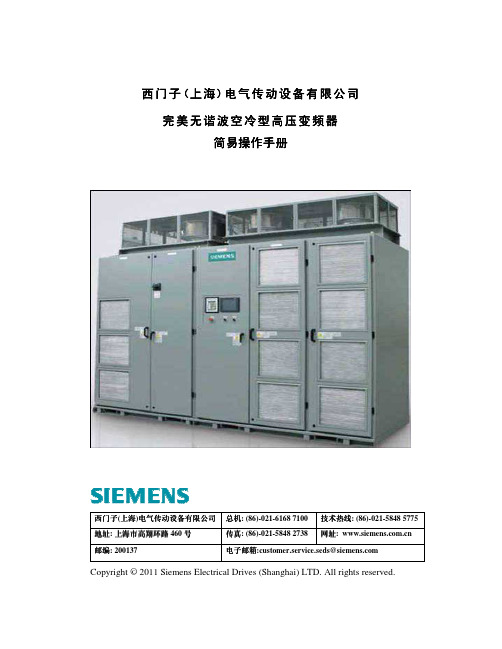
完美无谐波变频器简易操作手册
2.1 简介 ............................................................................................................................................. 10 2.1.1 变频器启动电机操作.......................................................................................................... 10 2.2.1 键盘启动变频器方法.......................................................................................................... 11 2.2.2 键盘停止变频器操作.......................................................................................................... 12
3.4.1 单元故障信息...................................................................................................................... 25 3.4.2 常见单元故障检修.............................................................................................................. 27 3.4.2 单元超温故障检修.............................................................................................................. 28 3.4.3 过压故障检修...................................................................................................................... 28 3.4.4 单元通讯和链接故障检修.................................................................................................. 29 3.4.5 高压机械旁路板状态指示灯.............................................................................................. 29 3.5 用户故障 ..................................................................................................................................... 29 3.6 意外的运行模式.......................................................................................................................... 29 3.6.1 速度回落.............................................................................................................................. 31 3.7 变频器输入保护......................................................................................................................... 32 3.7.1 单循环保护(或输入无功电流保护)................................................................................. 32 3.7.2 变频器损耗过大.................................................................................................................. 32 3.7.3 变压器超温故障.................................................................................................................. 33 3.8 故障处理流程............................................................................................................................. 33 3.9 定期维护 ..................................................................................................................................... 33 3.10 变频器运行注意事项................................................................................................................ 34
- 1、下载文档前请自行甄别文档内容的完整性,平台不提供额外的编辑、内容补充、找答案等附加服务。
- 2、"仅部分预览"的文档,不可在线预览部分如存在完整性等问题,可反馈申请退款(可完整预览的文档不适用该条件!)。
- 3、如文档侵犯您的权益,请联系客服反馈,我们会尽快为您处理(人工客服工作时间:9:00-18:30)。
购买相关产品联系重庆艾利顿自动化 余经理 联系电话:18280227007
SITRANS F US SONOFLO 7. Starting up
7.3 Menu overview
Starting up
38
DKFD.PS.029.Q3.02
购买相关产品联系重庆艾利顿自动化 余经理 联系电话:18280227007
由用户定义的 速度和密度之间 的关系
在质量流量中,选择刻度和密度测量的单位,输入二套声速和密度,质量流量测量单位 和最大质量流量范围的数据,如果设置继电器输出以指示声速范围,一旦实际声速超出 声速1和声速2给出的范围,继电器便接通,即表示密度超出规定质量流量的计算范围。 . . 选择低温,质量流量的单位和最大质量流量范围。 SONO 3000 能够测量所补偿的质量流量,即通过采用体积流量和从声速中推导出的密度计算质量 流量. 声速和密度之间的互相关系预先规定用于低温 O2 ,N2和Ar:可以输入密度和声速之间由用户定 义的相互关系,若要达到此目的,可分别输入二套声速和密度用的数据。仪表通过测量声速或密 与声速之间的插值确定其密度。 . .
基本设置
在基本设置中,能够进行流量方向、测量范围、测量单位、累加器设置和低流量切除等 选择。 . 在输出设置中,能够选择需要的输出信号。 传感器特性给出传感器信息,这种信息是从 SENSORPROM 存储器自动安装的。 远程安装时,当采用信号电缆将信号转换器接至传感器时,必须将电缆的长度输入到 应用参数中,即传感器特性的子菜单。 .
购买相关产品联系重庆艾利顿自动化 余经理 联系电话:18280227007
SITRANS F US SONOFLO 调试 7. Starting up
7.
7.1 键盘操作和 显示屏分布
键盘
键盘用于对流量计进行设定。各键功能如下: 转换键 按住此键2秒钟,可在操作菜单和设置菜单之间转换。 在转换器设置菜单里, 前进键 此键为各菜单间的向前翻页键。 后退键 此键为各菜单间的向后翻页键。
操作菜单
信号转换器始终按照流率的基本操作 菜单开始。向前页和向后页的按键用来步进操作员菜单。 . 建立菜单包栝子菜单: • • • • • • 转换器设置模式 复位模式 服务模式 语言模式 操作菜单设置 客户密码设置
设置菜单
转换器设置模式
转换器设置包栝以下3种模式: • 基本设置 • 输出模式 • 传感器特性
显示屏
显示屏显示的数值,表示当前的流量值和流量计的设置。 三个字母F,M和L是专为以下符号保留的,请参阅键盘布置。 F: 警告区:有故障出现时,有二个三角形符号频闪 M: 模式区;符号含义如下: 复位模式 服务模式 语言模式 操作采单模式 转换设置 L: 显示锁定键 的功能用下列符号: 处于改换状态 进入子菜单(按下锁定/开锁键) 锁定 数值 RESET MODE: 累加器复位设定或 使之初始化。
超声波声速
SOUND VELOCITY
SOUND VELOCITY MIN.
SOUND VELOCITY MAX.
声速的测量单位是 米/秒,通过输入最低和最高声速来设置测量范围。 . 如果声速超过所述的范围,便激励错误继电器动作或错误指示. DKFD.PS.029.Q3.02 39
Starting up
单向 Bidirectionel
双向 Unidirectionel
单向 双向
DKFD.PS.029.Q3.02
41
Starting up
购买相关产品联系重ห้องสมุดไป่ตู้艾利顿自动化 余经理 联系电话:18280227007
SITRANS F US SONOFLO 7. Starting up
用户密码设置 在此菜单中可以组态用户密码。
工厂出厂设置密码为1000,如果用户重新设置密码后,密码丢失可以采用如下方法操作。 切断电源,按住向上键,同时接通电源。当完成ROM和RAM 所以测试后,释放该键 则自动恢复到工厂设置密码1000。 如果信号转换器在转换过程中滞留超过10 分钟, 转换器自动地恢复到操作员菜单。 . 7.4 Sub menus 前一页上的总方框图给出了菜单结构的视图,下面将对总方框图中的支路方框图,即 子菜单给予更详细的说明. (请参阅支路方框图)。 . 与服务菜单有关的数据编制在“故障检修”一节中。
小流量切除 强制控制
可以在测量的范围0-- 9.9%之间设置小流量切除。 在错误的状态下,可以规定输出电流/输出频率。 通过选择“断开”输出保持在当前数值; 选择“最小”.在错误状态下,输出强迫到 0%, 选择“最大”在错误状态下,强迫输出100%。
电流输出
CURRENT OUT
CURRENT OUT OFF
DKFD.PS.029.Q3.02
37
Starting up
页面正向键 用来步进通过主菜单。 按锁定键 打开下面的子菜单。没有从子菜单返回至建立主菜单的存取, 若要离开子菜单按向上键 , 该键可 使程序返回到操作员菜单。若要在其他主菜单中进一步组态,可按向上键 2秒,然后按页面正向键, 以选择组态方式。输入用户密码, 按锁定键 并且用页面正向键 调阅主菜单页面,直到获得所需的菜单为止, 通过按锁定键存取子菜单。
低温 计算的质量流量
40
DKFD.PS.029.Q3.02
购买相关产品联系重庆艾利顿自动化 余经理 联系电话:18280227007
SITRANS F US SONOFLO 7. Starting up
累加器(内部方框图)
选择流量,方向和测量单位。 通过选择双向的流量显示净流量,即正负流量之间的差值。 。
MAX RANGE
VOL. FLOW MAX.
购买相关产品联系重庆艾利顿自动化 余经理 联系电话:18280227007
SITRANS F US SONOFLO 7. Starting up
方框图
Starting up
如果未备有SENSORPROM存储器设备的SONO 3000, 必须对显示指示格式化。 其格式如下: a) 传感器 ≤ DN 2000: 在菜单 "最大范围"中,应该输入10 x "最大质量流量." 。 b) 传感器 > DN 2000: 在菜单 "最大范围"中,应该输入5 x "最大质量流量" . (Max. 2 x 540,000 t/h).
流量方向 体积流量
流向是同时为体积流量和质量流量而定义的。
VOLUME FLOW
VOLUME FLOW UNIT: m3/s UNIT: m3/min UNIT: m3/h UNIT: l/s UNIT: l/min UNIT: l/h UNIT: ml/s UNIT: UGPS UNIT: UGPM UNIT: UGPH UNIT: MUGPO UNIT: Ml/d
PULSE UNIT: m3 UNIT: m3*10 UNIT: m3*100 UNIT: UG*0.1 UNIT: UG UNIT: UG *10 UNIT: UG*100 UNIT: MUG UNIT: L UNIT: L *10 UNIT: L*100
频率输出特性 characteristics
VOLUME FLOW MASS FLOW
SOUND VELOCITY
CURRENT OUT BIDIRECTIONAL UNIDIRECTIONAL
CURRENT OUT 4 - 20 mA 0 - 20 mA
CURRENT OUT TIME CON. XX.XS
电流输出特性 characteristics
输出设置 传感器特性
复位模式
以复位方式使累加器均复位,进行调零并能使复位至工厂设置。 . 注意: 用户密码、校正因数、语言选择和自动零位均不能通过复位方式,返回到工厂设置 .
服务模式 语言模式 操作菜单设置
服务模态提供了把输出设置成固定值(强制输出)的模式。一旦脱离了服务模式, 原按服务模式进行设置的参数均被取消。 可以选择菜单语言。 在此菜单中能够选择操作员可访问信息。
SITRANS F US SONOFLO 7. Starting up
频率/脉冲输出
FRQ./ PULSE
FRQ./PULSE OFF
VOLUME FLOW MASS FLOW
FRQ./PULSE
BIDIRECTIONAL UNIDIRECTIONAL
FRQ./PULSE
PULSE OUTPUT
PULSE UNIT
36
DKFD.PS.029.Q3.02
购买相关产品联系重庆艾利顿自动化 余经理 联系电话:18280227007
SITRANS F US SONOFLO 7.2 菜单设立结构 7. Starting up SONO3000信号转换器的菜单结构以方块图和子菜单的形式,详细的加以说明。 . 该菜单由两个部分组成。 即:操作员菜单和组态菜单通过按向上键2秒。 即可操作组态菜单 组态菜单有两种方式操作: 查看和组态。 查看是只读方式,组态是 读/写方式。选择的流量设置只能以查看方式阅读。组态方式的存取是由客户代码保护的, 工厂设置的代码是1000。
Starting up
改换键 此键用于改变设置或数值 选择键 此键用于选择数值的数位 锁定/开锁键 此键用于确定改变设置值或进入子菜单。 . 设置均自动存储在信号转换器和 SENSORPROM 存储器设备中,即使电源出现故障,和信号刷新时设置仍然保持存储。 . 任何操作键的点击都可能触发灯光显示,最后一次点击操作键后,大约10分钟,灯光自动熄灭。 .
FRQ. OUTPUT
VOLUME PULSE XXXXXXXX UUUU
PULSE WIDTH XXXX UUUU
Starting up
SOUND VELOCITY
FRQ./PULSE MAX. xxxx Hz
FRQ. OUTPUT TIME CON. xx.xs
