最新十吨位桥式起重机大车运行机构设计
10t桥式起重机小车运行机构及小车架

毕业设计(论文)报告题目 10t桥式起重机小车运行机构及小车架设计__ __院(系)_ 专业学号_____学生姓名___________指导教师__________起讫日期___ 2011.2.21-2011.6.12东南大学毕业(设计)论文独创性声明本人声明所呈交的毕业(设计)论文是我个人在导师指导下进行的研究工作及取得的研究成果。
尽我所知,除了文中特别加以标注和致谢的地方外,论文中不包含其他人已经发表或撰写过的研究成果,也不包含为获得东南大学或其它教育机构的学位或证书而使用过的材料。
与我一同工作的同志对本研究所做的任何贡献均已在论文中作了明确的说明并表示了谢意。
论文作者签名:日期:年月日东南大学毕业(设计)论文使用授权声明东南大学有权保留本人所送交毕业(设计)论文的复印件和电子文档,可以采用影印、缩印或其他复制手段保存论文。
本人电子文档的内容和纸质论文的内容相一致。
除在保密期内的保密论文外,允许论文被查阅和借阅,可以公布(包括刊登)论文的全部或部分内容。
论文的公布(包括刊登)授权东南大学教务处办理。
论文作者签名:导师签名:日期:年月日日期:年月日目录摘要 (I)Abstract (II)第一章绪论................................................................................................................... I II1.1起重机械的发展简史及发展动向.................................................................... I II1.2起重机械的应用和意义.................................................................................... I V1.3桥式起重机机构特征简介................................................................................ V I 第二章小车起升机构的设计计算 (8)2.1设计数据 (8)2.2确定起升机构传动方案,选择滑轮组和吊钩组 (8)2.3选择钢丝绳 (9)2.4确定滑轮主要尺寸 (9)2.5确定卷筒尺寸并验算强度 (9)2.6选电动机 (10)2.7验算电动机发热条件 (11)2.8选择标准减速器 (11)2.9验算起升速度和实际所需功率 (11)2.10校核减速器输出轴强度 (11)2.10.1输出轴最大径向力验算 (11)2.10.2输出轴最大扭矩验算 (12)2.11选择制动器 (12)2.12选择联轴器 (12)2.13验算起动时间 (13)2.14验算制动时间 (13)2.15高速浮动轴计算 (13)2.15.1疲劳验算 (13)2.15.2静强度计算 (14)第三章小车运行机构的设计计算 (15)3.1 确定机构传动方案 (15)3.2 选择车轮与轨道并验算其强度 (15)3.2.1疲劳计算 (15)3.2.2强度校核 (16)3.3 运行阻力计算 (16)3.4 选电动机 (16)3.5 验算电动机发热条件 (17)3.6 选择减速器 (18)3.7验算运行速度和实际所需功率 (18)3.8 验算起动条件 (18)3.9 按起动工况校核减速器功率 (19)3.10验算起动不打滑条件 (20)3.11选择制动器 (20)3.12选择联轴器 (20)3.12.1高速轴联轴器的选择 (20)3.12.2低速轴联轴器的选择 (22)3.13 验算低速浮动轴强度 (22)3.13.1疲劳验算 (22)3.13.2静强度验算 (22)第四章小车架的设计 (24)4.1 确定小车架的型式 (24)4.2 确定小车架的结构 (24)4.3 计算各构件的尺寸,决定小车架的具体构造 (26)总结 (27)致谢 (28)参考文献 (29)10t桥式起重机小车运行机构及小车架设计摘要桥式起重机在工业中占据一个至关重要的角色。
10T桥式起重机设计

目录第一章绪论 ............................................ 错误!未定义书签。
1.1 选题的意义 ........................................ 错误!未定义书签。
1.2 本课题的研究目的 (2)1.3 桥式起重机的研究现状 (2)第二章设计方案 (4)2.1 起重机的介绍 42.2 起重机设计的总体方案 42.2.1 主梁的设计 (4)2.2.2 小车的设计 (4)2.2.3端梁的设计 (5)2.2.4桥架的设计 (5)第三章大车行车机构的设计 (6)3.1 设计的原则和要求63.1.1 机构传动方案 (6)3.1.2 大车行车机构布局 (6)3.2 搭车行车机构的计算73.2.1 确定结构的传动方案 (7)3.2.2 选择车轮与轨道并校核其强度 (7)3.2.3 运行组里的计算 (9)3.2.4 选择电动机 (10)3.2.5 计算发动机的发热功率 (11)3.2.6 减速器的选择 (11)3.2.7 验算运行速度与实际功率 (11)3.2.8 验算启动时间 (12)3.2.9 校核减速器功率 (13)3.2.10 验算不打滑条件 (13)3.2.11 选择制动器 (15)3.2.12 选择联轴器 (16)3.2.13 验算浮动轴 (17)3.2.14 缓冲器的选择 (18)第四章端梁的设计 (20)4.1 端梁尺寸的确定214.2 端梁的计算214.3主要焊缝的计算24第五章端梁结头的设计 (26)5.1 端梁接头的确定和计算 265.2 主要螺栓和焊缝的设计 29第六章桥架的结构设计 (31)6.1 桥架的结构形式316.2 桥架的结构设计与计算 31第七章焊接工艺设计 (39)致谢 (42)参考文献 (43)附录 (44)第一章绪论1.1 选题意义起重机械用来对物料作起重、运输、装卸和安装等作业的机械设备,它可以完成靠人力无法完成的物料搬运工作,减轻人们的体力劳动,提高劳动生产率,在工厂、矿山、车站、港口、建筑工地、仓库、水电站等多个领域部门中得到了广泛的使用,随着生产规模的日益扩大,特别是现代化、专业化的要求,各种专门用途的起重机相继产生,在许多重要的部门中,它不仅是生产过程中的辅助机械,而且已成为生产流水作业线上不可缺少的重要机械设备,它的发展对国民经济建设起着积极的促进作用。
桥式起重机大车运行机构的计算
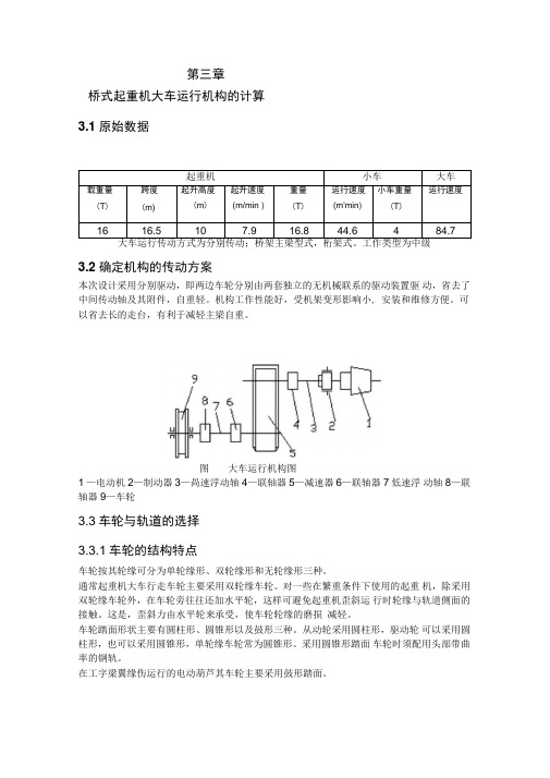
第三章桥式起重机大车运行机构的计算3.1原始数据3.2确定机构的传动方案本次设计采用分别驱动,即两边车轮分别由两套独立的无机械联系的驱动装置驱动,省去了中间传动轴及其附件,自重轻。
机构工作性能好,受机架变形影响小, 安装和维修方便。
可以省去长的走台,有利于减轻主梁自重。
图大车运行机构图1 —电动机2—制动器3—咼速浮动轴4—联轴器5—减速器6—联轴器7低速浮动轴8—联轴器9—车轮3.3车轮与轨道的选择3.3.1车轮的结构特点车轮按其轮缘可分为单轮缘形、双轮缘形和无轮缘形三种。
通常起重机大车行走车轮主要采用双轮缘车轮。
对一些在繁重条件下使用的起重机,除采用双轮缘车轮外,在车轮旁往往还加水平轮,这样可避免起重机歪斜运行时轮缘与轨道侧面的接触。
这是,歪斜力由水平轮来承受,使车轮轮缘的磨损减轻。
车轮踏面形状主要有圆柱形、圆锥形以及鼓形三种。
从动轮采用圆柱形,驱动轮可以采用圆柱形,也可以采用圆锥形,单轮缘车轮常为圆锥形。
采用圆锥形踏面车轮时须配用头部带曲率的钢轨。
在工字梁翼缘伤运行的电动葫芦其车轮主要采用鼓形踏面。
图起重机钢轨332车轮与轨道的初选选用四车轮,对面布置桥架自重:G =0.45Q 起 0.82L =20.73t =207.3kN 式中Q 起――起升载荷重量,为16000 kgL ——起重机的跨度,为16.5 m满载最大轮压:P max = U 也/ •口4 2 L式中 q ——小车自重,为4tl ――小车运行极限位置距轨道中心线距离,为1.5 m代入数据计算得:P max =132.7kN 空载最大轮压:P m :x =^q q4 2 L代入数据得P m :x =60kN 空载最小轮压:P min= G q 丄42 L代入数据得P min =43.64 kN 载荷率:Qu 」600.772G 207.3查《机械设计手册第五版起重运输件•五金件》表8-1-120,当运行速度在60 ~ 90 m min ,Q 起 ^ 0.772,工作类型为中级时,选取车轮直径为600 mm 时, 型号为P 38的轨道的许用轮压为178kN ,故可用。
10t桥式起重机总体设计(全套图纸)

摘要本次毕业设计是针对毕业实习中桥式起重机所做的具体到吨位级别的设计。
我国现在应用的各大起重机还是仿造国外落后技术制造出来的,而且已经在工厂内应用了多年,有些甚至还是七八十年代的产品,无论在质量上还是在功能上都满足不了日益增长的工业需求。
如何设计使其成本最低化,布置合理化,功能现代化是我们研究的课题。
本次设计就是对小吨位的桥式起重机进行设计,主要设计内容是10t桥式起重机的结构及运行机构,其中包括桥架结构的布置计算及校核,主梁结构的计算及校核,端梁结构的计算及校核,主端梁连接以及大车运行机构零部件的选择及校核包括: 轮压计算及强度验算, 运行阻力计算,选择电动机,减速器的选择验算,运行速度及实际功率,选择制动器,选择联轴器,低速浮动轴的验算,缓冲器的选择等计算。
还有小车的运行和起升机构零部件的选择及校核包括: 运行阻力计算,选电动机,选择减速器验算起动时间,按起动工况校核减速器功率,选择制动器,选择高速轴联轴器及制动轮,验算低速浮动轴强度,钢丝绳的选择,滑轮、卷筒的计算,联轴器的选择。
关键词: 起重机;大车运行机构;小车运行结构;小车起升结构;桥架;主端梁AbstractThe graduation design is aimed at the graduation fieldwork medium-sized crane do specific to tonnage level of design. Our country is the application of the big crane or counterfeit foreign backward technology out of manufacture and has within the plant for many years, some even application or the 70s and 80s products, both in quality and in on the function can't satisfy the growing industrial demand. How to design makes it the lowest cost, decorate rationalization, functional modernization is our topic. This design is on small tonnage design of bridge crane, the main design content is 10t bridge crane structure and operation organization, including bridge structure arrangement calculation and checking the structure of the girder, the calculation and checking, calculated and checked the beam structure, the main girders connection and cart mechanism parts selection and checking including: wheel pressure calculation and intensity checking, running friction calculation, the choice of motor, gear reducer is checked, choose speed and actual power, choose brakes, choose coupling calculating speed floating axis, buffer choice calculation, etc. And car running and lifting mechanism parts selection and checking including: running friction calculation, choose motor, choose reducer, by starting checked start-up time check reducer power, choose working brakes, choose high-speed couplings and brake wheel, the checking low-speed axial intensity, the wire rope floating choice, pulley, drum calculation, coupling choice.Keywords: cranes; During operation organization; Car running structure; Car hoisting structure; Bridge; Main girders目录摘要 (1)Abstract (2)前言 (1)第1章桥式起重机的概述 (2)1.1 桥式起重机的特点 (2)1.2 桥式起重机的用途 (4)1.3 桥式起重机的基本参数 (5)1.4 桥式起重机主要零部件 (9)1.4.1吊钩 (9)1.4.2钢丝绳 (10)1.4.3 滑轮和滑轮组 (13)1.4.4 滑轮组类型及选配原则 (14)1.5滑轮组及其滑轮组的倍率 (15)1.6 卷筒 (16)1.7 位置限位器 (16)1.8 缓冲器 (17)1.9桥式起重机发展概述 (18)1.9.1 国内桥式起重机发展动向 (18)1.9.2 国外桥式起重机的发展动向 (19)第2章大车运行机构的设计 (20)2.1大车运行结构设计的基本思路及要求 (20)2.2 大车运行机构传动方案的确定 (21)2.3 大车运行机构具体布置时要注意的问题 (21)2.4 大车运行机构的设计计算 (22)2.4.1 大车运行结构的传动方案 (22)2.5轮压计算及强度验算 (23)2.5.1计算大车的最大轮压和最小轮压 (23)2.5.2 强度计算及校核 (24)2.6 运行阻力计算 (26)2.7 选择电动机 (27)2.8 减速器的选择 (29)2.9 验算运行速度及实际功率 (29)2.10 验算启动时间 (30)2.11 起动工况下校核减速器功率 (32)2.12 验算起动不打滑条件 (32)2.13 选择制动器 (35)2.14 选择联轴器 (36)2.15 低速浮动轴的验算 (37)2.16 缓冲器的选择 (38)第3章起升小车的计算 (41)3.1 确定机构的传动方案 (41)3.2小车运行机构的计算 (42)3.3选择车轮与轨道并验算起强度 (42)3.4运行阻力计算 (44)3.5 选电动机 (46)3.6 验算电动机发热条件 (46)3.7 选择减速器 (47)3.8 验算运行速度和实际所需功率 (47)3.9验算起动时间 (48)3.10 按起动工况校核减速器功率 (49)3.11 验算起动不打滑条件 (50)3.12 选择制动器 (51)3.13 选择高速轴联轴器及制动轮 (51)3.14 验算低速浮动轴强度 (53)3.15 起升机构的设计参数 (54)3.16 钢丝绳的选择 (55)3.17 滑轮、卷筒的计算 (56)3.18 根据静功率初选电动机 (58)3.19 减速器的选择 (58)3.20 制动器的选择 (60)3.21 启动时间及启动平均加速度的验算 (60)3.22 联轴器的选择 (61)第4章桥架结构的设计 (62)4.1 桥架的结构形式 (62)4.1.1 箱形双梁桥架的构成 (63)4.1.2 箱形双梁桥架的选材 (63)4.2 桥架结构的设计计算 (63)4.2.1 主要尺寸的确定 (63)4.2.2 主梁的计算 (66)4.3 端梁的计算 (72)4.4 端梁的尺寸的确定 (78)4.4.1 端梁总体的尺寸 (78)4.4.2端梁的截面尺寸 (78)第5章端梁接头的设计 (79)5.1 端梁接头的确定及计算 (79)5.1.1 腹板和下盖板螺栓受力计算 (80)5.1.2 上盖板和腹板角钢的连接焊缝受力计算 (81)5.2 计算螺栓和焊缝的强度 (82)5.2.1 螺栓的强度校核 (82)5.2.2 焊缝的强度校核 (83)总结 (87)致谢 (89)参考文献 (89)前言桥式起重机是横架于车间和料场上空进行物料调运的起重设备。
桥式起重机机构设计
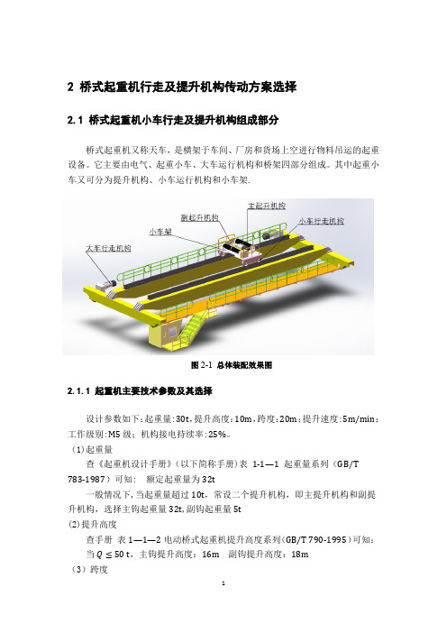
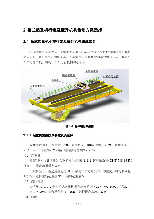
2 桥式起重机行走及提升机构传动方案选择2.1 桥式起重机小车行走及提升机构组成部分桥式起重机又称天车,是横架于车间、厂房和货场上空进行物料吊运的起重设备。
它主要由电气、起重小车、大车运行机构和桥架四部分组成。
其中起重小车又可分为提升机构、小车运行机构和小车架.图2-1总体装配效果图2.1.1 起重机主要技术参数及其选择设计参数如下:起重量:30t,提升高度:10m,跨度:20m;提升速度:5m/min;工作级别:M5级;机构接电持续率:25%。
(1)起重量查《起重机设计手册》(以下简称手册)表1-1—1 起重量系列(GB/T783-1987)可知: 额定起重量为32t一般情况下,当起重量超过10t,常设二个提升机构,即主提升机构和副提升机构,选择主钩起重量32t,副钩起重量5t(2)提升高度查手册表1—1—2电动桥式起重机提升高度系列(GB/T 790-1995)可知:当 Q≤50 t,主钩提升高度:16m副钩提升高度:18m(3)跨度查手册表1-1—6桥式起重机跨度系列(GB/T 790—1995)可知:当 Q≤50 t,有通道则起重机跨度选取22m,厂房跨度选取24m;无通道则起重机跨度选取22.5m,厂房跨度选取24m;2。
1。
2 起重机工作级别(1)起重机的使用等级按GB/T 3811-2008《起重机设计规范》,查手册表1-2—1起重机的使用等级(GB/T 3811-2008,ISO 4301-1986)可知:使用等级为 U5,对应的起重机总工作循环数 C T 满足:2.50×10⁵≤C T≤5.00×10⁵(2)起重机提升载荷状态级别载荷状态按 Q2设计,即较少吊运额定载荷,经常吊运中重载荷。
此时起重机的载荷谱系数为:0.125<K P≤0.250(3)起重机整机的工作级别查手册表1-2—4 可知:起重机整机的工作级别为 A5(4)自重载荷的估算通用双梁桥式起重机自重估算的经验公式如下:m G=0.45 m Q+0.82 S=0.45×32+0.82×22=32.44 t (2.1)起重小车的重量计算公式如下:m t=0.4 m Q=0.4×32=12.8 t (2.2)2.2 提升机构提升机构是起重机中最重要、最基本的机构,其工作的好坏直接影响整台机器的性能。
毕业论文:桥式起重机运行机构设计(终稿)

摘要本文主要介绍了桥式起重机的整体设计理论和设计过程,其中重点设计了桥式起重机的运行机构起升机构等,主要包括桥式起重机小车运行机构的整体设计及传动机构的布置,小车运行机构计算。
还有轴承的选择、联轴器的选择、电动机的选择、减速器的选择和校核。
关键词:桥式起重机;起重机小车;卷筒;减速器。
AbstractThis article mainly introduced the entire design theory and design process of bridge-type hoist crane,which focused on the design of the bridgecrane operation of institutions and hoisting mechanism.The overalldesign that mainly includes the bridge type derrick small car to circulate organization and spread the decoration that the motive reaches, the small car circulates an organization calculation.Still have the choice of the choice, electric motor of the choice, allied stalk machine of bearings, decelerate machine of choice and pit in the school.Keyword:Bridge type derrick;The derrick small car;Book tube;Decelerate a machine.目录摘要 (1)Abstract (2)第一章概述 (6)1.1概论 (6)1.2起重机介绍 (6)1.2.1起重机的类型及特点 (7)1.3桥式起重机发展概述 (7)1.3.1国外桥式起重机发展动向 (7)1.3.2国内桥式起重机发展动向 (8)第二章桥式起重介绍 (8)2.1 桥式起重机的特点和分类 (9)2.1.1 通用桥式起重机 (9)2.1.2专用桥式起重机 (9)2.1.3 电动葫芦型桥式起重机 (10)2.2桥式起重机的组成和特点 (11)2.2.1桥式起重机小车 (11)2.2.3桥式起重机小车运行传动机构 (11)2.3 桥式起重机运行机设计的目的;内容和要求 (11)2.3.1设计目的 (11)2.3.2设计内容 (12)2.3.3设计要求 (12)第三章小车运行机构的计算 (13)3.2 选择车轮与轨道并验算起强度 (14)3.3 运行阻力的计算 (16)3.4 选择电动机 (16)3.5 验算电动机发热条件 (17)3.6 选择减速器 (18)3.7 验算运行机构速度和实际所需功率 (18)3.8 验算启动时间 (18)3.9 按起动工况校核减速器功率 (19)3.10验算起动不打滑条件 (19)3.11 选择制动器 (20)3.12 演算制动不打滑条件 (21)3.13选择联轴器 (21)3.14 演算低速浮动轴强度 (22)第四章大车运行机构的计算 (24)4.1设计的基本原则和要求 (24)4.1.1 机构传动方案 (24)4.1.2 大车运行机构具体布置的主要问题 (24)4.2大车运行机构的计算 (25)4.2.2 选择车轮与轨道,并验算其强度 (26)4.2.3 运行阻力计算 (28)4.2.4 选择电动机 (28)4.2.5 验算电动机的发热功率条件 (29)4.2.6 减速器的选择 (29)4.2.7 验算运行速度和实际所需功率 (30)4.2.8 验算起动时间 (31)4.2.9 起动工况下校核减速器功率 (31)4.2.10 验算启动不打滑条件 (32)4.2.11 选择制动器 (33)4.2.12 选择联轴器 (34)4.2.13 浮动轴的验算 (35)第五章结论 (36)参考文献 (37)致谢 (37)参考资料 (38)第1章概述1.1 概论桥式起重机是桥架型起重机的一种,它依靠起升机构和在水平面内的两个相互垂直方向移动的运行机构,能在矩形场地及其上空作业,是工矿企业广泛使用的一种起重运输机械。
徐文龙-QZ20桥式起重机桥架及大车运行机构设计

徐文龙-QZ20桥式起重机桥架及大车运行机构设计1 前言1.1 起重机简介[1]桥式起重机是桥架在高架轨道上运行的一种桥架型起重机,又称天车。
桥式起重机的桥架沿铺设在两侧高架上的轨道纵向运行,起重小车沿铺设在桥架上的轨道横向运行,构成一矩形的工作范围,就可以充分利用桥架下面的空间吊运物料,不受地面设备的阻碍。
桥式起重机广泛地应用在室内外仓库、厂房、码头和露天贮料场等处。
桥式起重机可分为普通桥式起重机、简易粱桥式起重机和冶金专用桥式起重机三种。
普通桥式起重机一般由起重小车、桥架运行机构、桥架金属结构组成。
起重小车又由起升机构、小车运行机构和小车架三部分组成。
起升机构包括电动机、制动器、减速器、卷筒和滑轮组。
电动机通过减速器,带动卷筒转动,使钢丝绳绕上卷筒或从卷筒放下,以升降重物。
小车架是支托和安装起升机构和小车运行机构等部件的机架,通常为焊接结构。
起重机运行机构的驱动方式可分为两大类:一类为集中驱动,即用一台电动机带动长传动轴驱动两边的主动车轮;另一类为分别驱动、即两边的主动车轮各用一台电动机驱动。
中、小型桥式起重机较多采用制动器、减速器和电动机组合成一体的“三合一”驱动方式,大起重量的普通桥式起重机为便于安装和调整,驱动装置常采用万向联轴器。
起重机运行机构一般只用四个主动和从动车轮,如果起重量很大,常用增加车轮的办法来降低轮压。
当车轮超过四个时,必须采用铰接均衡车架装置,使起重机的载荷均匀地分布在各车轮上。
桥架的金属结构由主粱和端粱组成,分为单主粱桥架和双粱桥架两类。
单主粱桥架由单根主粱和位于跨度两边的端粱组成,双粱桥架由两根主粱和端粱组成。
主粱与端粱刚性连接,端粱两端装有车轮,用以支承桥架在高架上运行。
主粱上焊有轨道,供起重小车运行。
桥架主粱的结构类型较多比较典型的有箱形结构、四桁架结构和空腹桁架结构。
箱形结构又可分为正轨箱形双粱、偏轨箱形双粱、偏轨箱形单主粱等几种。
正轨箱形双粱是广泛采用的一种基本形式,主粱由上、下翼缘板和两侧的垂直腹板组成,小车钢轨布置[2]在上翼缘板的中心线上,它的结构简单,制造方便,适于成批生产,但自重较大。
桥式起重机机构设计

2 桥式起重机行走及提升机构传动方案选择2.1 桥式起重机小车行走及提升机构组成部分桥式起重机又称天车,是横架于车间、厂房和货场上空进行物料吊运的起重设备。
它主要由电气、起重小车、大车运行机构和桥架四部分组成。
其中起重小车又可分为提升机构、小车运行机构和小车架。
图2-1总体装配效果图2.1.1 起重机主要技术参数及其选择设计参数如下:起重量:30t,提升高度:10m,跨度:20m;提升速度:5m/min;工作级别:M5级;机构接电持续率:25%。
(1)起重量查《起重机设计手册》(以下简称手册)表1-1-1 起重量系列(GB/T 783-1987)可知:额定起重量为32t一般情况下,当起重量超过10t,常设二个提升机构,即主提升机构和副提升机构,选择主钩起重量32t,副钩起重量5t(2)提升高度查手册表1-1-2电动桥式起重机提升高度系列(GB/T 790-1995)可知:当 Q≤50 t,主钩提升高度:16m副钩提升高度:18m(3)跨度查手册表1-1-6桥式起重机跨度系列(GB/T 790-1995)可知:当 Q≤50 t,有通道则起重机跨度选取22m,厂房跨度选取24m;无通道则起重机跨度选取22.5m,厂房跨度选取24m;2.1.2 起重机工作级别(1)起重机的使用等级按GB/T 3811-2008《起重机设计规范》,查手册表1-2-1起重机的使用等级(GB/T 3811-2008,ISO 4301-1986)可知:使用等级为 U5,对应的起重机总工作循环数 C T 满足:2.50×10⁵≤C T≤5.00×10⁵(2)起重机提升载荷状态级别载荷状态按 Q2设计,即较少吊运额定载荷,经常吊运中重载荷。
此时起重机的载荷谱系数为:0.125<K P≤0.250(3)起重机整机的工作级别查手册表1-2-4 可知:起重机整机的工作级别为 A5(4)自重载荷的估算通用双梁桥式起重机自重估算的经验公式如下:m G=0.45 m Q+0.82 S=0.45×32+0.82×22=32.44 t (2.1)起重小车的重量计算公式如下:m t=0.4 m Q=0.4×32=12.8 t (2.2)2.2 提升机构提升机构是起重机中最重要、最基本的机构,其工作的好坏直接影响整台机器的性能。
10t单梁桥式起重机大车运行机构的设计全套图纸

优秀设计毕业论文(设计)任务书学生姓名学号年级专业及班级指导教师及职称学部20XX年9月20日填写说明一、毕业论文(设计)任务书是学院依照已经确信的毕业论文(设计)题目下达给学生的一种教学文件,是学生在指导教师指导下独立从事毕业论文(设计)工作的依据。
此表由指导教师填写。
二、此任务书必需针对每一名学生,不能多人共用。
三、选题要适当,任务要明确,难度要适中,分量要合理,使每一个学生在规定的时限内,通过自己的尽力,能够完成任务书规定的设计研究内容。
四、任务书一经下达,不得随意更改。
五、各栏填写大体要求。
(一)要紧内容和要求:1.工程设计类选题明确设计具体任务,设计原始条件及要紧技术指标;设计方案的形成(比较与论证);该生的偏重点;应完成的工作量,如图纸、译文及运算机应用等要求。
2.实验研究类选题明确选题的来源,具体任务与目标,国内外相关的研究现状及其评述;该生的研究重点,研究的实验内容、实验原理及实验方案;运算机应用及工作量要求,如论文、文献综述报告、译文等。
3.文法经管类论文明确选题的任务、方向、研究范围和目标;对相关的研究历史和研究现状简要介绍,明确该生的研究重点;要求完成的工作量,如论文、文献综述报告、译文等。
(二)要紧参考文献与外文资料:在确信了毕业论文(设计)题目和明确了要求后,指导教师应给学生提供一些相关资料和相关信息,或划定参考资料的范围,指导学生搜集反映当前研究进展的近1-3年参考资料和文献。
外文资料是指导教师依照选题情形明确学生需要阅读或翻译成中文的外文文献。
(三)毕业论文(设计)的进度安排:1.设计类、实验研究类课题实习、调研、搜集资料、方案制定约占总时刻的20%;主体工作,包括设计、计算、绘制图纸、实验及结果分析等约占总时刻的50%;撰写初稿、修改、定稿约占总时刻的30%。
2.文法经管类论文实习、调研、资料搜集、归档整理、形成提纲约占总时刻的60%;撰写论文初稿,修改、定稿约占总时刻的40%。
桥式起重机机构设计
2 桥式起重机行走及提升机构传动方案选择2.1 桥式起重机小车行走及提升机构组成部分桥式起重机又称天车,是横架于车间、厂房和货场上空进行物料吊运的起重设备。
它主要由电气、起重小车、大车运行机构和桥架四部分组成。
其中起重小车又可分为提升机构、小车运行机构和小车架。
图2-1总体装配效果图2.1.1 起重机主要技术参数及其选择设计参数如下:起重量:30t,提升高度:10m,跨度:20m;提升速度:5m/min;工作级别:M5级;机构接电持续率:25%。
(1)起重量查《起重机设计手册》(以下简称手册)表1-1-1 起重量系列(GB/T 783-1987)可知:额定起重量为32t一般情况下,当起重量超过10t,常设二个提升机构,即主提升机构和副提升机构,选择主钩起重量32t,副钩起重量5t(2)提升高度查手册表1-1-2电动桥式起重机提升高度系列(GB/T 790-1995)可知:当 Q≤50 t,主钩提升高度:16m副钩提升高度:18m(3)跨度查手册表1-1-6桥式起重机跨度系列(GB/T 790-1995)可知:当 Q≤50 t,有通道则起重机跨度选取22m,厂房跨度选取24m;无通道则起重机跨度选取22.5m,厂房跨度选取24m;2.1.2 起重机工作级别(1)起重机的使用等级按GB/T 3811-2008《起重机设计规范》,查手册表1-2-1起重机的使用等级(GB/T 3811-2008,ISO 4301-1986)可知:使用等级为 U5,对应的起重机总工作循环数 C T 满足:2.50×10⁵≤C T≤5.00×10⁵(2)起重机提升载荷状态级别载荷状态按 Q2设计,即较少吊运额定载荷,经常吊运中重载荷。
此时起重机的载荷谱系数为:0.125<K P≤0.250(3)起重机整机的工作级别查手册表1-2-4 可知:起重机整机的工作级别为 A5(4)自重载荷的估算通用双梁桥式起重机自重估算的经验公式如下:m G=0.45 m Q+0.82 S=0.45×32+0.82×22=32.44 t (2.1)起重小车的重量计算公式如下:m t=0.4 m Q=0.4×32=12.8 t (2.2)2.2 提升机构提升机构是起重机中最重要、最基本的机构,其工作的好坏直接影响整台机器的性能。
(完整版)桥式起重机运行机构大车设计

东北林业大学起重机械课程设计学院工程技术学院专业班级08级森工三班姓名XXX学号********指导老师孟春组号21000设计部分大车运行机构2011年7 月16 日起重机设计参数最大额定起重量Q (t): 32 跨度L (m ):28大车运行速度0v (m/s ): 0.5 工作级别: M4JC%值: 40大车运行机构:采用分别传动的方案方案:采用4车轮、对面布置、分别驱动。
部件:电机、减速器、联轴器、车轮、轨道。
桥架自重G =0.45Q+0.82L=37.36t=373.6kN ,小车自重q=0.4Q=12.8t=128kN ,小车运行极限位置距轨道中心线距离l=2m 。
(1)车轮与轨道满载最大轮压:L lL q Q p -•++=24q -G max =269.4kN 空载最大轮压: L lL q p -•+=24q -G max ’=120.8kN 空载最小轮压:Llq •+=24q -G Pmin = =66kN使用双轮缘车轮,轮缘高为25mm —30mm 。
根据工作级别M4,G Q /=0.86,大车运行速度30m/min ,初选车轮踏面直径,车轮材料,轨道及其材料。
根据表3-8-12查得:车轮直径700mm ,轨道型号QU70,许用轮压30.7t ,车轮材料ZG310-570、HB320。
轴承型号为7524 车轮踏面疲劳验算:按照点接触验算 疲劳计算载荷:=+=32minmax P P P c 201.6kN=21322C C m R K 535.4kN式中。
-2K 与材料有关的许用点接触应力常数(N/mm 2);根据表3-8-6选取,K 2=0.1;R —曲率半径,取车轮曲率半径与轨面曲率半径中之大值(mm ),R =700mm ;m —有轨道顶面与车轮的曲率半径之比(r/R )所确定的系数,根据表3-8-9选取,m =0.468。
-1C 转速系数,根据表3-8-7选取,C 1=1; -2C 工作级别系数,根据表3-8-8选取, C 2=1.12。
10t电动双梁桥式起重机技术规格书10.30

10t电动双梁桥式起重机技术规格书10.30大连重工技术规格书科室:冶炼主任设计师:陈雷联系电话:__-__ 所属产品名称:5MVA精炼电炉主车间图纸代码:采购配套件名称:10t电动双梁桥式起重机技术要求:1 设备型号、规格及技术参数;2 有■、无□订货图(见附页第□页);(如事业部招议标采购时不能满足本件所提出技术要求应及时向主任设计师反馈。
)1设备型号:10t电动双梁桥式起重机2.设备数量:1台3.设备用途:用于精炼炉主厂房设备起吊搬运4.设备的技术要求4.1环境要求:设备使用地区的海拔高度:+7m设备使用地区的环境温度:年平均气温21.9℃,绝对最高气温37.5℃绝对最低气温1.1℃月平均最高气温28.3℃月平均最低气温13.4℃地震设防烈度:6度使用环境条件:常温,多尘。
4.2主要技术参数:起重量:10t跨度:14.5 m起升高度:24 m工作级别:A5起升速度:12m/min小车运行速度:35m/min大车运行速度:60m/min小车供电: 工字钢滑车电缆导电大车供电: 型钢滑触线(三相四线制,土建负责)大车行程:30m控制方式:地面操纵缓冲器高度:H=520mm大车轨道:43kg/m最大轮压:~102kN编制:王奕昀审核:张彦萍批准:徐洪泽表18大连重工技术规格书电源:AC 380V 50Hz4.3 电动机为起重机专用电动机,采用大连布鲁克、伯顿或佳木斯电机产品,额定电压380V,额定频率50Hz,绝缘等级为F级,防护等级IP54。
4.4制动器为电动液压推杆轮式常闭结构,附有松闸显示开关、手动释放装置。
当机构不工作时制动器闭合,机构工作时由松闸装置将制动器打开,安全可靠。
起升制动器安全系数不小于2倍,运行机构的制动器每个安全系数均不小于1.75,推杆型号均为ED型。
4.5 卷筒采用Q345-B的优质合金钢焊接而成,焊后进行时效处理,消除应力。
卷筒两端设有大于两圈的安全圈和三圈固定圈。
10t-LD型单梁桥式起重机总体及起升机构设计

4)了解国内外桥式起重机发展状况及技术水平,并具有一定的分析、比较能力。
5)其它各项应符合本资料有关部分提出的要求;
2、本毕业设计(论文)课题任务的内容和要求(包括原始数据、技术要求、工作要求等):
(1)设计任务:
①总体设计:
A.总体方案及总体参数的确定(包括方案的比较);
C.重物起升、小车和大车平移驱动能力计算及驱动元件的选择;
②起重小车的设计:
A.起升机构的设计及钢丝绳的选择;
B.起重小车驱动机构设计及行走轮接触强度的校核计算;
C.起重小车结构刚度、强度的校核计算;
③典型零件设计及加工工艺卡的编制;
(2)技术参数及要求:
①额定起重量:10吨;
②起升高度9m;大车轨道跨度12m;
③起升和小车运行均采用单速,速度为0.6m/s;大车运行为3级速度控制,最大为1.5m/s;最小为0.6m/s;
④重物起升采用标准电动葫芦,大车采用分立驱动型式;
[VII]机械零件课程设计·贵州人民出版社;
[Ⅷ]吉林工业大学主编·工程机械液压与液力传动·北京:机械工业出版社,1986;
[Ⅸ]液压传动设计手册·上海科技出版社;
[Ⅹ]东北工学院编·械设计手册·北京:机械工业出版社;
[Ⅻ]何利民主编·电工手册·北京:中国建筑工业出版社,1993。
3、对本毕业设计(论文)课题成果的要求(包括图表、实物等硬件要求):
①计算说明书一份
内容包括:设计任务要求的选型论证、设计计算内容,毕业实习报告等。做到内容完整,论证充分(包括经济性论证),字迹清楚,插图和表格正规(分别进行统一编号)、准确,字数要求不少于2万字。查阅文献15篇以上,翻译机械类外文资料,译文字数不少于5000字;撰写中英文摘要;并引导学生应用计算机进行设计、计算与绘图。
10吨桥式起重机设计
毕业论文10t桥式起重机小车起升机构作者姓名颜景熠指导导师姓名纪宏毕业班级冶机072 学科类别工学学科专业名称冶金机械论文提交日期2007年6 论文答辩日期2007.06.20答辩委员会成员评阅人辽宁科技学院2007年6A Thesis in Metallurgical MachinerySteel Roll Machineryby Yan JingyiSupervisor:Prelector JiHongJune 2007毕业设计(论文)任务书毕业设计论文题目:10t桥式起重机大车运行机构毕业设计论文内容: 1.传动方案选择2.起重机力能参数计算3.常用标准件选择计算4.主要零件疲劳强度计算5.编写设计说明书毕业设计论文专题部分:指导教师:签字年月日教研室主任:签字年月日系主任:签字年月日毕业设计论文评语指导教师评语:成绩:指导教师:(签字)年月日评阅人评语:成绩:指导教师:(签字)年月日毕业设计论文答辩成绩及总成绩评定毕业设计论文答辩委员会成员于年月日审查了专业学生的毕业设计论文论文题目:10t桥式起重机大车运行机构设计论文专题:起重机大车超载限制器设计论文说明书共15 页,设计图纸共 2 张指导教师:纪宏评阅人:毕业设计论文答辩委员会意见:答辩成绩:总成绩:答辩委员会主任委员:年月日摘要桥式起重机运行大车中最主要的结构有:电动机,减速器,联轴器,等等。
桥式起重机的大车设有起升机构和小车运行机构,为使小车轮压呈均匀分布,应对大车的机构布置进行优化设计,以知大车轨迹和轴矩为例,以车轮轮压均匀分配为目标函数,按单钩起重大车的条件提出约束条件,对优化设计的结果进行分析如下:首先,电动机——起重机械的驱动电动机要根据所需功率、最大转矩、接电持续率、起动等级、控制类型、速度变化范围、供点方式、保护等级、环境温度与使用地区海拔高度等因素进行选择。
其次,减速器——起重机械设计时,根据理论指导和工作经验,对机构形式、中心距、公称传动比及齿轮参数的选择应遵守原则和注意事项。
课程设计 -- 桥式起重机
桥式起重机课程设计一. 起重机设计的总体方案本次起重机设计的主要参数如下:起重量10t, 跨度15m, 起升高度为7m,起升速度7m/min小车运行速度v=40m/min 大车运行速度v=85m/min 大车运行传动方式为分别传动:桥架主梁型式,箱型梁,小车估计重量4t,起重机的重量16.8t。
1.起重机的介绍2.主梁跨度15 m,是由上、下盖板和两块垂直的腹板组成封闭箱形截面实体板梁连接,主梁横截面腹板的厚度为6mm,翼缘板的厚度为10mm,主梁上的走台的宽度取决于端梁的长度和达成运行机构的平面尺寸,主梁跨度中部高度取H=L/17,主梁和端梁采用搭接形式,主梁和端梁连接处的高取H0=0.4-0.6H,腹板的稳定性有横向加劲板和纵向加劲条或者角钢来维持,纵向加劲条的焊接采用连续点焊,主梁翼缘板和腹板的焊接采用贴角焊缝,主梁通常会产生下挠变形,但加工和装配时采用预制上拱。
大车的设计一.设计的基本原则和要求大车运行机构的设计通常和桥架的设计一起考虑,两者的设计工作要交叉进行,一般的设计步骤:1. 确定桥架结构的形式和大车运行机构的传方式2. 布置桥架的结构尺寸3. 安排大车运行机构的具体位置和尺寸4. 综合考虑二者的关系和完成部分的设计对大车运行机构设计的基本要求是:1. 机构要紧凑,重量要轻2. 和桥架配合要合适,这样桥架设计容易,机构好布置3. 尽量减轻主梁的扭转载荷,不影响桥架刚度4. 维修检修方便,机构布置合理二.大车运行机构具体布置大车运行机构的零部件时应该注意以几点:1. 因为大车运行机构要安装在起重机桥架上,桥架的运行速度很高,而且受载之后向下挠曲,机构零部件在桥架上的安装可能不十分准确,所以如果单从保持机构的运动性能和补偿安装的不准确性着眼,凡是靠近电动机、减速器和车轮的轴,最好都用浮动轴。
2. 为了减少主梁的扭转载荷,应该使机构零件尽量靠近主梁而远离走台栏杆;尽量靠近端梁,使端梁能直接支撑一部分零部件的重量。
桥式起重机运行机构设计
此次设计的起重机为工厂加工车间使用的电动双梁吊钩桥式起重机。已知数据: 起重量Q=10t,小车运行速度Vc=45 m min,工作级别,机构接电持续率JC= 25%, 小车质量估计Gxc=4t。輒峄陽檉簖疖網儂號泶。
3
3.1小车运行机构的传动方案
具有四个车轮的其中半数为主动轮的小车运行机构,有闭式传动和带有开式齿轮 的传动两种。由于开式齿轮易于磨损,因此现代起重机已很少采用。闭式齿轮传动的 方案如图1、图2所示。在这些方案中,齿轮易于维护保养,齿轮传动构成独立的减速 器部件,机构的装拆分组性较好。尧侧閆繭絳闕绚勵蜆贅。
(1)电动梁式起重机 其特点是用自行式电动葫芦替代通用桥式起重机的起重小车,用电动葫芦的运行 小车在单根主梁的工字钢下突缘上运行,跨度小时直接用工字钢作主梁,跨度大时可 在主梁工字钢的上面再作水平加强,形成的组合断面主梁。其主梁可以是单根主梁, 也可以是两根主梁,其桥架可以是像通用桥式起重机那样通过运行装置直接支撑在高 架轨道上,也可以通过运行装置悬挂在房顶下面的架空轨道上。
桥架两端通过运行装置直接支撑在高架轨道上的桥架型起重机,称为“桥式起重 机”。
桥式起重机一般由装有大车运行机构的桥架、装有起升机构和小车运行机构的起 重小车、电气设备、司机室等几个大部分组成。外形像一个两端支撑在平行的两条架 空轨道上平移运行的单跨平板桥。起升机构用来垂直升降物品,起重小车用来带着载 荷作横向运动;桥架和大车运行机构用来将起重小车和物品作纵向移动。
(5)双小车桥式起重机 这种起重机与吊钩桥式起重机基本相同,只是在桥架上装有2台起重量相同的小 车。这种机型用于吊运与装卸长形物件。坛摶乡囂忏蒌鍥铃氈淚。
2.1.2专用桥式起重机
(1)冶金桥式起重机 冶金桥式起重机根据用途可以划分为不同的类型,主要结构基本与通用吊钩桥式 起重机相同,取物装置多为专用。主要用于冶金车间的吊运作业,其起重量很大,最 大的可达到数百吨。
- 1、下载文档前请自行甄别文档内容的完整性,平台不提供额外的编辑、内容补充、找答案等附加服务。
- 2、"仅部分预览"的文档,不可在线预览部分如存在完整性等问题,可反馈申请退款(可完整预览的文档不适用该条件!)。
- 3、如文档侵犯您的权益,请联系客服反馈,我们会尽快为您处理(人工客服工作时间:9:00-18:30)。
十吨位桥式起重机大车运行机构设计毕业设计(论文)相关资料题目:十吨位桥式起重机大车运行机构设计目录一、毕业设计(论文)开题报告二、毕业设计(论文)外文资料翻译及原文三、学生“毕业论文(论文)计划、进度、检查及落实表”四、实习鉴定表无锡太湖学院毕业设计(论文)开题报告题目:十吨位桥式起重机大车运行机构设计信机系机械工程及自动专业学号: 0923087学生姓名:叶宏城指导教师:陈炎冬(职称:讲师)(职称:)2012年11月25日外文资料翻译及原文英文原文:Fatigue life prediction of the metalwork of a travelling gantrycraneAbstractIntrinsic fatigue curves are applied to a fatigue life prediction problem of the metalwork of a traveling gantry crane. A crane, used in the forest industry, was studied in working conditions at a log yard, an strain measurements were made. For the calculations of the number of loading cycles, the rain flow cycle counting technique is used. The operations of a sample of such cranes were observed for a year for the average number of operation cycles to be obtained. The fatigue failure analysis has shown that failures some elements are systematic in nature and cannot be explained by random causes.卯1999 Elsevier Science Ltd. All rights reserved.Key words: Cranes; Fatigue assessment; Strain gauging1. IntroductionFatigue failures of elements of the metalwork of traveling gantry cranes LT62B are observed frequently in operation. Failures as fatigue cracks initiate and propagate in welded joints of the crane bridge and supports in three-four years. Such cranes are used in the forest industry at log yards for transferring full-length and sawn logs to road trains, having a load-fitting capacity of 32 tons. More than 1000 cranes of this type work at the enterprises of the Russian forest industry. The problem was stated to find the weakest elements limiting the cranes' fives, predict their fatigue behavior, and give recommendations to the manufacturers for enhancing the fives of the cranes.2. Analysis of the crane operationFor the analysis, a traveling gantry crane LT62B installed at log yard in the Yekaterinburg region was chosen. The crane serves two saw mills, creates a log store, and transfers logs to or out of road trains. A road passes along the log store. The saw mills are installed so that the reception sites are under the crane span. A schematic view of the crane is shown in Fig. 1.1350-6307/99/$一see front matter 1999 Elsevier Science Ltd. All rights reserved. PII: S 1 3 5 0一6307(98) 00041一7A series of assumptions may be made after examining the work of cranes:·if the monthly removal of logs from the forest exceeds the processing rate, i.e. there is a creation of a log store, the crane expects work, being above the centre of a formed pile with the grab lowered on the pile stack;·when processing exceeds the log removal from the forest, the crane expects work above an operational pile close to the saw mill with the grab lowered on the pile; ·the store of logs varies; the height of the piles is considered to be a maximum;·the store variation takes place from the side opposite to the saw mill;·the total volume of a processed load is on the average k=1.4 times more than the total volume of removal because of additional transfers.2.1. Removal intensityIt is known that the removal intensity for one year is irregular and cannot be considered as a stationary process. The study of the character of non-stationary flow of road trains at 23 enterprises Sverdlesprom for five years has shown that the monthly removal intensity even for one enterprise essentially varies from year to year. This is explained by the complex of various systematic and random effects which exert an influence on removal: weather conditions, conditions of roads and lorry fleet, etc. All wood brought to the log store should, however, be processed within one year. Therefore, the less possibility of removing wood in the season between spring and autumn, the more intensively the wood removal should be performed in winter. While in winter the removal intensity exceeds the processing considerably, in summer, in most cases, the more full-length logs are processed than are taken out.From the analysis of 118 realizations of removal values observed for one year, it is possible to evaluate the relative removal intensity g(t) as percentages of the annualload turnover. The removal data fisted in Table 1 is considered as expected values for any crane, which can be applied to the estimation of fatigue life, and, particularly, for an inspected crane with which strain measurement was carried out (see later). It would be possible for each crane to take advantage of its load turnover per one month, but to establish these data without special statistical investigation is difficult. Besides, to solve the problem of life prediction a knowledge of future loads is required, which we take as expected values on cranes with similar operation conditions.The distribution of removal value Q(t) per month performed by the relative intensityq(t) is written aswhere Q is the annual load turnover of a log store, A is the maximal designed store of logs in percent of Q. Substituting the value Q, which for the inspected crane equals 400,000 m3 per year, and A=10%, the volumes of loads transferred by the crane are obtained, which are listed in Table 2, with the total volume being 560,000 m3 for one year using K,.2.2. Number of loading blocksThe set of operations such as clamping, hoisting, transferring, lowering, and getting rid of a load can be considered as one operation cycle (loading block) of the crane. As a result to investigations, the operation time of a cycle can be modeled by the normal variable with mean equal to 11.5 min and standard deviation to 1.5 min. unfortunately, this characteristic cannot be simply used for the definition of the number of operation cycles for any work period as the local processing is extremely irregular. Using a total operation time of the crane and evaluations of cycle durations, it is easy to make large errors and increase the number of cycles compared with the real one. Therefore, it is preferred to act as follows.The volume of a unit load can be modeled by a random variable with a distribution function(t) having mean22 m3 and standard deviation 6;一3 m3, with the nominalvolume of one pack being 25 m3. Then, knowing the total volume of a processed load for a month or year, it is possible to determine distribution parameters of the number of operation cycles for these periods to take advantage of the methods of renewal theory [1].According to these methods, a random renewal process as shown in Fig. 2 is considered, where the random volume of loads forms a flow of renewals:In renewal theory, realizations of random:,,,having a distribution function F-(t),are understoodas moments of recovery of failed units or request receipts. The value of a processedload:,,after}th operation is adopted here as the renewal moment.<t﹜. The function F-(t) is defined recurrently,Let F(t)=P﹛nLet v(t) be the number of operation cycles for a transferred volume t. In practice, the total volume of a transferred load t is essentially greater than a unit load, and it is useful therefore totake advantage of asymptotic properties of the renewal process. As follows from an appropriatelimit renewal theorem, the random number of cycles v required to transfer the large volume t hasthe normal distribution asymptotically with mean and variance.without dependence on the form of the distribution function月t) of a unit load (the restriction isimposed only on nonlattice of the distribution).Equation (4) using Table 2 for each averaged operation month,function of number of load cycles with parameters m,. and 6,., which normal distribution in Table 3. Figure 3 shows the average numbers of cycles with 95 % confidence intervals. The values of these parametersfor a year are accordingly 12,719 and 420 cycles.3. Strain measurementsIn order to reveal the most loaded elements of the metalwork and to determine a range of stresses, static strain measurements were carried out beforehand. Vertical loading was applied by hoisting measured loads, and skew loading was formed with a tractor winch equipped with a dynamometer. The allocation schemes of the bonded strain gauges are shown in Figs 4 and 5. As was expected, the largest tension stresses in the bridge take place in the bottom chord of the truss (gauge 11-45 MPa). The top chord of the truss is subjected to the largest compression stresses.The local bending stresses caused by the pressure of wheels of the crane trolleys are added to the stresses of the bridge and the load weights. These stresses result in the bottom chord of the I一beam being less compressed than the top one (gauge 17-75 and 10-20 MPa). The other elements of the bridge are less loaded with stresses not exceeding the absolute value 45 MPa. The elements connecting the support with the bridge of the crane are loaded also irregularly. The largest compression stresses take place in the carrying angles of the interior panel; the maximum stresses reach h0 MPa (gauges 8 and 9). The largest tension stresses in the diaphragms and angles of the exterior panel reach 45 MPa (causes 1 and hl.The elements of the crane bridge are subjected, in genera maximum stresses and respond weakly to skew loads. The suhand, are subjected mainly to skew loads.1, to vertical loads pports of the crane gmmg rise to on the otherThe loading of the metalwork of such a crane, transferring full-length logs, differs from that ofa crane used for general purposes. At first, it involves the load compliance of log packs because ofprogressive detachment from the base. Therefore, the loading increases rather slowly and smoothly.The second characteristic property is the low probability of hoisting with picking up. This is conditioned by the presence of the grab, which means that the fall of the rope from the spreader block is not permitted; the load should always be balanced. The possibility of slack being sufficient to accelerate an electric drive to nominal revolutions is therefore minimal. Thus, the forest traveling gantry cranes are subjected to smaller dynamic stresses than in analogous cranes for general purposes with the same hoisting speed. Usually, when acceleration is smooth, the detachment of a load from the base occurs in 3.5-4.5 s after switching on an electric drive. Significant oscillations of the metalwork are not observed in this case, and stresses smoothly reach maximum values.When a high acceleration with the greatest possible clearance in the joint between spreader andgrab takes place, the tension of the ropes happens 1 s after switching the electric drive on, theclearance in the joint taking up. The revolutions of the electric motors reach the nominal value inO.}r0.7 s. The detachment of a load from the base, from the moment of switching electric motorson to the moment of full pull in the ropes takes 3-3.5 s, the tensions in ropes increasing smoothlyto maximum. The stresses in the metalwork of the bridge and supports grow up to maximumvalues in 1-2 s and oscillate about an average within 3.5%.When a rigid load is lifted, the accelerated velocity of loading in the rope hanger and metalworkis practically the same as in case of fast hoisting of a log pack. The metalwork oscillations are characterized by two harmonic processes with periods 0.6 and 2 s, which have been obtained from spectral analysis. The worst case of loading ensues from summation of loading amplitudes so that the maximum excess of dynamic loading above static can be 13-14%.Braking a load, when it is lowered, induces significant oscillation of stress in the metalwork, which can be }r7% of static loading. Moving over rail joints of 3} mm height misalignment induces only insignificant stresses. In operation, there are possible cases when loads originating from various types of loading combine. The greatest load is the case when the maximum loads from braking of a load when lowering coincide with braking of the trolley with poorly adjusted brakes.4. Fatigue loading analysisStrain measurement at test points, disposed as shown in Figs 4 and 5, was carried out during the work of the crane and a representative number of stress oscillograms was obtained. Since a common operation cycle duration of the crane has a sufficient scatter with average value } 11.5min, to reduce these oscillograms uniformly a filtration was implemented to these signals, and all repeated values, i.e. while theconstruction was not subjected to dynamic loading and only static loading occurred, were rejected. Three characteristic stress oscillograms (gauge 11) are shown inFig. 6 where the interior sequence of loading for an operation cycle is visible. At first, stressesincrease to maximum values when a load is hoisted. After that a load is transferred to the necessary location and stresses oscillate due to the irregular crane movement on rails and over rail joints resulting mostly in skew loads. The lowering of the load causes the decrease of loading and forms half of a basic loading cycle.4.1. Analysis of loading process amplitudesTwo terms now should be separated: loading cycle and loading block. The first denotes one distinct oscillation of stresses (closed loop), and the second is for the set of loading cycles during an operation cycle. The rain flow cycle counting method given in Ref. [2] was taken advantage of to carry out the fatigue hysteretic loop analysis for the three weakest elements: (1) angle of the bottom chord(gauge 11), (2) I-beam of the top chord (gauge 17), (3) angle of the support (gauge 8). Statistical evaluation of sample cycle amplitudes by means of the Waybill distribution for these elements has given estimated parameters fisted in Table 4. It should be noted that the histograms of cycle amplitude with nonzero averages were reduced afterwards to equivalent histograms with zero averages.4.2. Numbers of loading cyclesDuring the rain flow cycle counting procedure, the calculation of number of loading cycles for the loading block was also carried out. While processing the oscillograms of one type, a sample number of loading cycles for one block is obtained consisting ofintegers with minimum and maximum observed values: 24 and 46. The random number of loading cycles vibe can be describedby the Poisson distribution with parameter =34.Average numbers of loading blocks via months were obtained earlier, so it is possible to find the appropriate characteristics not only for loading blocks per month, but also for the total number of loading cycles per month or year if the central limit theorem is taken advantage of. Firstly, it is known from probability theory that the addition of k independent Poisson variables gives also a random variable with the Poisson distribution with parameter k},. On the other hand, the Poisson distribution can be well approximated by the normal distribution with average}, and variation },. Secondly, the central limit theorem, roughly speaking, states that the distribution of a large number of terms, independent of the initial distribution asymptotically tends to normal. If the initial distribution of each independent term has a normal distribution, then the average and standard deviation of the total number of loading cycles for one year are equal to 423,096 and 650 accordingly. The values of k are taken as constant averages from Table 3.5. Stress concentration factors and element enduranceThe elements of the crane are jointed by semi-automatic gas welding without preliminary edge preparation and consequent machining. For the inspected elements 1 and 3 having circumferential and edge welds of angles with gusset plates, the effective stress concentration factor for fatigue is given by calculation methods [3],kf=2.}r2.9, coinciding with estimates given in the current Russian norm for fatigue of welded elements [4], kf=2.9.The elements of the crane metalwork are made of alloyed steel 09G2S having an endurance limit of 120 MPa and a yield strength of 350 MPa. Then the average values of the endurance limits of the inspected elements 1 and 3 are ES一l=41 MPa. Thevariation coefficient is taken as 0.1, and the corresponding standard deviation is 6S-、一4.1 MPa.The inspected element 2 is an I-beam pierced by holes for attaching rails to the top flange. The rather large local stresses caused by local bending also promote fatigue damage accumulation. According to tables from [4], the effective stress concentration factor is accepted as kf=1.8, which gives an average value of the endurance limit as ES 一l=h7 Map. Using the same variation coiffing dent th e stand arid d emit ion is 1s σ-=6.7 MPa.An average S-N curve, recommended in [4], has the form:with the inflexion point No=5·106 and the slope m=4.5 for elements 1 and 3 and m=5.5 for element 2.The possible values of the element endurance limits presented above overlap the ranges of load amplitude with nonzero probability, which means that these elements are subjected to fatigue damage accumulation. Then it is possible to conclude that fatigue calculations for the elements are necessary as well as fatigue fife prediction.6. Life predictionThe study has that some elements of the metalwork are subject to fatigue damage accumulation.To predict fives we shall take advantage of intrinsic fatigue curves, which are detailed in [5]and [6].Following the theory of intrinsic fatigue curves, we get lognormal life distribution densities for the inspected elements. The fife averages and standard deviations are fisted in Table 5. The lognormal fife distribution densities are shown in Fig. 7. It is seen from this table that the least fife is for element 3. Recollecting that an average number of load blocks for a year is equal to 12,719, it is clear that the average service fife of the crane before fatigue cracks appear in the welded elements is sufficient: the fife is 8.5 years for element 1, 11.5 years for element 2, and h years for element 3. However, the probability of failure of these elements within three-four years is notsmall and is in the range 0.09-0.22. These probabilities cannot be neglected, and services of design and maintenance should make efforts to extend the fife of the metalwork without permitting crack initiation and propagation.7. ConclusionsThe analysis of the crane loading has shown that some elements of the metalwork are subjectedto large dynamic loads, which causes fatigue damage accumulation followed by fatigue failures.The procedure of fatigue hfe prediction proposed in this paper involves tour parts:(1) Analysis of the operation in practice and determination of the loading blocks for some period.(2) Rainflow cycle counting techniques for the calculation of loading cycles for a period of standard operation.(3) Selection of appropriate fatigue data for material.(4) Fatigue fife calculations using the intrinsic fatigue curves approach.The results of this investigation have been confirmed by the cases observed in practice, and the manufacturers have taken a decision about strengthening the fixed elements to extend their fatigue lives.References[1] Feller W. An introduction to probabilistic theory and its applications, vol. 2. 3rd ed. Wiley, 1970.[2] Rychlik I. International Journal of Fatigue 1987;9:119.[3] Piskunov V(i. Finite elements analysis of cranes metalwork. Moscow: Mashinostroyenie, 1991 (in Russian).[4] MU RD 50-694-90. Reliability engineering. Probabilistic methods of calculations for fatigue of welded metalworks.Moscow: (iosstandard, 1990 (in Russian).[5] Kopnov VA. Fatigue and Fracture of Engineering Materials and Structures 1993;16:1041.[6] Kopnov VA. Theoretical and Applied Fracture Mechanics 1997;26:169.中文翻译龙门式起重机金属材料的疲劳强度预测摘要内在的疲劳曲线应用到龙门式起重机金属材料的疲劳寿命预测问题。