HMDL1000V直流塑壳断路器-EATONMoeller伊顿
美国电缆工业Eaton公司Moeller系列PKZM0三极保护断路器说明书

Eaton 265330Eaton Moeller® series PKZM0 Motor-protective circuit-breaker, 3p, Ir=0.1-0.16A, thumb grip lockableGeneral specificationsEaton Moeller® series PKZM0 Motor-protective circuit-breaker265330PKZM0-0,16/AK401508265330976 mm 93 mm 45 mm 0.25 kgCSA-C22.2 No. 60947-4-1-14 CSA Class No.: 3211-05 UL 60947-4-1 CSAIEC/EN 60947 IEC/EN 60947-4-1 ULCSA File No.: 165628UL Category Control No.: NLRV CEUL File No.: E36332 VDE 0660Product NameCatalog Number Model Code EANProduct Length/Depth Product Height Product Width Product Weight CertificationsTurn buttonPhase-failure sensitivity (according to IEC/EN 60947-4-1, VDE 0660 Part 102)Motor protectionPhase failure sensitiveThree-pole ATEX dust-ex-protection, PTB 10, ATEX 3013, Ex II(2) GD100,000 operations (at 400V, AC-3)100,000 Operations (Main conducting paths)Can be snapped on to IEC/EN 60715 top-hat rail with 7.5 or15 mm height.40 Operations/hIII3Motor protective circuit breakerFinger and back-of-hand proof, Protection against direct contact when actuated from front (EN 50274)6000 V AC25 g, Mechanical, according to IEC/EN 60068-2-27, Half-sinusoidal shock 10 msAlso motors with efficiency class IE3Branch circuit: Manual type E if used with terminal, or suitable for group installations, (UL/CSA)-25 - 55 °C, Operating range≤ 0.25 %/K, residual error for T > 40°-5 - 40 °C to IEC/EN 60947, VDE 0660Actuator type Features Functions Number of poles Explosion safety category for dust Lifespan, electricalLifespan, mechanicalMounting positionOperating frequencyOvervoltage categoryPollution degreeProduct categoryProtectionRated impulse withstand voltage (Uimp) Shock resistanceSuitable forTemperature compensationAltitude Terminal capacity (flexible with ferrule)Max. 2000 m-25 °C55 °C25 °C40 °C40 °C80 °CDamp heat, cyclic, to IEC 60068-2-30 Damp heat, constant, to IEC 60068-2-781 x (1 - 6) mm², ferrule to DIN 462282 x (1 - 6) mm², ferrule to DIN 462281 x (1 - 6) mm²2 x (1 - 6) mm²18 - 1010 mm1 Nm, Screw terminals, Control circuit cables 1.7 Nm, Screw terminals, Main cable50 Hz60 Hz0.16 A0 kW0 kW690 V690 V0.16 A60 kA DC, up to 250 V DC, Main conducting paths50 kA, 600 V High Fault, Fuse, SCCR (UL/CSA)600 A, 600 V High Fault, max. Fuse, SCCR (UL/CSA) Screw terminalsAmbient operating temperature - minAmbient operating temperature - maxAmbient operating temperature (enclosed) - min Ambient operating temperature (enclosed) - max Ambient storage temperature - minAmbient storage temperature - maxClimatic proofing Terminal capacity (solid)Terminal capacity (solid/stranded AWG)Stripping length (main cable)Tightening torqueRated frequency - minRated frequency - maxRated operational current (Ie)Rated operational power at AC-3, 220/230 V, 50 Hz Rated operational power at AC-3, 380/400 V, 50 Hz Rated operational voltage (Ue) - minRated operational voltage (Ue) - maxRated uninterrupted current (Iu)Short-circuit currentShort-circuit current rating (group protection)Connection50 kA, 600 V High Fault, CB, SCCR (UL/CSA)600 A, 600 V High Fault, max. CB, SCCR (UL/CSA)Accessories required BK25/3-PKZ0-E65 kA, 240 V, SCCR (UL/CSA)65 kA, 480 Y/277 V, SCCR (UL/CSA)50 kA, 600 Y/347 V, SCCR (UL/CSA)Basic device fixed 15.5 x Iu, Trip Blocks2.5 A, Irm, Setting range max.± 20% tolerance, Trip blocks 0.1 A0.16 AOverload trigger: tripping class 10 A5.39 W0 W1.8 W0.16 A0 WMeets the product standard's requirements.Meets the product standard's requirements.Meets the product standard's requirements.Meets the product standard's requirements.Meets the product standard's requirements.Does not apply, since the entire switchgear needs to be evaluated.Does not apply, since the entire switchgear needs to be evaluated.Meets the product standard's requirements.Short-circuit current rating (type E) Short-circuit release Overload release current setting - minOverload release current setting - maxTripping characteristicEquipment heat dissipation, current-dependent PvidHeat dissipation capacity PdissHeat dissipation per pole, current-dependent PvidRated operational current for specified heat dissipation (In) Static heat dissipation, non-current-dependent Pvs10.2.2 Corrosion resistance10.2.3.1 Verification of thermal stability of enclosures10.2.3.2 Verification of resistance of insulating materials to normal heat10.2.3.3 Resist. of insul. mat. to abnormal heat/fire by internal elect. effects10.2.4 Resistance to ultra-violet (UV) radiation10.2.5 Lifting10.2.6 Mechanical impact10.2.7 InscriptionsDoes not apply, since the entire switchgear needs to be evaluated.Meets the product standard's requirements.Does not apply, since the entire switchgear needs to be evaluated.Does not apply, since the entire switchgear needs to be evaluated.Is the panel builder's responsibility.Is the panel builder's responsibility.Is the panel builder's responsibility.Is the panel builder's responsibility.Is the panel builder's responsibility.The panel builder is responsible for the temperature rise calculation. Eaton will provide heat dissipation data for the devices.Is the panel builder's responsibility. The specifications for the switchgear must be observed.Is the panel builder's responsibility. The specifications for the switchgear must be observed.The device meets the requirements, provided the information in the instruction leaflet (IL) is observed.Motor Starters in System xStart - brochureSave time and space thanks to the new link module PKZM0-XDM32MESwitching and protecting motors - catalogProduct Range Catalog Switching and protecting motorseaton-manual-motor-starters-characteristic-characteristic-curve.eps eaton-manual-motor-starters-characteristic-characteristic-curve-009.eps eaton-manual-motor-starters-characteristic-characteristic-curve-008.epsDA-DC-00004892.pdfDA-DC-00004921.pdfeaton-manual-motor-starters-pkz-dimensions-002.epseaton-manual-motor-starters-pkz-dimensions.epseaton-manual-motor-starters-mounting-3d-drawing-002.epseaton-general-ie-ready-dilm-contactor-standards.epseaton-manual-motor-starters-pkzm0-3d-drawing-008.epseaton-manual-motor-starters-pkzm0-3d-drawing.epsDA-CE-ETN.PKZM0-0,16_AKIL03402034ZIL03407010ZWIN-WIN with push-in technologyIL122023ZUeaton-motor-protective-circuit-breaker-pkzm0-overload-monitoring-exe-manual-mn03402003z-de-de-en-us.pdfDA-CD-pkzm0_ak_neu_aDA-CS-pkzm0_ak_neu_aeaton-manual-motor-starters-transformer-pkzm0-wiring-diagram.eps10.3 Degree of protection of assemblies10.4 Clearances and creepage distances10.5 Protection against electric shock10.6 Incorporation of switching devices and components 10.7 Internal electrical circuits and connections10.8 Connections for external conductors10.9.2 Power-frequency electric strength10.9.3 Impulse withstand voltage10.9.4 Testing of enclosures made of insulating material 10.10 Temperature rise10.11 Short-circuit rating10.12 Electromagnetic compatibility10.13 Mechanical function BrochuresCatalogues Characteristic curve Declarations of conformity DrawingseCAD modelInstallation instructions Installation videos Manuals and user guides mCAD modelWiring diagramsEaton Corporation plc Eaton House30 Pembroke Road Dublin 4, Ireland © 2023 Eaton. All rights reserved. Eaton is a registered trademark.All other trademarks areproperty of their respectiveowners./socialmedia。
施耐德低压电器选型手册-塑壳断路器、负荷-隔离开关选型指南

通信套装方案说明
方案 方案一 方案二
方案三
订货号 COM1 COM2
COM3
可实现的功能 遥测+遥调 遥信 遥信+遥测+遥调 遥测+遥调+柜门显示
方案四
COM4
遥信+遥测+遥调+柜门显示
测量显示方案
COM0
测量+柜门显示
包括的产品型号 NSX接线+Modbus通信模块 BSCM+NSX接线 +Modbus通信模块 NSX接线+Modbus通信模块 +FDM121 BSCM+NSX接线 +Modbus通信模块+FDM121 NSX接线+FDM121
19. 插入式及抽出式辅助
6. Micrologic 5/6脱扣单元
连接件(ቤተ መጻሕፍቲ ባይዱ闭锁电路)
7. TM-D、TM-G脱扣单元 20. 直接旋转手柄
8. SDx模块
21. 延伸旋转手柄
9. SDTAM模块
22. 电动操作机构
10. 电压线圈
23. 接线端子
11. 指示触点
24. 电缆连接器
12. NSX接线
断路器开/关指示触点 断路器开/关指示触点 (NSX400/630) 故障脱扣指示触点(过载、短路、接地故障、漏电故障) 脱扣指示触点 预合触点(仅用于旋转手柄) 预分触点(仅用于旋转手柄) 漏电故障脱扣指示触点(装于Vigi模块中)
3
4
105
140
161
161
86
86
2.05
2.4
F
N
H
S
L
85 90 100 120 150
36 50 70 100 150
100
3
105
161
86
2.2
爱台顿Moeller系列A-PKZ0短路释放器说明说明书
Eaton 073195Eaton Moeller® series A-PKZ0 Shunt release (for power circuit breaker), 120 V 60 Hz, Standard voltage, AC, Screw terminals, For use with: Shunt release PKZ0(4), PKEGeneral specificationsEaton Moeller® series PKZ Shunt release073195A-PKZ0(120V60HZ)401508073195568 mm 90 mm 24 mm 0.131 kgUL 508UL Category Control No.: NLRV IEC/EN 60947-4-1 CSAUL File No.: E36332 UL CECSA Class No.: 3211-05 CSA-C22.2 No. 14 CSA File No.: 165628Product NameCatalog Number Model Code EANProduct Length/Depth Product Height Product Width Product Weight CertificationsScrew connectionAccessories Motor safety switch Motor protective circuit-breaker ACCan be fitted to left side of the motor protection switch-25 °C55 °C1 x (0.75 - 2.5) mm²2 x (0.75 - 2.5) mm²2 x (18 - 14) 1 x (18 - 14)0.7 - 1.1 x Us (AC)0.7- 1.1 x Us (alternating voltage) 0.7- 1.1 x Us (DC)42 V480 V24 V250 V0.7 - 1.1 x Us (AC)0.7- 1.1 x Us (alternating voltage) 0.7- 1.1 x Us (DC)Electric connection type Product category Suitable for Used withVoltage type Mounting positionAmbient operating temperature - min Ambient operating temperature - max Terminal capacity (solid/flexible with ferrule)Terminal capacity (solid/stranded AWG)Operational voltage Rated operational voltage (Ue) at AC - min Rated operational voltage (Ue) at AC - max Rated operational voltage (Ue) at DC - min Rated operational voltage (Ue) at DC - max Operational voltage Number of contacts (change-over contacts)Number of contacts (normally closed contacts)0 V0 V 120 V 120 V 0 V0 V 05 VA, Pull-in power, Coil in a cold state and 1.0 x Us 5 VA, Pull-in power, Coil in a cold state and 1.0 x Us 3 VA, Coil in a cold state and 1.0 x Us3 VA, Coil in a cold state and 1.0 x Us0 W0 W0 W0 A0.5 WMeets the product standard's requirements. Meets the product standard's requirements. Meets the product standard's requirements. Meets the product standard's requirements. Meets the product standard's requirements.Motor Starters in System xStart - brochureMotor-Protective Circuit-Breaker PKE - brochurePKE – Communication module Modbus RTUProduct Range Catalog Switching and protecting motorsDA-DC-00004545.pdfDA-DC-00004246.pdfDA-DC-00004109.pdfDA-DC-00003914.pdfDA-DC-00004069.pdfDA-DC-00004230.pdfDA-DC-00004108.pdfDA-DC-00004244.pdfDA-DC-00004245.pdfDA-DC-00004544.pdfDA-DC-00004601.pdfDA-DC-00004206.pdfDA-DC-00004316.pdfDA-DC-00004892.pdfRated control supply voltage (Us) at AC, 50 Hz - min Rated control supply voltage (Us) at AC, 50 Hz - max Rated control supply voltage (Us) at AC, 60 Hz - min Rated control supply voltage (Us) at AC, 60 Hz - max Rated control supply voltage (Us) at DC - minRated control supply voltage (Us) at DC - max Number of contacts (normally open contacts)Power consumption, pick-up, 50 HzPower consumption, pick-up, 60 HzPower consumption, sealing, 50 HzPower consumption, sealing, 60 HzEquipment heat dissipation, current-dependent PvidHeat dissipation capacity PdissHeat dissipation per pole, current-dependent PvidRated operational current for specified heat dissipation (In) Static heat dissipation, non-current-dependent Pvs10.2.2 Corrosion resistance10.2.3.1 Verification of thermal stability of enclosures10.2.3.2 Verification of resistance of insulating materials to normal heat10.2.3.3 Resist. of insul. mat. to abnormal heat/fire by internal elect. effects10.2.4 Resistance to ultra-violet (UV) radiation BrochuresCataloguesCertification reports Declarations of conformityDoes not apply, since the entire switchgear needs to be evaluated.Does not apply, since the entire switchgear needs to be evaluated.Meets the product standard's requirements.Does not apply, since the entire switchgear needs to be evaluated.Meets the product standard's requirements.Does not apply, since the entire switchgear needs to be evaluated.Does not apply, since the entire switchgear needs to be evaluated.Is the panel builder's responsibility.Is the panel builder's responsibility.Is the panel builder's responsibility.Is the panel builder's responsibility.Is the panel builder's responsibility.The panel builder is responsible for the temperature rise calculation. Eaton will provide heat dissipation data for the devices.Is the panel builder's responsibility. The specifications for the switchgear must be observed.Is the panel builder's responsibility. The specifications for the switchgear must be observed.DA-DC-00004882.pdfDA-DC-00004886.pdfDA-DC-00004887.pdfDA-DC-00004915.pdfDA-DC-00004951.pdfDA-DC-00004910.pdfDA-DC-00004912.pdfDA-DC-00004935.pdfDA-DC-00004787.pdfDA-DC-00004888.pdfDA-DC-00004890.pdfDA-DC-00004916.pdfDA-DC-00004885.pdfDA-DC-00004851.pdfDA-DC-00004921.pdfDA-DC-00004878.pdfDA-DC-00004883.pdfDA-DC-00004918.pdfDA-DC-00004917.pdfDA-DC-00004960.pdfDA-DC-00004962.pdfDA-DC-00004952.pdfDA-DC-00004937.pdfDA-DC-00004913.pdfDA-DC-00004884.pdfDA-DC-00004945.pdfDA-DC-00004919.pdfDA-DC-00004880.pdfDA-DC-00004961.pdfDA-DC-00004891.pdfDA-DC-00004920.pdfDA-DC-00004881.pdfDA-DC-00004953.pdfDA-DC-00004889.pdfDA-DC-00004914.pdfDA-DC-00004944.pdfeaton-manual-motor-starters-release-u-pkz0-accessory-dimensions.eps eaton-manual-motor-starters-release-u-pkz0-accessory-3d-drawing.eps10.2.5 Lifting10.2.6 Mechanical impact10.2.7 Inscriptions10.3 Degree of protection of assemblies10.4 Clearances and creepage distances10.5 Protection against electric shock10.6 Incorporation of switching devices and components10.7 Internal electrical circuits and connections10.8 Connections for external conductors10.9.2 Power-frequency electric strength10.9.3 Impulse withstand voltage10.9.4 Testing of enclosures made of insulating material10.10 Temperature rise10.11 Short-circuit rating10.12 Electromagnetic compatibility DrawingsEaton Corporation plc Eaton House30 Pembroke Road Dublin 4, Ireland © 2023 Eaton. All rights reserved. Eaton is a registered trademark.All other trademarks areproperty of their respectiveowners./socialmediaThe device meets the requirements, provided the information in the instruction leaflet (IL) is observed.eaton-manual-motor-starters-shunt-releases-u-pkz0-accessory-3d-drawing.epsDA-CE-ETN.A-PKZ0(120V60HZ)IL03402034ZVideo Motor Protective Circuit Breaker PKEWIN-WIN with push-in technologyDA-CD-a_pkzDA-CS-a_pkzeaton-manual-motor-starters-release-a-pkz0-shunt-release-wiring-diagram.eps10.13 Mechanical functioneCAD modelInstallation instructionsInstallation videosmCAD modelWiring diagrams。
TGM1N系列塑料外壳式断路器

表5
□ 为选配
3.4 产品脱扣特性 脱扣器额定电流 (A)
10 ≤ In ≤ 63 63 ≤ In ≤ 800
表6 热脱扣器(基准温度 +30℃) 1.05In(冷态) 不动作时间(h)
≥1 ≥2 1.0In(冷态)
1.3In(热态) 动作时间(h)
<1 <2 1.2In (热态) 动作时间 (h)
2 产品命名规则
TG M 1N - □ □ □ / □ □ □ □ □ □ □ □
安装方式代号:固定式板前无代号; B-固定式板后;C-插入式板后; 附件电压 额定电流 附加信息:F-预付费 N极代号:三极产品无代号, 二、四极产品代号(见表1) 用途代号:配电用无代号;电动机保护用“2”表示 脱扣器型式(2-单磁式,3-热磁式)及附件代号(见表2) 极数:2-二极;3-三极;3N-三极四线;4-四极 操作方式代号:手柄直接操作无代号; 电动机操作用“P”表示; 旋转式手柄操作用“Z”表示(开关柜用) 分断能力级别:L型--标准型,M型--较高型, H型--高分断型,R型--限流型 壳架等级额定电流 设计代号 塑料外壳式断路器 企业特征代号
10
8
8
10
10
8
8
10
10
-5℃ ~40℃ A ≤ 50 ≤ 50 ≤ 50 有(1P+N、3P+N 无) 8500 1500 配电保护 8500 1500 配电保护 电动机保护 热磁脱扣 单磁脱扣 8500 1500 配电保护 电动机保护 热磁脱扣 单磁脱扣 8500 1500 配电保护 电动机保护 热磁脱扣 单磁脱扣 8500 1500 配电保护 电动机保护 热磁脱扣 单磁脱扣 ≤ 50 ≤ 50
3.2 接线方式 接线方式
E-VAC伊顿断路器介绍
kV
12
Hz
50
kV
42(相对地,相间)
48(断口)
kV
75(相对地,相间)
A
1600/2000
kA
31.5
85(断口)
1600/2000/ 2500/3150/4000*
40
kA
80
100
%
50
kA
31.5
40
kA
80
100
O-0.3s-CO-180s-CO
μΩ
≤35(1600~2000A) ≤25(2500A以上)
伊顿是多样化的工业制造公司,2007年销售额达130亿美元。伊顿在液 压、工业服务、移动通讯、航空设备、供电、电能质量,配电和监控、汽车引 擎系统、空气动力系统、燃油发电控制、智能燃油驱动系统和汽车安全领域居 全球领先地位。伊顿员工达79000名,产品客户遍布150个国家。更多的信息请 访问。
作为伊顿公司的第一大业务部门,电气集团2007年的销售额达到48亿 美元,电气集团在电气控制、配电、工业控制和电能质量的制造和服务领域位 于全球领先地位,在设计、研发、制造和应用方面上给予用户提供最优质的服 务以及最先进的产品。通过一系列的收购和兼并计划,伊顿电气集团有以下成 功的著名品牌,如:Westinghouse®,Holec®,Cutler-Hammer®, Heinemann®和Powerware®,Moeller®,Phoenixtec®,同时伊顿电气集团继 承并发扬了这些著名公司的技术和工程经验。伊顿持续坚持这些著名品牌的 传统和发扬她们的独特优点,为中国乃至全世界的客户提供有效的解决方案 和服务。详细情况可以访问:。
E -VAC完全满足中国电力用户需要
E-VAC真空断路器采用伊顿电气大爬距绝缘真空灭 弧室并增大了绝缘件的爬距,有效地保证了截流值小于3A, 使开断性能更为稳定。
GM塑壳式断路器-人民电器

北京人民电器厂有限公司4适用范围变压器具有一定的过载能力。
通过GM 系列断路器上装有的热脱扣器和电磁脱扣器,可对变压器起到过载保护和短路故障的保护,扩大变压器过载使用的范围。
过载脱扣器的电流值整定为1倍或1.1倍的变压器标称电流。
瞬时脱扣器的电流整定值必须大大小于出现的最大短路电流,推荐为(3…6×In)变压器标称电流的3倍至6倍。
对发电机进行短路和过载保护。
GM系列断路器作为发电机的保护电器,由于允许的短路电流为标称电流的2-5倍,因此,它瞬时脱扣器的动作电流值整定得较小。
过载保护是通过和电流大小相关的延时过载脱扣器实现。
脱扣特性曲线与发电机的热负载特性曲线相似。
过载脱扣器的极限电流整定保证了在任何情况下对过载发电机起到可靠的保护作用。
作电动机保护用的断路器,必须在危险过载时切断电机电源,使其在允许过载范围内能正常工作。
GM 系列断路器就具有这一特点,它允许有一短时的过电流负荷。
因此,它特别适用于启动重任务、大型的电动机。
瞬时脱扣器的动作电流值推荐为(12×In)。
用电动操作的GM 断路器组合成高额定值的星形启动器、多速启动器和反启动器,比用大型接触器更紧凑,也更经济有效。
对电缆线路的保护。
GM 系列断路器比熔断器更为可靠和经济。
受GM 系列断路器保护的电缆线路可充分利用它的额定容量,而受熔断器保护的电缆线路仅利用额定容量的75%。
GM 系列断路器的分断速度快、转换能力高,对短路故障设备能起到最合理的保护,特别是在使用限流断路器时,大大简化了线路设备的设计和工艺。
瞬时脱扣器的动作电流值推荐为(10×In )。
分类按操作方式分:1、本体直接操作;2、电动操作机构操作;3、旋转手柄操作。
按用途分:1、变压器保护;2、发电机保护;3、电动机保护(GM400、630、800、1250可以协议订货)。
按接线方式分:1、板前接线;2、板后接线;3、插接式接线;4、抽出式。
按额定极限短路分断能力等级分:1、标准型分断能力等级:M 型;2、较高型分断能力等级:H 型;3、高级型分断能力等级:R 型;4、最高型分断能力等级:G 型。
EATON Magnum 说明书 IEC 低压万能式断路器 产品说明书
ESE-LV-ACB-OM-0804
MW1双宽度型万能式断路器使用双宽抽屉座以适应最大 额定值为6300A的需要。水平一次插入式触头和接线端子 作为标准件。可选的垂直端子适配件可供垂直平面的母线 端子优选。以及在独立外壳结构中使用。
MWN 窄型抽屉座 正视图 (带断路器)
MW1 标 准 型 抽 屉 座
4
正视图
后视图 后视图
概述
Magnum 低压万能式断路器为用户提供满足现代配电系统日益增高的综合需要。产品经设计和实验,适用于 额定电压为220/415, 440, 和 500/690AC. 的低压配电设备中。Magnum 断路器适用于抽屉式和固定式安装方式 。三种不同的框架尺寸均具有高额定短路分断能力,无熔断器可至100kA ,其额定电流从800A到6300A。
Magnum 低压断路器的新潮流
伊顿低压断路器影响工业标准已达30多年。始终把可靠性和为顾客服务放在首位,伊顿电气明确地采用IEC标准。 伊顿的新一代万能式断路器体积更小,性能更高,应用范围更广。 Magnum 低压断路器的设计,充分考虑配电设备用户和低压柜厂家的需求,达到最大的使用灵活性。为了取 得最大的安全性,采用了现代化的透门式设计,不用开门就可以直接操作断路器的储能手柄、脱扣单元、控制 单元和关门指示灯。 断路器的高耐压和高分断额定值提供了最大的选择性和系统的配合性,以应对当今电力配电系统的高故障电流。 紧凑、模数化的断路器框架等级使紧凑、经济的结构和通用的外壳成为现实。 电流互感器、额定值插头、脱扣单元和附件,都可以在现场安装更换,不用作整机备用库存。
Moeller PKZ电机保护电路断路器产品说明书

Flexible. Intelligent. Trendsetting.The easy way to connect. Product InformationMotor-protectivecircuit-breaker PKEwith electronic wide-range overload protection.2Motor-protective circuit-breakers PKZ have been manufactured byMoeller since 1932. Our ideas and developments have decisivelyinfluenced the trends in the protection of motors since then. The resultsare progressive concepts and marketable product innovations that againand again assume the role of international trendsetting, pioneeringproducts.It was Moeller who pioneered the integration of overload protection andshort-circuit protection into a compact device, thus abolishing the usualseparation between both protective functions as used up to then. Theawareness of this long tradition in the motor protection field has helpedestablish and maintain a core competence which has remained intactthrough to today. The term PKZ is not just the embodiment of quality, butalso the generally used synonym by experts for motor-protective circuit-breakers.Obliged by tradition3The selection of a suitable motor-protective circuit-breaker is decisive for the functional safety and service life of a motor. Motor-protective circuit-breakers PKE with electronic overload protection offer an interestingalternative to the bimetal solution here, and complement the intelligent PKZ series from Eaton Moeller.The motor-protective circuit-breaker PKE provides the highest level of flexibility featuring a compact and modular design with plug-in control unit for motor currents up to 65 A.T he large current setting ranges decisively reduce the number of variants and minimise the engineering work and costs accordingly.Motor-protective circuit-breaker PKE – Switch and protect motors up to 65 A with electronic wide-range overload protection3 base units + 5 control units = current range up to 65 AStandardExtended0.3 A3 A1.5 - 15 kWa (400 V)0.09 - 5.5 kW (400 V)PKE 12PKE 32PKE 654 - 34 kW (400 V)8 A12 A 32 A 65 AModular design. Highest level of flexibility. Highest level of performance.0.3 A1.2 A1 A4 A16 A65 A3 A12 A8 A32 A32 A (45 mm)12 A (45 mm)5 plug-in control units up to 65 A in 2 versions.65 A (55 mm)4Mounting and wiring of motor-protective circuit-breakers is a time and cost intensive process. Furthermore, wiring faults are not seldom.On Eaton Moeller xStart switchgear, plug-in main and auxiliary current connections replace the classical wiring. Whereas motor starters were wired using complex wiring or wire links between motor-protective circuit-breakers and contactors up to now, contact is now established between the motor-protective circuit-breaker and contactor using mechanical plug-in modules tocreate stable units. Tool-less plug connections mean fast, tool-less and fault-free wiring.Systematic solutions5The motor-protective circuit-breaker PKE has versatile, approved accessories available from the xStart range for safe and rational control panel construction. On most applications, an auxiliary switch is required with varying contact assignment for interlock or for signalling purposes.The motor starter design with two separate contact systems including visible isolating gaps, enables a unique assignment of the protective devices PKE and switching device DIL M,whereby switchgear devices can be exchanged individually.A universal accessory series from the PKZM0 system facilitates economy in logistical terms and reduces engineering costs.PKE in the xStart system6SmartWire-Darwin (SWD) is the innovative and intelligent connection technologyfor the control panel. Without control wiring, without distributed I/O level,without laborious addressing via DIP switch. Simply connect and work.SmartWire-Darwin is continued in the peripherals directly on the machine andtransforms standard switchgear to intelligent and communicative automationdevices. RMQ-Titan control circuit devices are also connected by just a singlecable.SmartWire-Darwin is the optimum extension to the motor starter combinationsPKE. I t offers all the necessary information without complex wiring. Future inclusive7Current valuesMaximum motor current (relative value): Maximum current in therespective phase (three-phase load). Overload warning function possibleDiagnostics dataDifferential fault display: Overload, overcurrent (short-circuit), phase failure, trip via TESTStatus messagesSet value display: Control unit type, overload, time-lag, switching state PKE, switching state DILMAdditional functionsOverload relay function(ZMR function): The contactorswitches off at overload with set ZMR function. Motor-protective circuit-breaker PKE remains on (ON position), contactor reset is implemented with the manual/auto function via SmartWire-DarwinMotor starter combinations with PKE enable integration into the automation environment via SmartWire-Darwin.The actual flow of current in the PKE can also be detected via the modular COM port PKE-SWD-32 in addition to the different indication functions such as diagnostics, status or overloadmessages. The data can be transferred directly into the control and is available across the system.T he data transparency created enhances the efficiency and the operational reliability of the drives in the operation environment of the motor-protective circuit-breaker.Information at yourfingertips thanks to SmartWire-Darwin89100,5102,545251010.18 1.04---- 1 ... 4 APKE12PKE-XTU-4PKE-XTUA-4PKE12/XTU-40.251.4----1217211217241217281217320.372 1.1 1.02--0.55 2.7 1.5 1.39 1.2-0.75 3.21.9 1.68 1.5 1.11.1- 2.6 2.41 2.1 1.51.5- 3.6 3.28 2.9 2.12.2---4 2.93---- 3.80.75 3.2---- 3 ... 12 APKE12PKE-XTU-12PKE-XTUA-12PKE12/XTU-121.1 4.6----1217211217251217291217331.5 6.3 3.6 3.3--2.28.75 4.64-311.5 6.66 5.33.84-8.57.7 6.84.95.5-11.310.296.57.5----8.82.28.7----8 ... 32 APKE32PKE-XTU-32PKE-XTUA-32PKE12/XTU-32311.5----121722121726121730121734414.88.5---5.519.611.310.29-7.526.415.213.812.18.811-21.719.817.412.615-29.326.623.41718.5---28.920.922----23.830----32100.18 1.04----1 ... 4 AMSC-DE-4-M7MSC-DE-4-M7MSC-DEA-4-M7 0.25 1.4----(230V/50Hz)(24VDC)(24VDC)0.372 1.1 1.02--1217371217381217540.55 2.7 1.5 1.39 1.2-0.75 3.2 1.9 1.68 1.5 1.11.1-2.6 2.41 2.1 1.51.5- 3.6 3.282.9 2.12.2---4 2.93---- 3.80.75 3.2----3 ... 12 AMSC-DE-12-M7MSC-DE-12-M7MSC-DEA-12-M7 1.1 4.6----(230V/50Hz)(24VDC)(24VDC)1.5 6.3 3.6 3.3--1217391217401217552.2-5 4.64-3- 6.66 5.3 3.84--- 6.8 4.95.5----6.50.75 3.2----3 ... 12 AMSC-DE-12-M9MSC-DE-12-M9MSC-DEA-12-M9 1.1 4.6----(230V/50Hz)(24VDC)(24VDC)1.5 6.3 3.6 3.3--1217411217421217562.28.75 4.64-3- 6.66 5.3 3.84-8,57.7 6.8 4.95.5---96.57.5----8.80.75 3.2----3 ... 12 AMSC-DE-12-M12MSC-DE-12-M12MSC-DEA-12-M12 1.1 4.6----(230V/50Hz)(24VDC)(24VDC)1.5 6.3 3.6 3.3--1217431217441217572.28.75 4.64-311.5 6.66 5.3 3.84-8.57.7 6.8 4.95.5-11.310.296.57.5----8.80.75 3.2----3 ... 12 AMSC-DE-12-M17MSC-DE-12-M17MSC-DEA-12-M17 1.1 4.6----(230V/50Hz)(24VDC)(24VDC)1.5 6.3 3.6 3.3--1217451217461217582.28.75 4.64-311.5 6.66 5.3 3.84-8.57.7 6.8 4.95.5-11.310.296.57.5----8.811189242781281235010297Motor starter MSC-DE ... -M7 to MSC-DE...-M12Motor starter MSC-DE ... -M17 to MSC-DE...-M322.28.7----8 ... 32 AMSC-DE-32-M25MSC-DE-32-M25MSC-DEA-32-M25311.5----(230V/50Hz)(24VDC)(24VDC)414.88.5---1217491217501217605.519.611.310.29-7.526.415.213.812.18.811-21.719.717.412.615---23.41718.5----20.922----23.82.28.7----8 ... 32 AMSC-DE-32-M32MSC-DE-32-M32MSC-DEA-32-M32311.5----(230V/50Hz)(24VDC)(24VDC)414.88.5---1217511217521217615.519.611.310.29-7.526.415.213.812.18.811-21.719.717.412.615-29.326.623.41718.5---28.920.922----23.830----32Eaton’s electrical business is a global leader in electrical control, power distribution, uninterrupt-ible power supply and industrial automation products and serv-ices.Eaton’s global electrical brands, including Cutler-Hammer®, MGE Office Protection Systems™, Powerware®, Holec®, MEM®, Santak and Moeller, provide customer-driven PowerChain Management® solutions to serve the power system needs of the industrial, institutional, government, utility, commercial, residential, IT, mission critical and OEM markets worldwide. Moeller addresses worldwide: /addressE-Mail:**************** Internet: w Issued by Moeller GmbHHein-Moeller-Str. 7-11D-53115 Bonn© 2009 by Moeller GmbHSubject to alterationsW1210-7613en ip/DFS 09/09Printed in Germany (09/09)Article No.: 128851。
Eaton Moeller NZM系列电机驱动器115392产品说明说明书
Eaton 115392Eaton Moeller series NZM– Kompaktleistungsschalter. Fernantrieb, 380-440VAC, StandardAllgemeine spezifikationEaton Moeller series NZM remote operator115392150 mm105 mm 105 mm 1.25 kgIECRoHS conform4015081151240NZM2-XRD380-440ACProduktnameKatalognummer Produkt Länge/Tiefe Produkthöhe Produktbreite Produktgewicht Einhaltung(en)EANModellcodeLiegt in der Verantwortung des Schaltanlagenbauers. Die Spezifikationen für die Schaltgeräte müssen beachtet werden.1,1 x UsNZM2100 ms380 VAnforderungen der Produktnorm sind erfüllt.Liegt in der Verantwortung des Schaltanlagenbauers. Die Spezifikationen für die Schaltgeräte müssen beachtet werden..85Unzutreffend, da die gesamten Schaltgeräte überprüft werden müssen.Anforderungen der Produktnorm sind erfüllt.0 V700 VA (110 - 130 V AC)Anforderungen der Produktnorm sind erfüllt.440 VAnforderungen der Produktnorm sind erfüllt.Liegt in der Verantwortung des M2-XRD380-440ACIL01219025ZVorstellung des neuen digitalen Leistungsschalter NZMDas neue digitale NZM-Sortiment - In Kurze verfugbar DEDA-CS-nzm2_xrDA-CD-nzm2_xreaton-nzm-technical-information-sheeteaton-circuit-breaker-remote-operator-nzm-remote-operator-dimensions.eps10.11 KurzschlussfestigkeitBetriebsspannung - maxRahmenSignaldauer des Fernantriebs beim Ausschalten - min Bemessungssteuerspeisespannung (Us) bei AC, 50 Hz - min 10.4 Luft- und Kriechstrecken10.12 Elektromagnetische Verträglichkeit Spannungssicherheit - min10.2.5 Heben10.2.3.1 Wärmebeständigkeit von Umhüllung Bemessungssteuerspeisespannung (Us) bei DC - min Leistgsaufnahme10.2.3.2 Widerstandsfähigkeit Isolierstoffe gewöhnliche Wärme Bemessungssteuerspeisespannung (Us) bei AC, 50 Hz - max 10.2.3.3 Widerst. Isolierstoffe abnorm. Wärme/Feuer durch int. elektr. Auswirk.10.8 Anschlüsse für von außen eingeführte Leiter eCAD model Installationsanleitung Installationsvideos mCAD model Technische Datenblätter ZeichnungenLebensdauer, mechanisch20.000 SchaltvorgängeSchließzeit110 ms - 170 msBemessungsbetriebsfrequenz50 HzNennspannung380 - 440 V 50/60 HzSchaltantriebstypMotorantrieb10.9.2 Betriebsfrequente SpannungsfestigkeitLiegt in der Verantwortung des Schaltanlagenbauers.Besondere MerkmaleSchiebeschalter für …Auto“oder …Manual“Max. Anzahl Hilfsschalter: 2Standard-Hilfsschalter, 1Hilfsschalter mitAuslöseranzeigeNicht kombinierbar mitTrennschalter PN...Kann mit einermechanischen Verriegelungkombiniert werdenDoppelhilfsschalter M22-CK11(20/02) nicht immittlerenHilfsschaltersteckplatz beimNZM2-XRD einbauenSpannungssicherheit - max1.1Bemessungssteuerspeisespannung (Us) bei AC, 60 Hz - min 380 V10.7 Innere Stromkreise und VerbindungenLiegt in der Verantwortung des Schaltanlagenbauers.Anschlusskapaz. (ein-/feindrähtiger Leiter)0,75 mm² - 2,5 mm² mit Aderendhülse18 - 14 AWG10.10 ErwärmungDie Erwärmungsberechnung liegt in der Verantwortung des Schaltanlagenbauers. Eaton stellt Verlustleistungsdaten derGeräte bereit.Bemessungssteuerspeisespannung (Us) bei DC - max0 V10.9.3 StoßspannungsfestigkeitLiegt in der Verantwortung des Schaltanlagenbauers.PolzahlDreipolig / VierpoligTypZubehörFernantrieb, Standard10.2.2 KorrosionsbeständigkeitAnforderungen der Produktnorm sind erfüllt.10.6 Einbau von BetriebsmittelnUnzutreffend, da die gesamten Schaltgeräte überprüft werden müssen.10.2.4 Beständigkeit gegen UV-StrahlungAnforderungen der Produktnorm sind erfüllt.10.2.7 BeschriftungenAnforderungen der Produktnorm sind erfüllt.Auslösezeit110 ms - 170 ms10.5 Schutz gegen elektrischen SchlagUnzutreffend, da die gesamten Schaltgeräte überprüft werden müssen.Bemessungssteuerspeisespannung (Us) bei AC, 60 Hz - max 440 VSignaldauer des Fernantriebs beim Einschalten - min100 msVerwendet mitN(S)2(-4)NZM2(-4)Betriebsspannung - min0,85 x UsAnzahl der Schaltspiele pro Stunde - max12010.13 Mechanische FunktionDas Gerät erfüllt die Anforderungen, wenn die Informationen in der Montageanweisung (IL) beachtet werden.Eaton Konzern plc Eaton-Haus30 Pembroke-Straße Dublin 4, Irland © 2023 Eaton. Alle Rechte vorbehalten.Eaton ist eine eingetragene Marke.Alle anderen Warenzeichen sind Eigentum ihrer jeweiligenBesitzer./socialmediaUnzutreffend, da die gesamten Schaltgeräte überprüft werden müssen.Liegt in der Verantwortung des Schaltanlagenbauers.Unzutreffend, da die gesamten Schaltgeräte überprüft werden müssen.Wechselstrom10.2.6 Schlagprüfung10.9.4 Prüfung von Umhüllungen aus Isolierstoff 10.3 Schutzart von BaugruppenSpannungsart。
NM1系列塑壳式断路器

-5 0 10 20 30 40 50 60
周围温度(℃)
A-185
E G1
E 欠电压脱扣器
L1 L L2 B C
G1 欠电压脱扣器
断路器类
6 外形及安装尺寸
2-Φd
隔弧板
隔弧板
A G
F
F
W1 W3 二极
22
4-Φd
W1 W1 W
三极
NM1-63、100、225外形及安装尺寸(板前接线)(见表6)
6
10
10
100
100
125
100
A
16
16
160
100
20
20
225
180
100
63
25
25
200
100
32
32
225
125
40
40
225
225
50
50
250
225
63
63
400
315
225
16
16
350
250
20
20
400
250
25
25
400
250
32
32
630
500
315
100
40
40
630
350
A
A
G H2
A
H4
22
6-Φd W1 W1 W1
W2 四极
H3
H H1(max)
C
E
F
G
G1
H
H1
H2
外形
H3
尺寸
H4
人民电器 RDM1系列塑料外壳式断路器 选型说明书

001选型指南产品概述RDM1系列塑料外壳式断路器具有体积小、分断能力高、飞弧短、抗震动的特点, 是陆地及船舶使用的理想产品。
断路器额定绝缘电压800V (RDM1-80为500V ),适用于交流50Hz/60Hz ,额定工作电压至690V ,额定电流至1600A 的配电网络中,用来分配电能和保护线路及电源设备免受过载、短路和欠电压等故障的损坏。
亦能作线路不频繁转换和电动机不频繁启动及过载、短路、欠电压保护。
断路器可垂直安装(即竖装),亦可水平安装(即横装)。
断路器适用于隔离,符号表示为“”。
产品符合:GB/T 14048.2 标准。
注:00表示不带脱扣器及内部附件;2极产品仅提供08、10、20、30;表1 四极产品中性极(N )的型式002右面安装辅助触头引线方向报警触头分励脱扣器欠电压脱扣器表2 脱扣器方式及内部附件代号主要技术指标本系列断路器额定冲击耐受电压Uimp 为8kV(其中RDM1-80为6kV )。
□ □ 周围空气温度不超过+40℃,且其24h 的平均温度值不超过+35℃;周围空气温度下限为-5℃; 注:如果使用环境空气温度高于+40℃或低于-5℃,应与制造厂协商。
□ 最高温度:+40℃时,空气的相对湿度不超过50%,在较低的温度下可以允许有较高的湿度,例如20℃时达90%。
对由于温度 变化偶而产生在产品上的凝露应采取特殊的措施;□ 污染等级:3级;□ 断路器主电路的安装类别:Ⅲ,不接至主电路的辅助电路和控制电路安装类别为Ⅱ;□ 安装最大倾斜度:22.5°;□ 在受到船舶正常振动时能可靠工作。
安装地点的海拔:高度不超过2000 m ;正常工作条件和安装条件过电流脱扣器由具有反时限特性的热动型长延时脱扣器及瞬时动作的电磁脱扣器组成,其动作特性见表4表4003断路器的附件断路器的内部附件和外部附件根据用户需要安装断路器的内部附件分励脱扣器分励脱扣器的额定控制电源电压为:AC50Hz ,230V 、400V ;DC24V ,在 70%~110% 的额定控制电源电压下断路器能可靠断开。
伊顿集团Power Xpert Release 脱扣器用于Power Defense 塑壳断路器 M

Power Xpert® Release 脱扣器用于Power Defense 塑壳断路器免责条款及责任限制本手册所含之信息、建议、描述及安全符号皆基于伊顿集团(以下称“伊顿”)的经验及判断,无法涵盖所有可能性。
如果需要更多信息,应咨询伊顿销售办事处。
本手册所涉产品之销售,受伊顿相关销售政策或其他伊顿与购买方之间的合同协议中所述之条款及条件的限制。
除了双方现有协议中特别约定之外,本手册没有表示或暗示任何谅解、协议及保证,包括适于特定目的或试销性之保证。
应将合同约定视为所有伊顿承担的责任。
本手册之内容不应构成双方合同的一部分,或旨在修改双方间的任何合同。
在任何情况下,伊顿公司都不对购买者或用户的以下情况担责:包括侵权(包括过失),严格责任或其它任何特殊的,间接的,附带的或造成的破坏或损失,包括但不限于设备,工厂或电力系统使用中损坏或丢失,资本成本,功率损耗,使用现有电力设施的额外费用,客户由于使用本文所包含信息,建议和描述而造成的对购买方或用户的索赔。
本手册所含信息如有变更,恕不另行通知。
Ii 用于Power Defense 塑壳断路器的Power Xpert® Release 脱扣器MN012007EN March 2019 MN012007EN目录1. POWER XPERT® RELEASE 脱扣器简介 . . . . . . . . . . . 11.1 保护装置概述 . . . . . . . . . . . . . . . . . . . . . . . . . . . . . . . .11.2 计量功能 . . . . . . . . . . . . . . . . . . . . . . . . . . . . . . . . . . . .41.3 健康监控 . . . . . . . . . . . . . . . . . . . . . . . . . . . . . . . . . . . 51.4 通信特性 . . . . . . . . . . . . . . . . . . . . . . . . . . . . . . . . . . . .51.5 控制特性. . . . . . . . . . . . . . . . . . . . . . . . . . . . . . . . . . . . 52 PXR用户界面. . . . . . . . . . . . . . . . . . . . . . . . . . . . . . . . . .62.1 关键的界面功能 . . . . . . . . . . . . . . . . . . . . . . . . . . 62.2 PXR 25、PXR 25 马达保护和20D显示屏(带键盘) . .82.3 PXR 20 (带拨码开关) . . . . . . . . . . . . . . . . . . . . . . . . . 92.4 PXR 10 (带简化的拨码开关). . . . . . . . . . . . . . . . . . . . .92.5 PXR 10 马达保护(带简化的拨码开关) . . . . . . . . . . . . . .103 线路保护设置描述. . . . . . . . . . . . . . . . . . . . . . . . . . . . . . . 103.1 长延时设定和时间设置 . . . . . . . . . . . . . . . . . . . . . . . . . .103.2 短延时整定和时间设定 . . . . . . . . . . . . . . . . . . . . . . . . . 113.3 瞬时整定设定 . . . . . . . . . . . . . . . . . . . . . . . . . . . . . . . . .113.4 接地故障设定 . . . . . . . . . . . . . . . . . . . . . . . . . . . . . . . . .113.5 马达保护设置描述 . . . . . . . . . . . . . . . . . . . . . . . . . . . . . 133.6 维护模式保护(ARMS). . . . . . . . . . . . . . . . . . . . . . . . 153.7 高瞬 . . . . . . . . . . . . . . . . . . . . . . . . . . . . . . . . . . . . . . . . 163.8 区域选择联锁(ZSI). . . . . . . . . . . . . . . . . . . . . . . . . . . . . 163.9 工作温度. . . . . . . . . . . . . . . . . . . . . . . . . . . . . . . . . . . . .174 通信功能 . . . . . . . . . . . . . . . . . . . . . . . . . . . . . . . . . . . . . . 174.1 集成的Modbus - 远程终端设备(RTU单元) . . . . . . . . .174.2 USB端口. . . . . . . . . . . . . . . . . . . . . . . . . . . . . . . . . . . . . 184.3 外部通信适配器模块(CAM) . . . . . . . . . . . . . . . . . . . . .185 脱扣器的外部配线 . . . . . . . . . . . . . . . . . . . . . . . . . . . . . . . . 195.1 配线表 . . . . . . . . . . . . . . . . . . . . . . . . . . . . . . . . . . . . . . .195.2 辅助电源 . . . . . . . . . . . . . . . . . . . . . . . . . . . . . . . . . . . . . .195.3 通用继电器点表 . . . . . . . . . . . . . . . . . . . . . . . . . . . . . . . . .205.4 中性电压互感器 . . . . . . . . . . . . . . . . . . . . . . . . . . . . . . . . 216 POWER XPERT® PROTECTION MANAGER - 配置软件. . . 226.1 通过 PXPM 进行设定点配置 . . . . . . . . . . . . . . . . . . . . . . 226.2 远程控制. . . . . . . . . . . . . . . . . . . . . . . . . . . . . . . . . . . . . . 246.3 测试断路器和脱扣器. . . . . . . . . . . . . . . . . . . . . . . . . . . . . . . 256.4 事件记录. . . . . . . . . . . . . . . . . . . . . . . . . . . . . . . . . . . . . 277 事件、报警和跳闸记录以及波形捕获 . . . . . . . . . . . . . . . . . . 287.1 触发原因和数据日志矩阵 . . . . . . . . . . . . . . . . . . . . . . . . . . . .29用于Power Defense 塑壳断路器的Power Xpert® Release 脱扣器MN012007EN March 2019 iiiMN012007EN8 健康监控 . . . . . . . . . . . . . . . . . . . . . . . . . . . . . . . . . . . . . . . . . .308.1 健康监控介绍和功能. . . . . . . . . . . . . . . . . . . . . . . . . . . . . . . 308.2 健康监控参数值. . . . . . . . . . . . . . . . . . . . . . . . . . . . . . . . . . .308.3 健康监控重置步骤. . . . . . . . . . . . . . . . . . . . . . . . . . . . . . . . . 319 脱扣器维护 . . . . . . . . . . . . . . . . . . . . . . . . . . . . . . . . . . . . . . .339.1 更换电池 . . . . . . . . . . . . . . . . . . . . . . . . . . . . . . . . . . . . . . . 339.2 更换电子式脱扣器 . . . . . . . . . . . . . . . . . . . . . . . . . . . . . . . . 3310 可用的保护设置. . . . . . . . . . . . . . . . . . . . . . . . . . . . . . . . . . . .. 3310.1 识别脱扣器 . . . . . . . . . . . . . . . . . . . . . . . . . . . . . . . . . . . .3310.2 详细的设置表 . . . . . . . . . . . . . . . . . . . . . . . . . . . . . . . . . . 3511 MODBUS寄存器映射. . . . . . . . . . . . . . . . . . . . . . . . . . . . . .5011.1 查看/设定Modbus参数 . . . . . . . . . . . . . . . . . . . . . . . . . . . 5011.2 通信协议. . . . . . . . . . . . . . . . . . . . . . . . . . . . . . . . . . . . . . .50iv 用于Power Defense 塑壳断路器的Power Xpert® Release 脱扣器MN012007EN March 2019 1. Power Xpert® Release 脱扣器简介1. Power Xpert® Release 脱扣器简介Power Xpert Release(PXR)脱扣器功能强大,操作灵活,可以针对各种保护应用进行配置。
Eaton Moeller NZM系列模具电路保护器说明书
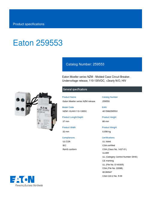
Eaton 259553Eaton Moeller series NZM - Molded Case Circuit Breaker.Undervoltage release, 110-130VDC, +2early N/O, HIVGeneral specificationsEaton Moeller series NZM release259553NZM1-XUHIV110-130DC401508259553137 mm66 mm32 mm0.056 kgUL/CSAIECRoHS conform UL listedCSA certifiedCSA (Class No. 1437-01)UL489UL (Category Control Number DIHS) CE markingUL (File No. E140305)CSA (File No. 22086)IEC60947CSA-C22.2 No. 5-09Product Name Catalog Number Model Code EANProduct Length/Depth Product Height Product Width Product Weight Compliances CertificationsIs the panel builder's responsibility. The specifications for the switchgear must be observed.0 VMeets the product standard's requirements.10 msIs the panel builder's responsibility. The specifications for the switchgear must be observed.Does not apply, since the entire switchgear needs to be evaluated.1.5 VAMeets the product standard's requirements.110 VTwo early-make auxiliary contacts0.8 W0 VIs the panel builder's responsibility.15 msUndervoltage release with 2 early-make auxiliary contacts, e.g., for early-make connection of undervoltage release in main switch applications, as well as for interlock and load shedding circuits. For use with emergency-stop devices in connection with an emergency-stop button. When the under-voltage trip is switched eaton-feerum-the-whole-grain-solution-success-story-en-us.pdf eaton-digital-nzm-brochure-br013003en-en-us.pdfeaton-digital-nzm-catalog-ca013003en-en-us.pdfDA-DC-03_NZM1eaton-circuit-breaker-release-nzm-mccb-dimensions.epseaton-circuit-breaker-undervoltage-nzm-mccb-3d-drawing-004.epsM1-XUHIV110-130DCIL01203002ZThe new digital NZM RangeIntroduction of the new digital circuit breaker NZMDA-CS-nzm1_xuDA-CD-nzm1_xueaton-nzm-technical-information-sheet10.11 Short-circuit ratingRated control supply voltage (Us) at AC, 50 Hz - min 10.4 Clearances and creepage distancesMinimum command time - min10.12 Electromagnetic compatibility10.2.5 LiftingPick-up power consumption at AC (undervoltage release) 10.2.3.1 Verification of thermal stability of enclosures Rated control supply voltage (Us) at DC - minFitted with:Pick-up power consumption at DC (undervoltage release) Rated control supply voltage (Us) at AC, 50 Hz - max 10.8 Connections for external conductorsMinimum command time - maxSpecial features BrochuresCatalogs Certification reports DrawingseCAD model Installation instructions Installation videos mCAD model Technical data sheetsoff, accidental contact with the circuit breaker’s primary contacts is prevented when switched on. Early make of auxiliary contacts on switching on and off (manual operation): approx. 20 ms Undervoltage releases cannot be installed simultaneously with NZM...-XHIV... early-make auxiliary contact or NZM...-XA... shunt release.Rated control supply voltage (Us) at DC - max130 V10.9.3 Impulse withstand voltageIs the panel builder's responsibility.Rated control supply voltage110 - 130 V DC10.6 Incorporation of switching devices and componentsDoes not apply, since the entire switchgear needs to be evaluated.10.5 Protection against electric shockDoes not apply, since the entire switchgear needs to be evaluated.Used withNZM1(-4), N(S)1(-4)Electric connection typeScrew connection10.13 Mechanical functionThe device meets the requirements, provided the information in the instruction leaflet (IL) is observed.10.2.6 Mechanical impactDoes not apply, since the entire switchgear needs to be evaluated.10.9.4 Testing of enclosures made of insulating materialIs the panel builder's responsibility.Number of contacts (normally closed contacts)10.3 Degree of protection of assembliesDoes not apply, since the entire switchgear needs to be evaluated.Voltage typeDCDrop-out voltage of undervoltage release AC/DC - min0.35 x UsFrameNZM1Reaction time19 msSuitable forOff-load switchVoltage tolerance - min.85Rated control voltage (relay contacts)130 V DC110 V DCPower consumption0.8 W (sealing DC)1.5 VA (sealing AC)10.2.3.2 Verification of resistance of insulating materials to normal heatMeets the product standard's requirements.Drop-out voltage of undervoltage release AC/DC - max0.7 x Us10.2.3.3 Resist. of insul. mat. to abnormal heat/fire by internal elect. effectsMeets the product standard's requirements.Connection typeWith terminal block on the left-hand switch side10.9.2 Power-frequency electric strengthIs the panel builder's responsibility.Voltage tolerance - max1.1Undelayed short-circuit release - min0 ARated control supply voltage (Us) at AC, 60 Hz - min0 V10.7 Internal electrical circuits and connectionsIs the panel builder's responsibility.Terminal capacity (solid/flexible conductor)0.75 mm² - 2.5 mm² (1x) for undervoltage releases, off-delayed with ferrule0.75 mm² - 2.5 mm² (2x) at shunt release with ferrule18 - 14 AWG (2x) at shunt releaseEaton Corporation plc Eaton House30 Pembroke Road Dublin 4, Ireland © 2023 Eaton. All Rights Reserved. Eaton is a registered trademark.All other trademarks areproperty of their respectiveowners./socialmedia0.75 mm² - 2.5 mm² (2x) for undervoltage releases, off-delayed with ferrule18 - 14 AWG (1x) at shunt release18 - 14 AWG (1x) for undervoltage releases, off-delayed 0.75 mm² - 2.5 mm² (1x) at shunt release with ferrule 18 - 14 AWG (2x) for undervoltage releases, off-delayed The panel builder is responsible for the temperature rise calculation. Eaton will provide heat dissipation data for the devices.Accessory Undervoltage release Undervoltage release with early-make auxiliary contact Meets the product standard's requirements.Meets the product standard's requirements.Meets the product standard's requirements.0 V20 A10.10 Temperature riseType10.2.2 Corrosion resistance10.2.4 Resistance to ultra-violet (UV) radiation 10.2.7 InscriptionsRated control supply voltage (Us) at AC, 60 Hz - max Number of contacts (normally open contacts)Undelayed short-circuit release - max Number of contacts (change-over contacts)。
Eaton EGH3030FFG 系列G型筋膜封闭电路保护器产品说明说明书
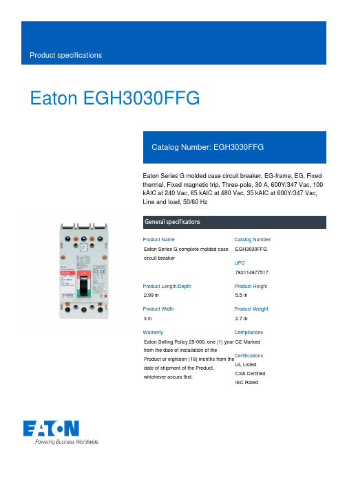
Eaton EGH3030FFGEaton Series G molded case circuit breaker, EG-frame, EG, Fixed thermal, Fixed magnetic trip, Three-pole, 30 A, 600Y/347 Vac, 100 kAIC at 240 Vac, 65 kAIC at 480 Vac, 35 kAIC at 600Y/347 Vac, Line and load, 50/60 HzGeneral specificationsEaton Series G complete molded case circuit breakerEGH3030FFG 7821148775172.99 in 5.5 in3 in 2.7 lb Eaton Selling Policy 25-000, one (1) year from the date of installation of theProduct or eighteen (18) months from thedate of shipment of the Product,whichever occurs first.CE Marked UL ListedCSA CertifiedIEC RatedProduct NameCatalog Number UPCProduct Length/Depth Product Height Product Width Product Weight WarrantyCompliancesCertificationsSeries G35 kAIC at 600Y/347 Vac65 kAIC at 480 Vac100 kAIC at 240 Vac Complete breakerEGEG50/60 HzComplete breakerLine and load600Y/347 Vac30 AFixed thermal, fixed magnetic Three-pole Application of Multi-Wire Terminals for Molded Case Circuit Breakers Application of Tap Rules to Molded Case Breaker TerminalsHigh performance operating handles for Series G circuit breakers product aidPlug-in adapters for molded case circuit breakers product aidMolded case circuit breakers providing higher levels of selective coordination product aidComprehensive circuit protection for control panel applicationsPower metering and monitoring with Modbus RTU product aidMulti-wire lugs product aidCurrent limiting molded case circuit breaker module product aidCircuit breaker motor operators product aidStrandAble terminals product aidSeries G MCCB quick selectorCurrent limiting molded case circuit breaker module for series G, JG and CLSeries G Molded Case Circuit Breakers - Quick SelectorMotor protection circuit breakers product aidBreaker service centersMolded case circuit breakers catalogEaton's Volume 4—Circuit ProtectionMOEM MCCB product selection guideNG and ND-Frame molded case circuit breakersEaton Specification Sheet - EGH3030FFGSeriesInterrupt ratingTypeFrameCircuit breaker type Frequency ratingCircuit breaker frame type TerminalsVoltage rating Amperage RatingTrip TypeNumber of poles Application notesBrochuresCatalogsSpecifications and datasheetsEaton Corporation plc Eaton House30 Pembroke Road Dublin 4, Ireland © 2023 Eaton. All Rights Reserved. Eaton is a registered trademark.All other trademarks areproperty of their respectiveowners./socialmedia。
美国Eaton公司产品说明书:Eaton Moeller系列PKZM01电机保护电路断路器
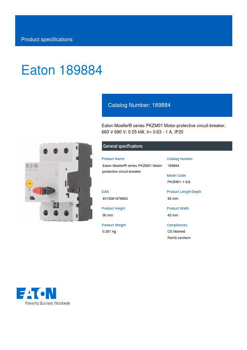
Eaton 189884Eaton Moeller® series PKZM01 Motor-protective circuit-breaker, 660 V 690 V: 0.55 kW, Ir= 0.63 - 1 A, IP20General specificationsEaton Moeller® series PKZM01 Motor-protective circuit-breaker189884PKZM01-1-EA401508187880293 mm 90 mm 45 mm 0.261 kgCE Marked RoHS conformProduct NameCatalog Number Model Code EANProduct Length/Depth Product Height Product Width Product Weight CompliancesPush buttonPhase failure sensitive Three-pole 0.12 kW 0.25 kW 690 V 690 V 1 A0.63 A1 A Motor Starters in System xStart - brochureSave time and space thanks to the new link module PKZM0-XDM32MESwitching and protecting motors - catalogProduct Range Catalog Switching and protecting motorseaton-manual-motor-starters-characteristic-characteristic-curve-008.eps eaton-manual-motor-starters-characteristic-characteristic-curve-009.eps eaton-manual-motor-starters-characteristic-characteristic-curve-005.epsDA-DC-00004883.pdfeaton-manual-motor-starters-circuit-breaker-pkzm01-dimensions.eps eaton-manual-motor-starters-circuit-breaker-pkzm01-3d-drawing-002.epseaton-general-ie-ready-dilm-contactor-standards.epseaton-manual-motor-starters-mounting-3d-drawing-002.epsDA-CE-ETN.PKZM01-1-EAIL034045ZUActuator type Functions Number of poles Rated operational power at AC-3, 220/230 V, 50 Hz Rated operational power at AC-3, 380/400 V, 50 Hz Rated operational voltage (Ue) - minRated operational voltage (Ue) - maxRated uninterrupted current (Iu)Overload release current setting - minOverload release current setting - maxBrochuresCataloguesCharacteristic curveDeclarations of conformityDrawingseCAD modelInstallation instructionsInstallation videosEaton Corporation plc Eaton House30 Pembroke Road Dublin 4, Ireland © 2023 Eaton. All rights reserved. Eaton is a registered trademark.All other trademarks areproperty of their respectiveowners./socialmediaWIN-WIN with push-in technologyDA-CD-pkzm01DA-CS-pkzm01mCAD model。
- 1、下载文档前请自行甄别文档内容的完整性,平台不提供额外的编辑、内容补充、找答案等附加服务。
- 2、"仅部分预览"的文档,不可在线预览部分如存在完整性等问题,可反馈申请退款(可完整预览的文档不适用该条件!)。
- 3、如文档侵犯您的权益,请联系客服反馈,我们会尽快为您处理(人工客服工作时间:9:00-18:30)。
ᤣԪ٧ ࠆਖ਼᠆ܫᣑ ึ
ACܫ Мၸ̀ᛪ
ᣤႂᎩ
HMDL 1000V直流塑壳断路器有 一个完整的配件补充,提供合闸 指示,能够远程脱扣,根据现场 要求进行配置。HMDL 1000V直 流塑壳断路器内置符合CCC标 准及UL认证489标准的塑壳断路 器。
可用的附件
• 端子 • 锁定装置 • 端盖包 • 旋转手柄机制 • 软轴手柄机制 • 报警锁 • 辅助开关 • 分励脱扣 • 欠压脱扣 • 电动操作机构
Юᦉᬃ͇
ᬃ͇ྫྷՁ
ԾΞ߶ᜈ ᣘүᝎཁ 1A-1B 2A-2B ઐᝎཁ 1 make/1 break ᣘүԢઐᝎཁ 1A-1B, 1 make/1 break ࢺΞ߶ᜈ ѫҴᑱ੭ 12 Vdc 24 Vdc 48 Vdc
A1X4PK A2X4PK A1L4RPK AA114RPK
SNT4LP03K SNT4LP03K SNT4LP23K SNT4LP23K SNT4LP26K SNT4LP14K SNT4LP11K UVH4LP20K UVH4LP21K UVH4LP22K UVH4LP26K UVH4LP28K UVH4LP08K
16.00 (406.4)
ࡆࠩ(mm)
).%-7ᄯึ
శஜ
ܦ ଠᤗ HMDL
ᮨ߿ԟஜ ஜ ႂึᄉᔴډ ణܷᮨ߿ႂԌ 1000 VdcௐᄉѫறᑞҦ ۲эຝऎ ኃʻழᝢ ௦ՠၸ̅ʽᤈጲ ቪߔ ᨷ/ᨶጲ ᨶጲ
3 300–800A 1000 Vdc 7.5 kA 50°C UL 489, CCC Ժ̾ (3) 3/0–400 kcmil (3) 3/0–300 kcmil
专为光伏发电装置的高温和低温 需求设计而成,HMDL 1000V直 流塑壳断路器经受极端环境的循 环测试,并承载一个强大的工作 温度范围。 50 ℃的温度环境中 , 脱扣单元在 100% 的铭牌电流下 进行校验 , 这确保了断路器能在 太阳能典型环境的较高的温度下 连续运行。 严格的第三方测试包括有限和标 准的故障电流测试,电气和机械 寿命,绝缘体耐电压以及温度测 试。断路器各极必须串联操作。
HMDL 1000V直流塑壳断路器 主要应用于光伏行业
把太阳能转化成电能
光伏(PV)系统把太阳光能转换成电能,直接送入 电网。在系统内,直流断路器的作用是为连接光伏模 块和组合器或逆变器的线路提供断路保护。
伊顿公司是全球领先的电路保 护产品供应商。我们把这一行 业专长带到光伏市场,提供一 系列结合开断和电路保护功能 的产品用以保护和监测光伏发 电系统,HMDL 1000V直流塑壳 断路器正是其中一员。HMDL断 路器可以代替组合箱及逆变应用 中的保险丝和隔离开关,节省空 间,简化采购流程,并降低配件 需求。HMDL断路器也可用于保 护,切换和隔离商业和公用 250 Vdc 120 Vac Ԍᑱ੭ 12 Vdc 24 Vdc 48 Vdc 125 Vdc 250 Vdc 120 Vac
HMDLDC3800W
HMDL 1000Vᄯึܦ܇றᡸ٧
40°Cௐ ᮨ߿ႂึ 300 350 400 450 500 600 700 800 றᡸ٧ ྫྷՁᆉ HMDLDC3800W HMDLDC3800W HMDLDC3800W HMDLDC3800W HMDLDC3800W HMDLDC3800W HMDLDC3800W HMDLDC3800W ಕэቪߔ ྫྷՁᆉ TA700MA1 TA700MA1 TA700MA1 TA700MA1 TA700MA1 TA700MA1 TA700MA1 TA800MA2
8.25 (209.6) ґڎ
4.06 (103.1) Ξڎ
伊顿集团 亚太总部 上海市长宁区临虹路280弄3号 邮编: 200335 电话: 86-21-52000099 传真: 86-21-52000200 © 2014 伊顿公司 保留所有权利 中国印刷 2014年1月
伊顿是伊顿公司的注册商标。 所有商标为各自所有人所有。
特点
• 专为满足更高电压和较低的故 障电流水平的太阳能系统 • 可以应用在接地或不接地系统 • 宽泛的额定电流值为进线串的 匹配增加了可选性 • 从-40°C到+90ºC的极端周围 环境下,通过了严格的测试 • 全配套的附件用于检测状态, 发信号和锁定/标记 • 消除保险丝储存成本和匹配 问题 • 符合UL 489标准及CCC标准
ᝠ᠓ζো
HMDLDC 3 800 W
ۋՁ Series C HMDLDC----ᄯึ-M(800 max) HMDL----ஜ 3 =3 ࡊಕ ᮨ߿ႂึ 300 = 300A 350 = 350A 400 = 400A 450 = 450A 500 = 500A 600 = 600A 700 = 700A 800 = 800A W = ʿӉդቪߔ