Sample and Hold 模拟集成电路设计
模拟集成电路的设计流程

模拟集成电路的设计流程一、需求分析与规格确定1. 应用场景:了解电路将用于何种设备,如手机、电脑、汽车电子等,以及这些设备对电路的特殊要求。
2. 性能指标:根据应用场景,确定电路的关键性能参数,如增益、带宽、功耗、线性度、噪声等。
3. 工作条件:明确电路的工作电压、温度范围、湿度、震动等环境条件。
4. 成本与尺寸:考虑电路的成本目标和封装尺寸,确保设计在商业上是可行的。
5. 制定规格书:将上述分析结果整理成详细的技术规格书,为后续设计工作提供依据。
二、电路架构设计与仿真在规格确定后,设计师开始进行电路架构的设计。
这一阶段,设计师需要运用专业知识,选择合适的电路拓扑,并进行初步的仿真验证。
1. 电路拓扑选择:根据规格书要求,选择合适的电路拓扑,如运算放大器、滤波器、稳压器等。
2. 元器件选型:根据电路拓扑,选取合适的晶体管、电阻、电容等元器件。
3. 原理图绘制:使用电路设计软件,绘制电路的原理图。
4. 参数调整与优化:通过仿真软件,对电路参数进行调整,以优化电路性能。
5. 仿真验证:进行直流分析、交流分析、瞬态分析等仿真,验证电路在不同工作条件下的性能是否符合规格要求。
三、版图布局与设计规则检查1. 版图绘制:根据原理图,绘制电路的版图,包括元器件布局、连线、焊盘等。
2. 设计规则检查(DRC):确保版图设计符合制造工艺的设计规则,如线宽、线间距、寄生效应等。
3. 版图与原理图一致性检查(LVS):通过软件工具,比较版图与原理图是否一致,确保没有设计错误。
4. 参数提取:从版图中提取寄生参数,为后续的版图后仿真做准备。
四、版图后仿真与优化版图设计完成后,需要进行版图后仿真,以验证实际制造出的电路性能。
1. 版图后仿真:利用提取的寄生参数,对版图进行后仿真,检查电路性能是否受到影响。
2. 性能优化:根据仿真结果,对版图进行必要的调整,以优化电路性能。
3. 设计迭代:如果仿真结果不理想,可能需要返回前面的步骤,对电路架构或版图进行重新设计。
集成电路EDA与验证技术课件:模拟集成电路设计与仿真
模拟集成电路设计与仿真
常用命令格式: (1) DEFINE 格式:DEFINE <库名> <库路径> 例: DEFINE sample /export/cadence/IC615USER5/tools.lnx86/dfII/samples/cdslib/sa mple (2) INCLUDE 格式:INCLUDE <另外一个cds.lib 的全路径>
模拟集成电路设计与仿真
图3.2 Spectre中包含的各种仿真器
模拟集成电路设计与仿真
2.精确的晶体管模型 Spectre为所有的仿真器提供一致的器件模型,这有利于 消除不同模型间的相关性,从而得到快速收敛的仿真结果。 模型的一致性也保证了器件模型在升级时可以同时应用于所 有的仿真器。 3.高效的程序语言和网表支持 Spectre仿真平台支持多种设计提取方法,并兼容绝大多 数SPICE输入平台。Spectre可以读取Spectre、SPICE以及 Verilog-A格式的器件模型,并支持标准的Verilog-AMS、 VHDL-AMS、Verilog-A、Verilog以及VHDL格式的文本输 入。
模拟集成电路设计与仿真
5.有力衔接了版图设计平台 对于完整的版图设计平台而言,Spectre是不可或缺的重 要环节,它能方便地利用提取的寄生元件参数来快速完成后 仿真(post-layout simulation)的模拟,并与前仿真(pre-layout simulation)的模拟结果作比较,紧密的连接了电路 (Schematic)和版图(layout)的设计。 6.交互的仿真模式 设计者可以在仿真过程中快速改变参数,并在不断调整 参数和模拟之中找到最佳的电路设计结果,减少电路设计者 模拟所花费的时间。
模拟集成电路设计原理实验指导书
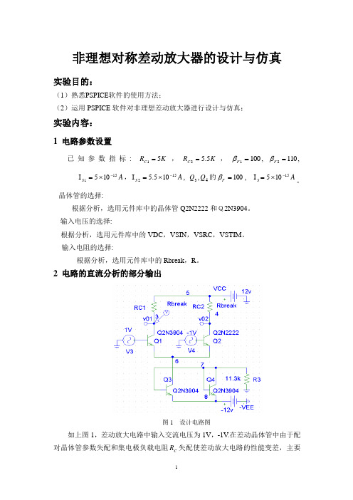
非理想对称差动放大器的设计与仿真 实验目的:(1)熟悉PSPICE 软件的使用方法;(2)运用PSPICE 软件对非理想差动放大器进行设计与仿真;实验内容:1 电路参数设置已知参数指标: K R C 51=,K R C 5.52=,,1001=F β,1102=F βA S 151105-⨯=I ,A S 152105.5-⨯=I , 3Q ,4Q 的100=F β, I A S 15105-⨯=。
晶体管的选择:根据分析,选用元件库中的晶体管Q2N2222和Q2N3904。
输入电压的选择:根据分析,选用元件库中的VDC ,VSIN ,VSRC ,VSTIM 。
输入电阻的选择:根据分析,选用元件库中的Rbreak ,R 。
2 电路的直流分析的部分输出图1 设计电路图如上图1,差动放大电路中输入交流电压为1V ,-1V .在差动晶体管中由于配对晶体管参数失配和集电极负载电阻C R 失配使差动放大电路的性能变差,主要表现为:当输入加差模信号时输出会产生共模分量,当输入加共模信号时会产生差模分量.如果下一级也是差动放大电路,这种差模输入-共模输出或共模输入-差模输出的转换对整个放大电路的性能将产生十分不利的影响。
以下通过电路来分析讨论这一问题。
图2 差分放大电路直流工作点各个晶体管直流工作点见附录2,其上半部分为三极管的直流偏置情况。
IC 行列出了四个晶体管的工作电流分别为10.405CQ I MA =,20.444CQ I MA =, 30.861CQ I MA =,40.983CQ I MA =。
而IB,VBE,VBCVCE 为三极管的其他直流工作点参数。
图3 直流传输特性图3是当输入信号V1由0.125+变化时,输出电压V01和V02的变--0.125化曲线。
利用直流扫描分析可以清楚地看到直流传输特性,为分析电路直流工作状态提供方便。
3 交流小信号分析图4 差模输出曲线如上图为输入差模信号时输出电压曲线。
模拟集成电路设计教学大纲

模拟集成电路设计教学大纲目录一、课程开设目的和要求2二、教学中应注意的问题2三、课程内容及学时分配2第一章模拟电路设计绪论2第二章MOS器件物理基础2第三章单级放大器3第四章差动放大器3第五章无源与有源电流镜3第六章放大器的频率特性3第八章反馈3第九章运算放大器3高级专题3四、授课学时分配4五、实践环节安排4六、教材及参考书目5课程名称:模拟集成电路设计课程编号:055515英文名称:Analog IC design课程性质:独立设课课程属性:专业限选课应开学期:第5学期学时学分:课程总学时___48,其中实验学时一-一8。
课程总学分--3学生类别:本科生适用专业:电子科学与技术专业的学生。
先修课程:电路、模拟电子技术、半导体物理、固体物理、集成电路版图设计等课程。
一、教学目的和要求CMOS模拟集成电路设计课程是电子科学与技术专业(微电子方向)的主干课程,在教学过程中可以培养学生对在先修课程中所学到的有关知识和技能的综合运用能力和CMOS模拟集成电路分析、设计能力,掌握微电子技术人员所需的基本理论和技能,为学生进一步学习硕士有关专业课程和日后从事集成电路设计工作打下基础。
二、教学中应注意的问题1、教学过程中应强调基本概念的理解,着重注意引导和培养学生的电路分析能力和设计能力2、注重使用集成电路设计工具对电路进行分析仿真设计的训练。
3、重视学生的计算能力培养。
三、教学内容第一章模拟电路设计绪论本课程讨论模拟CMOS集成电路的分析与设计,既着重基本原理,也着重于学生需要掌握的现代工业中新的范例。
掌握研究模拟电路的重要性、研究模拟集成电路以及CMOS模拟集成电路的重要性,掌握电路设计的一般概念。
第二章MOS器件物理基础重点与难点:重点在于MOS的I/V特性以及二级效应。
难点在于小信号模型和SPICE模型。
掌握MOSFET的符号和结构,MOS的I/V特性以及二级效应,掌握MOS 器件的版图、电容、小信号模型和SPICE模型,会用这些模型分析MOS电路。
模拟集成电路设计书籍
模拟集成电路设计书籍模拟集成电路设计是电子工程领域中重要的一部分,它涉及了电路设计的各个方面,包括电路原理、电路分析、电路优化等。
模拟集成电路设计书籍是电子工程师学习和掌握模拟集成电路设计知识的重要工具。
本文将介绍几本经典的模拟集成电路设计书籍,供读者参考和学习。
一、《模拟集成电路设计》(作者:王晓斌)本书是一本介绍模拟集成电路设计基础知识和方法的入门书籍。
它以通俗易懂的语言,系统地介绍了模拟集成电路的基本概念、模拟电路设计的基本原理和方法。
通过本书的学习,读者可以了解模拟集成电路的基本工作原理,掌握常见的模拟电路设计方法,提高模拟电路设计的能力。
二、《模拟集成电路设计与仿真》(作者:叶文忠)本书是一本介绍模拟集成电路设计和仿真的综合性教材。
它详细介绍了模拟集成电路的设计流程、电路分析方法、放大电路的设计和布局等内容。
同时,本书还介绍了常用的模拟电路仿真工具,如SPICE和Cadence等,帮助读者掌握模拟电路的仿真技术。
三、《模拟集成电路设计实战指南》(作者:张志刚)本书是一本介绍模拟集成电路设计实战经验和技巧的实用指南。
它结合作者多年的实际经验,从设计思路、电路选型、性能指标等方面,详细介绍了模拟集成电路设计的实战技巧。
本书内容丰富,实例丰富,适合作为模拟电路设计工程师的参考书。
四、《模拟集成电路设计与布局》(作者:李强)本书是一本介绍模拟集成电路设计和布局的综合性教材。
它系统地介绍了模拟集成电路设计和布局的基本原理和方法,包括电路设计流程、电路分析方法、电路布局和布线等内容。
本书通过丰富的实例和案例,帮助读者深入理解模拟电路设计和布局的关键技术。
五、《集成电路设计基础》(作者:陈坚)本书是一本介绍集成电路设计基础知识的教材。
它包括模拟电路设计基础、数字电路设计基础和混合信号电路设计基础等内容。
本书内容全面,结构严谨,适合作为集成电路设计初学者的入门书籍。
以上是几本经典的模拟集成电路设计书籍的简要介绍。
《模拟集成电路设计》教学大纲

《模拟集成电路设计》课程教学大纲一、课程基本信息1、课程编码:2、课程名称(中/英文):模拟集成电路设计/ Design of Analog integrated Circuits3、学时/学分:56学时/3.5学分4、先修课程:电路基础、信号与系统、半导体物理与器件、微电子制造工艺5、开课单位:微电子学院6、开课学期(春/秋/春、秋):秋7、课程类别:专业核心课程8、课程简介(中/英文):本课程为微电子专业的必修课,专业核心课程,是集成电路设计方向最核心的专业课程之一。
本课程主要介绍典型模拟CMOS集成电路的工作原理、设计方法和设计流程、仿真分析方法,以及模拟CMOS集成电路的最新研发动态。
通过该课程的学习,将为学生今后从事集成电路设计奠定坚实的理论基础。
9、教材及教学参考书:教材:《模拟集成电路设计》,魏廷存,等编著教学参考书:1)《模拟CMOS集成电路设计》(第2版).2)《CMOS模拟集成电路设计》二、课程教学目标本课程为微电子专业的必修课,专业核心课程,是集成电路设计方向最核心的专业课程之一。
通过该课程的学习,将为学生今后从事集成电路设计奠定坚实的理论基础。
本课程主要介绍典型模拟CMOS集成电路的工作原理、设计方法和设计流程、仿真分析方法,以及模拟CMOS模拟集成电路的最新研发动态。
主要内容有:1)模拟CMOS集成电路的发展历史及趋势、功能及应用领域、设计流程以及仿真分析方法;2)CMOS元器件的工作原理及其各种等效数学模型(低频、高频、噪声等);3)针对典型模拟电路模块,包括电流镜、各种单级放大器、运算放大器、比较器、基准电压与电流产生电路、时钟信号产生电路、ADC与DAC电路等,重点介绍其工作原理、性能分析(直流/交流/瞬态/噪声/鲁棒性等特性分析)和仿真方法以及电路设计方法;4)介绍模拟CMOS集成电路设计领域的最新研究成果,包括低功耗、低噪声、低电压模拟CMOS集成电路设计技术。
模拟集成电路设计经典教材
1、 CMOS analog circuit design by P .E.ALLEN评定:理论性 90 实用性 70 编写100精彩内容:运放的设计流程、比较器、开关电容这本书在国内非常流行, 中文版也翻译的很好, 是很多人的入门教材。
建议大家读影印版, 因为 ic 领域的绝大部分文献是以英文写成的。
如果你只能读中文版,你的学习资料将非常有限。
笔者对这本书的评价并不高,认为该书理论有余,认为该书理论有余,实用性实用性不足,在内容的安排上也有不妥的地方,比如没有安排专门的章节讲述反馈, 在小信号的计算方面也没有巧方法。
本书最精彩的部分应该就是运放的设计流程了。
这是领域里非常重要的问题,像 Allen 教授这样将设计流程一步一步表述出来在其他书里 是没有的。
这正体现了 Allen 教授的治学风格:苛求理论的完整性系统性。
但是,作为一项工程技术,最关键的是要解决问题,是能够拿 出一套实用的经济的保险的方案。
所以,读者会发现,看完最后一章关于 ADC/DAC 的内容,似乎是面面俱到,几种结构的 ADC 都提到 了,但是当读者想要根据需求选择并设计一种 ADC/DAC 时,却无从下手。
书中关于比较器的内容也很精彩,器的内容也很精彩,也体现了也体现了 Allen 教授求全的风格。
教授求全的风格。
不过,不过,正好其它教科书里对比较器的系统讲述较少,该书正好弥补了 这一缺陷。
Allen 教授是开关电容电路和滤波器电路的专家。
书中的相关章节很适合作为开关电容电路的入门教材。
该书的排版、图表等书籍编写方面的工作也做的很好。
像 Allen 这样的理论派教授不管在那所大学里,大概都会很快的获得晋升吧。
另外, Allen 教授的学生 Rincon Moca 教授写的关于 LDO 的书非常详尽,值得一读。
2、 CMOS Circuit Design Layout and Simulation CMOS Mixed-Signal Circuit Design byR.J.Baker评定:理论性 80 实用性 100 编写 80精彩内容:数据转换器的建模和测量、hspice网表 这本书的风格和 Allen 的书刚好相反:理论的系统性不强,但是极为实用,甚至给出大量的电路仿真网表和 hspice 仿真图线。
模拟集成电路设计

模拟集成电路设计模拟集成电路设计是指将电子元件和电路设计应用于模拟信号的电子设计技术。
相比数字电路设计,模拟集成电路设计非常复杂,因为它以复杂的方式处理模拟信号,并且有大量的设计和实现参数,例如电源电压、输入信号电平、输出信号电平和传输函数,等等。
模拟集成电路设计的发展形式改变了电子元件与电路设计应用的历史。
模拟集成电路设计自从20世纪60年代起就开始了,有一些电子元件模型和电路技术已经形成。
此后,各种电子元件和电路技术又不断发展,使得现代模拟集成电路设计技术获得了跨越性的发展。
模拟集成电路设计通常包括多种电子元件和电路技术,例如放大器、滤波器、衰减器、可调电容器、电阻器、电感器、二极管、直流电源等。
模拟集成电路设计中的多种元件和电路技术十分复杂,需要有很强的电子技术和理论基础。
模拟集成电路设计的主要目的是实现对模拟信号进行处理,并将输入信号转换成输出信号,使信号得到有效处理。
这种设计可以解决复杂的信号处理问题,例如模拟音频信号处理、数字音频处理、数字图像处理、生物医学信号处理等。
模拟集成电路设计的常用设计工具可以分为两类,即硬件设计工具和软件设计工具。
硬件设计工具包括电路板布线工具、仿真工具和示波器等,它们用于评估电路组件的正确性和性能,并实现电路原理图设计。
软件设计工具包括模拟电路模拟器、状态器件仿真器和模拟示波器等,他们可以进行精细的模拟电路设计和分析。
综上所述,模拟集成电路设计的发展为电子元件与电路设计应用带来了极大的发展,为电子界的设计提供了有效的技术支持。
模拟集成电路设计技术仍然在不断发展,届时电子元件与电路设计应用能力将会进一步提升,可以更好地适应不断变化的电子应用环境。
现代模拟集成电路设计

《现代模拟集成电路设计》是2024年清华大学出版社出版的图书,作者是孙楠、刘佳欣、揭路。
本书围绕先进工艺节点,基于跨导效率的设计方法介绍现代模拟集成电路的分析与设计方法。
全书大体上分为三部分: 第一部分(第1~7章)对模拟集成电路中的基本元件晶体管,以及基本的分析与设计方法进行介绍,包括晶体管的长沟道模型与小信号模型、晶体管的基本电路结构、晶体管的性能指标、基于跨导效率的模拟电路设计方法、模拟电路的带宽分析方法、模拟电路中的噪声等。
第二部分(第8~10章)介绍模拟电路设计中常见的一些问题与设计技巧,如器件偏差、差分结构、负反馈技术等,并引入模拟电路中最常见的电路结构,即运算放大器与开关电容电路。
第三部分(第11~14章)详细介绍了运算放大器的分析与设计方法,并提供完整的运算放大器设计实例作为参考。
此外,第15章和第16章还介绍了基准源电路以及集成电路的工艺演进。
analysis and design of analog integrated中文版
analysis and design of analog integrated中文版分析和设计模拟集成电路是电子工程领域中的重要课题。
模拟集成电路是指电子设备中用于处理连续信号的电路,它在许多应用中起着至关重要的作用,包括音频信号处理、通信系统以及传感器接口等等。
本文将从分析和设计的角度,详细介绍模拟集成电路的原理、方法和流程。
希望能够帮助读者对模拟集成电路的工作原理和设计步骤有更深入的理解。
第一部分:模拟集成电路的基本原理首先,我们需要了解模拟集成电路的基本原理。
模拟集成电路是使用电荷、电流或电压来表示和处理连续信号的电路。
在模拟集成电路中,我们通常使用模拟电子元件(比如电容、电感和电阻)和可控元件(如晶体管和运算放大器)来实现信号放大、滤波、混频等功能。
通过这些基本的电子元件和电路,我们可以将物理世界中的连续信号转换为可处理的电压、电流或电荷形式,从而实现我们所需的功能。
第二部分:模拟集成电路的设计方法设计模拟集成电路需要详细的方法和流程。
首先,我们需要明确设计的目标和要求。
例如,我们需要设计一个低噪声放大器或一个高精度滤波器。
然后,我们需要根据目标和要求选择适当的电路拓扑结构。
常见的电路拓扑结构包括共射极放大器、共基极放大器、共集极放大器等等。
我们可以根据具体应用的要求选择不同的电路拓扑结构。
在选择了电路拓扑结构之后,接下来是选择合适的电子元件。
电子元件的选择需要考虑导通电阻、电流增益和频率响应等参数。
常见的电子元件包括电容、电感、晶体管和操作放大器等。
在选择电子元件时,需要平衡性能和成本,同时保证设计的可行性。
在选择了电路拓扑结构和电子元件之后,我们需要进行电路的分析和仿真。
使用电路分析软件,我们可以对电路进行直流和交流的分析,以验证电路的性能。
通过仿真,我们可以获得电路的频率响应、增益和相位等信息。
通过仿真结果,我们可以对电路进行优化。
根据优化的结果,我们可能需要调整电路的拓扑结构、电子元件的参数或者引入补偿电路。
一种100MHz采样频率CMOS采样_保持电路
Abstract: T he fundamenta l theor y of the sample and hold circuit is analyzed. A fully differential CM OS sample-
and- hold amplif ier ( SH A ) is desig ned using a gain- boo st er cir cuit, for which a sampling rate of 100 M H z has been achiev ed. T he circuit is simulated and analyzed, tog ether with it s blo cks, based on Char ter s 0. 35 m standard CM O S process.
间, 使运放能够稳定地工作, 要求自举运放的单位增 益频率 3 满足 2 < 3 < 5 的条件( 其中, 5 是整个 运放的第二极点) 。为了满足设计要求, 在半个时间 周期( 5 ns) 之内完全建立, 需要对自举运放进行电 容补偿, 使其带宽满足上述要求, 从而消除由自举运 放引入的零点和极点问题。
92
谭 等: 一种 100 M H z 采样频 率 CM OS 采样/ 保持电路
2006 年
图 2 自举电路中采样开关的栅源电压
4 套筒式增益增强运算放大器的设计
采样保持电路中的核心部件是运算放大器, 其 性能直接决定了采样保持电路是否可以实现功能。 运算放大器的整体电路如图 3 所示。
度和输入输出电压的指标要求。对于自举运放, 并 不需要很高的增益, 但是希望得到较大的动态范围。 在设计的过程中, 要考虑自举运放和整体运放直接 带宽的相互关系[ 4] 。
《模拟集成电路设计》实验指导

尺寸 W/L
2um/0.7um=2.86 0.35um/2um=0.175 1um/0.7um=1.43 1um/1.4um=0.71
4、增益 AV 的估算
1 W AV g m1 ro1 / / ro3 2nCox I1 398 52dB ,符合要求。 L 1 n p I1
5、转换速率 Sr 的估算。 Sr=ISS/CL==1.2V/us 满足要求。 6、CMRR 的估算
CMRR ADM 1 1 W W g m3,4 (ro1,2 || ro3,4 )(1 2 g m1,2 RSS ) 2 pCox I3 (1 2 2nCox I 3 ) ACM L 3 n p I3 L 1 n I RSS
估算共模抑制比。 7、PSRR(电源抑制比)的估算 根据第 9 章 p275 对有源电流镜差动对的电源抑制比的计算和分析,电源抑制比的计算 公式为 PSRR gm1 ro1 / / ro3 。 8、输入共模电平和输出共模电平的确定。 根据题目要求,要求输入共模电平 Vin,CM=1.6V;Vout,CM=1.6V。 在以上的设计下,可以得到各个管子等的参数,从而确定电路参数的设计。 9、电路的总功率的估算。 电路的总功率为电压源和电流源的功率之和,即:
9、电路的总功率的估算。 电路的总功率为电压源和电流源的功率之和,即:
PD=PV+PI=VDD (ISS+IREF)-(VDD-VGS6) IREF
电压源的功率为:
Pv=VDD (ISS+IREF)=3.3V (6 3)A=29.7 W
电流源的功率为:
PI=-VI IREF=-(VDD-VGS6) IREF=-(3.3-0.9)V 3uA=-7.2uW
模拟集成电路教程教学设计

模拟集成电路教程教学设计简介模拟集成电路是电子工程中的一个重要概念。
学习模拟集成电路能够帮助学生深入理解电路的工作原理和实际应用场景。
本文将介绍一个教学设计,帮助教师在课堂中进行模拟集成电路教学。
教学目标•了解模拟电路的基本概念、性质以及主要特点•掌握常见的模拟电路的组成及其原理•能够使用基本工具分析和设计模拟电路教学内容第一部分:基本概念本部分将介绍模拟电路的基本概念,包括电路、信号、电源等等。
电路•简单电路的介绍•电路的元件、参数和符号•电压、电流、功率的定义和关系信号•信号的基本概念及表示•常见信号的波形、频率、幅度等参数的解释电源•直流电源和交流电源的概念和区别•电源的特性和参数第二部分:常见模拟电路的组成原理本部分将介绍常见模拟电路的组成原理,包括各种放大器、滤波器等等。
放大器•放大器的基本原理•常见的放大器分类及其特点•基本放大器电路设计滤波器•滤波器的基本原理•常见的滤波器分类及其特点•基本滤波器电路设计第三部分:模拟电路的分析和设计本部分将介绍模拟电路的分析和设计方法,包括常用的电路分析方法、SPICE 软件使用方法等。
电路分析•基本电路分析法和公式•节点法和电路分析法的对比及选择•电路分析的实例分析SPICE软件•SPICE软件的概念和特点•SPICE软件在模拟电路中的应用•SPICE软件的使用方法及实例分析教学方法•讲授:通过课堂讲授,介绍模拟电路的基本概念、常见模拟电路的组成原理、模拟电路的分析和设计方法等。
•实验:通过实验,帮助学生理解模拟电路的原理和应用。
•讨论:通过小组讨论,促进学生之间的交流和互动,提高学习效果。
教学评估学生在学习过程中,应该进行以下相关学习评估和测试:•课程设计作业和答辩:设计一个模拟电路,并进行分析和设计。
通过答辩,了解学生掌握模拟电路的能力。
•期末考试:考核学生对模拟电路的理解和应用能力。
考试内容涵盖模拟电路的基本概念、常见模拟电路的组成原理、模拟电路的分析和设计方法,实验考核等。
混合集成电路外文文献

A sample-and-hold circuit implemented with mixed MOS transistor channel length technique used in 16-bit 100-MS/s A/D converterTing Li*, Yuxin Wang, and Ruzhang LiNational Lab of Analog Integrated Circuits, Chongqing 400060, China* Email: tingtingsr@Abstract üThis paper discusses the design and implementation of a sample-and-hold circuit integrated into a high-speed and high-resolution A/D converter. In order to achieve the required speed and resolution, mixed MOS transistor channel length amplifier is used. The sample-and-hold circuit processes a differential 2.5-V p-p output signal swing and achieves 16-bit linearity with sampling frequency up to 100 MHz. Under these conditions, the total power consumption is 300 mW given by a single 3.3-V supply. The A/D converter is fabricated in a standard 0.35-m CMOS process technology, achieves 95.33-dBc spurious free dynamic range, 75.75-dBc signal-to-noise ratio for a 10.1-MHz input at -0.9dBFS at full sampling rate.KeywordsüSample-and-hold, Mixed channel length technique1.IntroductionThe increasing popularity of digital signal processing in high-frequency applications requires the development of high-performance A/D converters. In many A/D converters, a sample-and-hold (SH) circuit is required to hold the analog signal for a certain period of time so that the A/D converter can perform the conversion. In a high-speed and high-resolution A/D converter, a wide -band high-dc-gain sample-and-hold amplifier (SHA) is needed. By using a single MOS transistor channel length, it is difficult to implement wide-band and high-dc-gain without compromise.In this design, to overcome the above critical problem, a mixed MOS transistor channel length technique has been used in the implementation of the SHA in a SH circuit. The proposed SH circuit is applied to a 16-bit 100MS/s A/D converter in 0.35-m CMOS process.2.Sample-and-hold architectureTwo differential SH architectures were investigated. The first architecture, referred to as a charge-transferring SH, acquires the input signal on the input capacitors during the sample phase, and transfers only the differential charge to the feed-back capacitors during the hold phase. The second architecture is, referred to as a flip-around SH, acquires the input on the input capacitors during the sample phase, and flips the same capacitors to the output during the hold phase.The charge-transferring SH can handle a wide range of input signal common mode, has a flexible choose of SH gain and easy to get better SHA phase margin, but has larger capacitor induced noise and power consumption. The flip-around SH has lower capacitor induced noise and lower power consumption, but has worse input common-mode compliance and a fixed SH-gain of 1, and is hard to get better SHA phase margin.To achieving lower capacitor induced noise and proper SH gain for better SNR and SHA phase margin at the proper power consumption, a mixed architecture is usedas shown in Fig. 1.Figure 2. Schematic diagram of sample-and-hold circuitC s1 and C s2 acquire the input signal during the sample phase, and transfer only the differential charge to the feed-back capacitors of C f1 and C f2. C f1 and C f2 acquire the input signal in the sample phase, and flip to the output during the hold phase. If C s1 is equal to C s2, and if C f1 is equal to C f2, then the SH gain (C s1+C s2+C f1+C fs)/(C f1+C f2) will be equal to 1.25 when C f1 and C f2 are four times as large as that of C s1 and C s2 . The classic bootstrap circuit is employed to keep the V GSof the nMOS switching transistors M1, M2, M3 and M4 constant in the sample phase, and to keep the V GS of the nMOS switching transistors M5 and M6 constant in the hold phase.978-1-4244-5798-4/10/$26.00 ©2010 IEEE3.SHA design using mixed channel length technique The closed-loop structure of the sample-and-hold circuit requires a high-performance amplifier. On the one hand, the tradeoff between the close-loop-bandwidth and the dc-gain in the amplifier design results in a corresponding tradeoff between the speed response and the accuracy response in the hold phase; on the other hand, high-speed signals nonlinearity is minimized by having a large amplifier bandwidth and a linear gain. In this design, the large close-loop-bandwidth is preferred while the dc-gain has been chosen to satisfy 16-bit linearity in hold phase.The amplifier used in the sample-and-hold is shown in Fig. 2. It consist of two amplification stages: the first stage is an nMOS input differential pair based low-gain wide-band pre-amplifier to provide large common-mode compliance, the second stage is a telescopic amplifier which offers excellent dc-gain and bandwidth at differential 2.5-V p-p output signal swing. For a standard 0.35-m process technology, it is difficult to achieve large close-loop-bandwidth to satisfy 100MHz sampling rate and to achieve high dc-gain to satisfy 16-bit linearity simultaneously while processing a differential 2.5-V p-p output signal swing and driving more than 8pF load at3.3-V supply.Figure 2. Sample-and-hold amplifierIn this implementation, the telescopic stage has animproved dc-gain as well as a close-loop-bandwidth byusing a mixed MOS transistor channel length technique.Firstly, in order to enhance the dc-gain of the telescopicstage to satisfy 16-bit linearity in hold phase whileprocessing a differential 2.5-V p-p output signal swing anddriving more than 8pF load at 3.3V supply, in addition tothe employment of the gain-boosting circuit of thepMOS and nMOS cascode transistors, the cascodenMOS transistors, the pMOS transistors and thetransistors in the gain-boosting circuits use deliberately0.5-m channel length devices which have larger outputresistances than the 0.35-m channel length devices.Secondly, in order to get enough wideclosed-loop-bandwidth of the SHA, the input differentialpairs and the tail current sources of the two amplificationstages use 0.35-m channel length devices which havesmaller gate capacitance based on the sametransconductances or higher transconductances based onthe same device width than 0.5-m channel lengthdevices.Simulations show that the proposed amplifier achievesabout 65.8e phase margin, 100.5-dB dc gain, and730MHz close-loop-bandwidth while maintaining adifferential 2.5-V p-p output signal swing and drivingmore than 8pF load at 3.3-V supply.4.Experimental resultsThe sample-and-hold circuit mentioned above has beenused in a 16-bit 100MS/s A/D converter, and isprocessed in standard 0.35-m CMOS processtechnology. The micrograph of the fabricated chip isshown in Fig. 3. The sample-and-hold circuit area is0.58mm2and consumes 300mW of power.。
模拟集成电路设计
32
§3-5: 计算机仿真模型
四、几种模型跨导特性比较
第3章第6节
33
3.6 亚阈值电压区MOS模型 (特点:适合于亚阈区,即弱反型区)
§3-6:压阈值电压区MOS模型
34
亚阈值电压区MOS模型
(基于LEVEL3 模型)
指数律
平方律
VON VT fast
P79
§3-6:压阈值电压区MOS模型
en2
in2 gm2
8kT(1)
3gm
2
f
KF CoxWLK
'
f
(V 2 )
22
§3-3: 其他MOS管大信号模型的参数
三、噪声
1.均方噪声电流
2.等效输入均方电压噪声
en2
in2 gm2
8kT(1)
3gm
2
f
KF CoxWLK
'
f
(V 2 )
3.等效输入均方电压噪声简化表示
en2q
小的几何尺寸引起的二阶效应 P75
1.漏级电流
iDS
BETA vGS
VT
(1 fb 2
)vDE vDE
2.阈值电压
VT
Vbi
(
ETA 8.141022 Cox L3EFF
)vDS
GAMMA
fs (PHI vSB )1/2
fn (PHI vSB )
3.饱和电压
vsat
vgs VT 1 fb
g m
gds
g0
ID 1 VDS
ID
26
§3-4: MOS管的小信号模型
27
§3-4: MOS管的小信号模型 2.均方噪声电流
模拟集成电路设计与分析
模拟集成电路设计与分析随着科技的不断进步,集成电路在现代电子产品中扮演着至关重要的角色。
特别是模拟集成电路,它们被广泛应用于各种电子设备中,为我们提供了更多功能和便利。
本文将介绍模拟集成电路的设计与分析过程,帮助读者了解这个领域的基本原理和实践技巧。
一、模拟集成电路设计1. 模拟电路特点模拟电路是以连续的信号为基础,通过模拟元器件实现信号的放大、滤波、调节等功能。
与数字电路相比,模拟电路更注重信号的精确度和连续性。
2. 模拟集成电路概述模拟集成电路是将各种模拟元器件(如电阻、电容、二极管、晶体管等)集成在一个芯片上,以实现更高级的功能。
它可以减小电路的体积、降低功耗,并提高信号的稳定性和抗干扰能力。
3. 模拟集成电路设计流程(1)需求分析:了解客户需求,明确电路功能和性能要求。
(2)电路拓扑设计:选择适合的电路结构,分析电路的工作原理,确定核心元器件。
(3)元器件选择:根据电路需求,选择合适的模拟元器件,并进行参数模拟。
(4)版图设计:将电路元器件进行布局,优化版图,确保电路的稳定性和可靠性。
(5)电路仿真与验证:使用电路仿真软件对设计的电路进行验证,发现并解决潜在问题。
(6)样品制作与调试:生产样品芯片,并进行实验验证和调试。
(7)量产与测试:将电路交由工厂进行批量生产,并进行质量测试和性能验证。
二、模拟集成电路分析1. 电路分析方法(1)DC分析:分析电路在直流工作状态下的电压、电流等参数。
(2)AC分析:分析电路在交流工作状态下的频率响应、增益、相位等。
(3)时域分析:分析电路中信号的波形变化和响应时间。
(4)频域分析:分析电路中信号的谱分布和频率特性。
2. 电路性能指标(1)增益:电路输出信号与输入信号之比,用于衡量电路的放大能力。
(2)带宽:电路能够工作的频率范围,通常指的是放大器的3dB带宽。
(3)失真:电路输出信号与输入信号之间的差异,失真越小表示电路工作越稳定。
(4)噪声:电路在工作过程中产生的无用信号,影响信号的清晰度和准确性。
- 1、下载文档前请自行甄别文档内容的完整性,平台不提供额外的编辑、内容补充、找答案等附加服务。
- 2、"仅部分预览"的文档,不可在线预览部分如存在完整性等问题,可反馈申请退款(可完整预览的文档不适用该条件!)。
- 3、如文档侵犯您的权益,请联系客服反馈,我们会尽快为您处理(人工客服工作时间:9:00-18:30)。
Chapter 11 Figure 01
Chapter 11 Figure 02
11.2 sample and hold basics
The simplest implementation of a S&H circuit is shown below. The voltage V’ would ideally stay constant in the hold mode by having a value equal to Vin at the instance of clock going low. But there are two error sources due to switch: 1. The channel charge go to both junctions to causes negative glitches. If source impedance of Vin is small, then the glitch is small and last a short duration. 2. The channel charge go to V’ causes a negative voltage that is long lasting.
Testing of sample and hold
The beat test method is popular. In this test, the S&H circuit operates at its maximum clock frequency and apply a sinusoidal input signal that has a frequency slightly different than the clock frequency. The output is then demodulated to a low frequency equal to the difference between the frequency of the clock signal and that of the input signal, which is then analyzed using a spectrum analyzer or using FFT in computer. This method is general to A/D converters too.
Chapter 11 Figure 04
2. Using a dummy switch that is ideally half of the size of Q1. As Q2 goes from low to high, so the charge of Q2 ideally cancels that of Q1 from high-to-low.
Байду номын сангаас
Chapter 11 Figure 05
A more elaborate sample-and-hold circuit is to include an OpAmp in the feedback loop. By including an OpAmp in the loop, the input impedance of the sample and hold is greatly increased. Another advantage is that the offset voltage of the unity-gain buffer is referred to the input by the gain of the OpAmp. So a simple source follower can be used.
Here Vin is the input voltage at the moment Q1 turns off.
This error is linearly related to Vin, therefore causes a linear error (called gain error), but this error is also related to Vtn, which is nonlinearly related to Vin due to body effect and this nonlinearity causes harmonics.
Sample-and-Hold Circuits
Chapter 11
11.1 Introduction
Sample and hold circuits is used to sample an analog signal and to store its value for some length of time (for digital code conversion). It is heavily used in data converters. Sample-and-hold are also referred to as track-and-hold circuits. A few important performance parameters for sample-and-hold circuits: 1. Sampling pedestal or hold step: occurs each time it goes from sample mode to hold mode and there is always a small error in the voltage being held that makes it different from the input voltage at the time of sampling. This error should be small and even more importantly be signal independent to avoid nonlinear distortion. 2. Another measure is called droop rate in hold mode, which characterizes a slow change in output voltage in hold mode. 3. Aperture jitter or uncertainty, which is a result of effective sampling time changing from cycle to cycle. When high-speed input signals are sampled, it causes the held voltage to be significantly different from the ideal held voltage. 4. The speed. When OpAmps are used, its 3dB bandwidth and slew rate should be maximized for high speed operation at the price of power consumption. 5. Other performance metrics, such as dynamic range, linearity, gain and offset error are important too.
Chapter 11 Figure 09
Match the charge injection error to both capacitors, which is rejected by the differential amplifier.
Chapter 11 Figure 10
Chapter 11 Figure 07
Chapter 11 Figure 08
An improved sample and hold circuit by using two OpAmps. Here the hold capacitor is placed in the feedback path of a second OpAmp. The advantage is that now both sides of Q1 is almost signal independent if OpAmp2 has a large gain. So, when Q1 turns off, there is still charge going to capacitor, but the Vout will have only a fixed DC error voltage.
Chapter 11 Figure 03
Aperture jitter due to clock waveforms
Chapter 11 Figure 06
Methods to minimize the signal-dependent hold step
1. Replace nMOS by a CMOS transmission gate by a parallel of nMOS and pMOS controlled by the clock and inverse of the clock. The idea behind this is that if the size of the pMOS is taken the same as the nMOS, then the charge injection due to each transistor will cancel when the transmission gate turns off. Two drawbacks:
