UL746C(翻译及课程笔记版)学习资料
UL及TUV安规资料

目录第一篇 UL安规1、 TKC常用UL标准编号-------------------------------------------- 12、 UL简介 --------------------------------------------------------- 13、 UL电源线 ------------------------------------------------------- 24、 UL共通性要求---------------------------------------------------- 35、 UL成品试验----------------------------------------------------- 45.1 UL1005 ------------------------------------------------------------------- 4 5.2 UL1082 ------------------------------------------------------------------- 7 5.3 UL1083 ----------------------------------------------------------------- 11 第二篇 TUV安规1、 TUV 简介---------------------------------------------------------------- 132、 TUV安规基本概念------------------------------------------------------- 143、 TUV电源线 ------------------------------------------------------------- 154、内配线颜色使用原则----------------------------------------------------- 175、 IEC335-1中的重要条款---------------------------------------- 176、安全距离 ---------------------------------------------------------------- 207、 IEC 试验----------------------------------------------------------------- 218、 IEC335-2-3: 1993 简介 ------------------------------------------------- 239、 EN60335-2-9: 1990 简介 ----------------------------------------------- 2710、------------------------------------------------------------------ E N60335-2-15:1990 简介 ------------------------------------------------------------ 28第一篇UL安规1. TKC常用UL标准编号UL1005----电熨斗UL1082----液体加热器(咖啡壶、电茶壶)UL1026----煎烤器UL1083----铁板烧2. UL简介2.1UL: underwriter Laboratories Inc (保险商实验室)该组织成立于1894年,是独立的非牟利性组织,从事涉及公共安全产吕方面的测试。
74LS06中文资料
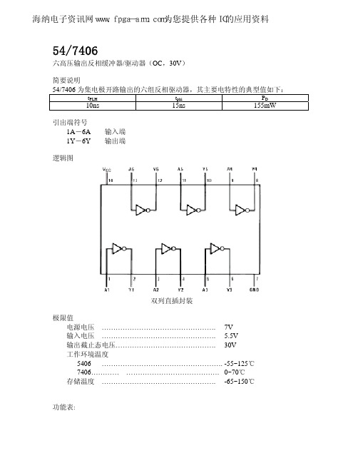
54/7406
六高压输出反相缓冲器/驱动器(OC,30V)
简要说明
54/7406 为集电极开路输出的六组反相驱动器,其主要电特性的典型值如下:
tPLH
10ns
tphl
15ns
PD
155mW
引出端符号 1A-6A 1Y-6Y
输入端 输出端
功能表:
海纳电子资讯网www.fpga-arm.com为您提供各种IC的应用资料
推荐工作条件:
电源电压 VCC
输入高电平电压ViH 输入低电平电压ViL 输出截止态电压 VO(OFF) 输出低电平电流IOL
5406/7406
最小
额定
最大
54
4.5
5
5.5
74
4.75
5
5.25Biblioteka 20.830
54
30
74
逻辑图
双列直插封装
极限值 电源电压 …………………………………………. 7V 输入电压 …………………………………………. 5.5V 输出截止态电压……………………………………. 30V 工作环境温度 5406 ……………………………………………. -55~125℃ 7406………… …………………………………. 0~70℃ 存储温度 …………………………………………. -65~150℃
测试条件 Vcc =5V,CL=15Pf ,RL=110Ω
‘06 最大 15 23
单位
V V V V mA
单位
V uA V mA uA mA mA mA
单位
ns ns
Vcc=最大,VI=5.5V Vcc=最大,VIH=2.4V Vcc=最大,VIL=0.4V
UL746C中文版(电器中塑料评估)
39 39 39 40 40
40 41 41
November 29,2001(第 5 版) Polymeric Materials – Use in Electrical Equipment Evaluations – UL 746C (对使用于电器中的塑料的评估) 4
项目
内容
性能测试
49 概述
50 整机耐电弧测试
November 29,2001(第 5 版) Polymeric Materials – Use in Electrical Equipment Evaluations – UL 746C (对使用于电器中的塑料的评估) 1
辅助论坛(/) 致力于打造成为全球最大、最专业的教程资源网站。这里集中了 ProE教程、SolidWorks、Unigraphics教程、3DMAX教程、AutoCAD教程、CorelDRAW教程、 Photoshop教程等常见软件的教程资源网站与技术交流论坛!
November 29,2001(第 5 版) Polymeric Materials – Use in Electrical Equipment Evaluations – UL 746C (对使用于电器中的塑料的评估) 6
IC746PRO中文说明书
9-2 調諧器的操作 10 設定模式
10-1 選取設定模式 10-2 設定模式項目 11 調整 11-1 調諧旋鈕的制動 11-2-頻率校正 11-3 測量 SWR 11-4 調整 LCD 12 組裝與連接 12-1 前面板 12-2 後面板 12-3 選取位置 12-4 電源供應器的連接 12-5 接㆞ 12-6 ㆝線 12-7 數據通訊 12-8 RTTY 的連接 12-9 遠端插座 13 配件的安裝 13-1 打開收發機的機殼 13-2 UT-102 語音合成元件 13-3 CR-282 高穩定度石英晶體元件 13-4 選購的㆗頻濾波器 13-5 線性功率放大器的連接 13-6 外部㆝線調諧器的連接 14 保養 14-1 更換保險絲 14-2 重設 CPU 14-3 故障排除 15 規格與選購的配件 15-1 規格 15-2 選購的配件
ul746 对塑胶原料储存的要求

ul746 对塑胶原料储存的要求下载提示:该文档是本店铺精心编制而成的,希望大家下载后,能够帮助大家解决实际问题。
文档下载后可定制修改,请根据实际需要进行调整和使用,谢谢!本店铺为大家提供各种类型的实用资料,如教育随笔、日记赏析、句子摘抄、古诗大全、经典美文、话题作文、工作总结、词语解析、文案摘录、其他资料等等,想了解不同资料格式和写法,敬请关注!Download tips: This document is carefully compiled by this editor. I hope that after you download it, it can help you solve practical problems. The document can be customized and modified after downloading, please adjust and use it according to actual needs, thank you! In addition, this shop provides you with various types of practical materials, such as educational essays, diary appreciation, sentence excerpts, ancient poems, classic articles, topic composition, work summary, word parsing, copy excerpts, other materials and so on, want to know different data formats and writing methods, please pay attention!UL746 对塑胶原料储存的要求塑胶原料的储存质量直接影响其在生产中的表现和最终产品的质量。
UL746C(翻译及课程笔记版)
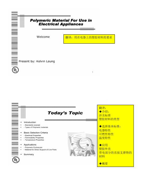
翻译:用在电器上的塑胶材料的要求翻译:◆介绍:涉及标准塑胶材料的类型◆选择基本标准:电器特性可燃性特性温度特性◆应用塑胶外壳带电部分的直接支撑物的材料◆概要翻译:UL标准UL746C—使用在电器设备上的塑胶材料的评估。
笔记:主要为如何根据黄卡上的信息选择材料材料类型:热塑性塑胶热固性人造橡胶(弹性体)翻译: 电气特性:抗灼热丝点燃(HWI ):点燃缠绕着电阻丝的样品的平均秒数,其中电阻丝通以规定等级的电流。
等级分为:0、1、2、3、4、5笔记:把发热丝包在材料的外表面,通电,看材料燃烧时间的长短,如在7S 内燃烧就为第5个等级。
样品消耗功率:0.26W/mm翻译: 电气特性:抗电弧点燃(HAI ):当以标准的速度在材料表面施加电弧,点燃材料的电弧数量。
笔记:两个高压电极之间按一定的频率产生电弧,看多少个电弧能使材料燃烧,共分为0、1、2、3、4个等级固定电极可移动电极 条形样板翻译:电气特性:相对漏电起痕指数(CTI):用于评估材料暴露在不同污染环境下的漏电可能导致的火灾或电击危害。
笔记:CTI:材料抗污染的程度,材料表面一段时间后会堆积一定的污染物,在材料的两端连接两个电极,看污染到多少程度会使材料表面两个电极相通。
分为0、1、2、3、4、5个等级CTI数字与厚度没有关系翻译:在塑胶材料库中的HWI、HAI、CTI(+)――原始材料和不超过50%的重量内含物的碾磨材料的混合,具有同样的基本材料特性。
(f1)――适于户外使用,并根据UL746C,暴露在紫外线下,水源和浸入水中的材料。
注意――1)色粉的材料名称要有后缀的字母和数字。
2)材料名称前面可以有“ZYT”,“MIN”,“ZEN”“DEL”“CRA”“RYN”这些前缀。
翻译:可燃性:基本可燃性等级HB、V-2、V-1、V-0次级可燃性等级5VB,5VAHF-1,HF-2,HBFVTM-2,VTM-1,VTM-0笔记:基本等级:主要根据火焰大小分类次级等级测试方法:如5VB,5VA,在燃烧的材料下放棉花,燃烧时的渣会使棉花燃起来就为5VA,燃不起来就是5VBVTM-2,VTM-1,VTM-0防火级别等同于V-2、V-1、V-0VTM为超薄片的含义,如马达上的绝缘纸在塑胶资料库中的火焰等级,笔记:可燃性等级看表中圈起部分(表格同表8)翻译:RIT:电气RTI,与关键电气绝缘特性联系在一起。
UL746C有关用在电器上的塑胶材料的要求

广东东菱凯琴集团UL746C用在电器上的塑胶材料的要求UL746C版本:第五版,2001译文版本:A翻译:审批:日期:目录介绍1. 范围2. 概述3. 术语外壳4. 概述5. 便携式无人照看的家用电器-用HB材料的要求5.1 概述5.2 电气连接5.3 靠近连接处的材料5.4 引线,套管,胶带6. 便携式器具(删掉)7. 固定式或驻立式器具(删掉)电气绝缘8. 材料属性8.1 概述8.2 未满足表 8.1的考虑9.内部挡板Performance Criteria10. 概述电气特性11. 相对漏电起痕指数(CTI)12.电气强度13. 抗电弧点燃(HAI)14. 抗灼热丝点燃(HWI)-过载测试或整机的灼热丝燃烧测试14.1 概述14.2 过载测试14.3 整机的灼热丝燃烧测试(GWEPT)15. Inclined plane tracking16. 体积电阻率燃烧性17. 燃烧性– 12mm高的火焰18. 燃烧性– 20mm高的火焰19. 燃烧性– 127mm高的火焰20. 外壳燃烧性– 746-5VS20.1 测试要求21. 外壳燃烧速率–大面积的部件22. 阻燃性涂层22.1 概述22.2 测试要求机械性能23. 抗挤压性能24. 抗冲击性尺寸变化25. 蠕变永久性26. 永久性26.1 概述26.2 维卡氏软化点26.3 热变形温度26.4 球压测试温度27. 抗紫外线辐射28. 浸水测试28.1 概述28.2 尺寸变化考虑到最终的使用29. 非正常测试30. Severe conditions热学性能31 模塑应力测试 Mold stress-relief distortion32 马达的输入功率33 模塑应力测试后的电源线拉力测试34 温度判断–概述35 Functinal-use temperature indices36 Generic thermal index37 relative thermal index(RTI)38 Relative thermal capability(RTC)39 Relative thermal capability (alternate)40 超过最高使用温度点的温度漂移Temperature excurtions beyond the maximum use temperature特殊用途41 概述–胶粘剂 adhesive42功能分析43 测试验证43.1 最终产品的用途分析43.2 环境的影响44 Coil forms45 PCB板上的涂层敷金属的部件Metallized parts46 概述47 Ductile coatings48 Brittle coatings测试49 概述49.1 要求49.2 电压表49.3 漂白布49.4 电压和频率50 最终产品的抗电弧燃烧测试51 过载测试52 燃烧性 - 12mm 高的火焰53燃烧性 - 20mm高的火焰54燃烧性 - 127mm高的火焰55 外壳的燃烧性- 746-5VS56 阻燃涂层测试57 抗挤压性58 抗冲击性59抗紫外线暴晒(耐候性)60 浸水测试61 非正常操作62 Severe conditions test63 模塑应力变形64 球压测试65马达的输入功率66 Relative thermal capability (RTC)67 Relative thermal capability(alternate)68 超过最高使用温度点的温度漂移- 举例Temperature excursion beyond the maximum use temperature 69温度判断–举例70温度判断–举例(Alternate RTC)71 胶粘剂- 特殊用途Coil Form72 PCB板上的涂层测试73 胶带粘性测试74 泄漏电流测试75 整机的灼热丝燃烧测试(GWEPT)标识76 标识附录A介绍1 范围1.1 以下为用在电器中的塑胶材料的要求和测试方法。
(整理)UL746C有关用在电器上的塑胶材料的要求.
广东东菱凯琴集团UL746C用在电器上的塑胶材料的要求UL746C版本:第五版,2001译文版本:A翻译:审批:日期:目录介绍1. 范围2. 概述3. 术语外壳4. 概述5. 便携式无人照看的家用电器-用HB材料的要求5.1 概述5.2 电气连接5.3 靠近连接处的材料5.4 引线,套管,胶带6. 便携式器具(删掉)7. 固定式或驻立式器具(删掉)电气绝缘8. 材料属性8.1 概述8.2 未满足表 8.1的考虑9.内部挡板Performance Criteria10. 概述电气特性11. 相对漏电起痕指数(CTI)12.电气强度13. 抗电弧点燃(HAI)14. 抗灼热丝点燃(HWI)-过载测试或整机的灼热丝燃烧测试14.1 概述14.2 过载测试14.3 整机的灼热丝燃烧测试(GWEPT)15. Inclined plane tracking16. 体积电阻率燃烧性17. 燃烧性– 12mm高的火焰18. 燃烧性– 20mm高的火焰19. 燃烧性– 127mm高的火焰20. 外壳燃烧性– 746-5VS20.1 测试要求21. 外壳燃烧速率–大面积的部件22. 阻燃性涂层22.1 概述22.2 测试要求机械性能23. 抗挤压性能24. 抗冲击性尺寸变化25. 蠕变永久性26. 永久性26.1 概述26.2 维卡氏软化点26.3 热变形温度26.4 球压测试温度27. 抗紫外线辐射28. 浸水测试28.1 概述28.2 尺寸变化考虑到最终的使用29. 非正常测试30. Severe conditions热学性能31 模塑应力测试 Mold stress-relief distortion32 马达的输入功率33 模塑应力测试后的电源线拉力测试34 温度判断–概述35 Functinal-use temperature indices36 Generic thermal index37 relative thermal index(RTI)38 Relative thermal capability(RTC)39 Relative thermal capability (alternate)40 超过最高使用温度点的温度漂移Temperature excurtions beyond the maximum use temperature特殊用途41 概述–胶粘剂 adhesive42功能分析43 测试验证43.1 最终产品的用途分析43.2 环境的影响44 Coil forms45 PCB板上的涂层敷金属的部件Metallized parts46 概述47 Ductile coatings48 Brittle coatings测试49 概述49.1 要求49.2 电压表49.3 漂白布49.4 电压和频率50 最终产品的抗电弧燃烧测试51 过载测试52 燃烧性 - 12mm 高的火焰53燃烧性 - 20mm高的火焰54燃烧性 - 127mm高的火焰55 外壳的燃烧性- 746-5VS56 阻燃涂层测试57 抗挤压性58 抗冲击性59抗紫外线暴晒(耐候性)60 浸水测试61 非正常操作62 Severe conditions test63 模塑应力变形64 球压测试65马达的输入功率66 Relative thermal capability (RTC)67 Relative thermal capability(alternate)68 超过最高使用温度点的温度漂移- 举例Temperature excursion beyond the maximum use temperature 69温度判断–举例70温度判断–举例(Alternate RTC)71 胶粘剂- 特殊用途Coil Form72 PCB板上的涂层测试73 胶带粘性测试74 泄漏电流测试75 整机的灼热丝燃烧测试(GWEPT)标识76 标识附录A介绍1 范围1.1 以下为用在电器中的塑胶材料的要求和测试方法。
安规常见的名词解释UL746C

工程开发参考资料制定:杨爱东审核:工程中心1安规常见的名詞解释UL746C1.触及零件—指零件位于人体直接或使用测试针或工具可以接触到的位置,或距开口处不远的位置。
2.有人看管的间歇工作家用电器—指家庭中不经常使用,或者一次使用时间很短,使用时有人看管的电器,如电动刀,电动开罐器,风筒之类。
3.分支电路—在布线系统中,分支电路是位于最终使用器具一边的部分,为永久接线设备提供接线端子,或为带电源插头器具提供插座插口。
4.相对漏电起痕电压—相对漏电起痕电压(CTI)的测量方法在UL 746A“Standard for Polymeric Materials – Short Term Property Evaluations”有介绍,介绍了固体绝缘材料在潮湿条件下的漏电起痕电压的测量方法。
漏电起痕(CTI)电压范围(伏)PLC 值600≤TI 0400≤TI<600 1250≤TI<400 2175≤TI<250 3100≤TI<175 40≤TI<100 55.绝缘保护涂层—涂覆于印刷线路板上的保护涂层,用以提高导体之间的绝缘强度,使其免受环境影响。
6.带电源线器具—指用电源线接到分支电路上的电器产品。
7.台式器具—指使用过程中支撑或固定于柜子,桌子或凳子上的器具。
8.装饰性零件—零件只用于装饰作用,而不是作为带电零件的绝缘外壳。
9.外壳—指产品的以下部分:a)将能引起电击的全部零件或一个零件屏蔽起来,和/或工程开发参考资料制定:杨爱东审核:工程中心2b)阻止产品内因电弧引起的火焰的扩散。
10。
接线端子—指安装人员可将电源线或其它连接线接到电路上的任何端子。
11.固定式器具—指其电源线永久连接到电路中的器具。
12.阻燃等级—材料的阻燃等级由UL 94 “Test for Flammability of Plastic Materials for Parts in Device and Appliance”所叙述的测试方法来求得。
UL培训
培训资料 仅供内部参考 (For Internal Use Only)
UL基础知识(4)
认可标志-用于UL认可服务Recognition・Service
•认可服务主要是针对元器件和材料实施的一种安全认证程序。
•认可服务所认可的元器件会被组装在成品中,所以元器件的使用有一定的许可条 件(Conditions of Acceptability).开关、电源、印刷板、电阻、变压器、电线、 插头、塑料材料等都是认可对象。
向工厂提供检验报告和差异通知(如有) UL工厂检验人员离开制造工厂
培训资料 仅供内部参考 (For Internal Use Only)
UL跟踪检验服务
跟踪检验服务的种类: 按照产品类别的不同,跟踪检验服务的实施方式大致分 成两大类(L类与R类)。跟踪检验细则中的授权页会 说明该文档内的产品是属于L类(type L)或是R类 (Type R)。通常R类产品的跟踪检验频率为每季度至 少一次。L类产品的跟踪检验频率取决于制造商使用 UL标签的数量。不同类别的产品在每季度的受检次数 有不同的要求。产品的检验频率在“加强检查 (Increased Monitoring Process,简称IMP)”的状态下 会有明显的增加。IMP通常针对不能按UL要求生产带 有UL标志的产品制造商。IMP是一个阶段性的特殊跟 踪检验程序。在UL确认制造商能按UL要求生产带有 UL标志的产品后,IMP会被取消。
UL TRAINING MATERIAL UL培训资料
Prepared By:Qunzhu Zhao/Kezhen Bi May 2012
培训资料 仅供内部参考 (For Internal Use Only)
目录
UL简介 UL认证流程 UL基础知识 UL跟踪检验服务 UL追溯性要求(一致性要求) UL标志稽查要求 UL检验、测量、测试设备校验规范要求 UL FUS Procedure(Uor Internal Use Only)
陶氏POE7467
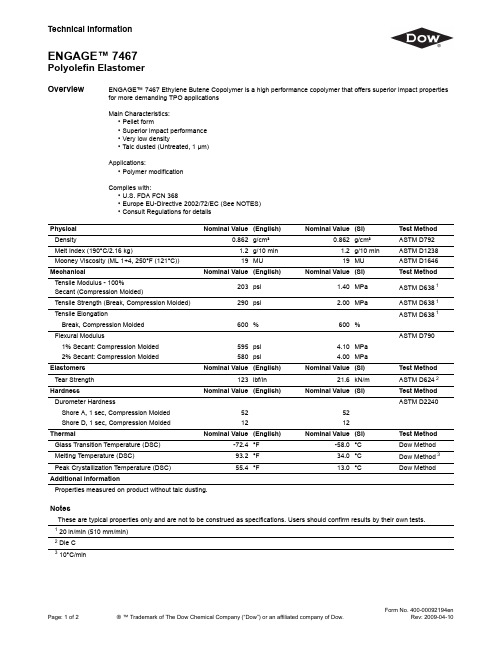
TechnicalInformationENGAGE™ 7467Polyolefin ElastomerPage:1of 2®™Trademark of The Dow Chemical Company (“Dow”)or an affiliated company of Dow.Form No.400-00092194enRev:2009-04-10OverviewENGAGE™7467Ethylene Butene Copolymer is a high performance copolymer that offers superior impact properties for more demanding TPO applicationsMain Characteristics:•Pellet form•Superior impact performance •Very low density•Talc dusted (Untreated,1µm)Applications:•Polymer modificationComplies with:•U.S.FDA FCN 368•Europe EU-Directive 2002/72/EC (See NOTES)•Consult Regulations for detailsPhysical Nominal Value (English)Nominal Value (SI)Test Method Density0.862g/cm³0.862g/cm³ASTM D792Melt Index (190°C/2.16kg)1.2g/10min 1.2g/10min ASTM D1238Mooney Viscosity (ML 1+4,250°F (121°C))19MU19MUASTM D1646MechanicalNominal Value (English)Nominal Value (SI)Test Method Tensile Modulus -100%Secant (Compression Molded)203psi 1.40MPa ASTM D638 1Tensile Strength (Break,Compression Molded)290psi 2.00MPa ASTM D638 1Tensile ElongationASTM D638 1Break,Compression Molded 600%600%Flexural ModulusASTM D7901%Secant:Compression Molded 595psi 4.10MPa 2%Secant:Compression Molded 580psi4.00MPaElastomers Nominal Value (English)Nominal Value (SI)Test Method Tear Strength 123lbf/in21.6kN/mASTM D624 2HardnessNominal Value (English)Nominal Value (SI)Test Method Durometer HardnessASTM D2240Shore A,1sec,Compression Molded 52 52 Shore D,1sec,Compression Molded 1212ThermalNominal Value (English)Nominal Value (SI)Test Method Glass Transition Temperature (DSC)-72.4°F -58.0°C Dow Method Melting Temperature (DSC)93.2°F 34.0°C Dow Method 3Peak Crystallization Temperature (DSC)55.4°F13.0°CDow MethodAdditional InformationProperties measured on product without talc dusting.NotesThese are typical properties only and are not to be construed as ers should confirm results by their own tests.1 20in/min (510mm/min)2 Die C 310°C/minPage:2of2®™Trademark of The Dow Chemical Company(“Dow”)or an affiliated company of Dow.Form No.400-00092194enRev:2009-04-10Product Stewardship The Dow Chemical Company and its subsidiaries(“Dow”)has a fundamental concern for all who make, distribute,and use its products,and for the environment in which we live.This concern is the basis for our Product Stewardship philosophy by which we assess the safety,health,and environmental information on our products and then take appropriate steps to protect employee and public health and our environment. The success of our Product Stewardship program rests with each and every individual involved with Dow products─from the initial concept and research,to manufacture,use,sale,disposal,and recycle of each product.Customer Notice Dow strongly encourages its customers to review both their manufacturing processes and their applications of Dow products from the standpoint of human health and environmental quality to ensure that Dow products are not used in ways for which they are not intended or tested.Dow personnel are available to answer your questions and to provide reasonable technical support.Dow product literature, including safety data sheets,should be consulted prior to use of Dow products.Current safety data sheets are available from Dow.Medical Applications Policy NOTICE REGARDING MEDICAL APPLICATION RESTRICTIONS:Dow will not knowingly sell or sample any product or service(“Product”)into any commercial or developmental application that is intended for: a.long-term or permanent contact with internal bodily fluids or tissues.“Long-term”is contact whichexceeds72continuous hours;e in cardiac prosthetic devices regardless of the length of time involved(“cardiac prosthetic devices”include,but are not limited to,pacemaker leads and devices,artificial hearts,heart valves,intra-aortic balloons and control systems,and ventricular bypass-assisted devices);e as a critical component in medical devices that support or sustain human life;ore specifically by pregnant women or in applications designed specifically to promote or interfere withhuman reproduction.Dow requests that customers considering use of Dow products in medical applications notify Dow so that appropriate assessments may be conducted.Dow does not endorse or claim suitability of its products for specific medical applications.It is the responsibility of the medical device or pharmaceutical manufacturer to determine that the Dow product is safe,lawful,and technically suitable for the intended use.DOW MAKES NO WARRANTIES,EXPRESS OR IMPLIED,CONCERNING THE SUITABILITY OF ANY DOW PRODUCT FOR USE IN MEDICAL APPLICATIONS.Disclaimer NOTICE:No freedom from infringement of any patent owned by Dow or others is to be inferred.Because use conditions and applicable laws may differ from one location to another and may change with time,theCustomer is responsible for determining whether products and the information in this document areappropriate for the Customer’s use and for ensuring that the Customer’s workplace and disposal practicesare in compliance with applicable laws and other governmental enactments.Dow assumes no obligationor liability for the information in this document.NO WARRANTIES ARE GIVEN;ALL IMPLIEDWARRANTIES OF MERCHANTABILITY OR FITNESS FOR A PARTICULAR PURPOSE AREEXPRESSLY EXCLUDED.NOTICE:If products are described as“experimental”or“developmental”:(1)product specifications maynot be fully determined;(2)analysis of hazards and caution in handling and use are required;(3)there isgreater potential for Dow to change specifications and/or discontinue production;and(4)although Dowmay from time to time provide samples of such products,Dow is not obligated to supply or otherwisecommercialize such products for any use or application whatsoever.Additional Information North America Europe/Middle East+800-3694-6367 U.S.&Canada:1-800-441-4369+32-3-450-22401-989-832-1426Italy:+800-783-825 Mexico:+1-800-441-4369Latin America South Africa+800-99-5078 Argentina:+54-11-4319-0100Brazil:+55-11-5188-9000Colombia:+57-1-219-6000Asia Pacific+800-7776-7776 Mexico:+52-55-5201-4700+603-7965-5392 This document is intended for use within Asia Pacific,Europe,Latin America,North AmericaPublished:2006-11-07©2010The Dow Chemical Company。
IN746A中文资料

1N746A - 1N759A SeriesDO-35ã1997 Fairchild Semiconductor CorporationTRADEMARKSACEx™CoolFET™CROSSVOLT™E 2CMOS TM FACT™FACT Quiet Series™FAST ®FASTr™GTO™HiSeC™The following are registered and unregistered trademarks Fairchild Semiconductor owns or is authorized to use and is not intended to be an exhaustive list of all such trademarks.LIFE SUPPORT POLICYFAIRCHILD’S PRODUCTS ARE NOT AUTHORIZED FOR USE AS CRITICAL COMPONENTS IN LIFE SUPPORTDEVICES OR SYSTEMS WITHOUT THE EXPRESS WRITTEN APPROV AL OF FAIRCHILD SEMICONDUCTOR CORPORA TION.As used herein:ISOPLANAR™MICROWIRE™POP™PowerTrench™QS™Quiet Series™SuperSOT™-3SuperSOT™-6SuperSOT™-8TinyLogic™1. Life support devices or systems are devices or systems which, (a) are intended for surgical implant intothe body, or (b) support or sustain life, or (c) whosefailure to perform when properly used in accordancewith instructions for use provided in the labeling, can be reasonably expected to result in significant injury to the user.2. A critical component is any component of a lifesupport device or system whose failure to perform can be reasonably expected to cause the failure of the life support device or system, or to affect its safety or effectiveness.PRODUCT STATUS DEFINITIONS Definition of TermsDatasheet Identification Product Status Definition Advance InformationPreliminary No Identification Needed Obsolete This datasheet contains the design specifications for product development. Specifications may change in any manner without notice.This datasheet contains preliminary data, andsupplementary data will be published at a later date.Fairchild Semiconductor reserves the right to make changes at any time without notice in order to improve design.This datasheet contains final specifications. Fairchild Semiconductor reserves the right to make changes at any time without notice in order to improve design.This datasheet contains specifications on a product that has been discontinued by Fairchild semiconductor.The datasheet is printed for reference information only.Formative or In DesignFirst ProductionFull ProductionNot In ProductionDISCLAIMERFAIRCHILD SEMICONDUCTOR RESERVES THE RIGHT TO MAKE CHANGES WITHOUT FURTHER NOTICE TO ANY PRODUCTS HEREIN TO IMPROVE RELIABILITY , FUNCTION OR DESIGN. FAIRCHILD DOES NOT ASSUME ANY LIABILITY ARISING OUT OF THE APPLICATION OR USE OF ANY PRODUCT OR CIRCUIT DESCRIBED HEREIN; NEITHER DOES IT CONVEY ANY LICENSE UNDER ITS PATENT RIGHTS, NOR THE RIGHTS OF OTHERS.。
P746 Setting Guide_h
MiCOM P746Setting GuideToutes les informations contenues dans ce document sont la propriété exclusive de Schneider Electric Industry S.A.S. Elles ne peuvent être divulguées ou utilisées sans notre accord écrit préalable.All the information contained in this document is the exclusive property of Schneider Electric Industry S.A.S. It may not be revealed or used without our priorT a b l e o f c o n t e n t s1INTRODUCTION 87 BB /P (3)2TERMINAL SETTINGS (ALL PROTECTIONS) (4)387BB PHASE SETTINGS (SOLIDLY EARTHED NETWORK SCHEMES) (5)487BB SETTINGS (COMPENSATED EARTHED NETWORK SCHEMES) (10)550BF (11)6DEAD ZONE (12)1 INTRODUCTION 87 BB /PThis document is the setting manual to configure the numerical busbar protection.87 BB /PFor Solid earthed networks:2 TERMINAL SETTINGS (ALL PROTECTIONS)For each Terminal (connected to the secondary of a High voltage CT):2.1 CT RatiosOnly 3 values have to be known and entered:1. Phase CT Primary current (from 1 to 30000 A) given by the manufacturer.2. Phase CT secondary current (1 or 5 A) given by the manufacturer.3. Polarity (Standard (towards the busbar) or Inverted (opposite to the busbar)Note: For the busbar protection reference 2 values have to be entered:1. Phase reference CT Primary current (from 1 to 30000 A).2. Phase reference CT secondary current (1 or 5 A).2.2 VT RatiosOnly 3 values have to be known and entered:Phase VT Primary voltage (from 100 to 100 kV) given by the manufacturer.Phase VT Secondary voltage (80 or 140 V) given by the manufacturer.3 87BB PHASE SETTINGS (SOLIDLY EARTHED NETWORK SCHEMES) 3.1 Sub-station featuresOnly 7 values have to be known:1. Number of independent busbars2. Minimum load current in a feeder3. Maximum load current in a feeder4. Maximum load current in a busbar5. Biggest CT primary winding6. Minimum short-circuit value (phase to phase) in a busbar7. Voltage used (Yes or No)3.2 Idiff_Ibias Setting calculation spreadsheetEnter in the Idiff_Ibias spreadsheet the 7 values here above listed and you’ll be able to choose thevalues hereafter listed.It is important to know that if the minimum internal fault detection is set below the maximum load an additional criterion such as voltage must be used.3.3 Differential Busbar Protection1. ID>1 (from 5 A to 500 A (primary value)) as high as possible2. Slope k1 (ID>1) (from 0% to 50%), recommendation is 10%3. ID>2 (from 50 A to 50000 A (primary value)) as low as possible4. Slope k2 (ID>2) (from 20% to 90%), recommendation is 60% (50% for China)5. IDCZ>2 (from 50 A to 50000 A (primary value)) as low as possible6. Slope kCZ (IDCZ>2) (from 0% to 90%), recommendation is 30% (25% for China)7. ID>1 Alarm Timer (from 0 to 100 s) shall be greater than the longest protection time (such asline, overcurrent, etc…)8. Phase comparison threshold recommendation depends on the number of infeedsExplanations of the values:1. ID>1 shall be higher than 2% of the biggest CT to not detect noise coming from it and lessthan 80% of the minimum load of a feeder to detect the minimum load imbalance in case of aproblem in that particular feeder.2. Slope k1 recommendation is 10% to meet 10Pxx current transformers3. ID>2 shall be below twice the maximum load for the phase comparison algorithm to pickup theload and if possible below 50% of the minimum fault to be sub-cycle (80% otherwise) and if novoltage criteria is used above 100% (and when possible 120% to allow 20% margin) of thebiggest load to not maloperate in case of CT short-circuited or open circuitNote: voltage criteria can be used for single busbar only in one box mode.and less than 80% of the minimum fault current to operate sub-cycle for the minimum fault (and 50% when possible to be sure to always operate in 13ms)4. Slope k2 (ID>2)a. Recommendation is 60%To be always stable in the worth CT ratio conditions (between the biggest CT andthe smallest CT).b. Recommendation is 50% for ChinaIn China, the requirement is to be able to detect a resistive fault equal to 50% of thebias current.5. IDCZ>2 same as ID>26. Slope kCZ (IDCZ>2)a. Recommendation is 30%kCZ depends on the number of busbars:•n busbars (Independent busbars)• A minimum internal short-circuit value (Icc min (1 busbar))A maximum load for a busbar (IloadMax (1 busbar)).••when all these buses are independent (bus sectionalizers open)•the maximum load is on all the buses (biggest bias current)•The internal short-circuit value is minimum.During the internal fault:•the bias current is: Icc min (1 busbar) + (n-1) x IloadMax (1 busbar) •the differential current is: Icc min (1 busbar)Thus the biggest slope for the Check Zone to detect the fault is: ________________Icc min (1 busbar)________________________((Independent busbars - 1) x IloadMax (1 busbar)) + Icc min (1 busbar)If for example:There are 3 buses and Icc min = IloadMax, the slope must be below 33%Case Half-Breaker Scheme:P746 has to be able to trip for a fault that is counted twice by the Check Zone (forexample one and half circuit breaker substation).For a one and half breaker scheme there are:• 2 busbars (Independent busbars)• A minimum internal short-circuit value (Icc min (1 busbar))•A maximum load for a busbar (IloadMax (1 busbar)).The worst case is: •when the Fault (Icc) is split in 2 and goes as well through the opposite busbar •the maximum load is on the 2 buses (biggest bias current) • The internal short-circuit value is minimum.During the internal fault: •the CZ bias current is: 2 x Icc min (1 busbar) + 4 x IloadMax (1 busbar) •the CZ differential current is: Icc min (1 busbar)Thus the biggest slope for the Check Zone to detect the fault is:___________Icc min (1 busbar)___________(4 x IloadMax (1 busbar)) + 2 x Icc min (1 busbar)If for example:Icc min = IloadMax, the slope must be below 17%b. Recommendation is 25% for ChinaIn China, the requirement is to be able to trip for a resistive fault that is counted twiceby the Check Zone (for example one and half circuit breaker substation).7. ID>1 Alarm Timer to not operate for an external fault shall be greater than the longestprotection time (such as line, overcurrent, etc…)8. Phase comparisonPhase comparison is used to define the minimum current to be included in the phasecomparison blocking algorithm. We cannot consider any level of current in phase comparison because even for an internal fault some small currents can flow out (this situation depends on fault impedance).The requirement for phase comparison minimum threshold is to be able todetect a through fault that is fed by the infeeds;It depends on :•The minimum internal short-circuit threshold (ID>2)•The maximum number of infeeds and their CT primary nominal currentsThe worst scenario is when the CT is fully saturated and the differential algorithm picks up on the ID>2 threshold. The phase comparison must block the trip by detecting the incomingcurrents:We assume the infeeds will contribute to the ID>2 fault in proportion to their CT primarynominal current (worst situation).Then we need for each infeed , phase comparison threshold to be lower than :ID>2 x (In CT / Σ(In CTs infeeds))And Phase comp.= ID>2 / (In CT / Σ(In CTs infeeds)) / In CT,So for any infeed, Phase comp. = ID>2 / Σ(In CTs infeeds))We take 80% of this value so that to keep sufficient margin. Recommended setting is then : :Phase comp. = 0.8 x ID>2 / Σ(In CTs infeeds)Phase comp. setting % = 100 x 0.8 x ID>2 / Σ(In CTs infeeds)4 87BB SETTINGS (COMPENSATED EARTHED NETWORK SCHEMES)4.1 Sub-station featuresOnly 4 values have to be known:1. Maximum load current in a feeder2. Minimum phase to phase fault current (Ph-Ph min.) in a busbar3. Maximum single phase steady state faulty current (Ph-N Max.) in a busbar4. Number of independent busbars5. Maximum number of infeeds4.2 Differential Busbar Protection9 values have to be chosen:1. ID>1 (from 5 A to 500 A (primary value)), recommendation equal to 1,2 x (Ph-N Max.)2. Slope k1 (ID>1) (from 0% to 50%), recommendation is 10%.3. ID>1 Alarm Timer (from 0 to 100 s) shall be greater than the longest Busbar protection time4. Slope k2 (from 20% to 90%) but recommendation 65%.5. ID>2 (from 50 A to 50000 A (primary value)), recommendation is:6. Lower than 0,8 x (Ph-Ph min) and Higher than 1,2 x Iload Max and if possible equal to 6 x(ID>1).7. Slope kCZ (from 0% to 90%) but recommendation 30%.8. IDCZ>2 (from 50 A to 50000 A (primary value)), recommendation is:9. Lower than 0,8 x (Ph-Ph min) and Higher than 1,2 x Iload Max and if possible equal to 6 x(ID>1).10. Phase comparison recommendation is around or below 50%Explanations of the values:1. ID>1 shall be higher than 120% of the highest phase to neutral fault to not operate in case ofphase to neutral fault.2. Slope k1 recommendation is 10% to meet 10Pxx current transformers3. ID>1 Alarm Timer to not operate for an external fault shall be greater than the longestprotection time (such as line, overcurrent, etc…)4. Slope k2 (ID>2) recommendation is 65%To be always stable in the worth CT ratio conditions (between the biggest CT andthe smallest CT). 60% is OK as long as the CT ratio is less than 5.5. ID>2 shall be lower than 80% of the minimum phase to phase fault current to operate sub-cyclefor the minimum fault and higher than 120% Iload Max (120% to allow 20% margin) and ifpossible equal to 6 x (ID>1) to be insensitive to the worth CT saturation.6. IDCZ>2 same as ID>27. Slope kCZ (IDCZ>2) recommendation is 30%The requirement is to be able to trip for a fault that is counted twice by the CheckZone (for example one and half circuit breaker substation).5 50BFInternalInitiationTBF2 should be equal to the maximum opening time + 30 ms*5.1.2 External initiation3. Local retrip delay tBF34. Bactrip delay tBF4TBF4 should be equal to the maximum opening time + 30 ms**: In case of external relaying, add the relay additional closing time.Important note: if the external trip command is not longer than TBF4, add a dwell gate set longer than TBF4 in the PSL.Note: The CB fail alarm is raised as soon as tBF1 or tBF3 are reached.6 DEAD ZONEFor each Terminal connected to a Feeder Circuit Breaker (but not on the coupling)6.1 Terminal SETTINGSFor the phase:I>DZ must be below 80% of the minimum Dead Zone fault (and if possible bigger than the maximumload).I>DZ Time delay must be at least 50ms if the CB status positions are used (any value otherwise)For the Neutral (if used):IN>DZ must be below 80% of the minimum Dead Zone earth fault.IN>DZ Time delay must be at least 50ms if the CB status positions are used (any value otherwise)Important note:When a dead zone fault occurs and the bias current flowing through the busbar is small, there could be a maloperation of the 87BB.To prevent that, it is recommended to enable an additional criterion such as voltage (voltage criteria can。
UL746C(翻译及课程笔记版)学习资料
U L746C(翻译及课程笔记版)翻译:用在电器上的塑胶材料的要求翻译:◆介绍:涉及标准塑胶材料的类型◆选择基本标准:电器特性可燃性特性温度特性◆应用塑胶外壳带电部分的直接支撑物的材料◆概要翻译:UL标准UL746C—使用在电器设备上的塑胶材料的评估。
笔记:主要为如何根据黄卡上的信息选择材料材料类型:热塑性塑胶热固性人造橡胶(弹性体)翻译:电气特性:抗灼热丝点燃(HWI):点燃缠绕着电阻丝的样品的平均秒数,其中电阻丝通以规定等级的电流。
等级分为:0、1、2、3、4、5笔记:把发热丝包在材料的外表面,通电,看材料燃烧时间的长短,如在7S内燃烧就为第5个等级。
消耗功率:0.26W/mm样品翻译: 电气特性: 抗电弧点燃(HAI ):当以标准的速度在材料表面施加电弧,点燃材料的电弧数量。
笔记:两个高压电极之间按一定的频率产生电弧,看多少个电弧能使材料燃烧,共分为0、1、2、3、4个等级固定电极可移动电极条形样板翻译: 电气特性:相对漏电起痕指数(CTI ):用于评估材料暴露在不同污染环境下的漏电可能导致的火灾或电击危害。
笔记:CTI :材料抗污染的程度,材料表面一段时间后会堆积一定的污染物,在材料的两端连接两个电极,看污染到多少程度会使材料表面两个电极相通。
分为0、1、2、3、4、5个等级 CTI 数字与厚度没有关系翻译:在塑胶材料库中的HWI、HAI、CTI(+)――原始材料和不超过50%的重量内含物的碾磨材料的混合,具有同样的基本材料特性。
(f1)――适于户外使用,并根据UL746C,暴露在紫外线下,水源和浸入水中的材料。
注意――1)色粉的材料名称要有后缀的字母和数字。
2)材料名称前面可以有“ZYT”,“MIN”,“ZEN”“DEL”“CRA”“RYN”这些前缀。
翻译:可燃性:基本可燃性等级HB、V-2、V-1、V-0次级可燃性等级5VB,5VAHF-1,HF-2,HBFVTM-2,VTM-1,VTM-0笔记:基本等级:主要根据火焰大小分类次级等级测试方法:如5VB,5VA,在燃烧的材料下放棉花,燃烧时的渣会使棉花燃起来就为5VA,燃不起来就是5VBVTM-2,VTM-1,VT在塑胶资料库中的火焰等级,笔记:可燃性等级看表中圈起部分(表格同表8)翻译:RIT:电气RTI,与关键电气绝缘特性联系在一起。
UL746A

Copyright by the Underwriters Laboratories Inc Sat Apr 17 09:14:38 2004
Copyright by the Underwriters Laboratories Inc Sat Apr 17 09:14:38 2004
Copyright by the Underwriters Laboratories Inc Sat Apr 17 09:14:39 2004
Copyright by the Underwriters Laboratories Inc Sat Apr 17 09:14:26 2004
Copyright by the Underwriters Laboratories Inc Sat Apr 17 09:14:26 2004
Copyright by the Underwriters Laboratories Inc Sat Apr 17 09:14:27 2004
Copyright by the Underwriters Laboratories Inc Sat Apr 17 09:14:31 2004
Copyright by the Underwriters Laboratories Inc Sat Apr 17 09:14:31 2004
Copyright by the Underwriters Laboratories Inc Sat Apr 17 09:14:32 2004
Copyright by the Underwriters Laboratories Inc Sat Apr 17 09:14:33 2004
Copyright by the Underwriters Laboratories Inc Sat Apr 17 09:14:33 2004
美国户外防紫外线(f1)-UL卡
.
;. 美国户外防紫外线(f1)认证-UL卡
(f1)(f2)是UL卡中的注释记号,表示适合室外使用并且符合UL746C规格的耐久性(紫外线暴露、耐水、浸渍)。
(f1) -
Suitable for outdoor use with respect to exposure to Ultraviolet Light, Water Exposure and Immersion in accordance with UL 746C.
(f2) -
Subjected to one or more of the following tests: Ultraviolet Light, Water Exposure or Immersion in accordance with UL 746C, where the acceptability for outdoor use is to be determined by UL
“f1”表示适合“紫外线暴露试验”和“水暴露试验和浸渍试验”两者而“f2”则表示适合其中一种试验。
“紫外线暴露试验”的条件是在双灯式封闭型碳弧下暴露720小时(*1),或在氙弧下暴露1000小时(*2)。
在这些条件下燃烧性等级保持不变则为合格。
原则上应使试验后的拉伸强度、弯曲强度、拉伸冲击强度、悬臂梁冲击强度、简支梁冲击强度等特性都保持在70%以上。
在“水暴露试验和浸渍试验”中,在70℃下用热水处理7天后燃烧性等级应保持不变。
此外还应使拉伸强度、弯曲强度、或拉伸冲击强度、悬臂梁冲击强度、简支梁冲击强度等特性都保持在50%以上。
(*1) ASTM G151, G153
(*2) ASTMG151、G155、黑板温度为63℃。
7460 第三章节 装置功能及实现原理
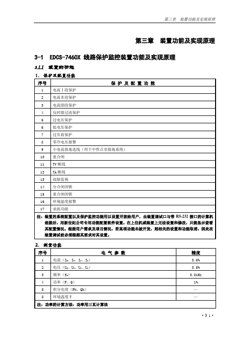
第三章装置功能及实现原理3-1 EDCS-7460X 线路保护监控装置功能及实现原理3.1.1 装置的功能·3-1·3.监视功能4.控制功能5.统计功能6.事件记录和故障录波EDCS-7460X保护监控装置支持事件记录和故障录波功能,与电力系统安全运行相关的所有事件均能进行记录,时间分辨率小于1ms,在线记录事件16条,掉电不丢失, 便于故障原因分析和设备缺陷诊断。
用户可根据运行需要,设定故障录波的触发方式(命令启动、开关量变位启动、保护启动时启动、保护动作启动)只要事件出现,装置就能自动将发生该事件前后的电流、电压、开关状态等信息完整真实的记录下来。
7.事故报警信号、故障报警信号产生原理及使用原则A.产生事故报警信号的原因·3-2··3-3·a . 各种保护动作事故信号;b . 开关量输入状态变化触发的事故信号。
B . 产生故障报警信号的原因a . 各种保护动作故障信号;b . 开关量输入状态变化触发的故障信号。
c . TA 、TV 断线报警信号;d . 控制电源失电报警信号;e . 分合回路断线报警信号;f . 装置温度越限报警信号。
C . 装置前面板有指示灯指示故障、事故信号,同时支持故障、事故信号继电器输出,用于连接事故音响、预告音响小母线。
D . 消除事故报警、故障报警信号操作报警出口根据需要可配置报警出口持续时间,报警输出整定时间返回;也可以直接通过主机或装置专用复归命令清除使报警出口继电器释放。
3.1.2 保护动作原理与逻辑1. 电流Ⅰ段保护动作判据:任一相电流大于电流Ⅰ段整定值,或有低压闭锁配置时任一线电压低于整定值条件下,启动延时,延时时间到驱动相应出口,并可设置TV 断线闭锁功能。
其中I 1zd 为Ⅰ段电流整定值,U 1zd 为Ⅰ段低电压整定值,t 1zd 为电流Ⅰ段保护出口延时。
电流Ⅰ段保护配置表:图3-1 电流Ⅰ段保护逻辑框图I b >I 1zd U ca <U 1zdTV 断线K b9K b2U bc <U 1zd U ab <U 1zd I c >I 1zdI a >I 1zd &K b1&≥1≥1&≥1启动录波事故报警出口发信号重合闸出口t 1zdK b10K b8K b3K b7K b4分闸·3-4·2. 电流Ⅱ段保护动作判据:任一相电流大于电流Ⅱ段整定值,或有低压闭锁配置时任一线电压低于整定值条件下,启动延时,延时时间到驱动相应出口,并可设置TV 断线闭锁功能。
- 1、下载文档前请自行甄别文档内容的完整性,平台不提供额外的编辑、内容补充、找答案等附加服务。
- 2、"仅部分预览"的文档,不可在线预览部分如存在完整性等问题,可反馈申请退款(可完整预览的文档不适用该条件!)。
- 3、如文档侵犯您的权益,请联系客服反馈,我们会尽快为您处理(人工客服工作时间:9:00-18:30)。
U L746C(翻译及课程
笔记版)
翻译:用在电器上的塑胶材料的要求
翻译:
◆介绍:
涉及标准
塑胶材料的类型
◆选择基本标准:
电器特性
可燃性特性
温度特性
◆应用
塑胶外壳
带电部分的直接支撑物的
材料
◆概要
翻译:
UL标准
UL746C—使用在电器设备上的塑胶材料的评估。
笔记:主要为如何根据黄卡上的信息选择材料
材料类型:
热塑性塑胶
热固性
人造橡胶(弹性体)
翻译:
电气特性:
抗灼热丝点燃
(HWI):点燃缠
绕着电阻丝的样品
的平均秒数,其中
电阻丝通以规定等
级的电流。
等级分
为:0、1、2、3、
4、5
笔记:把发热丝包
在材料的外表面,
通电,看材料燃烧
时间的长短,如在
7S内燃烧就为第5
个等级。
消耗功率:0.26W/mm
样品
翻译: 电气特性: 抗电弧点燃
(HAI ):当以标准的速度在材料表面施加电弧,点燃材料的电弧数量。
笔记:两个高压电极之间按一定的频率产生电弧,看多少个电弧能使材料
燃烧,共分为0、1、2、3、4个等级
固定电极
可移动电极
条形样板
翻译: 电气特性:
相对漏电起痕指数(CTI ):用于评估材料暴露在不同污染环境下的漏电可能导致的火灾或电击危害。
笔记:CTI :材料抗污染的程度,材料表面一段时间后会堆积一定的污染物,在材料的两端连接两个电极,看污染到多少程度会使材料表面两个电极相通。
分为0、1、2、3、4、5个等级 CTI 数字与厚度没有关系
翻译:
在塑胶材料库中的HWI、HAI、CTI(+)――原始材料和不超过50%的重量内含物的碾磨材料的混合,具有同样的基本材料特性。
(f1)――适于户外使用,并根据UL746C,暴露在紫外线下,水源和浸入水中的材料。
注意――1)色粉的材料名称要有后缀的字母和数字。
2)材料名称前面可以有“ZYT”,“MIN”,“ZEN”“DEL”“CRA”“RYN”这些前缀。
翻译:
可燃性:
基本可燃性等级
HB、V-2、V-1、V-0
次级可燃性等级
5VB,5VA
HF-1,HF-2,HBF
VTM-2,VTM-1,VT
M-0
笔记:
基本等级:主要根据火焰大小分
类
次级等级测试方法:如5VB,
5VA,在燃烧的材料下放棉
花,燃烧时的渣会使棉花燃起来
就为5VA,燃不起来就是5V
B
VTM-2,VTM-1,VT
在塑胶资料库中的火焰等级,
笔记:
可燃性等
级看表中
圈起部分
(表格同
表8)
翻译:
RIT:
电气RTI,与关键电气
绝缘特性联系在一起。
机械冲击RTI,与关键
冲击阻力,恢复力和弹性
特性联系在一起。
机械强度RTI:与冲击
抗力,恢复力,弹性不是
要点的地方的关键机械强
度联系在一起。
笔记:
RTI-相对温度值(最
高使用温度值)
RTIElec――支
持带电体(固定开关节
点)
RTIMechLm
翻译:塑胶资料库中的RTI值
笔记:
相关RTI值:看
表中圈起部分(表
格同表8)
翻译:应用――塑胶外壳
可燃性要求――UL746C表4.1的应用
外壳要求
适用范
便携式有人照看的家用电器所有其他的便
携式电器
其他
电器
最低的燃烧等级
翻译:问题:
家用手持式打蛋机的外壳的最低燃烧等级是多少?
家用多士炉的外壳的最低燃烧等级时多少?
商用手持式的打蛋机的最低燃烧要求是什么?
空气调节器的最低燃烧要求?
翻译:
应用:带电部件的直
接支撑物的材料
HWI和HAI要求
适用的塑胶材料
与非绝缘的带电体部
件的距离〈0.8m
m(不产生电弧的部
件)
与非绝缘的带电部件
的距离〈12.7m
m(会产生电弧的部
件)
CTI的要求。
