4 深紫外光刻Extreme UV lithography
极紫外光刻的原理及应用

极紫外光刻的原理及应用1. 引言极紫外光刻(又称EUV光刻)是一种先进的微影技术,它使用极紫外(EUV)光源进行光刻,并广泛应用于半导体制造中。
本文将介绍极紫外光刻的原理,以及它在半导体行业中的应用。
2. 极紫外光刻的原理极紫外光刻使用的光源是极紫外辐射,其波长为13.5纳米,远远短于传统光刻技术所使用的193纳米深紫外光。
极紫外光源的产生涉及复杂的物理过程,包括激光产生等离子体、从等离子体中产生极紫外光等步骤。
极紫外光刻使用的掩模还需要比传统光刻技术更高的反射率和更低的光散射率。
这是因为极紫外光源的波长很短,对掩模上细微缺陷的敏感度更高。
因此,制造高质量掩模对于极紫外光刻的成功应用至关重要。
3. 极紫外光刻的应用3.1 半导体制造极紫外光刻在半导体行业中有重要的应用。
随着半导体器件的尺寸越来越小,传统光刻技术已经无法满足制造高密度芯片的需求。
而极紫外光刻技术通过使用更短的波长,可以实现更高的分辨率和更小的线宽。
因此,它被广泛应用于半导体制造中,特别是在制造7纳米及以下尺寸的芯片中。
3.2 光刻机制造极紫外光刻技术的发展也推动了光刻机制造行业的发展。
光刻机是进行光刻过程的装置,它将掩模上的图形投影到光刻胶上,形成图案。
随着极紫外光刻技术的普及,对于光刻机的性能和稳定性的要求也越来越高。
因此,光刻机制造商需要不断改进技术,以适应极紫外光刻的要求。
3.3 研究和发展极紫外光刻作为一项新的微影技术,也需要不断的研究和发展。
许多研究机构和企业致力于提高极紫外光刻的性能和稳定性,以推动其应用的进一步发展。
此外,极紫外光刻在其他领域的应用也正在受到研究者的关注,如光学元件制造、生物医学和纳米技术等领域。
4. 极紫外光刻的优势和挑战极紫外光刻相比于传统光刻技术具有以下优势: - 更高的分辨率,可以制造更小的芯片尺寸。
- 更高的工艺容差,可以制造更复杂的器件结构。
- 更低的成本,可以提高生产效率。
然而,极紫外光刻也面临着一些挑战: - 极紫外光源的稳定性和可靠性需要进一步提高。
常用半导体中英对照表(建议收藏)

常用半导体中英对照表(建议收藏)01.常用半导体中英对照表离子注入机 ion implanterLSS理论 Lindhand Scharff and Schiott theory,又称“林汉德-斯卡夫-斯高特理论”。
沟道效应 channeling effect射程分布 range distribution深度分布 depth distribution投影射程 projected range阻止距离 stopping distance阻止本领 stopping power标准阻止截面 standard stopping cross section退火 annealing激活能 activation energy等温退火 isothermal annealing激光退火 laser annealing应力感生缺陷 stress-induced defect择优取向 preferred orientation制版工艺 mask-making technology图形畸变 pattern distortion初缩 first minification精缩 final minification母版 master mask铬版 chromium plate干版 dry plate乳胶版 emulsion plate透明版 see-through plate高分辨率版 high resolution plate, HRP超微粒干版 plate for ultra-microminiaturization掩模 mask掩模对准 mask alignment对准精度 alignment precision光刻胶 photoresist,又称“光致抗蚀剂”。
负性光刻胶 negative photoresist正性光刻胶 positive photoresist无机光刻胶 inorganic resist多层光刻胶 multilevel resist电子束光刻胶 electron beam resistX射线光刻胶 X-ray resist刷洗 scrubbing甩胶 spinning涂胶 photoresist coating后烘 postbaking光刻 photolithographyX射线光刻 X-ray lithography电子束光刻 electron beam lithography离子束光刻 ion beam lithography深紫外光刻 deep-UV lithography光刻机 mask aligner投影光刻机 projection mask aligner曝光 exposure接触式曝光法 contact exposure method接近式曝光法 proximity exposure method光学投影曝光法 optical projection exposure method 电子束曝光系统 electron beam exposure system分步重复系统 step-and-repeat system显影 development线宽 linewidth去胶 stripping of photoresist氧化去胶 removing of photoresist by oxidation等离子[体]去胶 removing of photoresist by plasma刻蚀 etching干法刻蚀 dry etching反应离子刻蚀 reactive ion etching, RIE各向同性刻蚀 isotropic etching各向异性刻蚀 anisotropic etching反应溅射刻蚀 reactive sputter etching离子铣 ion beam milling,又称“离子磨削”。
半导体一些术语的中英文对照

离子注入机 ion implanterLSS理论 Lindhand Scharff and Schiott theory 又称“林汉德-斯卡夫-斯高特理论”。
沟道效应 channeling effect射程分布 range distribution深度分布 depth distribution投影射程 projected range阻止距离 stopping distance阻止本领 stopping power标准阻止截面 standard stopping cross section退火 annealing激活能 activation energy等温退火 isothermal annealing激光退火 laser annealing应力感生缺陷 stress-induced defect择优取向 preferred orientation制版工艺 mask-making technology图形畸变 pattern distortion初缩 first minification精缩 final minification母版 master mask铬版 chromium plate干版 dry plate乳胶版 emulsion plate透明版 see-through plate高分辨率版 high resolution plate, HRP超微粒干版 plate for ultra-microminiaturization 掩模 mask掩模对准 mask alignment对准精度 alignment precision光刻胶 photoresist又称“光致抗蚀剂”。
负性光刻胶 negative photoresist正性光刻胶 positive photoresist无机光刻胶 inorganic resist多层光刻胶 multilevel resist电子束光刻胶 electron beam resistX射线光刻胶 X-ray resist刷洗 scrubbing甩胶 spinning涂胶 photoresist coating后烘 postbaking光刻 photolithographyX射线光刻 X-ray lithography电子束光刻 electron beam lithography 离子束光刻 ion beam lithography深紫外光刻 deep-UV lithography光刻机 mask aligner投影光刻机 projection mask aligner 曝光 exposure接触式曝光法 contact exposure method接近式曝光法 proximity exposure method光学投影曝光法 optical projection exposure method 电子束曝光系统 electron beam exposure system分步重复系统 step-and-repeat system显影 development线宽 linewidth去胶 stripping of photoresist氧化去胶 removing of photoresist by oxidation等离子[体]去胶 removing of photoresist by plasma 刻蚀 etching干法刻蚀 dry etching反应离子刻蚀 reactive ion etching, RIE各向同性刻蚀 isotropic etching各向异性刻蚀 anisotropic etching反应溅射刻蚀 reactive sputter etching离子铣 ion beam milling又称“离子磨削”。
“光刻机”的概念、技术及其在专利文献中的分布
“光刻机”的概念、技术及其在专利文献中的分布作者:王晓东来源:《中国科技术语》2014年第07期摘要:光刻机技术是大规模集成电路制造领域中的核心技术。
文章介绍了光刻机的概念、结构及其简要技术发展历程,并列举和解释了光刻机技术领域的重点技术术语,此外,针对光刻机技术的专利文献查新检索,总结了光刻机技术在专利文献分类中的分布情况。
关键词:光刻,光刻机,专利,IPC分类中图分类号:N04;TN4;TN30S 文献标识码:A 文章编号:1673-8578(2014)S1-0075-03Technology of Lithography Tool and its Distribution in Patent LiteraturesWANG XiaodongAbstract: Lithography tool is a core device used in the manufacture of integrated circuits. The concept, construction and development of lithography tool are introduced in this paper. Several important technical terms are commentated. The distribution of patent literatures concerning the stepper in the IPC classification is proposed for scitech novelty retrieval.Keywords: lithography,lithography tool,patent,IPC收稿日期:2014-06-28作者简介:王晓东(1977—),男,江苏苏州人,专利审查助理研究员,研究方向为光学及激光技术。
通信方式:wangxiaodong_2@。
光学光刻和极紫外光刻

光学光刻和极紫外光刻
光刻技术是半导体芯片制造过程中至关重要的一步。
它通过在芯片表面覆盖一层光刻胶,然后利用光刻机通过模板进行曝光和显影,最终将芯片上的电路图案转换成为实际的电路。
光刻技术中有两种主要的方法:光学光刻和极紫外光刻。
这两种技术在芯片制造中起到了不同的作用。
光学光刻是最早应用于芯片制造的光刻技术。
它使用的波长通常为365纳米,使用的曝光机制是直接投射法,即在芯片表面覆盖一层光刻胶,在模板上对所需的电路图案进行曝光,然后将曝光后的光刻胶中未曝光的部分显影掉,使其形成一层图案保护层,随后通过蚀刻工艺,将所需的电路图案刻在芯片上。
极紫外光刻是目前芯片制造领域中最先进的光刻技术。
它使用的波长为13.5纳米,比光学光刻使用的波长小了20倍,可以获得更小的细节。
极紫外光刻使用的曝光机制是反射式光刻,即通过将极紫外光通过附加反射镜反射到芯片表面上,然后将曝光后的光刻胶中未曝光的部分显影掉。
由于极紫外光刻使用的波长更小,因此可以获得更小的细节,可以实现更高的密度和更多的电路元件。
但是,极紫外光刻的成本非常高,需要昂贵的设备和高质量的光刻胶,因此只有一些大型半导体制造商才能使用这种技术。
使用光学光刻和极紫外光刻可以实现将电路图案传输到芯片上,这是制造高性能电子设备的关键一步。
有了这些技术,我们可以实现更小、更快和更强大的芯片,推动数码产品的创新和发展。
第一讲:紫外光刻技术
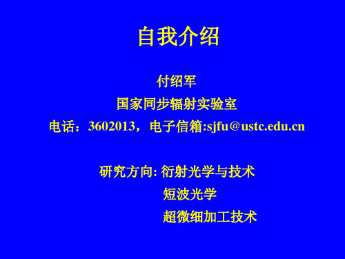
图形转移过程
• The layer of resist is exposed in specific areas through a mask. • Development washes away exposed resist. • In the additive process, material is deposited through the holes in the resist. • For a subtractive process, material is removed by ion milling through the holes in the resist. • In the final step, resist is removed.
主要研究工作
二.与国防建设有关的衍射光栅研制
1.高线密度软X射线透射光栅研制(ICF诊断) 1.高线密度软X射线透射光栅研制(ICF诊断) 高线密度软 诊断 2.软 射线Mach-Zehnder干涉仪用闪耀光栅( 射线激光) 2.软X射线Mach-Zehnder干涉仪用闪耀光栅(X射线激光) Mach 干涉仪用闪耀光栅 3.空间位置传感器用变间距光栅(飞机姿态闭环控制) 3.空间位置传感器用变间距光栅(飞机姿态闭环控制) 空间位置传感器用变间距光栅 4.X射线莫尔光栅( 射线激光) 4.X射线莫尔光栅(X射线激光) 射线莫尔光栅 5.大口径衍射光学元件研制(863专项) 5.大口径衍射光学元件研制(863专项) 大口径衍射光学元件研制 专项 脉宽压缩光栅 光束采样光栅 谐波分离光栅 束匀滑位相片
紫外光刻图形 截面照片
光透过掩模版( 要加工的图形) 光透过掩模版 ( 要加工的图形 ) , 照射在涂有 光刻胶( 光致抗蚀剂 ) 的被加工材料表面上 , 利用 光刻胶 ( 光致抗蚀剂) 的被加工材料表面上, 光刻胶的感光性和抗蚀性, 经过化学显影, 光刻胶的感光性和抗蚀性 , 经过化学显影 , 制作出 与掩模版图形一致的光刻胶图形(正胶情况) 与掩模版图形一致的光刻胶图形(正胶情况)。 光刻是复制微细图形的最有效手段之一, 光刻是复制微细图形的最有效手段之一,是制 作超大规模集成电路芯片的核心技术。 作超大规模集成电路芯片的核心技术。
半导体一些术语的中英文对照

半导体一些术语的中英文对照离子注入机ion implanterLSS理论Lindhand Scharff and Schiott theory 又称“林汉德-斯卡夫-斯高特理论”。
沟道效应channeling effect射程分布range distribution深度分布depth distribution投影射程projected range阻止距离stopping distance阻止本领stopping power标准阻止截面standard stopping cross section 退火annealing激活能activation energy等温退火isothermal annealing激光退火laser annealing应力感生缺陷stress-induced defect择优取向preferred orientation制版工艺mask-making technology图形畸变pattern distortion初缩first minification精缩final minification母版master mask铬版chromium plate干版dry plate乳胶版emulsion plate透明版see-through plate高分辨率版high resolution plate, HRP超微粒干版plate for ultra-microminiaturization 掩模mask掩模对准mask alignment对准精度alignment precision光刻胶photoresist又称“光致抗蚀剂”。
负性光刻胶negative photoresist正性光刻胶positive photoresist无机光刻胶inorganic resist多层光刻胶multilevel resist电子束光刻胶electron beam resistX射线光刻胶X-ray resist刷洗scrubbing甩胶spinning涂胶photoresist coating后烘postbaking光刻photolithographyX射线光刻X-ray lithography电子束光刻electron beam lithography离子束光刻ion beam lithography深紫外光刻deep-UV lithography光刻机mask aligner投影光刻机projection mask aligner曝光exposure接触式曝光法contact exposure method接近式曝光法proximity exposure method光学投影曝光法optical projection exposure method 电子束曝光系统electron beam exposure system分步重复系统step-and-repeat system显影development线宽linewidth去胶stripping of photoresist氧化去胶removing of photoresist by oxidation等离子[体]去胶removing of photoresist by plasma 刻蚀etching干法刻蚀dry etching反应离子刻蚀reactive ion etching, RIE各向同性刻蚀isotropic etching各向异性刻蚀anisotropic etching反应溅射刻蚀reactive sputter etching离子铣ion beam milling又称“离子磨削”。
半导体一些术语的中英文对照

半导体一些术语的中英文对照离子注入机ionimplanterLSS理论LindhandScharffandSchiotttheory 又称“林汉德-斯卡夫-斯高特理论”。
沟道效应channelingeffect射程分布rangedistribution深度分布depthdistribution投影射程projectedrange负性光刻胶negativephotoresist正性光刻胶positivephotoresist无机光刻胶inorganicresist多层光刻胶multilevelresist电子束光刻胶electronbeamresistX射线光刻胶X-rayresist刷洗scrubbing甩胶spinning涂胶photoresistcoating后烘postbaking光刻photolithographyX射线光刻X-raylithography电子束光刻electronbeamlithography离子束光刻ionbeamlithography深紫外光刻deep-UVlithography光刻机maskaligner投影光刻机projectionmaskaligner曝光exposure接触式曝光法contactexposuremethod接近式曝光法proximityexposuremethod光学投影曝光法opticalprojectionexposuremethod磷硅玻璃phosphorosilicateglass硼磷硅玻璃boron-phosphorosilicateglass钝化工艺passivationtechnology 多层介质钝化multilayerdielectricpassivation划片scribing电子束切片electronbeamslicing烧结sintering印压indentation热压焊thermocompressionbonding热超声焊thermosonicbonding冷焊coldwelding点焊spotwelding球焊ballbonding楔焊wedgebonding内引线焊接innerleadbonding外引线焊接outerleadbonding梁式引线beamlead装架工艺mountingtechnology附着adhesion封装packaging金属封装metallicpackagingAmbipolar双极的Ambienttemperature环境温度Amorphous无定形的,非晶体的Amplifier功放扩音器放大器Analogue(Analog)comparator模拟比较器Angstrom埃Anneal退火Anisotropic各向异性的Anode阳极Arsenic(AS)砷Auger俄歇Augerprocess俄歇过程Avalanche雪崩Avalanchebreakdown雪崩击穿Avalancheexcitation雪崩激发Backgroundcarrier本底载流子Backgrounddoping本底掺杂Backward反向Backwardbias反向偏置Ballastingresistor整流电阻Ballbond球形键合Band能带Bandgap能带间隙Barrier势垒Barrierlayer势垒层Barrierwidth势垒宽度Base基极Basecontact基区接触Basestretching基区扩展效应Basetransittime基区渡越时间Basetransportefficiency基区输运系数Base-widthmodulation基区宽度调制Basisvector基矢Bias偏置Bilateralswitch双向开关Binarycode二进制代码Binarycompoundsemiconductor二元化合物半导体Bipolar双极性的BipolarJunctionTransistor(BJT)双极晶体管Bloch布洛赫Blockingband阻挡能带Chargeconservation电荷守恒Chargeneutralitycondition电中性条件Chargedrive/exchange/sharing/transfer/storage电荷驱动/交换/共享/转移/存储Chemmicaletching化学腐蚀法Chemically-Polish化学抛光Chemmically-MechanicallyPolish(CMP)化学机械抛光Chip芯片Chipyield芯片成品率Clamped箝位Clampingdiode箝位二极管Cleavageplane解理面Clockrate时钟频率Clockgenerator时钟发生器Clockflip-flop时钟触发器Close-packedstructure密堆积结构Close-loopgain闭环增益Collector集电极Collision碰撞CompensatedOP-AMP补偿运放Common-base/collector/emitterconnection共基极/集电极/发射极连接Common-gate/drain/sourceconnection共栅/漏/源连接Common-modegain共模增益Common-modeinput共模输入Common-moderejectionratio(CMRR)共模抑制比Compatibility兼容性Compensation补偿Compensatedimpurities补偿杂质Compensatedsemiconductor补偿半导体ComplementaryDarlingtoncircuit互补达林顿电路ComplementaryMetal-Oxide-SemiconductorField-Effect-Transistor(CMOS)互补金属氧化物半导体场效应晶体管Complementaryerrorfunction余误差函数Computer-aideddesign(CAD)/test(CAT)/manufacture(CAM)计算机辅助设计/测试/制De.broglie德布洛意Decderate减速Decibel(dB)分贝Decode译码Deepacceptorlevel深受主能级Deepdonorlevel深施主能级Deepimpuritylevel深度杂质能级Deeptrap深陷阱Defeat缺陷Degeneratesemiconductor简并半导体Degeneracy简并度Degradation退化DegreeCelsius(centigrade)/Kelvin摄氏/开氏温度Delay延迟Density密度Densityofstates态密度Depletion耗尽Depletionapproximation耗尽近似Depletioncontact耗尽接触Depletiondepth耗尽深度Depletioneffect耗尽效应Depletionlayer耗尽层DepletionMOS耗尽MOSDepletionregion耗尽区Depositedfilm淀积薄膜Depositionprocess淀积工艺Designrules设计规则Die芯片(复数dice)Diode二极管Dielectric介电的Dielectricisolation介质隔离Difference-modeinput差模输入Differentialamplifier差分放大器Differentialcapacitance微分电容Diffusedjunction扩散结Diffusion扩散Diffusioncoefficient扩散系数Diffusionconstant扩散常数Diffusivity扩散率Diffusioncapacitance/barrier/current/furnace扩散电容/势垒/电流/炉Electrostatic静电的Element元素/元件/配件Elementalsemiconductor元素半导体Ellipse椭圆Ellipsoid椭球Emitter发射极Emitter-coupledlogic发射极耦合逻辑Emitter-coupledpair发射极耦合对Emitterfollower射随器Emptyband空带Emittercrowdingeffect发射极集边(拥挤)效应Endurancetest=lifetest寿命测试Energystate能态Energymomentumdiagram能量-动量(E-K)图Enhancementmode增强型模式EnhancementMOS增强性MOSEntefic(低)共溶的Environmentaltest环境测试Epitaxial外延的Epitaxiallayer外延层Epitaxialslice外延片Expitaxy外延Equivalentcurcuit等效电路Equilibriummajority/minoritycarriers平衡多数/少数载流子ErasableProgrammableROM(EPROM)可搽取(编程)存储器Errorfunctioncomplement余误差函数Etch刻蚀Etchant刻蚀剂Etchingmask抗蚀剂掩模Excesscarrier过剩载流子Excitationenergy激发能Excitedstate激发态Exciton激子Extrapolation外推法Extrinsic非本征的Extrinsicsemiconductor杂质半导体Face-centered面心立方Falltime下降时间Heatsink散热器、热沉Heavy/lightholeband重/轻空穴带Heavysaturation重掺杂Hell-effect霍尔效应Heterojunction异质结Heterojunctionstructure异质结结构HeterojunctionBipolarTransistor(HBT)异质结双极型晶体Highfieldproperty高场特性High-performanceMOS.(H-MOS)高性能MOS.Hormalized归一化Horizontalepitaxialreactor卧式外延反应器Hotcarrior热载流子Hybridintegration混合集成Image-force镜象力Impactionization碰撞电离Impedance阻抗Imperfectstructure不完整结构Implantationdose注入剂量Implantedion注入离子Impurity杂质Impurityscattering杂志散射Incrementalresistance电阻增量(微分电阻)In-contactmask接触式掩模Indiumtinoxide(ITO)铟锡氧化物Inducedchannel感应沟道Infrared红外的Injection注入Inputoffsetvoltage输入失调电压Insulator绝缘体InsulatedGateFET(IGFET)绝缘栅FETIntegratedinjectionlogic集成注入逻辑Integration集成、积分Interconnection互连Interconnectiontimedelay互连延时Interdigitatedstructure交互式结构Interface界面Interference干涉Internationalsystemofunions国际单位制Internallyscattering谷间散射Matching匹配Maxwell麦克斯韦Meanfreepath平均自由程Meanderedemitterjunction梳状发射极结Meantimebeforefailure(MTBF)平均工作时间Megeto-resistance磁阻Mesa台面MESFET-MetalSemiconductor金属半导体FETMetallization金属化Microelectronictechnique微电子技术Microelectronics微电子学Millenindices密勒指数Minoritycarrier少数载流子Misfit失配Mismatching失配Mobileions可动离子Mobility迁移率Module模块Modulate调制Molecularcrystal分子晶体MonolithicIC单片ICMOSFET金属氧化物半导体场效应晶体管Mos.Transistor(MOST)MOS.晶体管Multiplication倍增Modulator调制Multi-chipIC多芯片ICMulti-chipmodule(MCM)多芯片模块Multiplicationcoefficient倍增因子Nakedchip未封装的芯片(裸片)Negativefeedback负反馈Negativeresistance负阻Nesting套刻Negative-temperature-coefficient负温度系数Noisemargin噪声容限Nonequilibrium非平衡Nonrolatile非挥发(易失)性Normallyoff/on常闭/开Numericalanalysis数值分析Occupiedband满带Officienay功率Photoelectriccell光电池Photoelectriceffect光电效应Photoenicdevices光子器件Photolithographicprocess光刻工艺(photo)resist(光敏)抗腐蚀剂Pin管脚Pinchoff夹断PinningofFermilevel费米能级的钉扎(效应)Planarprocess平面工艺Planartransistor平面晶体管Plasma等离子体Plezoelectriceffect压电效应Poissonequation泊松方程Pointcontact点接触Polarity极性Polycrystal多晶Polymersemiconductor聚合物半导体Poly-silicon多晶硅Potential(电)势Potentialbarrier势垒Potentialwell势阱Powerdissipation功耗Powertransistor功率晶体管Preamplifier前置放大器Primaryflat主平面Principalaxes主轴Print-circuitboard(PCB)印制电路板Probability几率Probe探针Process工艺Propagationdelay传输延时Pseudopotentialmethod膺势发Punchthrough穿通Pulsetriggering/modulating脉冲触发/调制Pulse WidenModulator(PWM)脉冲宽度调制Punchthrough穿通Push-pullstage推挽级Qualityfactor品质因子Quantization量子化Schottkybarrier肖特基势垒Schottkycontact肖特基接触Schrodingen薛定厄Scribinggrid划片格Secondaryflat次平面Seedcrystal籽晶Segregation分凝Selectivity选择性Selfaligned自对准的Selfdiffusion自扩散Semiconductor半导体Semiconductor-controlledrectifier可控硅Sendsitivity灵敏度Serial串行/串联Seriesinductance串联电感Settletime建立时间Sheetresistance薄层电阻Shield屏蔽Shortcircuit短路Shotnoise散粒噪声Shunt分流Sidewallcapacitance边墙电容Signal信号Silicaglass石英玻璃Silicon硅Siliconcarbide碳化硅Silicondioxide(SiO2)二氧化硅SiliconNitride(Si3N4)氮化硅SiliconOnInsulator绝缘硅Siliverwhiskers银须Simplecubic简立方Singlecrystal单晶Sink沉Skineffect趋肤效应Snaptime急变时间Sneakpath潜行通路Sulethreshold亚阈的Solarbattery/cell太阳能电池Solidcircuit固体电路SolidSolubility固溶度Sonband子带Transistoraging(stress)晶体管老化Transittime渡越时间Transition跃迁Transition-metalsilica过度金属硅化物Transitionprobability跃迁几率Transitionregion过渡区Transport输运Transverse横向的Trap陷阱Trapping俘获Trappedcharge陷阱电荷Trianglegenerator三角波发生器Triboelectricity摩擦电Trigger触发Trim调配调整Triplediffusion三重扩散Truthtable真值表Tolerahce容差Tunnel(ing)隧道(穿)Tunnelcurrent隧道电流Turnover转折Turn-offtime关断时间Ultraviolet紫外的Unijunction单结的Unipolar单极的Unitcell原(元)胞Unity-gainfrequency单位增益频率Unilateral-switch单向开关Vacancy空位Vacuum真空Valence(value)band价带Valuebandedge价带顶Valencebond价键Vapourphase汽相Varactor变容管Varistor变阻器Vibration振动Voltage电压Wafer晶片Waveequation波动方程Waveguide波导Wavenumber波数CT:ContaminationThreshold??污染阀值Ctrl:Control控制;管理;抑制D:Die芯片DAC igitalAnalogConverter??数字转换器DSP igitalSignalProcessing数字信号处理EFO:ElevtronicFlame-Off电子打火系统FA:FaceAngle顶锥角(面锥角)FAB:FreeAirBall空气球FD:FloppyDisk软盘,软式磁碟片Frd:Forward??前进GEM:GenericHi:HightMagnification高倍率Hybd:Hybrid混合动力/混合式Impd:Impedence阻抗Ins:Inspection检查,检验L/F eadFrame框架Lo:LowMagnification低倍率PM reventiveMaintenance??PR atternRecognitionT/P:TopPlate??顶板UPH:UnitPerHour??每小时产量UTI:UltrasonicTransducerInterface超声波传感受器接口VLL:VisualLeadLocator导脚定位W/C:WireClamp??线夹W/H:WorkHolder??轨道W/S:WireSpool??线轴ESD:ElectroStaticDischarge静电释放EPa:ESDProtectedarea??静电防护区ESDS??????????????????????静电敏感设备BM:BreakdownMaintenance事后维修CM:CorrectiveMaintenance改良保养PVM:PreventiveMaintenance预防保养MP:MaintencePreventive保养预防PM:ProductionMaintenance生产保养BG:backgrinding??背部研磨DS:diesaw????将wafer切die DA:dieattach??=DB:diebond??装片WB:wirebond焊线????。
半导体一些术语的中英文对照

半导体一些术语的中英文对照离子注入机ion implanterLSS理论Lindhand Scharff and Schiott theory 又称“林汉德-斯卡夫-斯高特理论”。
沟道效应channeling effect射程分布range distribution深度分布depth distribution投影射程projected range阻止距离stopping distance阻止本领stopping power标准阻止截面standard stopping cross section退火annealing激活能activation energy等温退火isothermal annealing激光退火laser annealing应力感生缺陷stress-induced defect 择优取向preferred orientation制版工艺mask-making technology 图形畸变pattern distortion初缩first minification精缩final minification母版master mask铬版chromium plate干版dry plate乳胶版emulsion plate透明版see-through plate高分辨率版high resolution plate, HRP超微粒干版plate for ultra-microminiaturization 掩模mask掩模对准mask alignment对准精度alignment precision光刻胶photoresist又称“光致抗蚀剂”。
负性光刻胶negative photoresist正性光刻胶positive photoresist无机光刻胶inorganic resist多层光刻胶multilevel resist电子束光刻胶electron beam resistX射线光刻胶X-ray resist刷洗scrubbing甩胶spinning涂胶photoresist coating后烘postbaking光刻photolithographyX射线光刻X-ray lithography电子束光刻electron beam lithography离子束光刻ion beam lithography深紫外光刻deep-UV lithography光刻机mask aligner投影光刻机projection mask aligner曝光exposure接触式曝光法contact exposure method接近式曝光法proximity exposure method光学投影曝光法optical projection exposure method 电子束曝光系统electron beam exposure system分步重复系统step-and-repeat system显影development线宽linewidth去胶stripping of photoresist氧化去胶removing of photoresist by oxidation等离子[体]去胶removing of photoresist by plasma 刻蚀etching干法刻蚀dry etching反应离子刻蚀reactive ion etching, RIE各向同性刻蚀isotropic etching各向异性刻蚀anisotropic etching反应溅射刻蚀reactive sputter etching离子铣ion beam milling又称“离子磨削”。
半导体一些术语的中英文对照
半导体一些术语的中英文对照精选文档TTMS system office room 【TTMS16H-TTMS2A-TTMS8Q8-半导体一些术语的中英文对照离子注入机 ion implanterLSS理论 Lindhand Scharff and Schiott theory 又称“林汉德-斯卡夫-斯高特理论”。
沟道效应 channeling effect射程分布 range distribution深度分布 depth distribution投影射程 projected range阻止距离 stopping distance阻止本领 stopping power标准阻止截面 standard stopping cross section 退火 annealing激活能 activation energy等温退火 isothermal annealing激光退火 laser annealing应力感生缺陷 stress-induced defect择优取向 preferred orientation制版工艺 mask-making technology图形畸变 pattern distortion初缩 first minification精缩 final minification母版 master mask铬版 chromium plate干版 dry plate乳胶版 emulsion plate透明版 see-through plate高分辨率版 high resolution plate, HRP超微粒干版 plate for ultra-microminiaturization 掩模 mask掩模对准 mask alignment对准精度 alignment precision光刻胶 photoresist又称“光致抗蚀剂”。
负性光刻胶 negative photoresist正性光刻胶 positive photoresist无机光刻胶 inorganic resist多层光刻胶 multilevel resist电子束光刻胶 electron beam resistX射线光刻胶 X-ray resist刷洗 scrubbing甩胶 spinning涂胶 photoresist coating后烘 postbaking光刻 photolithographyX射线光刻 X-ray lithography电子束光刻 electron beam lithography 离子束光刻 ion beam lithography深紫外光刻 deep-UV lithography光刻机 mask aligner投影光刻机 projection mask aligner曝光 exposure接触式曝光法 contact exposure method接近式曝光法 proximity exposure method光学投影曝光法 optical projection exposure method 电子束曝光系统 electron beam exposure system分步重复系统 step-and-repeat system显影 development线宽 linewidth去胶 stripping of photoresist氧化去胶 removing of photoresist by oxidation等离子[体]去胶 removing of photoresist by plasma 刻蚀 etching干法刻蚀 dry etching反应离子刻蚀 reactive ion etching, RIE 各向同性刻蚀 isotropic etching各向异性刻蚀 anisotropic etching反应溅射刻蚀 reactive sputter etching 离子铣 ion beam milling又称“离子磨削”。
光刻技术的发展进程

光刻技术的发展进程1.引言1.1 概述随着科技的飞速发展,光刻技术作为一种重要的微纳制造技术,正在广泛应用于半导体、光电子等领域。
光刻技术通过利用光的干涉、衍射和折射等现象,对光敏材料进行曝光,从而实现微米级甚至纳米级的精确图形转移。
其高解析度、高精度、高可重复性等特点使之成为当今先进制造领域的核心技术之一。
光刻技术的发展得益于半导体工艺的不断进步。
20世纪50年代初,随着集成电路的兴起,光刻技术开始被广泛应用于半导体芯片制造中。
其后,随着半导体工艺的不断演进,光刻技术的发展也日益迅猛。
从最早的传统光刻技术,逐渐发展到投影光刻技术、近场光刻技术等。
这些新技术的出现,使得光刻技术更加精确、高效,并且可应用于更小尺寸的器件制造。
光刻技术的进步对于微电子产业的发展具有重要意义。
现代电子产品对于器件尺寸的要求越来越苛刻,如目前的芯片工艺已经逐渐接近纳米级,而光刻技术则成为了实现这一要求的重要手段。
通过光刻技术,可以在半导体材料表面上精确制造出微小的电路图案,从而实现集成电路中的互连和功能器件的制造。
光刻技术的应用前景广阔。
随着人工智能、物联网、5G通信等技术的快速发展,对于更高性能、更小尺寸、更低功耗的集成电路需求也越来越大。
而光刻技术作为微纳制造的重要工艺之一,将继续发挥其巨大的作用。
预计未来,光刻技术将不断推动半导体工艺的发展,实现器件制造的更高精度和更小尺寸,满足不断升级换代的电子产品需求。
总而言之,光刻技术的发展进程与半导体工艺的演进紧密相连。
其作为一种核心的微纳制造技术,对于现代高性能集成电路和光电子器件的制造起着至关重要的作用。
未来,光刻技术将继续发展,并且在新兴领域的应用中发挥着越来越重要的作用。
1.2 文章结构文章结构:本文将按照以下结构来介绍光刻技术的发展进程。
首先,在引言部分,我们将概述本文的主要内容,介绍文章的结构和目的。
接下来,在正文部分,我们将先给出光刻技术的定义和背景,为读者提供一个整体的认识。
光学光刻

使阳极高速旋转。
2、等离子体 X 射线源 用聚焦的高能电子束或激光束轰击金属薄膜,使之蒸发成 为等离子体。超热的金属等离子体蒸汽将发射 X 射线,波长为 0.8 ~ 10 nm 。 这种 X 射线源从激光到 X 射线的转换效率约为 10%,光强 比较强,并有非常小的直径,比较适合于光刻。
例:当 0.436 μm (g线), g 20μm 时,Wmin 2.95μm
三 投影式光刻机
一、分辨率与焦深
投影式光刻机的分辨率由 雷利第一公式 给出,即
Wmin k1
NA
式中,k1 是与光刻胶的光强响应特性有关的常数,约为 0.75 。 NA 为镜头的 数值孔径,
NA n sin
制散射投影电子束光刻(Scattering with Angular Limitation Projection Electron-beam Lithorgraphy, SCALPEL),它是
利用散射反差的对比来产生图形。掩模版的透明区用低 Z 材料
制成,不透明区用高 Z 材料制成。不透明区不是吸收电子而是 以足够大的角度散射电子,使之被光阑阻挡。这就允许使用极 高的能量,从而使低 Z 材料区几乎完全透明。 掩模版的透明区通常是富硅的氮化硅,厚约 0.1 m 。不透 明区可采用 W/Cr,厚约 0.05 m 。 在图像质量和生产效率之间存在矛盾。低电子流ns
曲折的步进图形
图形曝光在硅片上是投影 掩膜版上视场的1/5 4 mm × 3 mm, 4 die 每次曝光
Wafer
小结
限制光学曝光方式的分辨率的主要因素是衍射效应。最早 使用的接触式光刻机,分辨率可到 1 m以下,但容易损伤掩模 和硅片。解决的办法是使用接近式光刻机,但要影响分辨率。 介绍了具有亚微米分辨率的投影曝光系统。为了解决分辨率和
半导体行业专业术语中英文对译
半导体行业专业术语中英文翻译离子注入机 ion implanterLSS理论 Lindhand Scharff and Schiott theory,又称“林汉德-斯卡夫-斯高特理论”。
沟道效应 channeling effect射程分布 range distribution深度分布 depth distribution投影射程 projected range阻止距离 stopping distance阻止本领 stopping power标准阻止截面 standard stopping cross section退火 annealing激活能 activation energy等温退火 isothermal annealing激光退火 laser annealing应力感生缺陷 stress-induced defect择优取向 preferred orientation制版工艺 mask-making technology图形畸变 pattern distortion初缩 first minification精缩 final minification母版 master mask铬版 chromium plate干版 dry plate乳胶版 emulsion plate透明版 see-through plate高分辨率版 high resolution plate, HRP超微粒干版 plate for ultra-microminiaturization 掩模 mask掩模对准 mask alignment对准精度 alignment precision光刻胶 photoresist,又称“光致抗蚀剂”。
负性光刻胶 negative photoresist正性光刻胶 positive photoresist无机光刻胶 inorganic resist多层光刻胶 multilevel resist电子束光刻胶 electron beam resistX射线光刻胶 X-ray resist刷洗 scrubbing甩胶 spinning涂胶 photoresist coating后烘 postbaking光刻 photolithographyX射线光刻 X-ray lithography电子束光刻 electron beam lithography离子束光刻 ion beam lithography深紫外光刻 deep-UV lithography光刻机 mask aligner投影光刻机 projection mask aligner曝光 exposure接触式曝光法 contact exposure method接近式曝光法 proximity exposure method光学投影曝光法 optical projection exposure method 电子束曝光系统 electron beam exposure system分步重复系统 step-and-repeat system显影 development线宽 linewidth去胶 stripping of photoresist氧化去胶 removing of photoresist by oxidation等离子[体]去胶 removing of photoresist by plasma 刻蚀 etching干法刻蚀 dry etching反应离子刻蚀 reactive ion etching, RIE各向同性刻蚀 isotropic etching各向异性刻蚀 anisotropic etching反应溅射刻蚀 reactive sputter etching离子铣 ion beam milling,又称“离子磨削”。
euv单次晶体管密度 -回复
euv单次晶体管密度-回复什么是EUVC单次晶体管密度?在当今科技发展的浪潮下,电子设备的迅速发展已经成为人们生活中不可或缺的一部分。
晶体管作为电子设备的核心元件之一,其性能的提升一直是科技界的焦点。
EUVC(Extreme Ultraviolet Lithography)单次晶体管密度是指在使用极紫外光刻技术进行半导体制造过程中,每平方厘米的晶体管数量。
本文将一步一步回答关于EUVC单次晶体管密度的问题。
第一步:EUVC技术的背景和原理EUVC技术作为下一代半导体制造技术,被广泛认为是克服摩尔定律(Moore's Law)的一种重要手段。
摩尔定律是由英特尔联合创始人戈登·摩尔在1965年提出的,他预测了集成电路上的晶体管数量将以每两年翻一番的速度增长,而不增加芯片的大小。
然而,随着晶体管尺寸的不断缩小,传统的光刻技术已经达到了其物理极限。
为了进一步提高晶体管的集成度,需要开发更高分辨率的光刻技术。
EUVC技术采用了极紫外光(EUV)作为刻蚀光源,其波长远小于传统光刻技术中的紫外光波长。
极紫外光的波长约为13.5纳米,远小于传统光刻技术使用的193纳米波长。
这使得EUVC技术能够实现更高的分辨率,从而在同样大小的芯片上实现更多的晶体管密度。
第二步:EUVC技术的优势和挑战EUVC技术相比传统光刻技术具有以下优势:1. 更高的分辨率:由于极紫外光的波长更短,可以实现更高的分辨率,从而在同样大小的芯片上实现更多的晶体管密度。
2. 简化工艺:传统光刻技术需要使用多层掩膜来实现高分辨率,而EUVC技术可以直接将图案绘制在硅片上,简化了制程流程。
3. 节约成本:相比传统光刻技术,EUVC技术可以使用更少的掩膜层数,从而降低成本。
然而,EUVC技术也面临着一些挑战:1. 光源功率:由于极紫外光的波长很短,传统的光源难以产生足够的光功率。
这需要开发更高功率的极紫外光源。
2. 光刻机精度:由于EUVC技术对精度要求极高,光刻机的精度需要提升。
紫外光刻原理

紫外光刻原理
紫外光刻是一种重要的微电子制造技术,其原理是利用紫外光通过掩模将光敏材料上的图案转移到硅片上,形成微米级别的结构。
紫外光刻的原理主要分为三个步骤:光源产生紫外光,通过掩模将光转移到光敏材料上,然后通过显影等步骤将图案转移到硅片上。
其中,光源产生的紫外光通常是通过特殊的放电灯产生的,该灯放电产生的气体会发射紫外线,具有高能量和短波长的特点。
掩模是一种具有特定图案的光学元件,通常是通过化学腐蚀、激光雕刻等技术制备,用于将光转移到光敏材料上。
光敏材料是一种感光性很强的材料,可以通过紫外光刻的过程将图案转移到硅片上。
常见的光敏材料有正胶和负胶两种,其中正胶是在光照后会发生交联反应,而负胶则是在光照后会发生断裂反应。
通过显影等步骤,可以将图案转移到硅片上,形成微米级别的结构,从而实现集成电路芯片的制造。
总的来说,紫外光刻原理是一种复杂的技术,需要多个步骤的配合来完成。
随着微电子技术的不断发展,紫外光刻技术也在不断创新和完善,为微电子产业的发展提供了强有力的支持。
- 1 -。
深紫外光刻光学薄膜

第8卷 第2期2015年4月 中国光学 Chinese Optics Vol.8 No.2 Apr.2015 收稿日期:2014⁃11⁃21;修订日期:2015⁃02⁃13 基金项目:国家科技重大专项资助项目(No.2009ZX2005)文章编号 2095⁃1531(2015)02⁃0169⁃13深紫外光刻光学薄膜张立超∗,才玺坤,时 光(中国科学院长春光学精密机械与物理研究所应用光学国家重点实验室,吉林长春130033)摘要:深紫外波段是目前常规光学技术的短波极限,随着波长的缩短,深紫外光学薄膜开发面临一系列特殊的问题;而对于深紫外光刻系统这样的典型超精密光学系统来说,对薄膜光学元件提出的要求则更加苛刻。
本文主要介绍了适用于深紫外光刻系统的薄膜材料及膜系设计;对薄膜沉积工艺、元件面形保障、大口径曲面均匀性等超精密光学元件的指标保障关键问题进行了讨论;对环境污染与激光辐照特性等光刻系统中薄膜元件环境适应性的重要因素进行了深入分析。
以上分析为突破高性能深紫外光刻光学薄膜开发瓶颈,更好地满足深紫外光刻等极高精度光学系统的应用需求指明了方向。
关 键 词:深紫外光刻;超精密光学;膜系设计;光学性能保障;环境适应性中图分类号:O484 文献标识码:A doi:10.3788/CO.20150802.0169Optical coatings for DUV LithographyZHANG Li⁃chao ∗,CAI Xi⁃kun,SHI Guang(State Key Laboratory of Applied Optics ,Changchun Institute of Applied Optics ,Fine Mechanics and Physics ,Chinese Academy of Sciences ,Changchun 130033,China )∗Corresponding author ,E⁃mail :zhanglc@Abstract :Deep⁃ultraviolet(DUV)is the shortest wavelength of conventional optical techniques.With thewavelength shrinks,DUV optical coatings are confronted with a series of technical problems.As a kind of typ⁃ical ultra precision optical system,DUV lithography system proposes stringent requirements on DUV coating optics.In this paper,coating materials and the coating design procedures of DUV coatings are summarized.Then,key problems on the guarantee of optical properties are discussed such as coating deposition techniques,surface figure preservation of coated optics,coating thickness distribution correction of large curved surfaces.Finally,detailed analysis for the environmental adaptability of DUV coatings are made to critical factors such as the environmental contaminations and the laser irritation characters.The above analysis points out directions to breakthrough bottlenecks on the development of DUV lithograph coatings and meet the requirements of ultra⁃precision DUV optical systems.Key words :DUV lithography;ultra precision optics;coating system design;optical property guarantee;envi⁃ronmental adaptability1 引 言 现代微电子技术的发展根源于光刻技术的不断演进,光刻曝光光学系统以摩尔定律的速度不断刷新分辨率记录。
紫外光刻原理

紫外光刻原理
紫外光刻是一种先进的半导体器件制造技术。
它是一种通过利用光线进行半导体制造的方法。
在紫外光刻过程中,被称为掩模的模板透过紫外线辐射到光敏感材料上,从而在材料表面上形成所需的纹路。
这样,我们就可以通过这些纹路将材料刻蚀成所需的形状。
紫外光刻的原理可以概括为五个步骤:
1. 制备掩模
制备掩模是紫外光刻的第一步。
掩模是一个模板,通常由光阻材料制成。
掩模的表面被覆盖着所需的半导体器件结构,它们将被刻蚀到光敏感材料表面。
2. 准备光敏感材料
准备光敏感材料是紫外光刻的第二步。
光敏感材料是一种材料,可以通过紫外线辐射进行化学反应以形成所需的纹路。
它们的表面必须是光滑的,以便掩模可以精确地对准上面的结构。
3. 将掩模对准并暴露在光敏感材料上
掩模被放置在光敏感材料上。
最终位置由精密定位设备控制。
然后,紫外线被照射到掩模上,传递到光敏感材料上,从而形成所需的结构。
4. 开发过程
开发是紫外光刻的关键步骤。
在这一步骤中,未暴露区域的材料被去除,而暴露区域的材料则被留下。
这样,纹路就形成了。
5. 制备材料
最后一步是通过刻蚀和清洗等过程,将材料制备成所需的形状。
这些工艺可以在制造过程中的不同阶段进行,并且可以多次重复。
总体而言,紫外光刻基于光学技术,采用了高精度的组装和精密材料处理方法,可以在微米和亚微米层面上非常精确地控制半导体部件的制造。
这种制造方法广泛应用于集成电路、MEMS(微电子机械系统)和其他纳米结构的制造。
- 1、下载文档前请自行甄别文档内容的完整性,平台不提供额外的编辑、内容补充、找答案等附加服务。
- 2、"仅部分预览"的文档,不可在线预览部分如存在完整性等问题,可反馈申请退款(可完整预览的文档不适用该条件!)。
- 3、如文档侵犯您的权益,请联系客服反馈,我们会尽快为您处理(人工客服工作时间:9:00-18:30)。
Extreme UV (EUV) lithography
1. Overview, why EUV lithography? 2. EUV source (hot and dense plasma). 3. Optics (reflection mirrors). 4. Mask (absorber on mirrors). 5. Resist (sensitivity, LER, out-gassing). 6. Contamination control.
Reticle (Mask)
Wafer 193 nm Excimer Laser Source
Computer Console
Exposure Column (Lens)
7
/information/ceremony/lithography.ppt
Current 193nm deep UV (DUV) lithography: mask material
• Photo-masks today are made from fused silica. • Fused silica has a number of advantageous properties. o Chemical stability. o Transparency for ultraviolet light. o No intrinsic birefringence (i.e. refractive index is polarization independent). o A low coefficient of thermal expansion. • A low coefficient of thermal expansion: 0.5ppm/oC. o If a mask changes temperature by 0.1oC, then the distance between two features separated by 50mm will change by 2.5 nm. o This change in registration can be absorbed into overlay budgets, after reduction by 4× (i.e. pattern on resist misaligns by 2.5/4=0.6nm, OK).
Textbook page 16-20. You can read the book by Vivek if you want to learn more.
http://books.google.ca/books?id=91XeKLC9MUEC&pg=PA393&lpg=PA 393&dq=Elemental+absorption+at+13.5nm&source=bl&ots=u2vsBa2d gr&sig=a1JKcj0vE6Gx7X_6m_zUR9CT5k&hl=en&ei=QZsQSpTVKZS8M5aT2FI&sa=X&oi=book_r esult&ct=result&resnum=1#PPR7,M1 Use Firefox to open the file, since somehow IE doesn’t work properly
ECE 730: Fabrication in the nanoscale: principles, technology and applications Instructor: Bo Cui, ECE, University of Waterloo; http://ece.uwaterloo.ca/~bcui/ Textbook: Nanofabrication: principles, capabilities and limits, by Zheng Cui
• CaF2 has a crystalline structure (not “glassy/amorphous” like fused silica), with significant birefringence (i.e. light propagation through the lens depends on the polarization relative to crystalline orientation).
6
Why not the next excimer line?
Current 193nm DUV lithography • Lenses are very effective and perfectly transparent for 193nm and above, so many are used: a single “lens” may be up to 60 fused silica surfaces. • System maintained at atmospheric pressure. • Exposure field 26x32mm2. • Steppers capable of exposing 109 steps per 300mm wafer, and produce >100 wafers per hour. Exposure times 10-20ns (one pulse of excimer laser).
1
Electromagnetic spectrum
• Visible is 400 - 700nm (1.7 to 3eV) • UV down to about 170 nm (7eV) • VUV- Vacuum UV (starts where N2 is absorbing) then there is FUV (far UV) & EUV • EUV/soft x-ray, 2-50nm • 47nm is the λ for the Ne-like-Ar X-ray Laser (capillary discharge laser). • But for EUV lithography, it is at 13.5nm (92eV).
2
Why EUV lithography?
• Shorter gives higher resolution. • No need of resolution enhancement techniques. • Relax the requirement for NA. • For EUV lithography, =13.5nm where efficient “lens” (reflected mirror) exists.
5
Transitions in optical lithographic technologies
From g-line i-line To i-line KrF Minor process changes. Comment
KrF
ArF ArF immersion
Major changes: Type of light source (arc lamp excimer laser). Invention of new resist concept was required. Only fused silica for lenses. It took a decade. ArF Few significant changes: Light sources still excimer lasers. Resists still based on existing concept. ArF Few significant changes: immersion Same light sources, resist platforms. EUV Total paradigm shift
8
Why notLeabharlann the next excimer line (157nm)?
Why not a stop at 157nm? • Fused silica and atmospheric oxygen become absorptive by 157nm, so even incremental decreases in wavelength (by only 36nm) start to require a major system modification: vacuum exposure, use CaF2 as lens material (resist materials also different).
Transitions to EUV is a big jump
Big jump from 193 to 13 nm. Before this has about ¼ increase in energy. Now >10x
There are only so many “tricks” to increase this gap, and they are very expensive … we must go to a shorter wavelength!
• The coefficient of thermal expansion of CaF2 is 19ppm/oC, versus 0.5ppm/oC for fused silica. • The 2.5nm of mask registration error for fused silica now becomes nearly 100nm (25nm after ¼ reduction, still too high). • Below 157nm, no excimer laser line has the required output power. • The development of EUV lithography further makes 157nm lithography unnecessary.
