霍尼韦尔行程开关快速选型
霍尼韦尔小型通用型继电器 工业控制元器件 GR系列 CR(T)系列 SR系列 使用说明书

选型指南 适合应用
参数范围
一般应用,适用于中等负载
额定电流小于 12A 一般冲击电流小于 30A
灯负载,感性负载和部分容性 很高冲击电流,最大 120A
负载
控制负载,传感器负载
最小导通掉电流小于 5mA
2
线圈参数及附件保护电路选型指南
线圈参数 线圈阻抗及特性 线圈的阻抗可以用电阻表测得,阻值是在标准规定 23ºC 测得。 误差范围为 ±10%。对于交流线圈而言,由于自感应原因,线 圈电流和阻值会不匹配。在 230V 时,自感应系数会达到 90H。 当线圈断开时,自感应带来的感应电压会影响开关源。
选型指南 释放电压 直流继电器 10%Un 保证释放 交流继电器 15%Un 保证释放
保护电路 保护类型
示意图
二极管保护
适用线圈
响应时间
直流线圈
4 倍Байду номын сангаас放时间
选型指南 适用场合
参数范围
用于阻尼在继电器释放时 保护等级 III (2000V) 至高至 60VDC 产生的瞬态能量(感应断 保护等级 IV (4000V) 61 至 250VDC 路电压)
接件
4
GR 系列小型中间继电器
p 2CO-5A,4CO-5A p 标配测试按钮及机械指示窗 p 标配 LED 状态指示灯
PGR 系列小型中间继电器插座
p 标准式插座 PGR-E p 分离式插座 PGR-S
AGR 系列小型中间继电器附件
p 保护卡簧 p 浪涌保护模块 p 标记牌
Page 6
CR(T) 系列透明外壳紧凑型中间继电器
性能曲线 4CO 电寿命曲线图
1000
ۉం൸၍ Electrical life
霍尼韦尔_电动阀门使用说明书

高温组件
(用于介质温度在 150°C 至220°C的196000-001 (20mm
行程) 43196000-002 (20mm
关断压差
执行器推力 执行器行程 阀门口径 mm
inch
阀门型号
V5011P V5211F V5328A V5013P V5329A
25
32
1
1¼
100
0
0
100
141 233
322 (
接线图
尺寸 Fig. 2. ML7420A (mm)
ML7420A (0/2...10 V)
位置反馈
Y
2…10V 0(2)…10V
M
24V 24V~ 1
24V
超越开关
24V~
!
2
附件
12 3456
S1
S2
辅助开关 250 Vac / 5(3) A
4
动 执于控1)。行执制作当器行信对的器号方应动最则向L作顶阀E方端门D灯向连(出亮可接厂时通件设,过位置输位于)入;于执0当行P(C2对器)BV应最左dL底侧cE控端按D制灯。钮信暗W号时3进则,行阀输选门入择连0(接2(见)件V图位dc
附件
辅 以零ML在件助74执号2开行:0A器关系的列全执行行程器43位可19置以1进6连8行0接-调220个节5辅。助开关,这种双辅助开关可
ML7420A8088-E
24 Vac ±15%; 50/60 Hz
5 VA
阀门连接件位于顶端. 两通阀:”开”, 三通阀 口 关 A-AB :” ” ① 阀门连接件位于底端. 两通阀:”关”, 三通阀 口 开 A-AB :” ” ①
20mm 1 min ≥ 600 N
霍尼韦尔限位开关 角行程
霍尼韦尔限位开关角行程1. 引言1.1 霍尼韦尔限位开关简介霍尼韦尔限位开关是一种常用于工业自动化控制系统中的设备,用于检测物体的位置或运动状态,并在达到预设位置时触发相应的控制信号。
这种开关具有高精度、高可靠性、长寿命等特点,广泛应用于各种领域。
霍尼韦尔限位开关通常由开关本体、触发杆、连杆等部件组成,可以根据不同的需求选择不同类型的开关,如旋转式、推拉式、滚珠式等。
在工作时,当物体接触或离开触发杆时,开关将触发相应的动作,从而实现位置或状态的监测和控制。
霍尼韦尔限位开关具有很好的抗干扰能力,可以在恶劣环境下稳定工作,因此在工业自动化领域得到广泛应用。
随着科技的发展和市场需求的增加,霍尼韦尔限位开关将不断迭代升级,为工业控制提供更加可靠、高效的解决方案。
2. 正文2.1 霍尼韦尔限位开关的工作原理霍尼韦尔限位开关是一种常用于工业控制领域的传感器设备,其工作原理主要基于其内部的触发器和控制器。
当机械装置需要达到某个位置或角度时,限位开关会被设置在相应的位置,一般是在机械装置行程的末端。
当装置达到预定位置时,触发器会受到装置的动作而触发,产生相应的信号输出。
在限位开关的内部,通常会有一个可移动的机械臂或者活动部件,当机械臂接触到预定的位置或角度时,就会触发内部的电路,从而输出一个信号给控制器或者执行器。
这样,控制系统就可以根据这个信号做出相应的调整或控制动作。
霍尼韦尔限位开关的工作原理可以简单概括为利用机械部件的运动与触发器的触发来实现信号输出,从而完成对机械装置位置或角度的检测和控制。
利用这一原理,限位开关在工业自动化控制领域有着广泛的应用。
2.2 霍尼韦尔限位开关的角行程特点霍尼韦尔限位开关的角行程特点包括以下几个方面:首先是其精确度高,可以实现精确的位置控制;其次是具有良好的重复性,能够稳定地重复执行相同的动作;角行程较大的限位开关可以满足更广泛的应用需求,在不同的工程领域中发挥重要作用;霍尼韦尔限位开关的角行程特点还包括耐用性强,能够在恶劣环境下长时间稳定工作,不易受外界因素影响;霍尼韦尔限位开关的角行程可根据需求进行调整,可通过简单的调节实现不同角度的限位检测。
霍尼韦尔E6 V6限位开关

B
双刀 双掷
订货指南
O.P. mm in. 43,66±0,76 1.719±.030 69,09±1,52 2.720±.060 43,66±0,76 1.719±.030 46±0,76 1.812±.080 71,4±0,76 2.812±.030 38,1±0,76 1.500±.030 63,5±1,14 2.500±.045 O.F. N oz. 2,506,67 9-24 2,506,67 9-24 7,2316,4 26-59 2,503,62 9-13 最大 P.T. mm in. 1,98 .078 最小 O.T. mm in. 5,56 .219 最大 D.T. mm in. 0,05 .002
B
侧装
DTE6-2RN
法兰安装 STV6-2RN
侧装,有密封罩
不带有密封罩 单刀双掷
A
侧装
BZE6-2RQ
0,38 .015
5,56 .219
0,05 .002
法兰安装 BZV6-2RQ
订货指南
O.P. mm in. 56,7±1,14 2.232±.045 82,1±1,14 3.232±.045 59,6±1,0 2.345±.040 49,6±1,14 1.953±.045 75±1,52 2.953±.060 O.F. N oz. 2,506,68 9-24 5,5613,8 20-48 2,503,62 9-13 最大 P.T. mm in. 1,98 .078 最小 O.T. mm in. 5,55 .219 最大 D.T. mm in. 0,05 .002
上海: Tel:021-62370237 北京: Tel:010-84583280 深圳: Tel:0755-5181226 广州: Tel:020-38791169 e-mail:jian.bo.zhou@/ /sensing
honeywell-MIDAS传感器选型手册
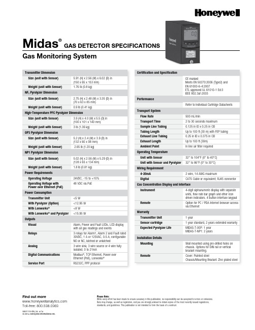
Midas®GAS DETECTOR SPECIFICATIONS Gas Monitoring SystemTransmitter DimensionSize (unit with Sensor) 5.91 (H) x 2.56 (W) x 6.02 (D) in(150 x 65 x 153 mm)Weight (unit with Sensor) 1.76 lb (0.8 kg)NF3 Pyrolyzer DimensionSize (unit with Sensor) 2.75 (H) x 2.48 (W) x 3.35 (D) in(70 x 63 x 85 mm)Weight (unit with Sensor)0.9 lb (0.41 kg)High-Temperature PFC Pyrolyzer DimensionSize (unit with Sensor) 3.9 (H) x 4.0 (W) x 5.5 (D) in(100 x 101 x 140 mm)Weight (unit with Sensor) 3 lb (1.36 kg)Power RequirementsOperating Voltage24VDC, -15 to +10%Operating Voltage withPower over Ethernet (PoE)48 VDC via PoEPower ConsumptionTransmitter Unit<5 WFind out more Toll-free: 800.538.0363SS01115-EN_V6 8/18© 2016 Honeywell International Inc.Please Note:While every effort has been made to ensure accuracy in this publication, no responsibility can be accepted for errors or omissions. Data may change, as well as legislation, and you are strongly advised to obtain copies of the most recently issued regulations, standards, and guidelines. This publication is not intended to form the basis of a contract.OP3 Pyrolyzer DimensionSize (unit with Sensor) 5.2 (H) x 2.4 (W) x 3.9 (D) in(132 x 60 x 98 mm)Weight (unit with Sensor) 2.65 lb (1.20 kg)NP1 Pyrolyzer DimensionSize (unit with Sensor) 5.02 (H) x 2.56 (W) x 5.29 (D) in(128 x 65 x 134 mm) Weight (unit with Sensor) 1.8 lb (0.81 kg)Find out more Toll-free: 800.538.0363SS01115-EN_V6 8/18© 2016 Honeywell International Inc.* M IDAS-E-LEL Cartridge carries a 2-year warranty but can be calibrated up to 5 years ** Gases require Midas PyrolyzerMidas detectors are not ETL approved for monitoring in or sampling from classified areas above 25% LELMidas Cartridge Detectable Gases Gas Name Chemical Formula Range Sensor Part Number Ammonia NH 39-100 ppm MIDAS-E-NH3ArsineAsH 318-200 ppb MIDAS-E-ASH Boron Trichloride BCl 30.72-8 ppm MIDAS-E-HCL Boron TrifluorideBF 30.72-8 ppm MIDAS-E-HFX Boron Trifluoride (Low Level)BF 30.18-2 ppm MIDAS-E-HFL Bromine Br 20.036-0.4 ppm MIDAS-E-BR2Carbon Dioxide CO 20.15-2.0%MIDAS-E-CO2Carbon Monoxide CO 9-100 ppm MIDAS-E-COX Chlorine Cl 20.18-2 ppm MIDAS-E-HAL Chlorine Dioxide ClO 20.036-0.4 ppm MIDAS-E-BR2Diborane B 2H 636-400 ppb MIDAS-E-B2H Dichlorosilane H 2Cl 2Si 0.72-8 ppm MIDAS-E-HCL Difluoromethane**CH 2F 216-240 ppm MIDAS-E-XCF Disilane Si 2H 6 1.8-20 ppm MIDAS-E-SHX Fluorine F 20.36-4 ppm MIDAS-E-HAL GermaneGeH 470-800 ppb MIDAS-E-ASH Hexafluorobutadiene**C 4F 63-40 ppm MIDAS-E-CFX Hydrogen (%LEL)H 2 6.5-100% LEL MIDAS-E-LEL*Hydrogen (ppm)H 290-1000 ppm MIDAS-E-H2X Hydrogen Bromide HBr 0.72-8 ppm MIDAS-E-HCL Hydrogen Chloride HCl 0.72-8 ppm MIDAS-E-HCL Hydrogen Cyanide HCN 1.8-20 ppm MIDAS-E-HCN Hydrogen FluorideHF 1.05-12 ppm MIDAS-E-HFX Hydrogen Fluoride (Low Level)HFL 0.18-2 ppm MIDAS-E-HFL Hydrogen Sulfide H 2S 3.6-40 ppm MIDAS-E-H2S Methane (%LEL)CH 4 6.5-100% LEL MIDAS-E-LEL*Methyl Fluoride**CH 3F 8-120 ppm MIDAS-E-XHF Nitric Oxide NO 9-100 ppm MIDAS-E-NOX Nitrogen Dioxide NO 2 1.05-12 ppm MIDAS-E-NO2Nitrogen Trifluoride**NF 3 3.6-40 ppm MIDAS-E-HFX for 00P, XHF for NP1Octofluorocyclopentene**C 5F 83-40 ppm MIDAS-E-XCF Oxygen O 20.2-25% v/v MIDAS-E-O2X OzoneO 30.065-0.7 ppm MIDAS-E-O3H Ozone (Low Level)O 30.036-0.4 ppm MIDAS-E-O3X Phosphine PH 3110-1200 ppb MIDAS-E-PH3SilaneSiH 4 1.8-20 ppm MIDAS-E-SHX Silane (Low Level)SiH 40.18-2 ppm MIDAS-E-SHL Sulfur DioxideSO 20.7-8 ppm MIDAS-E-SO2Tetra Ethyl Ortho Silicate TEOS 3.6-40 ppm MIDAS-E-TEO。
霍尼韦尔温控器DC10选型资料

1DC1010/1020/1030/1040 产品手册1DC1000系列通用控制器中文操作手册½öÓÃÓÚÆÀ¹À¡£°æȨËùÓÐ (c) by Foxit Software Company, 2004ÓÉ Foxit PDF Editor ±à¼-2DC1010/1020/1030/1040 PRODUCT MANUAL3DC1010/1020/1030/1040 产品手册34DC1010/1020/1030/1040 PRODUCT MANUAL5DC1010/1020/1030/1040 产品手册 5LCK=0001, 只进入LEVEL1并允许改变SP 值 LCK=0101, 除改变LCK 功能外,其它任何参数不能改变7DC1010/1020/1030/1040 产品手册79DC1010/1020/1030/1040 产品手册9假设SET8.3=1,SP值西安市将被改成PV值显示。
达到期望SP值的时间将被减少。
达到SP值的剩余时间显示在参数‘TMER’中。
在此,倒计数的时间是与PV值相关,而不是程序段。
11DC1010/1020/1030/1040 产品手册1112DC1010/1020/1030/1040 PRODUCT MANUAL13DC1010/1020/1030/1040 产品手册133) 结束功能如果ALD 设定为 17 (* 参看选择表), 此程序将在程序8或程序段16结束。
* 这样,在显示窗口中的 PV 和 END 将闪烁,报警继电器动作。
如果程序少于八个程序段,控制器就没有END 命令。
这样,请将下一程序段的 OUT 设定为0(out=0),程序就将在下一设定程序段结束。
霍尼韦尔行程开关 ZLS系列
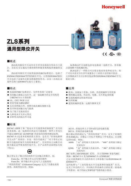
A600:“ A”表明最大交流功率,“600”表明最大额定 交流电压
Q300:“ Q”表明最大直流功率,“300”表明最大额定 直流电压
IEC 标准已被CENELEC 采用, 并且用EN60 来取代IEC。 例如:IEC947-5-1 变为EN60947-5-1 CENELEC 已定义两类限位开关的外形尺寸和参数于标准EN50041和 EN50047中。 这些标准与“工业用低电压开关装置和控制装置”有关,
ZLC EN50047 金属
-25~+80℃ <95%RH 10g/50g 0.05mm~2m/s 120次/分钟 <25m IP67 AC15 A600 DC13 Q300 2500V 107 5×10⁵
ZLD EN50047 塑料
-25~+80℃ <95%RH 10g/50g 0.05mm~2m/s 120次/分钟 <25m IP67 AC15 A600 DC13 Q300 2500V 107 5×10⁵
a、垂直运动的柱塞 b、线性运动的凸轮 2. 从图B 左上部标有A 的箭头处开始阅读。 3. 跟随黑色箭头和图中的黑条。黑条表明在两个端子间(端 子的数码标于图的左侧) 有电路连通,白条则表明没有电 路连通。
所有的尺寸的单位为mm
图A
FP 21 OT (max) 15
20 DT
OP 25
18.5±0.5
ZLS系10列7
■选型指南
ZLA 壳体类型 ZLA EN50041 金属外壳 ZLB EN50041 塑料外壳 ZLC EN50047 金属外壳 ZLD EN50047 塑料外壳 ZLE 三出线孔金属外壳 ZLF 两出线孔塑料外壳
Honeywell SX 系列基本微动开关 说明书

■ 特点◆ 低操作力,最大3 oz. (85 克)◆ 灵敏低差动行程最大为0.001英寸◆ 电源负载能力7A—镀银触点◆ 低能耗应用可选镀金触点◆ 分叉镀金触点可选,最大可靠性◆ 长机械寿命,一千万次操作,95%完好率◆ 温度范围 :-65o F~+250o F(-54℃~121℃)◆ 耐高温设计,可在+400o F (204℃)下工作100小时◆ 各种完整和附加驱动件可选◆ 数种端子类型可供选择◆ MIL-S-8805资质产品可选◆ UL 认证号#E12252, CSA 认证号#LR41372■ 断开1SX超小型基本开关■可选端子SX 开关提供数种端子类型可供选择。
T 型与T2型端子具有更简便的焊接配线附件。
H58型端子提供了简便的快速连接,并能与AMP.058英寸插座紧密结合。
针角端子可简便连接至印刷电路板。
■基本信息SX 超小型基本开关具有小精度尺寸,微型开关中的快速连接开关。
此类开关是节省空间和重量应用中十分理想的选择。
所有列表中的产品为镀银触点,特别注释的除外。
耐用铍铜弹簧耐磨酚醛底座与外壳延伸孔便于更精确的安装外壳安全接合至底座与Amp Inc.编号640024-1标准结合安装力矩圆头2-56UNC 438螺丝—最大为2英寸H391, H39290o 型针脚0,0 = mm 0.00 = inches单位表示:■针脚柱塞■订购指南(根据电气负载能力上升排列)Dim. Dwg. 图1(91SX39-T 和 93SX34-T 图2除外)■完整摆杆■订购指南特性:O.F.-动作力;R.F.-释放力;P.T.-预行程;O.T.-超行程;D.T.-差动行程;O.P.-操作位置Dim. Dwg. 图3Dim. Dwg. 图3Dim. Dwg. 图4Dim. Dwg. 图5Dim. Dwg. 图6311SX2-T(24.5mm)直摆杆5 Amps A 0.310.05 2.920.640.898.26±1.91313SX2-T 同上,带镀金触点1 Amp D0.310.052.920.640.898.26±1.91311SX3-T(24.5mm)直摆杆5 Amps A 0.200.03 4.700.61 1.527.75±2.92313SX3-T 同上,带镀金触点1 Amp D0.200.034.700.611.527.75±2.92311SX4-T(1.1mm)模拟滚轮摆杆5 Amps A 0.580.11 1.270.250.3814.15±0.91313SX4-T 同上,带镀金触点1 Amp D0.580.111.270.250.3814.15±0.91311SX5-T(11.7mm)模拟滚轮摆杆5 Amps A 0.310.05 2.670.560.8914.86±1.65313SX5-T 同上,带镀金触点1 Amp D0.310.052.670.560.8914.86±1.65■附加驱动件■订购指南特性:O.F.-动作力;R.F.-释放力;P.T.-预行程;O.T.-超行程;D.T.-差动行程;O.P.-操作位置; F.P.-自由位置*所有特性适用于如下所示1SX-T 装配的驱动件Dim. Dwg. 图7Dim. Dwg. 图8Dim. Dwg. 图9Dim. Dwg. 图9Dim. Dwg. 图10**开关与柱塞末端JX-40反转安装。
霍尼韦尔微动开关

11 基本微动开关 -V15
特性 : ◆ 结 构紧凑,具有微小触点间隙,快速动作、高灵敏度和 微小动作行程的特点 ◆长寿命,高可靠性 ◆拥有全球安规认证 ◆接线端子种类齐全 ◆动作力范围宽 7gf~400gf ◆多种温度等级 -25℃ ~+200℃ ◆配备各种形式操作柄 ◆ 广 泛应用于各种家用电器,电子设备,自动化设备,通 讯设备,汽车电子,仪器仪表,电动工具等领域 ◆ V15B 系列大于 3mm 触点间距, 寿命 50000 次安规认证。
Z 系列产品特性
大电流至 12(6)A,具备 1/4HP 马力负载认证,通行全球的安全认证,IP67 防 水保护可选。结构紧凑小巧,一致性好,适于各种控制领域选用!
不管你知道的我们是 MICRO SWITCH 还是 Honeywell, 正如你所知道的一样,超过半个世纪以来我们一直是业界强 大的领先者!创立于 1932 年的 MICRO SWITCH,是一家领跑追求电子器件小型化,高性能的公司。在它之前,没 有任何开关机构像它那样结实,高可靠性,能承担大电流,尺寸紧凑并且重量轻巧。今天,MICRO SWITCH 参与了 全球机械电子控制领域标准的制定。简单,可靠,优质,一切均由 MICRO SWITCH 持续演绎!
■ 应用
◆ 家用电器 ◆ 电子设备 ◆ 自动化设备 ◆ 通讯设备 ◆ 汽车电子 ◆ 仪器仪表 ◆ 电动工具等领域
■特性参数
工作速度 工作频率 绝缘电阻 接触电阻 耐电压 同极不相接端子间 带电金属零件与外壳之间,接线 端与易触及的不带电金属件之间 0.1mm~1m/s(与驱动方式有关) 机械 : 60 次 / 分钟 ; 电气 : 25 次 / 分钟 ≥ 100MΩ (500VDC) ≤ 30mΩ(初始值) AC1000V,50/60HZ,1 分钟 AC1500V,50/60HZ,1 分钟 10~55HZ,1.5mm 两倍振幅 破坏 : 动作力 >0.5N:1000m/s2(约 100G)max 动作力≤ 0.5N:400m/s2(约 40G)max 故障 : 动作力 >0.5N:200m/s2(约 20G)max. 动作力≤ 0.5N:100m/s2(约 10G)max. 机械 ≥ 10,000,000 次 或 1,000,000 次 电气 ≥ 50,000 次或 100,000 次(V15H10 系列) 约 6.2g(无操作柄)
美国霍尼韦尔限位开关
A113
Limit and Enclosed Switches
LSX Series
Weather-Sealed Explosion-Proof Switches
HOW TO ORDER
The order guide shows the option codes which are added to the LSX prefix to specify the operating head, body and circuitry, assembly modifications (if desired) and actuator type.
actuators. ɀ Field adjustability matches switch to
application. ɀ Momentary, maintained, random
sequence, or center neutral action. ɀ 10 amps continuous carry electrical
The example given below is LSXA3K-1A. This is an explosion-proof LSX switch with the standard side rotary momentary-action head (A), single-pole circuitry and 1⁄2 in. conduit opening (3K). Since no modification codes are listed, it is adjusted for both clockwise (CW) and counterclockwise (CCW)
Standard HDLS levers are used, but because of explosion-proof requirements, only nylon rollers or other non-sparking material can be selected. Plunger and cat whisker types listed in the LSX order guide are of non-sparking material.
霍尼韦尔楼宇自控电动阀门及执行器资料大全

霍尼韦尔总代理:深圳市松贤机电设备有限公司
目录:
霍尼韦尔楼宇自控产品订货渠道 ............................................................................2 冷/热水阀 (二通阀,PN16)................................................................................2
冷/热水阀 (二通阀,PN25)..............................................................................19
V5025A 系列冷/热水阀门(DN15—DN150).......................................................................19
Page 4 of 36
/
霍尼韦尔总代理:深圳市松贤机电设备有限公司
V5011P 系列冷/热水阀门(DN25—DN50)
应用 • V5011P 螺纹连接二通阀可用于蒸汽, 水和 50% 以上甘醇的 HVAC 应用,它 可用于二位或连续调节控制,不能用于燃气应用。
冷/热水阀 (三通阀,PN16)..............................................................................13
V5013P 系列冷/热水阀门(DN32—DN50) .........................................................................13 V5329A 系列冷/热水阀门(DN65—D80)(法兰连接) .....................................................15 V5050A 系列冷/热水阀门(DN100—D150)(PN16)............................................................17
霍尼韦尔传感器选型表【大全】
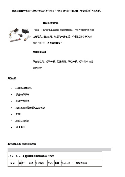
大家知道霍尼韦尔传感器选型表是怎样的吗?下面小编与您一同分享,希望对各位有所帮助。
霍尼韦尔传感器子学是一门光学和半导体电子学综合学科。
子元件制成的传感器性能可靠,经济实惠。
该系列产品包括:标准霍尼韦尔线发射二极管(IRED),传感器及其组件。
最佳使用环境:存在性检测、运动传感、位置编码、限位传感、运动物体的检测和计数。
典型应用:•印刷机和复印机•数据储存系统•运动控制系统•注射泵及其他无创式医疗设备•扫描•自动交易系统•计量系统高性能霍尼韦尔传感器选型表(1)1.5mm 金属封装霍尼韦尔传感器选型表型号类波长驱动发光强度发光/亮电Vce(sat) 上升规格书页码经济型霍尼韦尔传感器选型表扩展资料:霍尼韦尔传感器种类:霍尼韦尔的传感与控制分部以其优秀的产品质量和可靠性,以及不断的技术创新,不仅在北美、而且在全世界赢得了很高的声誉。
目前共有20多个系列近六万种产品,在全世界拥有三十万用户。
霍尼韦尔创立于1885年,从楼宇恒温控制装置开始,经过110余年的发展。
已经成为一个拥有120,000多名员工,年销售额达240亿多美元的全球化集团公司。
为工业楼宇设备和航天、航空应用提供各类传感器、控制产品和系统。
霍尼韦尔的传感与控制分部以其优秀的产品质量和可靠性,以及不断的技术创新,不仅在北美、而且在全世界赢得了很高的声誉。
目前共有20多个系列近六万种产品,在全世界拥有三十万用户。
霍尼韦尔传感与控制部件产品丰富,类别多样,适用于多个行业。
具体如下:1.汽车传感器采用Malcolm Baldrige和QS 9000 标准,并且不断满足客户的技术更新需要。
产品符合多种系统关键汽车应用的工业标准,这些标准包括:引擎管理、传动控制和发动机控制。
其解决方案能够提高燃油效率,降低污染,并使生产过程增加舒适性和便捷性。
典型应用:发动机管理系统主动式速度及位置传感器;传动管理系统主动式速度及位置传感器;主动式轮速传感器;驾驶舒适性,便捷性及马达控制应用位置传感器。
霍尼韦尔温控器DC10选型资料

1DC1010/1020/1030/1040 产品手册1DC1000系列通用控制器中文操作手册½öÓÃÓÚÆÀ¹À¡£°æȨËùÓÐ (c) by Foxit Software Company, 2004ÓÉ Foxit PDF Editor ±à¼-2DC1010/1020/1030/1040 PRODUCT MANUAL3DC1010/1020/1030/1040 产品手册34DC1010/1020/1030/1040 PRODUCT MANUAL5DC1010/1020/1030/1040 产品手册 5LCK=0001, 只进入LEVEL1并允许改变SP 值 LCK=0101, 除改变LCK 功能外,其它任何参数不能改变7DC1010/1020/1030/1040 产品手册79DC1010/1020/1030/1040 产品手册9假设SET8.3=1,SP值西安市将被改成PV值显示。
达到期望SP值的时间将被减少。
达到SP值的剩余时间显示在参数‘TMER’中。
在此,倒计数的时间是与PV值相关,而不是程序段。
11DC1010/1020/1030/1040 产品手册1112DC1010/1020/1030/1040 PRODUCT MANUAL13DC1010/1020/1030/1040 产品手册133) 结束功能如果ALD 设定为 17 (* 参看选择表), 此程序将在程序8或程序段16结束。
* 这样,在显示窗口中的 PV 和 END 将闪烁,报警继电器动作。
如果程序少于八个程序段,控制器就没有END 命令。
这样,请将下一程序段的 OUT 设定为0(out=0),程序就将在下一设定程序段结束。
Honeywell SS400 系列 开关型霍尔位置传感器 说明书
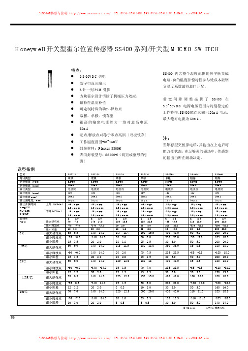
56Honeywell 开关型霍尔位置传感器SS400系列/开关型MICRO SWITCH选型指南型号SS411A SS413A SS441A SS443A SS449A SS461A SS466A 磁场类型 双极 双极 单极 单极 单极 锁存 锁存供电电压(VDC3.8-30 3.8-30 3.8-30 3.8-30 3.8-30 3.8-30 3.8-30 供电电流(max )10mA 10mA 10mA 10mA 10mA 10mA 10mA 输出类型 电流沉 电流沉 电流沉 电流沉 电流沉 电流沉 电流沉输出电压(max )40V 40V 40V 40V 40V 40V 40V 输出电流max*20mA 20mA 20mA 20mA 20mA 20mA 20mA 输出漏电流,max 10μA 10μA 10μA 10μA 10μA 10μA 10μA 上升 (10-90%) .05μs typ. 1.5μs max .05μs typ. 1.5μs max .05μs typ. 1.5μs max .05μs typ. 1.5μs max.05μs typ. 1.5μs max .05μs typ. 1.5μs max .05μs typ. 1.5μs max 输出开关时间 Vcc=12V RL=1.6K C=20pF 下降(90-10%) .15μs typ. 1.5μs max .15μs typ. 1.5μs max .15μs typ. 1.5μs max .15μs typ. 1.5μs max .15μs typ. 1.5μs max .15μs typ. 1.5μs max .15μs typ. 1.5μs max最大动作点 G mT 70 7.0 G mT 140 14.0 G mT 135 13.5 G mT 215 21.5 G mT 435 43.5 G mT 110 11.0 G mT 200 20.0 最小释放点-70 -7.0 -140 -14.0 20 2.0 80 8.0 210 21.0 -110 -11.0 -200 -20.0 磁特性-40℃最小回差15 1.5 20 2.0 15 1.5 25 2.5 30 3.0 50 5.0 200 20.0 最大动作点65 6.5 140 14.0 117 11.7 190 19.5 400 40.0 90 9.0 200 20.0 最小释放点 -65 -6.5 -140 14.0 20 2.0 80 8.0 230 23.0 -90 -9.0 185 18.5 0℃最小回差 15 1.5 20 2.0 18 1.8 25 2.5 30 3.0 50 5.0 200 20.0 最大动作点 60 6.0 140 14.0 115 11.5 180 18.0 390 39.0 85 8.5 180 18.0 最小释放点 -60 -6.0 140 14.0 20 2.0 75 7.5 235 23.5 -85 -8.5 -180 18.0 25℃最小回差15 1.5 20 2.0 20 2.0 25 2.5 30 3.0 50 5.0 200 20.0 最大动作点 60 6.0 140 14.0 120 12.0 180 18 400 40.0 85 8.5 180 18.0 最小释放点 -60 -6.0 -140 -14.0 15 1.5 70 7.0 215 21.5 -85 -8.5 -180 -18.0 85℃最小回差12 1.2 20 2.0 15 1.5 15 1.5 30 3.0 50 5.0 190 19.0 最大动作点 65 6.5 140 14.0 123 12.3 190 19.0 410 41.0 100 10.0 180 18.0 最小释放点 -65 6.5 -140 14.0 15 1.5 60 6.0 200 20.0 -100 10.0 -180 -18.0 125℃最小回差 12 1.2 20 2.0 8 0.8 10 1.0 30 3.0 50 5.0 160 16.0 最大动作点 70 7.0 140 14.0 125 12.5 200 20.0 420 42.0 110 11.0 185 18.5 最小释放点 -70 -7.0 -140 -14.0 10 1.0 55 5.5 185 18.5 -110 -11.0 -185 -18.5 150℃最小回差10 1.020 2.05 0.55 0.530 3.050 5.0140 14.0G=Gauss mT=milliTesla注:可订购安装在线带和卷带上的SS400,引脚上间距0.1”,每个卷带含3000个SS400传感器.所有SS400系列绝对输出电流值为50mA开关型霍尔位置传感器MICRO SWITCH SS400系列/开关型5758Honeywell 开关型霍尔位置传感器SS100系列/开关型,表面封装MICRO SWITCHG=GaussMT=milliTesla型号SS111A SS113A SS141A SS143A SS149A SS161A SS166A 磁性能 双极 双极 单极 单极 单极 锁存 锁存供电电压(VDC )3.8-30 3.8-30 3.8-30 3.8-30 3.8-30 3.8-30 3.8-30 供电电流(max )10mA 10mA 10mA 10mA 10mA 10mA 10mA 输出类型 电流沉 电流沉 电流沉 电流沉 电流沉 电流沉 电流沉输出电压(max )40V 40V 40V 40V 40V 40V 40V 输出电流max20mA 20mA 20mA 20mA 20mA 20mA 20mA 漏电流,max 10μA 10μA 10μA 10μA 10μA 10μA 10μA.1.5μs . 1.5μs . 1.5μs . 1.5μs .1.5μs . 1.5μs .1.5μs 输出开关时间上升下降.1.5μs 1.5μs .1.5μs 1.5μs 1.5μs .1.5μs .1.5μs 最大动作点 G mT 70 7.0 G mT 140 14.0 G mT 135 13.5 G mT 215 21.5 G mT 440 44.0 G mT 110 11.0 G mT 200 20.0 最小释放点-70 -7.0 -140 -14.0 20 2.0 80 8.0 210 21.0 -110 -11.0 -200 -20.0 磁特性-40℃最小回差15 1.5 20 2.0 15 1.5 25 2.5 30 3.0 50 5.0 200 0.0 最大动作点65 6.5 140 14.0 117 11.7 190 19.0 400 40.0 90 9.0 185 18.5 最小释放点 -65 -6.5 -140 14.0 20 2.0 80 8.0 230 23.0 -90 -9.0 -185 -18.5 0℃最小回差 15 1.5 20 2.0 18 1.8 25 2.5 30 3.0 50 5.0 200 20.0 最大动作点 60 6.0 140 14.0 115 11.5 180 18.0 390 39.0 85 8.5 180 18.0 最小释放点 -60 -6.0 -140 14.0 20 2.0 75 7.5 235 23.5 -85 -8.5 -180 18.0 25℃最小回差15 1.5 20 2.0 20 2.0 25 2.5 30 3.0 50 5.0 200 20.0 最大动作点 60 6.0 140 14.0 120 12.0 180 18 400 40.0 85 8.5 180 18.0 最小释放点 -60 -6.0 -140 -14.0 15 1.5 70 7.0 215 21.5 -85 -8.5 -180 -18.0 85℃最小回差12 1.2 20 2.0 15 1.5 15 1.5 30 3.0 50 5.0 190 19.0 最大动作点 65 6.5 140 14.0 123 12.3 190 19.0 410 41.0 100 10.0 180 18.0 最小释放点 -65 6.5 140 14.0 15 1.5 60 6.0 200 20.0 -100 10.0 -180 -18.0 125℃ 最小回差12 1.220 2.08 0.810 1.030 3.050 5.0160 16.0开关型霍尔位置传感器MICRO SWITCH SS100系列/开关型、表面封装地址:西安市高新区创新大厦MF5 网站:,E-mail:*******************.com5960SS94B1系列Honeywell 模拟霍尔位置传感器 MICRO SWITCH安装尺寸(仅供参考) 输出特性(仅供参考)特点:·单个电流沉或电流源输出 ·增强的温度稳定性 ·三针一列引脚·激光修正的薄膜和厚膜电阻减少了灵敏度变化并带温度 补偿内部结构图SS94B 选型指南规格SS94B1供电电压(VDC) 4.5-12工作性能@5VDC消耗电流(mA) 8typ.,11max 输出电流/Type 输出电压比率变化/电流沉或电流源输出1mA typ.,2mAmax输出电压范围 负高斯 正高斯 0.4V type Vs-0.4V typ 磁特性@25℃ 满量程 零点(偏置@0高斯) 灵敏度(mV/高斯) 线性度(%满量程) 5VDC(-67.0to+67.0mT,typ) 4.0V(-670to+670gauss,typ.)2.5±0.03V3.125±0.063 -0.5±0.5 温度误差(@25℃) 零点飘移(%/℃) 灵敏度飘移(%/℃)±0.03 ±0.0361Honeywell 模拟霍尔位置传感器 MICRO SWITCH特点:·单个电流沉或电流源输出 ·提高的温度稳定性 ·三针一列PCB 引脚·激光修正的薄膜和厚膜电阻减少了灵敏 度变化并带温度补偿·敏感磁场强度±100到±2500高斯SS94A 选型指南规格 SS94A1 SS94A1B SS94A1E SS94A1F SS94A2SS94A2C SS94A2D 主要特点通用 5VDC 工作低飘移高灵敏度噪声屏蔽++噪声屏蔽++噪声屏蔽++供电电压(VDC )*6.6-12.6 4.5-8.0 6.6-12.6 6.6-12.6 6.6-12.6 6.6-12.6 6.6-12.6消耗电流(mA )** 13typ 30max 8typ17.5max13typ30max 13typ 30max 13typ 30max 13typ 30max 13typ 30max 输出电流(mA) 电流沉或源 1max 1max1max1max1max1max1max反应时间(μsec ) 3typ 3typ 3typ 3typ 3typ 3typ 3typ 磁特性*** 满量程*625 Vs375 Vs625 Vs625 Vs625 Vs625 Vs625 Vs测量磁场范围(gauss )* -500-+500 -500-+500 -500-+500 -100-+100 -500-+500 -1000-+1000 -2500-+2500灵敏度(mV/gauss@25C ) 50±.1 1.875±1.00 5.0±.1 25.0±.5 5.0±0.1 2.0±0.05 1.00±0.02 线性度+(%span) -0.8typ -1.5max -0.8typ-1.5max-0.8typ-1.5max-0.8typ -1.5max-0.8typ -1.5max-0.8typ -1.5max-0.8typ -1.5max输出Vout(Ogauss@25C)*** 4.00±0.04V 2.50±0.05v 4.00±0.04v 1.00±0.08v 4.00±0.04v 4.00±0.04v 4.00±0.04v 温度误差(所有%S 以 25值为基准)* 零点(%/C ) 灵敏度(%/C )±.02 ±.02±0.25 ±0.25±.01 ±.02±.10 ±.02 .055±.02 ±.02±.0125 ±.02±.007 ±.02*-40℃~12℃**包括负载,典型在25℃/最大在-40℃***@Vs=5VDC 只限于SS94AIB/@Vs=8VDC 适用其余型号 +曲线始末端点直线法++陶瓷背面镀银与引脚电气连接 规定用2.2K Ω电阻除非另外标注零点电压(0高斯时电压)和灵敏度与供电电压比率变化62Honeywell 模拟霍尔位置传感器MICRO SWITCH特点:·体积小巧(0.16×0.118″) 低功耗—典型7mA 在5VDC ·电源沉或源线性输出·内含激光修正的薄膜电阻提供精确的灵 敏和温度补偿·工作温度范围-40~+150℃ ·可反应于正的或负的磁场·方块霍尔传感元件提供稳定的输出·Rail-to-Rail 性能可提供更有效的信号 以到达更高精度订货指南Vs=5.0V,T A =-40至+125℃(除非另外标明)指标 SS495A 标准 SS495A1 高精度 SS495A2*基本型供电电压(VDC ) 4.5-10.5 4.5-10.54.5-10.5 Typ. 7.0 7.07.0供电电流@25C(mA) Max. 8.50 8.5 8.5输出类型(电流沉 源)比率变化 比率变化 比率变化 输出电流(mA ) 典型电流沉 最小电流源 最小电流沉 最小电流沉 Vs >4.5V Vs >4.5V Vs >4.5V Vs >5.0V 1.5 1.0 0.6 1.0 1.5 1.0 0.6 1.01.5 1.0 0.6 1.0 磁特性@25C ,5VDC Typ Guass:-670-+670(-67-+67mT)磁场范围 Min Guass:-600-+600(-60-+67mT)Typ 0.2-(Vs-0.2)输出电压范围 Min 0.4-(Vs-0.4)零点电压(输出@0高斯、伏) 2.500±0.075 2.5±0.100 灵敏度(mV/G ) 3.125±0.125 3.125±0.094 3.125±0.156 Typ -1.0% -1.0%线性误差(%量程) Max -1.5% -1.5%温度误差 零点飘移(%/C ) 灵敏度飘移(%/C ) ≥25℃Max <25℃Max ±0.06% ±0.04%% +0.02%±0.03% +0.03%±0.03%±0.07% -0.02%+0.06%-0.01%+0.07%*散装,每包1000个表面安装型:加后缀S 如:SS495A-S 线带包装T1型:加后缀T1丝带包装P 型(表面安装):加后缀SP MilliTesla=Gauss ×10-1 公司由传感器销售部、仪表销售部、工程部和总务部四个部组成。
Honeywell HDLS 重载限位开关 说明书
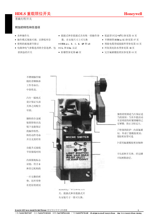
不锈钢操作轴上的烧结青铜轴承保证工作寿命长,操作中靠性高。
凸台一插座式头部设计保证头部和开关体之间配合紧密牢固。
独特的全金属传动装置即使在高温环境下也能保证一致的操作特性,比塑料传动件寿命更长,并且无需经常调整。
自提升式接线端子节省接线时间。
内部接地标志便于识别,符合OSHA 和其它机构的标准。
一片完整的密封平垫,比环形垫圈具有更好的密封性能。
无论单刀或双刀开关,拔插式或非拔插式开关,其执行杆的运动轨迹一致,可以互换。
前面固定,单刀和双刀开关、拔插式和非拔插式开头安装尺寸一致可互换。
独特的坚固适当片保证适当的扭矩: 当其不能活动时表明招待杆紧固螺母已足够紧,防止力矩过大。
双重轴密提供了特别的防护: 内部氟碳橡胶O型环密封,外部丁腈橡胶密封,也有全部氟碳橡胶密封型可选侧旋转式开关中采用氟碳橡胶密封轴和膜片。
坚固防腐的铸锌头部和开关体,经过磷化处理,具有环氧树脂涂层。
重载行程开关附加的特性和任选项•各种操作头•操作模式现场可调,以降低库存•便利的就地调节指示•电路和电气参数选项的全套选择,包括固态的开关•拔插式和非拔插式具有统一的操作参数,在安装尺寸上可互换• NEMA1,3,4,6,6P和13• UL和CSA认证•防爆型参见第63页•低温型(可达-40°C)参见第44页•不锈钢型(NEMA4X)参见第47页•预接电缆型或接插件型参见第44页•环氧填充防水型参见第45页•完全氟碳橡胶密封参见第44页LSH-低力矩、低差动行程型最小过行程68°,最大操作力矩0.19Nm 。
最大差动行程3°(单刀)或4°(双刀)。
LSL-顺序动作型 在每一方向上,两刀的动作相互间有一延时,最小过行程68°。
LSM-中央零点型一套触点在顺时针动作时工作,另一套触点在逆时针动作时工作。
最小过行程53°。
LSN-保持触点型操作在逆时针转动时被保持,在顺时针传动时被复位,反之亦然,最小过行程20°。
Honeywell ET系列手动开关 说明书

磁保持拨动开关ET系列模制弹性密封件保持线圈充惰性气的开关室玻璃珠接线端密封特点• 大多数产品达到MIL-S-5594质量标准• 耐环境的密封• 2和3位磁保持拨动动作• 标准,翼片和拉拨解锁拨杆• 按钮、引线和螺钉接线端• 温度范围: -85°F至+160°F(-65°C至+71°C)集管板工作原理ET手柄开关中的保持线圈替代了机械保持机构,将拨动开关维持在工作位置上。
拨动开关是通过断开线圈电路而释放的。
当保持线圈电路断开时,ET起到一个瞬时触点开关的作用。
当线圈被激励时(通过远程触点),将拨杆保持在工作位置上。
线圈去激会使得拨杆快速回到非工作位置。
拨杆也可以用手动方式释放(人控)。
注: 螺线管具有保存能力。
它不会将拨杠从非工作位置拉到工作位置。
两位。
上图展示了带有一个单刀双掷电路的ET运行顺序。
(1)手动闭合电路; (2)激励的电磁线圈保持开关电路于闭合状态;(3)远程控制断开电磁线圈电路,释放拨杆,并断开开关电路。
(在配有两个单刀双掷电路的ET中,当拨杆动作时,两个电路都转换)。
三位。
配有两个单刀双掷电路的ET具有从中心至两个方向上的磁保持能力。
当拨杆位于中心位置时,电路如上图所示。
当拨杆移向一极端位置时,开关(A)电路转换,而开关(B)电路保持不变。
在另一个极端位置上,开关(B)电路转换,而开关(A)电路保持不变。
电气额定值电流强度(A)海平面(密封) 65,000ft额定值代码电压电阻电感电动机电阻电感电动机A 28DC 4 2.5 4 4 2 4B 28DC 4 3 4 4 2.5 4C28DC7 2 - 5 1.5 -磁保持拨动开关 ET 系列拨杆标准 拉拨解锁接线端按钮 引线按压解锁 翼片螺钉拨杆型式标准-圆锥形无光饰面不锈钢 拉拨解锁-防止意外执行; 必须拉出以改变位置。
按压解锁-防止意外执行。
在拨至任一极端位置前,必须将拨杆按下约.100in 。
Honeywell MICRO SWITCH GLA限位开关系列说明书

DESCRIPTIONHoneywell’s MICRO SWITCH GLA Limit Switch Series is designed to globalEN50041 standards and well suited for worldwide applications. The modular design (heads/actuators, bodies, and contact blocks) of the limit switch allows for rapid response to meet customer applications. The rugged die-cast metal housing of the switch is ideal for indoor and outdoor applications where a degree of IP or NEMA enclosure sealing is required. Normally closed snap-action contacts and normally closed slow-action contacts are positive opening .VALUE TO CUSTOMERS•Easy to install and maintain • Rugged metal constructionFEATURES• Designed to EN50041 standard, 30 mm x 60 mm mounting• Available as a standard body or plug-in body with same footprint• Wide range of actuator heads and levers• Side rotary switches factory set for CW and CCW actuation; field adjustable for CW only or CCW only• Certified for global applications; UL/CSA (Americas/Canada), CE (Europe), CCC (Asia-Pacific)1• Conforms to IEC/EN 60947-5-1,EN 45545-2 (GLA/GLF Series), and EN 61373 (GLA)• Sealed to IP67 and NEMA/UL 1, 4, 12, and 13• Operating temperatures as low as -40 °C to 85 °C [-40 °F to 185 °F]• Multiple connectivity options to meet most applications: four different threaded conduits, micro-change connectors, mini-change connectors, Deutsch style 4-pin connector• One or two LED indicators available in switch body• Single pole double throw, two polesingle throw contact blocks (1NC/1NO, 2NC, 2NO) are galvanically (electrically) isolated (Zb) and designed with bifurcated contacts• Two pole double throw contact block (2NC/2NO) has each pole galvanically (electrically) isolated (Zb)• Normally closed contacts are positive style• Contact blocks are available as snap action or slow action• Analog output available with side rotary actuator• Mechanical life up to 15 million operationsGLA SERIESMICRO SWITCH Global Limit Switches002408Issue 5POTENTIAL APPLICATIONS• Aerial lifts, boom lifts• Automotive assembly lines and machining centers • Agriculture equipment • Conveyors• Doors and apertures • Material handling • Machine tools• Railroad locomotives and railroad signaling equipment • Transportation hubs • ValvesDIFFERENTIATION• Side rotary actuator incorporates dual bearing design which prevents side loading during operation• Removable contact block allows for ease of wiring• Modular design of limit switch (heads/actuators, bodies, and contact blocks) allows for rapid customization and delivery• Optional 1 LED or 2 LED pilot lights in limit switch front cover to indicate voltage present to switch and/or switch actuated• Specialty contact options, sequential (2-step style) action, and center neutral actionPORTFOLIO1CCC certification is not available on the GL Series Switches sold within Europe, Middle East,*Normally closed (NC) contacts are positive opening except for the center neutral limit switches 1CCC certification is not available on the GL Series Switches sold within Europe, Middle East, and Africa. Option for CCC certification in these regions is availableupon request.Figure 1. Product NomenclatureGLSwitch Type GL Series Global LimitSwitch01Basic SwitchE7BActuators or Levers* Body Style(EN50041)AConduitA AHeads**NOTE: Basic switch codes 02 and 12 may only be usedwith body styles B and G.* Note: When conduit style G1/2 (PF1/2) is required, change the 4th digit in the catalog listing to the letter D. For example, GLAfor G1/2 conduit. When conduit style PG13,5 is required, change the 4th digit in the cagalog listing to the letter B. For example, GLA A01A1A would change to GLA B01A1A for PG13,5 conduit.** Positive opening occurs.† Contacts 11-12, 13-14 operate in CCW direction. ‡ Contacts 21-22, 23-24 operate in CW direction.for G1/2 conduit. When conduit style PG13,5 is required, change the 4th digit in the cagalog listing to the letter B. For example, GLA A01A1A would change to GLA B01A1A for PG13,5 conduit.** Positive opening occurs.† Contacts 11-12, 13-14 operate in CCW direction. ‡ Contacts 21-22, 23-24 operate in CW direction.for G1/2 conduit. When conduit style PG13,5 is required, change the 4th digit in the cagalog listing to the letter B. For example, GLA A01A1A would change to GLA B01A1A for PG13,5 conduit.** Positive opening occurs. † Contacts 11-12, 13-14 operate in CCW direction. ‡ Contacts 21-22, 23-24 operate in CW direction.* Note: When conduit style G1/2 (PF1/2) is required, change the 4th digit in the catalog listing to the letter D. For example, GLA A01A1A would change to GLA D01A1A for G1/2 conduit. When conduit style PG13,5 is required, change the 4th digit in the cagalog listing to the letter B. For example, GLA A01A1A would change toGLA B01A1A for PG13,5 conduit.** Positive opening occurs.* Note: When conduit style G1/2 (PF1/2) is required, change the 4th digit in the catalog listing to the letter D. For example, GLA A01A1A would change to GLA D01A1A for G1/2 conduit. When conduit style PG13,5 is required, change the 4th digit in the cagalog listing to the letter B. For example, GLA A01A1A would change toGLA B01A1A for PG13,5 conduit.** Positive opening occurs.TABLE 4. MICRO SWITCH GLA SERIES PLUNGER ORDER GUIDEfor G1/2 conduit. When conduit style PG13,5 is required, change the 4th digit in the cagalog listing to the letter B. For example, GLA A01A1A would change toGLA B01A1A for PG13,5 conduit.** Positive opening occurs.for G1/2 conduit. When conduit style PG13,5 is required, change the 4th digit in the cagalog listing to the letter B. For example, GLA A01A1A would change to GLA B01A1A for PG13,5 conduit..** Positive opening occurs.* Note: When conduit style G1/2 (PF1/2) is required, change the 4th digit in the catalog listing to the letter D. For example, GLA A01A1A would change to GLA D01A1A for G1/2 conduit. When conduit style PG13,5 is required, change the 4th digit in the cagalog listing to the letter B. For example, GLA A01A1A would change toGLA B01A1A for PG13,5 conduit.* Note: When conduit style G1/2 (PF1/2) is required, change the 4th digit in the catalog listing to the letter D. For example, GLA A01A1A would change to GLA D01A1A for G1/2 conduit. When conduit style PG13,5 is required, change the 4th digit in the cagalog listing to the letter B. For example, GLA A01A1A would change toGLA B01A1A for PG13,5 conduit.* Note: When conduit style G1/2 (PF1/2) is required, change the 4th digit in the catalog listing to the letter D. For example, GLA A01A1A would change to GLA D01A1A for G1/2 conduit. When conduit style PG13,5 is required, change the 4th digit in the cagalog listing to the letter B. For example, GLA A01A1A would change to GLA B01A1A for PG13,5 conduit.** Positive opening occurs.* Note: When conduit style G1/2 (PF1/2) is required, change the 4th digit in the catalog listing to the letter D. For example, GLA A01A1A would change to GLA D01A1A for G1/2 conduit. When conduit style PG13,5 is required, change the 4th digit in the cagalog listing to the letter B. For example, GLA A01A1A would change toGLA B01A1A for PG13,5 conduit.** Positive opening occurs.TABLE 10. MICRO SWITCH GLB SERIES TOP ROLLER LEVER ORDER GUIDE (PLUG-IN BODY)* Note: When conduit style G1/2 (PF1/2) is required, change the 4th digit in the catalog listing to the letter D. For example, GLA A01A1A would change to GLA D01A1A for G1/2 conduit. When conduit style PG13,5 is required, change the 4th digit in the cagalog listing to the letter B. For example, GLA A01A1A would change toGLA B01A1A for PG13,5 conduit.** Positive opening occurs.* Note: When conduit style G1/2 (PF1/2) is required, change the 4th digit in the catalog listing to the letter D. For example, GLA A01A1A would change to GLA D01A1A for G1/2 conduit. When conduit style PG13,5 is required, change the 4th digit in the cagalog listing to the letter B. For example, GLA A01A1A would change toGLA B01A1A for PG13,5 conduit..Figure 2. Fixed Lever, Side Rotary Switch - Non-plug-in Body Style, GLZ51 Style Lever, and GLA BodyLEVERROLLER MATL X DIM Y DIM Z DIMGLZ51ANYLON19,1.7555,92.206,4.25GLZ51B STEEL 19,1.7555,92.206,4.25GLZ51C NYLON 24,51.0059,12.3312,7.50GLZ51Y RUBBER 50,01.9766,12.6010,0.39GLZ51T STAINLESS STEEL 19.1.7556.82.248.8.345(catalog listing)Figure 3. Fixed Lever, Side Rotary Switch - Plug-in Body Style, GLZ51 Style Lever, and GLB BodyProduct Dimensions: GLA SeriesLEVERROLLER MATL X DIM Y DIM Z DIM GLZ52A NYLON 19,1.7565,92.596,4.25GLZ52B STEEL 19,1.7565,92.596,4.25GLZ52D NYLON 38,11.565,92.596,4.25GLZ52ENYLON19,1.7579,373.12533,071.300GLZ52W RUBBER 40,01.671,52.8112,7.5GLZ52YRUBBER50,01.9768,82.7110,0.39Figure 4. Adjustable Lever Dimensions, GLZ52Figure 5. Aluminum Rod Lever Dimensions, GLZ54Figure 7. Roller Plunger DimensionsFigure 6. Pin Plunger DimensionsTop Pin PlungerRefer to Figure 2 or 3 for other dimensionsTop Roller PlungerRefer to Figure 2 or 3 for other dimensionsFigure 8. Roller Lever DimensionsRefer to Figure 2 or 3 for other dimensionsHead Code: E • WOBBLE AND CAT WHISKER ACTUATOR DIMENSIONSFigure 9. Coil Actuator Figure 10. Plastic Rod and Flexible Cable5.5 inches (stainlesssteel)6.5 inches (stainless steel)7.5 inches (stainless steel)Figure 11. Cat Whisker WobblesRefer to Figure 2 or 3 for other dimensions Refer to Figure 2 or 3 for other dimensionsRefer to Figure 2 or 3 for other dimensionsAPPLICATION INFORMATIONSide Rotary AssembliesThe side rotary assemblies incorporate a feature for adjusting the free position of the side rotary lever. The EN 50041 body style allows infinite adjustment and reclamp. See the following dia-grams for details of the mechanism in each case.Figure 12. Standard EN 50041 Body StyleThere are two lever mounting options:1. By fully seating the lever in one of the four 90° detent posi-tions on the shaft hub which provides positive lever retention.2. By mounting the lever on the serrated portion of the shaft (which enables the lever to be mounted in any position).To change the rotary lever’s free position:1. Use a 3 mm hex Allen wrench to loosen the Allen screw, as shown in Figure 13, below.2. Back off the lever 2 mm and move it to the desired free position.3. Retighten the Allen screw.4. Check to see if the free position is satisfactory for the application.5. Repeat the adjustment procedure if necessary.A teller tab located at the bottom of the lever (see diagram below)helps prevent lever slippage. It enables the installer to detect the correct tightening torque. When this tab cannot be moved, the Allen screw has been tightened properly.Figure 13. Allen Screw and Teller Tab LocationEN 50041 Side Rotary Actuator Direction AdjustmentAs furnished, GLS rotary switches will operate when the lever is rotated from either the left or right. They can be field modified to operate in one direction only (Clockwise CW; Counter clockwise CCW) by following these steps:1. Carefully remove the complete head assembly.2. Turn the head assembly upside down as shown in Figure 14.3. Pull the plunger mechanism out and rotate it through 90° increments until the alignment tab points to the desired func-tion (CW, CCW, or CW and CCW).4. Push plunger mechanism in.5. Reassemble the head assembly and re-test the switch in its application.Figure 14. Actuation AdjustmentREPLACEMENT INSTRUCTIONSAll levers for side rotary assemblies are available as replacment parts. All basics, except the plug-in, can be replaced. All EN 50041 heads can be replaced. The replacement procedures for these components are straightforward in nature.Side Rotary LeversRemove the lever from the product being replaced. On EN 50041product this is achieved by loosening the Allen screw holding the lever on the shaft. Replace the lever and tighten the Allen screw or combination screw. Re-test the switch in its application.HeadsAll EN 50041 style switch heads can be removed and replaced.1. Remove the head by unscrewing the four retaining screws on the head assembly.2. Ensure replacement part is identical to one being removed.3. Re-test the assembly and ensure correct operation.Basic Switches Non-plug-inBasic switches can be removed and replaced by following this procedure:1. Remove the cover from the body.2. Before disconnecting the switch wiring, carefully note the wir-ing arrangement for your application, particularly the safety ground connection.3. Remove the basic switch retaining screw.4. Remove the basic switch and install the replacement basic switch.5. Use the retaining screw to install the new basic switch – ensure that it is correctly seated in the switch body.6. Wire the switch terminals as before.7. Before replacing the cover – ensure that the basic switch wires are not twisted or otherwise lifted from the basic switch (to prevent them from becoming trapped when the cover is replaced).8. Test the switch in its application.Figure 15. Retaining screw locationBasic SwitchesPlug-in EN50041 body styleThe switch enclosure portion of this two-piece body style plugs into a pre-wired terminal block mounted in the application. Replacement is accomplished by unplugging the old switch enclosure and plugging-in a new switch enclosure (basics are permanently staked in the switch enclosure).LED WIRINGThe GLF, GLG, and GLH versions of GLS (EN 50041) come complete with LED indicators. These indicators can be wired in a variety of ways. Operation can indicate switch free or switch operated depending on the wiring arrangement employed. The table below indicates the body styles and indicators offered.Table 12. LED SeriesBody Function SpecificationGLF 1 LED 12 Æ 250 Vac and dc less than 1.5 mA draw GLG 1 LED plug-in 12 Æ 250 Vac and dc less than 1.5 mA draw GLH2 LED18 Æ 30 Vdc 7 mA typ. current drawThe following wiring diagrams show possible configurations that can be used for the LEDs. Combinations of these arrange-ments can be used where the dual LED versions of GLS are employed.Figure 16. Wiring Diagram 1In Figure 16, Wiring Diagram 1, the basic switch contact isopen. The current for the LED can flow through the LED (via the load) and the LED illuminates.Figure 17. Wiring Diagram 2In Figure 17, Wiring Diagram 2, the basic switch contact is closed. The current for the LED cannot flow through the LED and the LED will not illuminate.Figure 18. Wiring Diagram 3In Figure 18, Wiring Diagram 3, regardless of the position of the basic switch, the current for the LED can flow through the LED and the LED will illuminate indicating power available.Figure 19. Wiring Diagram 4In Figure 19, Wiring Diagram 4, when the load is energized the LED will illuminate. The above examples suggest options with these versions of GLS. The LED pilot lights should be treated as ’’for indication only’’ devices.Note:While every effort is made to ensure that the above guidelines areaccurate, no responsibility can be accepted for failure to apply good engineering practice to machinery design and use of Honeywell products. Never apply any of the procedures outlined above on live circuits. Ensure that testing of changes is carried out with no risk of injury during tests. These guidelines are produced to help our customers make the right choices in applying our Limit Switches to general applications. Contact your local Honeywell representative if you have any difficulties.Fixed length yoke lever; 38,1 mm [1.5in] radiusFixed length offset lever; 38,1 mm [1.5 in] radiusADDITIONAL MATERIALSThe following associated literature is available at /ast:• Product range guide • Product application-specific information – Sensors and switches in front loaders– Sensors and switches in mobile cranes–Sensors and switches in oil rig applicationsWARRANTY/REMEDYHoneywell warrants goods of itsmanufacture as being free of defective materials and faulty workmanship during the applicable warranty period. Honeywell’s standard product warranty applies unless agreed to otherwise by Honeywell in writing; please refer to your order acknowledgment or consult your local sales office for specific warranty details. If warranted goods are returned to Honeywell during the period ofcoverage, Honeywell will repair or replace, at its option, without charge those items that Honeywell, in its sole discretion,finds defective. The foregoing is buyer’s sole remedy and is in lieu of all other warranties, expressed or implied, including those of merchantability and fitness for a particular purpose. In no event shall Honeywell be liable for consequential, special, or indirect damages.While Honeywell may provide application assistance personally, through ourliterature and the Honeywell web site, it is buyer’s sole responsibility to determine the suitability of the product in the application.Specifications may change without notice. The information we supply isbelieved to be accurate and reliable as of this writing. However, Honeywell assumes no responsibility for its use.002408-5-EN | 5 | 04/21© 2021 Honeywell International Inc. All rights reserved.m WARNINGIMPROPER INSTALLATION• Consult with local safety agenciesand their requirements whendesigning a machine-control link, interface and all control elements that affect safety.• Strictly adhere to all installationinstructions. Failure to comply with theseinstructions could result in death or serious injury.m WARNINGMISUSE OFDOCUMENTATION•The information presented in this product sheet is for reference only. Do not use this document as a product installation guide.•Complete installation, operation, and maintenance information is provided in the instructions supplied with each product.Failure to comply with theseinstructions could result in death or serious injury.HoneywellAdvanced Sensing Technologies 830 East Arapaho Road Richardson, TX /astFOR MORE INFORMATIONHoneywell Advanced Sensing Technolo-gies services its customers through a worldwide network of sales offices and distributors. For application assistance, current specifications, pricing, or the nearest Authorized Distributor, visit /ast or call:USA/Canada +302 613 4491Latin America +1 305 805 8188Europe +44 1344 238258Japan +81 (0) 3-6730-7152Singapore +65 6355 2828Greater China+86 4006396841。
- 1、下载文档前请自行甄别文档内容的完整性,平台不提供额外的编辑、内容补充、找答案等附加服务。
- 2、"仅部分预览"的文档,不可在线预览部分如存在完整性等问题,可反馈申请退款(可完整预览的文档不适用该条件!)。
- 3、如文档侵犯您的权益,请联系客服反馈,我们会尽快为您处理(人工客服工作时间:9:00-18:30)。
电气参数 AC:
DC:
10A thermal: SPTD (NEMA A600), DPTD (NEMA B600) 细节请参考规格书
10A thermal: SPTD (NEMA A600), DPTD (NEMA B600) 细节请参考规格书
10A thermal: SPTD (NEMA A600), DPTD (NEMA B600) 细节请参考规格书
密封 温度范围
电气参数
高: 低:
AC:
DC:
电路 认证机构 典型应用
NEMA 1,3,4,13
71¼C (160¼F) -32¼C (-25¼F) 5A or 11A, 125 VAC 细节请参考规格书
SPDT 特种机械 农业设备 运土设备
与MICRO SWITCH其他 类别的开关价格比较 (-到+) *更多数据参考规格书
GLS MIN-DIN
3.03(77)H, 1.201(30,5)W , 1.18(30)L
侧旋转 顶部柱塞 ¥平面 ¥滚轮 顶部滚轮杠杆 Wobble
GLS DIN
4.05(102,9)H, 1.65(42)W , 1.65(42)L
侧旋转 ¥标准 ¥中点中性 ¥次序性 顶部柱塞 ¥平面 ¥滚轮 顶部滚轮杠杆 Wobble
6
NEMA 1,3,4,12*
NEMA 1,3,4,13*
71¼C (160¼F) -32¼C (-25¼F)
71¼C (160¼F) -32¼C (-25¼F)
SPDT: 15A - 125, 250, 480 V AC DPDT: 10A - 125, 250 V AC SPDT: 0.5A - 125VDC: 0.25A - 250VDC DPDT: 0.3A - 125VDC: 0.15A - 250VDC
顶部柱塞 ¥平面 ¥滚轮 ¥叉形滚轮 连续 w/reset柱塞 ¥平面柱塞 ¥滚轮柱塞 ¥滚轮杠杆 杠杆驱动 ¥滚轮 ¥单向滚轮 ¥手动 ¥微力转杆 Wobble
密封或非密封执行元件。坚固的 涂粉外壳可以防切割防腐蚀。瞬 态接触或连续接触。侧面或凸边 安装。替换部件可选。可插拔的 端子外壳使绕线简单。内部基本 开关结构提供更高的重复性。低 温版本可选。可选的金质触点。 内部接地螺钉。
赝品永远不能企及正品
3
重载限位开关
封装尺寸 执行元件s
特殊特性
标准HDLS
全密封HDLS
不锈钢HDLS
SPDT: 4.2H,2.4W ,1.6L, DPDT: 4.7H,2.4W ,1.9L SPDT: 4.2H,2.4W ,1.6L, DPDT: 4.7H,2.4W ,1.9L 4.9H, 2.4W, 1.9L
BAF1
3.2H, 1.3W, 4.0L
顶部柱塞 ¥平面 ¥滚轮 连续 w/reset柱塞 杠杆驱动 ¥滚轮 ¥单向滚轮 ¥手动 Wobble
为wash down应用设计的密封结 构。坚固的三出线孔铸铝外壳。 瞬态接触或连续接触。左或者右 执行元件。可插拔的端子外壳使 绕线和内部开关替换都简单易行 。内部接地螺钉。
传感与控制
选择真正的
MICRO SWITCH
Global Limits 重载限位开关 中载限位开关 紧凑结构限位开关 恶劣环境限位开关
全程限位开关
封装尺寸 执行元件
特殊特性
SZL-VL
3.8(96,5)H, 1.51(39)W , 1.10(28)L
侧旋转 ¥固定长度滚轮杠杆 ¥可调长度杠杆 顶部柱塞 ¥平面 ¥滚轮 ¥叉形滚轮 Wobble Wobble cat whisker
电路
SPDT double break, DPDT double break SPDT double break, DPDT double break SPDT, DPDT double break
认证机构 典型应用
UL, CSA, CE
机床设备 材料加工 包装机 出版业 纸浆和造纸机械 播种机械 PLC界面
7
紧凑结构限位开关
封装尺寸 执行元件
特殊特性
914CE/924CE
2.1H, .6W, 1.6L
侧旋转 顶部柱塞 ¥ 平面
¥ 套管安装 ¥ 长度可调节 ¥ Booted ¥ 滚轮 ¥ 内联 ¥ 十字 ¥ 套管安装 ¥ Booted ¥ 球面柱塞 按钮 W obble
SPDT: 20A - 125, 250, 480 V AC DPDT: 10A - 125, 250 V AC SPDT: 0.5A - 125VDC: 0.25A - 250VDC DPDT: 0.3A - 125VDC: 0.15A - 250VDC
SPDT, DPDT
SPDT, DPDT
UL, CSA, CE
10A thermal: SPDT (NEMA A600), DPDT (NEMA A300) 10A thermal: SPDT and DPDT (NEMA Q300)
SPDT 快速动作,双断 SPDT 慢速动作,双断 先断后合 SPDT 慢速动作,双断 先合后断 DPDT 快速动作,双断
UL, CSA, 和CE EN 50047
紧凑尺寸,灵活的电缆可以 进行简单快速的端口绕线。 坚固塑料/金属压铸外壳。镀 金银质触点。
根据IEC标准设计界,具有全程适应 性。AII NC触点正向打开。Field adjustable head may be positioned at 90¼ increment。 侧旋转模型可以顺时针和/或逆时针 旋转驱动。双绝缘塑料外壳。三出 线孔金属外壳。十字触点SPDT配置 。
顶旋转 旋转(各种杠杆) ¥瞬态 ¥连续 ¥瞬态中心中性 ¥瞬态有序 顶部柱塞 ¥平面 ¥长度可调节 ¥杠杆 侧面柱塞 ¥平面 ¥滚轮 ¥连续 Wobble
顶旋转 侧旋转(各种杠杆) ¥瞬态 ¥连续 ¥瞬态中心中性 ¥瞬态有序 顶部柱塞 ¥平面 ¥长度可调节 ¥杠杆 侧面柱塞 ¥平面 ¥长度可调节 ¥杠杆 ¥连续 Wobble
UL, CE, 加拿大UL认证
机床设备 材料加工 包装机 电子组装设备 博弈器材 注模设备
2
IP66 金属外壳 : 1,4,12,13 塑料外壳 : 1,12,13
IP 67 1,3,4,12,13
85¼ C (185¼ F) -25¼ C (-13¼ F)
85¼ C (185¼ F) -25¼ C (-13¼ F)
根据IEC标准设计界,具有全球适应 性。AII NC触点正向打开。金属压 铸外壳。Field adjustable head may be positioned at 90¼ increment。侧旋转模型可以顺时针 和/或逆时针旋转驱动。金质触点。 十字触点SPDT配置。插入式和非插 入式类型。
机床设备 材料加工 包装机 纺织机械 建筑机械设备 PLC界面
10A thermal: SPDT (NEMA A600), DPDT (NEMA A300) 10A thermal: SPDT and DPDT (NEMA Q300)
SPDT 快速动作,双断 SPDT 慢速动作,双断 先断后合 SPDT 慢速动作,双断 先合后断 DPDT 快速动作,双断
UL, CSA, CE
食品和饮料业 运输设备 自动化机床和传输带 纸浆和造纸设备
UL, CSA, CE
船舶和码头 发电厂 Gaustic废物处理 采矿 食品和饮料业 腐蚀阀门位置 电气装配
与MICRO SWITCH其他 类别的开关价格比较 (-到+)
*更多数据参考规格书
w w w. h o n e y we l l . c o m / s e n s i n g
5
中载限位开关
封装尺寸 执行元件
特殊特性
BF 2.7H, 1.2W, 2.9L 顶部平面柱塞 杠杆驱动 ¥转杆 ¥滚轮 Wobble
坚固的塑料外壳无需接地螺 钉。内部超大开关腔设计使 得绕线简单。带有压力板的 端子螺钉使得不管安装前还 是安装后进行绕线都非常简 单。
E6/V6
2.7H, 1.0W, 3.0L
UL, CSA
包装设备 特种机械 纺织机械 传送带 建筑机械 农场设备 印刷业机械 桥式吊车和吊升机械
包装设备 特种机械 农场机械 传送带 桥式吊车和吊升机械
w w w. h o n e y we l l . c o m / s e n s i n g
我们向您承诺:按时送货
送货误时意味着浪费时间增加成本。 作为一个全球性的MICRO SWITCH品牌 ,我们必须提供一个平稳,不间断的 物流过程来提高您的生产效率,节省 您的金钱,以及保持您的信誉。我们 可以帮助您在生产过程中减少那些难 以避免的产品短缺造成的亏损。通过 加强纪律,例如学习制造和总供给的 链式关系,我们可以自信我们的送货 及时率达到99,9%。如果按时得到开关 对您来说非常重要,那么就请选择霍 尼韦尔传感与控制。我们将使之成为 您最大的优势。
1,3,4,4X,6,6P ,12,13
温度范围 高: 121¼ C(250¼ F)* 低: -12¼ C(10¼ F)/-40¼ C (-40¼ F)
121¼ C (250¼ F) -12¼ C (10¼ F)/-40¼ C (-40¼ F)
121¼ C (250¼ F) -12¼ C (10¼ F )/-40¼ C (-40¼ F)
密封
IEC: NEMA:
温度范围 高: 低:
电气参数 AC:
DC:
电路
IP64
60¼ C (140¼ F) -20¼ C (-4¼ F) 5A Resistive -125, 250 V AC 0.4A Resistive -125 VDC SPD 双断
认证机构 典型应用
与MICRO SWITCH其他 类别的开关价格比较 (-到+) *更多数据参考规格书
