机械加工表面质量--(外文翻译)(可编辑)
机械制造技术:机械加工表面质量
工件材料性质
•太硬、太软、韧性、导热性差
↑→ Ra↓
7
2、表面粗糙度的控制
8
3、表面物理力学性能的控制
影响显微硬度因素
表面物理力学性能
影响残余应力因素
影响金相组织变化 因素
•切削热
9
冷作硬化
机械加工时,工件表面层金属受到切削力的作用产生强烈的塑性变形,使晶格 扭曲,晶粒间产生剪切滑移,晶粒被拉长、纤维化甚至碎化,从而使表面层的强度和 硬度增加,这种现象称为加工硬化,又称冷作硬化和强化。
高速(35~ 50 m/s)打击被加 工零件表面
14
4、表面强化工艺
滚压加工
利用淬硬的滚压工具(滚轮或滚 珠)在常温下对工件表面施加压力, 使其产生塑性变形,工件表面上原 有的波峰被填充到相邻的波谷中, 以减小表面粗糙度值,并使表面产 生冷硬层和残余压应力,从而提高 零件的承裁能力和疲劳强度。
波峰被填充到 相邻的波谷中
金相组织变化 机械加工过积中,在工件的加工区及其邻近的区域,温度会急剧升高,当温度
超过工件材料金相组织变化的临界点,就会发生金相组织变化。
磨削热是造成金相组织变化的根源,故改善磨削烧伤可有两个途径:
尽可能减少磨削热的产生; 改善冷却条件,尽量使产生的热量少传入工件。
12
4、表面强化工艺
表面强化工艺是指通过冷压加工方法使表面层金属发生冷态塑性变形, 以降低表面粗糙度值,提高表面硬度,并在表面层产生残余压应力。这 种方法工艺简单、成本低廉,应用广泛。
机械加工 表面质量
表面的几何特征
表面层物理力学、
化学性能
Байду номын сангаас
(1)表面粗糙度 (2)表面波度 (3)纹理方向
外文翻译-机械加工表面质量

机械专业外语文献翻译系别专业班级学生姓名学号日期The Surface Quantity While Machine ProcessesA.the machine processes the surface quantity to use the influence of the function to the machine(A)The surface quantity to bear to whet the sexual influence1. Rough degree of surface to bear to whet the sexual influenceThe rough degree of surface is very big to the influence that the spare parts surface wear away.Say a value of surface generally more small, it wears away sex more good.But rough degree of surface the value is too small, lubricant not easy storage, contact of the noodles easy occurrence the member glues to connect, wearing away to increase on the contrary.Therefore, the rough degree that contact face have a the best value, it is worth to have something to do with the work circumstance of the spare parts, working to carry the lotus enlargement, wore away the quantity aggrandizement in the early years, rough degree of surface the best value also enlargement.2. The surface is cold to make to harden to bear to whet the sexual influenceProcess the surface cold to make to harden to make rub the vice- surface layer the metals of show minute details the degree of hardness exaltation, past can make bear to whet the sex exaltation generally.But is also not cold to make to harden the degree more high, bear to whet sex more high, this is because excessively cold make to harden and will cause the excesssive loose of the metals organization loose, even appear the crack and surface layer metals peeling off, make bear to whet sex to descend.(B)The surface influence of the quantity upon the tired strengthThe tired breakage that metals produce after be subjected to hand over to change to carry the lotus function usually takes place under the cold and hard layer of the spare parts surface and surfaces, therefore the surface quantity of the spare parts affects to the tired strength very greatly.1. The surface influence of the rough degree upon the tired strengthAt hand over to change to carry the lotus function under, the surface part of the cave valley of the rough degree causes easily should the dint concentration, produce the tired crack.A value of surface is more big, the crackle of the surface is more deep, the crackle bottom radius is more small, the anti- tired breakage bottom ability is more bad.2. Remaining dint, cold make to harden to the influence of the tired strengthRemaining dint is very big to the spare parts influence of the tired strength.The surface layer remaining pull should the dint will make tired crack extend, accelerating the tired breakage;But the surface layer remaining should the dint can keep tired crack from expand, defer tired breakage of creation.Surface the cold and hard general companion contain remaining of should the creation of the dint, can keep the crack creation from combine the arrestment already has the crack to expand, to raise the tired strength beneficial.(C) the surface quantity to bear the eclipse influenceThe spare parts bears the eclipse to be decided by the rough degree of surface to a large extent.A value of surface is more big, accumulating the causticity material in the then cave valley more many.The anti- eclipse is more bad.Remaining of the surface layer pull should the dint will produce should the dint decay to open the rift , lower the spare parts to bear to whet sex, but Residual stress press should the dint then can prevent°from should dint decay open the rift .(D)The surface quantity to match with the influence of the quantityA size for be worth of surface will affect the match quantity of the match surface.Match with for the cleft, a value conference make wear away the enlargement, the cleft enlarge, the match property that break the request.For lead the over match, assemble process in a the convex peak of part of surfaces is push even, actual lead the amount of over let up, lowering the match the conjunction strength of the a.B. the influence surface factor of the rough degree(A)Slice to pare to process to affect the surface factor of the rough degree1. The knife has several shapes to reply to reflect2. The property of a material of work3. Slice to pare the dosage(B)Whet to pare to process to affect the surface factor of the rough degreeThe influence whets to pare the rough main factor of surface to have: The degree of hardness, emery wheel of a degree, emery wheel of the emery wheel fix whole, whet to pare the speed and whet to pare the path to enter to whet number of times, the work a circumference for quantity and light to enter to the speed and stalks to enter to the quantity and cool off the lubrication liquid.C. affect the factor of process the surface layer physics machine functionIn slice pare process, the work piece because of being subjected to slice to pare the dint and slice the function of pare the heat, make the physics machine the function creation of the surface layer metals change, the variety of the most is variety and Residual stress s that the variety, gold that the surface layer metals shows minute details the degree of hardness organizes mutually should the creation of thedint.Because whetting to pare to process the mold produce transforms and slices to pare the hot ratio knife blade to slice to pare serious, as a result whet to pare to process to process behind the surface layer variety of above-mentioned three physicses machine function and would be very big.(A)The surface layer is cold to make the hardening1. Cold make to hardenThe machine processes the process in because of slicing to pare the output mold of the dint function to transform, make the Crystal grain space distort, mutation, a creation shears to slice to slip to move, grain of Crystal grain drive make longer to turn with fiber, even broken up, these would make the surface layer metals of degree of hardnesses and strength raise, this kind of phenomenon be called cold make thehardening.( or be called to enhance)The result that the surface layer metals enhance, will enlarge the resistance that metals transform, let up the mold of the metals, the physical property of the metals also will take place the variety.2. Affect cold main factor that make to hardenSlice to pare a radius of the blade bluntness to enlarge, to the squeeze of the surface layer metals function to build up, the mold transforms to turn worse, causing the cold and hard to build up.After knife have the knife faces to wear away the aggrandizement, empress the knife face with is process surface of friction turn worse, the mold transform the aggrandizement, causing the cold and hard to build up.Slice to pare the speed aggrandizement, the knife has to shorten with function time of the work piece, making mold transform expand the depth to let up, the cold and hard layer depth let up.After slicing to pare the speed aggrandizement, slice to pare the heat on a surface of work layer of function time also shorten the joy, will make the cold and hard degree increment.Enter to enlarge for quantity, slice to pare the dint to also enlarge, surface layer the mold of the metals transforms to turn worse, the cold and hard function strengthen.The mold of a material of work is more big, the cold and hard phenomenon is more serious.(B)The surface layer remaining should dint1. Produce remaining of should the reason of the dinta. Slice to pare have the mold to transform the occurrence in process the surface metals layer, make the metal ratio of surface permit the enlargement.Because the mold transform only creation in the surface layer metals, but the ratio of the surface layer metals permits the aggrandizement, the physical volume inflation, the mile layer that want to be subjected to connect with each other with it inevitably metals of arrestment, so produced in the surface metals layer Remaining dint, but produce the remaining to pull in in the layer metals should dint.b. Slice to pare to process medium, slice and pare the area and there will be to slice to pare the hot creation in great quantities.c. The different gold organizes the density of have the dissimilarity mutually, also having the different ratio to permit.If the surface layer metals produced the variety that gold mutually organize, the variety that the surface layer metals compares to permit want to be subjected to by all means with its the bar of the base body metals for connect with each other, as a result there is Remaining dint creation.2. The end work preface of main work surface of spare parts processes the choice of methodThe end work preface of main work surface of spare parts processes the method to choose to the pass importance, because the end work preface is should work remaining of surface leave should the dint will affect the usage function of the machine parts directly.Choose the main end work preface of surface of work of spare parts processes the method, must consider the concrete work condition and possible breakage forms of the surface of main work of that spare partses.At hand over to change to carry the lotus function under, superficially partial tinyview crack of machine parts, meeting because of pull should the function of the dint make living at first the crack extension, causing spare parts split finally.The spare parts resists from the exaltation tired breakage of angle consider, the end work preface of that surface shoulds choose and can produce the remaining to press in that surface should the dint process the method.机械加工表面质量A、机械加工表面质量对机器使用性能的影响(A)表面质量对耐磨性的影响1. 表面粗糙度对耐磨性的影响表面粗糙度对零件表面磨损的影响很大。
机械加工外文翻译
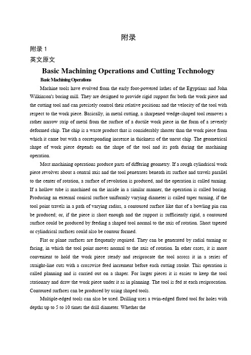
附录附录1英文原文Basic Machining Operations and Cutting TechnologyBasic Machining OperationsMachine tools have evolved from the early foot-powered lathes of the Egyptians and John Wilkinson's boring mill. They are designed to provide rigid support for both the work piece and the cutting tool and can precisely control their relative positions and the velocity of the tool with respect to the work piece. Basically, in metal cutting, a sharpened wedge-shaped tool removes a rather narrow strip of metal from the surface of a ductile work piece in the form of a severely deformed chip. The chip is a waste product that is considerably shorter than the work piece from which it came but with a corresponding increase in thickness of the uncut chip. The geometrical shape of work piece depends on the shape of the tool and its path during the machining operation.Most machining operations produce parts of differing geometry. If a rough cylindrical work piece revolves about a central axis and the tool penetrates beneath its surface and travels parallel to the center of rotation, a surface of revolution is produced, and the operation is called turning. If a hollow tube is machined on the inside in a similar manner, the operation is called boring. Producing an external conical surface uniformly varying diameter is called taper turning, if the tool point travels in a path of varying radius, a contoured surface like that of a bowling pin can be produced; or, if the piece is short enough and the support is sufficiently rigid, a contoured surface could be produced by feeding a shaped tool normal to the axis of rotation. Short tapered or cylindrical surfaces could also be contour formed.Flat or plane surfaces are frequently required. They can be generated by radial turning or facing, in which the tool point moves normal to the axis of rotation. In other cases, it is more convenient to hold the work piece steady and reciprocate the tool across it in a series of straight-line cuts with a crosswise feed increment before each cutting stroke. This operation is called planning and is carried out on a shaper. For larger pieces it is easier to keep the tool stationary and draw the work piece under it as in planning. The tool is fed at each reciprocation. Contoured surfaces can be produced by using shaped tools.Multiple-edged tools can also be used. Drilling uses a twin-edged fluted tool for holes with depths up to 5 to 10 times the drill diameter. Whether thedrill turns or the work piece rotates, relative motion between the cutting edge and the work piece is the important factor. In milling operations a rotary cutter with a number of cutting edges engages the work piece. Which moves slowly with respect to the cutter. Plane or contoured surfaces may be produced, depending on the geometry of the cutter and the type of feed. Horizontal or vertical axes of rotation may be used, and the feed of the work piece may be in any of the three coordinate directions.Basic Machine ToolsMachine tools are used to produce a part of a specified geometrical shape and precise I size by removing metal from a ductile material in the form of chips. The latter are a waste product and vary from long continuous ribbons of a ductile material such as steel, which are undesirable from a disposal point of view, to easily handled well-broken chips resulting from cast iron. Machine tools perform five basic metal-removal processes: I turning, planning, drilling, milling, and grinding. All other metal-removal processes are modifications of these five basic processes. For example, boring is internal turning; reaming, tapping, and counter boring modify drilled holes and are related to drilling; bobbing and gear cutting are fundamentally milling operations; hack sawing and broaching are a form of planning and honing; lapping, super finishing. Polishing and buffing are variants of grinding or abrasive removal operations. Therefore, there are only four types of basic machine tools, which use cutting tools of specific controllable geometry: 1. lathes, 2. planers, 3. drilling machines, and 4. milling machines. The grinding process forms chips, but the geometry of the abrasive grain is uncontrollable.The amount and rate of material removed by the various machining processes may be I large, as in heavy turning operations, or extremely small, as in lapping or super finishing operations where only the high spots of a surface are removed.A machine tool performs three major functions: 1. it rigidly supports the work piece or its holder and the cutting tool; 2. it provides relative motion between the work piece and the cutting tool; 3. it provides a range of feeds and speeds usually ranging from 4 to 32 choices in each case.Speed and Feeds in MachiningSpeeds, feeds, and depth of cut are the three major variables for economical machining. Other variables are the work and tool materials, coolant and geometry of the cutting tool. The rate of metal removal and power required for machining depend upon these variables.The depth of cut, feed, and cutting speed are machine settings that must be established in any metal-cutting operation. They all affect the forces, the power, and the rate of metal removal. They can be defined by comparing them to the needle and record of a phonograph. The cutting speed (V) is represented by the velocity of- the record surface relative to the needle in the tone arm at any instant. Feed is represented by the advance of the needle radially inward perrevolution, or is the difference in position between two adjacent grooves. The depth of cut is the penetration of the needle into the record or the depth of the grooves.Turning on Lathe CentersThe basic operations performed on an engine lathe are illustrated. Those operations performed on external surfaces with a single point cutting tool are called turning. Except for drilling, reaming, and lapping, the operations on internal surfaces are also performed by a single point cutting tool.All machining operations, including turning and boring, can be classified as roughing, finishing, or semi-finishing. The objective of a roughing operation is to remove the bulk of the material as rapidly and as efficiently as possible, while leaving a small amount of material on the work-piece for the finishing operation. Finishing operations are performed to obtain the final size, shape, and surface finish on the work piece. Sometimes a semi-finishing operation will precede the finishing operation to leave a small predetermined and uniform amount of stock on the work-piece to be removed by the finishing operation.Generally, longer work pieces are turned while supported on one or two lathe centers. Cone shaped holes, called center holes, which fit the lathe centers are drilled in the ends of the work piece-usually along the axis of the cylindrical part. The end of the work piece adjacent to the tail stock is always supported by a tail stock center, while the end near the head stock may be supported by a head stock center or held in a chuck. The head stock end of the work piece may be held in a four-jaw chuck, or in a type chuck. This method holds the work piece firmly and transfers the power to the work piece smoothly; the additional support to the work piece provided by the chuck lessens the tendency for chatter to occur when cutting. Precise results can be obtained with this method if care is taken to hold the work piece accurately in the chuck.Very precise results can be obtained by supporting the work piece between two centers. A lathe dog is clamped to the work piece; together they are driven by a driver plate mounted on the spindle nose. One end of the Work piece is mecained;then the work piece can be turned around in the lathe to machine the other end. The center holes in the work piece serve as precise locating surfaces as well as bearing surfaces to carry the weight of the work piece and to resist the cutting forces. After the work piece has been removed from the lathe for any reason, the center holes will accurately align the work piece back in the lathe or in another lathe, or in a cylindrical grinding machine. The work piece must never be held at the head stock end by both a chuck and a lathe center. While at first thought this seems like a quick method of aligning the work piece in the chuck, this must not be done because it is not possible to press evenly with the jaws against the work piece while it is also supported by the center. The alignment provided by the center will not be maintained and the pressure of the jaws may damage the center hole, the lathe center, andperhaps even the lathe spindle. Compensating or floating jaw chucks used almost exclusively on high production work provide an exception to the statements made above. These chucks are really work drivers and cannot be used for the same purpose as ordinary three or four-jaw chucks.While very large diameter work pieces are sometimes mounted on two centers, they are preferably held at the headstock end by faceplate jaws to obtain the smooth power transmission; moreover, large lathe dogs that are adequate to transmit the power not generally available, although they can be made as a special. Faceplate jaws are like chuck jaws except that they are mounted on a faceplate, which has less overhang from the spindle bearings than a large chuck would have.Introduction of MachiningMachining as a shape-producing method is the most universally used and the most important of all manufacturing processes. Machining is a shape-producing process in which a power-driven device causes material to be removed in chip form. Most machining is done with equipment that supports both the work piece and cutting tool although in some cases portable equipment is used with unsupported work piece.Low setup cost for small Quantities. Machining has two applications in manufacturing. For casting, forging, and press working, each specific shape to be produced, even one part, nearly always has a high tooling cost. The shapes that may he produced by welding depend to a large degree on the shapes of raw material that are available. By making use of generally high cost equipment but without special tooling, it is possible, by machining; to start with nearly any form of raw material, so tong as the exterior dimensions are great enough, and produce any desired shape from any material. Therefore .machining is usually the preferred method for producing one or a few parts, even when the design of the part would logically lead to casting, forging or press working if a high quantity were to be produced.Close accuracies, good finishes. The second application for machining is based on the high accuracies and surface finishes possible. Many of the parts machined in low quantities would be produced with lower but acceptable tolerances if produced in high quantities by some other process. On the other hand, many parts are given their general shapes by some high quantity deformation process and machined only on selected surfaces where high accuracies are needed. Internal threads, for example, are seldom produced by any means other than machining and small holes in press worked parts may be machined following the press working operations.Primary Cutting ParametersThe basic tool-work relationship in cutting is adequately described by means of four factors: tool geometry, cutting speed, feed, and depth of cut.The cutting tool must be made of an appropriate material; it must be strong, tough, hard, and wear resistant. The tool s geometry characterized by planes and angles, must be correct for each cutting operation. Cutting speed is the rate at which the work surface passes by the cutting edge. It may be expressed in feet per minute.For efficient machining the cutting speed must be of a magnitude appropriate to the particular work-tool combination. In general, the harder the work material, the slower the speed.Feed is the rate at which the cutting tool advances into the work piece. "Where the work piece or the tool rotates, feed is measured in inches per revolution. When the tool or the work reciprocates, feed is measured in inches per stroke, Generally, feed varies inversely with cutting speed for otherwise similar conditions.The depth of cut, measured inches is the distance the tool is set into the work. It is the width of the chip in turning or the thickness of the chip in a rectilinear cut. In roughing operations, the depth of cut can be larger than for finishing operations.The Effect of Changes in Cutting Parameters on Cutting TemperaturesIn metal cutting operations heat is generated in the primary and secondary deformation zones and these results in a complex temperature distribution throughout the tool, work piece and chip. A typical set of isotherms is shown in figure where it can be seen that, as could be expected, there is a very large temperature gradient throughout the width of the chip as the work piece material is sheared in primary deformation and there is a further large temperature in the chip adjacent to the face as the chip is sheared in secondary deformation. This leads to a maximum cutting temperature a short distance up the face from the cutting edge and a small distance into the chip.Since virtually all the work done in metal cutting is converted into heat, it could be expected that factors which increase the power consumed per unit volume of metal removed will increase the cutting temperature. Thus an increase in the rake angle, all other parameters remaining constant, will reduce the power per unit volume of metal removed and the cutting temperatures will reduce. When considering increase in unreformed chip thickness and cutting speed the situation is more complex. An increase in undeformed chip thickness tends to be a scale effect where the amounts of heat which pass to the work piece, the tool and chip remain in fixed proportions and the changes in cutting temperature tend to be small. Increase in cutting speed; however, reduce the amount of heat which passes into the work piece and this increase the temperature rise of the chip m primary deformation. Further, the secondary deformation zone tends to be smaller and this has the effect of increasing the temperatures in this zone. Other changes in cutting parameters have virtually no effect on the power consumed per unit volume of metal removed and consequently have virtually no effect on the cutting temperatures. Since ithas been shown that even small changes in cutting temperature have a significant effect on tool wear rate it is appropriate to indicate how cutting temperatures can be assessed from cutting data.The most direct and accurate method for measuring temperatures in high -speed-steel cutting tools is that of Wright &. Trent which also yields detailed information on temperature distributions in high-speed-steel cutting tools. The technique is based on the metallographic examination of sectioned high-speed-steel tools which relates microstructure changes to thermal history.Trent has described measurements of cutting temperatures and temperature distributions for high-speed-steel tools when machining a wide range of work piece materials. This technique has been further developed by using scanning electron microscopy to study fine-scale microstructure changes arising from over tempering of the tempered martens tic matrix of various high-speed-steels. This technique has also been used to study temperature distributions in both high-speed -steel single point turning tools and twist drills.Wears of Cutting ToolDiscounting brittle fracture and edge chipping, which have already been dealt with, tool wear is basically of three types. Flank wear, crater wear, and notch wear. Flank wear occurs on both the major and the minor cutting edges. On the major cutting edge, which is responsible for bulk metal removal, these results in increased cutting forces and higher temperatures which if left unchecked can lead to vibration of the tool and work piece and a condition where efficient cutting can no longer take place. On the minor cutting edge, which determines work piece size and surface finish, flank wear can result in an oversized product which has poor surface finish. Under most practical cutting conditions, the tool will fail due to major flank wear before the minor flank wear is sufficiently large to result in the manufacture of an unacceptable component.Because of the stress distribution on the tool face, the frictional stress in the region of sliding contact between the chip and the face is at a maximum at the start of the sliding contact region and is zero at the end. Thus abrasive wear takes place in this region with more wear taking place adjacent to the seizure region than adjacent to the point at which the chip loses contact with the face. This result in localized pitting of the tool face some distance up the face which is usually referred to as catering and which normally has a section in the form of a circular arc. In many respects and for practical cutting conditions, crater wear is a less severe form of wear than flank wear and consequently flank wear is a more common tool failure criterion. However, since various authors have shown that the temperature on the face increases more rapidly with increasing cutting speed than the temperature on the flank, and since the rate of wear of any type is significantly affected by changes in temperature, crater wear usually occurs at high cutting speeds.At the end of the major flank wear land where the tool is in contact with the uncut work piece surface it is common for the flank wear to be more pronounced than along the rest of the wear land. This is because of localised effects such as a hardened layer on the uncut surface caused by work hardening introduced by a previous cut, an oxide scale, and localised high temperatures resulting from the edge effect. This localised wear is usually referred to as notch wear and occasionally is very severe. Although the presence of the notch will not significantly affect the cutting properties of the tool, the notch is often relatively deep and if cutting were to continue there would be a good chance that the tool would fracture.If any form of progressive wear allowed to continue, dramatically and the tool would fail catastrophically, i. e. the tool would be no longer capable of cutting and, at best, the work piece would be scrapped whilst, at worst, damage could be caused to the machine tool. For carbide cutting tools and for all types of wear, the tool is said to have reached the end of its useful life long before the onset of catastrophic failure. For high-speed-steel cutting tools, however, where the wear tends to be non-uniform it has been found that the most meaningful and reproducible results can be obtained when the wear is allowed to continue to the onset of catastrophic failure even though, of course, in practice a cutting time far less than that to failure would be used. The onset of catastrophic failure is characterized by one of several phenomena, the most common being a sudden increase in cutting force, the presence of burnished rings on the work piece, and a significant increase in the noise level.Mechanism of Surface Finish ProductionThere are basically five mechanisms which contribute to the production of a surface which have been machined. These are:(l) The basic geometry of the cutting process. In, for example, single point turning the tool will advance a constant distance axially per revolution of the workpiecc and the resultant surface will have on it, when viewed perpendicularly to the direction of tool feed motion, a series of cusps which will have a basic form which replicates the shape of the tool in cut.(2) The efficiency of the cutting operation. It has already been mentioned that cutting with unstable built-up-edges will produce a surface which contains hard built-up-edge fragments which will result in a degradation of the surface finish. It can also be demonstrated that cutting under adverse conditions such as apply when using large feeds small rake angles and low cutting speeds, besides producing conditions which lead to unstable built-up-edge production, the cutting process itself can become unstable and instead of continuous shear occurring in the shear zone, tearing takes place, discontinuous chips of uneven thickness are produced, and the resultant surface is poor. This situation is particularly noticeable when machining very ductile materials such as copper and aluminum.(3) The stability of the machine tool. Under some combinations of cutting conditions; work piece size, method of clamping ,and cutting tool rigidity relative to the machine tool structure, instability can be set up in the tool which causes it to vibrate. Under some conditions this vibration will reach and maintain steady amplitude whilst under other conditions the vibration will built up and unless cutting is stopped considerable damage to both the cutting tool and work piece may occur. This phenomenon is known as chatter and in axial turning is characterized by long pitch helical bands on the work piece surface and short pitch undulations on the transient machined surface.(4)The effectiveness of removing swarf. In discontinuous chip production machining, such as milling or turning of brittle materials, it is expected that the chip (swarf) will leave the cutting zone either under gravity or with the assistance of a jet of cutting fluid and that they will not influence the cut surface in any way. However, when continuous chip production is evident, unless steps are taken to control the swarf it is likely that it will impinge on the cut surface and mark it. Inevitably, this marking besides looking.(5)The effective clearance angle on the cutting tool. For certain geometries of minor cutting edge relief and clearance angles it is possible to cut on the major cutting edge and burnish on the minor cutting edge. This can produce a good surface finish but, of course, it is strictly a combination of metal cutting and metal forming and is not to be recommended as a practical cutting method. However, due to cutting tool wear, these conditions occasionally arise and lead to a marked change in the surface characteristics.Limits and TolerancesMachine parts are manufactured so they are interchangeable. In other words, each part of a machine or mechanism is made to a certain size and shape so will fit into any other machine or mechanism of the same type. To make the part interchangeable, each individual part must be made to a size that will fit the mating part in the correct way. It is not only impossible, but also impractical to make many parts to an exact size. This is because machines are not perfect, and the tools become worn. A slight variation from the exact size is always allowed. The amount of this variation depends on the kind of part being manufactured. For examples part might be made 6 in. long with a variation allowed of 0.003 (three-thousandths) in. above and below this size. Therefore, the part could be 5.997 to 6.003 in. and still be the correct size. These are known as the limits. The difference between upper and lower limits is called the tolerance.A tolerance is the total permissible variation in the size of a part.The basic size is that size from which limits of size arc derived by the application of allowances and tolerances.Sometimes the limit is allowed in only one direction. This is known as unilateral tolerance.Unilateral tolerancing is a system of dimensioning where the tolerance (that is variation) is shown in only one direction from the nominal size. Unilateral tolerancing allow the changing of tolerance on a hole or shaft without seriously affecting the fit.When the tolerance is in both directions from the basic size it is known as a bilateral tolerance (plus and minus).Bilateral tolerancing is a system of dimensioning where the tolerance (that is variation) is split and is shown on either side of the nominal size. Limit dimensioning is a system of dimensioning where only the maximum and minimum dimensions arc shown. Thus, the tolerance is the difference between these two dimensions.Surface Finishing and Dimensional ControlProducts that have been completed to their proper shape and size frequently require some type of surface finishing to enable them to satisfactorily fulfill their function. In some cases, it is necessary to improve the physical properties of the surface material for resistance to penetration or abrasion. In many manufacturing processes, the product surface is left with dirt .chips, grease, or other harmful material upon it. Assemblies that are made of different materials, or from the same materials processed in different manners, may require some special surface treatment to provide uniformity of appearance.Surface finishing may sometimes become an intermediate step processing. For instance, cleaning and polishing are usually essential before any kind of plating process. Some of the cleaning procedures are also used for improving surface smoothness on mating parts and for removing burrs and sharp corners, which might be harmful in later use. Another important need for surface finishing is for corrosion protection in a variety of: environments. The type of protection procedure will depend largely upon the anticipated exposure, with due consideration to the material being protected and the economic factors involved.Satisfying the above objectives necessitates the use of main surface-finishing methods that involve chemical change of the surface mechanical work affecting surface properties, cleaning by a variety of methods, and the application of protective coatings, organic and metallic.In the early days of engineering, the mating of parts was achieved by machining one part as nearly as possible to the required size, machining the mating part nearly to size, and then completing its machining, continually offering the other part to it, until the desired relationship was obtained. If it was inconvenient to offer one part to the other part during machining, the final work was done at the bench by a fitter, who scraped the mating parts until the desired fit was obtained, the fitter therefore being a 'fitter' in the literal sense. J It is obvious that the two parts would have to remain together, and m the event of one having to be replaced, the fitting would have to be done all over again. In these days, we expect to be able to purchase a replacement fora broken part, and for it to function correctly without the need for scraping and other fitting operations.When one part can be used 'off the shelf' to replace another of the same dimension and material specification, the parts are said to be interchangeable. A system of interchangeability usually lowers the production costs as there is no need for an expensive, 'fiddling' operation, and it benefits the customer in the event of the need to replace worn parts.Automatic Fixture DesignTraditional synchronous grippers for assembly equipment move parts to the gripper centre-line, assuring that the parts will be in a known position after they arc picked from a conveyor or nest. However, in some applications, forcing the part to the centre-line may damage cither the part or equipment. When the part is delicate and a small collision can result in scrap, when its location is fixed by a machine spindle or mould, or when tolerances are tight, it is preferable to make a gripper comply with the position of the part, rather than the other way around. For these tasks, Zaytran Inc. Of Elyria, Ohio, has created the GPN series of non- synchronous, compliant grippers. Because the force and synchronizations systems of the grippers are independent, the synchronization system can be replaced by a precision slide system without affecting gripper force. Gripper sizes range from 51b gripping force and 0.2 in. stroke to 40Glb gripping force and 6in stroke. GrippersProduction is characterized by batch-size becoming smaller and smaller and greater variety of products. Assembly, being the last production step, is particularly vulnerable to changes in schedules, batch-sizes, and product design. This situation is forcing many companies to put more effort into extensive rationalization and automation of assembly that was previouslyextensive rationalization and automation of assembly that was previously the case. Although the development of flexible fixtures fell quickly behind the development of flexible handling systems such as industrial robots, there are, nonetheless promising attempts to increase the flexibility of fixtures. The fact that fixtures are the essential product - specific investment of a production system intensifies the economic necessity to make the fixture system more flexible.Fixtures can be divided according to their flexibility into special fixtures, group fixtures, modular fixtures and highly flexible fixtures. Flexible fixtures are characterized by their high adaptability to different work pieces, and by low change-over time and expenditure.There are several steps required to generate a fixture, in which a work piece is fixed for a production task. The first step is to define the necessary position of the work piece in the fixture, based on the unmachined or base pan, and the working features. Following this, a combination of stability planes must be selected. These stability planes constitute the fixture configuration in which the work piece is fixed in the defined position, all the forces or torques are compensated,。
机械加工表面质量
本文来至挖掘机维修:虽然机械零件加工表面的各种缺陷仅存在于表面层,但是,它却严重影响着零件的耐磨性、配合性质、抗腐蚀性和疲劳强度等使用性能,甚至还会影响到机械的使用寿命。
随着人类社会的发展及人们对产品质量要求的进一步提高,许多在高温、高压、重载等特殊环境下工作的重要零件,表面承受着巨大的应力和周围介质的腐蚀作用,零件表面的任何一处细微的缺陷都有可能导致零件的损坏。
产品工作性能如可靠性、耐久性的好坏,很大程度上取决于主要零件的表面质量。
研究机械加工表面质量及其影响因素,掌握其变化规律,对提高机械加工表面质量及产品使用性能具有重要的意义。
一、机械加工表面质量及其影响因素机械加工表面质量,主要表现在以下两个方面:一是零件加工表面存在着表面粗糙度、波度等表面几何形状误差;二是由于加工过程中的产生表面塑性变形,引起的冷作硬化现象;因切削热导致的表面金相组织变化以及残余应力等物理机械性能的变化。
(一)表面粗糙度及其影响因素表面粗糙度是指零件表面存在着的微观不平度。
表面粗糙度可分为横向粗糙度和纵向粗糙度,把垂直于切削速度方向的粗糙度称为横向粗糙度;把沿切削速度方向的粗糙度称为纵向粗糙度。
一般来说,横向粗糙度较大,它主要由刀具几何因素和切削因素两方面共同作用形成,纵向粗糙度则主要由切削因素形成。
机床—刀具—工件系统的振动也常是引起粗糙度的重要因素。
1、刀具几何形状:在理想切削状态下,刀具相对于工件作进给运动时,在已加工表面上遗留下来的切削层残留面积,形成理论粗糙度,其最大高度Rmax可由刀具形状、进给量f按几何关系求得。
在刀尖圆弧半径为零时,可由下式求得:式中f----工件每转的进给量;---车刀的主偏角---车刀的副偏角实际车刀刀尖总有圆角半径r,此时Rmax可由下式求得:在切削过程中,工件受到刀具的刃口圆角及后面的挤压、摩擦产生塑性变形,导致理论残留面积被挤歪、沟纹加深,因而增大了表面粗糙度。
2、切削因素:通常在切削速度较低的情况下切削塑性材料时,易于产生刀瘤与鳞刺,刀瘤与鳞刺会使表面粗糙度严重恶化。
机械加工专业毕业设计外文翻译
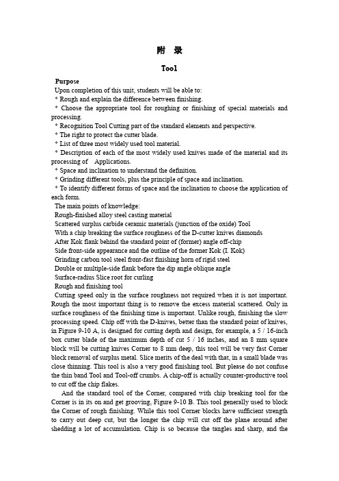
附录ToolPurposeUpon completion of this unit, students will be able to:* Rough and explain the difference between finishing.* Choose the appropriate tool for roughing or finishing of special materials and processing.* Recognition Tool Cutting part of the standard elements and perspective.* The right to protect the cutter blade.* List of three most widely used tool material.* Description of each of the most widely used knives made of the material and its processing of Applications.* Space and inclination to understand the definition.* Grinding different tools, plus the principle of space and inclination.* To identify different forms of space and the inclination to choose the application of each form.The main points of knowledge:Rough-finished alloy steel casting materialScattered surplus carbide ceramic materials (junction of the oxide) ToolWith a chip breaking the surface roughness of the D-cutter knives diamondsAfter Kok flank behind the standard point of (former) angle off-chipSide front-side appearance and the outline of the former Kok (I. Kok)Grinding carbon tool steel front-fast finishing horn of rigid steelDouble or multiple-side flank before the dip angle oblique angleSurface-radius Slice root for curlingRough and finishing toolCutting speed only in the surface roughness not required when it is not important. Rough the most important thing is to remove the excess material scattered. Only in surface roughness of the finishing time is important. Unlike rough, finishing the slow processing speed. Chip off with the D-knives, better than the standard point of knives, in Figure 9-10 A, is designed for cutting depth and design, for example, a 5 / 16-inch box cutter blade of the maximum depth of cut 5 / 16 inches, and an 8 mm square block will be cutting knives Corner to 8 mm deep, this tool will be very fast Corner block removal of surplus metal. Slice merits of the deal with that, in a small blade was close thinning. This tool is also a very good finishing tool. But please do not confuse the thin band Tool and Tool-off crumbs. A chip-off is actually counter-productive tool to cut off the chip flakes.And the standard tool of the Corner, compared with chip breaking tool for the Corner is in its on and get grooving, Figure 9-10 B. This tool generally used to block the Corner of rough finishing. While this tool Corner blocks have sufficient strength to carry out deep cut, but the longer the chip will cut off the plane around after shedding a lot of accumulation. Chip is so because the tangles and sharp, and theoperator is a dangerous, so this is a chip from the need to address the problem. Double, or triple the speed of the feed will help to resolve, but this will require greater horsepower and still easily chip very long. Because of the slow processing, however, this action will be a good tool but also because of the small root radius of the processing will be a smooth surface. Especially when processing grey cast iron especially.Cutting Tools appearanceAppearance, sometimes called the contour of the floor plan is where you see the vision or the top down or look at the surface. Figure 9-11 illustrate some of the most common form, those who could be on the cutting tools and grinding out successfully be used. National Standards in its thread-cutting tool on a tiny plane can be as GB thread, the Anglo-American unity and international standards screw threads. A special tool to outline the thread of the plane is to be ground into the correct size.Tools Corner fixedCorner to a number of knives around the 15 degree angle while the other knives and cutting of the straight. When the mill in Figure 9-12 A and 9-12 B, for example by the space and the inclination, these must factor into consideration in the review. Figure 9-12 B Tool Corner block the angle is zero, compared with 9-12 A map is a heavier cutting tools, and the 9-12 A map will take more heat. The same amount of space in front of the two cases are the same.Tool Corner block component and the angleFigure 9-13 Tool Corner block an integral part of the name, and plans 9-14 point of the name, is the machinery industry standards.Grinding Wheel Tool Corner BlockWhen the cutter is fixed in the middle of Dao, Tool Corner block can not be the grinding. Can not do so for the reasons: because of the large number of Dao and extra weight, making Corner together with the grinding is a clumsy and inefficient way. Too much pressure could be added to round on the sand. This can cause the wheel Benglie wheel or because of overheating and the rift on the Corner Tool damage. There are grinding to the possibility of Dao.GrindingA craftsman in his toolbox, should always be a small pocket lining grinding tool. Alumina lining a grinding tool as carbon tool steel and high speed steel tool tool. The silicon carbide lining grinding tool grinding carbide cutting tools. Cutting Tools should always maintain smooth and sharp edge, so that the life expectancy of long knives and processing the surface smooth.Cutting tool materialsCarbon tool steel cutter Corner block usually contains 1.3 percent to 0.9 percent of carbon. These make use of the cutting tool in their tempering temperature higher than about 400 degrees Fahrenheit (205 degrees Celsius) to 500 degrees Fahrenheit (260 degrees Celsius) remained hardness, depending on the content of carbon. These temperature higher than that of carbon tool steel cutter will be changed soft, and it will be the cutting edge. Damaged. Grinding blades or cutting speed faster when using carbon tool steel cutter will be made of the blue, this will be in the imagination. Toolwill be re-hardening and tempering again. So in a modern processing almost no carbon as a tool steel blade.Low-alloy steel cutting tool in the carbon steel tools added tungsten, cobalt, vanadium alloying elements such as the consequences. These elements and the hardness of high-carbon carbide. Increased tool wear resistance. Alloy tool steel that is to say there will be no hard and fast with hot red when the knife's edge can still continue to use it. Low-alloy steel cutting tool is relatively small for a modern processing.High-speed steel with tungsten of 14 percent to 22 percent, or Containing 1.5% to 6% of the W-Mo (molybdenum which accounted for 6 percent to 91 percent). From high-speed steel tool made of a rigid heat, some high-speed steel also contains cobalt, which is formed of rigid factor. Cobalt containing high-speed steel tool can maintain hardness, more than 1,000 degrees Fahrenheit (or 540 degrees Celsius) blade will become soft and easily damaged. After cooling, the tool will harden. When grinding, you must be careful because of overheating and cold at first, so that profile Benglie Zhucheng a variety of metal alloy materials have a special name called Carbide, such as containing tungsten carbide cobalt chrome. In little or iron carbide. However, its high-speed steel cutting speed than the maximum cutting speed is higher 25 percent to 80 percent. Carbide Tool General for cutting force and the intermittent cutting processing, such as processing Chilled Iron.The past, Carbide Tool is mainly used for processing iron, but now carburizing tool for processing all the metal.Carbide Tool into the body than to the high-speed steel tool or casting - lighter alloy cutting tools, because tend to be used as a tool carbide cutting tools. Pure tungsten, carbon carburizing agent or as a dipping formation of the tungsten carbide, suitable for the cast iron, aluminum, non-iron alloy, plastic material and fiber of the machining. Add tantalum, titanium, molybdenum led to the carbon steel The hardness of higher tool, this tool suitable for processing all types of steel. In manufacturing, or tungsten steel alloy containing two or more of a bonding agent and the mixture is hard carbon steel tool, is now generally containing cobalt, cobalt was inquiry into powder and thoroughly mixed, under pressure Formation of Carbide.These cutting tools in the temperature is higher than 1,660 degrees F (870 degrees C) can also be efficiently used. Carbide Tool hardware than high-speed steel tool, used as a tool for better wear resistance. Carbide Tool in a high-speed Gangdao nearly three times the maximum cutting speed of the cutting rate cutting.Made from diamonds to the cutting tool on the surface finish and dimensional accuracy of the high demand and carbide cutting tools can be competitive, but these tools processing the material was more difficult, and difficult to control. Metal, hard rubber and plastic substances can be effective tool together with diamonds and annoyance to the final processing.Ceramic tool (or mixed oxide) is mixed oxide. With 0-30 grade alumina mixture to do, for example, contains about 89 percent to 90 percent of alumina and 10 percent to 11 percent of titanium dioxide. Other ceramic tool is used with the tiny amount of the second oxides Mixed together the cause of pure alumina.Ceramic tools in more than 2,000 degrees F (1095 degrees C) temperature of the work is to maintain strength and hardness. Cutting rates than high-carbon steel knives to 50 percent or even hundreds of percentage. In addition to diamonds and titanium carbide, ceramic tool in the industry is now all the materials of the most hard cutting tool, especially at high temperatures.Tao structure easily broken in a specific situation, broken only carbon intensity of the half to two-thirds. Therefore, in cut, according to the proportion of cutting and milling would normally not be recommended. Ceramics cutting machine breakdown of failure is not usually wear failure, as compared with other materials, their lack of ductility and lower tensile strength.In short, the most widely used by the cutting tool material is cut high-speed steel, low alloy materials and carbide.Gap and dipSpace and inclination of the principle is the most easily to the truck bed lathe tool bladed knives to illustrate. Shape, size of the gap, and dip the type and size will change because of machining. Similarly a grinding tool Corner block is just like brushing your teeth.Gap tool to stop the edge of friction with the workpiece. If there is no gap in Figure 9-15A in the small blades, knives and the side will wear will not be cutting. If there are gaps in Figure 9-15 B, will be a cutting tool. This basic fact apply to any type of tool.Clearance was cutting the size depends on material and the cutting of the material deformation. For example, aluminum is soft and easy to slightly deformed or uplift, when the cutter Corner into space within the perspective and the perspective of the space under, the equivalent in steel mill and will very quickly broken. Table 9-1 (No. 340) that different materials grinding space and perspective.The correct amount of space will be properly protected edge. Too much space will cause the blade vibration (fibrillation), and may edge of total collapse. Tool Corner for the slab block must have a backlash, behind (in front) gap, knife and cut-corner. The main cutting edge is almost as all the cutting work at the cutting edge of the cutting tool on the edge, on the left or right-lateral knives, or cutting tool in the end, cut off on a cutter.Backlash angle for example, the role of a lathe tool Corner to the left block when it mobile. If there is no backlash Kok, Fig 9-16 A, with the only tool will be part of friction rather than cutting. If a suitable backlash Kok, Fig 9-16 B, will be cutting edge and will be well supported. If I have too many gaps, Fig 9-16 C, the edge will not support leading tool vibration (fibrillation) and may be completely broken.Tool gap to the front or rear of the role when it fixed to zero, as shown in Figure 9-17. If not in front of the Gap. Figure 9-17 A, the tool will not only friction and cutting. If a suitable space in front, Fig 9-17 B, but also a good tool will be cutting edge will be well supported. If a big gap in front of Ms, Fig 9-17 C, the tool will lack support, will have a vibrate, and cutting edge may be pressure ulcer.Figure 9-18 illustrate the gap in front of a lathe tool, when it with a 15 degree angle when fixed. The same amount of space on the front fixed to zero, and around thecutter, but the tool is the relatively thin. So the heat away from the blade less. Typically, front-side or front-not too big in Figure 9-19. It is usually from zero degrees to 20 degrees change, an average of about 15 degrees. There are clear advantages, according to the following: good cutting angle so that the cutting edge of the work was well, but relatively thin chips. Cutting Tools is the weakest part. By the former angle, the blade In the form of points around the workpiece. Cutting Edge shock will cause the entire tool vibration. When cutting the work nearly completed, the final section of metal was to ring, packing iron sheet or tangles in the form of the metal ball away gradually replaced by direct removal. Pressure tends to stay away from the workpiece cutting tool rather than narrow the gap between its parts. 9-19 A in the plan was an example of the use of a 30-degree lateral Cutting Angle tool processing thin slice example. A mathematical proof of the plan 9-19 B in the right-angle triangle trip is to expand the use of a map 9-19 A right triangle in the same way, that is, in the direction of upward mobility to feed a 0.010 inch. Right triangle adjacent to the edge (b) and feed 0.010 feet equivalent.The following formula using triangulation to explain:Kok cosine A = right-angle-B / C XiebianOr cosine of 30 degrees = b / c0.886 = b/0.010b = 0.866 * 0.010b = 0.00866 (bladed too thin)When the mobile tool, the purpose of front-to be processed to eliminate from the surface of the cut-cutting tools. This angle is usually from 8 degrees to 15 degrees, but in exceptional circumstances it as much as 20 degrees to 30 degrees. If there is no gap in Figure 9-20 A, cutting tools will be tied up, sharp beep, and the rivets may be the first to die away. The appropriate space, in Figure 9-20 B, cutting tool will be cutting well.A manufacturing plant or cut off the fast-cutter blade with three space, in a root-surface or surface and the other in bilateral level, in Figure 9-21. If a tool Corner block from the date of the face, It can have up to five space, in Figure 9-22. Grooving tool sometimes known as area reduction tool used to cut a groove in the shallow end of the thread.Inclination is the top tool inclination or, in the Tool Corner block on the surface. Changes depending on the angle of the cutting material. Improvement of the cutting angle, the blade shape, and guidelines from the chip from the edge of the direction. Chip dip under the direction named. For example, if a chip from the edge cutter outflow, it is called anterior horn. If the chip to the back of the outflow, that is, to the Dao, which is known as the horn. Some mechanical error and the staff horn as a front-or knife corner.Single tool like Tool Corner block may be the only edge of the blade side oblique angle, or in the back, only to end on the edge of the horn, or they may have roots in the face or front surface of the main Cutting edge of the blade and cutting edge of the horn and a roll angle of the portfolio. In the latter case, cut off most of the surface with a cutter and a chip to the point of view in the tool horn and roll angle in bothdirections has been moved out.Two different roll angle in Figure 9-23 A and 9-23 B was an example. Angle depends on the size and type of material was processed.9-24 A map in Figure 9-24 B and gives examples of zero to a fixed cutter after the two different angle. In Figure 9-25 B and 9-25 A Tool to the regular 15-degree angle. Figure 9-26 tool to display a 15 degree angle fixed, but in this case a tool to roll angle after angle and the combination of form close to the workpiece. Double or multiple chips to lead the inclination angle of a mobile or two away from the edge of the back and side to stay away from the cutter.Comparison of various horn, shown in Figure 9-27, Corner of the horn of a negative point of view, and zero is the point of view. These dip in the Corner cutter on the manifestation of a decision in the hands of the processing needs of the pieces. After Kok was the size of the type of materials processing, and knives in Dao fixed on the way.The type of lateral oblique angleFigure 9-28 examples of tools Corner blocks and four different types of lateral oblique angle of the cross-sectional. Figure 9-28 A, is zero lateral oblique angle, like some of the brass materials, some bronze and some brittle plastic material is particularly necessary. Standard side oblique angle, in Figure 9-28 B, is the most common one of the bevel side. In the ductile material on the deep cut, easy to chip in the tool around the accumulation of many, and this will cause danger to the operator. The chip will become a deal with the problem. Such a tool to cut off the grey cast iron is the most appropriate.Chip laps volumes, Figure 9-28 C, is one of the best types of inclination, especially in the ductile material on the special deep cutting. Chip small crimp in close formation against the Dao of bladed knives against the will of the rupture. The chip rolled up to maintain a narrow trough of the chip will guarantee that the width of closely Lane V ol. The chip is very easy to handle. V olume circle with a chip is not a cut-chip.Chip cut off, in Figure 9-28 D, leading to chip in the corner was cut off, and then to small chips fell after the chip. The need to cut off a chip provides up to 25 percent of the force. This inclination of the stickiness of the steel is good.Gap KokWhen cutting any material time, the gap should always be the smallest size, but the gap should never angle than the required minimum angle small space. The gap is too small knives Kok will lead to friction with the workpiece. Choice of space at the corner to observe the following points:1. When processing hardness, stickiness of the material, the use of high-speed steel tool cutting angle should be in the space of 6 to 8 degrees, and the use of carbon tool steel cutter at the corner of the gap in size should be 5 degrees to 7 degrees.2. When the processing of carbon steel, low carbon steel, cast iron when the gap angle should be the size of high-speed steel tool 8 degrees to 12 degrees, and carbon tool steel cutter 5 degrees to 10 degrees.3. Scalability when processing materials such as copper, brass, bronze, aluminum,iron, etc. Zhanxing materials, space Kok should be the size of high-speed steel tool 12 degrees to 16 degrees, carbon steel knives 8 degrees to 14 , Mainly because of the plastic deformation of these metals. This means that, when the cutter and around them, the soft metal to some minor deformation or protruding, and this tool will be friction. At this time, we must have a tool on the additional space.刀具目的在完成这一个单元之后,学生将会能够:* 解释粗加工和精加工之间的差别。
机械加工切削加工中英文对照外文翻译文献
中英文资料翻译英文部分The new concept of cutting processingThe nowadays cutting tool company cannot only be again the manufacture and the sales cutting tool, in order to succeed, they must be consistent with the globalization manufacture tendency maintenance, through enhances the efficiency, cooperates with the customer reduces the cost. Approaches the instantaneous global competition after this after NAFTA, the WTO time, the world company is making quickly to the same feeling, is lighter, a cheaper response. In other words, they make the product and the components contain can in high speed under revolve, as a result of the cost pressure, best, is lighter moreover must make cheaply. Obtains these goals a best way is through develops and applies the new material, but these is new and the improvement material usually all with difficulty processes. In in this kind of commercial power and the technical difficulty combination is especially prominent in the automobile and the aviation industry, and has become has the experience the cutting tool company to research and develop the department the most important driving influence.For example, takes the modular cast iron to say that, it has become the engine part and other automobiles, the agriculture the material which see day by day with the equipment and in the machine tool industry components. This kind of alloy provides the low production cost and the good machine capability combination. They are cheaper than the steel products, but has a higher intensity and toughness compared to the cast iron. But at the same time the modular cast iron is extremely wear-resisting, has fast breaks by rubbing the cutting tool material the tendency. In this wear resistant very great degree bead luminous body content influence. Some known modular cast iron bead luminous body content higher, its resistance to wear better, moreover its machinability is worse. Moreover, the modular cast iron porosity causes off and on to cut, this even more reduces the life.May estimate that, the high degree of hardness and the high wear-resisting cutting material quality must consider the modular cast iron the high resistance to wear. And the material quality contains extremely hard TiC in fact (carbonized titanium) or TiCN (carbon titanium nitrides) thick coating when cutting speed each minute 300 meters processes the modular cast iron to prove usually is effective. But along with cutting speed increase, scrap/The cutting tool junctionplane temperature also is increasing. When has such situation, the TiC coating favors in has the chemical reaction with the iron and softens, more pressures function in anti- crescent moon hollow attrition coating. Under these conditions, hoped has one chemical stability better coating, like Al2O3 (although under low speed was inferior to TiC hard or is wear-resisting).The chemical stability becomes an important performance performance dividing line compared to the resistance to wear the factor, the speed and the temperature is decided in is processed the modular cast iron the crystal grain structure and the performance. But usually thick coating of TiCN and TiC or only ductile iron oxides in the soil coating is applied to, because the today majority of this kinds are processed the material the cutting speed in each minute 150 to 335 meters between. Is higher than each minute 300 meter applications regarding the speed, the people to this kind of material are satisfied.In order to cause this scope performance to be most superior, the mountain high researched and developed and has promoted in view of modular cast iron processing material quality TX150. This kind of material quality has hard also the anti- distortion substrate, is very ideal regarding the processing modular cast iron. Its coating the oxide compound coating which hollowly wears by thick very wear-resisting carbon titanium nitrides and a thin anti- crescent moon, the top is thin layer TiN. This kind of coating which needs the center warm chemistry gas phase deposition using the state of the art production resistance to wear and the anti- crescent moon hollow attrition which the CVD coating complete degree of hardness moreover the tough smoothness increases (MTCVD) the craft. Substrate/The coating combination performance gives the very high anti- plastic deformation and the cutting edge micro collapses the ability, causes it to become under the normal speed to process the modular cast iron the ideal material quality.The coating ceramics also display can effectively process the modular cast iron. In the past, the aluminum oxide ceramics application which not the coating tough good such as nitriding silicon and the silicon carbide textile fiber strengthened the work piece material chemistry paralysis limit. Today but could resist the scrap distortion process through the use to have the high thermal coating cutting tool life already remarkably to increase. But certain early this domains work piece processing use aluminum oxides spread the layer crystals to have to strengthen the ceramics, today most research concentrate in the TiN coating nitriding silicon. This kind of coating can remarkably open up the tough good ceramics the application scope.When machining, the work piece has processed the surface is depends upon the cutting tool and the work piece makes the relative motion to obtain.According to the surface method of formation, the machining may divide into the knife point path law, the formed cutting tool law, the generating process three kinds.The knife point path law is depends upon the knife point to be opposite in the work piecesurface path, obtains the superficial geometry shape which the work piece requests, like the turning outer annulus, the shaping plane, the grinding outer annulus, with the profile turning forming surface and so on, the knife point path are decided the cutting tool and the work piece relative motion which provides in the engine bed;The formed cutting tool law abbreviation forming, is with the formed cutting tool which matches with the work piece final superficial outline, or the formed grinding wheel and so on processes the formed surface, like formed turning, formed milling and form grinding and so on, because forms the cutting tool the manufacture quite to be difficult, therefore only uses in processing the short formed surface generally;The generating process name rolls cuts method, is when the processing the cutting tool and the work piece do unfold the movement relatively, the cutting tool and the work piece centrode make the pure trundle mutually, between both maintains the definite transmission ratio relations, obtains the processing surface is the knife edge in this kind of movement envelope, in the gear processing rolls the tooth, the gear shaping, the shaving, the top horizontal jade piece tooth and rubs the tooth and so on to be the generating process processing.Some machining has at the same time the knife point path law and the formed cutting tool method characteristic, like thread turning.The machining quality mainly is refers to the work piece the processing precision and the surface quality (including surface roughness, residual stress and superficial hardening).Along with the technical progress, the machining quality enhances unceasingly.The 18th century later periods, the machining precision counts by the millimeter; At the beginning of 20th century, machining precision Gao Yida 0.01 millimeter; To the 50's, the machining precision has reached a micron level; The 70's, the machining precision enhances to 0.1 micron.The influence machining quality primary factor has aspects and so on engine bed, cutting tool, jig, work piece semifinished materials, technique and processing environment.Must improve the machining quality, must take the suitable measure to the above various aspects, like reduces the engine bed work error, selects the cutting tool correctly, improves the semifinished materials quality, the reasonable arrangement craft, the improvement environmental condition and so on.Enhances the cutting specifications to enhance the material excision rate, is enhances the machining efficiency the essential way.The commonly used highly effective machining method has the high-speed cutting, the force cutting, the plasma arc heating cuts and vibrates the cutting and so on.The grinding speed is called the high-speed grinding in 45 meters/second above es the high-speed cutting (or grinding) both may enhance the efficiency, and mayreduce the surface roughness.The high-speed cutting (or grinding) requests the engine bed to have the high speed, the high rigidity, the high efficiency and the vibration-proof good craft system; Requests the cutting tool to have the reasonable geometry parameter and the convenience tight way, but also must consider the safe reliable chip breaking method.The force cutting refers to the roughing feed or cuts the deep machining greatly, uses in the turning and the grinding generally.The force turning main characteristic is the lathe tool besides the main cutting edge, but also some is parallel in the work piece has processed superficial the vice-cutting edge simultaneously to participate in the cutting, therefore may enhance to feed quantity compared to the general turning several times of even several pares with the high-speed cutting, the force cutting cutting temperature is low, the cutting tool life is long, the cutting efficiency is high; The shortcoming is processes the surface to be rough.When force cutting, the radial direction cutting force death of a parent is not suitable for to process the tall and slender work piece very much.The vibration cutting is along the cutting tool direction of feed, the attachment low frequency or the high frequency vibration machining, may enhance the cutting efficiency.The low frequency vibration cutting has the very good chip breaking effect, but does not use the chip breaking equipment, makes the knife edge intensity to increase, time the cutting total power dissipation compared to has the chip breaking installment ordinary cutting to reduce about 40%.The high frequency vibration cutting also called the ultrasonic wave vibration cutting, is helpful in reduces between the cutting tool and the work piece friction, reduces the cutting temperature, reduces the cutting tool the coherence attrition, thus the enhancement cutting efficiency and the processing surface quality, the cutting tool life may enhance 40% approximately.To lumber, plastic, rubber, glass, marble, granite and so on nonmetallic material machining, although is similar with the metal material cutting, but uses the cutting tool, the equipment and the cutting specifications and so on has the characteristic respectively.The lumber product machining mainly carries in each kind of joiner's bench, its method mainly has: The saw cuts, digs cuts, the turning, the milling, drills truncates with the polishing and so on.The plastic rigidity is worse than the metal, the easy bending strain, the thermoplastic thermal conductivity to be in particular bad, easy to elevate temperature the conditioning.When cutting plastic, suitably with the high-speed steel or the hard alloy tools, selects the small to feed quantity and the high cutting speed, and uses compressed air cooling.If the cutting tool is sharp, the angle is appropriate, may produce the belt-shaped scrap, easy to carry off the quantity of heat.Glass (including semiconducting material and so on germanium, silicon) but degree of hardness high brittleness is big.To methods and so on glass machining commonly used cutting, drill hole, attrition and polishing.To thickness in three millimeters following glass plates, the simple cutting method is with the diamond or other hard materials, in glass surface manual scoring, the use scratch place stress concentration, then uses the hand to break off.To the marble, the granite and the concrete and so on the hard material processing, mainly uses methods and so on cutting, turning, drill hole, shaping, attrition and polishing.When cutting the available circular saw blade adds the grinding compound and the water; The outer annulus and the end surface may use the negative rake the hard alloy lathe tool, by 10~30 meter/minute cutting speed turning; Drills a hole the available hard alloy drill bit; The big stone material plane available hard alloy planing tool or rolls cuts planing tool shaping; The precise smooth surface, available three mutually for the datum to the method which grinds, or the grinding and the polishing method obtains.Cutting tool in hot strong alloy applicationThe aviation processing also changes rapidly. For example, nickel base heat-resisting alloy like several years ago the most people had not heard Rene88 now occupies to the aircraft engine manufacture uses the total metal quantity 10~25%. Has very good showing and the commercial reason regarding this. For example, these heat strong alloy will be able to increase the engine endurance moreover to permit the small engine work on the big airplane, that will enhance the combustion efficiency and reduces the operation cost. These tough good materials also present the expense on the cutting tool. Their thermal stability causes on the knife point the temperature to be higher, thus reduced the cutting tool life. Similarly, in these alloy carbide pellet remarkably increased the friction, thus reduces the cutting tool life.As a result of changes in these conditions, can be very pleased to have processed many titanium alloys and nickel-based alloy materials C-2 hard metal alloys, in the application to today's cutting edge of blade to the crushing and cutting depth of the trench lines badly worn. But using the latest high-temperature processing of small particles hard metal alloys to be effective, cutlery life improved, but more importantly to enhance the reliability of applications in high-temperature alloys. Small particles hard metal than traditional hard metal materials higher compression strength and hardness, only a small increase in the resilience of the cost. And resulted in high temperature alloy processing than traditional hard metal resistance common failure mode more effective.PVD (physical gas phase deposition) coating also by certificate effective processing heat-resisting alloy. TiN (titanium nitrides) the PVD coating was uses and still was most early most receives welcome. Recently, TiAlN (nitrogen calorization titanium) and TiCN (carbontitanium nitrides) the coating also could very good use. In the past the TiAlN coating application scope and TiN compared the limit to be more. But after the cutting speed enhances them is a very good choice, enhances the productivity in these applications to reach 40%. On the other hand, is decided under the low cutting speed in coating superficial operating mode TiAlN can cause to accumulate the filings lump afterwards, micro collapses with the trench attrition.Recently, used in the heat-resisting alloy application material quality already developing, these coating but became by several combinations. The massive laboratories and the scene test has already proven this kind of combination and other any kind of sole coating compares in time the very wide scope application is very effective. Therefore aims at the heat-resisting alloy application the PVD compound coating possibly to become the focal point which the hard alloy new material quality research and development continues. With the MTCVD coating, the coating ceramics gather in the same place, they hopefully become a more effective processing to research and develop newly are more difficult to process the work piece material the main impact strength.Dry processingIncluding the refrigerant question is technical and the commercial expansion industrial production tendency another domain which the cutting tool makes. North America and the European strict refrigerant management request and the biggest three automobile manufacturer forces them the core supplier to obtain the ISO14000 authentication (the ISO9000 environment management edition), this causes the refrigerant processing cost rise. To the car company and their core supplier said obviously one of responses which welcome is in the specific processing application avoids completely the refrigerant the use. This kind did the processing the new world to propose a series of challenges for the cutting tool supplier.Recently, already appeared some to concern this topic to promulgate the speed, to enter for, the coating chemical composition and other parameters very substantial comprehensive nature very strong useful technical papers. Wants to concentrate the elaboration in here me "does the processing viewpoint" in the operation and commercial meaning automobile manufacturer new.The metal working jobholders can the very good understanding related refrigerant use question, but majority cannot understand concerns except the technical challenge (for example row of filings) beside does the processing question in the cutting tool - work piece contact face between. Usually may observe to the refrigerant disperser scrap which flows out, but the pressure surpasses 3,000 pounds/An inch 2 high speed refrigerant also can help to break the filings, specially soft also the continual scrap can cause in the cutting tool - work piece contact face trouble.Uses does the cutting craft the components result is the engine bed uses the wet typeprocessing components to be hotter than. Whether before you do allow them to survey in the open-air natural cooling? If processes newly the hot components put frequently to the turnover box, elevates the environment temperature, whether components full cooling and just right enough permission precision examination? Also has the handling side several dozens on hundred components to be able to operate the worker to increase the extra burden.With many cutting tools/The work piece technical question same place, these latent questions need to state whether dryly adds the ability line. Luckily, has very many ways to elaborate these questions. For example, the compressed air was proven row of filings becomes the question in very many applications the situation to have the successful echo.Another plan is called MQL (minimum lubrication) a technology, it replaces the traditional refrigerant by the application the quite few oil mists constitution. This is a recognition compromise plan, this kind of minimum technology can large scale reduce the refrigerant the headache matter, moreover the smooth finish which processes in many applications very is also good. This domain still had very many research to do, moreover the cutting tool company positively participated in such research was absolutely essential. If they will not do fall behind the competitor, will be at the disadvantageous position.In the factory the special details design other perhaps better plan according to the world in. The manufacturing industry jobholders possibly still could ask why they do have to use recent development the technology to replace the refrigerant method diligently which the tradition already an experience number generation of person improved enhances, because implemented especially does the experiment and the defeat which the processing or the subarid processing produced possibly causes the higher short-term cutting tool cost. The concise answer is when the bit probably accounts for the model processing components cost 3%, the refrigerant cost (from purchases to maintenance, storage, processing) can account for the components cost 15%.Perhaps does the dry processing is not all suits to each application, but above discusses likely other processing questions are same, needs from a wider operation, the environment and the commercial angle appraises. Will be able to help the cutting tool company which the customer will do this to have the competitive advantage, but these will not be able to provide unceasingly is in the passive position.Cutting tool and nanotechnologyCan fiercely change the cutting tool industry the enchanting new domain is the miniature manufacture, or the processing small granule forms the product which needs. Must refer to is its here does not have about the cutting tool miniature manufacture first matter; Second must say the matter is it is not remote.Why the miniature manufacture and are the cutting tool related. Because most main is theparticle size smaller, the hard alloy toughness of material better also is more wear-resisting. (Some experts define with the nanometer level pellet for are smaller than 0.2 mu m, but other people persisted a nanometer pellet had to be smaller than the hard alloy tools prototype which 0.1 mu m) made already to complete and the test,It is said that wear resistant theatrically increase. The question is the nanometer level hard alloy pellet cannot depend on the smashing big material formation, they are certain through the smaller material constitution, but processes the molecular level granule is not easy and the economical matter.中文部分切削加工新概念现今的刀具公司再也不能只是制造和销售刀具,为了成功,他们必须与全球化制造趋势保持一致,通过提高效率、同客户合作来降低成本。
机械加工表面质量
迫振动的显著差别。
3)自激振动能否产生以及振幅的大小,决定于每一振动周期 内系统所获得的能量与所消耗的能量的对比情况。 4)自激振动的形成和持续,是由于过程本身产生的激振和反 馈作用。
3.消除自激振动的途径
(1)合理选择与切削过程有关的参数 1)合理选择切削用量 车削中通常切削速度v在50~60m/min左右稳定性最低,最 易产生自激振动,所以可选择高速或低速切削以避免自激振动。
影响冷作硬化的主要因素有: 1) 刀具的影响
2) 切削用量的影响
切削速度增大,硬化层深度和硬度都有所减小。 进给量f增大时,切削力增大,塑性变形程度也增大,因此 硬化现象增大;但在进给量f较小时,由于刀具的刃口圆角在
加工表面单位长度上的挤压次数增多,因此硬化现象也会增
大。 3) 被加工材料的影响 硬度愈小,塑性愈大的材料切削后的
3)实际生产中还往往用油石使新刃磨的刃口稍稍钝化,也 根有效。关于刀尖圆弧半径,它本来 就相加工表面粗糙度有 关,对加工中的振动而言,一般不要取得太大。车削时装刀位 置过低或镗孔时装刀位置过高,都易于产生自激振动。 4)使用“油”性非常高的润滑剂也是加工中经常使用的一 种 防振办法。
(2) 提高工艺系统本身的抗振性 1)提高机床的抗振性
第5章 机械加工表面质量 Surface quality Quality control 表面完整性—— Surface integrity
机械加工表面质量包含: 1.几何参数方面的质量:机械加工表面本身的精度 尺寸精度 形状精度
位置精度
2.物理机械方面的质量:冷硬程度和深度 残余应力的性质和大小 本章重点讲解:物理机械方面的质量和表面粗糙度
①减小进给量 f; H ctgK f ctgK ' ; H 8f
机械加工——机械类外文翻译、中英文翻译

TOOL WEAR MECHANISMS ON THE FLANK SURFACE OF CUTTINGINSERTSFOR HIGH SPEED WET MACHINING5.1 IntroductionAlmost every type of machining such as turning, milling, drilling, grinding..., uses a cutting fluid to assist in the cost effective production of pa rts as set up standard required by the producer [1]. Using coolant with some cutting tools material causes severe failure due to the lack of their resistance to thermal shock (like AL2O3 ceramics), used to turn steel. Other cutting tools materials like cubic boron nitride (CBN) can be used without coolant, due to the type of their function. The aim of using CBN is to raise the temperature of the workpice to high so it locally softens and can be easily machined.The reasons behind using cutting fluids can be summarized as follows.® Extending the cutting tool life achieved by reducing heat generated and as a result less wear rate is achieved. It will also eliminate the heat from theshear zone and the formed chips.® Cooling the work piece of high quality materia l under operation plays an important role since thermal distortion of the surface and subsurfacedamage is a result of excessive heat that must be eliminated or largelyreduced to produce a high quality product.Reducing cutting forces by its lubricating e ffect at the contact interface region and washing and cleaning the cutting region during machining from small chips. The two main reasons for using cutting fluids are cooling and lubrication.Cutting Fluid as a Coolant:The fluid characteristics and condition of use determine the coolant action of the cutting fluid, which improves the heat transfer at the shear zone between the cutting edge, work piece, and cutting fluid. The properties of the coolant in this case must include a high heat capacity to carry away heat and good thermal conductivity to absorb the heat from the cutting region. The water-based coolant emulsion with its excellent high heat capacity is able to reduce tool wear [44]. Cutting Fluid as a Lubricant:The purpose is to reduce friction bet ween the cutting edge, rake face and the work piece material or reducing the cutting forces (tangential component). As the friction drops the heat generated isdropped. As a result, the cutting tool wear rate is reduced and the surface finish is improved.Cutting Fluid PropertiesFree of perceivable odorPreserve clarity throughout lifeKind and unirritated to skin and eyes.Corrosion protection to the machine parts and work piece.Cost effective in terms off tool life, safety, dilution ratio, and fluid lif e.[1]5.1.1 Cutting Fluid TypesThere are two major categories of cutting fluidsNeat Cutting OilsNeat cutting oils are poor in their coolant characteristics but have an excellent lubricity. They are applied by flooding the work area by a pump and re-circulated through a filter, tank and nozzles. This type is not diluted by water, and may contain lubricity and extreme-pressure additives to enhance their cutting performance properties. The usage of this type has been declining for their poor cooling ability, causing fire risk, proven to cause health and safety risk to the operator [1].® Water Based or Water Soluble Cutting FluidsThis group is subdivided into three categories:1.Emulsion ` mineral soluble' white-milky color as a result of emulsion of oil inwater. Contain from 40%-80% mineral oil and an emulsifying agent beside corrosion inhibitors, beside biocide to inhibit the bacteria growth.2.Micro emulsion `semi-synthetic' invented in 1980's, has less oil concentrationand/or higher emulsifier ratio 10%-40% oil. Due to the high levels ofemulsifier the oil droplet size in the fluid are smaller which make the fluid more translucent and easy to see the work piece during operation. Otherimportant benefit is in its ability to emulsify any leakage of oil from themachine parts in the cutting fluid, a corrosion inhibitors, and bacteria control.3.Mineral oil free `synthetic' is a mix of chemicals, water, bacteria control,corrosion inhibitors, and dyes. Does not contain any mineral oils, andprovides good visibility.23 to the work piece. bare in mind that the lack of mineral oil in this type of cuttingfluid needs to take more attention to machine parts lubrication since it should not leave an oily film on the machine parts, and might cause seals degradation due the lack of protection.5.1.2 Cutting Fluid SelectionMany factors influence the selection of cutting fluid; mainly work piece material, type of machining operation, machine tool parts, paints, and seals. Table 5-1 prepared at the machine tool industry res earch association [2] provides suggestions on the type of fluid to be used.5.1.3 Coolant ManagementTo achieve a high level of cutting fluids performance and costeffectiveness, a coolant recycling system should be installed in the factory. This system will reduce the amount of new purchased coolant concentrate and coolant disposable, which will reduce manufacturing cost. It either done by the company itself or be rented out, depends on the budget and management policy of the company [1].Table 5-1 Guide to the selection of cutting fluids for general workshop applications.Machining operation Workpiece materialFree machining and low - carbon Medium- Carbon steels High Carbon and alloy steels Stainlessand heattreated GrindingClear type soluble oil, semi synthetic or chemical Turning General purpose, soluble oil, semi synthetic or synthetic fluid Extreme-pressuresoluble oil,semi-synthetic orsyntheticfluid Milling General purpose, soluble oil, semi synthetic or synthetic Extreme- pressure soluble oil, semi- synthetic or synthetic Extreme-pressuresoluble oil,semi-synthetic orsyntheticfluid(neat cutting oilsmay beDrillingExtreme- pressure soluble oil, semi- synthetic or GearShapping Extreme-pressure soluble oil, Neat-cutting oils preferable HobbingExtreme-pressure soluble oil, semi-synthetic or synthetic fluid (neat cutting oils may be Neat-cutti ng oils BratchingExtreme-pressure soluble oil, semi-synthetic or synthetic fluid (neat Tapping Extreme-pressure soluble oil, semi-synthetic or Neat-cuttingpreferableNote: some entreis deliberately extend over two or more columns, indicating awide range of possible applications. Other entries are confined to aspecific class of work material.Adopt ed f rom Edw ard and Wri ght [2]5.2 Wear Mechanisms Under Wet High Speed M achiningIt is a common belief that coolant usage in metal cutting reduces cuttingtemperature and extends tools life. However, this researchshowed that this is not necessarily true to be generalized overcutting inserts materials. Similar research was ca rried out ondifferent cutting inserts materials and cutting conditionssupporting our results. Gu et al [36] have recorded adifference in tool wear mechanisms between dry and wetcutting of C5 milling inserts. Tonshoff et al [44] alsoexhibited different wear mechanisms on AL 2O 3/TiC inserts inmachining ASTM 5115, when using coolants emulsionscompared to dry cutting. In addition, Avila and Abrao [20]experienced difference in wear mechanisms activated at theflank side, when using different coolants in t estingAL 2O 3lTiC tools in machining AISI4340 steel. The wearmechanisms and the behavior of the cutting inserts studied inthis research under wet high speed-machining (WHSM)condition is not fully understood. Therefore, it was theattempt of this research to focus on the contributions incoating development and coating techniques of newlydeveloped materials in order to upgrade their performance attough machining conditions. This valuable research providesinsight into production timesavings and increase inprofitability. Cost reductions are essential in the competitiveglobal economy; thus protecting local markets and consistingin the search of new ones.5.3 Experimental Observations on Wear Mechanisms of Un-CoatedCemented Carbide Cutting Inserts in High Speed WetMachiningIn this section, the observed wear mechanisms are presented of uncoated cemented carbide tool (KC313) in machining ASTM 4140 steel under wet condition. The overall performance of cemented carbide under using emulsion coolant has been improved in terms of extending tool life and reducing machining cost. Different types of wear mechanisms were activated at flank side of cutting inserts as a result of using coolant emulsion during machining processes. This was due to the effect of coolant in reducing the average temperature of the cutting tool edge and shear zone during machining. As a result abrasive wear was reduced leading longer tool life. The materials of cutting tools behave differently to coolant because of their varied resistance to thermal shock. The following observations recorded the behavior of cemented carbide during high speed machining under wet cutting.Figure5-1 shows the flank side of cutting inserts used at a cutting speed of 180m/min. The SEM images were recorded after 7 minutes of machining. It shows micro-abrasion wear, which identified by the narrow grooves along the flank side in the direction of metal flow, supported with similar observations documented by Barnes and Pashby [41] in testing through-coolant-drilling inserts of aluminum/SiC metal matrix composite. Since the cutting edge is the weakest part of the cutting insert geometry, edge fracture started first due to the early non-smooth engagement between the tool and the work piece material. Also, this is due to stress concentrations that might lead to a cohesive failure on the transient filleted flank cutting wedge region [51, 52]. The same image of micro-adhesion wear can be seen at the side and tool indicated by the half cone27 shape on the side of cutting tool. To investigate further, a zoom in view was taken atthe flank side with a magnification of 1000 times and presented in Figure 5-2A. It shows clear micro-abrasion wear aligned in the direction of metal flow, where the cobalt binder was worn first in a hi gher wear rate than WC grains which protruded as big spherical droplets. Figure 5-2B provides a zoom-in view that was taken at another location for the same flank side. Thermal pitting revealed by black spots in different depths and micro-cracks, propagated in multi directions as a result of using coolant. Therefore, theii~ial pitting, micro-adhesion and low levels of micro-abrasion activated under wet cutting; while high levels of micro-abrasion wear is activated under dry cutting (as presented in the prev ious Chapter).Figure 5-3A was taken for a cutting insert machined at 150mlmin. It shows a typical micro-adhesion wear, where quantities of chip metal were adhered at the flank side temporarily. Kopac [53] exhibited similar finding when testing HSS-TiN drill inserts in drilling SAE1045 steel. This adhered metal would later be plucked away taking grains of WC and binder from cutting inserts material and the process continues. In order to explore other types of wear that might exist, a zoom-in view with magnification of 750 times was taken as shown in Figure5-3B. Figure 5-3B show two forms of wears; firstly, micro-thermal cracks indicated by perpendicular cracks located at the right side of the picture, and supported with similar findings of Deamley and Trent [27]. Secondly, micro-abrasion wear at the left side of the image where the WC grains are to be plucked away after the cobalt binder was severely destroyed by micro-abrasion. Cobalt binders are small grains and WC is the big size grains. The severe distort ion of the binder along with the WC grains might be due to the activation of micro-adhesion and micro-abrasionFigure 5-1 SEM image of (KC313) showing micro abrasion and micro-adhesion (wet).SEM micrographs of (KC313) at 180m/min showing micro-abrasion where cobalt binder was worn first leaving protruded WC spherical droplets (wet).(a)SEM micrographs of (KC313) at 180m/min showing thermal pitting (wet).Figure 5-2 Magnified views of (KC313) under wet cutting: (a) SEM micrographs of (KC313) at 180mlmin showing micro-abrasion where cobalt binderwas worn first leaving protruded WC spherical droplets (wet ), (b) SEMmicrographs of (KC313) at 180.m/min showing thermal pitting (wet ).SEM image showing micro-adhesion wear mechanism under 150m/min (wet).(a)SEM image showing micro-thermal cracks, and micro-abrasion.Figure 5-3 Magnified views of (KC313) at 150m/min (wet): (a) SEM image showing micro-adhesion wear mechanism under 150m/min (wet), (b) SEM image showing micro-fatigue cracks, and micro-abrasion (wet).Wear at the time of cutting conditions of speed and coolant introduction. Therefore, micro-fatigue, micro-abrasion, and micro-adhesion wear mechanisms are activated under wet condition, while high levels of micro-abrasion were observed under dry one.Next, Figure 5-4A was taken at the next lower speed (120m/min). It shows build up edge (BUE) that has sustained its existence throughout the life of the cutting tool, similar to Huang [13], Gu et al [36] and Venkatsh et al [55]. This BUE has protected the tool edge and extended its life. Under dry cutting BUE has appeared at lower speeds (90 and 60 m/min), but when introducing coolant BUE started to develop at higher speeds, This is due to the drop in shear zone temperature that affected the chip metal fl ow over the cutting tool edge, by reducing the ductility to a level higher than the one existing at dry condition cutting. As a result, chip metal starts accumulating easier at the interface between metal chip flow, cutting tool edge and crater surface to form a BUE. In addition to BUE formation, micro-abrasion wear was activated at this speed indicated by narrow grooves.To explore the possibility of other wear mechanisms a zoom-in view with a magnification of 3500 times was taken and shown in Figure 5-4B. Micro- fatigue is evident by propagated cracks in the image similar to Deamley and Trent [27] finding. Furthermore, Figure 5-4B shows indications of micro-abrasion wear, revealed by the abrasion of cobalt binder and the remains of big protruded WC grains. However, the micro-abrasion appeared at this speed of 120m/min is less severe than the same type of micro-wear observed at 150m/min speed, supported with Barnes [41] similar findings. Therefore, micro-abrasion, BUE and micro-fatigue were activated under wet condition while, adhesion, high levels micro-abrasion, and no BUE were under dry cutting.SEM i m a g e o f(KC313) showing build up e d g e under 120m/min (wet).(a)SEM i m a g e o f(KC3 13) showing micro-fatigue, and micro-abrasion (wet). Figure 5-4 SEM images of (KC313) at 120m/min (wet), (a) SEM image of (KC313). showing build up edge, (b) SEM image of(K C313) showing micro-fatigue and micro-abrasion33 Figure 5-5 is for a cutting tool machined at 90m/min, that presents a goodcapture of one stage of tool life after the BUE has been plucked away. The bottom part of the flank side shows massive metal adhesion from the work piece material. The upper part of the figure at the edge shows edge fracture. To stand over the reason of edge fracture, the zoom-in view with magnification of 2000 times is presented in Figure 5-6A. The micro-fatigue crack image can be seen as well as micro-attrition revealed by numerous holes, and supported with Lim et al [31] observations on HSS-TiN inserts. As a result of BUE fracture from the cutting tool edge, small quantities from the cutting tool material is plucked away leaving behind numerous holes. Figure 5-6B is another zoom-in view of the upper part of flank side with a magnification of 1000 times and shows micro-abrasion wear indicated by the narrow grooves. Furthermore, the exact type of micro-wear mechanism appeared at the flank side under 60 m/min. Therefore, in comparison with dry cutting at the cutting speed of 90 m/min and 60 m/min, less micro-abrasion, bigger BUE formation, and higher micro-attrition rate were activated.Figure 5-5 SEM image showing tool edge after buildup edge was plucked away.SEM image showing micro-fatigue crack, and micro-attrition.(a)SEM image showing micro-abrasion.Figure 5-6 SEM images of (KC313) at 90m/min:(a) SEM image showing micro-fatigue crack, and micro-attrition, (b) SEM image showingmicro-abrasion.5.4 Experimental Observations on Wear Mechanisms of Coated CementedCarbide with TiN-TiCN-TiN Coating in High Speed WetMachiningInvestigating the wear mechanisms of sandwich coating under wet cutting is presented in this section starting from early stages of wear. Figure 5-7 shows early tool wear starting at the cutting edge when cutting at 410m/min. Edge fracture can be seen, it has started at cutting edge due to non-smooth contact between tool, work piece, micro-abrasion and stress concentrations. To investigate further the other possible reasons behind edge fracture that leads to coating spalling, a zoom-in view with magnification of 2000 ti mes was taken and presented at Figure 5-8A. Coating fracture can be seen where fragments of TiN (upper coating) had been plucked away by metal chips. This took place as result of micro-abrasion that led to coating spalling. On the other hand, the edge is t he weakest part of the cutting insert geometry and works as a stress concentrator might lead to a cohesive failure on the transient filleted flank cutting wedge region [51, 52].Both abrasion wear and stress concentration factor leave a non-uniform edge configuration at the micro scale after machining starts. Later small metal fragments started to adhere at the developed gaps to be later plucked away by the continuous chip movement as shown in Figure 5-8A. Another view of edge fracture was taken of the same cutting tool with a magnification of 2000 times as shown in Figure 5-8B. It presents fracture and crack at the honed tool edge. A schematic figure indicated by Figure 5-9, presented the progressive coated cutting inserts failure starting at the insert edge. It was also noticed during the inserts test that failure takes place first at the inserts edge then progressed toward the flank side. Consequently, a study on optimizing the cutting edgeFigure 5-7 SEM image of (KC732) at 410m/min showing edge fractur e and micro-abrasion (wet).SEM image showing edge fracture.(a)SEM image showing fracture and crack at the honed insert edge.Figure 5-8 SEM of (KC732) at 410m/min and early wear stage (wet): (a) SEM image showing edge fracture, (b) SEM image showing fr acture and crack atthe honed insert edge.radius to improve coating adhesion, and its wear resistance, might be also a topic for future work.Figure 5-1.0A was taken after tool failure at a speed of 410m/min. It shows completely exposed substrate and severe sliding wear at the flank side. The coating exists at the crater surface and faces less wear than the flank side. Therefore it works as an upper protector for the cutting edge and most of the wear will take place at the flank side as sliding wear. Figu re 5-10B is a zoom-in view with magnification of 3500 times, and shows coating remaining at the flank side. Nonetheless, micro-abrasion and a slight tensile fracture in the direction of metalchip flow. Ezugwa et al [28] and Kato [32] have exhibited simila r finding. However, the tensile fracture in this case is less in severity than what had been observed at dry cutting. This is due to the contribution of coolant in dropping the cutting temperature, which has reduced the plastic deformation at high temperature as a result. Hence, in comparison with the dry cutting at the same speed, tensile fracture was available with less severity and micro-abrasion/sliding. However, in dry cutting high levels of micro-abrasion, high levels of tensile fracture and sliding wear occurred.Figure 5-11 was taken at early stages of wear at a speed of 360m/min. It shows sliding wear, coating spalling and a crack starting to develop between TiN and TiCN coating at honed tool edge. Figure5-12A shows nice presentation of what had been described earlier regarding the development of small fragments on the tool edge. The adhered metal fragments work along with micro-abrasion wear to cause coating spalling.SEM image showing sliding wear.(a)SEM image showing micro-abrasion and tensile fracture.Figure 5-10 SEM images of (KC732) at 410m/min after failure (wet): (a) SEM image showing sliding wear, (b) SEM image showing micro-abrasionand tensile fracture.Figure 5-11 SEM image at early stage of wear of 360m/min (wet) showing coating and spalling developing crack between TiN and TiCN layers.The size of the metal chip adhered at the edge is almost 15g. Since it is unstable it will be later plucked away taking some fragments of coatings with it and the process continues. Another zoom in view with a magnification of 5000 times for the same insert is shown in Figure 5-12B indicating a newly developed crack between the coating layers.Figure 5-13A is taken of the same insert after failure when machining at 360m/min and wet condition. Coating spalling, and sliding wear can be seen and indicated by narrow grooves. In addition, initial development of notch wear can be seen at the maximum depth of cut.Further investigation is carried out by taking a zoom in view with a magnification of 2000 times as shown in Figure 5-13B. A clear micro-abrasion wear and micro-fatigue cracks were developed as shown, which extended deeply through out the entire three coating layers deep until the substrate. Therefore, in comparison with dry cutting, micro-fatigue crack, less tensile fracture, less micro-abrasion wear were activated at wet cutting. While micro- fatigue crack, high levels of micro-abrasion, and high levels of tensile fracture are distinguish the type of wear under dry condition at the same cutting spee d.Next, Figure 5-14A is taken for cutting tools machined at 310m/min. The results are similar to the previous inserts machined at 360m/min, where adhesion of metal fragments occurred at the tool edge, sliding wear and coating spalling. In addition, the black spot appeared at the top of the figure on the crater surface is a void resulting from imperfections in the coating process. At this condition, the crater surface will be worn faster than the flank surface.SEM image showing adhered metal fragments at tool edge.(a)SEM image showing developed crack between coating layers.Figure 5-12 SEM image of (KC732) at early wear 360m/min (wet): (a) SEM image showing adhered metal fragments at tool edge, (b) SEM image showingdeveloped crack between coating layers.(a)SEM image showing coating spalling and sliding wear after tool failure(b)SEM image showing micro-abrasion, and micro-fatigue cracks developedbetween coating layersFigure 5-13 SEM image of KC732 after failure machined at 360m/min(b)(wet): (a) SEM image showing coating spalling and sliding wear after toolfailure, (b) SEM image showing micro-abrasion, and micro-fatiguecracks developed between coating layers.翻译:在高速潮湿机械加工条件下后刀面表层磨损机理5.1 介绍几乎每类型用机器制造譬如转动, 碾碎, 钻井, 研..., 使用切口流体协助零件的有效的生产当设定标准由生产商[ 1 ] 需要。
机械加工表面质量

机械加工表面质量机器零件的破坏,一般都是从表面层开头的。
一、加工表面质量的概念加工表面质量包含以下两个方面的内容:1.加工表面的几何形貌(1)表面粗糙度(2)表面波纹度(3)表面纹理方向(4)表面缺陷2.表面层材料的物理力学性能(1)表面层的冷作硬化(2)表面层残余应力(3)表面层金相组织变化二、机械加工表面质量对机器使用性能的影响1.表面质量对耐磨性的影响(1)表面粗糙度对耐磨性的影响(2)表面冷作硬化对耐磨性的影响(3)表面纹理对耐磨性的影响2. 表面质量对零件疲惫强度的影响3. 表面质量对抗腐蚀性能的影响4.表面质量对零件协作性质的影响三、加工表面的表面粗糙度切削加工的表面粗糙度值主要取决于切削残留面积的高度。
加工塑性材料时,切削速度v对加工表面粗糙度加工相同材料的工件,晶粒越粗大,切削加工后的表面粗糙度值越大。
适当增大刀具的前角,可以降低被切削材料的塑性变形;降低刀具前刀面和后刀面的表面粗糙度可以抑制积屑瘤的生成;增大刀具后角,可以削减刀具和工件的摩擦;合理选择冷却润滑液,可以削减材料的变形和摩擦,降低切削区的温度;实行上述各项措施均有利于减小加工表面的粗糙度。
四、加工表面的物理力学性能(一)表面层材料的冷作硬化1.冷作硬化的评定参数2.影响冷作硬化的因素(1)刀具的影响(2)切削用量的影响(3)加工材料的影响(二)表面层材料金相组织变化假如磨削区温度超过马氏体转变温度而未超过相变临界温度(碳钢的相变温度为723℃),这时工件表层金属的金相组织,由原来的马氏体转变为硬度较低的回火组织(索氏体或托氏体),这种烧伤称为回火烧伤;假如磨削区温度超过了相变温度,在切削液急冷作用下,表层金属将发生二次淬火,硬度高于原来的回火马氏体,里层金属则由于冷却速度慢,消失了硬度比原先的回火马氏体低的回火组织,这种烧伤称为淬火烧伤;若工件表层温度超过相变温度,而磨削区又没有冷却液进入,表层金属便产生退火组织,硬度急剧下降,称之为退火烧伤。
01-教材参考内容——机械加工后的表面质量

~~~~~~~~~~~~~~~~~~~~~~~~~" Simpo PDF Merge and S 8plit 机Un 械reg 加iste 工re 表d V 面ers 质ion 量- ~~~~~~~~~~~~~~~~~~~~~~~~~~~~~~~~~~~~~~~~~" 本 章 提 要 机械加工的表面质量与机械产品的使用性能>使用寿命和可靠性密切相关o 任何经过机械加工的零件表面◆都不是完全理想的表面◆总是存在一定程度的微观不 平>表面缺陷>冷作硬化>残余应力及金相组织的变化等现象o 虽然这些变化只发生在很薄的零件表面层◆但实践证明◆机械零件的腐蚀>磨损和疲劳断裂等失效事故常 常起源于表面◆而且表面缺陷总是造成事故的根源之一o 这说明零件的机械加工表 面质量对零件和产品的质量有着直接的影响o 本章主要讲述了机械加工表面质量和表面完整性的含义◆介绍了表面质量和表面完整性对耐磨性>疲劳性>腐蚀性等使用性能的影响◆分析了零件表面和表面层在 加工中的变化和发生变化的机理◆以及机械加工中各种工艺因素对零件表面和表面层的影响规律◆对生产现场中发生的残余应力>磨削烧伤>磨削裂纹等表面质量和表 面完整性问题从理论上作出了解释;本章最后简要介绍了一类提高零件表面质量和表面完整性的主要加工技术◆即零件表面光整加工技术的内涵及几种典型的光整加工工艺o8﹒1 机械加工后的表面质量8﹒1﹒1 表面质量的含义零件的表面按照它的形成方法可分为毛坯表面和机械加工表面。
一般机械加工后的零件总是存在与基 体材料不同的一个很薄的表面层,机械加工表面质量是指零件加工后表面的几何形状特征和表面层的物理 机械性能。
机械加工表面质量的含义有两方面的内容:(1)表面的几何形状特征 表面粗糙度:指表面微观几何形状误差,其波长与波高的比值在L 1/H 1 <40 的范围内,如图8﹒1 所示。
机械加工表面加工质量

机械加工表面加工质量1. 引言在机械加工过程中,表面加工质量是一个非常重要的指标。
表面加工质量的好坏直接影响到产品的性能和外观。
因此,了解和掌握机械加工表面加工质量的相关知识是非常重要的。
本文将从表面加工质量的定义、影响因素以及常见的提高方法等方面进行探讨,并介绍一些常用的测试方法和评价标准。
2. 表面加工质量定义表面加工质量是指零件经过机械加工后表面的光洁度、平整度、粗糙度以及其他相关指标的好坏程度。
在实际应用中,表面加工质量常常用Ra 值、Rz值以及其他一些参数来表示。
•Ra值:表示零件表面的平均粗糙度,单位为微米。
Ra值越小,表面越光滑。
•Rz值:表示零件表面上峰值与谷值的高度差,单位为微米。
Rz值越小,表面越平整。
3. 表面加工质量的影响因素表面加工质量受到如下因素的影响:3.1 材料性质原材料的性质直接影响着表面加工的质量。
不同材料具有不同的硬度、韧性以及切削性,这些都会对加工后的表面质量产生重要的影响。
3.2 加工参数加工参数包括切削速度、进给速度、切削深度等。
这些参数的选择直接影响着加工后表面的质量。
不恰当的加工参数会导致材料的“剥离”或者“焊着”,从而影响表面质量。
3.3 加工工艺不同的加工工艺对表面加工质量的影响也有所不同。
例如,不同的切削方式(如铣削、车削等)以及不同的刀具形状都会对表面质量产生重要的影响。
3.4 刀具磨损刀具的磨损直接影响着切削质量和表面加工质量。
磨损严重的刀具容易导致表面加工的毛刺、阴刃等问题,从而影响表面质量。
4. 提高表面加工质量的方法为了提高表面加工质量,我们可以采取以下几种方法:4.1 优化加工工艺合理选择加工工艺,根据具体情况进行优化。
比如,对于需要高精度表面加工的零件,可以选择小切削深度、较低的进给速度和切削速度等。
4.2 提高刀具质量选择优质的刀具,减少刀具磨损对表面加工质量的影响。
定期进行刀具的保养和更换,保证刀具的尖锐度和稳定性。
4.3 加工前处理加工前的处理对于提高表面加工质量也非常重要。
机械加工外文文献翻译
外文原文MACHINABILITYThe machinability of a material usually defined in terms of four factors:1、Surface finish and integrity of the machined part;2、Tool life obtained;3、Force and power requirements;4、Chip control.Thus, good machinability good surface finish and integrity, long tool life, and low force And power requirements. As for chip control, long and thin (stringy) cured chips, if not broken up, can severely interfere with the cutting operation by becoming entangled in the cutting zone.Because of the complex nature of cutting operations, it is difficult to establish relationships that quantitatively define the machinability of a material. In manufacturing plants, tool life and surface roughness are generally considered to be the most important factors in machinability. Although not used much any more, approximate machinability ratings are available in the example below.1、Machinability Of SteelsBecause steels are among the most important engineering materials (as noted in Chapter 5), their machinability has been studied extensively. The machinability of steels has been mainly improved by adding lead and sulfur to obtain so-calledfree-machining steels.Resulfurized and Rephosphorized steels. Sulfur in steels forms manganese sulfide inclusions (second-phase particles), which act as stress raisers in the primary shear zone. As a result, the chips produced break up easily and are small; this improves machinability. The size, shape, distribution, and concentration of these inclusions significantly influence machinability. Elements such as tellurium and selenium, which are both chemically similar to sulfur, act as inclusion modifiers in resulfurized steels.Phosphorus in steels has two major effects. It strengthens the ferrite, causing increased hardness. Harder steels result in better chip formation and surface finish.Note that soft steels can be difficult to machine, with built-up edge formation and poor surface finish. The second effect is that increased hardness causes the formation of short chips instead of continuous stringy ones, thereby improving machinability.Leaded Steels. A high percentage of lead in steels solidifies at the tip of manganese sulfide inclusions. In non-resulfurized grades of steel, lead takes the form of dispersed fine particles. Lead is insoluble in iron, copper, and aluminum and their alloys. Because of its low shear strength, therefore, lead acts as a solid lubricant (Section 32.11) and is smeared over the tool-chip interface during cutting. This behavior has been verified by the presence of high concentrations of lead on thetool-side face of chips when machining leaded steels.When the temperature is sufficiently high-for instance, at high cutting speeds and feeds (Section 20.6)—the lead melts directly in front of the tool, acting as a liquid lubricant. In addition to this effect, lead lowers the shear stress in the primary shear zone, reducing cutting forces and power consumption. Lead can be used in every grade of steel, such as 10xx, 11xx, 12xx, 41xx, etc. Leaded steels are identified by the letter L between the second and third numerals (for example, 10L45). (Note that in stainless steels, similar use of the letter L means “low carbon,” a condition that improves their corrosion resistance.)However, because lead is a well-known toxin and a pollutant, there are serious environmental concerns about its use in steels (estimated at 4500 tons of lead consumption every year in the production of steels). Consequently, there is a continuing trend toward eliminating the use of lead in steels (lead-free steels). Bismuth and tin are now being investigated as possible substitutes for lead in steels.Calcium-Deoxidized Steels. An important development is calcium-deoxidized steels, in which oxide flakes of calcium silicates (CaSo) are formed. These flakes, in turn, reduce the strength of the secondary shear zone, decreasing tool-chip interface and wear. Temperature is correspondingly reduced. Consequently, these steels produce less crater wear, especially at high cutting speeds.Stainless Steels. Austenitic (300 series) steels are generally difficult to machine. Chatter can be s problem, necessitating machine tools with high stiffness. However, ferritic stainless steels (also 300 series) have good machinability. Martensitic (400 series) steels are abrasive, tend to form a built-up edge, and require tool materials with high hot hardness and crater-wear resistance. Precipitation-hardening stainless steelsare strong and abrasive, requiring hard and abrasion-resistant tool materials.The Effects of Other Elements in Steels on Machinability. The presence of aluminum and silicon in steels is always harmful because these elements combine with oxygen to form aluminum oxide and silicates, which are hard and abrasive. These compounds increase tool wear and reduce machinability. It is essential to produce and use clean steels.Carbon and manganese have various effects on the machinability of steels, depending on their composition. Plain low-carbon steels (less than 0.15% C) can produce poor surface finish by forming a built-up edge. Cast steels are more abrasive, although their machinability is similar to that of wrought steels. Tool and die steels are very difficult to machine and usually require annealing prior to machining. Machinability of most steels is improved by cold working, which hardens the material and reduces the tendency for built-up edge formation.Other alloying elements, such as nickel, chromium, molybdenum, and vanadium, which improve the properties of steels, generally reduce machinability. The effect of boron is negligible. Gaseous elements such as hydrogen and nitrogen can have particularly detrimental effects on the properties of steel. Oxygen has been shown to have a strong effect on the aspect ratio of the manganese sulfide inclusions; the higher the oxygen content, the lower the aspect ratio and the higher the machinability.In selecting various elements to improve machinability, we should consider the possible detrimental effects of these elements on the properties and strength of the machined part in service. At elevated temperatures, for example, lead causes embrittlement of steels (liquid-metal embrittlement, hot shortness; see Section 1.4.3), although at room temperature it has no effect on mechanical properties.Sulfur can severely reduce the hot workability of steels, because of the formation of iron sulfide, unless sufficient manganese is present to prevent such formation. At room temperature, the mechanical properties of resulfurized steels depend on the orientation of the deformed manganese sulfide inclusions (anisotropy). Rephosphorized steels are significantly less ductile, and are produced solely to improve machinability.2、Machinability of Various Other MetalsAluminum is generally very easy to machine, although the softer grades tend to form a built-up edge, resulting in poor surface finish. High cutting speeds, high rakeangles, and high relief angles are recommended. Wrought aluminum alloys with high silicon content and cast aluminum alloys may be abrasive; they require harder tool materials. Dimensional tolerance control may be a problem in machining aluminum, since it has a high thermal coefficient of expansion and a relatively low elastic modulus.Beryllium is similar to cast irons. Because it is more abrasive and toxic, though, it requires machining in a controlled environment.Cast gray irons are generally machinable but are. Free carbides in castings reduce their machinability and cause tool chipping or fracture, necessitating tools with high toughness. Nodular and malleable irons are machinable with hard tool materials.Cobalt-based alloys are abrasive and highly work-hardening. They require sharp, abrasion-resistant tool materials and low feeds and speeds.Wrought copper can be difficult to machine because of built-up edge formation, although cast copper alloys are easy to machine. Brasses are easy to machine, especially with the addition pf lead (leaded free-machining brass). Bronzes are more difficult to machine than brass.Magnesium is very easy to machine, with good surface finish and prolonged tool life. However care should be exercised because of its high rate of oxidation and the danger of fire (the element is pyrophoric).Molybdenum is ductile and work-hardening, so it can produce poor surface finish. Sharp tools are necessary.Nickel-based alloys are work-hardening, abrasive, and strong at high temperatures. Their machinability is similar to that of stainless steels.Tantalum is very work-hardening, ductile, and soft. It produces a poor surface finish; tool wear is high.Titanium and its alloys have poor thermal conductivity (indeed, the lowest of all metals), causing significant temperature rise and built-up edge; they can be difficult to machine.Tungsten is brittle, strong, and very abrasive, so its machinability is low, although it greatly improves at elevated temperatures.Zirconium has good machinability. It requires a coolant-type cutting fluid,however, because of the explosion and fire.3、Machinability of Various MaterialsGraphite is abrasive; it requires hard, abrasion-resistant, sharp tools.Thermoplastics generally have low thermal conductivity, low elastic modulus, and low softening temperature. Consequently, machining them requires tools with positive rake angles (to reduce cutting forces), large relief angles, small depths of cut and feed, relatively high speeds, andproper support of the workpiece. Tools should be sharp.External cooling of the cutting zone may be necessary to keep the chips frombecoming “gummy” and sticking to the tools. Cooling can usually be achieved with a jet of air, vapor mist, or water-soluble oils. Residual stresses may develop during machining. To relieve these stresses, machined parts can be annealed for a period of time at temperatures ranging from C ︒80 to C ︒160 (F ︒175to F ︒315), and then cooled slowly and uniformly to room temperature.Thermosetting plastics are brittle and sensitive to thermal gradients duringcutting. Their machinability is generally similar to that of thermoplastics.Because of the fibers present, reinforced plastics are very abrasive and aredifficult to machine. Fiber tearing, pulling, and edge delamination are significant problems; they can lead to severe reduction in the load-carrying capacity of the component. Furthermore, machining of these materials requires careful removal of machining debris to avoid contact with and inhaling of the fibers.The machinability of ceramics has improved steadily with the development of nanoceramics (Section 8.2.5) and with the selection of appropriate processingparameters, such as ductile-regime cutting (Section 22.4.2).Metal-matrix and ceramic-matrix composites can be difficult to machine,depending on the properties of the individual components, i.e., reinforcing orwhiskers, as well as the matrix material.4、Thermally Assisted MachiningMetals and alloys that are difficult to machine at room temperature can bemachined more easily at elevated temperatures. In thermally assisted machining (hot machining), the source of heat —a torch, induction coil, high-energy beam (such as laser or electron beam), or plasma arc —is forces, (b) increased tool life, (c) use ofinexpensive cutting-tool materials, (d) higher material-removal rates, and (e) reduced tendency for vibration and chatter.It may be difficult to heat and maintain a uniform temperature distribution within the workpiece. Also, the original microstructure of the workpiece may be adversely affected by elevated temperatures. Most applications of hot machining are in the turning of high-strength metals and alloys, although experiments are in progress to machine ceramics such as silicon nitride.SUMMARYMachinability is usually defined in terms of surface finish, tool life, force and power requirements, and chip control. Machinability of materials depends not only on their intrinsic properties and microstructure, but also on proper selection and control of process variables.中文翻译机械加工一种材料的机械加工性通常以四种因素的方式定义:1、分的表面光滑度和表面完整性。
机械制造工艺-机械加工表面质量

表面质量对零件使用性能的影响
2、对疲劳强度的影响
(1)表面粗糙度
表面粗糙度值越小,表面缺陷越少,工件耐疲劳性越好;反之,加工表面越 粗糙,表面的纹痕越深,纹底半径越小,其抵抗疲劳破坏的能力越差。
钢材对应力集中最为敏感,钢材的强度极限越高,对应力集中的敏感程度 就越大,而铸铁和有色金属对应力集中的敏感性较弱。
2.切削用量
进给量越大,残留面积高度越高,零件表面越粗 糙。切削速度对表面粗糙度的影响也很大。在中速切削 塑性材料时,由于容易产生积屑瘤,且塑性变形较大, 因此加工后零件表面粗糙度较大。
改善措施:
(1)减小进给量。 (2)采用低速或高速切削塑性材料。
3.刀具几何参数
主偏角、副偏角及刀尖圆弧半径对零 件表面粗糙度有直接影响。
目录 \ CONTENTS
01 基 本 概 念 02 表 面 质 量 对 零 件 使 用 性 能 的 影 响 03 影响表面粗糙度的因素及改善措施
1.工件材料
韧性材料:工件材料韧性越好,金属塑性变形越大,加工表面越粗糙。 脆性材料:加工脆性材料时,其切屑呈碎粒状,由于切屑的崩碎而在加
工表面留下许多麻点,使表面粗糙。 改善措施:常在切削加工前对材料进行调质或正火处理,以获得均匀细 密的晶粒组织和较大的硬度。
机械制造工艺基础
—机械加工表面质量—
目录 \ CONTENTS
01 基 本 概 念 02 表 面 质 量 对 零 件 使 用 性 能 的 影 响 03 影响表面粗糙度的因素及改善措施
01 基 本 概 念
1、表面层的几何形状偏差 (1)表面粗糙度 指零件表面的微观几何形状 误差
基本概念
1、表面层的几何形状偏差
改善措施:
(1)在进给量一定的情况下,减小主 偏和副偏角或增大刀尖圆弧半径。
机械外文翻译---机械加工

Introduction of MachiningHave a shape as a processing method, all machining process for the production of the most commonly used and most important method. Machining process is a process generated shape, in this process, Drivers device on the work piece material to be in the form of chip removal. Although in some occasions, the workpiece under no circumstances, the use of mobile equipment to the processing, However, the majority of the machining is not only supporting the workpiece also supporting tools and equipment to complete.Machining know the process has two aspects. Small group of low-cost production. For casting, forging and machining pressure, every production of a specific shape of the workpiece, even a spare parts, almost have to spend the high cost of processing. Welding to rely on the shape of the structure, to a large extent, depend on effective in the form of raw materials. In general, through the use of expensive equipment and without special processing conditions, can be almost any type of raw materials, mechanical processing to convert the raw materials processed into the arbitrary shape of the structure, as long as the external dimensions large enough, it is possible. Because of a production of spare parts, even when the parts and structure of the production batch sizes are suitable for the original casting, Forging or pressure processing to produce, but usually prefer machining.Strict precision and good surface finish, machining the second purpose is the establishment of the high precision and surface finish possible on the basis of. Many parts, if any other means of production belonging to the large-scale production, Well Machining is a low-tolerance and can meet the requirements of small batch production. Besides, many parts on the production and processing of coarse process to improve its general shape of the surface. It is only necessary precision and choose only the surface machining. For instance, thread, in addition to mechanical processing, almost no other processing method for processing. Another example is the blacksmith pieces keyhole processing, as well as training to be conducted immediately after the mechanical completion of the processing.Primary Cutting ParametersCutting the work piece and tool based on the basic relationship between the following four elements to fully describe : the tool geometry, cutting speed, feed rate, depth and penetration of a cutting tool.Cutting Tools must be of a suitable material to manufacture, it must be strong, tough, hard and wear-resistant. Tool geometry -- to the tip plane and cutter angle characteristics -- for each cutting process must be correct.Cutting speed is the cutting edge of work piece surface rate, it is inches per minute to show. In order to effectively processing, and cutting speed must adapt to the level of specific parts -- with knives. Generally, the more hard work piece material, the lower the rate.Progressive Tool to speed is cut into the work piece speed. If the work piece or tool for rotating movement, feed rate per round over the number of inches to the measurement. When the work piece or tool for reciprocating movement and feed rate on each trip through the measurement of inches. Generally, in other conditions, feedrate and cutting speed is inversely proportional to.Depth of penetration of a cutting tool -- to inches dollars -- is the tool to the work piece distance. Rotary cutting it to the chip or equal to the width of the linear cutting chip thickness. Rough than finishing, deeper penetration of a cutting tool depth.Rough machining and finishing machiningThere are two kinds of cuts in machine- shop work called, respectively, the "roughing cut" and the "finishing cut". When a piece is "roughed out", it is quite near the shape and size required, but enough metal has been left on the surface to finish smooth and to exact size." Generally speaking, bars of steel, forging, castings, etc. are machined to the required shape and size with only one roughing and one finishing cut. Sometimes, however, certain portions of a piece may require more than one roughing cut. Also, in some jobs, for example, when great accuracy is not needed, or when a comparatively small amount of metal must be removed, a finishing cut may be all that is required. The roughing cut, to remove the greater part of the excess material, should be reasonably heavy, that is, all the machine, or cutting tool, or work, or all three, will stand. So the machinist’s purpose is to remove the excess stock as fast as he can without leaving, at the same time, a surface too torn and rough, without bending the piece if it is slender, and without spoiling the centers. The finishing cut, to make the work smooth and accurate, is a finer cut. The emphasis here is refinement - very sharp tool, comparatively little metal removed, and a higher degree of accuracy in measurement. Whether roughing or finishing, the machinist must set the machine for the given job. He must consider the size and shape of the work and the kind of material, also the kind of tool used and the nature of the cut to be made, then he proceeds to set the machine for the correct speed and feed and to set the tool to take the depth of cut desired.Automatic Fixture DesignAssembly equipment used in the traditional synchronous fixture put parts of the fixture mobile center, to ensure that components from transmission from the plane or equipment plate placed after removal has been scheduled for position. However, in certain applications, mobile mandatory parts of the center line, it may cause parts or equipment damage. When parts vulnerability and may lead to a small vibration abandoned, or when their location is by machine spindle or specific to die, Tolerance again or when the request is a sophisticated, it would rather let the fixture to adapt to the location of parts, and not the contrary. For these tasks, Elyria, Ohio, the company has developed Zaytran a general non-functional data synchronization West category FLEXIBILITY fixture. Fixture because of the interaction and synchronization devices is independent; the synchronous device can use sophisticated equipment to replace the slip without affecting the fixture force. Fixture specification range from 0.2 inches itinerary, 5 pounds clamping force of the six-inch trip, 400-inch clamping force. The characteristics of modern production are becoming smaller and smaller quantities and product specifications biggest changes. Therefore, in the final stages of production, assembly of production, quantity and product design changes appear to be particularly vulnerable. This situation is forcing manycompanies to make greater efforts to rationalize the extensive reform and the previously mentioned case of assembly automation. Despite flexible fixture behind the rapid development of flexible transport and handling devices, such as backward in the development of industrial robots, it is still expected to increase the flexibility fixture. In fact the important fixture devices -- the production of the devices to strengthen investment on the fixture so that more flexibility in economic support holders.According to their flexibility and fixture can be divided into: special fixture, the fixture combinations, the standard fixture, high flexible fixture. Flexible fixture on different parts of their high adaptability and the few low-cost replacement for the characteristic.Forms can transform the structure of the flexible fixture can be installed with the change of structure components (such as needle cheek plate, Multi-chip components and flake cheek plate), a non-standard work piece gripper or clamping elements (for example: commencement standard with a clamping fixture and mobile components fixture supporting documents), or with ceramic or hardening of the intermediary substances (such as : Mobile particle bed fixture and heat fixture tight fixture). To production, the parts were secured fixture, the need to generate clamping function, its fixture with a few unrelated to the sexual submissive steps.According to the processing was part of that foundation and working characteristics to determine the work piece fixture in the required position, then need to select some stability flat combination, These constitute a stable plane was fixed in the work piece fixture set position on the clamp-profile structure, all balanced and torque, it has also ensured that the work features close to the work piece. Finally, it must be calculated and adjusted, assembly or disassembly be standard fixture components required for the position, so that the work piece firmly by clamping fixture in China. In accordance with this procedure, the outline fixture structure and equipped with the planning and recording process can be automated control.Structural modeling task is to produce some stable flat combination, Thus, these plane of the work pieces clamping force and will fixture stability. According to usual practice, this task can be human-machine dialogue that is almost completely automated way to completion. A man-machine dialogue that is automated fixture structure modeling to determine the merits can be conducted in an organized and planning fixture design reduce the amount of the design, shortening the study period and better distribution of work conditions. In short, can be successfully achieved significantly improve fixture efficiency and effectiveness.Fully prepared to structure programs and the number of material circumstances, the completion of the first successful assembly can save up to 60% of the time.Therefore fixture process modeling agencies is the purpose of the program has appropriate documents.机械加工机械加工是所有制造过程中最普遍使用的而且是最重要的方法。
第二节机械加工表面质量-PowerPointPrese

〔2〕磨削烧伤的三种方式
淬火烧伤:
磨削时工件外表温度超越相变临界温度〔碳钢为720〕 时,那么马氏体转变为奥氏体。在冷却液作用下,工件最 外层金属会出现二次淬火马氏体组织。其硬度比原来的回 火马氏体高,但很薄,其下为硬度较低的回火索氏体和屈 氏体。由于二次淬火层极薄,外表层总的硬度是降低的, 这种现象称为淬火烧伤。
Hλ
RZ
RZ
λ
a)波度
b)表面粗糙度
零件加工表面的粗糙度与波度
2、表层金属的力学物理功用和化学功用
➢外表层金属的冷作硬化 ➢外表层的剩余应力 ➢外表层金相组织的变化
二、外表质量对零件运用功用的影响 1.外表质量对零件耐磨性的影响 〔1〕外表粗糙度对零件耐磨性的影响
外表粗糙度太大和太小都不耐磨。如下图:
2.外表质量对零件疲劳强度的影响
〔1〕外表粗糙度对零件疲劳强度的影响
外表粗糙度越大,抗疲劳破坏的才干越差。
对接受交变载荷零件的疲劳强度影响很大。在交变载荷 作用下,外表粗糙度的凹谷部位容易惹起应力集中,发生 疲劳裂纹。
外表粗糙度值越小,外表缺陷越少,工件耐疲劳性越好; 反之,加工外表越粗糙,外表的纹痕越深,纹底半径越小, 其抗疲劳破坏的才干越差。
〔3〕影响磨削烧伤的要素及改善途径 1〕砂轮与工件资料
磨削时,砂轮外表上磨粒的切削刃口尖利↑→磨削力↓→ 磨削区的温度↓
磨削导热性差的资料(耐热钢、轴承钢、不锈钢)↓→磨削 烧伤↑
机械加工表面质量

加工质量
6.1 概述
加工精度
尺寸精度 形状精度 位置精度
(通常形状误差限制在位置公差内,位 置公差限制在尺寸公差内)
表面质量
表面几何形状精度
表面粗糙度 波度 纹理方向 伤痕(划痕、裂纹、砂眼等)
表面缺陷层
表层加工硬化 表层金相组织变化 表层残余应力
图6-1-0 加工质量包含的内容
3
6.1 概述
ap = 0.01(mm)
0
0.8
m) R(μa
0.6 0.4
30
40
50
60
v(m/s), vw(m/min)
a)
0.2
0
0
0.01 0.02 0.03 0.04
b)
ap(mm)
图6-7-1 磨削用量对表Fra bibliotek粗糙度的影响9
6.2.2 磨削加工表面粗糙度影响因素
砂轮影响
? 砂轮粒度号↑,Ra↓;但要适量 ? 砂轮硬度适中, Ra↓ ;常取中软 ? 砂轮组织适中,Ra ↓ ;常取中等组织 ? 采用超硬砂轮材料,Ra ↓ ? 砂轮精细修整, Ra ↓
第6章 机械加工表面质量
本章要点
机械加工表面质量的概念 表面粗糙度及其影响因素 机械加工后表面物理机械性 能的变化 控制加工表面质量的途径 振动对表面质量的影响 及其控制
1
机械制造技术基础
第6章 机械加工表面质量
Qualities of Machined Surface
6.1 概述
Introduction to the Qualities of Machined Surface
粗 16
面
表 12
8
4
Rz Ks
- 1、下载文档前请自行甄别文档内容的完整性,平台不提供额外的编辑、内容补充、找答案等附加服务。
- 2、"仅部分预览"的文档,不可在线预览部分如存在完整性等问题,可反馈申请退款(可完整预览的文档不适用该条件!)。
- 3、如文档侵犯您的权益,请联系客服反馈,我们会尽快为您处理(人工客服工作时间:9:00-18:30)。
机械加工表面质量--(外文翻译)附录1 外文翻译(英文原文)The Surface Quantity While Machine ProcessesAbstract:The breakage of the machine spare parts, generally always from the surface layer beginning of.The function of the product, particularly its credibility and durable, be decided by the quantity of the spare parts surface layer to a large extent.Purpose that studies the machine to process the surface quantity be for control the machine process medium various craft factor to process the surface quantity influence of regulation, in order to make use of these regulations to control to process the process, end attain to improve the surface quantity, the exaltation product use the function of purposeKey word:The machine process the tired strength surface quantity remaining dintText:A.the machine processes the surface quantity to use the influence of the function to the machineAThe surface quantity to bear to whet the sexual influence1. Rough degree of surface to bear to whet the sexual influenceA just process vice- of two contact surfaces of good friction, the first stage is rough only in the surface of of the peak department contact,the actual contact area is far small get in touch with the area in the theories, at mutually get in touch with of department of peak have very big unit should dint, make actual contact area creation the mold transform, the flexibility transforms to shear to slice the breakage with of the department of peak , cause seriously wear away The spare parts wear away and can is divided into three stages generally, wearing away the stage, wearing away the stage normally in the early years and violent wear away the stage The rough degree of surface is very big to the influence that the spare parts surface wear away.Say a value of surface generally more small, it wears away sex more good.But rough degree of surface the value is too small, lubricant not easy storage, contact of the noodles easy occurrence the member glues to connect, wearing away to increase on the contrary.Therefore, the rough degree that contact face have a the best value, it is worth to have something to do with the work circumstance of the spare parts, working to carry the lotus enlargement, wore away the quantity aggrandizement in the early years, rough degree of surface the best value also enlargement2. The surface is cold to make to harden to bear to whet the sexual influenceProcess the surface cold to make to harden to make rub the vice- surface layer the metals of show minute details the degree of hardness exaltation, past can make bear to whet the sex exaltation generally.But is also not cold to make to harden the degree more high, bear to whet sexmore high, this is because excessively cold make to harden and will cause the excesssive loose of the metals organization loose, even appear the crack and surface layer metals peeling off, make bear to whet sex to descendBThe surface influence of the quantity upon the tired strength The tired breakage that metals produce after be subjected to hand over to change to carry the lotus function usually takes place under the cold and hard layer of the spare parts surface and surfaces, therefore the surface quantity of the spare parts affects to the tired strength very greatly1. The surface influence of the rough degree upon the tired strengthAt hand over to change to carry the lotus function under, the surface part of the cave valley of the rough degree causes easily should the dint concentration, produce the tired crack.A value of surface is more big, the crackle of the surface is more deep, the crackle bottom radius is more small, the anti- tired breakage bottom ability is more bad2. Remaining dint, cold make to harden to the influence of the tired strength Remaining dint is very big to the spare parts influence of the tired strength.The surface layer remaining pull should the dint will make tired crack extend, accelerating the tired breakage;But the surface layer remaining should the dint can keep tired crack from expand, defer tired breakage of creation Surface the cold and hard general companion contain remaining of should the creation of the dint, can keep the crackcreation from combine the arrestment already has the crack to expand, to raise the tired strength beneficialC the surface quantity to bear the eclipse influenceThe spare parts bears the eclipse to be decided by the rough degree of surface to a large extent.A value of surface is more big, accumulating the causticity material in the then cave valley more many.The anti- eclipse is more bad Remaining of the surface layer pull should the dint will produce should the dint decay to open the rift , lower the spare parts to bear to whet sex, but Residual stress press should the dint then can prevent°from should dint decay open the rif tDThe surface quantity to match with the influence of the quantityA size for be worth of surface will affect the match quantity of the match surface.Match with for the cleft, a value conference make wear away the enlargement, the cleft enlarge, the match property that break the request.For lead the over match, assemble process in a the convex peak of part of surfaces is push even, actual lead the amount of over let up, lowering the match the conjunction strength of the aB. the influence surface factor of the rough degreeASlice to pare to process to affect the surface factor of the rough degree1. The knife has several shapes to reply to reflectThe knife have opposite make in to give exercise in the work piece,at processed the surface to leave to slice to pare the layer to remain the area, its shape hour the knife has several the shape replies to reflect.Let up in to be partial to Cape for quantity, lord, vice- be partial to the Cape and enlarge the point of a knife arc radius, all can let up the height of remain the area In addition, the mold that the ex- Cape that appropriate aggrandizement knife have slices by let up to pare transforms the degree, the reasonable choice lubricate the liquid and the exaltation knifes to have the mold that the blade whets the quantity to slice by let up to pare to transform and repress the knife lump, scale to stab born, also is let up a value of valid measure2. The property of a material of workWhile processing the material of mold , have from the knife to produced the mold to transform to the squeeze of metals, the knife that add has to force to slice the tear to pieces of scraps and the work piece separate function, making a value of surface enlargement.A material of work tenacity is more good, the mold of the metals transform more big, process the surface more rough While processing the brittleness material, it slices the scraps to present the broken pieces form, because of slicing the scraps to collapse ground but at process the surface to leave many points to order, make surface rough3. Slice to pare the dosage BWhet to pare to process to affect the surface factor of the rough degreeJust be like to slice to pare to process the surface formation process of the rough degree, formation that whets to pare to process the rough degree of surface also hour from several why plain transform with the mold of the surface metals to decide of The influence whets to pare the rough main factor of surface to have: The degree of hardness, emery wheel of a degree, emery wheel of the emery wheel fix whole, whet to pare the speed and whet to pare the path to enter to whet number of times, the work a circumference for quantity and light to enter to the speed and stalks to enter to the quantity and cool off the lubrication liquid.C. affect the factor of process the surface layer physics machine functionIn slice pare process, the work piece because of being subjected to slice to pare the dint and slice the function of pare the heat, make the physics machine the function creation of the surface layer metals change, the variety of the most is variety and Residual stress s that the variety, gold that the surface layer metals shows minute details the degree of hardness organizes mutually should the creation of the dint.Because whetting to pare to process the mold produce transforms and slices to pare the hot ratio knife blade to slice to pare serious, as a result whet to pare to process to process behind the surface layer variety of above-mentioned three physicses machine function and wouldbe very bigAThe surface layer is cold to make the hardening1. Cold make to harden and it assesses the parameterThe machine processes the process in because of slicing to pare the output mold of the dint function to transform, make the Crystal grain space distort, mutation, a creation shears to slice to slip to move, grain of Crystal grain drive make longer to turn with fiber, even broken up, these would make the surface layer metals of degree of hardnesses and strength raise, this kind of phenomenon be called cold make the hardening. or be called to enhanceThe result that the surface layer metals enhance, will enlarge the resistance that metals transform, let up the mold of the metals, the physical property of the metals also will take place the variety Drive cold make the unsteady appearance that the metals of the hardening is placed in the high ability, only have a probably, the unsteady appearance of the metals will convert toward more stable appearance, this kind of phenomenon is called to weaken.The size that weakens the function is decided by the temperature high and low, the temperature keeps on the length of time and enhances the size of the degree.Because the metals is in the function that the machine processes to be subjected to the dint and heat at the same time in the process, therefore, processing after the surface layer end property of the metals is decided by to enhance and weaken the comprehensive function of result Assess cold make the hardening of index sign have three, namely the show minute details of thesurface layer metals degree of hardness HV, harden the layer depth h and harden the degree N2. Affect cold main factor that make to harden Slice to pare a radius of the blade bluntness to enlarge, to the squeeze of the surface layer metals function to build up, the mold transforms to turn worse, causing the cold and hard to build up.After knife have the knife faces to wear away the aggrandizement, empress the knife face with is process surface of friction turn worse, the mold transform the aggrandizement, causing the cold and hard to build up Slice to pare the speed aggrandizement, the knife has to shorten with function time of the work piece, making mold transform expand the depth to let up, the cold and hard layer depth let up.After slicing to pare the speed aggrandizement, slice to pare the heat on a surface of work layer of function time also shorten the joy, will make the cold and hard degree increment.Enter to enlarge for quantity, slice to pare the dint to also enlarge, surface layer the mold of the metals transforms to turn worse, the cold and hard function strengthen The mold of a material of work is more big, the cold and hard phenomenon is more seriousBThe surface layer material gold organizes the variety mutuallyAfter slicing to pare the heat to make to be process the temperature of the surface exceeds to change the temperature mutually, the gold of the surface layer metals organizes mutually and will take place the variety1. Whet to pare the burnWhen were attained to change the temperature mutually by a surface of grinder layer temperature above, the variety that the surface layer metals occurrence gold mutually organize, make the surface layer metals strength and degree of hardnesses lower, and the companion contain Residual stress should the dint produce, even appearing the tiny view crack, this kind of phenomenon is called to whet to pare the burn.While whetting to pare the quench steel, possible creation following three kinds of burns:2.Return to fire burnIf whet the temperature of pare the area and did not exceed the quench steel to change the temperature mutually, but have already exceeded MA3 ZHI TI3's change temperature, a surface layer of work metals returns to the fire MA3 ZHI TI3's organization and will change the degree of hardness return to the fire organizationSorbite and Child's body lowerly, this kind of burn is called to return to fire burn3.The quench burn If whetted to pare the area temperature to exceed to change the temperature mutually, and cool off the nasty and cold function of the liquid, the surface layer metals take place fire of quench two times, make the surface layer metals appear two times quench Martensite organization, its degree of hardness compare originally return to fire Martensite of high, at its bottom layer, but the gooseflesh compare slowly, appeared the degree of hardness to compare to return to fire at first, Martensitereturn to the fire organizationSorbite and Child's body lowly, this kind of burn is called the quench burn4.Back the fire burnIf whetted to pare the area temperature to exceed to change the temperature mutually, but whet to pare the district and did not cool off the liquid into, the surface layer metals will produce to back the fire organization, the surface degree of hardness descend nasty play, this kind of burn is called to back the fire burn2. The improvement whets the path of pare the burnWhet to pare hot is a source that results in whet to pare the burn, the past improvement whets to pare the burn from two paths:While reducing to whet to pare the hot real estate to living possibly;Two is an improvement to cool off the condition, make produce the amount of subterranean heat as far as possible little stream into the work pieceCThe surface layer remaining should dint1. Produce remaining of should the reason of the dinta. Slice to pare have the mold to transform the occurrence in process the surface metals layer, make the metal ratio of surface permit the enlargement.Because the mold transform only creation in the surface layer metals, but the ratio of the surface layer metals permits the aggrandizement, the physical volume inflation, the mile layer that want to be subjected to connect with each other with it inevitably metals of arrestment, so produced in the surface metals layer Remaining dint, butproduce the remaining to pull in in the layer metals should dint b. Slice to pare to process medium, slice and pare the area and there will be to slice to pare the hot creation in great quantities.c. The different gold organizes the density of have the dissimilarity mutually, also having the different ratio to permit.If the surface layer metals produced the variety that gold mutually organize, the variety that the surface layer metals compares to permit want to be subjected to by all means with its the bar of the base body metals for connect with each other, as a result there is Remaining dint creation2. The end work preface of main work surface of spare parts processes the choice of methodThe end work preface of main work surface of spare parts processes the method to choose to the pass importance, because the end work preface is should work remaining of surface leave should the dint will affect the usage function of the machine parts directlyChoose the main end work preface of surface of work of spare parts processes the method, must consider the concrete work condition and possible breakage forms of the surface of main work of that spare partses At hand over to change to carry the lotus function under, superficially partial tiny view crack of machine parts, meeting because of pull should the function of the dint make living at first the crack extension, causing spare parts split finally.The spare parts resists from the exaltation tired breakage ofangle consider, the end work preface of that surface shoulds choose and can produce the remaining to press in that surface should the dint process the method.外文翻译(译文)机械加工表面质量摘要:机械零件的破坏,一般总是从表面层开始的。