USB产品规格书
USB摄像头需求规格书0.2

广电云-IP智能机顶盒配件USB摄像头需求规格书
1.产品规格
2.应用场景
2.1USB摄像头配件通过USB口与机顶盒连接:
机顶盒正常开机后,配件通过USB口与机顶盒连接,机顶盒通过USB口与配件通信并进行供电,要求即插即用,能够自动连接,提供视频和语音服务,见图2.1,具体实现方式请配件厂商提供一份概要设计方案以供讨论。
此方案中,机顶盒安装apk后,显示对端手机(或机顶盒)的语音和图像,USB摄像头采集本地语音和图像输入,和对端的手机(或机顶盒)进行视频通话。
图1组合模式
2.2 USB摄像头通过WIFI与机顶盒连接:
机顶盒正常开机后,配件距离机顶盒较远位置时,则配件自行配置电源适配器供电运行,USB摄像头作为一个WIFI终端设备,与机顶盒连接,提供视频和语音服务,见图具体实现
方式请配件厂商提供一份概要设计方案以供讨论。
此方案中,
监控模式:机顶盒安装apk后,显示usb摄像头采集的语音和图像,对摄像头区域进行监控。
图2监控模式
独立模式:独立使用USB 摄像头和远程手机(或机顶盒)进行通话或监控,机顶盒只提供网络接入功能。
图3独立模式。
USB数据线规格书

USB数据线规格书目录1、目的(3)2、适用范围(3)3、规格要求(3)4、技术要求(4)4.1 使用环境(4)4.2 数据线的插头与尺寸要求(4)4.3 外观要求(4)5、焊接要求(4)6、功能测试(4)6.1 插拔测试(4)6.2拉力测试(5)6.3弯曲摇摆测试(5)7、包装、储存和运输(5)7.1 包装(5)7.2 运输(5)1、目的本承认书旨在提供客户作承认时的参考及依据2、适用范围本规定指定的数据线外观结构、电气特性、机械方法、检验规格与质量要求,适用与为研发设计开发、认证测试以及品质来检验做参考依据。
3、规格要求3.1、使用的连接器:13.2、线材示意图3.3使用环境:Operrtion temp:—0℃~40℃Store Temp:—0℃~40℃Humidity:≤93%[(40±2)℃Brometric pressure:70—106Kp4.1 数据线的插头与尺寸要求XX端插头:XX插头采纳迈克5P插头,确保其可靠性。
尺寸要求:线材OD=3.0。
数据线总线长要求1000mm。
4.2 外观要求3.5.1 数据线不能有划伤,起泡、烫伤、露铜丝、缩水、异色等、输入输出插口正常,不可翘pin.5、焊接要求针焊接要求:焊接不可短路6、功能测试6.1插拔测试测试条件: 插拔频率每分钟15-30次,要求XX放在开机状态下测试。
每1000次全面检查一次功能。
测试要求:1000次测试后功能无异常,XX插头端拔力至少0.1kgF,pin针不能有变形、脱针等不良、插头与母座不能有断裂和变形、塑胶插头不能严峻磨损、起毛,母座功能不能损坏.6.2拉力测试测试条件:电线拉力要求至少要承受0.5 kgF拉力,时间一分钟。
6.3弯曲摇摆测试测试条件:数据线两头0.25KgF的砝码,以-60度与+60度的角度每分钟来回摇摆30次一直做完1000次。
测试要求:测试后要求线材不能断或裂,不能有明显磨损、通话中用手摇晃两处接头不能有任何接触不良和功能异常。
USB充电线材承认书范本

深圳市东鑫海科技有限公司产品规格承认书页码 2目录1.封面 (1)2.目录 (2)3.BOM (3)4.外观尺寸图焊接方式 (4)5.线材规格 (5)深圳市东鑫海科技有限公司产品规格承认书页码 3B O M序号材料名称材料规格用量备注1 手机插头micro 5pin 15针2 线材OD:3.0 MM L:1000 MM 13 胶料45帕黑色PVC 24 扎线Φ1.2mm*100mm 黑色5 胶袋245*175mm6 纸箱41.5*37*19cm标准纸箱1/207 USB USB 外壳1/400深圳市东鑫海科技有限公司产 品 规 格 承 认 书焊接方式及尺寸页码 4投影角:颜色处理文件编号:日期:比例用量材料客户名称:单位审核批准A.0发行版本:绘图深圳市东鑫海科技有限公司产品名称:V8 USB数据线接点图10工程说明:1>P1外剥10MM,P2外剥10MM。
2>全部经过导通测试。
3>注意外观良好,不能有压痕和划伤。
12.2±0.51000±50mm连接串连电阻深圳市东鑫海科技有限公司产 品 规 格 承 认 书线材规格页 码5铜丝: 0.09m m X 12股投影角:颜色比例处理用量单位材料零件编号:日期:图号:发行版本:产品名称:线材规格审核绘图批准红线黑线OD:3.0mm深圳东鑫海科技有限公司1000mm线皮:黑色P V C。
MICRO_USB_母座规格书

目录表承认书封面目录表产品图面(第1页)产品包装规范(第2页)产品规格书(第3~7页)产品检验报告(第8页)群组测试报告(第9~11页)电镀及盐雾测试报告(第12~14页) 黃卡(第15页)材质证明(第16~20页)SGS报告(第21~23页)承认书封底科宇塑胶五金有限公司ѻ ẔFIRST ARTICLE INSPECTION REPORT科宇塑胶五金有限公司PAGE 1/3Keyu Plastic Hardware CO.,LTDFILE NAME: QUALIFICATION TEST REPORTPART NAME:MICRO USB CONNECTORPART NOMBER:C-1105-2100-21272/C-1105-2101-21272DATE:2007-06-041. INTRODUCTION1.1. PurposeTesting was performed on the MICRO USB connector to determine its conformance tothe requirements of Product Specification SPEC-0001 Rev A01.2. ScopeThis report covers the electrical, mechanical, and environmental performance ofMICRO USB manufactured by the Assembly Division.1.3. ConclusionMICRO USB connector meets the electrical, mechanical, and environmentalperformance requirements of Product Specification SPEC-0001 Rev A0.1.4. Product Description see specification1.5. Test SamplesThe test samples were randomly selected from normal current production lots, and thefollowing part numbers were used for test:Test Group Quantity Description1, 2,3,4,5, 5 pcs MICRO USB1.6 QUALIFICATION TEST SEQUENCE SEE SPECIFICATION SPEC-0001PAGE 2/3 1.7 TEST DATADATA NO.TEST SPEC. UNIT Mean Ӻ Max. Min. AppearanceNo Damage 5 conn OK OK OK Contact ResistanceMax 30m Ө 25 cont. 24.52 5.20 26.20 21.00 Connector Mating ForceMax 35N 5 conn 13.04 1.30 13.90 12.60 Connector Unmating Force8̚20N 5 conn. 18.80 2.30 19.00 16.70 Durability10000 Cycles 5 conn OK OK OK Connector Mating ForceMax 35N 5 conn 9.34 1.5 10.00 8.50 Connector Unmating Force8̚20N 5 conn 10.56 0.8 11.20 10.60 Contact ResistanceMax: 40m Ө 25 cont. 27.34 7.06 32.06 25.00 1 AppearanceNo Damage 5 conn. OK - OK OK AppearanceNo Damage 5 conn OK OK OK Contact ResistanceMax 30m Ө 25 cont. 24.23 4.52 26.82 22.30 Connector Mating ForceMax 35N 5 conn 12.82 0.70 13.20 12.50 Connector Unmating Force8̚20N 5 conn. 16.64 0.6 17.00 16.40 Random Vibration1 µ s Max 5 conn OK - OK OK Physical Shock1 µ s Max 5 conn OK OK OK Connector Mating ForceMax 35N 5 conn 12.76 0.36 13.00 12.64 Connector Unmating Force8̚20N 5 conn 16.52 0.27 16.90 16.36 Contact ResistanceMax: 40m Ө 25 cont. 27.84 6.90 31.50 24.60 2 AppearanceNo Damage 5 conn. OK - OK OK AppearanceNo Damage 25 cont.. OK - OK OK Insulation ResistanceMin:100Ө 25 cont. OK - OK OK Dielectric Withstanding Voltage100 VAC 1 minute 25 cont. OK - OK OK Thermal Shock-55к~85к 5cycles 5 conn. OK - OK OK Humidity25к~65к95%RH 7cycles(168Hour) 5 conn. OK - OK OK Insulation ResistanceMin:100Ө 25 cont. OK - OK OK 3 Dielectric Withstanding Voltage 100 VAC 1 minute 25 cont. OK - OK OK科宇塑胶五金有限公司Keyu Plastic Hardware CO.,LTDPAGE 3/31.8. TEST RESULTPASS科宇塑胶五金有限公司Keyu Plastic Hardware CO.,LTD˖1L &X )H 0,&5286%%7<(5(&(3$&/(6+(//⏅ ⡍㊒ Ϯ 䰤 ␀䞣䤡 1L &X )HⳈ ˖ ;㎮䔌 ˖ℷ 䭧 ⾦ ␀䞣 䭧 ⾦ 㿜ㅫ ⊩ 䴲 ԡ㛑䞣㆘ 1L &X㍅㿜䞣 䊛1L>0,@ &X>0,@㿜5῭⑪³³12 1L 0, &X 0,12 1L 0, &X 0,12 1L 0, &X 0,12 1L 0, &X 0,12 1L 0, &X 0,⊼˖ XP 0,Ḍ ˖䰜⼹ҩ ⌟䆩 ˖ 䴭㒘㓪 ˖ ˖ ˖Q $X ͳ 1L ͳQ $X ͳ 1L ͳQ $X ͳ 1L ͳQ $X ͳ 1L ͳQ $X ͳ 1L ͳ;5$< ;8/0㒘㓪 ˖ 㒘㒧 ˖ ˖ ѻ ˖ $X 1L &X=Q䴦䪰˄ ͳ˅䅶䋻 ˖$X 1L;ˊ ˖ ͳ ͳ ⌟䞣 䯈 V6 ͳ ͳ& 2 9 > @ 9䇏 䞣 '㣗 5 ͳ ͳԢ䇏 ͳ ͳ催䇏 ͳ ͳ㒘㓪 ˖ ˖ ˖Q 6Q ͳQ 6Q ͳQ 6Q ͳQ 6Q ͳQ 6Q ͳ;5$< ;8/0㒘㓪 ˖ 㒘㒧 ˖ ˖ ѻ ˖ 6Q 1L &X=Q䴦䪰䫵 ℷ˖≵ Փ⫼ ⠛6Q;ˊ ˖ ͳ⌟䞣 䯈 ˖ V6 ˖ ͳ& 2 9 > @ 9 ˖䇏 䞣 Q ˖㣗 5 ˖ ͳԢ䇏 ˖ ͳ催䇏 ˖ ͳⲤ ∈ 䳒 䆩 偠 䆄 㸼 ˖2007.05.27 䖯 ˖ 䆩偠 ⷕ: 䆩偠 䯈 25 16 㟇 26 16 䅵 241ˊ∃ 䩴 䋼㒃 䞣99.9% 2ˊ㪌佣∈ 䋼㒃 ∈ 1-2 MI/80F K 5±1% 3ˊ 䳒䞛 ˖3.1 䳒䞣3.2 䲚⒊⎆ ⏽ⱘ↨䞡 ⌧3.3PH6.7~7.2 䆺㾕 4ˊ䆩ḋ˖4.1 ⾡㉏4.2 ⢊4.34.4 Ⳃḋ5set 5ˊ 㓽ぎ⇨1Kgf/c 6ˊ䆩偠 Ⳍ 7ˊ䆩偠 ⏽3 ćf ć 8ˊ Ṋ⏽47ćf ć 9ˊⲤ∈Ṋ⏽3 ćf ć10ˊ˖1.ձ ˖8H12H 16H 24H 48HĜ2ˊձ ⊩ ˖8H12H 16H 24H 48H 㒜 ˖ ҹ 䌋 䆩偠 ˖ 㢅科宇塑胶五金有限公司Keyu Plastic Hardware CO.,LTDCONTENS1. General physical properties of VECTRA® E130i NOTES TO USERS• All property values shown in this brochure are the typical values obtained under varying conditions prescribed by applicable standards and test method.• This brochure has been prepared based on our own experiences and laboratry test data, and therefore all data shown here are not always applicable to parts used under different conditions. We do not guarantee that these data are directly applicable to the application conditions of users and we ask each user to make his own decision on the application.• It is the users' responsibility to investigate patent rights, service life and potentiality of applications introduced in this brochure. Materials we supply are not intended for the implant applications in the medical and dental fields, and therefore are not recommended for such uses.• For all works done properly, it is advised to refer to the appropriate “Technical Catalog” for specific material processing.• For safe handling of materials we supply, it is advised to refer to the Material Safety Data Sheet “MSDS” of the proper material.• This brochure is edited based on reference literatures, information and data currently available to us. So the contents of this brochure are subject to change without notice due to new data.• Please contact our office for any questions about products we supply, descriptive literatures or any description in this brochure.*“VECTRA®”is a registered trademark of Polyplastics in Japan.“Vectra®”,“Celcon®”,“Celanex®”and“Celanese®”are registered trademarks of U.S. company Ticona LLC in the U.S. and other countriesDensity Tensile strength*Tensile elongation*Flexural strength Flexural modulus Flexural strain Charpy impact strength DTUL@1.8MPa Mold shrinkage ratio 80 mm sq ×1mmt Volume resistivity Surface resistivity Dielectric constant 1KHz 1MHz 10GHz Dielectric dissipation factor 1KHz 1MHz 10GHz Dielectric breakdown strength (1mm) (3mm)Tracking resistance Arc resistance Item Testing method E130ig/cm 3MPa %MPa MPa %kJ/m 2˚C %%Injection Pressure Ω • cm Ω(1Mhz)10×-3(1Mhz)MV/m (1Mhz)v s ISO1183ASTM D638ASTM D638ISO178ISO178ISO178ISO179/1eA ISO75-1,2Flow TD MPa IEC60093IEC60093IEC60250IEC60250IEC243-1IEC60112– 1.611752.022015,0002.3352800.020.54591.0×10161.0×10164.33.83.60.0170.0320.0074424125144Unit •All figures in this table are typical values and not minimum values of the material specifications.Note: Refer to the Y ellow Card (File No.E106764)published by UL(Underwriters Laboratories Inc.)for certified values.* The ISO 527-1, 2 test method for tensile properties is not suitable for liquid crystal polymers, so the ASTM method is adopted instead.Table General physical properties of VECTRA ® E130i1. General physical properties of VECTRA ® E130i。
手机USB充电器产品规格书
手机USB充电器产品规格书手机USB充电器产品规格书一、前言本规格书描述手机USB充电器的电气特性及使用环境要求等方面的规格说明。
二、产品特点1、本USB充电器连接手机后可对手机电池进行充电;2、恒压小电流充电模式,电池电压充满自动关断,将提高电池的使用寿命;3、全电压输入,全球适用。
三、电气参数1、输入:90-250V AC, 50/60Hz 80mA;2、输出:5VDC 500MA,最大2A;3、空载功耗:0. 2W MAX;4、充电满载功耗:5W MAX;5、电池充饱率:?90%。
四、环境条件1、使用环境:温度:0-40?湿度:?95,:2、存储环境:温度:-25, +60?湿度:?85,;3、匸作时本体温度:充电时壳体表面温度?50?,电池表面温度?45?o五、安全规格符合安全标准。
六、可靠性能参数1.输入特性 ........................................................................ ..31.1额定输入电压 ........................................................................ ......................................... 3 1.2输入电压范围 ........................................................................ ......................................... 3 1.3输入频率 ........................................................................ ........................................................ 3 1. 4输入频率范围 ........................................................................ ......................................... 3 1. AC输入电流 ........................................................................ .................................................. 3 1.6峰值输入电流 ........................................................................ ......................................... 3 1.7 效率 ........................................................................ ........................................................................................................... 32.输出特性 ........................................................................ .32.1输出额定电压 ........................................................................ ......................................... 3 2.2输出电压 ........................................................................ ........................................................ 3 2. 3额定输出电流 ................................................................................................................. 4 2. 4额定功率 ........................................................................ ........................................................ 4 2.5 LED指示功能) ...................................................................... ................................... 4 2.6充电器输出电压/电流特性图 ..........................2.7输出纹波、噪 (4)........... 4 2. 8输出电流纹波、噪音.2. 9启动延时 ........................................................................ ........................................................ 4 2. 10关断时延 ........................................................................ ......................................................4 2. 11 id冲 ........................................................................ ....................................................................... 4 2. 12电流倒灌 ........................................................................ ......................................................4 2. 13 保护 ........................................................................ ....................................................................... 4 2. 13. 1过压保护 ........................................................................................................................ 4 2. 13.2过流保护 ........................................................................ ................................................ 4 2.13.3短路保护 ........................................................................ ................................................ 4 3.信赖性项目 (4)3.1静电 ........................................................................ .......................................................................... 4 3.2高压测试 ........................................................................ ........................................................... 4 3. 3绝缘电阻 ........................................................................ ........................................................... 4 3. 4泄漏电流 ........................................................................ ........................................................... 4 3. 5 温升 ........................................................................ .......................................................................... 4 3.6连续工作时间 ........................................................................ ........................................ 5 3.7平均无故障时间 ........................................................................ .................................. 5 3. 8 EMI 标准 ........................................................................ ....................................................... 5. 4.环境要求 (5)4.1工作温度 ........................................................................ .......................................................... 5 4.2储藏温度 ........................................................................ .......................................................... 5 4.3工作湿度 ........................................................................ .......................................................... 5 4.4储藏湿度 ........................................................................ .......................................................... 5 5.机械要求 (5)5.1尺寸 ........................................................................ ........................................................................... 5 5. 2 重量 ........................................................................ ........................................................................... 5 5. 3USB 接口类型 ........................................................................ ...................................... 5 5.4跌落试验 ........................................................................ .......................................................... 5 5. 5振动试验 ........................................................................ .......................................................... 5 5. 6插拔实验 .................................................................................................................................. 5 6.机械性能 (6)6.1外观 ........................................................................ ......................................................................... 5 6. 2夕卜壳材质 ........................................................................ . (6)7.环境性能 (5)7. 1低温工作实验 ........................................................................ ........................................ 5 7.2高温工作实验 ........................................................................ ........................................ 6 7. 3低温存储 ........................................................................ ......................................................... 67.4高温存储 ........................................................................ ......................................................... 67.5恒温恒湿工作) ...................................................................... .. (6)1.输入特性1.1额定输入电压额定输入交流100厂240V。
Micro5pinUSB数据线规格书

4. 运输和储存
产品的包装要求按照设计规格进行,在运输的过程中防止剧烈的振动,冲击和挤压,防止日晒雨淋和有腐蚀性的空气环境。
产品储存环境-20℃~65℃,相对湿度不大于75%的清洁,干燥,通风的室内,避免与腐蚀物质接触,应远离火源和热源。
5. 外观要求
5.1 产品色泽统一,无透底,剥落,变色及各部件色彩不一致等现象.
5.2 塑壳不允许有注塑不足、气泡、沉陷、划伤、毛刺、和擦白等现象,金属件不得有锈蚀,表面镀层光亮.
5.3 产品的表面标识无剥落、变形、变色、褪色、气泡、字体不清晰等现象,标识应清楚,符合相关要求的规
定.
5.4 插头与母座之间接触良好.
6. 外形及接线图示
A端:B端:
B
mm
7. 传输线结构图。
MICRO USB 母座规格书

Measure force necessary to mate
assemblies at maximum rate of 12.5mm (or
0.492”) per minute.
5.3.2
EIA 364-13
1).Initial : 10N min
Shall be measured with TENSION GAUGE 2).After test: 8̚20N
18 total shock
5.3.5
EIA 364-28
Random Vibration
Test Condition V Test Letter A
No discontinuities of 1 s or longer duration when mated USB connectors are subjected to 5.35 Gs RMS. 15 minutes in each of three mutually perpendicular planes.
2.3 Operation Temperature Range: -30ć to +80ć
2.4 Storage Temperature Range: -30ć to +85ć
2.5 Operation Relative Humidity: 95 % Maximum (non-condensing)
1).No discontinuities of 1m sec or longer
duration 2).Shall meet visual requirement, show no physical damage.
This document and information contained herein are the property of Keyu Plastic Hardware CO.,LTD copies are issued in strict confidence and shall not be reproduced or copied, or used as the basic of manufacture or sale of apparatus without permission
USB3.0 系列产品规格书

Product Specification---------------------xu dong bin11-08-124.2Electrical Performance:Item Test Description Test Methods Requirement4.2.1Low Level ContactResistance EIA364-23B(or MIL-STD-1344A,Method3002.1,Test Condition B)Subject mated contacts assembled inhousing to20mV maximum open circuitat100mA maximumThe object of this test is to detail astandard method to measure theelectrical resistance across a pair ofmated contacts such that the insulatingfilms,if present will not be broken orasperity melting will not occur.1)30mӨMaximum.Initial for VBUSand GND contacts.50mӨMaximum.Initial for all other contacts2)..After test:10mӨMaximumChange4.2.2Insulation Resistance EIA364-21(or MIL-STD-202F,Method302,Test Condition B)Test between adjacent contacts ofmated and unmated connectorassemblies.The object of this test procedure is todetail a standard method to assessthe insulation resistance of USB AF3.0connectors.This test procedure isused to determine the resistanceoffered by insulation connector to a DCpotential current through or on thesurface of the members.1).Initial:1000MӨMinimum2).Aftertest:1000MӨMinimumProduct Specification---------------------xu dong bin11-08-12 4.2Electrical Performance:(Continued)Item Test Description Test Methods Requirement4.2.3DielectricWithstanding Voltage EIA364-20(or MIL-STD-202F,Method301,Test Condition B)Test between adjacent contacts of matedand unmated connector assemblies.The object of this test procedure is to detaila test method to prove that a USB AF3.0connector can operate safely at its ratedvoltage and withstand momentary overpotentials due to switching,surges and/orother similar phenomena.500VACforoneminuteatsealevel1).No flashover or insulationbreakdown2).Leakage current:0.5mA Maximum.4.3Mechanical Performance:(Continued)Item Test Description Test Methods Requirement4.3.1Durability EIA364-09Mate and unmate Connectorassemblies for1500-5000cycles atmaximum rated of200cycles per hour.(standard Durability Class1500cyclesmini,High Durability Class5000cyclesmini)The object of this test procedure isto detail a uniform test method fordetermining the effects caused bysubjecting a USB AF3.0connector tothe conditioning action of inserting andextraction,simulating the expected lifeof the connectors.Durability cycling witha gauge is intended only to producemechanical stress.Durability performedwith mating components is intended toproduce both mechanical and wearstress.1).Shall meet visual requirement,show no physical damage.2).Shall meet requirements of additional tests as specified in TEST SEQUENCE in Section5Product Specification---------------------xu dong bin11-08-124.3.2Mechanical Shock EIA-364-27BSubject mated connector to30G’shalf-sine shock pulses of11msecduration.Three shocks in each directionapplied along three mutuallperpendicular planed for a total of18shocks No discontinuities of1microsecond or long duration.See note4.3.3Vibration EIA-364-28DSubject mated connectors to10~55~10Hz traversed in1minute at1.52mm amplitude2hours each of3mutually perpendicular planes.No discontinuities of1microsecond or long duration.See note4.3.4Connector MatingForceEIA364-13Shall be measured with TENSIONGAUGE or TENSION TESTER.Measure force necessary to mateassemblies at maximum rate of12.5mm(or0.492”)per minute.The object of this test is to detail astandard method for determining themechanical forces required for insertinga USB AF3.0connector.1).Initial:35Newtons(or3.57Kgf)Maximum2).After test:35Newtons(or3.57Kgf)MaximumProduct Specification---------------------xu dong bin11-08-124.3.5Connector UnmatingForce EIA364-13Shall be measured with TENSIONGAUGE or TENSION TESTER.Measure force necessary to mateassemblies at maximum rate of12.5mm(or0.492”)per minute.The object of this test is to detail astandard method for determining themechanical forces required forextracting a USB AF3.0connector.1).Initial:10Newtons(or1.02Kgf)Minimum2).After test:8Newtons(or0.82Kgf)Minimum4.3.6Contact RetentionForce EIA364-35Shall be measured with TENSIONGAUGE or TENSION TESTER in samedirection.1).Initial:0.4Kgf minimum2).After test:0.4Kgf minimumProduct Specification---------------------xu dong bin11-08-12 4.4Environmental Performance:Item Test Description Test Methods Requirement4.4.1Thermal Shock EIA364-32,Test Condition I,(orMIL-202F,Method107G Condition A.)Subject mated connectors to tencycles between–55кto+85к.The object of this test is to determinethe resistance of a USB AF3.0connector to exposure at extremes ofhigh and low temperatures and to theshock of alternate exposures to theseextremes,simulating the wrost caseconditions for storage,transportationand application.1).Shall meet visual requirement,show no physical damage.2).Shall meet requirements of additional tests as specified in TEST SEQUENCE in Section54.4.2Humidity EIA364-31,Test Condition A MethodIII,(or MIL-202F,Method103B TestCondition B.)Subject mated connectors to168Hours(seven complete cycles)The object of this test procedure is todetail a standard method for theevaluation of the properties of materialsused in USB AF3.0connectors asthese influenced by the effects of highhumidity and heat.1).Shall meet visual requirement,show no physical damage.2).Shall meet requirements of additional tests as specified in TEST SEQUENCE in Section54.4.3Salt Spray MIL-STD-202F,Method101D,TestCondition BSubject mated connectors to8hours at35кwith5%-Salt-solutionconcentration.1).Shall meet visual requirement,show no physical damage.2).Shall meet requirements of additional tests as specified in TEST SEQUENCE in Section54.4.4Temperature Life EIA364-17Test Condition3MethodA,Subject mated connectors totemperature life at105кfor120hours 1).Shall meet visual requirement,show no physical damage.2).Shall meet requirements of additional tests as specified in TEST SEQUENCE in Section5xu dong binProduct Specification---------------------11-08-12 5.0Test Sequence:Test Group(a)Sample GroupsTest Item Test Description A B C D E F G H I J K L 4.1.1Examination of product1,131,51,81,3131,513164.2.1Low Level Contact Resistance ,102,42,4254.2.2Insulation Resistance , 2,64.2.3Dielectric Withstanding Voltage4,123,74.3.1Durability74.32Mechanical Shock34.33Vibration44.3.4Connector Mating Force ,84.3.5Contact Unmating Force6,94.3.6Catact Retention Force24.4.1Thermal Shock54.4.2Humidity44.4.3Salt Spray34.4.4Temperature Life(see note c)34.4.5Solderability24.4.6Resistance to Soldering Heat2Number of Test Samples(Minimum)55555555。
tusb1210中文规格书

tusb1210中文规格书TUSB1210中文规格书TUSB1210是一款具有USB到串行总线转换功能的集成电路芯片。
它能够实现USB与串行总线之间的高速数据传输和通信。
本文将对TUSB1210的功能特性、电气特性和应用领域进行详细介绍。
一、功能特性TUSB1210支持USB 2.0规范,具有以下功能特性:1. USB接口:TUSB1210采用了USB2.0接口标准,支持高速(480 Mbps)、全速(12 Mbps)和低速(1.5 Mbps)三种传输速率。
2. 串行总线接口:TUSB1210具备了可编程的串行总线接口,支持SPI(Serial Peripheral Interface)和I2C(Inter-Integrated Circuit)两种通信协议。
3. 集成电源管理:TUSB1210内部集成了电源管理电路,可通过软件配置实现低功耗模式和待机模式,有效延长电池寿命。
4. 多通道支持:TUSB1210具备多个通道,可以同时连接多个外设设备,实现多通道数据传输。
5. 热插拔支持:TUSB1210支持热插拔功能,用户可以在系统运行时插拔USB设备,无需重启系统。
二、电气特性TUSB1210具有以下电气特性:1. 工作电压:TUSB1210的工作电压范围为3.3V至5.5V,适用于各种电源供应系统。
2. 工作温度:TUSB1210的工作温度范围为-40℃至85℃,适用于工业级应用。
3. ESD保护:TUSB1210内部集成了ESD(Electrostatic Discharge)保护电路,能够有效抵御静电击穿,提高芯片的可靠性和稳定性。
4. 引脚配置:TUSB1210的引脚配置灵活多样,可根据不同的应用需求进行定制。
5. 低功耗设计:TUSB1210采用了低功耗设计,工作时的功耗较低,适合于移动设备和便携式电子产品。
三、应用领域TUSB1210广泛应用于各种USB接口和串行总线接口的设备和系统中,包括但不限于以下领域:1. 个人电脑:TUSB1210可用于连接USB设备,如USB鼠标、USB键盘、USB摄像头等,实现与计算机的数据交互。
USB产品规格书

产品规格书1.适用范围本规格书适用于各类电器内部接通电路用USB系列接口的各项规格。
2.额定值2.1额定电压30V DC2.2额定电流 1.5A MAX2.3接触电阻30mΩ MAX2.4绝缘电阻100MΩ MAX2.5耐电压 500V MIN2.6使用寿命 5000 CYCLES2.7温度范围 -25℃―+60℃3.外观质量3.1主体色泽一致,无披锋、明显收缩、变形、缺胶、起泡、烧焦等缺陷。
3.2外壳表面光洁,无锈斑、裂纹、划伤、垫伤、变形等缺陷。
3.3端子镀层表面光洁,不得有脱层、发黄、色斑、划伤、变形缺陷。
4.结构尺寸:附产品图5.性能5.1接触电阻:在常态下,插头与插簧的接触部位之间≤30 mΩ。
5.2绝缘电阻:连接器相邻接触件之间的绝缘电阻均应大于或等于100 MΩ。
5.3抗电强度:连接器相邻接触件之间施加:500V DC,50Hz的电压,(漏电流不超过0.5mA)历时1MIN,不应发生飞弧或击穿现象。
5.4插入力与拔出力:连接器的插入力不大于35N/次,拔出力不小于10N/次。
5.5可焊性:连接器的接触件在230±5℃锡槽内,时间3±0.5秒,沾锡面积达95%以上。
5.6振动:连接器在二个相互垂直的方向上,振动频率10-500Hz,振幅为0.35mm,每一方向扫频循环次数为10次,结束后,产品不应有影响正常操作的损伤。
5.7耐热性:连接器放置在60℃,恒温槽中72小时取出后,室温外恢复30MIN应满足。
5.7.1接触电阻 30 mΩ MAX5.7.2绝缘电阻 100MΩ MIN5.7.3耐电压 DC500V 50Hz·1min无飞弧和击穿。
5.8耐寒性:连接器放置在-25℃,恒温槽中72小时取出后,室温下恢复30MIN应满足。
5.8.1接触电阻 30 mΩ MAX5.8.2绝缘电阻 100 MΩ MIN5.8.3耐电压 DC500V 50Hz·1min无飞弧和击穿。
USB电线产品规格书
除了特殊规格要求,所有测试与量测之环境须控制在下列范围。
室内温度:25℃——30℃
室内湿度:25%——85%(RH)
注:在环境测试时连接器须组装在实际使用之情况下。
5、必要标准、测试方法、测试结果
5-1外观
5-1-1 必要标准:外观不可有破裂、变形,及异色而导致影响其应有功能。
5-1-2 测试方法:环境测试前后以目视之方式检测。
JS2541-H
NYLON
UL94V-1 NAT
RAL
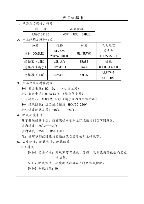
3、产品规格及特性要求
3-1 额定电压:)
3-3 耐电压:AC800V,5秒(端子及心线绝缘耐压)
3-4 绝缘阻抗:成品绝缘阻抗1MΩ/DC 250V
3-5 温度测试范围:-10℃——+60℃
5-1-3 测试结果:OK
产品规格书
1、产品品名规格、料号
料 号
品名规格
L020151126
2、产品结构及材料组成
品名
规格
材质
表面处理
线材(CABLE)
UL2725 28#*4C+D+AL
贝吉色(UL2725…)
连接器(USB)
USB A/M
BRASS
镀镍
连接器(端子)
JS2541-T
BRASS
GOLD PLALED
连接器(HSG)
USB3.0 产品规格书最新版

DOC. NO.:SPEC-USB-001 REV.:X8DATE:5/6/2011TITLE:USB3.0 AM TO uB CABLE ASSEMBLYTITLEUSB3.0 A TYPE PLUG TO micro USB3.0 B TYPE PLUG CABLE ASSEMBLYTABLE OF CONTENTS1.0 SCOPE2.0 APPLICABLE DOCUMENTS3.0 DESCRIPTION4.0 REQUIREMENTS5.0 TEST SPECIFICATIONS AND METHODS6.0 CABLE FLEXING TEST DIAGRAM7.0 HUMIDITY CONDITION8.0 TEST SEQUENCEDOC. NO.:SPEC-USB-001 REV.:X8DATE:5/6/2011TITLE:USB3.0 AM TO uB CABLE ASSEMBLY1.0 SCOPEThis product specification defines the product performance and the test methods, which includes mechanical, electrical and environmental requirements for USB3.0 A type plug to USB3.0 micro B type plug cable assembly series products.2.0 APPLICABLE DOCUMENTSThe following documents are consisting of a part of this specification. The product drawings shall take priority in events of conflict between these specification requirements and the product drawings.a) EIA-364: Electrical Conn./Socket Test Procedure Including Environmental.b) USB3.0: Universal Serial Bus 3.0 Connectors and Cable Assemblies Specificationc) QW-QA-43: ICT Internal Harmful Material and Process Control Std.3.0 DESCRIPTION3.1 CONSTRUCTIONCable assembly shall be designed, constructed and specified on the applicable drawing,3.2 MATERIALSRefer to the according BOM list, which defined in the engineering drawings4.0 REQUIREMENT4.1 GENERAL PERFORMANCE:Connector shall be defined to meet all of the requirements specified in section 5.0. Unless otherwise specified, all tests will be performed at following conditions:Temperature: 25°C +/- 10°CHumidity: 45% ~ 75%Pressure: 86 ~ 106 Kpa4.2 Current rating: 5A Max.4.3 Operating Temperature: +0°C--50°C4.4 Storage Temperature: -20°C --+60°C4.5 Marking:Only products that meet or exceed the compliance test requirements identified in this document at the time of testing are eligible to display the certified logo provided the product vendor has signed the USB IF logo trademark license agreement.5.0 TEST SPECIFICATIONS AND METHODSMethod of measuring resistance should be used to connector and assembly with USB3.0 cable, 5.1 ELECTRICAL REQUIREMENTSDOC. NO.:SPEC-USB-001 REV.:X8DATE:5/6/2011TITLE:USB3.0 AM TO uB CABLE ASSEMBLYDESCRIPTION TEST CONDITION REQUIREMENT5.1.1 Low LevelContactResistanceMeasure at 20 mV (Max) open circuit at100 mA with Mated connectors,(EIA-364-23)30 mΩ (Max) forVBUS and GND50 mΩ max forall other contactschange of delta +10mΩ max after test.5.1.2 ContactCurrentRatingA current of 1.8 A shall be applied to VBUS pinand its corresponding GND pin, a minimumcurrent of 0.25 A shall be applied to all the othercontacts.(EIA 364-70, Method 2)The delta temperatureshall not exceed +30 °Cat any point5.1.3 DielectricWithstandingVoltageApply 100 Volts AC (RMS) between adjacentcontacts of unmated and mated connectors(EIA 364-20)No breakdown shalloccur5.1.4Capacitance Test between adjacent contacts, unmatedconnector at 1 KHz.2 pF maximumD+/D- contacts only.5.1.5 InsulationResistanceApply 100 VDC for two minutes maximum, or untilstabilized between adjacent contacts of matedconnectors. (EIA 364-21)100 MΩ Min.5.1.6 Voltage Drop 5V nominal at 900mA.Apply through the mated connectors and cableBUS & GND each have225 mV max drop,5.1.7 Wiring Verify wiring to plugs to match appropriate tablesin the USB 3.0 Specification:Tables 5-9, 5-10, 5-11, 5-12 or 5-13Using an ohmmeter,verify wiring pin-to-pin5.1.8 ID PinResistanceVerify the resistance of the ID pin to ground.Micro-USB connectors onlyMust have a resistanceto ground greater than1M Ohms on the ID pin.DOC. NO.:SPEC-USB-001 REV.:X8DATE:5/6/2011TITLE:USB3.0 AM TO uB CABLE ASSEMBLY5.1.9DifferentialimpedanceMatedConnector EIA 364 – 108This test ensures that the signal conductors of theUSB 3.0 connectors have the proper impedance.(50ps rise time, 20%--80%, TDR)Mated connector includes cable termination areas90±15Ω(75Ω~105Ω)Super Speed pairs only5.1.10DifferentialimpedanceCableEIA 364 – 108This test ensures that the signal conductors of theUSB 3.0 connectors have the proper impedance.(200ps rise time, 20%--80%)90±7Ω(83Ω~97Ω)5.1.11Cross TalkDifferential Near and Far End Cross talks betweenSS Pairs and D+/D- pair of Mated Cable Assembly500ps (10-90%) rise time of a differential TDTStandard-A: 2%Micro family: 2%Near End Crosstalk between SS Pairs of MatedCable Assembly50ps (20-80%) rise time of a differential TDTSuper Speed pairs only. (EIA-360-90)Standard-A: 0.9%Micro family: 1.2%5.1.12D+/D- pairPropagationDelayD+/D- lines of the cable assembly.200 ps (10%-90%) rise time EIA 364 -10326ns max. no micro10ns max. with microD+/D-lines only5.1.13DifferentialInsertion Loss(SS)Mated Cable AssembliesNormalized with a 90-ohm differential impedance.100 MHz to 7.5 GHz (EIA-360-101)-1.5dB/cable 0.1GHz-5dB/cable 1.25GHz-7.5dB/cable 2.5GHz-25dB/cable 7.5GHz5.1.14PropagationDelay Intra-pair SkewThis test ensures that the signal on both the D+and D- lines of cable assembly arrive at thereceiver at the same time.200 ps (10%--90%) rise timeEIA 364 – 103D+/D- line: 100 ps max.5.1.15D+/D-PairAttenuation12 to 400 MHzThis test ensures the D+/D- pair of a cableassembly can provide adequate signal strength tothe receiver in order to maintain a low error rate.EIA 364 – 101-0.67 dB Max @ 12 MHz-0.95 dB Max @ 24 MHz-1.35 dB Max @ 48 MHz-1.90 dB Max @ 96 MHz-3.20 dB Max @ 200 MHz-5.80 dB Max @ 400 MHz5.1.16DifferentialCommonModeConversion(SS)Measure the single-ended S-parameters of themated cable assembly and derive the Differentialto Common Mode Conversion. See Appendix C.Normalized with a 90-ohm differential impedance.The main purpose of this requirement is to limitthe cable assembly EMI emission.100 MHz to 7.5 GHz-20dB/max @ 100MHzto 7.5GHzSuperSpeed pairs only.DOC. NO.:SPEC-USB-001 REV.:X8DATE:5/6/2011TITLE:USB3.0 AM TO uB CABLE ASSEMBLY5.2 MECHANICAL REQUIREMENTSDESCRIPTION TEST CONDITION REQUIREMENT5.2.1 AppearanceExaminationVisual inspection& DimensionalcheckingThere shall be no defects that wouldimpair normal operations anddimensions shall comply with thelatest version of USB Specification5.2.2 Insertion Force Insert connectors at a maximum rateof 12.5mm per minute. (EIA-364-13)35 N maximum5.2.3 WithdrawForceWithdraw connectors at a maximumrate of 12.5mm per minute.10N-25N at initial8N-25N after durability.No burs or sharp edges are allowedon top of locking latches5.2.4 Cable Pull- outForceClamp one end of the cable plug andapply 40N steady state axial load tothe cable for one minute.No electrical discontinuity and nophysical damage to the cableassembly shall occur5.2.5 Cable Flex Bend the cable with Dimension X =3.7 times the cable diameter and 100cycles in each of two planes. With 120degree arc. (EIA-364-41, Condition I)No physical damage or discontinuityover 1ms during flexing test.5.2.64-AxisContinuityApply 8N perpendicular force toconnection at 0, 90, 180 and 270degrees, 10 seconds duration at eachaxis. Verify electrical continuity of allpin contacts at each axis.Note: Applicable only to microconnectors with mated condition.No contact chatter greater than 1.0microsecond during 10 seconds ateach axis.Note: When testing a USB2.0 MicroUSB plug in a USB 3.0 receptacle, ifthe combination does not pass at 8Nat 180 degrees, then 7N may beused for the 180-degree direction.5.2.7Durability The durability test shall be done at amaximum rate of 200 cycles per hourmanually or 500 cycles maximumautomatically and no physicaldamage to any part of the connectorand cable assembly shall occur.(EIA-364-09)Conn Std Durability High DurabilityUSB 3.0Std-A1.5K cyclesmin5K cycles minUSB 3.0Micro B10K cyclesmin10K cycles minChange form initial value:Contact: 30 milliohm Max.Shell: 50 milliohm Max.5.2.8 Vibration EIA 364-28Test Condition VII, Test Letter DThis test procedure tests the ability ofUSB 3.0 connectors to withstandconditions involving vibration.No evidence of physical damages.Test shall be done in sequencesdefined in EIA 364-1000.01.DOC. NO.:SPEC-USB-001 REV.:X8DATE:5/6/2011TITLE:USB3.0 AM TO uB CABLE ASSEMBLY5.3 ENVIRONMENT REQUIREMENTS5.3.1 TemperatureLifeEIA 364-17, Method A.The object of this test procedure is todetail a standard method to assessthe ability of a USB 3.0 connector towithstand temperature.105º C without applied voltage for 72hours when used as preconditioningin EIA 364-1000.01.5.3.2 TemperatureShock10 Cycles –55O C and +85O C.The USB 3.0 connectors under testmust be mated.Test shall be done in sequencesdefined in EIA 364-1000.01.There shall be no evidence of anyphysical damage.5.3.3 Temperature &Humidity24 cycles as defined in Test Group 2of EIA 364-1000.01.25°C ± 3°C at 80% ± 3%RH and65°C ± 3°C at 50% ± 3%RH. Ramptimes should be 0.5 hour and dwelltimes should be 1.0 hour.There shall be no evidence of anyphysical damage.DOC. NO.:SPEC-USB-001 REV.:X8DATE:5/6/2011TITLE:USB3.0 AM TO uB CABLE ASSEMBLY6 CABLE FLEXING TEST DIAGRAM7.0 HUMIDITY CONDITIONDOC. NO.:SPEC-USB-001 REV.:X8DATE:5/6/2011TITLE:USB3.0 AM TO uB CABLE ASSEMBLY8.0 TEST SEQUENCEItem (Item NO.)GroupA B C D E F G H1 Appearance (5.2.1) 1,13 1,9 1,8 1,7 1,7 1,7 1,7 12 Dielectric WithstandingVoltage (5.1.3)2 2,7 2,6 2,5 2,5 2,5 2,5 23 Low Level Contact Resistance(5.1.5)3,124 Insertion Force (5.2.2) 7,105 Withdrawal Force (5.2.3) 8,116 Durability (5.2.7) 97 Capacitance (5.1.4) 58 Insulation Resistance (5.1.5) 4 3,8 7 3,6 3,6 3,6 3,6 39 Cable Pull Out (5.2.4) 610Cable Flex (5.2.5) 4114-Axil Continuity (5.2.6) 512Voltage Drop (5.1.6) 413 Wiring (5.1.7) 414 ID Pin Resistance (5.1.8) 515 Vibration (5.2.8) 616 Temperature life (5.3.1) 417 Temperature Humidity (5.3.3) 418 Temperature Shock (5.3.2) 419High Speed (5.1.9—5.1.16) 4 20 Sample Quantity 3pcs 3pcs3pcs3pcs3pcs3pcs3pcs3pcs。
USB数据线规格说明_
USB数据线规格说明
一、USB数据线接口spec
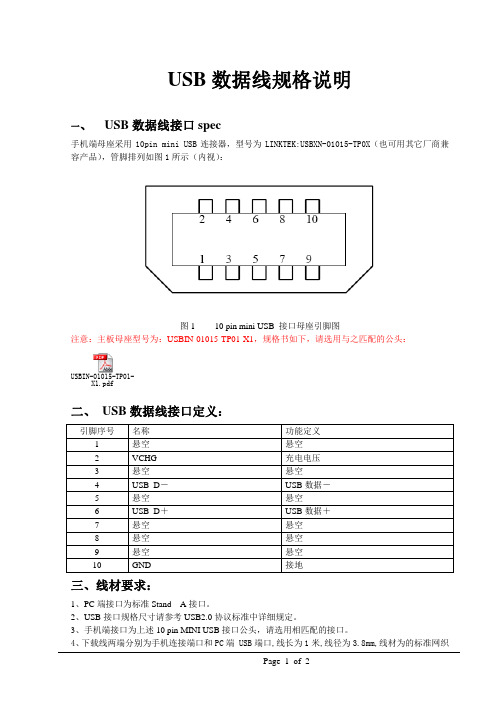
手机端母座采用10pin mini USB连接器,型号为LINKTEK:USBXN-01015-TP0X(也可用其它厂商兼容产品),管脚排列如图1所示(内视):
图1 10 pin mini USB 接口母座引脚图
注意:主板母座型号为:USBIN-01015-TP01-X1,规格书如下,请选用与之匹配的公头:
USBIN-01015-TP01-
X1.pdf
二、USB数据线接口定义:
引脚序号名称功能定义
1 悬空悬空
2 VCHG 充电电压
3 悬空悬空
4 USB_D-USB数据-
5 悬空悬空
6 USB_D+USB数据+
7 悬空悬空
8 悬空悬空
9 悬空悬空
10 GND 接地
三、线材要求:
1、PC端接口为标准Stand A接口。
2、USB接口规格尺寸请参考USB2.0协议标准中详细规定。
3、手机端接口为上述10 pin MINI USB接口公头,请选用相匹配的接口。
4、下载线两端分别为手机连接端口和PC端 USB端口,线长为1米,线径为3.8mm,线材为的标准网织
Page 1 of 2
屏蔽线,线外被及SR为75度阻燃PVC。
Page 2 of 2。
最全的USB数据线接口资料全
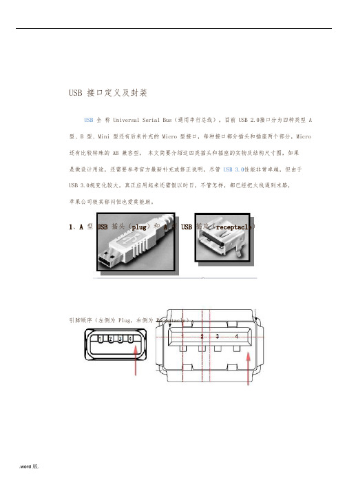
USB 接口定义及封装USB全称 Universal Serial Bus(通用串行总线),目前 USB 2.0接口分为四种类型 A 型、B 型、Mini 型还有后来补充的 Micro 型接口,每种接口都分插头和插座两个部分,Micro 还有比较特殊的 AB 兼容型,本文简要介绍这四类插头和插座的实物及结构尺寸图,如果是做设计用途,还需要参考官方最新补充或修正说明,尽管 USB 3.0性能非常卓越,但由于USB 3.0规变化较大,真正应用起来还需假以时日,不管怎样,都已经把火线逼到末路,苹果公司极其郁闷但也爱莫能助。
1、A型 USB插头(plug)和 A型 USB插座(receptacle)引脚顺序(左侧为 Plug,右侧为 Receptacle):引脚定义:编号1234 定义VBUSD-D+GND颜色识别Red(红色)White(白色)Green(绿色)Black(黑色)封装尺寸(单 PIN Receptacle):2、B型 USB插头(plug)和 B型 USB插座(receptacle)引脚顺序(左侧为 Plug,右侧为 Receptacle,注意箭头所指斜口向上,USB 端口朝向自己):引脚定义、封装尺寸均与 A 型 USB引脚说明相同。
封装尺寸(单 PIN Receptacle):3、Mini B型 USB插头(plug)和 Mini B型 USB插座(receptacle)引脚顺序(左侧为 Plug,右侧为 Receptacle,注意宽边在上,USB 端口朝向自己):引脚定义:编号12345封装尺寸(Receptacle):定义VBUSD-D+IDGND颜色识别Red(红色)White(白色)Green(绿色)Not connected(未连接)Black(黑色)以上部分为 USB 2.0规容,下面的 Micro USB 实际上是在2006年才发布的补充规,由于该接口定义无法后向支持 USB 3.0协议,故仍然归于 USB 2.0协议包。
usb 3.0规格书
Product Specifications
6.0 ELECTRICAL PERFORMANCE SPECIFICATIONS
Item Test Condition
SPEC-UB Page: 2 of 7Leabharlann Requirement Result
6.1
Low Level Contact Resistance
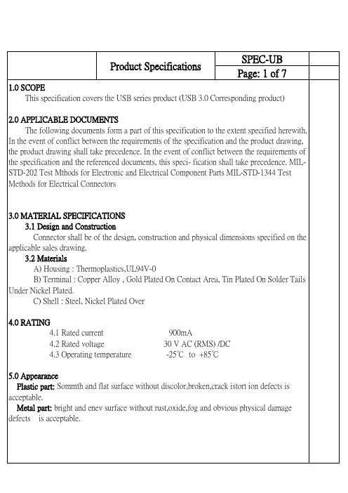
3.0 MATERIAL SPECIFICATIONS 3 3.1 Design and Construction Connector shall be of the design, construction and physical dimensions specified on the applicable sales drawing. 3.2 Materials 3.2 A) Housing : Thermoplastics,UL94V-0 B) Terminal : Copper Alloy , Gold Plated On Contact Area, Tin Plated On Solder Tails Under Nickel Plated. C) Shell : Steel, Nickel Plated Over 4.0 RATING 4.1 Rated current 900mA 4.2 Rated voltage 30 V AC (RMS) /DC 4.3 Operating temperature -25℃ to +85℃ 5.0 Appearance part: Plastic part: Sommth and flat surface without discolor,broken,crack istort ion defects is acceptable. Metal part: bright and enev surface without rust,oxide,fog and obvious physical damage Metal defects is acceptable.
- 1、下载文档前请自行甄别文档内容的完整性,平台不提供额外的编辑、内容补充、找答案等附加服务。
- 2、"仅部分预览"的文档,不可在线预览部分如存在完整性等问题,可反馈申请退款(可完整预览的文档不适用该条件!)。
- 3、如文档侵犯您的权益,请联系客服反馈,我们会尽快为您处理(人工客服工作时间:9:00-18:30)。
备注
外观
/
/
/
全检
外形尺寸
√
接触阻抗
√
绝缘阻抗
√
插入力
√
拔出力
√
保持力
√
表二
5.3 判定:当不良数超出上述规定时,判为不合格,退回重工,再按规定提交检查
6.周期试验
6
6.1 周期检查按 GB/T2829-2002 标准执行,采用判别水平 II,一次抽样方法,RQL=30
6.2 周期时机
6.2.1 批量生产前
11. 相关文件:此规范参照行业协会标准制定,当有冲突时请参照客户要求或图面为准。
当本规范与其它参考文件不一致时,请以此规范为准。
【产品工程控制程序】【模具设计制做作业指导书】【产品特性及测试标准】【文件与记录控制程序】
12. 相关表单: FAI 全尺寸报告 信耐性测试要求的表单
批准
审核
编制
文件名称
4.5
耐电压
公母配插后,施加 AC 500V 电压于相邻两 端子间 1 分钟
机械特性
4.6
插入力 以每分钟 12.5±3mm 的速度插入连接器
4.7
拔出力 以每分钟 12.5±3mm 的速度拔出连接器
端子与塑胶 以每分钟 25±3mm 的速度沿轴向拔出端
4.8
保持力 子
环境特性
4.9
耐插拔 以每分钟 30 次的速度反复插拔
文件编号
6
JC-QW-EN-08
建创电子
USB 连接器
产品规范
生效日期 版本 页码
2013-8-25 A/0 3/4
表一 5. 逐批检查
5.1 抽样方法:按 GB/T2828.1-2003 要求执行, 采用特殊检验水平 S-2, 一次抽样方法 5.2 逐批检查项目及 AQL 值
测试项目
CRI=0
AQL 值 MAX=0.65 MIN=1.5
6.2.2 关键结构,材料更改时
6.2.3 生产期满半年或产量达 1000K 时
6.2.4 停产一年以上恢复生产时
6.2.5 客户要求时
6.3 试验样品经逐批检查合格的产品中随机抽取,作为周期检验用样品,样品数总 40PCS,
分成八组试验。周期试验内容依表 1 及表 3 执行.
6.4 判定:周期试验不合格时,应立即停产,并进行分析,采取改善措施。当试验合格后
5
耐插拔
5
振动
3
物理冲击
4
抗热性
3
抗冷性
3
恒温恒湿
5
热冲击
3
可焊性
2
耐焊锡热
2
注:数字表示测试顺序
表三
8. 包装:产品使用吸塑盒包装,然后用纸箱外包装。
9. 储存:包装好的产品,应储存放在无污染,温度在-55~85℃,相对湿度不大于 80%的环
境中有序存放。
10. 运输:可用任何方式运输,防止重压,严重碰撞,淋雨,雪等。
外观无损伤 接触阻抗:30mΩ Max.
外观无损伤 接触阻抗:30mΩ Max. 接触阻抗:30mΩ Max. 绝缘阻抗:100 MΩMin. 耐电压:符合 4.5 要求
外观无损伤 接触阻抗:30mΩ Max.
沾锡面积达 95%以上 无空焊、漏焊
无起泡、翘曲、变形、变色
批准
审核
编制
建创电子
文件名称
USB 连接器
产品规范
文件编号 生效日期 版本 页码
JC-QW-EN-08 2013-8-25 A/0 1/4
1.0 目的: 规范 USB 连接器的结构设计与开发,材质定义,测试性能参数。
2.0 适用范围: 本规范适用于 USB 连接器,包括 A 型、B 型、单层、双层、插板式、焊线式、公(PLUG)、 母(SOCKET)连接器。
3. 0 权责与要求 3.1 设计与结构
产品的设计、结构和尺寸必须与图面相符。 3.2 材料和表面处理
3.2.1. 塑胶主体: PBT、PET 或其它热塑性塑料,加入 30%玻璃纤维,防火等级 UL 94-V0 3.2.2. 端子: 铜合金,镍底 80U",接触区镀金 1-30U" (可选),焊接区镀锡或锡铅 150U". 3.2.3. 外壳: 青铜或 SPCC,镀镍或锡. 3.2.4. 其它: 双层产品的中夹片使用不锈钢材质. 3.3 电气性能 3.3.1. 额定电流: 2.5A. 3.3.2. 额定电压: 30V Max. 3.3.3. 接触阻抗: 30 mΩ Max. 3.3.4. 绝缘阻抗: 1000 MΩ Min. 3.3.5. 耐电压值: 500V AC/Minute 3.4 其它技术参数 3.4.1. 耐插拔: 5000 次 3.4.2. 工作温度: -20℃ ~ 80℃ 3.4.3. 储存温度: -55℃ ~ 85℃ 3.5 性能要求及测试描述 产品必须符合表 1 的电气、机械和环境要求。 若未特别注明,所有测试都是在室温下进行。 4. 测试要求及操作程序
方能恢复生产。如属偶然因素,允许重做一次。周期试验合格可作为验收和交
货依据。
7. 测试程序 测试项目测试群1 Nhomakorabea2
3
4
5
6
7
8
测试顺序
批准
审核
编制
建创电子
文件名称
USB 连接器
产品规范
文件编号
生效日期 版本 页码
5
JC-QW-EN-08
2013-8-25 A/0 3/4
4.4
绝缘阻抗
公母配插后, 施加 DC 500V 电压于相邻两 端子间
振幅:5.35Gs RMS
4.10
振动
频率:10-55-10 Hz 每分钟
在 X、Y、Z 三个方向上各振动 15 分钟
加速度:30G
波形:半正弦波
4.11
物理冲击 周期:11 毫秒
在 X、Y、Z 三个方向各冲击 3 次
4.12
抗热性 在 60℃±3℃的环境中放置 96 小时
4.13
抗冷性 在-20℃±3℃的环境中放置 96 小时
外观及尺寸
条款 测试项目
测试方法
要求
4.1
外观检查 目视法或放大镜
无机械损伤、镀层脱落及变形等
4.2
外形尺寸 用精度为 0.02mm 的卡尺及投影机
按图面要求
电气特性
4.3
接触阻抗
公母配插后, 在开路电压为 20mV, 开路电 流为 20mA 的环境中测试
30mΩ Max.
批准
审核
编制
文件名称
文件编号
35N(3.57Kgf) Max. 10N(1.02Kgf )Min. 焊线式: 1.0Kgf Min.
外观无损伤
接触阻抗:30mΩ Max.
插入力符合 4.6 要求
拔出力符合 4.7 要求
外观无损伤
接触阻抗:30mΩ Max.
5
瞬断:1 微秒 Max.
外观无损伤 接触阻抗:30mΩ Max.
瞬断:1 微秒 Max.
JC-QW-EN-08
建创电子
USB 连接器
产品规范
生效日期 版本 页码
2013-8-25 A/0 1/4
外观检查 接触阻抗 绝缘阻抗 耐电压
1, 9 1, 5 1,9 1,5 1,6 1,3 1,3 1,6
2, 6 2, 4 2,6 2,4
2,5
3, 7
4, 8
2,4
插入力
3,7
拔出力
4,8
端子与塑胶保持力
温度:40±2℃
4.14
潮湿
相对湿度:90-95%
持续时间:168 小时
公母配插后,按以下顺序做 10 次循环:
4.15
热冲击 a)-55℃ 30 分钟
b)+85℃ 30 分钟
4.16
可焊性
焊锡时间:2.5±0.5 秒 焊锡温度:245±5℃
4.17
耐焊性
时间:10±1 秒 温度:260±5℃
1000 MΩ Min. 无放电、击穿、飞弧现象