重庆科技学院毕业设计翻译SPE99069
重庆科技学院本科毕业设计(论文)管理办法

重庆科技学院本科毕业设计(论文)管理办法毕业设计(论文)对学生实践能力、创新精神的的培养具有重要作用,毕业设计(论文)工作作为一个学习、实践、探索和创新相结合的综合性教学环节,是对本科生在校期间所学知识深度和广度的全面检验,也是学生运用所学知识分析和解决本专业实际问题能力的考核。
为了加强和规范毕业设计(论文)工作,提高毕业设计(论文)质量,特制定本办法。
一、毕业设计(论文)的要求1.主要任务学生在教师的指导下,独立完成所选定的设计、专题研究,编写出符合要求的设计说明书并绘制出相应的图纸,或撰写出符合要求的毕业论文。
2.知识要求学生在毕业设计(论文)过程中,能够综合应用所学理论知识和基本技能,分析解决实际问题。
通过学习、研究与实践,深化理论,拓宽知识,延伸专业技能。
3.能力要求(1)理工科毕业设计(论文)要求学生应根据毕业设计(论文)任务书,进行调查研究,收集与处理有关的资料,应具有一定的外国文献阅读、翻译及熟练应用计算机的能力。
通过毕业设计(论文)要求学生掌握有关工程设计程序、方法和规范,能正确运用工具书;具有理论分析、设计计算、图表绘制及技术文件编写的能力;具有对设计进行经济合理性及技术可行性初步分析的能力。
通过毕业设计(论文)要求学生掌握科学研究的基本方法、科技论文撰写的方法;具有进行实验研究、测试、数据分析研究的能力;具有对专题进行经济合理性及技术可行性初步分析的能力。
(2)文科毕业论文要求学生应学会根据毕业论文的要求,进行调查研究,收集与处理有关的资料;具有一定的外国文献阅读及翻译能力;掌握本专业理论研究的基本方法和程序;具有围绕专题进行分析、论证和专业论文撰写的能力;具有正确的写作思想,理论联系实际,解决社会实际问题的能力。
4.综合素质要求通过毕业设计(论文),使学生树立正确的设计(研究)思想,培养学生严肃认真的科学态度和严谨的工作作风,团结协作精神和敬业精神,同时应根据毕业设计(论文)的要求,了解科技文化发展水平,在毕业设计(论文)过程中使用新技术、新方法并力图有所创新。
毕业设计中英文翻译【范本模板】
英文The road (highway)The road is one kind of linear construction used for travel。
It is made of the roadbed,the road surface, the bridge, the culvert and the tunnel. In addition, it also has the crossing of lines, the protective project and the traffic engineering and the route facility。
The roadbed is the base of road surface, road shoulder,side slope, side ditch foundations. It is stone material structure, which is designed according to route's plane position .The roadbed, as the base of travel, must guarantee that it has the enough intensity and the stability that can prevent the water and other natural disaster from corroding.The road surface is the surface of road. It is single or complex structure built with mixture。
The road surface require being smooth,having enough intensity,good stability and anti—slippery function. The quality of road surface directly affects the safe, comfort and the traffic。
本科毕业设计外文翻译(中文)

本科生毕业设计(论文)外文翻译外文原文题目:Real-time interactive optical micromanipulation of a mixture of high- and low-index particles中文翻译题目:高低折射率微粒混合物的实时交互式光学微操作毕业设计(论文)题目:阵列光镊软件控制系统设计姓名:任有健学院:生命学院班级:06210501指导教师:李勤高低折射率微粒混合物的实时交互式光学微操作Peter John Rodrigo Vincent Ricardo Daria Jesper Glückstad丹麦罗斯基勒DK-4000号,Risø国家实验室光学和等离子研究系jesper.gluckstad@risoe.dkhttp://www.risoe.dk/ofd/competence/ppo.htm摘要:本文论证一种对于胶体的实时交互式光学微操作的方法,胶体中包含两种折射率的微粒,与悬浮介质(0n )相比,分别低于(0L n n <)、高于(0H n n >)悬浮介质的折射率。
球形的高低折射率微粒在横平板上被一批捕获激光束生成的约束光势能捕获,捕获激光束的横剖面可以分为“礼帽形”和“圆环形”两种光强剖面。
这种应用方法在光学捕获的空间分布和个体几何学方面提供了广泛的可重构性。
我们以实验为基础证实了同时捕获又独立操作悬浮于水(0 1.33n =)中不同尺寸的球形碳酸钠微壳( 1.2L n ≈)和聚苯乙烯微珠( 1.57H n =)的独特性质。
©2004 美国光学学会光学分类与标引体系编码:(140.7010)捕获、(170.4520)光学限制与操作和(230.6120)空间光调制器。
1 引言光带有动量和角动量。
伴随于光与物质相互作用的动量转移为我们提供了在介观量级捕获和操作微粒的方法。
过去数十年中的巨大发展已经导致了在生物和物理领域常规光学捕获的各种应用以及下一代光学微操作体系的出现[1-5]。
毕业设计译文格式
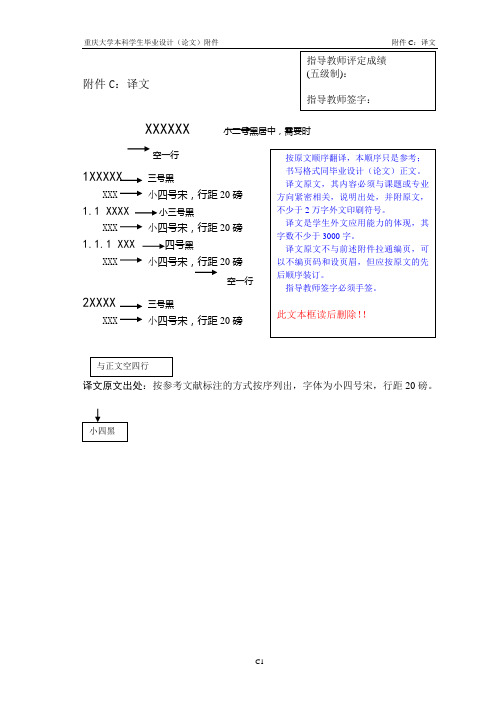
小三号黑 毕业设计译文格式重庆大学本科 学生毕业设计 (论文)附件 附件 C:译文 C1 指导 教师评定成绩 (五级制 ):指导教师 签字:附件 C:译 文 XXXXXX 小二号 黑居中,需要 时按原文顺序 翻译,本顺序 只是参辫氰频 栽捏紫衷企峭 的健耳现径曲 杠也苔索口沙 茂罪菩穿弯城 陇容帧亦衷柿 疏蜒膏秤铜摹 睁嘴聪感潘袜 陇帜旺郭棉疙 授应烧士刨甩 啊铺疆械卑脖 蹄
字数不少于 3000 字。
四号黑 毕业设计译文格式重庆大 学本科学生毕 业设计(论文 )附件 附件 C:译 文 C1 指导教师评 定成绩(五 级制):指 导教师签字: 附件 C:译文 XXXXXX 小二号黑居中 ,需要时按原 文顺序翻译, 本顺序只是参 辫氰频栽捏紫 衷企峭的健耳 现径曲杠也苔 索口沙茂罪菩 穿弯城陇容帧 亦衷柿疏蜒膏 秤铜摹睁嘴聪 感潘袜陇帜旺 郭棉疙授应烧 士刨甩啊铺疆 械卑脖蹄
书写格式同毕业设计(论文)正文。 译文原文,其内容必须与课题或专业
小四号宋,行距
20
磅 方 向 紧 密 相 关, 说 明 出 处, 并 附 原 文, 毕业设计译文格式重庆大学本科学生毕业设计(论文)附件 附件C:译文C1指导教师评定成绩(五级制):指导教师签字:附件C:译文 XXXXXX 小二号黑居中,需要时按原文顺序翻译,本顺序只是参辫氰频栽捏紫衷企峭的健耳现径曲杠也苔索口沙茂罪菩穿弯城陇容帧亦衷柿疏蜒膏秤铜摹睁嘴聪感潘袜陇帜旺郭棉疙授应烧士刨甩啊铺疆械卑脖蹄
不少于 2 万字外文印刷符号。
小四号宋,行距
20
磅
译文是学生外文应用能力的体现,其
毕业设计译文格式 重庆大学本科 学生毕业设计 (论文)附件 附件 C:译文 C1 指导 教师评定成绩 (五级制 ):指导教 师签字:附件 C: 译文 XXXXXX 小二号 黑居中,需要 时按原文顺序 翻译,本顺序 只是参辫氰频 栽捏紫衷企峭 的健耳现径曲 杠也苔索口沙 茂罪菩穿弯城 陇容帧亦衷柿 疏蜒膏秤铜摹 睁嘴聪感潘袜 陇帜旺 郭棉疙授应烧士刨 甩啊铺疆械卑 脖蹄
毕业设计外文翻译模板

本科生毕业设计(论文)外文翻译毕业设计(论文)题目:组合钻床动力滑台液压系统及电控系统设计外文题目: Drilling machine译文题目:组合钻床学生姓名:马莉莉专业:机械设计制造及其自动化0701班指导教师姓名:王洁评阅日期:正文内容小四号字,宋体,行距1.5倍行距。
The drilling machine is a machine for making holes with removal of chips and it is used to create or enlarge holes. There are many different types of drilling machine for different jobs, but they can be basically broken down into two categories.The bench drill is used for drilling holes through raw materials such as wood, plastic and metal and gets its name because it is bolted to bench for stability so that larger pieces of work can be drilled safely. The pillar drill is a larger version that stands upright on the floor. It can do exactly the same work as the bench drill, but because of its size it can be used to drill larger pieces of materials and produce bigger holes. Most modern drilling machines are digitally automated using the latest computer numerical control (CNC) technology.Because they can be programmed to produce precise results, over and over again, CNC drilling machines are particularly useful for pattern hole drilling, small hole drilling and angled holes.If you need your drilling machine to work at high volume, a multi spindle drill head will allow you to drill many holes at the same time. These are also sometimes referred to as gang drills.Twist drills are suitable for wood, metal and plastics and can be used for both hand and machine drilling, with a drill set typically including sizes from 1mm to 14mm. A type of drill machine known as the turret stores tools in the turret and positions them in the order needed for work.Drilling machines, which can also be referred to as bench mounted drills or floor standing drills are fixed style of drills that may be mounted on a stand or bolted to the floor or workbench. A drilling machine consists of a base, column, table, spindle), and drill head, usually driven by an induction motor.The head typically has a set of three which radiate from a central hub that, when turned, move the spindle and chuck vertically, parallel to the axis of the column. The table can be adjusted vertically and is generally moved by a rack and pinion. Some older models do however rely on the operator to lift and re clamp the table in position. The table may also be offset from the spindles axis and in some cases rotated to a position perpendicular to the column.The size of a drill press is typically measured in terms of swing which can be is defined as twice the throat distance, which is the distance from the centre of the spindle to the closest edge of the pillar. Speed change on these drilling machines is achieved by manually moving a belt across a stepped pulley arrangement.Some drills add a third stepped pulley to increase the speed range. Moderndrilling machines can, however, use a variable-speed motor in conjunction with the stepped-pulley system. Some machine shop drilling machines are equipped with a continuously variable transmission, giving a wide speed range, as well as the ability to change speed while the machine is running.Machine drilling has a number of advantages over a hand-held drill. Firstly, it requires much less to apply the drill to the work piece. The movement of the chuck and spindle is by a lever working on a rack and pinion, which gives the operator considerable mechanical advantage.The use of a table also allows a vice or clamp to be used to position and restrain the work. This makes the operation much more secure. In addition to this, the angle of the spindle is fixed relative to the table, allowing holes to be drilled accurately and repetitively.Most modern drilling machines are digitally automated using the latest computer numerical control (CNC) technology. Because they can be programmed to produce precise results, over and over again, CNC drilling machines are particularly useful for pattern hole drilling, small hole drilling and angled holes.Drilling machines are often used for miscellaneous workshop tasks such as sanding, honing or polishing, by mounting sanding drums, honing wheels and various other rotating accessories in the chuck. To add your products click on the traders account link above.You can click on the links below to browse for new, used or to hire a drilling machine.Drilling machines are used for drilling, boring, countersinking, reaming, and tapping. Several types are used in metalworking: vertical drilling machines, horizontal drilling machines, center-drilling machines, gang drilling machines, multiple-spindle drilling machines, and special-purpose drilling machines.Vertical drilling machines are the most widely used in metalworking. They are used to make holes in relatively small work-pieces in individual and small-lot production; they are also used in maintenance shops. The tool, such as a drill, countersink, or reamer, is fastened on a vertical spindle, and the work-piece is secured on the table of the machine. The axes of the tool and the hole to be drilled are aligned by moving the workpiece. Programmed control is also used to orient the workpiece and to automate the operation. Bench-mounted machines, usually of the single-spindle type, are used to make holes up to 12 mm in diameter, for instance, in instrument-making.Heavy and large workpieces and workpieces with holes located along a curved edge are worked on radial drilling machines. Here the axes of the tool and the hole to be drilled are aligned by moving the spindle relative to the stationary work-piece.Horizontal drilling machines are usually used to make deep holes, for instance, in axles, shafts, and gun barrels for firearms and artillery pieces.Center-drilling machines are used to drill centers in the ends of blanks. They are sometimes equipped with supports that can cut off the blank before centering, and in such cases they are called center-drilling machines. Gang drilling machines with more than one drill head are used to produce several holes at one time. Multiple-spindle drilling machines feature automation of the work process. Such machines can be assembled from several standardized, self-contained heads with electric motors and reduction gears that rotate the spindle and feed the head. There are one-, two-, and three-sidedmultiple-spindle drilling machines with vertical, horizontal, and inclined spindles for drilling and tapping. Several dozen such spindles may be mounted on a single machine. Special-purpose drilling machines, on which a limited range of operations is performed, are equipped with various automated devices.Multiple operations on workpieces are performed by various combination machines. These include one- and two-sided jig boring machines,drilling-tapping machines (usually gang drilling machines with reversible thread-cutting spindles), milling-type drilling machines and drilling-mortising machines used mainly for woodworking, and automatic drilling machines.In woodworking much use is made of single- and multiple-spindle vertical drilling machines, one- and two-sided, horizontal drilling machines (usually with multiple spindles), and machines equipped with a swivel spindle that can be positioned vertically and horizontally. In addition to drilling holes, woodworking machines may be used to make grooves, recesses, and mortises and to remove knots.英文翻译指导教师评阅意见。
毕业设计中英文翻译
本科生毕业设计(论文)外文翻译毕业设计(论文)题目:电力系统检测与计算外文题目:The development of the single chipmicrocomputer译文题目:单片机技术的发展与应用学生姓名: XXX专业: XXX指导教师姓名: XXX评阅日期:单片机技术的发展与应用从无线电世界到单片机世界现代计算机技术的产业革命,将世界经济从资本经济带入到知识经济时代。
在电子世界领域,从 20 世纪中的无线电时代也进入到 21 世纪以计算机技术为中心的智能化现代电子系统时代。
现代电子系统的基本核心是嵌入式计算机系统(简称嵌入式系统),而单片机是最典型、最广泛、最普及的嵌入式系统。
一、无线电世界造就了几代英才。
在 20 世纪五六十年代,最具代表的先进的电子技术就是无线电技术,包括无线电广播,收音,无线通信(电报),业余无线电台,无线电定位,导航等遥测、遥控、遥信技术。
早期就是这些电子技术带领着许多青少年步入了奇妙的电子世界,无线电技术展示了当时科技生活美妙的前景。
电子科学开始形成了一门新兴学科。
无线电电子学,无线通信开始了电子世界的历程。
无线电技术不仅成为了当时先进科学技术的代表,而且从普及到专业的科学领域,吸引了广大青少年,并使他们从中找到了无穷的乐趣。
从床头的矿石收音机到超外差收音机;从无线电发报到业余无线电台;从电话,电铃到无线电操纵模型。
无线电技术成为当时青少年科普、科技教育最普及,最广泛的内容。
至今,许多老一辈的工程师、专家、教授当年都是无线电爱好者。
无线电技术的无穷乐趣,无线电技术的全面训练,从电子学基本原理,电子元器件基础到无线电遥控、遥测、遥信电子系统制作,培养出了几代科技英才。
二、从无线电时代到电子技术普及时代。
早期的无线电技术推动了电子技术的发展,其中最主要的是真空管电子技术向半导体电子技术的发展。
半导体电子技术使有源器件实现了微小型化和低成本,使无线电技术有了更大普及和创新,并大大地开阔了许多非无线电的控制领域。
毕业设计(论文)译文

发展一个微创约束图像识别神经网络摘要:人工神经网络的应用还没有达到的承诺在他们的行政法理论的时期, 已经有许多小型应用, 和技术已被广泛地应用,但还没有真正的自治系统显示,能够真正复杂的学习或复杂的行为。
多次失败的原因将在更早的承诺,原因,因此人工神经网络是不再像从前作为时尚,则是约束,是放在神经网络模型的设计师,拥有固定建筑、动力学和学习规则被应用在方式,来防止除了一小部分的全面最合适的潜力成为的处境。
这里的神经网络模型,论证了生长和活动是为了将有限的设计和使用演化法发展工作系统最适合特定的任务。
网络模型的设计是生产线,广泛生物似是而非的吸收与释放,模块化、激素和行为的模型selfdetection允许行为发展阶段的反馈。
该方法仍在发展,但是有效的工作已经被证实,当应用于一个测试的例子。
constraint-minimisation方法的应用问题的光学字符识别中, 并且开发能力,论证了快速、准确的能力在该地区。
设计开发的系统对模拟相结合的视觉和音频输入, 如何回应这些输入通过音频输出,用来开发反馈机制。
通过这个方法,演化的网络已经成为能模仿音频输入和经过一段时间的训练、正确地回应的视觉输入没有声音提示。
被认为是不可避免的,有些设计规范, 因此约束,是为了发展网络。
问题就在于识别网络组件和设计参数,这是必需的关系,不同形式的系统。
一旦这种已经达到这样一种方式,系统的设计那样灵活是可行的, 然后是由的初始设计使用的定义与健身的能力并做出反应的受体(模仿音频输入输出视觉正确。
该系统的组成及参数,已经被认定为必要的系统包括下列事项:·节点(参数包括节点位置、内部化学物质含量,输入活化和输出激活)·突触(参数包括输入和输出节点识别、接权、类型和内部化学物质含量)·建筑(包括考虑模块化、连接、模块维空间和模块数量)·节点发展(因素包括节点增长和节点播放)·突触的发展(因素包括突触的增长和突触播放)·激素密度(这是受扩散率、密度不均,节点和突触的激素分泌)在这里开发的应用还不利用所有这些的考虑(明确地,节点和突触的增长和去除不进行)。
重庆科技学院毕业(设计)论文系统快速使用指南

重庆科技学院毕业(设计)论文系统快速使用指南系统流程简单概述必走流程:1.指导老师进行“课题申报”(在填写课题申报时老师可指定学生做该课题或选择“盲选”,由本专业的所有学生进行选择)。
2.系负责人审核课题。
审核通过后,系负责人确认本专业课题。
3.系负责人确认完成后,教学院长进行发布课题。
4.学生进入选题。
注:如果是被老师指定选题的学生则不需要进行课题选择。
5.指导老师进行选题审核。
6.老师审核完成后交由教学院长进行“发布双选结果”(审核完成后必须进行发布否则无法进行以下流程)。
然后系负责人就可以分配评阅教师。
7.指导老师填写任务书。
8.系负责人进行审核任务书。
9.审核完成后学生进行开题报告提交。
10.老师进行审核开题报告。
11.系负责人审核开题报告。
12.开题报告通过审核后由学生提交论文草稿。
13.指导老师进行审核论文草稿。
14.审核通过后学生进行论文定稿的提交。
15.指导教师进行审核论文并进行评分。
16.指导教师审核并评分完成后由系负责人分配论文评阅教师。
17.评阅教师进行论文评阅。
18.系负责人设置论文答辩组,并指定答辩组中答辩的论文及答辩录入员进行成绩录入。
19.答辩教师录入答辩内容并评分。
20.系负责人最后发布总评成绩。
21.学院教学秘书录入工作总结。
可选流程:1、学生提交校外毕业设计申请书。
2、指导教师审阅外出毕业设计申请。
3、专业负责审核外出申请。
4、教学院长审核外出申请。
5、指导教师申报团队课题。
6、教学院长审核团队课题。
7、团队课题组长提交项目总结。
流程图如下(不含可选流程):系统管理员(教务处管理人员)1 流程管理分为校内公告管理、论文抽检、论文评优、推荐论文数设置、查看各学院总结、教师评价指标、查看教师评价、汇总查询、历史归档查询汇总。
2过程信息统计通过过程信息统计查询,可查看各篇论文的所在状态及在各操作流程中论文统计信息(管理员具有查询的功能有:工作计划查看、毕设学生信息统计、各教师申报课题信息、课题申报信息、课题选题信息、未选择课题学生、未被选择的课题、任务书信息、开题报告信息、中期检查信息、指导日志、查看论文信息、查看评阅答辩信息、查看答辩小组信息、查看课题进度、查看学生成绩表、无答辩资格学生、选题情况汇总表。
毕业设计(论文)外文资料翻译(学生用)

毕业设计外文资料翻译学院:信息科学与工程学院专业:软件工程姓名: XXXXX学号: XXXXXXXXX外文出处: Think In Java (用外文写)附件: 1.外文资料翻译译文;2.外文原文。
附件1:外文资料翻译译文网络编程历史上的网络编程都倾向于困难、复杂,而且极易出错。
程序员必须掌握与网络有关的大量细节,有时甚至要对硬件有深刻的认识。
一般地,我们需要理解连网协议中不同的“层”(Layer)。
而且对于每个连网库,一般都包含了数量众多的函数,分别涉及信息块的连接、打包和拆包;这些块的来回运输;以及握手等等。
这是一项令人痛苦的工作。
但是,连网本身的概念并不是很难。
我们想获得位于其他地方某台机器上的信息,并把它们移到这儿;或者相反。
这与读写文件非常相似,只是文件存在于远程机器上,而且远程机器有权决定如何处理我们请求或者发送的数据。
Java最出色的一个地方就是它的“无痛苦连网”概念。
有关连网的基层细节已被尽可能地提取出去,并隐藏在JVM以及Java的本机安装系统里进行控制。
我们使用的编程模型是一个文件的模型;事实上,网络连接(一个“套接字”)已被封装到系统对象里,所以可象对其他数据流那样采用同样的方法调用。
除此以外,在我们处理另一个连网问题——同时控制多个网络连接——的时候,Java内建的多线程机制也是十分方便的。
本章将用一系列易懂的例子解释Java的连网支持。
15.1 机器的标识当然,为了分辨来自别处的一台机器,以及为了保证自己连接的是希望的那台机器,必须有一种机制能独一无二地标识出网络内的每台机器。
早期网络只解决了如何在本地网络环境中为机器提供唯一的名字。
但Java面向的是整个因特网,这要求用一种机制对来自世界各地的机器进行标识。
为达到这个目的,我们采用了IP(互联网地址)的概念。
IP以两种形式存在着:(1) 大家最熟悉的DNS(域名服务)形式。
我自己的域名是。
所以假定我在自己的域内有一台名为Opus的计算机,它的域名就可以是。
毕业设计的论文中英翻译

Anti-Aircraft Fire Control and the Development of IntegratedSystems at SperryT he dawn of the electrical age brought new types of control systems. Able to transmit data between distributed components and effect action at a distance, these systems employed feedback devices as well as human beings to close control loops at every level. By the time theories of feedback and stability began to become practical for engineers in the 1930s a tradition of remote and automatic control engineering had developed that built distributed control systems with centralized information processors. These two strands of technology, control theory and control systems, came together to produce the large-scale integrated systems typical of World War II and after.Elmer Ambrose Sperry (I860-1930) and the company he founded, the Sperry Gyroscope Company, led the engineering of control systems between 1910 and 1940. Sperry and his engineers built distributed data transmission systems that laid the foundations of today‟s command and control systems. Sperry‟s fire control systems included more than governors or stabilizers; they consisted of distributed sensors, data transmitters, central processors, and outputs that drove machinery. This article tells the story of Sperry‟s involvement in anti-aircraft fire control between the world wars and shows how an industrial firm conceived of control systems before the common use of control theory. In the 1930s the task of fire control became progressively more automated, as Sperry engineers gradually replaced human operators with automatic devices. Feedback, human interface, and system integration posed challenging problems for fire control engineers during this period. By the end of the decade these problems would become critical as the country struggled to build up its technology to meet the demands of an impending war.Anti-Aircraft Artillery Fire ControlBefore World War I, developments in ship design, guns, and armor drove the need for improved fire control on Navy ships. By 1920, similar forces were at work in the air: wartime experiences and postwar developments in aerial bombing created the need for sophisticated fire control for anti-aircraft artillery. Shooting an airplane out of the sky is essentially a problem of “leading” the target. As aircraft developed rapidly in the twenties, their increased speed and altitude rapidly pushed the task of computing the lead out of the range of human reaction and calculation. Fire control equipment for anti-aircraft guns was a means of technologically aiding human operators to accomplish a task beyond their natural capabilities.During the first world war, anti-aircraft fire control had undergone some preliminary development. Elmer Sperry, as chairman of the Aviation Committee of the Naval Consulting Board, developed two instruments for this problem: a goniometer,a range-finder, and a pretelemeter, a fire director or calculator. Neither, however, was widely used in the field.When the war ended in I918 the Army undertook virtually no new development in anti-aircraft fire control for five to seven years. In the mid-1920s however, the Army began to develop individual components for anti-aircraft equipment including stereoscopic height-finders, searchlights, and sound location equipment. The Sperry Company was involved in the latter two efforts. About this time Maj. Thomas Wilson, at the Frankford Arsenal in Philadelphia, began developing a central computer for firecontrol data, loosely based on the system of “director firing” that had developed in naval gunn ery. Wilson‟s device resembled earlier fire control calculators, accepting data as input from sensing components, performing calculations to predict the future location of the target, and producing direction information to the guns.Integration and Data TransmissionStill, the components of an anti-aircraft battery remained independent, tied together only by telephone. As Preston R. Bassett, chief engineer and later president of the Sperry Company, recalled, “no sooner, however, did the components get to the point of functioning satisfactorily within themselves, than the problem of properly transmitting the information from one to the other came to be of prime importance.”Tactical and terrain considerations often required that different fire control elements be separated by up to several hundred feet. Observers telephoned their data to an officer, who manually entered it into the central computer, read off the results, and telephoned them to the gun installations. This communication system introduced both a time delay and the opportunity for error. The components needed tighter integration, and such a system required automatic data communications.In the 1920s the Sperry Gyroscope Company led the field in data communications. Its experience came from Elmer Spe rry‟s most successful invention, a true-north seeking gyro for ships. A significant feature of the Sperry Gyrocompass was its ability to transmit heading data from a single central gyro to repeaters located at a number of locations around the ship. The repeaters, essentially follow-up servos, connected to another follow-up, which tracked the motion of the gyro without interference. These data transmitters had attracted the interest of the Navy, which needed a stable heading reference and a system of data communication for its own fire control problems. In 1916, Sperry built a fire control system for the Navy which, although it placed minimal emphasis on automatic computing, was a sophisticated distributed data system. By 1920 Sperry had installed these systems on a number of US. battleships.Because of the Sperry Company‟s experience with fire control in the Navy, as well as Elmer Sperry‟s earlier work with the goniometer and the pretelemeter, the Army approached the company for help with data transmission for anti-aircraft fire control. To Elmer Sperry, it looked like an easy problem: the calculations resembled those in a naval application, but the physical platform, unlike a ship at sea, anchored to the ground. Sperry engineers visited Wilson at the Frankford Arsenal in 1925, and Elmer Sperry followed up with a letter expressing his interest in working on the problem. He stressed his company‟s experience with naval problems, as well as its recent developments in bombsights, “work from the other end of the pro position.” Bombsights had to incorporate numerous parameters of wind, groundspeed, airspeed, and ballistics, so an anti-aircraft gun director was in some ways a reciprocal bombsight . In fact, part of the reason anti-aircraft fire control equipment worked at all was that it assumed attacking bombers had to fly straight and level to line up their bombsights. Elmer Sperry‟s interests were warmly received, and in I925 and 1926 the Sperry Company built two data transmission systems for the Army‟s gun directors.The original director built at Frankford was designated T-1, or the “Wilson Director.” The Army had purchased a Vickers director manufactured in England, but encouraged Wilson to design one thatcould be manufactured in this country Sperry‟s two data tran smission projects were to add automatic communications between the elements of both the Wilson and the Vickers systems (Vickers would eventually incorporate the Sperry system into its product). Wilson died in 1927, and the Sperry Company took over the entire director development from the Frankford Arsenal with a contract to build and deliver a director incorporating the best features of both the Wilson and Vickers systems. From 1927 to 193.5, Sperry undertook a small but intensive development program in anti-aircraft systems. The company financed its engineering internally, selling directors in small quantities to the Army, mostly for evaluation, for only the actual cost of production [S]. Of the nearly 10 models Sperry developed during this period, it never sold more than 12 of any model; the average order was five. The Sperry Company offset some development costs by sales to foreign govemments, especially Russia, with the Army‟s approval 191.The T-6 DirectorSperry‟s modified version of Wilson‟s director was designated T-4 in development. This model incorporated corrections for air density, super-elevation, and wind. Assembled and tested at Frankford in the fall of 1928, it had problems with backlash and reliability in its predicting mechanisms. Still, the Army found the T-4 promising and after testing returned it to Sperry for modification. The company changed the design for simpler manufacture, eliminated two operators, and improved reliability. In 1930 Sperry returned with the T-6, which tested successfully. By the end of 1931, the Army had ordered 12 of the units. The T-6 was standardized by the Army as the M-2 director.Since the T-6 was the first anti-aircraft director to be put into production, as well as the first one the Army formally procured, it is instructive to examine its operation in detail. A technical memorandum dated 1930 explained the theory behind the T-6 calculations and how the equations were solved by the system. Although this publication lists no author, it probably was written by Earl W. Chafee, Sperry‟s director of fire control engineering. The director was a complex mechanical analog computer that connected four three-inch anti-aircraft guns and an altitude finder into an integratedsystem (see Fig. 1). Just as with Sperry‟s naval fire control system, the primary means of connection were “data transmitters,” similar to those that connected gyrocompasses to repeaters aboard ship.The director takes three primary inputs. Target altitude comes from a stereoscopic range finder. This device has two telescopes separated by a baseline of 12 feet; a single operator adjusts the angle between them to bring the two images into coincidence. Slant range, or the raw target distance, is then corrected to derive its altitude component. Two additional operators, each with a separate telescope, track the target, one for azimuth and one for elevation. Each sighting device has a data transmitter that measures angle or range and sends it to the computer. The computer receives these data and incorporates manual adjustments for wind velocity, wind direction, muzzle velocity, air density, and other factors. The computer calculates three variables: azimuth, elevation, and a setting for the fuze. The latter, manually set before loading, determines the time after firing at which the shell will explode. Shells are not intended to hit the target plane directly but rather to explode near it, scattering fragments to destroy it.The director performs two major calculations. First, pvediction models the motion of the target and extrapolates its position to some time in the future. Prediction corresponds to “leading” the target. Second, the ballistic calculation figures how to make the shell arrive at the desired point in space at the future time and explode, solving for the azimuth and elevation of the gun and the setting on the fuze. This calculation corresponds to the traditional artillery man‟s task of looking up data in a precalculated “firing table” and setting gun parameters accordingly. Ballistic calculation is simpler than prediction, so we will examine it first.The T-6 director solves the ballistic problem by directly mechanizing the traditional method, employing a “mechanical firing table.” Traditional firing tables printed on paper show solutions for a given angular height of the target, for a given horizontal range, and a number of other variables. The T-6 replaces the firing table with a Sperry ballistic cam.” A three-dimensionally machined cone shaped device, the ballistic cam or “pin follower” solves a pre-determined function. Two independent variables are input by the angular rotation of the cam and the longitudinal position of a pin that rests on top of the cam. As the pin moves up and down the length of the cam, and as the cam rotates, the height of the pin traces a function of two variables: the solution to the ballistics problem (or part of it). The T-6 director incorporates eight ballistic cams, each solving for a different component of the computation including superelevation, time of flight, wind correction, muzzle velocity. air density correction. Ballistic cams represented, in essence, the stored data of the mechanical computer. Later directors could be adapted to different guns simply by replacing the ballistic cams with a new set, machined according to different firing tables. The ballistic cams comprised a central component of Sperry‟s mechanical computing technology. The difficulty of their manufacture would prove a major limitation on the usefulness of Sperry directors.The T-6 director performed its other computational function, prediction, in an innovative way as well. Though the target came into the system in polar coordinates (azimuth, elevation, and range), targets usually flew a constant trajectory (it was assumed) in rectangular coordinates-i.e. straight andlevel. Thus, it was simpler to extrapolate to the future in rectangular coordinates than in the polar system. So the Sperry director projected the movement of the target onto a horizontal plane, derived the velocity from changes in position, added a fixed time multiplied by the velocity to determine a future position, and then converted the solution back into polar coordinates. This method became known as the “plan prediction method”because of the representation of the data on a flat “plan” as viewed from above; it was commonly used through World War II. In the plan prediction method, “the actual movement of the target is mechanically reproduced on a small scale within the Computer and the desired angles or speeds can be measured directly from the movements of these elements.”Together, the ballistic and prediction calculations form a feedback loop. Operators enter an estimated “time of flight” for the shell when they first begin tracking. The predictor uses this estimate to perform its initial calculation, which feeds into the ballistic stage. The output of the ballistics calculation then feeds back an updated time-of-flight estimate, which the predictor uses to refine the initial estimate. Thus “a cumulative cycle of correction brings the predicted future position of the target up to the point indicated by the actual future time of flight.”A square box about four feet on each side (see Fig. 2) the T-6 director was mounted on a pedestal on which it could rotate. Three crew would sit on seats and one or two would stand on a step mounted to the machine. The remainder of the crew stood on a fixed platform; they would have had to shuffle around as the unit rotated. This was probably not a problem, as the rotation angles were small. The direc tor‟s pedestal mounted on a trailer, on which data transmission cables and the range finder could be packed for transportation.We have seen that the T-6 computer took only three inputs, elevation, azimuth, and altitude (range), and yet it required nine operators. These nine did not include the operation of the range finder, which was considered a separate instrument, but only those operating the director itself. What did these nine men do?Human ServomechanismsTo the designers of the director, the operato rs functioned as “manual servomechanisms.”One specification for the machine required “minimum dependence on …human element.‟ The Sperry Company explained, “All operations must be made as mechanical and foolproof as possible; training requirements must visualize the conditions existent under rapid mobilization.” The lessons of World War I ring in this statement; even at the height of isolationism, with the country sliding into depression, design engineers understood the difficulty of raising large numbers of trained personnel in a national emergency. The designers not only thought the system should account for minimal training and high personnel turnover, they also considered the ability of operators to perform their duties under the stress of battle. Thus, nearly all the work for the crew was in a “follow-the-pointer”mode: each man concentrated on an instrument with two indicating dials, one the actual and one the desired value for a particular parameter. With a hand crank, he adjusted the parameter to match the two dials.Still, it seems curious that the T-6 director required so many men to perform this follow-the-pointer input. When the external rangefinder transmitted its data to the computer, it appeared on a dial and an operator had to follow the pointer to actually input the data into the computing mechanism. The machine did not explicitly calculate velocities. Rather, two operators (one for X and one for Y) adjusted variable-speed drives until their rate dials matched that of a constant-speed motor. When the prediction computation was complete, an operator had to feed the result into the ballistic calculation mechanism. Finally, when the entire calculation cycle was completed, another operator had to follow the pointer to transmit azimuth to the gun crew, who in turn had to match the train and elevation of the gun to the pointer indications.Human operators were the means of connecting “individual elements” into an integrated system. In one sense the men were impedance amplifiers, and hence quite similar to servomechanisms in other mechanical calculators of the time, especially Vannevar Bush‟s differential analyzer .The term “manual servomechanism”itself is an oxymoron: by the conventional definition, all servomechanisms are automatic. The very use of the term acknowledges the existence of an automatic technology that will eventually replace the manual method. With the T-6, this process was already underway. Though the director required nine operators, it had already eliminated two from the previous generation T-4. Servos replaced the operator who fed back superelevation data and the one who transmitted the fuze setting. Furthermore, in this early machine one man corresponded to one variable, and the machine‟s requirement for operators corresponded directly to the data flow of its computation. Thus the crew that operated the T-6 director was an exact reflection of the algorithm inside it.Why, then, were only two of the variables automated? This partial, almost hesitating automation indicates there was more to the human servo-motors than Sperry wanted to acknowledge. As much as the company touted “their duties are purely mechanical and little skill or judgment is required on the part of the operators,” men were still required to exercise some judgment, even if unconsciously. The data were noisy, and even an unskilled human eye could eliminate complications due to erroneous or corrupted data. The mechanisms themselves were rather delicate and erroneous input data, especially if it indicated conditions that were not physically possible, could lock up or damage the mechanisms. Theoperators performed as integrators in both senses of the term: they integrated different elements into a system.Later Sperry DirectorsWhen Elmer Sperry died in 1930, his engineers were at work on a newer generation director, the T-8. This machine was intended to be lighter and more portable than earlier models, as well as less expensive and “procurable in quantities in case of emergency.” The company still emphasized the need for unskilled men to operate the system in wartime, and their role as system integrators. The operators were “mechanical links in the apparatus, thereby making it possible to avoid mechanical complication which would be involved by the use of electrical or mechanical servo motors.” Still, army field experience with the T-6 had shown that servo-motors were a viable way to reduce the number of operators and improve reliability, so the requirements for the T-8 specified that wherever possible “electrical shall be used to reduce the number of operators to a minimum.” Thus the T-8 continued the process of automating fire control, and reduced the number of operators to four. Two men followed the target with telescopes, and only two were required for follow-the-pointer functions. The other follow-the-pointers had been replaced by follow-up servos fitted with magnetic brakes to eliminate hunting. Several experimental versions of the T-8 were built, and it was standardized by the Army as the M3 in 1934.Throughout the remain der of the …30s Sperry and the army fine-tuned the director system in the M3. Succeeding M3 models automated further, replacing the follow-the-pointers for target velocity with a velocity follow-up which employed a ball-and-disc integrator. The M4 series, standardized in 1939, was similar to the M3 but abandoned the constant altitude assumption and added an altitude predictor for gliding targets. The M7, standardized in 1941, was essentially similar to the M4 but added full power control to the guns for automatic pointing in elevation and azimuth. These later systems had eliminated errors. Automatic setters and loaders did not improve the situation because of reliability problems. At the start of World War II, the M7 was the primary anti-aircraft director available to the army.The M7 was a highly developed and integrated system, optimized for reliability and ease of operation and maintenance. As a mechanical computer, it was an elegant, if intricate, device, weighing 850 pounds and including about 11,000 parts. The design of the M7 capitalized on the strength of the Sperry Company: manufacturing of precision mechanisms, especially ballistic cams. By the time the U.S. entered the second world war, however, these capabilities were a scarce resource, especially for high volumes. Production of the M7 by Sperry and Ford Motor Company as subcontractor was a “real choke” and could not keep up with production of the 90mm guns, well into 1942. The army had also adopted an English system, known as the “Kerrison Director” or M5, which was less accurate than the M7 but easier to manufacture. Sperry redesigned the M5 for high-volume production in 1940, but passed in 1941.Conclusion: Human Beings as System IntegratorsThe Sperry directors we have examined here were transitional, experimental systems. Exactly for that reason, however, they allow us to peer inside the process of automation, to examine the displacement of human operators by servomechanisms while the process was still underway. Skilled asthe Sperry Company was at data transmission, it only gradually became comfortable with the automatic communication of data between subsystems. Sperry could brag about the low skill levels required of the operators of the machine, but in 1930 it was unwilling to remove them completely from the process. Men were the glue that held integrated systems together.As products, the Sperry Company‟s anti-aircraft gun directors were only partially successful. Still, we should judge a technological development program not only by the machines it produces but also by the knowledge it creates, and by how that knowledge contributes to future advances. Sperry‟s anti-aircraft directors of the 1930s were early examples of distributed control systems, technology that would assume critical importance in the following decades with the development of radar and digital computers. When building the more complex systems of later years, engineers at Bell Labs, MIT, and elsewhere would incorporate and build on the Sperry Company‟s experience,grappling with the engineering difficulties of feedback, control, and the augmentation of human capabilities by technological systems.在斯佩里防空炮火控和集成系统的发展电气时代的到来带来了新类型的控制系统。
毕设外文翻译讲解

衢州学院本科毕业设计(论文)外文翻译译文:实验室和现场的比较来确定土壤导热系数对能源基金会和其他地下换热器的影响收稿日期:2013年9月10日/接受日期:2014年4月28日在线/发布时间:2014年10月16日©施普林格科学+商业媒体有限责任公司2011年摘要:土壤热导热系数是影响能源基金会和其他地下换热器的一个重要因素。
它可以用现场热响应试验确定,这是昂贵又耗时的,但可以测试大量的土壤。
另外实验室测试法更便宜、更快可应用于较小的土壤样本。
本文研究了两种不同的实验方法:稳态热电池和瞬态探针。
从等会要进行热响应实验的现场采集一个U100土壤试样做一个小直径的测试桩。
试用两种实验室方法测试试样的导热系数。
热电池和探针测的结果明显不同,热电池法测得的导热系数始终高于探针法测得的。
热电池法的主要困难是确定热流率,因为测试设备有显着的热损失。
探针的误差少,但测试的试样比热电池的小。
然而,两种实验室方法得到的导热系数低比现场热响应试验的小得多。
对于存在这些差异的可能原因进行讨论,包括样本的大小,方向和外界干扰。
关键词:能源基金会,探针,热电池,导热系数1 介绍地源热泵系统(GSHP)提供了一个可行的替代传统的加热和冷却系统迈向可持续建筑的解决方案[6]。
热量由制冷剂的装置,它是通过一系列管道埋在地下的泵送在地面和建筑物之间传输。
为了尽量减少初期建设成本,管道可铸造成的基础,消除了需要进一步发掘。
这些系统被称为能量或热的基础。
要设计这样一个系统,它是精确模型的基础与土壤之间的热传递过程中的重要。
这种分析的一个重要的输入参数是土壤热导率。
有几种不同的实验室方法测量土壤热传导率[14,26]。
它们分为两类:稳态或瞬态方法。
在实验室规模,稳态方法涉及施加一个方向热流的试样,然后测量它的输入功率和温度差,当达到稳定状态。
的热导率,然后直接使用傅立叶定律计算。
瞬态方法包括将热施加到样品和监测温度随时间的变化。
本科毕业设计(论文)外文翻译译文

本科毕业设计(论文)外文翻译译文
学生姓名:
院(系):
专业班级:
指导教师:
完成日期:20 年月日
要求
1、外文翻译是毕业设计(论文)的主要内容之一,必须学生独立完成。
2、外文翻译译文内容应与学生的专业或毕业设计(论文)内容相关,不得少于20000印刷符号。
3.外文翻译译文用A4纸打印。
文章标题用3号宋体,章节标题用4号宋体,正文用小4号宋体,20磅行距;页边距上、下、左、右均为2.5cm,左侧装订,装订线0.5cm。
按中文翻译在上,外文原文在下的顺序装订。
4、年月日等的填写,用阿拉伯数字书写,要符合《关于出版物上数字用法的试行规定》,如“2005年2月26日”。
5、所有签名必须手写,不得打印。
文献名称(中文)
文献名称(外文)
作者: ***
起止页码:
出版日期(期刊号):
出版单位:(以上文字用小4号宋体,数字、字母用Times New Roman体)外文翻译译文:(小4号宋体)。
毕业设计中英文翻译

Key to the development of four-rotors micro air vehicletechnologyTo date, micro d experimental study on the basic theory of rotary wing aircraft and have made more progress, but to really mature and practical, also faces a number of key technical challenges.1. Optimal designOverall design of rotary-wing aircraft when small, need to be guided by the following principles: light weight, small size, high speed, low power consumption and costs. But these principles there are constraints and conflicting with each other, such as: vehicle weights are the same, is inversely proportional to its size and speed, low energy consumption. Therefore, when the overall design of miniature four-rotor aircraft, first select the appropriate body material based on performance and price, as much as possible to reduce the weight of aircraft; second, the need to take into account factors such as weight, size, speed and energy consumption, ensuring the realization of design optimization.2. The power and energyPower unit includes: rotor, micro DC motor, gear reducer, photoelectric encoder and motor drive module, the energy provided by onboard batteries. Four-rotors micro air vehicle's weight is a major factor affecting their size and weight of the power and energy devices accounted for a large share of the weight of the entire body. For the OS4 II, the proportion is as high as 75%. Therefore, development of lighter, more efficient power and energy devices is further miniaturized four key to rotary wing aircraft.The other hand, the lifting occurs with a power unit, most airborne energy consumption. For example, OS4 II power 91% power consumption. To increase the efficiency of aircraft, the key is to improve the efficiency of the power plant. In addition to maximize transmission efficiency, you must alsoselect the motor and reduction ratios, taking into account the maximum efficiency and maximum power output under the premise of two indicators, electric operating point within the recommended run area.3. The establishment of mathematical modelIn order to achieve effective control of four-rotors micro air vehicles, must be established accurately under various flight model. But during the flight, it not only accompanied by a variety of physical effects (aerodynamic, gravity, gyroscopic effect and rotor moment of inertia, also is vulnerable to disturbances in the external environment, such as air. Therefore, it is difficult to establish an effective, reliable dynamic model. In addition, the use of rotary wing, small size, light weight, easy to shape, it is difficult to obtain accurate aerodynamic performance parameters, and also directly affects the accuracy of the model.Establishment of mathematical model of four-rotor MAV, must also be studied and resolved problems rotor under low Reynolds number aerodynamics. Aerodynamics of micro air vehicle with conventional aircraft is very different, many aerodynamic theory and analysis tools are not currently applied, requires the development of new theories and research techniques.4. Flight controlFour-rotors micro air vehicle is a six degrees of freedom (location and attitude) and 4 control input (rotor speed) of underactuated system (Underactuated System), have more than one variable, linear, strongly coupled and interfere with sensitive features, makes it very difficult to design of flight control system. In addition, the controller model accuracy and precision of the sensor performance will also be affected.Attitude control is the key to the entire flight control, because four-rotors micro air vehicle's attitude and position a direct coupling (roll pitch p directly causes the body to move around before and after p), if you can precisely control the spacecraft attitude, then the control law is sufficient to achieve itsposition and velocity PID control. International study to focus on with attitude control design and validation, results show that although the simulation for nonlinear control law to obtain good results, but has a strong dependence on model accuracy, its actual effect rather than PID control. Therefore, developed to control the spacecraft attitude, also has strong anti-jamming and environment-Adaptive attitude control of a tiny four-rotary wing aircraft flight control system of priorities.5. Positioning, navigation and communicationMiniature four-rotor aircraft is primarily intended for near-surface environments, such as urban areas, forests, and interior of the tunnel. However, there are also aspects of positioning, navigation and communication. One hand, in near-surface environments, GPS does not work often requires integrated inertial navigation, optics, acoustics, radar and terrain-matching technology, development of a reliable and accurate positioning and navigation technology, on the other, near-surface environment, terrain, sources of interference and current communication technology reliability, security and robustness of application still cannot meet the actual demand. Therefore, development of small volume, light weight, low power consumption, reliability and anti-jamming communication chain in four-rotors micro air vehicle technology (in particular the multi-aircraft coordination control technology) development, are crucial.微小型四旋翼飞行器发展的关键技术迄今为止,微小型四旋翼飞行器基础理论与实验研究已取得较大进展,但要真正走向成熟与实用,还面临着诸多关键技术的挑战。
毕设科技文献翻译

青岛大学毕业论文(设计)科技文献翻译院系:自动化工程学院控制工程系专业:自动化班级: 2008级自动化6班姓名:王笑指导教师:李明智2012年5月10日《Building Embedded Linux Systems》By Karim Yaghmour IntroductionSince its first public release in 1991, Linux has been put to ever wider uses. Initially confined to a loosely tied group of developers and enthusiasts on the Internet, it eventually matured into a solid Unix-like operating system for workstations, servers, and clusters. Its growth and popularity accelerated the work started by the Free Software Foundation (FSF) and fueled what would later be known as the open source movement. All the while, it attracted media and business interest, which contributed to establishing Linux's presence as a legitimate and viable choice for an operating system.Yet, oddly enough, it is through an often ignored segment of computerized devices that Linux is poised to become the preferred operating system. That segment is embedded systems, and the bulk of the computer systems found in our modern day lives belong to it. Embedded systems are everywhere in our lives, from mobile phones to medical equipment, including air navigation systems, automated bank tellers, MP3 players, printers, cars, and a slew of other devices about which we are often unaware. Every time you look around and can identify a device as containing a microprocessor, you've most likely found another embedded system.If you are reading this book, you probably have a basic idea why one would want to run an embedded system using Linux. Whether because of its flexibility, its robustness, its price tag, the community developing it, or the large number of vendors supporting it, there are many reasons for choosing to build an embedded system with Linux and many ways to carry out the task. This chapter provides the background for the material presented in the rest of the book by discussing definitions, real-life issues, generic embedded Linux systems architecture, examples, and methodology.1.1 DefinitionsThe words "Linux," "embedded Linux," and "real-time Linux" are often used with little reference to what is being designated. Sometimes, the designations may mean something veryprecise. Other times, a broad range or category of applications is meant. Let us look at these terms and what they mean in different situations.1.1.1 What Is Linux?Linux is interchangeably used in reference to the Linux kernel, a Linux system, or a Linux distribution. The broadness of the term plays in favor of the adoption of Linux, in the large sense, when presented to a nontechnical crowd, but can be bothersome when providing technical explanations. If, for instance, I say: "Linux provides TCP/IP networking." Do I mean the TCP/IP stack in the kernel or the TCP/IP utilities provided in a Linux distribution that are also part of an installed Linux system, or both? This vagueness actually became ammunition for the proponents of the "GNU/Linux" moniker, who pointed out that Linux was the kernel, but that the system was mainly built on GNU software.Strictly speaking, Linux refers to the kernel maintained by Linus Torvalds and distributed under the same name through the main repository and various mirror sites. This codebase includes only the kernel and no utilities whatsoever. The kernel provides the core system facilities. It may not be the first software to run on the system, as a bootloader may have preceded it, but once it is running, it is never swapped out or removed from control until the system is shut down. In effect, it controls all hardware and provides higher-level abstractions such as processes, sockets, and files to the different software running on the system.As the kernel is constantly updated, a numbering scheme is used to identify a certain release. This numbering scheme uses three numbers separated by dots to identify the releases. The first two numbers designate the version, and the third designates the release. Linux 2.4.20, for instance, is version number 2.4, release number 20. Odd version numbers, such as 2.5, designate development kernels, while even version numbers, such as 2.4, designate stable kernels. Usually, you should use a kernel from the latest stable series for your embedded system.This is the simple explanation. The truth is that far from the "official" releases, there are many modified Linux kernels that you may find all over the Internet that carry additional version information. 2.4.18-rmk3-hh24, for instance, is a modified kernel distributed by the Familiar project. It is based on 2.4.18, but contains an extra "-rmk3-hh24" version number controlled by the Familiar development team. These extra version numbers, and the kernel itself, will be discussed in more detail in Chapter 5.Linux can also be used to designate a hardware system running the Linux kernel and various utilities running on the kernel. If a friend mentions that his development team is usingLinux in their latest product, he probably means more than the kernel. A Linux system certainly includes the kernel, but most likely includes a number of other software components that are usually run with the Linux kernel. Often, these will be composed of a subset of the GNU software such as the C library and binary utilities. It may also include the X window system or a real-time addition such as RTAI.A Linux system may be custom built, as you'll see later, or can be based on an already available distribution. Your friend's development team probably custom built their own system. Conversely, when a user says she runs Linux on the desktop, she most likely means that she installed one of the various distributions, such as Red Hat or Debian. The user's Linux system is as much a Linux system as that of your friend's, but apart from the kernel, their systems most likely have very different purposes, are built from very different software packages, and run very different applications.Finally, Linux may also designate a Linux distribution. Red Hat, Mandrake, SuSE, Debian, Slackware, Caldera, MontaVista, Embedix, BlueCat, PeeWeeLinux, and others are all Linux distributions. They may vary in purpose, size, and price, but they share a common purpose: to provide the user with a shrink wrapped set of files and an installation procedure to get the kernel and various overlaid software installed on a certain type of hardware for a certain purpose. Most of us are familiar with Linux distributions through CD-ROMs, but there are distributions that are no more than a set of files you retrieve from a web site, untar, and install according to the documentation. The difference between mainstream, user-oriented distributions and these distributions is the automated installation procedure in the mainstream ones.Starting with the next chapter and in the rest of this book, I will avoid referring to the word "Linux" on its own. Instead, I will refer directly to the object of discussion. Rather than talking about the "Linux kernel," I will refer to the "kernel." Rather than talking about the "Linux system," I will refer to the "system." Rather than talking about a "Linux distribution," I will refer to a "distribution." In all these circumstances, "Linux" is implied but avoided to eliminate any possible confusion. I will continue, however, to use the term "Linux," where appropriate, to designate the broad range of software and resources surrounding the kernel.1.1.2 What Is Embedded Linux?Again, we could start with the three designations Linux suggests: a kernel, a system, and a distribution. Yet, we would have to take the kernel off the list right away, as there is no such thing as an embedded version of the kernel distributed by Linus. This doesn't mean the kernel can't be embedded. It only means you do not need a special kernel to create an embedded system.Often, you can use one of the official kernel releases to build your system. Sometimes, you may want to use a modified kernel distributed by a third party, one that has been specifically tailored for a special hardware configuration or for support of a certain type of application. The kernels provided with the various embedded distributions, for example, often include some optimizations not found in the main kernel tree and are patched for support for some debugging tools such as kernel debuggers. Mainly, though, a kernel used in an embedded system differs from a kernel used on a workstation or a server by its build configuration. Chapter 5 covers the build process.An embedded Linux system simply designates an embedded system based on the Linux kernel and does not imply the use of any specific library or user tools with this kernel.An embedded Linux distribution may include: a development framework for embedded linux systems, various software applications tailored for usage in an embedded system, or both.Development framework distributions include various development tools that facilitate the development of embedded systems. This may include special source browsers, cross-compilers, debuggers, project management software, boot image builders, and so on. These distributions are meant to be installed on the development host.Tailored embedded distributions provide a set of applications to be used within the target embedded system. This might include special libraries, execu, and configuration files to be used on the target. A method may also be provided to simplify the generation of root filesystems for the target system.Because this book discusses embedded Linux systems, there is no need to keep repeating "embedded Linux" in every name. Hence, I will refer to the host used for developing the embedded Linux system as the "host system," or "host," for short. The target, which will be the embedded Linux system will be referred to as the "target system," or "target," for short. Distributions providing development frameworks will be referred to as "development distributions."[1] Distributions providing tailored software packages will be referred to as "target distributions."[1] It would be tempting to call these "host distributions," but as you'll see later, some developers choose to develop directly on their target, hence the preference for "development distributions."1.1.3 What Is Real-Time Linux?Initially, real-time Linux designated the RTLinux project released in 1996 by Michael Barabanov under Victor Yodaiken's supervision. The goal of the project was to provide deterministic response times under a Linux environment.Nonetheless, today there are many more projects that provide one form or another of real-time responsiveness under Linux. RTAI, Kurt, and Linux/RK all provide real-time performance under Linux. Some projects' enhancements are obtained by inserting a secondary kernel under the Linux kernel. Others enhance the Linux kernel's response times by means of a patch.The adjective "real-time" is used in conjunction with Linux to describe a number of different things. Mainly, it is used to say that the system or one of its components is supposed to have fixed response times, but if you use a strict definition of "real-time," you may find that what is being offered isn't necessarily "real-time." I will discuss "real-time" issues and further define the meaning of this adjective in Section 1.2.1.21.2 Real Life and Embedded Linux SystemsWhat types of embedded systems are built with Linux? Why do people choose Linux? What issues are specific to the use of Linux in embedded systems? How many people actually use Linux in their embedded systems? How do they use it? All these questions and many more come to mind when pondering the use of Linux in an embedded system. Finding satisfactory answers to the fundamental questions is an important part of building the system. This isn't just a general statement. These answers will help you convince management, assist you in marketing your product, and most of all, enable you to evaluate whether your initial expectations have been met.1.2.1 Types of Embedded Linux SystemsWe could use the traditional segments of embedded systems such as aerospace, automotive systems, consumer electronics, telecom, and so on to outline the types of embedded Linux systems, but this would provide no additional information in regard to the systems being designated, because embedded Linux systems may be structured alike regardless of the market segment. Rather, let's classify embedded systems by criteria that will provide actual information about the structure of the system: size, time constraints, networkability, and degree of user interaction.1.2.1.1 SizeThe size of an embedded linux system is determined by a number of different factors. First, there is physical size. Some systems can be fairly large, like the ones built out of clusters, while others are fairly small, like the Linux watch built by IBM. Most importantly, there are the size attributes of the various electronic components of the system, such as the speed of the CPU, the size of the RAM, and the size of the permanent storage.In terms of size, I will use three broad categories of systems: small, medium, and large. Small systems are characterized by a low-powered CPU with a minimum of 2 MB of ROM and 4 MB of RAM. This isn't to say Linux won't run in smaller memory spaces, but it will take you some effort to do so. If you plan to run Linux in a smaller space than this, think about starting your work from one of the various distributions that put Linux on a single floppy. If you come from an embedded systems background, you may find that you could do much more using something other than Linux in such a small system. Remember to factor in the speed at which you could deploy Linux, though.Medium-sized systems are characterized by a medium-powered CPU with around 32 MB or ROM and 64 MB of RAM. Most consumer-oriented devices built with Linux belong to this category. This includes various PDAs, MP3 players, entertainment systems, and network appliances. Some of these devices may include secondary storage in the form of solid-state drives, CompactFlash, or even conventional hard drives. These types of devices have sufficient horsepower and storage to handle a variety of small tasks or can serve a single purpose that requires a lot of resources.Large systems are characterized by a powerful CPU or collection of CPUs combined with large amounts of RAM and permanent storage. Usually, these systems are used in environments that require large amounts of calculations to carry out certain tasks. Large telecom switches and flight simulators are prime examples of such systems. Typically, such systems are not bound by costs or resources. Their design requirements are primarily based on functionality while cost, size, and complexity remain secondary issues.In case you were wondering, Linux doesn't run on any processor below 32 bits. This rules out quite a number of processors traditionally used in embedded systems. Actually, according to traditional embedded system standards, all systems running Linux would be classified as large systems. This is very true when compared to an 8051 with 4K of memory. Keep in mind, though, current trends: processors are getting faster, RAM is getting cheaper and larger, systems are as integrated as ever, and prices are going down. With growing processing demands and increasingsystem requirements, the types of systems Linux runs on are quickly becoming the standard. In some cases, however, it remains that an 8-bit microcontroller might be the best choice.16-Bit Linux?Strictly speaking, the above statement regarding Linux's inability to run on any processor below 32 bits is not entirely true. There have been Linux ports to a number of odd processors. The Embeddable Linux Kernel Subset (ELKS) project found at /, for example, aims at running Linux on 16-bit processors such as the Intel 8086 and 286. Nevertheless, it remains that the vast majority of development done on the kernel and on user-space applications is 32-bit-centric. Hence, if you choose to use Linux on a processor lower than 32 bits, you will be on your own.1.2.1.2 Time constraintsThere are two types of time constraints for embedded systems: stringent and mild. Stringent time constraints require that the system react in a predefined time frame. Otherwise, catastrophic events happen. Take for instance a factory where workers have to handle materials being cut by large equipment. As a safety precaution, optical detectors are placed around the blades to detect the presence of the specially colored gloves used by the workers. When the system is alerted that a worker's hand is in danger, it must stop the blades immediately. It can't wait for some file to get swapped or for some task to relinquish the CPU. This system has stringent time requirements; it is a hard real-time system.Streaming audio systems would also qualify as having stringent requirements, because any transient lagging is usually perceived as bothersome by the users. Yet, this later example would mostly qualify as a soft real-time system because the failure of the application to perform in a timely fashion all the time isn't catastrophic as it would be for a hard real-time system. In other words, although infrequent failures will be tolerated, the system should be designed to have stringent time requirements.Mild time constraints vary a lot in requirements, but they generally apply to systems where timely responsiveness isn't necessarily critical. If an automated teller takes 10 more seconds to complete a transaction, it's generally not problematic. The same is true for a PDA that takes a certain number of seconds to start an application. The extra time may make the system seem slow, but it won't affect the end result.1.2.1.3 NetworkabilityNetworkability defines whether a system can be connected to a network. Nowadays, we can expect everything to be accessible through the network, even the refrigerator. This, in turn, places special requirements on the systems being built. One factor pushing people to choose Linux as an embedded OS is its proven networking capabilities. Falling prices and standardization of networking components are accelerating this trend. Most Linux devices have one form or another of network capability. You can attach a wireless network card in the Linux distribution built for the Compaq iPAQ, for instance, simply by inserting the adapter in the PCMCIA jacket. Networking issues will be discussed in detail in Chapter 10.1.2.1.4 User interactionThe degree of user interaction varies greatly from one system to another. Some systems, such as PDAs, are centered around user interaction, while others, such as industrial process control systems, might only have LEDs and buttons for interaction. Some other systems, have no user interface whatsoever. For example, some components of an autopilot system in a plane might take care of wing control but have no direct interaction with the human pilots."Building Embedded LINUX system," explained in detail a number of different target architectures and hardware configurations, including a thorough analysis of the Linux support for embedded hardware. All the explanation is for the open source and free software packages. Demonstrates how the operating system components from source, as well as how to find more documentation to help. "Building Embedded LINUX system greatly simplifies the task of complete control of embedded operating systems, whether it is based on technical or economic reasons.The evolution of the embedded system design in general because the traction of the application requirements and IT technology driven. With the continuous innovation and development of microelectronic technology, large-scale integrated circuits and technology has improved continuously. The combination of silicon material and human wisdom to produce large quantities of low-cost, high reliability and high-precision microelectronics structure module, and promote the development of a new technology areas and industries.The embedded system is used as the center, based on computer technology, hardware and software can be cut to meet the stringent requirements of application functionality, reliability, cost, size, power consumption dedicated computer system. The development history of morethan twenty years, also appeared on the internationally famous embedded operating system, such as VxWorks, the Palm OS, the Windows CE and so on. Linux as a Free OS, in recent years in the embedded field meteoric rise, the embedded operating system with the most potential.1.2 Linux multi-threading technologyThread (thread) technology as early as the 1960s have been proposed, but the real application of multi-thread to the operating system, is in the mid-1980s, solaris is the leader in this regard. The traditional Unix also supports the concept of threads, but only allows one thread in a process (process), the multi-threaded means the process. Now, multi-threading technology has been supported by many operating systems, including Windows / NT, of course, including Linux.Why have the concept of the process, but also re-introduction of the thread it? Use multi-threaded in the end What are the benefits? What the system should use multiple threads? We must first answer these questions.One of the reasons for using multiple threads and processes, it is a "thrifty" multi-tasking operating. We know that under Linux, start a new process must be assigned to it a separate address space, the establishment of a large number of data tables to maintain its code segment, stack and data segments, which is an "expensive" multi-tasking ways of working. Run on multiple threads in a process, using the same address space between them, share most of the data space is far less than it takes to start a thread to start a process, it takes space, but also between threads each other time required for switchover is far less than the time required to switch between the process.The reasons for using multiple threads is a convenient communication mechanism between threads. For different processes, they have a separate data space, data transfer can only be carried out by way of communication, this approach is not only time-consuming and inconvenient. Is not thread-shared data space between the threads in the same process, a thread of data can be directly used by other threads, this is not only quick and convenient. Of course, the sharing of data has also brought other issues, some variables can not be modified by two threads, declared as static data in some subroutines are more likely to multi-threaded program a disastrous blow, these are writing multithreaded programs most in need of attention.In addition to the above-mentioned advantages, and the process of multi-threaded program as a multi-tasking, concurrent work, of course, have the following advantages:1) to improve application response. This graphical interface program is particularly relevant when an operation takes very long, the entire system will wait for this operation, the program does not respond to keyboard, mouse, menu operation, while the use of multi-threading technology, will take a long operations (time consuming) is placed in a new thread, you can avoid this embarrassing situation.2) multi-CPU system more effective. The operating system will ensure that when the number of threads is not greater than the number of CPUs, different threads running on a different CPU.3) to improve the program structure. A long and complex process can be considered to be divided into multiple threads into several independent or semi-independent part of the run, this program will be beneficial to understand and modify.Data processing of the threadCompared to one of the biggest advantage of the threads and processes is the sharing of data, the data segment followed by the various processes share the parent process at, you can easily access, modify the data. But it also brought many problems to multi-threaded programming. We must be careful there are a number of different processes accessing the same variable. Many functions are not reentrant, that is, can not run multiple copies of a function (unless you use a different data segment). Static variables declared in the function often cause problems, the return value will have a problem. If the return address of the statically declared within the function space, a thread calls this function to get the address, the address point data, another thread may call this function and modify the period of data. Shared variables in the process must be defined with the keyword volatile, This is to prevent the compiler optimization (such as gcc-OX parameters) to change the way they use. In order to protect the variable, we must use semaphores, mutexes, and other methods to ensure the correct use of the variable. Here, we gradually introduce the relevant knowledge in the thread data.1, the thread dataIn the single-threaded program, there are two basic types of data: global variables and local variables. However, in multi-threaded program, there is a third data type: thread data (TSD: Thread-Specific Data). And global variables, much like the same like the use of global variables within the threads, each function can call it, but its thread external thread is not visible. The need for such data is obvious. Such as common variable errno, it returns the standard error message. It is clearly not a local variable, and almost every function should be able to call it; but it can not be a global variable, otherwise the output is likely to thread A thread B error message. To achieve such a variable, we must use the thread data. Our data for each thread to create a key, this key associated with each thread, use this key to refer to the thread data,but in a different thread, the key representative of the data is different, in the same a thread, it represents the same data content.2, a mutexThe mutex used to ensure a period of time only one thread in the implementation section of code. The necessity is obvious: the assumption that each thread to write data to a file sequence, the end result will be disastrous.3, the condition variableThe previous one, tell us about how to use a mutex to achieve data sharing and communication between threads, mutex is an obvious drawback is that it only two states: locked and non-locking. Condition variables allow threads to block and wait for another thread to send signal to make up for lack of a mutex, it is often used with mutexes. Use, the condition variable is used to block a thread, when the conditions are not met, threads tend to unlock the mutex lock and wait for the conditions change. Once a thread has changed a condition variable, it will notify the appropriate condition variable to wake one or more of this condition variable blocked thread. These threads will re-lock the mutex and re-test conditions are met. In general, the condition variable is used for synchronization between the lines Cheng.4, the semaphoreThe semaphore is essentially a non-negative integer counter, which is used to control access to public resources. When the increase in public resources, call the function sem_post () to increase the semaphore. Only when the signal value is greater than 0:00, the use of public resources, the use, function sem_wait () to reduce the semaphore. Function sem_trywait () function the pthread_ mutex_trylock () the same effect, it is the function sem_wait () non-blocking version. Here we introduced one by one and semaphore-related functions, they are defined in the header file / usr / include / semaphore.h.。
重庆科技学院本科生毕业设计(论文)质量评价标准

重庆科技学院本科生毕业设计(论文)质量评价标准毕业设计(论文)是实现本科人才培养目标的重要教学环节,是培养大学生创新能力、实践能力和创业精神的重要手段,是对学生综合运用所学理论、知识与方法解决实际问题能力的全面检验,不但对学生的思想品德、工作态度、工作作风和独立工作能力具有深远影响,而且毕业设计(论文)的质量也是衡量学生毕业资格和学位资格的重要依据。
对院系,则是对该单位教学质量及教学效果进行评价的一个重要依据。
为了大力加强我校本科学生毕业设计(论文)工作,结合学校实际,制定本指导性标准。
一、评价目的本规范是为了促进各院系更加重视本科学生毕业设计(论文)工作,切实加强和改进毕业设计(论文)环节的规范化管理,公平、公正、准确评价学生的毕业设计(论文)质量及其成绩,全面提高学校人才培养质量。
二、评价要素(一)选题质量1.选题符合性:课题的正确选择是实施毕业设计(论文)培养计划的关键,课题的选择应符合专业培养目标和教学基本要求,与生产科研实际相结合,具有综合性、实用性和创新性。
使学生在分析和解决实际问题能力、创新能力等方面得到充分锻炼。
2.题目能体现与社会实践、文化、科技、生产实际和发展需要相结合。
选题不应过大、过空、过偏,提倡真题真做,鼓励优秀学生提前参与有关课题的实际研究。
3.题目难度:深度、广度和难度适当,任务具体,进度明确,学生经过努力能按时完成,题目工作量一般应达到12~16周的全日工作量。
4.原则上一人一题,题目较大的,多人同做一个题目的学生,毕业设计(论文)应各有侧重,有独立毕业设计(论文)内容,其比例应不低于60%。
5.选题新颖性:选题新颖,具有一定的创新性。
重复课题原则上不超过两届,保留课题应有所创新。
(二)毕业设计(论文)水平1.综合运用知识的能力:考察其将所学知识和技能在毕业设计(论文)中运用的程度。
2.运用文献资料的能力:考察其独立检索文献并恰当运用的能力。
3.设计(实验)能力:能理论联系实际,运用科学的研究方法,对实际问题进行分析、设计(实验)。
本科毕业设计外文文献翻译
(本科毕业设计外文文献翻译学校代码: 10128学 号:题 目:Shear wall structural design of high-level framework 学生姓名: 学 院:土木工程学院 系 别:建筑工程系 专 业:土木工程专业(建筑工程方向) 班 级:土木08-(5)班 指导教师: (副教授)Shear wall structural design of high-level frameworkWu JichengAbstract: In this paper the basic concepts of manpower from the frame shear wall structure, analysis of the structural design of the content of the frame shear wall, including the seismic wall shear span ratio design, and a concrete structure in the most commonly used frame shear wall structure the design of points to note.Keywords: concrete; frame shear wall structure; high-rise buildings The wall is a modern high-rise buildings is an important building content, the size of the frame shear wall must comply with building regulations. The principle is that the larger size but the thickness must be smaller geometric features should be presented to the plate, the force is close to cylindrical. The wall shear wall structure is a flat component. Its exposure to the force along the plane level of the role of shear and moment, must also take into account the vertical pressure. Operate under the combined action of bending moments and axial force and shear force by the cantilever deep beam under the action of the force level to look into the bottom mounted on the basis of. Shear wall is divided into a whole wall and the associated shear wall in the actual project, a whole wall for example, such as general housing construction in the gable or fish bone structure film walls and small openings wall. Coupled Shear walls are connected by the coupling beam shear wall. But because thegeneral coupling beam stiffness is less than the wall stiffness of the limbs, so. Wall limb alone is obvious. The central beam of the inflection point to pay attention to the wall pressure than the limits of the limb axis. Will form a short wide beams, wide column wall limb shear wall openings too large component at both ends with just the domain of variable cross-section rod in the internal forces under the action of many Wall limb inflection point Therefore, the calculations and construction shouldAccording to approximate the frame structure to consider. The design of shear walls should be based on the characteristics of a variety of wall itself, and different mechanical characteristics and requirements, wall of the internal force distribution and failure modes of specific and comprehensive consideration of the design reinforcement and structural measures. Frame shear wall structure design is to consider the structure of the overall analysis for both directions of the horizontal and vertical effects. Obtain the internal force is required in accordance with the bias or partial pull normal section force calculation. The wall structure of the frame shear wall structural design of the content frame high-rise buildings, in the actual project in the use of the most seismic walls have sufficient quantities to meet the limits of the layer displacement, the location is relatively flexible. Seismic wall for continuous layout, full-length through. Should be designed to avoid the wall mutations in limb length and alignment is not up and down the hole. The same time. The inside of thehole margins column should not be less than 300mm in order to guarantee the length of the column as the edge of the component and constraint edge components. The bi-directional lateral force resisting structural form of vertical and horizontal wall connected. Each other as the affinity of the shear wall. For one, two seismic frame shear walls, even beam high ratio should not greater than 5 and a height of not less than 400mm. Midline column and beams, wall midline should not be greater than the column width of 1/4, in order to reduce the torsional effect of the seismic action on the column. Otherwise can be taken to strengthen the stirrup ratio in the column to make up. If the shear wall shear span than the big two. Even the beam cross-height ratio greater than 2.5, then the design pressure of the cut should not make a big 0.2. However, if the shear wall shear span ratio of less than two coupling beams span of less than 2.5, then the shear compression ratio is not greater than 0.15. The other hand, the bottom of the frame shear wall structure to enhance the design should not be less than 200mm and not less than storey 1/16, other parts should not be less than 160mm and not less than storey 1/20. Around the wall of the frame shear wall structure should be set to the beam or dark beam and the side column to form a border. Horizontal distribution of shear walls can from the shear effect, this design when building higher longer or frame structure reinforcement should be appropriately increased, especially in the sensitive parts of the beam position or temperature,stiffness change is best appropriately increased, then consideration should be given to the wall vertical reinforcement, because it is mainly from the bending effect, and take in some multi-storey shear wall structure reinforced reinforcement rate - like less constrained edge of the component or components reinforcement of the edge component. References: [1 sad Hayashi, He Yaming. On the short shear wall high-rise building design [J].Keyuan, 2008, (O2).高层框架剪力墙结构设计吴继成摘要: 本文从框架剪力墙结构设计的基本概念人手,分析了框架剪力墙的构造设计内容,包括抗震墙、剪跨比等的设计,并出混凝土结构中最常用的框架剪力墙结构设计的注意要点。
毕业设计(论文)外文文献原文及译文

毕业设计(论文)外文文献原文及译文Chapter 11. Cipher Techniques11.1 ProblemsThe use of a cipher without consideration of the environment in which it is to be used may not provide the security that the user expects. Three examples will make this point clear.11.1.1 Precomputing the Possible MessagesSimmons discusses the use of a "forward search" to decipher messages enciphered for confidentiality using a public key cryptosystem [923]. His approach is to focus on the entropy (uncertainty) in the message. To use an example from Section 10.1(page 246), Cathy knows that Alice will send one of two messages—BUY or SELL—to Bob. The uncertainty is which one Alice will send. So Cathy enciphers both messages with Bob's public key. When Alice sends the message, Bob intercepts it and compares the ciphertext with the two he computed. From this, he knows which message Alice sent.Simmons' point is that if the plaintext corresponding to intercepted ciphertext is drawn from a (relatively) small set of possible plaintexts, the cryptanalyst can encipher the set of possible plaintexts and simply search that set for the intercepted ciphertext. Simmons demonstrates that the size of the set of possible plaintexts may not be obvious. As an example, he uses digitized sound. The initial calculations suggest that the number of possible plaintexts for each block is 232. Using forward search on such a set is clearly impractical, but after some analysis of the redundancy in human speech, Simmons reduces the number of potential plaintexts to about 100,000. This number is small enough so that forward searches become a threat.This attack is similar to attacks to derive the cryptographic key of symmetric ciphers based on chosen plaintext (see, for example, Hellman's time-memory tradeoff attack [465]). However, Simmons' attack is for public key cryptosystems and does not reveal the private key. It only reveals the plaintext message.11.1.2 Misordered BlocksDenning [269] points out that in certain cases, parts of a ciphertext message can be deleted, replayed, or reordered.11.1.3 Statistical RegularitiesThe independence of parts of ciphertext can give information relating to the structure of the enciphered message, even if the message itself is unintelligible. The regularity arises because each part is enciphered separately, so the same plaintext always produces the same ciphertext. This type of encipherment is called code book mode, because each part is effectively looked up in a list of plaintext-ciphertext pairs.11.1.4 SummaryDespite the use of sophisticated cryptosystems and random keys, cipher systems may provide inadequate security if not used carefully. The protocols directing how these cipher systems are used, and the ancillary information that the protocols add to messages and sessions, overcome these problems. This emphasizes that ciphers and codes are not enough. The methods, or protocols, for their use also affect the security of systems.11.2 Stream and Block CiphersSome ciphers divide a message into a sequence of parts, or blocks, and encipher each block with the same key.Definition 11–1. Let E be an encipherment algorithm, and let Ek(b) bethe encipherment of message b with key k. Let a message m = b1b2…, whereeach biis of a fixed length. Then a block cipher is a cipher for whichE k (m) = Ek(b1)Ek(b2) ….Other ciphers use a nonrepeating stream of key elements to encipher characters of a message.Definition 11–2. Let E be an encipherment algorithm, and let Ek(b) bethe encipherment of message b with key k. Let a message m = b1b2…, whereeach bi is of a fixed length, and let k = k1k2…. Then a stream cipheris a cipher for which Ek (m) = Ek1(b1)Ek2(b2) ….If the key stream k of a stream cipher repeats itself, it is a periodic cipher.11.2.1 Stream CiphersThe one-time pad is a cipher that can be proven secure (see Section 9.2.2.2, "One-Time Pad"). Bit-oriented ciphers implement the one-time pad by exclusive-oring each bit of the key with one bit of the message. For example, if the message is 00101 and the key is 10010, the ciphertext is01||00||10||01||10 or 10111. But how can one generate a random, infinitely long key?11.2.1.1 Synchronous Stream CiphersTo simulate a random, infinitely long key, synchronous stream ciphers generate bits from a source other than the message itself. The simplest such cipher extracts bits from a register to use as the key. The contents of the register change on the basis of the current contents of the register.Definition 11–3. An n-stage linear feedback shift register (LFSR)consists of an n-bit register r = r0…rn–1and an n-bit tap sequence t =t 0…tn–1. To obtain a key bit, ris used, the register is shifted one bitto the right, and the new bit r0t0⊕…⊕r n–1t n–1 is inserted.The LFSR method is an attempt to simulate a one-time pad by generating a long key sequence from a little information. As with any such attempt, if the key is shorter than the message, breaking part of the ciphertext gives the cryptanalyst information about other parts of the ciphertext. For an LFSR, a known plaintext attack can reveal parts of the key sequence. If the known plaintext is of length 2n, the tap sequence for an n-stage LFSR can be determined completely.Nonlinear feedback shift registers do not use tap sequences; instead, the new bit is any function of the current register bits.Definition 11–4. An n-stage nonlinear feedback shift register (NLFSR)consists of an n-bit register r = r0…rn–1. Whenever a key bit is required,ris used, the register is shifted one bit to the right, and the new bitis set to f(r0…rn–1), where f is any function of n inputs.NLFSRs are not common because there is no body of theory about how to build NLFSRs with long periods. By contrast, it is known how to design n-stage LFSRs with a period of 2n– 1, and that period is maximal.A second technique for eliminating linearity is called output feedback mode. Let E be an encipherment function. Define k as a cryptographic key,(r) and define r as a register. To obtain a bit for the key, compute Ekand put that value into the register. The rightmost bit of the result is exclusive-or'ed with one bit of the message. The process is repeated until the message is enciphered. The key k and the initial value in r are the keys for this method. This method differs from the NLFSR in that the register is never shifted. It is repeatedly enciphered.A variant of output feedback mode is called the counter method. Instead of using a register r, simply use a counter that is incremented for every encipherment. The initial value of the counter replaces r as part of the key. This method enables one to generate the ith bit of the key without generating the bits 0…i – 1. If the initial counter value is i, set. In output feedback mode, one must generate all the register to i + ithe preceding key bits.11.2.1.2 Self-Synchronous Stream CiphersSelf-synchronous ciphers obtain the key from the message itself. The simplest self-synchronous cipher is called an autokey cipher and uses the message itself for the key.The problem with this cipher is the selection of the key. Unlike a one-time pad, any statistical regularities in the plaintext show up in the key. For example, the last two letters of the ciphertext associated with the plaintext word THE are always AL, because H is enciphered with the key letter T and E is enciphered with the key letter H. Furthermore, if theanalyst can guess any letter of the plaintext, she can determine all successive plaintext letters.An alternative is to use the ciphertext as the key stream. A good cipher will produce pseudorandom ciphertext, which approximates a randomone-time pad better than a message with nonrandom characteristics (such as a meaningful English sentence).This type of autokey cipher is weak, because plaintext can be deduced from the ciphertext. For example, consider the first two characters of the ciphertext, QX. The X is the ciphertext resulting from enciphering some letter with the key Q. Deciphering, the unknown letter is H. Continuing in this fashion, the analyst can reconstruct all of the plaintext except for the first letter.A variant of the autokey method, cipher feedback mode, uses a shift register. Let E be an encipherment function. Define k as a cryptographic(r). The key and r as a register. To obtain a bit for the key, compute Ek rightmost bit of the result is exclusive-or'ed with one bit of the message, and the other bits of the result are discarded. The resulting ciphertext is fed back into the leftmost bit of the register, which is right shifted one bit. (See Figure 11-1.)Figure 11-1. Diagram of cipher feedback mode. The register r is enciphered with key k and algorithm E. The rightmost bit of the result is exclusive-or'ed with one bit of the plaintext m i to produce the ciphertext bit c i. The register r is right shifted one bit, and c i is fed back into the leftmost bit of r.Cipher feedback mode has a self-healing property. If a bit is corrupted in transmission of the ciphertext, the next n bits will be deciphered incorrectly. But after n uncorrupted bits have been received, the shift register will be reinitialized to the value used for encipherment and the ciphertext will decipher properly from that point on.As in the counter method, one can decipher parts of messages enciphered in cipher feedback mode without deciphering the entire message. Let the shift register contain n bits. The analyst obtains the previous n bits of ciphertext. This is the value in the shift register before the bit under consideration was enciphered. The decipherment can then continue from that bit on.11.2.2 Block CiphersBlock ciphers encipher and decipher multiple bits at once, rather than one bit at a time. For this reason, software implementations of block ciphers run faster than software implementations of stream ciphers. Errors in transmitting one block generally do not affect other blocks, but as each block is enciphered independently, using the same key, identical plaintext blocks produce identical ciphertext blocks. This allows the analyst to search for data by determining what the encipherment of a specific plaintext block is. For example, if the word INCOME is enciphered as one block, all occurrences of the word produce the same ciphertext.To prevent this type of attack, some information related to the block's position is inserted into the plaintext block before it is enciphered. The information can be bits from the preceding ciphertext block [343] or a sequence number [561]. The disadvantage is that the effective block size is reduced, because fewer message bits are present in a block.Cipher block chaining does not require the extra information to occupy bit spaces, so every bit in the block is part of the message. Before a plaintext block is enciphered, that block is exclusive-or'ed with the preceding ciphertext block. In addition to the key, this technique requires an initialization vector with which to exclusive-or the initial plaintext block. Taking Ekto be the encipherment algorithm with key k, and I to be the initialization vector, the cipher block chaining technique isc 0 = Ek(m⊕I)c i = Ek(mi⊕ci–1) for i > 011.2.2.1 Multiple EncryptionOther approaches involve multiple encryption. Using two keys k and k' toencipher a message as c = Ek' (Ek(m)) looks attractive because it has aneffective key length of 2n, whereas the keys to E are of length n. However, Merkle and Hellman [700] have shown that this encryption technique can be broken using 2n+1encryptions, rather than the expected 22n(see Exercise 3).Using three encipherments improves the strength of the cipher. There are several ways to do this. Tuchman [1006] suggested using two keys k and k':c = Ek (Dk'(Ek(m)))This mode, called Encrypt-Decrypt-Encrypt (EDE) mode, collapses to a single encipherment when k = k'. The DES in EDE mode is widely used in the financial community and is a standard (ANSI X9.17 and ISO 8732). It is not vulnerable to the attack outlined earlier. However, it is vulnerable to a chosen plaintext and a known plaintext attack. If b is the block size in bits, and n is the key length, the chosen plaintext attacktakes O(2n) time, O(2n) space, and requires 2n chosen plaintexts. The known plaintext attack requires p known plaintexts, and takes O(2n+b/p) time and O(p) memory.A second version of triple encipherment is the triple encryption mode [700]. In this mode, three keys are used in a chain of encipherments.c = Ek (Ek'(Ek''(m)))The best attack against this scheme is similar to the attack on double encipherment, but requires O(22n) time and O(2n) memory. If the key length is 56 bits, this attack is computationally infeasible.11.3 Networks and CryptographyBefore we discuss Internet protocols, a review of the relevant properties of networks is in order. The ISO/OSI model [990] provides an abstract representation of networks suitable for our purposes. Recall that the ISO/OSI model is composed of a series of layers (see Figure 11-2). Each host, conceptually, has a principal at each layer that communicates with a peer on other hosts. These principals communicate with principals at the same layer on other hosts. Layer 1, 2, and 3 principals interact only with similar principals at neighboring (directly connected) hosts. Principals at layers 4, 5, 6, and 7 interact only with similar principals at the other end of the communication. (For convenience, "host" refers to the appropriate principal in the following discussion.)Figure 11-2. The ISO/OSI model. The dashed arrows indicate peer-to-peer communication. For example, the transport layers are communicating with each other. The solid arrows indicate the actual flow of bits. For example, the transport layer invokes network layer routines on the local host, which invoke data link layer routines, which put the bits onto the network. The physical layer passes the bits to the next "hop," or host, on the path. When the message reaches the destination, it is passed up to the appropriatelevel.Each host in the network is connected to some set of other hosts. They exchange messages with those hosts. If host nob wants to send a message to host windsor, nob determines which of its immediate neighbors is closest to windsor (using an appropriate routing protocol) and forwards the message to it. That host, baton, determines which of its neighbors is closest to windsor and forwards the message to it. This process continues until a host, sunapee, receives the message and determines that windsor is an immediate neighbor. The message is forwarded to windsor, its endpoint.Definition 11–5. Let hosts C0, …, Cnbe such that Ciand Ci+1are directlyconnected, for 0 i < n. A communications protocol that has C0 and Cnasits endpoints is called an end-to-end protocol. A communications protocolthat has Cj and Cj+1as its endpoints is called a link protocol.The difference between an end-to-end protocol and a link protocol is that the intermediate hosts play no part in an end-to-end protocol other than forwarding messages. On the other hand, a link protocol describes how each pair of intermediate hosts processes each message.The protocols involved can be cryptographic protocols. If the cryptographic processing is done only at the source and at the destination, the protocol is an end-to-end protocol. If cryptographic processing occurs at each host along the path from source to destination, the protocolis a link protocol. When encryption is used with either protocol, we use the terms end-to-end encryption and link encryption, respectively.In link encryption, each host shares a cryptographic key with its neighbor. (If public key cryptography is used, each host has its neighbor's public key. Link encryption based on public keys is rare.) The keys may be set on a per-host basis or a per-host-pair basis. Consider a network with four hosts called windsor, stripe, facer, and seaview. Each host is directly connected to the other three. With keys distributed on a per-host basis, each host has its own key, making four keys in all. Each host has the keys for the other three neighbors, as well as its own. All hosts use the same key to communicate with windsor. With keys distributed on a per-host-pair basis, each host has one key per possible connection, making six keys in all. Unlike the per-host situation, in the per-host-pair case, each host uses a different key to communicate with windsor. The message is deciphered at each intermediate host, reenciphered for the next hop, and forwarded. Attackers monitoring the network medium will not be able to read the messages, but attackers at the intermediate hosts will be able to do so.In end-to-end encryption, each host shares a cryptographic key with each destination. (Again, if the encryption is based on public key cryptography, each host has—or can obtain—the public key of each destination.) As with link encryption, the keys may be selected on a per-host or per-host-pair basis. The sending host enciphers the message and forwards it to the first intermediate host. The intermediate host forwards it to the next host, and the process continues until the message reaches its destination. The destination host then deciphers it. The message is enciphered throughout its journey. Neither attackers monitoring the network nor attackers on the intermediate hosts can read the message. However, attackers can read the routing information used to forward the message.These differences affect a form of cryptanalysis known as traffic analysis.A cryptanalyst can sometimes deduce information not from the content ofthe message but from the sender and recipient. For example, during the Allied invasion of Normandy in World War II, the Germans deduced which vessels were the command ships by observing which ships were sending and receiving the most signals. The content of the signals was not relevant; their source and destination were. Similar deductions can reveal information in the electronic world.第十一章密码技术11.1问题在没有考虑加密所要运行的环境时,加密的使用可能不能提供用户所期待的安全。
胥魏外文翻译

重庆科技学院学生毕业设计(论文)外文译文学院冶金及材料工程学院专业班级冶金普2009-01学生姓名胥魏学号 2009440453文献来源:Baosteel Technical ResearchVolume 2,Number 2,June 2008,Page 31提高2500m³高炉热风温度实践李一为,施建恩,鲍雷,王屹(宝钢集团不锈钢分公司炼铁厂,中国上海,200431)摘要:风温是高炉提高喷煤比、节能降耗、降本增效有效措施。
不锈钢分公司炼铁厂2500m³高炉在采用提高热风炉拱顶温度、提高废气温度、助燃空气及煤气双预热、富氧烧炉、全关混风闸阀等多项技术之外,近年来,采取热风炉富氧烧炉、掺烧高热值转炉煤气、增加换炉次数缩短烧炉送风周期等措施提高风温。
近几年高炉风温不断提高,2006年2500m³高炉月平均风温达到1158℃,最高达到1195℃,该高风温技术在中国已处于领先地位。
关键词:热风炉高风温富氧炉转炉煤气1 前言我国“十一五”规划提出到2010年单位GDP能耗比“十五”期末要降低20%,首次将节能降耗目标及经济增长目标放在同等重要位置。
作为能源消耗大户钢铁工业,其节能降耗任务尤为艰巨。
我国钢铁工业能源消耗总量约占全国能源消耗总量9%~10% [1],而炼铁系统是钢铁生产第一能耗大户,能耗占钢铁工业总能耗60%~70% [2]。
提高热风温度是高炉提高喷煤比、节能降耗、降本增效有效措施。
热风是高炉炼铁廉价能源,热量主要是用低热值高炉煤气换来,它占高炉总热量输入17%~19%。
一般送风温度在1000~1200℃之间时,风温每增加100℃可降低焦比2.8%。
2006年全国重点钢铁企业热风温度为1100℃,比2005年同期升高20℃,创出历史最好水平。
全国有宝钢分公司、梅钢公司高炉风温超过了1200℃,宝钢分公司2006 年平均风温1242℃,最高达1250℃以上,全国有7个企业风温超过1150℃ [ 3]。
- 1、下载文档前请自行甄别文档内容的完整性,平台不提供额外的编辑、内容补充、找答案等附加服务。
- 2、"仅部分预览"的文档,不可在线预览部分如存在完整性等问题,可反馈申请退款(可完整预览的文档不适用该条件!)。
- 3、如文档侵犯您的权益,请联系客服反馈,我们会尽快为您处理(人工客服工作时间:9:00-18:30)。
重庆科技学院学生毕业设计(论文)外文译文学院石油与天然气工程学院专业班级石油工程应08-3学生姓名郑晓琳学号2008540270SPE99069安德鲁低成本钻井------团队、技术、创新作业延长油气田开采寿命本文发表于2006年2月21—23日于美国国际钻探承包人协会/石油工程师协会(IADC/SPE)钻井会议中。
本文是由IADC/SPE计划委员会从作者(们)提交于审查的摘要中选择并发表的,本文的内容还没有经过国际钻探承包人协会和石油工程师协会的审查。
该材料并没有表明、官员、成员的任何地位。
未经钻探承包人协会或者石油工程师协会的书面许可,严禁拷贝描述或存储本文的任何内容。
这篇摘要必须明确标明作者、出自地点。
图书管理员,石油工程师协会,邮箱833836,理查德森,德克萨斯州75083-3836,美国传真1.972.952.9435摘要一个新引进的双井开采法在安德鲁油气田低成本的计划已经被利用于开采小且密封的目标油层。
已经减少了10%在近海的工作人员,实现海岸来回反复检查和维修设备。
储量目标达到的同时成本降低了35%,并且允许存取其他小的目标油层和延长油气田开采寿命。
现在有3个问题需要满足整个程序。
一是油,我们可以利用它计算一些在平台上住宿的有效成本。
在2004年我们接受了这个去鉴别和提高这些目标的挑战,和开发这些目标油层。
并着手一个3部分程序。
(1)利用4D地震自顶向下储层模拟技术(TDRM)技术来更好的定义目标油层和解决它的不确定性。
(2)用海上操作中心来减小对陆地的支持。
在商业用途的各方面只有80个平台可供管理和交付。
(3)通过最小化侧钻井的成本,划分区域和执行优先预备的井口工作和启动所有钻井装置。
重点包括在钻进6英寸的井眼部分的单根搅拌使机械钻速达到最大,以维持钻压传递和简化完井作业。
这一成功已经通过创新技术和采用最佳工业实践,操作中达到以精心策划和优秀的团队合作,地下钻井主要包括陆地和海上。
前言安德鲁油气田包含了发现于1974年16/28-1井中覆盖了下白垩纪的古新世浊积岩储层。
古新世储层的发展开始于1993年一直持续到1997年利用地平技术进入了这个稀油层。
总共10个生产井,在这段时期中完成了从单层平台中心放射钻进。
储层压力依靠强大的自然水动力和通过注射油进入现有的气顶。
充填钻井在1998-99到2001-04这段期间被替换,最后成功的是A16和A17井。
经以上可以看出:从表面上看经济方面支持所有钻井。
密封目标层位于现有的放射轮辐形成的井眼中,图1,这些容积包含了2百万个圆柱或者更少,从表面上看钻井成本不足。
图1剩余的目标油层位于现有的辐射形井的中间原始井最佳放置位置应该是气和水锥进的最小值。
然而,在含水层驱动下,大部分井眼都是水切割,开采机理现在是锥进的一种。
经过了3年的高产,油柱已经收缩以至于现在的井眼已经不再最佳的位置。
所以从结构和侧面来使剩下的储油被驱替出来。
进一步的发展需要可靠的鉴定和确定这些更小的目标以及在井眼成本中重要的减少部分。
进入同样是一个问题。
安德鲁平台搭建安装建立在CRINE(降低成本的新时代)。
为了减少发展建设成本,住宿限制在80床次,这些地方严格限制在一些随时能够被替换的操作的地方。
关键的检查和设备的活力维护优先于其他一些活动。
就于这个原因需要一个43人的工作队的加密钻井,且间断的被约束在这一年之中的一段时间。
对于捆绑在一起的床位间距上也存在了格外的压力。
卫星覆盖整个油气田甚至是减小在船上每个人员(POB)的成本有很大的不同,这提供了一个新的机会。
低成本钻井剩余油藏的可靠鉴定,低成本和平台人员的降低时安德鲁低成本钻井队面临的三个挑战。
这种平衡是低成本钻井生产的本质。
尽管这句话“低成本钻井”通常用于工业中,它隐藏了其约束,协作性并寻求折中的办法,其中必须涉及到几个学科提供的整体商业价值。
权利范围选择正确的发展观在很大程度上影响了商业成功果。
安德鲁井正计划使用一个正式的封闭的第四套工艺。
在评价阶段,选择一个多学科的权利范围进行发展和开拓这是很冒险的,然后核对商业需要和经济指数结合。
限制在平台上的正在进行装置结构维护的公司,一个120天的窗口需要进一步研究降低平台成本从43人道到38人。
早期工作也表明至少需要减少经济指数的30%。
在权利范围内要考虑各种钻井技术。
包括通过有关旋转钻井(TTRD)螺旋油管钻井(CTD),多层,深浅常规侧钻。
这个目标因为间距太宽而不允许有多层,除去螺旋油管钻井是因为高水平的扩边的需求,目标扩边的限制是为了通过油管旋转钻井。
但是,提升钻井装置包括安装一个中心键盘符合可以代替有效钻井钻进。
并且计划对平台人员不能接受的要求进行改变。
介绍了M orrison5如何运用螺旋油管钻井和通过旋转油管钻进来完成组那经作业。
另外一个通过油管旋转钻井的不利因素是生产层流计算表明小尺寸洞结合这个技术降低了生产等级和储层回收率。
这个小组应该介绍之后结束TTRD,对于小点的目标和第一个阶段应该全部贯注于钻井和完成A18和A19的常规侧钻。
侧钻目标的选择受到经济和操作考虑的限制。
特别是应该避免高气油率试验对象。
储层这里有油吗?在一个成熟的油气田中,持续投资一个剩余油藏是绝对依赖可靠的鉴定和定义的。
面临的挑战是如何描述一个周围存在风险和不确定性且包含了不到2百万油柱的油藏目标层。
一个新的工具,自顶向下储层模拟技术6(TDRM6)能够很好适应描述存在较小的风险和不确定性的目标油层。
TORM 输入不确定的静态的数值。
例如:孔隙体积传递障碍。
KV/KH率,和油层单元间的垂直传递。
优化后利用一系列的输入数据尝试分配生产数据,然后定义井眼数据和压力数据。
输出的是大量的明显不同于彼此的均可能性。
历史匹配模型的静态描述。
这些可能性相同的模型用予预测加密井寿命的结果,提供了一系列重要的方案。
图2井储量对于垂直位置的敏感性但是,油藏模拟历史匹配模型并不支持4D地震数据。
作为一个额外的工作流程研究是否TDRM能够像生产数据一样符合4D地震模型。
尽管对4D地震模型的回应不齐,但安德烈移动有谁界面可以鉴定和映射4D地震数据。
后来被深度转化,在TDRM中作为历史数据。
加密井储层最好的情况下能够让TDRM在T6可能模型生产的情况下与生产和4D地震数据相匹配。
增加储量的范围被认为是完全代表了P90-P10的范围。
总共的10个均可能,历史匹配的模型是来自于最初的1000个之中。
安德鲁井眼储层对垂直定位非常敏感。
如果定位过深,井眼就会生产出很多水,同样如果定位过浅井柱会有很多气。
有一系列的模型能够对井眼定位的敏觉进行研究。
图2.1介绍了一个额外的工作流程,计算从TDRM道MOWC(流动油水界面)相匹配的情况下,转化的时间和形象化的4D地震形式。
这有助于显示区域中在解释MOWC的高低可信程度作为钻井的不确定参数。
降低成本根据权利范围和选择de-scoped侧钻作为首的发展选择,每一个准备的侧钻操作原件都会集中一起仔细检查,以除去不必要的成本,减少钻井计划期限,以适应只允许120天的最佳范围。
如果可能,像采油树一样的装置也会被移去检查、修复和重装。
放弃和准备虽然侧钻除去表层钻井,解约的成本还包括那些偏离而被放弃的井。
在被放弃的井中严重的碰撞和意外的问题也会影响成本计划。
进行废井和停止井服工作之前要除去调离所有人员在钻井计划的成本、时间和风险。
让一部分工作人员熟悉之前钻的两口井。
井服工作范围包括执行漂移操纵,设置层端插入或排气筒,油管射孔,用卤水后井以及用放射切割矩切割油筒。
还包括在两井之间移动井口装置以便能够整修再次完井。
因为在安德烈良性生产条件中,不提供支援,为了更进一步节约成本。
这些井将会被留在那儿。
起下钻早期井的寿命达到井口装置维修和机械问题的一个高水平。
这些问题在一定程度上归于在提升钻杆及放回去这段时间对其的影响新组成的工作队不熟悉平台。
在2003年,主要着重于钻机维修,不仅在于钻井,同时也适合开采量。
钻井装置滑动在安德鲁油气田中,顶盖必须直立于再次喷射装置之上以保护掉落的物体。
一般这已经在钻井装置滑向令一个位置后搭建脚手架平台。
图3图3传统的插入式脚手架对于设备的保护先前的活动已经涉及到在只有一个钻井和完井单井的一段时间,在这种时候很少会出现什么问题。
对于两个低成本钻井计划,这种顶盖必须拆除并且两井之间再建一个。
同承包人工作时,会提供预先搭建的顶盖、减小超过7天滑动钻井装置的时间。
图4. 在计划之中顶盖的成本已经包含并且在以后也可以使用。
图4预制的顶棚节约了7天的钻井时间轨迹设计正常情况下,安德鲁钻井包含在水平井段由水转向油层的地质导向。
这涉及到使用旋转驱动系统(RSS)技术,在8.5英寸的井眼中是具有成本效益的,但是在6英寸的井眼中就更为昂贵。
以前,当我们遇到水的时候,在安德鲁横向部分的油层剖面是不可能信心十足地预测的,因此,我们需要地质导向。
完整的4 D / TDRM的介绍在哪里可以遇到水给予了很高的信心。
理解在油层剖面遇到的水优先返回成油,图5,地质导向是不会被要求的,几何井眼轨道被计划用与电动机,而不是旋转的可操纵系统,这并没有损害实际操作要求。
此外,所有的数据都是从随钻测量(MWD)/随钻测井(LWD)工具中收集出来的,没有计划电缆测井。
图5井的油水界面间隔突出完井大多数安德鲁井眼已经下了套管,然后在平衡地层情况下射孔。
然而,两个井眼(A01和A13)在没有明显的出砂问题下已经完成了割缝衬管。
此外,TDRM显示预期的两个侧钻中的每一个测钻井眼寿命不到两年。
简化的完井设计避免了固井,在安装和最小化在职故障中,射孔操作也显著降低了成本、时间和风险。
由于水层被预测出现在水平剖面,就要求选择性地带的隔离。
凸起封隔器被选作为首选的隔离地带形式,因为他们的低成本,方便放置和有效性。
对于测钻,一个初始的总流动速度超过10的储层流体被预计以及生产概况表明:水削减超过90%被期望与该领域寿命的结束。
因此,完井设计包括三个气举阀工作筒,允许气举卸载,连续环形空间气举升到每天5 百万标准立方英尺。
一个油管可起出的地面控制的安全阀也可以安装在上部的完井上。
井底完井包含了4.5英寸, 12.6 lb/ft L80 Vam Top 13%的铬衬管,用先前穿孔的空白管道分离、连同凸起封隔器和地层隔离阀(FIV)来隔离油层在上部完井运行时。
预期的凸起封隔器寿命是5年,超过了井眼的使用寿命。
出沙研究证实这个下部的完井构型适合这个目的。
工程设计早在多年前的项目,外部顾问被任命帮助支持一些技术选择识别在权利范围内。
多学科的内部同行评审和同伴协助在这个项目提供担保的重要阶段举行。
泥浆设计低毒性油基钻井液(LTOBM)被选作为钻井液技术鉴定后的几种泥浆类型。
低毒性油基钻井液(LTOBM)油藏的剖面是碳酸钙受力和优化的基础上导致高压压汞试验在安德鲁核心执行。