安科瑞温湿度控制器安装使用说明书
安科瑞电气股份有限公司ASD开关柜综合测控装置ASD100-ASD320安装使用说明书

032ASD开关柜综合测控装置ASD switch cabinet integrated measuringand control device安装使用说明书V3.6Installation and operation instruction V3.6安科瑞电气股份有限公司Acrel Electric Co., Ltd.1安装使用指南1 Installation and operation guide1.1产品概述1.1 Product overviewASD系列开关柜综合测控装置用于3~35kV户内开关柜,适用于中置柜、手车柜、固定柜、环网柜等多种开关柜。
具有一次回路模拟图及开关状态指示,高压带电显示及核相,自动温湿度控制,加热回路故障告警,无线测温,人体感应自动照明,语音提示,电参数测量及RS485通讯接口等众多功能,集操作、显示于一体。
产品按功能分为ASD100、ASD100G、ASD200、ASD300、ASD310、ASD320六种型号。
ASD series switch cabinet integrated measuring and control device is used for 3-35kV indoor switch cabinet, applying to centrally installed switchgear, trolley cabinet, fixed switchgear, ring main unit and other various switch cabinets. With primary circuit mimetic diagram and switch status indicator, HV live displaying and nuclear phase, automatic temperature and humidity control, heating circuit fault alarm, wireless temperature measurement, body induction auto lighting, voice prompt, electrical parameter measurement and RS485 communication interface and other numerous functions, it has integrated operation and display into one. The product is classified into ASD100, ASD100G, ASD200, ASD300, ASD310, ASD320 six models according to its function.1.2型号说明1.2 Description of types图1.1 ASD系列产品命名规则Figure1.1 ASD Series Product naming rule1.3产品型号及功能1.3 Product model and function表1 ASD系列产品型号及功能Table1 ASD Series Product specification and functions 112mm×172mm 220mm×165mm无线测温Wireless temperature measurement 无None 无None可选Optional无None 可选Optional主回路电力参数测量Measure and display of power parameter 无None 无None标配Standard无NoneRS485通讯接口Communicationport无None 标配Standard1.4技术指标1.4 Technical indexes表2 ASD系列技术指标Table2 ASD Series Technical data项目Item指标ValueASD100/ASD100GASD200 ASD300 ASD310 ASD320额定输入Rated input接线方式Wiring mode————3P3L或3P4L3P3L or3P4L————电压V oltage————100V ————电流Current————5A ————频率frequency————50Hz ————准确度Accuracy rating电流、电压V oltage、Current————0.5级0.5 class————有功功率Active power无功功率Reactive power————1级1 class————电能Energy————1级1 class————环境温度Environmenttemperature±2℃±1℃相对湿度Relative humidity±10% ±5%装置工作电源Device Working powerAC 85~265V,DC 100~300V功耗Power consumption辅助电源Auxiliary power≤5V A ≤6V A ≤8V A电压输入V oltage input————≤0.5V A ——1.5产品安装 1.5 Product installationASD 系列开关柜综合测控装置采用面板嵌入式安装,首先柜体盘面上制作规定尺寸的长方形槽孔,装置取下支架后嵌入槽孔,再用支架固定即可。
安科瑞DDSD1352说明书V1.0

DDSD1352-KCSH单相电子式多功能电能表安装使用说明书V1.0 上海安科瑞电气股份有限公司一、概述DDSD1352单相电子式多功能电能表主要用于计量低压网络的单相有功电能,同时可测量电压、电流、功率等电参量,并带有通信及预付费功能,方便用户进行用电监测、集抄和预付费管理。
产品具有精度高、体积小、安装方便等优点。
可灵活安装于配电箱内,实现对不同区域和不同负荷的分项电能计量,统计和分析。
二、主要功能功能名称功能说明功能配置电能计量总电能计量(反向计入正向)■电量测量U、I 、P、Q、S、PF、F测量■LCD显示6位段式LCD显示■按键编程可设置密码、通信规约、地址、波特率等■预付费报警及跳闸远程预付费,实现先交费后用电可配合预付费专用断路器实现负载断送电控制■通信RS485接口,MODBUS-RTU或DLT645-97规约■三、技术参数电气特性电压输入工作电压范围220Vac±20%参比频率50Hz功耗<2V A电流输入基本电流10A最大电流60A起动电流40mA功耗<1V A (最大电流)测量性能符合标准GB/T17215-2002GB/T17215.211-2006GB/T15284-2002测量精度 1.0级测量范围0000.00~999999kWh时钟精度误差≤0.5s/d脉冲输出输出类型无源输出,外接电源DC+5V~24V脉冲宽度 80±20ms脉冲常数1600imp/kWh ,LED 同步指示通信接口 RS485(A+、B-) 介质 屏蔽双绞线协议MODBUS-RTU 或DLT645-1997机械特性外形尺寸 长×宽×高 36mm×86mm×62mm (2模数) 最大接线能力柔性电缆16mm 2环境条件温度范围工作温度 -20℃~60℃ 存储温度-30℃~70℃ 湿度≤95%(无凝露)四、外形尺寸五、接线与安装电能表采用35mm 标准导轨安装方式。
安科瑞电气 ARTM系列温度巡检仪 说明书

二 操作指南 1 显示介绍
1.1 ARTM1 的面板图示
1
℃
2
3
AL1
4
AL2
SET
编号
名称
状态示例
1
LEDA
0028
2
LEDB
0100
3
AL1
指示灯点亮
4
AL2
指示灯点亮
5
SET
按键按下
6
左方向键
按键按下
7
右方向键
按键按下
8
ENTER 键 按键按下
1.2 ARTM8 的面板图示
1
2
5678
说明 显示当前测得的温度值,单位℃,4 位数码管,分辨率±1℃
设定静态显示,在正常模式下按住左或右键不放,可快速切换到需要的通道温度显示,并保持。
设定循环显示,在正常模式下按住右键不放,可加快循环显示速度。
(4)“bUS”状态设置
进入系统设置模式以后,按左或右方向键直到显示“bUS”,即通讯设定,回车确认后显示“Addr”状态,再
次回车后就可以设置地址的值,通过左或右方向键改变地址值,按回车确认后返回“Addr”状态,按左或右方向
3 技术参数
技术指标 功能
最大测量通道数 输入信号 精度等级
辅 助 电压范围 电源 功 耗 报警 路 数 输出 容 量
协议 通讯 接 口
波特率 工频耐压
温度 环境 适 度
海拔
ARTM1 1
指标
ARTM8 8
热电阻:Pt100,Cu50 0.5 级
AC85~265V,DC100~350V ≤2W
2 组常开 AC250V/5A,DC30V/5A
4~20mA 及 0~5V 等;
温控器说明书
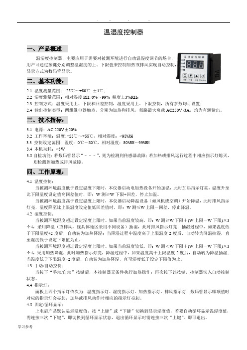
温湿度控制器一、产品概述温湿度控制器,主要应用于需要对被测环境进行自动温湿度调节的场合,用户可通过按键分别调整温湿度的上、下限值来控制加热或排风实现自动控制,显示方式为数码管显示。
二、基本功能:2.1 温度测量范围:-25℃~+80℃±1℃;2.2 湿度测量范围:相对湿度RH: 0%~99% 精度±3%RH;2.3 控制方式:温度采用上、下限和回差控制,湿度采用上、下限控制,所有参数均可设置;2.4 输出控制类型:两组继电器触点,分别为加热和排风,每路最大负载AC250V /3A,均为有源输出。
三、技术指标:3.1电源:AC 220V±20%3.2 工作环境:温度:-25℃~+55℃,相对湿度:<95%RH3.3控制设定范围:温度:0℃~80℃,相对湿度:50%RH~99%RH3.4 本机功耗:<3W3.5自检功能:若数码管显示“–––”,则为检测到传感器故障;若加热或排风运行过程中相应指示灯熄灭,则检测到加热或排风故障。
四、工作原理:4.1 温度控制:当被测环境温度低于设定温度下限时,本仪器启动电加热设备开始加温,此时加热指示灯亮,温度升至比下限温度设定值高回差值时,即:W测≥W下限+回差,停止加温。
当被测环境温度高于设定温度上限时,本仪器启动降温设备(如风机或空调)开始降温,此时排风指示灯亮,温度降至比上限温度设定值低回差值时,即:W测≤W上限-回差,停止降温。
4.2 湿度控制:当被测环境湿度超过设定湿度上限时。
如果当前温度较高,即:W测≥W下限+(W上限-W下限)×3÷4,采用降温(或排风,视具体地区采用不同设备)抽湿,此时排风指示灯亮;抽湿过程中,如果温度低于下限温度+2度后,自动转为加热降湿;当降湿过程中温度高于上限温度-2度后,自动转为降温抽湿,直至湿度低于设定下限值为止。
当被测环境湿度超过设定湿度上限时。
如果当前温度较低,即:W测<W下限+(W上限-W下限)×3÷4,采用加热降湿,此时加热指示灯亮,降湿过程中,如果温度高于上限温度-2度后,自动转为降温抽湿;当温度低于下限温度+2度后,自动转为加热降湿,直至湿度低于设定下限值为止。
安科瑞 AM2SE 系列微机保护装置 安装使用说明书
393AM2SE系列微机保护测控装置安装使用说明书V1.0安科瑞电气股份有限公司申明版权所有,未经本公司之书面许可,此手册中任何段落,章节内容均不得被摘抄、拷贝或以任何形式复制、传播,否则一切后果由违者自负。
本公司保留一切法律权利。
本公司保留对本手册所描述之产品规格进行修改的权利,恕不另行通知。
订货前,请垂询当地代理商以获悉本产品的最新规格。
目录第一章使用说明 (1)1装置介绍 (1)1.1概述 (1)1.2特点 (1)1.3装置功能对照表 (2)1.4装置选型表 (3)2技术参数 (3)2.1额定参数 (3)2.2主要技术性能 (4)2.3正常工作环境条件 (4)2.4绝缘性能 (4)2.5电磁兼容性能 (5)3装置操作说明 (5)3.1前面板说明 (5)3.2按键说明 (5)3.3菜单说明 (5)4装置外形尺寸及安装方法 (12)4.1外形及开孔尺寸 (12)4.2安装方法 (13)5装置事件记录清单 (14)第二章技术说明 (26)1功能简介 (26)2保护原理 (27)3定值表 (36)4接线方式 (41)5调试方法 (42)6二次原理图 (48)7维护及其他问题处理 (51)附录1AM5-FT防跳模块 (52)附录2遥信量名字映射表 (54)第一章使用说明1装置介绍1.1概述AM2SE系列微机保护装置集保护、控制于一体,可满足客户20KV及以下电压等级用电系统对电力能源安全运行、可靠性的保障要求。
目前广泛使用在变电站、工矿企业、医院、学校、商业广场以及大型楼宇等配网用电系统中。
保护装置采用先进成熟可靠的保护原理和算法,抗干扰性能强,可靠性高,保护实现方式灵活,通讯采用冗余设计。
装置具备8路开关量采集和5路继电器输出,能与Acrel-2000Z 电力监控软件配合,可以实现无人值班的终端用户变电站配电自动化系统。
1.2特点成熟完善的保护功能:保护装置针对不同一次设备可以灵活配置不同的保护功能,可以实现20kV以下电压等级变配电站保护控制功能,适用于线路、母联、配电变压器等设备的保护和自动控制功能。
温湿度表使用方法

温湿度表使用方法温湿度表是一种用于监测室内温湿度的仪器,可以帮助我们了解室内空气温度和湿度情况,有助于保证室内空气质量。
使用温湿度表也需要一定的技术,下面就来详细介绍一下温湿度表的使用方法:一、准备工作1、首先要检查温湿度表的外观,看看有没有损坏,比如电子部件是否完整,插头是否牢固,防水垫是否完好无缺;2、确认电源线的插头是否牢固,并检查电源线的电压是否与温湿度表的电压一致;3、将温湿度表放在温湿度测量现场,并确保温湿度表不会受到强光、高温、潮湿等影响;4、安装完毕后,打开温湿度表,根据说明书上的提示操作。
二、使用步骤1、打开温湿度表,可以看到屏幕上有温度、湿度、风速等参数,按照说明书上的操作,设置好要测量的参数,然后按“开始”键;2、开始测量,温湿度表开始自动运行,会显示出实时温湿度;3、记录实测值,将实测值记录在表格中,以方便对比和统计;4、结束测量,按“结束”键,温湿度表会自动停止运行,此时可以收集测量数据。
三、注意事项1、使用温湿度表前,一定要先检查温湿度表的外观,确保温湿度表的电子部件完好无缺,插头牢固,防水垫完好无缺,电源线的电压也要与温湿度表的电压一致;2、将温湿度表放在温湿度测量现场,并确保温湿度表不受到强光、高温、潮湿等影响;3、按照说明书上的操作步骤,设置好测量参数,开始测量,记录实测值,结束测量,收集测量数据;4、温湿度表是一种精密仪器,请勿拆卸,否则会对温湿度表的性能造成影响;5、温湿度表测量完成后,应及时清洁温湿度表,及时更换防水垫,以防温湿度表被水或污染损坏。
以上就是关于温湿度表使用方法的详细介绍,希望能够给大家带来帮助。
在使用温湿度表时,一定要注意以上准备工作和注意事项,以确保测量结果的准确性和可靠性。
安科瑞 DTSD1352 安装使用说明书
201DTSD1352安装使用说明书V2.6Installation and operation instruction V2.6安科瑞电气股份有限公司ACREL Co,.Ltd申明Declare版权所有,未经本公司之书面许可,此手册中任何段落、章节内容均不得摘抄、拷贝或以任何形式复制、传播,否则一切后果由违者自负。
本公司保留一切法律权利。
The copyright is the property of Acrel.Any information in any paragraph or section cannot be extracted,copied or otherwise reproduced or propagated.Otherwise offenders shall take all consequences.All rights are reserved.本公司保留对本手册所描述之产品规格进行修改的权利,恕不另行通知。
订货前,请垂询当地代理商以获悉本产品的最新规格。
Acrel reserves the right to modify the product specifications herein without notification.Please consult the local agent about the latest specifications before placing a purchase order.目录Content1概述General (1)2型号说明Type description (1)3产品功能Function description (1)4技术参数Technical parameter (3)5外形尺寸Outline (4)6接线与安装Wiring and installing (4)7主要功能特点Function description (9)8操作与显示Operation and display (10)9通信说明Communication description (15)1概述GeneralDTSD1352导轨式多功能电能表,是主要针对电力系统,工矿企业,公用设施的电能统计、管理需求而设计的一款智能仪表,产品具有精度高、体积小、安装方便等优点。
安科瑞M1M 30C多功能表用户手册说明书
多功能表M1M 30C用户手册万兴P D FM 1M 30C 用户手册9A K K 108466A 0148FDP兴万M1M30C多功能表用户手册删除水印万兴PDF3目录1.一般信息 (5)1.1.手册的使用和保存 (5)1.2.版权 (5)1.3.免责声明 (5)1.4.一般安全警告 (5)1.5.网络安全免责声明 (6)2.包装内容 (7)3.技术特性 (8)3.1.设备说明 (8)3.2.主要功能 (8)3.3.型号 (8)3.4.外形尺寸 (9)3.5.技术数据 (10)4.安装 (12)4.1.装配 (12)4.2.拆卸 (13)4.3.接线图 (14)5.设备访问 (17)5.1.显示屏 (17)5.2.按钮 (19)5.3.数据输入 (20)6.首次调试 (23)6.1.首次使用所需密码(PWD) (23)6.2.实时时钟(RTC) (24)6.3.布线(WIRI) (24)6.4.电流互感器变比(C T ) (25)6.5.电压互感器变比(VT) (26)7.配置(CONF) (27)7.1.通用 (UNIT) (28)7.2.安装(INST) (31)7.3.历史(HIST) (34)7.4.输入/输出(I/O) (36)7.5.报警(ALM) (38)7.6.通信(COMM) (44)4册手户用表能功多 C 30 M 1M8.数据读取(READ) ...............................................................................................46 8.1.实时(REAL) ........................................................................................................46 8.2.电能(ENRG) .......................................................................................................48 8.3.电能质量(PWQT) .. (49)8.4.最大需量(DEMD ) ...............................................................................................50 8.5.平均值(AVG).. (51)8.6.最大值(MAX)......................................................................................................52 8.7.最小值(MIN). (53)8.8.I/O ...........................................................................................................................54 8.9.通知(NOTF).........................................................................................................55 8.10.历史记录(LOG)................................................................................................59 8.11.计时器(TIME) ...................................................................................................60删除水印万兴PDF9.废弃处理 (61)5 M1M 30C多功能表用户手册1.一般信息1.1.手册的使用和保存在使用本设备之前,请仔细阅读本手册并遵守所述指示。
控制器使用注意事项说明书
控制器使用注意事项说明书一、使用环境要求本控制器适用于温度在0℃-40℃,相对湿度不大于80%RH的室内环境下使用。
使用本控制器时,不要将其暴露于阳光直射、高温、高湿的环境中。
二、正确接线1. 请务必在断电的情况下进行接线,确保安全。
2. 接线时,请将电源线的接头及控制器的接口清洁干净,插头插入相应的接口中。
3. 插头接入时应该插紧,不得出现松动现象。
三、正常使用1. 控制器启动时,应该听到“滴嗒”一声响,否则应该检查是否接线正确,是否通电正常。
2. 在正常使用过程中,如果遇到故障,应该及时切断电源,检查故障原因。
3. 控制器具有过压、过流、短路等保护功能,请不要使用超过其额定功率的电器。
四、维护保养1. 在清洁控制器时,应该先切断电源,然后用干布擦拭控制器表面。
2. 定期检查控制器的接线是否松动,是否接触良好。
3. 在长期不使用本控制器时,应该清理干净,并保存在干燥的环境中,以免受潮。
五、注意事项1. 请勿将控制器与水或其他液体接触,避免发生触电、短路等情况。
2. 在使用过程中发现控制器异常时,请切断电源,以免发生安全事故。
3. 本控制器仅限于家居、办公等场所使用,请勿用于工业环境。
4. 如需维护、保养或更换零部件,请联系专业人员进行操作,切勿私自拆卸控制器。
5. 使用本控制器时,请按说明书要求使用,不要私自更改,以免发生意外。
以上是控制器使用注意事项说明书,在使用本控制器前,请仔细阅读本说明书,并按照说明书的要求使用。
如有任何疑问,请联系专业人员进行解答。
温湿度控制器使用说明
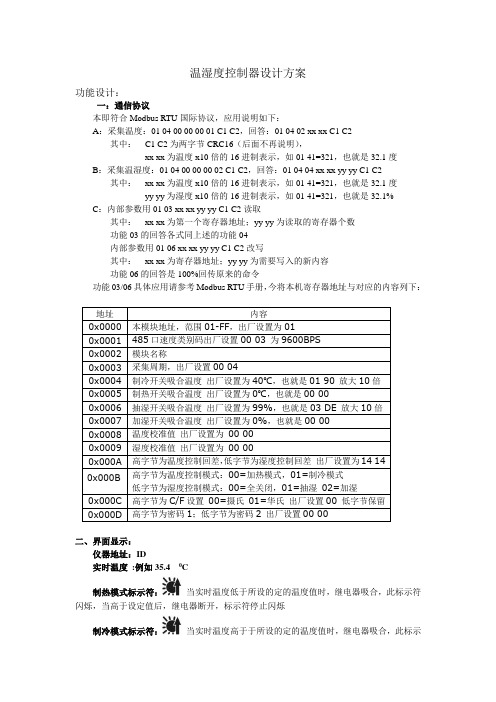
温湿度控制器设计方案功能设计:一:通信协议本即符合Modbus RTU国际协议,应用说明如下:A:采集温度:01 04 00 00 00 01 C1 C2,回答:01 04 02 xx xx C1 C2其中:C1 C2为两字节CRC16(后面不再说明),xx xx为温度x10倍的16进制表示,如01 41=321,也就是32.1度B:采集温湿度:01 04 00 00 00 02 C1 C2,回答:01 04 04 xx xx yy yy C1 C2 其中:xx xx为温度x10倍的16进制表示,如01 41=321,也就是32.1度yy yy为湿度x10倍的16进制表示,如01 41=321,也就是32.1% C:内部参数用01 03 xx xx yy yy C1 C2读取其中:xx xx为第一个寄存器地址;yy yy为读取的寄存器个数功能03的回答各式同上述的功能04内部参数用01 06 xx xx yy yy C1 C2改写其中:xx xx为寄存器地址;yy yy为需要写入的新内容功能06的回答是100%回传原来的命令功能03/06具体应用请参考Modbus RTU手册,今将本机寄存器地址与对应的内容列下:地址内容0x0000 本模块地址,范围01-FF,出厂设置为010x0001 485口速度类别码出厂设置00 03 为9600BPS0x0002 模块名称0x0003 采集周期,出厂设置00 040x0004 制冷开关吸合温度出厂设置为40℃,也就是01 90 放大10倍0x0005 制热开关吸合温度出厂设置为0℃,也就是00 000x0006 抽湿开关吸合温度出厂设置为99%,也就是03 DE 放大10倍0x0007 加湿开关吸合温度出厂设置为0%,也就是00 000x0008 温度校准值出厂设置为00 000x0009 湿度校准值出厂设置为00 000x000A 高字节为温度控制回差,低字节为湿度控制回差出厂设置为14 140x000B 高字节为温度控制模式:00=加热模式,01=制冷模式低字节为湿度控制模式:00=全关闭,01=抽湿02=加湿0x000C 高字节为C/F设置00=摄氏01=华氏出厂设置00 低字节保留0x000D 高字节为密码1;低字节为密码2 出厂设置00 00二、界面显示:仪器地址:ID实时温度:例如35.4 0C制热模式标示符:当实时温度低于所设的定的温度值时,继电器吸合,此标示符闪烁,当高于设定值后,继电器断开,标示符停止闪烁制冷模式标示符:当实时温度高于于所设的定的温度值时,继电器吸合,此标示符闪烁,当低于设定值后,继电器断开,标示符停止闪烁实时湿度:例如:53%加湿标示符:当且只有在制冷模式下,湿度控制才起作用;当实时湿度低于设定的湿度值后,湿度继电器吸合此标示符闪烁,当实时湿度高于设定值后湿度继电器断开,此标示符停止闪烁三:拨动开关的使用:产品顶部配有设置开关一只,具有左拨,右拨,下按三个控制位A:正常显示下,下按开关,C闪动进入C/F选择与设置,左右拨动选择C或F,下按开关,C或F停止闪动。
安科瑞电气股份有限公司 ATE 系列无线温度传感器 322 安装指南 V1.7说明书

安科瑞电气股份有限公司ATE series Wireless Temperature Sensor322Installation Instruction V1.7Acrel Co.,Ltd.Sales manager :Tim MaTel/whatsapp/wechat :86 187******** E-mail :******************.cn Website: www.acrel.gr1Installation Guide1.1Product IntroductionATE series wireless temperature measuring sensor has been developed in compliance with Specification for Wireless Temperature Measuring equipment,NB/T42086-2016.It is suitable for3-35kV indoor switchgears,including built-in switchgears,handcart switchgears,fixed switchgears and loop-net switchgears.It is also suitable for0.4kV low-voltage switchgears such as fixed switchgears and drawer switchgears.The wireless temperature sensors can be installed at any heating point in switchgears,the device utilizes the wireless data transmission technology for real-time transmission of monitored temperature data.In addition,it can be transmitted to display device or remote intelligent monitoring system.1.2Type Introduction1.3Technical Features1.4Product InstallationThere are several types of wireless temperature sensors and mounting methods correspondingly,i.e.Magnetic ,bolted ,belt and alloy chip fixing.1.4.1ShapeSizePower source BatteryInstallation Magnetic /bolted /BeltRange of temperature-50℃~+125℃Precision ±1℃Application Joints in high or low voltage switchgearsBattery life ≥5years 400Passive wirelesstemperature sensorWireless frequency 470MHz Communication distance 150m in open areaSampling frequency15s Transmission frequency15sPower source CT-powered,starting current≥5AInstallation alloy chip fixing Sensor probe alloy bottom Range of temperature-50℃~125℃Precision ±1℃Application Joints in high or low voltage switchgearsATE100P/200P Outdoor wireless temperature sensorWireless frequency 470MHz Communication distance 150m in open areaSampling frequency25s Transmitting frequency25s-5min Power source Battery Installation bolted /Belt Range of temperature-50℃~+150℃Precision ±0.5℃Application V oltage switchgearsBattery life ≥5years Protection levelIP68ATE100MATE100/ATE100PATE200/ATE200PATE400 1.4.2Label Instructions1.4.2.1ATE sensor with ASD/ARTM-Pn deviceASD320ARTM-PnATE400 ATE100M ATE200ATE100ATE100PATE200PIf the sensor is ATE100M/ATE100/ATE200/ATE400/ATE100P/ATE200P,the number behind“组号:”should be same as number underlined in“*51809190240001*”,the sequence of installation is base on the label,“编码:1A”is first one on the phase A,“编码:1B”is first one on the phase B,and so on.Notice:wireless temperature sensors and display device in the package have been matched before delivery.Do not use them with other display device or other wireless temperature sensors together.Please installing them with label on the sensor.1.4.2.2ATE sensor with ATC600/ATC450-C coordinatorATC600ATC450-CATE400ATE100ATE100MATE200ATE200PATE100P According to the above pictures,If the sensor is ATE100M/100/200/400/100P/200P,the group number of ATE must be same with the group number of ATC450-C/ATC600and the installation order is base on the label.The code of each sensor is used to distingguish each sensor from same group.“code:001”is recommended to be installed on the first temperature measuring point of the first cabinet,and then installed other sensors in this order.In case of any special situation,please contact the relevant engineers for communication.1.4.3Installation Method1.4.3.1ATE100M Installation MethodThe magnetic wireless sensor ATE100M is suitable for iron electrical nodes or equipment surfaces.Structure introduction of ATE100M:1——The core of wireless temperature sensor ATE100M 2——Thermo-sensitive part 3——battery switch21131Adsorbed directly at the iron temperature measuring point,open the battery switch before installation,the power indicator flashes twice.The installation examples see images below.1.4.3.2ATE100Installation MethodThe bolted type wireless sensor ATE100is suitable for use at joints between cable and bus bar andjoints between cable and disconnector.ATE100structure introduction:1——The core of wireless temperature sensor ATE1002——Thermo-sensitive part 3——batteryswitch3121Remove the screw from the joints,and fixing the sensor on the position with the hole on the alloy baseplate,then tighten the screw,open the battery switch before installation,the power indicator flashes twice.The installation examples see imagesbelow.1.4.3.3ATE200Installation MethodThe strap-secured type called ATE200is suitable for use at moving contacts and fixed contacts of breaker,cable joints and bus bar.ATE200structure introduction:1——The core of wireless temperature sensor ATE200,temperature measuring probe is on the other side2——strap and hasp 3——battery switch1312Fixing the body of sensor on the position,then strapping it on the bus bar or breaker contact and frapping it through the hole on the strap,fixing the strap by hasp.Clipping the strap if it is too long when finished,if it is too short,contacting us for strap parts before installation.Open the battery switch before installation,the power indicator flashes twice.The installation examples see imagesbelow.1.4.3.4ATE400Installation MethodThe mini type called ATE400is suitable for using at moving contacts,bus bars,cables and joints between bus bar and cable.Mini type passive temperature sensor structure introduction:1——The core of wireless temperature sensor ATE4002——alloy bottom,touched with temperature probe 3——metal hasp,for fixing alloy chip 4——alloy chip,for CT-powered5——silicone gasket,used to support the alloy chip 6——alloy chip hole,used to install the alloychip21513141Firstly,take2pieces of alloy chips through the mounting hole of metal hasp,meanwhile fold the alloy chips and fix the metal hasp in the middle of alloy chips.Secondly,take the folded alloy chips through one silicone gasket,the core of ATE400and another silicone gasket in turn.Thirdly,circle the whole alloy chips around the mounting position and tension the alloy chips,then tighten the screw on the metal hasp.Finally, subtract the excess alloy chips.The complete installation process is shown in Figures1to4.The wireless temperature sensor called ATE400installation examples,see images below.1.4.4Wireless Temperature CoordinatorThe wireless temperature coordinator connected with ATE series wireless temperature sensor ATC450-C which can be mounted on rail(DIN35mm)or bolted directly.The wireless temperature coordinator connected with ATE series wireless temperature sensor ATC600which can be mounted on rail(DIN35mm).安科瑞电气股份有限公司AppendixPrecautions1)Please select the most suitable wireless temperature measurement product according to the installation location and requirements.2)For the installation of all sensors,please strictly follow the instructions in the manual.If there is insufficient accessories due to installation errors,the customer shall bear the responsibility.3)Before placing an order for wireless temperature measurement products,you need to have a detailed configuration plan,and fill in the Acrel Wireless Temperature Measurement Confirmation Form!Then submit the plan and form to the back office.Jiangsu Acrel Electrical MFG Co.,Ltd.(Production Base)Address:No31HongtuRd,NanzhaJiangyinJiangsuWebsite: www.acrel.grSales manager:Tim MaTel/whatsapp/wechat:8618761599716E-mail:******************.cn11。
温度控制器安装和使用说明书
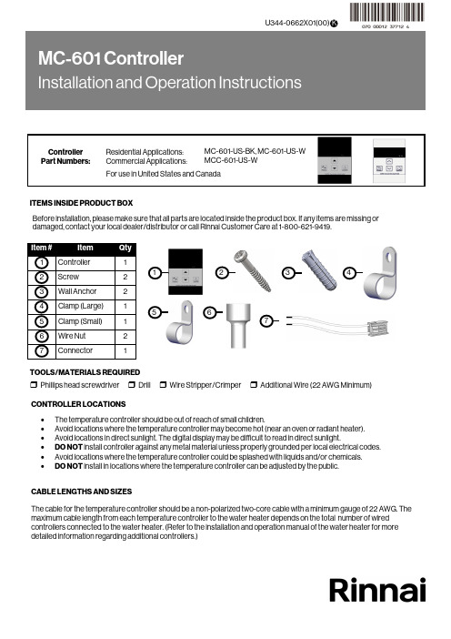
CONTROLLER LOCATIONS ∙ The temperature controller should be out of reach of small children.∙ Avoid locations where the temperature controller may become hot (near an oven or radiant heater). ∙ Avoid locations in direct sunlight. The digital display may be difficult to read in direct sunlight.∙ DO NOT install controller against any metal material unless properly grounded per local electrical codes. ∙ Avoid locations where the temperature controller could be splashed with liquids and/or chemicals. ∙DO NOT install in locations where the temperature controller can be adjusted by the public.CABLE LENGTHS AND SIZESThe cable for the temperature controller should be a non-polarized two-core cable with a minimum gauge of 22 AWG. The maximum cable length from each temperature controller to the water heater depends on the total number of wired controllers connected to the water heater. (Refer to the installation and operation manual of the water heater for moredetailed information regarding additional controllers.)Before installation, please make sure that all parts are located inside the product box. If any items are missing or damaged, contact your local dealer/distributor or call Rinnai Customer Care at 1-800-621-9419.123ITEMS INSIDE PRODUCT BOXTOOLS/MATERIALS REQUIRED456❒ Phillips head screwdriver ❒ Drill ❒ Wire Stripper/Crimper ❒ Additional Wire (22 AWG Minimum)71.Make 3 holes in the wall as shown below. (Reference template on last page.)2. Remove the face plate from the temperature controller using a screwdriver.When performing the steps in this section, you must follow the wiring guidelines established by the National Disconnect power to the water heater. Do not attempt to connect the temperature controller(s) with the power on.WARNING3. After disconnecting power to the water heater, connect the field-supplied wire to the stripped wire ends of the con-troller . Follow the wiring guidelines established by the National Electrical Code (NEC).4. Using the provided screws and wall anchors, mount the controller to the wall.5. Remove the protective film from the controller.Number of Controllers Maximum Cable Length for Each Controller toWater Heater1 328 ft. (100 m)2 164 ft. (50 m)3 or 465 ft. (20 m)Controllers wired in seriesControllers wired in parallelControllers canonly be wired in parallel; theycannot be wired inseries.FilmCover Plates3.31 i n . (84m m )1.65 i n . (42m m )1.Remove the front panel of the water heater.2. Locate the terminals for control in the water heater.3. Thread the cable through the base of the water heater4. Connect controller wires to the terminals for control.For additional information regarding installation and/or operation of the temperature controller, please refer to the Installation and Operation Manual of the water heater. 1.If the water heater is off, press the “On/Off” button to turn on.2. The “Priority” button enables a controller if multiple controllers are being used. If the “Priority” light is off, then press the“Priority” button on the temperature controller. The green “Priority” light will glow indicating that this controller iscontrolling the temperature and that the water heater is ready to supply hot water. The priority can only be changed while no hot water is running. 3. Press the (Up) or (Down) buttons to obtain the desired temperature setting. All hot water sources are able toprovide water at this temperature setting until it is changed again at this or another temperature controller. 4. To operate the water heater, open any hot water fixture. The water heater will then activate and the water heater “In Use”indicator will illuminate on the controller show that the water heater is providing hot water. For further information on controller operation, refer to the installation and operation manual of the water heater.Enables controller when multiplecontrollers are usedDisplayDecreases hot water temperatureIncreases hot water temperatureTurns the water heater on or off“In Use” IndicatorInstalling Four Controllers 1.If 4 MC-601’s are installed, press the “Priority ” and “On/Off ” buttons on the fourth controller at the same time until a beep sounds. (See above)2. Check that the displays on all four controllers are lit and displaying the temperature setting when switched on. If any ofthe controllers displays two dashes then repeat step 1. Note: If a controller is replaced, repeat these steps for the replacement controller.In applications where a Rinnai Control-R™ module is installed in place of a 4th controller and there is: ∙ Option 1 in Rinnai Control-R™ mobile app - “No Recirculation” - Perform Step 1 above.∙ Option 2 in Rinnai Control-R™ mobile app - “Recirculation” - Step 1 above is not necessary.HOTBURNSecuring Screw Securing Screw Wiring Hole Overall Controller Dimension: ∙ W: 3.54 in. ∙ H: 4.72 in. ∙D: 0.70 in.Ø.20Ø.50Ø.20100000570(02)9/2022。
温湿度记录仪操作规程(3篇)

第1篇一、概述温湿度记录仪是一种用于监测和记录环境温湿度的电子设备,广泛应用于实验室、冷库、仓储、农业等领域。
为确保记录仪的正常使用和数据准确性,特制定本操作规程。
二、适用范围本规程适用于所有型号的温湿度记录仪,包括但不限于DLM11C(蓝牙版)等。
三、操作步骤1. 开机与设置- 短按开机键,启动记录仪。
- 观察显示屏,确保显示信号、定位、云图标、电量和当前环境温度,确认设备开机正常。
- 根据需要,设置记录仪的报警参数,如温度上限、下限,湿度上限、下限等。
2. 记录数据- 长按启停键,显示屏左下角出现三角图标,开始记录打印数据。
- 温度超限时,设备会发出“滴滴滴”的声音,指示灯为橙色闪烁,请注意查看并处理。
- 需要停止记录时,长按启停键,显示屏左下角三角图标变为正方形图标,停止记录打印数据。
3. 轮询查看- 短按打印键进行轮询查看,依次显示当前温度、温度最大值、温度最小值、当前湿度、湿度最大值、湿度最小值、剩余使用天数、当前版本号等信息。
4. 蓝牙打印- 长按打印机开机键,打印机显示为红色指示灯。
- 长按记录仪打印键,电量左边出现打印图标。
- 等待打印机从红色指示灯自动转为蓝色指示灯。
- 短按记录仪打印键,打印机图标闪烁,开始打印。
5. 关机- 同时长按打印键与开机键3秒以上,显示屏关闭,完成关机操作。
四、注意事项1. 设备处于打印状态下无法记录数据,需退出打印模式后才能记录数据。
2. 设备开机后需要等待设备搜索信号,连接平台,显示屏上出现云图标后,再进行发运操作。
3. 设备停止发运后,如需重新开始记录,请重新开启记录仪并设置相关参数。
4. 定期检查记录仪的电量,确保设备正常工作。
5. 避免将记录仪置于高温、潮湿或阳光直射的环境中,以免影响设备性能。
6. 使用完毕后,请妥善保管记录仪,避免损坏。
五、维护与保养1. 定期清洁记录仪,保持设备表面干净。
2. 定期检查记录仪的传感器,确保其正常工作。
3. 如发现设备故障,请及时联系专业人员进行维修。
控制器的使用方法说明书
控制器的使用方法说明书一、概述本说明书旨在向用户介绍控制器的使用方法和注意事项,以确保用户能够正确且高效地使用控制器。
以下将详细描述控制器的组装、连接、操作等方面的内容。
二、控制器的组装1. 将控制器的主体组件与所需的外部模块进行连接,并确保连接牢固。
2. 在组装过程中,注意检查控制器及其连接线是否有损坏或缺失,如有,则及时更换或进行修复。
三、控制器的连接1. 将合适的电源线插入控制器的电源接口,并将另一端连接到可靠的电源插座。
2. 将控制器的信号线与被控制设备进行连接,确保连接正确无误,避免因接错线而造成故障。
3. 若需要将控制器与其他外设设备进行连接,则按照设备说明书的要求进行连接。
四、控制器的操作1. 开机和关机a. 建议按下控制器上的电源开关按钮,确保正确安全地开启和关闭控制器。
b. 在开机或关机过程中,注意观察控制器的指示灯状态,确保操作正确。
2. 功能操作a. 根据所使用的控制器类型和功能,按下相应按钮或触摸屏等进行操作。
b. 在操作过程中,注意遵循操作指南和操作顺序,确保正确使用各项功能。
c. 如遇到功能设置或参数调整等问题,可参考控制器的用户手册或在线帮助功能。
五、控制器的注意事项1. 防潮防尘a. 因控制器内部电子元件对潮湿和尘埃敏感,请确保控制器安装在干燥通风的环境中,并避免灰尘直接进入控制器内部。
b. 在擦拭控制器时,使用干燥软布进行清洁,避免使用过湿或化学溶液进行清洗。
2. 温度控制a. 控制器的工作温度范围通常在指定的范围内,超出范围可能会导致设备损坏或异常。
b. 在冷却中设备中使用控制器时,应确保控制器处于适宜的温度环境中。
3. 安全用电a. 当连接控制器至电源时,确保电源线末端未插入电源插座或电源开启前,确保所有的电气连接良好。
b. 在使用控制器时,严禁将导线或插头等金属物体接触控制器内部的接口,以避免触电或电路故障的发生。
六、维护和保养1. 定期检查控制器的连接线是否牢固,如有发现磨损或松动的情况应立即进行维修或更换。
恒温湿度控制器用户指南说明书

Book 1 4
PC 111
Catalog No. 565-163
Printed in U.S.A.
Form 50HS,HX-1SO
Pg 1
8-94
Replaces: 50HS-1SO
Tab 5a 5a
WELCOME TO EFFICIENT YEAR-ROUND COMFORT
Congratulations on your excellent choice and sound investment in home comfort!
Improper installation, adjustment, alteration, service, maintenance, or use can cause explosion, fire, electrical shock, or other conditions which may cause personal injury or property damage. Refer to this manual. For assistance or additional information consult a qualified installer, service agency, distributor, or branch. The qualified installer or agency must use only factory-authorized kits or accessories when modifying this product.
OPERATING YOUR HEAT PUMP
The operation of your heat pump system is controlled by the indoor thermostat. You simply adjust the thermostat and it maintains the indoor temperature at the level you select. Most thermostats for heat pump systems include temperature control selector, FAN switch, and SYSTEM switch. EMERGENCY HEAT control is usually provided with the SYSTEM switch.
温湿度可编程控制器操作手册
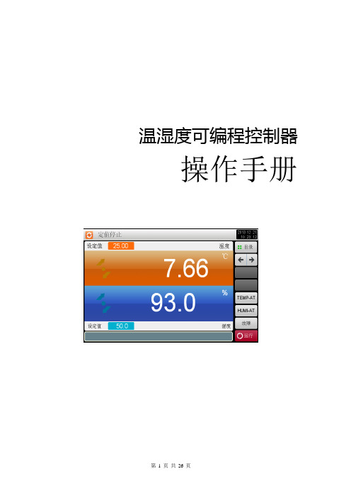
温湿度可编程控制器操作手册目录1.前言 (3)2.概要 (3)2.1 SYSTEMP构成图 (3)2.2 电气连接示意图 (4)3. 主画面介绍 (5)3.1 主画面 (5)3.2 定值(FIX)运行 (6)3.3程序(PROGRAM)运行 (8)3.4故障显示画面 (10)4. 运行相关操作设定 (11)5. 程序组设定 (11)5.1 程序组模式设定 (12)5.2程序循环设定 (14)5.3 等待动作 (15)5.4 时间信号操作 (15)6. 曲线显示 (16)7. 画面显示设定 (17)8. 预约设定 (17)9.通信故障 (18)10.系统设置画面 (19)10.1 报警设置画面 (20)10.2 I输入设定画面 (21)10.3 PID设定画面 (21)10.4 T设定画面 (22)10.5 IS设置画面 (22)10.6 DI设定画面 (23)10.7 继电器设定画面 (23)10.8 初始化设置画面 (26)1.前言本操作说明书针对日常操作之参数祥加说明。
安全注意事项记载了有关安全的重要内容,请务必遵守。
1、本控制器可以正常工作于一般场合,如果担心本控制器的故障或异常会造成重大事故或损坏其它设备时,请另外设置避免事故的紧急停止电路和保护回路,以防止事故的发生。
2、为避免发生控制器故障,请提供额定电压范围内的电源。
3、为了防止触电或产生误动作和故障,在安装和连线结束之前,请不要接通电源。
4、本产品为非防爆产品,请不要在有可燃或爆炸性气体的环境中使用。
5、绝对不能擅自拆卸、加工、改造或修理本控制器,否则会产生异常动作、触电或火灾的危险。
6、接通电源后,请不要触摸电源端子,否则会有触电危险或产生误动作。
7、关闭电源后,才可进行接线的拆卸,否则会有触电危险或产生误操作。
8、连接测温电阻(PT100)输入时,要使用3条阻值相等且小于10Ω的导线,否则会造成显示误差或动作异常。
9、控制器在运转中,进行修改设定、信号输出、启动、停止等操作之前,应充分地考虑安全性,错误的操作会使工作设备损害或发生故障。
温度控制器操作说明书

温度控制器操作说明书一、产品概述温度控制器是一种用于自动调控设备温度的智能电子仪器。
通过采集温度数据,并根据预设的温度范围进行控制,实现精确的温度控制和调节。
本操作说明书将为您详细介绍温度控制器的使用方法和注意事项。
二、产品外观和组成1. 外观描述温度控制器外观小巧精致,采用黑色塑料材质。
正面配备液晶显示屏和按键控制区域,底部有插孔用于连接传感器。
整体设计简洁大方,符合人体工学原理,易于操作。
2. 组成部件温度控制器由以下主要部件组成:(1) 显示屏:采用液晶技术,以数字方式实时显示当前温度和设定温度。
(2) 控制按键:包括上、下、确定等按键,用于设置和调节温度参数。
(3) 传感器插孔:用于插入温度传感器连接线,将温度数据输入到控制器中。
三、使用方法1. 上电及初始化将温度控制器插头与电源插座连接,按下控制器背面的电源开关,控制器即可供电并初始化显示正常。
2. 温度控制设置(1) 按下控制器上的“设定”按钮,进入温度设定模式。
(2) 使用上下按键选择您需要的温度设定值,按下“确定”按钮确认设定。
3. 温度读数显示(1) 控制器将实时显示当前温度数值,您可以通过温度单位按钮切换摄氏度或华氏度显示。
(2) 当温度达到设定值时,控制器将发出声音提示,并停止加热或制冷操作。
4. 温度报警功能(1) 温度控制器具备温度报警功能,当温度超出设定范围时,控制器将发出报警声音,并在显示屏上闪烁提示。
(2) 若出现温度超出设定范围的情况,请立即检查设备故障并采取相应措施以避免损坏。
5. 温度控制模式切换温度控制器支持手动模式和自动模式的切换。
您可以根据需要选择手动模式或自动模式进行温度控制。
(1) 手动模式:您可以通过手动设定的方式控制温度升高或降低。
(2) 自动模式:温度控制器将根据您设定的温度范围自动进行温度控制,保持设备处于所需的温度状态。
四、注意事项1. 使用环境请确保在干燥、通风良好的环境中使用温度控制器,并避免阳光直射、潮湿或过于高温的环境。
温湿度控制仪表说明书

温湿度控制仪使用说明书温湿度控制仪,具有温湿度同时数字显示,控制值分别显示、定时打印记录等功能,仪表同时具有电压监测功能,缺水保护功能(内部有水位传感器输入接口,只要配接水位传感器,就可以适用需要缺水指示或报警的场合),内置循环定时器,使控制更加灵活,设备配上该仪表,将使其具有很高的自动控制功能。
一、主要技术指标1.1控温范围:0℃----50℃1.2控温灵敏度:±0.5℃控湿灵敏度:±2%RH1.3测温准确度:±0.3℃测湿准确度:5% ~ 7%RH1.4温、湿度控制值及上、下限:可以由用户根据需要设定。
1.5打印记录定时范围:0---999秒可设定。
1.6循环定时器定时范围:工作时间0---9.9分钟、停止时间0---9.9分钟。
1.7上位机通信定时范围:0---9.9分钟。
1.8上限工作延时设定范围:0---9.9分钟。
1.9控温输出功率:电压220V±10%AC、电流5A;控湿输出功率:电流3A;风机输出功率:电流1A。
1.10仪表工作环境条件:0℃---±45℃,相对湿度不大于85%。
1.11仪表工作电压:220V±10%;仪表功耗:<6瓦。
1.12温、湿度传感器:(智能型)1.13仪表安装开空尺寸:1 50×75(mm)。
1.14仪表外形尺寸:160×80×170(mm)。
1.15仪表重量:<1kg1.16打印机:(可扩展)二、工作原理本仪表将干、湿温传感器的等效信号转成相应的数字信号,再由微处理器进行处理后显示和智能控制。
(用户如需定时打印温度和湿度,仪表可扩展时钟和打印机接口。
扩展后,仪表能根据设定的打印时间,定时打印“年、月、日、时、分”和当时的温度、湿度。
使用时应把仪表后面板标有打印机接口(R、T)字样的两个接线端与打印机后面板对应的接线端相连,并把220V交流电源接到打印机后面板标有相,中的接线端。
温湿度变送器使用说明书

明书一.概述传感,变送一体化设计,适用于暖通级室内环境的温湿度测量。
二.供 量 准 确外 三.不可逆损坏)V+ (电源正或两线制供电正) T (温度输出) H (湿度输出)图例中A ,B 为显示仪表,执行器或采集卡,A 路对应湿度输出,B 路对应温度输出。
两线制4mA ~20mA 电流远传(NWSF-1AT)可以独立供电(温度和湿度两路信号彼此隔离)1、 变送器应尽量垂直放置,安装时,保证传感器在变送器的下方(变送器上的字体为正方向)。
2、 安装高度为人体坐高或主要要求测量的环境区域。
安装注意事项:1、打开上盖时,注意避免碰到DT-S 、HH 位置 所焊接的传感器,以免造成损坏。
4~20mA明书2、避免在易于传热且会直接造成与待测区域产生温差的地带安装,否则会造成温湿度测量不准确。
3、安装在环境稳定的区域,避免直接光照,远离窗口及空调、暖气等设备,避免直对窗口、房门。
4、尽量远离大功率干扰设备,以免造成测量的不准确,如变频器、电机等。
五.使用1、仔细检查,确保接线正确后,接通DC 24V电源,用万用表测量时就会测量出对应的电流或电压值。
2、如想拆卸变送器,用必须先断开电源,然后进行拆卸。
3、此变送器为室内型,变送器内部避免有水进入,以免造成损坏。
六.注意事项1、使用前请认真阅读本说明书,确保接线正确。
任何错误接线均有可能对变送器造成不可逆损坏。
2、避免在易于传热且会直接造成与待测区域产生温差的地带安装,否则会造成温湿度测量不准确。
3、防止化学试剂、油、粉尘等直接侵害传感器,勿在结露、极限温度环境下长期使用。
请勿进行冷、热冲击。
七、保养1、变送器长时间使用会产生偏移,为保证测量准确度,最好每年校准一次。
八、运输、存储1、变送器尽量避免震动,轻拿轻放。
2、长时间存储条件:10℃~40℃;20%RH~80%RH。
九、开箱检查1、打开包装后,检查变送器是否完好。
2、变送器一台,说明书一份,合格证一份。
十、故障分析与排除1、如变送器输出为0,或输出值不再量程之内,请检查接线是否正确,是否牢固。
