安捷伦脉冲发生器81104A使用说明
安捷伦气质联用仪操作规程

*创作编号:BG7531400019813488897SX*创作者:别如克*Agilent 7890 A/ 5975C气相色谱质谱联用仪操作规程1. 开机1)打开载气钢瓶控制阀,设置分压阀压力至0.5Mpa 。
2) 打开计算机,登录进入Windows XP系统,初次开机时使用5975C的小键盘LCP输入IP地址和子网掩码,并使用新地址重起,否则安装并运行Bootp Service 。
3)依次打开7890AGC、5975MSD电源(若MSD真空腔内已无负压则应在打开MSD电源的同时用手向右侧推真空腔的侧板直至侧面板被紧固地吸牢),等待仪器自检完毕。
4)桌面双击GC-MS图标,进入MSD化学工作站5)在上图仪器控制界面下,单击视图菜单,选择调谐及真空控制进入调谐与真空控制界面, 在真空菜单中选择真空状态,观察真空泵运行状态,此仪器真空泵配置为分子涡轮泵,状态显示涡轮泵转速涡轮泵转速应很快达到100 %,否则,说明系统有漏气,应检查侧板是否压正、放空阀是否拧紧、柱子是否接好。
2. 调谐调谐应在仪器至少开机2个小时后方可进行,若仪器长时间未开机为得到好的调谐结果将时间延长至4小时。
1)首先确认打印机已连好并处于联机状态。
2) 在操作系统桌面双击GC-MS图标进入工作站系统。
3)在上图仪器控制界面下,单击视图菜单,选择调谐及真空控制进入调谐与真空控制界面。
4) 单击调谐菜单,选择自动调谐调谐MSD,进行自动调谐,调谐结果自动打印。
5) 如果要手动保存或另存调谐参数,将调谐文件保存到atune.u中。
6) 然后点击视图然后选择仪器控制返回到仪器控制界面。
注意:自动调谐文件名为ATUNE.U标准谱图调谐文件名为STUNE.U其余调谐方式有各自的文件名.3. 样品测定3.1 方法建立1)7890A配置编辑点击仪器菜单,选择编辑GC配置进入画面。
在连接画面下,输入GC Name:GC 7890A;可在Notes处输入7890A 的配置,写7890A GC with 5975C MSD。
脉冲调制信号相位噪声测试
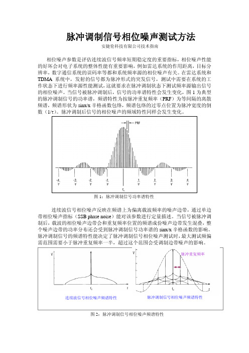
脉冲调制信号相位噪声测试方法安捷伦科技有限公司技术指南相位噪声参数是评估连续波信号频率短期稳定度的重要指标,相位噪声性能的好坏会对电子系统的整体性能有重要影响,例如雷达系统的作用距离,目标分辨率,数字通信系统的误码率等都和系统频率源的相位噪声有关。
在雷达系统和TDMA系统中,发射的信号都为脉冲形式的突发信号,测试中需要在系统的工作状态下进行频率源性能测试,这就要求在脉冲调制状态下测试频率源输出信号的相位噪声。
当信号被脉冲调制后,信号的功率谱特性会发生变化,图1为典型的脉冲调制信号的功率谱,频谱特性为按脉冲重复频率(PRF)为等间隔的离散频谱,频谱形状为sinx/x辛格函数包络,频谱包络的过零点位置为脉冲宽度的倒数(1/τ)。
脉冲调制后信号的相位噪声的频域特性同样会发生变化。
图1:脉冲调制信号功率谱特性连续波信号相位噪声反映在频谱上为偏离载波频率的噪声边带,通过单边带相位噪声指标(SSB phase noise)能对该参数进行定量描述。
当信号被脉冲调制后,载波的相位噪声边带会和重复频率位置的频谱成份噪声边带发生混叠,整个噪声边带的功率分布还会受到脉冲调制信号功率谱的sinx/x辛格函数的影响。
脉冲调制信号的频谱特性能决定了脉冲调制信号相位噪声测试时,最大测试频偏需范围需要小于脉冲重复频率一半,超过这个范围会受调制边带噪声的影响。
脉冲重复频率连续波信号相位噪声频谱特性脉冲调制信号相位噪声频谱特性图2:脉冲调制信号相位噪声频谱特性连续波信号相位噪声时域特性脉冲调制信号相位噪声时域特性图3:脉冲调制信号相位噪声的时域特性相对连续波形式点频信号相位噪声测试,脉冲调制形式的信号相位噪声测试需要测试仪表具备相应的能力来完成测试,针对脉冲调制信号相位噪声的测试要求,工程上可以采用鉴相法和频谱分析仪测试方法来测试脉冲调制信号的相位噪声。
这两种方法测试原理不同,可以适应不同类型和脉冲参数的被测试频率源的测试要求。
表格1给出这两种脉冲调制信号相位噪声测试方法的技术特点说明。
信号发生器的使用方法
信号发生器的使用方法
信号发生器是一种常见的测试设备,用于产生预定义的信号,以模拟或测量系统中电子设备的电路效果。
信号发生器具有多种功能,常用于各种电子测量、医疗、工业控制和气象等领域。
信号发生器具有高精度、高稳定性、多功能等特点,是电子行业经常使用的一种关键测试仪器。
使用信号发生器前,首先要了解信号发生器的机械结构,并认真阅读相关的使用说明书,以熟悉其功能和特性,以便在使用时不会出现不可预料的错误。
其次,使用信号发生器需要正确安装接线,一般需要使用高精度隔离器以保证输出信号的高精度和输出信号不会受到干扰。
此外,还需要连接相应的电源和测量设备,确保其正常工作。
第三,在使用信号发生器时,要设置正确的参数。
根据不同的任务,有时需要设置信号的频率、持续时间、幅度等参数,以便完成不同的任务。
在进行测量时,应该通过专业熟练的操作者来操作,并调整相应的参数,以便更准确地获得测量结果。
同时,还应该保持对设备的关注,检查设备是否有无故障,以保证测量数据的准确性。
最后,使用完信号发生器后,应该及时进行清洁和维护,并且定期检查设备的使用状况,以保证设备的正常工作。
总之,任何想要使用信号发生器的人都需要了解该设备的机械结构,严格按照说明书的指导进行接线,熟悉其功能并设置正确的参数,
以保证安全可靠地测量。
在使用完设备后,也要及时进行维护、清洁等工作,保证设备的正常工作。
安捷伦AgilentEB频谱分析仪使用说明简介
Agilent E4402BESA-E Series Spectrum Analyzer使用方法简介宁波之猫2009-6-17目录1简介 (4)2.面板 (5)2.1 操作区 (5)2.2 屏幕显示 (7)3.各功能区的使用 (8)3.1 Control(控制)功能区 (8)3.1.1 Frequency Channel: (8)3.1.2 Span X Scale (9)3.1.3 Amplitude Y Scale (9)3.1.4 Input/Output (10)3.1.5 View/Trace (10)3.1.6 Display (11)3.1.7 Mode (12)3.1.9 Auto Cuple (12)3.1.10 BW/Avg (12)3.1.11 Trig (13)3.1.12 Single (13)3.1.13 Sweep (13)3.1.14 Source (14)3.2 Measure(测量)功能区 (14)3.2.1 Measure (14)3.2.2 Meas Setup (15)3.2.3 Meas Control (15)3.3 System(系统)功能区 (15)3.3.1 System (15)3.3.2 Preset (15)3.3.4 Print Setup&Print (16)3.4 Marker(标记)功能区 (16)3.4.1 Marker (16)3.4.2 Peak Search (16)3.4.3 Freq Count (16)3.4.4 Marker → (16)4.测试步骤举例 (17)1简介Agilent ESA-E系列是能适应未来需要的Agilent中性能频谱分析仪解决方案。
该系列在测量速度、动态范围、精度和功率分辨能力上,都为类似价位的产品建立了性能标准。
它灵活的平台设计使研发、制造和现场服务工程师能自定义产品,以满足特定测试要求,和在需要时用新的特性升级产品。
agilent脉冲信号发生器参数

agilent脉冲信号发生器参数
安捷伦8114A脉冲信号发生器是一款高功率单通道信号源,其主要参数如下:
- 频率范围:1Hz至15MHz。
- 幅度输出:1Vpp至50Vpp(50Ω至50Ω时),2Vpp至100Vpp(1KΩ至50Ω时)。
- 输出电流:20mA至1A(50Ω至50Ω时),40mA至2A(1KΩ至50Ω时)。
- 上升时间:最快可达7ns。
- 定时分辨率:100ps。
- 控制方式:可通过GPIB编程控制,采用SCPI编程命令。
- 保护功能:为保护被测器件,可调节电压、电流和占空比限制。
- 触发方式:可利用外触发或设置门限及人工触发,产生连续脉冲串。
- 人机交互:具有清楚的图形用户界面,自动设置、帮助、存储/调用等功能,易于使用。
这些参数使安捷伦8114A脉冲信号发生器能够生成精确、可重复的脉冲波形,满足各种测试需求。
安捷伦函数信号发生器Agilent 33120A的性能与使用说明
安捷伦函数信号发生器Agilent 33120A 的性能与使用说明安捷伦函数信号发生器33120A 是数字式函数信号发生器。
其内部永久存储着正弦波、方波、三角波、噪声、锯齿波、sin(x)/x 、负锯齿波、指数上升波、指数下降波、心电波,共10种函数信号。
其中,正弦波、方波的频率范围为100μHz -15MHz ,幅值范围为100mV P-P -10V P-P 。
函数信号发生器有一个HP-IB (IEEE-488)接口和一个RS-232接口,计算机通过接口可遥控函数信号发生器,在计算机中使用HP BASIC 语言程序或C 语言程序,能产生12bit 40Msa/s 的任意波形,通过接口写入函数信号发生器,函数信号发生器有四个可存储16000点的任意波形存储器。
其具体的性能指标和基本操作方法见本节后摘录自“Agilent 33120A Function Generator User Guide ”的内容。
要知道详细的内容应阅读该仪器的“用户手册”。
⒈ 信号源显示电压与实际输出电压理想信号源的内阻应为零。
若实际信号源的内阻为零,则 信号源输出端一旦短路或负载电阻过小,信号源就会因功率过 载而损坏。
实际信号源一般都在其输出端串接一个电阻R s , 使信号源既使短路,在短时间内也不会因功率过载而损坏,由 此使信号源的保护电路有时间实现对信号源输出电路进行保护, 同时发出过载警告。
称信号源输出端串接电阻R s 为信号源内阻。
安捷伦33120A (以下简称为信号源)的内阻为50Ω。
由于有了信号源内阻R s ,如图1,信号源输出端的电压,即负载电阻R L 上的电压,是信号源的电源E s 在信号源内阻R s 和负载电阻R L 上的分压,即V o ≠E s 。
信号源内设置了两个负载电阻值,开机时默认为R LD =50Ω,通过操作可修改为R LD →∞。
在信号源开机默认为R LD =50Ω时,信号源内部的电压源输出的电压为E s ,信号源显示屏上显示的电压是s s LD s LD Display E 21E R R R V =+=(1)若实际负载不是50Ω,那么负载上实际得到的电压V o 为s s L s L o E 21E R R R V ≠+=(2)即信号源显示屏上显示的电压与负载上得到的实际电压不一样,V o ≠V Display 。
安捷伦高效液相色谱仪操作说明
安捷伦高效液相色谱仪把持说明之南宫帮珍创作一、校枪及样品处置1. 校枪仪器:两个小烧杯、分析天平、移液枪1000μL、100μL步伐:翻开分析天平预热, 一只烧杯放到称量盘上调零, 一只装入纯水.将移液枪1000μL、100μL调至950μL、50μL, 分别吸取纯水称质量, 如偏年夜或偏小, 调节移液枪直至准确到0.001g.(如枪使用过久或气密性欠好, 可以准备一个小烧杯装入纯水,每次先轻轻沾湿枪口, 甩失落水或在用卫生纸吸取口上的水, 再插上枪头使用.)注意慢吸慢放, 不要挂珠.2. 样品处置:用1.5mL离心管取0.5mL发酵液, 取出样品后, 首现在离心机上离心(13000rap/min 3min).然后将样品稀释20倍, 取950μL纯水、50μL发酵液于离心管中.混匀后在离心机上离心(13000rap/min 3min).准备自动进样瓶(瓶中放上内衬管), 取200μL待测液盖紧盖子.按顺序放到自动进样盘中.二、开机1、仪器各组件将在线脱气器、泵:四元、进样器:自动进样器(六通阀)、柱温箱、检测器:示差折光检测器开关翻开.翻开计算机,进入Windows XP 画面,并运行CAC Server法式, 翻开色谱仪各组件电源, 待显示已联上各组件的信息及各模块自检完成后, 双击Instrument 1 Online , 图标翻开工作站.化学工作站自动与1200LC通讯.流动相:将流动相(一般不主张使用偏酸、偏碱的流动相)放入溶剂瓶中, 翻开冲刷阀, 设流速为2ml/min, 单击确定 , 再依次单击泵→控制, 选中启动, 单击确定, 则系统开始冲刷, 至管路无气泡为止, 切换管路反复把持至所需管路均无气泡.在“控制”选项中选“关闭”, 关闭泵, 关闭冲刷阀.单击泵下面瓶图标, 输入溶剂的实际体积和瓶体积.每次四元泵开始前, 要翻开冲刷阀阀门以5ml/min的流速冲刷10分钟, 使脱气机与泵之间的流动相从冲刷阀流出, 以免隔夜的流动相损伤色谱柱.每次进样检测前, 要用流动相冲刷色谱柱30分钟, 到达柱温前20min流速设为0.2ml/min, 达柱温后再改为0.6ml/min.待1—1.5h检测器的基线稳定方可进行进样检测;检测结束后, 色谱柱要先用水冲刷20分钟, 然后用甲醇或乙腈冲刷至少20分钟,以延长色谱柱的使用寿命.绝对禁止偏酸、偏碱的流动相以及缓冲液在色谱柱中过夜.三、编纂分析方法新方法建立:法式菜单显示绿色, 即可进行参数设置及把持泵参数设定:设定流速、比例、运行时间、平衡时间、泵辅助设定(梯度)等.点击确定进入下一画面自动进样器参数设定:设定进样量(5μL)、抽取位置(调节针高度 3.0mm)、进样方式等.“序列”→序列参数→子目录(日期:年月日时间)“序列表”:拔出/批量输入向导→“追加”、“拔出”→“样品位置”、“开始位置”、“增量”、“拔出行数”标准进样:只能输入进样体积, 此方式无洗针功能.洗针进样:可以输入进样体积和洗瓶位置此方式针从样品瓶抽完样品后会在洗瓶中洗针.柱温箱参数设定:测按时75℃, 反冲时80℃.(在”温度”下面的方框内输入所需温度,并选中它,点击”更多>>”键,选中“与左侧相同”使柱温箱的温度左右一致, 点击“确定”进入下一界面.检测器参数设定-示差参比池冲刷:10min(校零).不需要每次都冲刷.温度设置50℃(不要设很高, 与检测器温度相立即可)选中点击确定进入下一画面方法保管单击方法另存为输入一—方法名, 如test 单击确认选择已有方法:点击【Method】, 点击【Load method】选项, 选取已存的各种把持方法.四、样品分析与收集数据将样品放于样品盘中相应位置, 所有的样品均需廓清.“序列”→“序列参数”:依照自动进样盘上的样品瓶的顺序编写参数(样品瓶位置、名称、方法).待仪器显示Ready, 基线平稳, 从【Run control】菜单中选择【Run Method】, 开始进样分析.或点击“开始”开始进样分析.数据处置:单击【View】菜单, 单击【Data analysis】选项, 进行数据分析.单击【View】菜单, 单击【Method and Run control】选项, 回到样品分析界面.数据分析方法编纂从File 菜单选择Load signal 选中您的数据文件名, 单击Ok积分:从“积分”中选择“积分”,如积分结果不理想,再从菜单中选择“积分事件”选项选择合适的斜率灵敏度、峰宽、最小峰面积、最小峰高从积分菜单中选择积分选项则数据被积分如积分结果不理想则修改相应的积分参数直到满意为止单击左边图标将积分参数存入方法五、标准曲线的绘制1.称取葡萄糖、果糖、蔗糖(恒重)各1g准确到, 稀释到1000mL容量瓶中.2.将标准溶液摇匀, 用离心管取糖标液, 准备自动进样瓶(瓶中放上内衬管), 取200μL待测液盖紧盖子.3.设置:将样品放于样品盘中相应位置, 所有的样品均需廓清.“序列”→“序列参数”:依照自动进样盘上的样品瓶的顺序编写参数(样品瓶位置、名称、方法、进样量:相应成梯度的量).用浓度和峰面积回归, 就获得了标准曲线7、关机冲刷系统:反相柱用10%的甲醇水冲刷系统30分钟, 再用100%甲醇冲刷系统20分钟, 然后关泵, 正相柱先用合适溶剂冲刷, 后用柱保管液冲刷.退收工作站, 关闭计算机.关闭10%异丙醇溶液控制阀.关闭仪器各组件关失落电源开关8、注意事项⑴、色谱柱使用前仔细阅读色谱柱附带的说明书, 注意适用范围, 如pH值范围、流动相类型等;必需使用呵护柱;色谱柱长时间不用时, 柱内应布满溶剂, 两端封死保管.⑵、流动相使用前必需过滤, 不要使用多日寄存的蒸馏水(易长菌).⑶、仪器运行时, 泵头必需用10%异丙醇水溶液虹吸冲刷, 不能干涸.⑷、注意各流动相所剩溶液的容积设定, 若设定的容积低于最低限会自动停泵.⑸、对手动进样器当使用缓冲溶液时要用水冲刷进样口同时挪动转移进样阀数次每次数毫升⑹、若使用含盐流动相, 开机时必需先用10%甲醇水溶液冲刷20分钟以上再换上含盐流动相.⑺、溶剂瓶中的沙芯过滤头容易破碎, 在更换流动相时注意呵护, 当发现过滤头变脏或长菌时, 不成用超声洗涤, 可用35%稀硝酸溶液浸泡后再洗涤.⑻、检测器的灯有使用寿命限制, 一般在正式进样分析前30min 左右开启D灯或W灯, 分析结束, 立即关灯.⑼、使用双泵时, A、B、C、D四相中, 若所用流动相中有含盐流动相, 则A、D(进液口位于混合器下方)放置含盐流动相, B、C (进液口位于混合器上方)放置不含盐流动相.9、如何防止溶剂瓶内溶剂过滤器的梗塞及其处置请严格执行溶剂过滤请勿使用多日寄存的蒸馏水及磷酸盐缓冲液如果应用许可可在溶剂中加入0.0001---0.001M的叠氮化钠.在溶剂瓶内溶剂的上方小流量连续吹氩气,以隔绝空气防止使溶剂瓶流露在直射阳光下尽量使用琥珀色的溶剂瓶盛放水溶液或磷酸盐缓冲液梗塞后的处置法方法:将过滤头从组件中取下在35%硝酸液中浸泡1h, 然后用二次蒸馏水冲刷干净.不能超生清洗.10、泵的维护⑴、流动相使用前必需脱气过滤⑵、使用缓冲盐时要加在线Seal-wash选项⑶、关机前反相色谱柱用10%的甲醇水冲刷系统20分钟, 然后用有机溶剂冲刷系统10分钟, 然后关泵.正相色谱柱用适当的溶剂冲刷.⑷、及时更换Purge Valve内的过滤芯, 当翻开Purge Valve时压力高于10bar 标明过滤芯已堵⑸、使用合适的密封圈:标准密封圈能适合于年夜大都应用.但使用正相溶剂最好使用聚四氟乙烯密封圈, 泵的压力限制最年夜压力设为200bar.⑹、使用梯度比例时的注意事项:当盐溶液与有机溶剂溶液混合时盐溶液能与有机溶剂溶液完全混溶而不会呈现沉淀.由于在比例阀的混合点重力作用使盐颗粒沉淀下来通常阀A接水相/盐溶液D接有机溶剂此法连接可有效使盐回落到盐溶液中并被溶解若倒置过来盐可能落在有机溶剂中呈现问题当使用缓冲盐溶液和有机溶剂时推荐将缓冲盐通道接在A通道上有机溶剂通道直接接在A通道的上方D通道上按期用水冲刷所有的通道以除去阀口上可能呈现的盐沉淀11、自动进样器使用注意使用自动洗针功能自动洗针功能可以把法式设置为“带有洗针的进样”,或将自动洗针功能包含在进样器法式中.当使用自动洗针功能时, 进样针在。
Agilent信号发生器使用规范

目录1. 操作面板按钮介绍 (3)2. 相关提示 (4)3. 使用准备工作 (5)4. 波形参数设置 (6)4.1 设置输出频率 (6)4.1.1 按下“Freq”软按键 (6)4.1.2 输入理想频率的数值 (7)4.1.3 选择合适的单位 (7)4.2 设置输出振幅 (7)4.2.1 按下“Ampl”软按键 (7)4.2.2 输入理想振幅的数值 (8)4.2.3 选择合适的单位 (8)4.2.4 进入数字输入模式 (9)4.2.5 选择新的单位 (9)4.3 设置直流电偏置电压 (9)4.3.1 按下“Offset”软按钮 (10)4.3.2 输入理想的偏置电压数值 (10)4.3.3 选择合适的单位 (10)4.4 设置高电平和低电平值 (11)4.4.1 按下“Ampl”按钮选择“Ampl” (11)4.4.2 再次按下这个按钮选择“Hilevel” (11)4.4.3 设置“Hilevel”值 (11)4.4.4 按下“Lolevel”并且设置这个值 (11)4.5 选择直流电压 (12)4.5.1 按下这个按钮,然后选择 DC ON 按钮 (12)4.5.2 输入一个理想电压值作为一个偏置量 (12)4.6 设置方波的占空比 (13)4.6.1 选择方波函数 (13)4.6.2 按下“Duty Cycle”按钮 (13)4.6.3 输入理想的占空比 (13)4.7 设置一个脉冲波形 (14)4.7.1 选择脉冲函数 (14)4.7.2 设定脉冲周期 (14)4.7.3 设置脉冲的脉宽 (14)4.7.4 设置斜坡时间 (14)4.8 观察一个波形的图像 (15)4.8.1 打开图像模式 (15)4.8.2 选择理想的参数 (15)4.9 选择输出终端 (16)4.9.1 按下键。
(16)4.9.2 操作菜单来设置输出终端。
(16)4.9.3 设定理想的输出终端 (16)4.10 重置函数发生器 (16)Agilent 函数发生器使用入门指南1. 操作面板按钮介绍前面板(如下图):1-------图形模式键 2-------开关键3-------调制/扫描/脉冲键 4-------状态存储菜单键5-------有效菜单键 6-------帮助菜单键7-------菜单操作键 8-------波形选择键9-------手动触发键(仅用于扫描和脉冲) 10-------输出开关键11-------旋钮 12-------方向键13-------同步连接接头 14-------输出连接接头当某一个按钮被按下时,这个按钮被点亮,如上图中8号中sine 波形按钮。
安捷伦示波器使用说明

西安XX科技股份有限公司
5.水平和垂直控制:
水平右旋钮按下,延迟将设为零,配合缩放(Zoom)键, 可以快速访问两种不同的屏幕缩放模式,进行平移和缩放。 使用垂直右旋钮更改显示屏上通道的垂直位置。每个通道 对应一个 Vertical Position(垂直位置)控制。
西安XX科技股份有限公司
6.自动或正常触发
西安XX科技股份有限公司
右旋钮:旋转调节波形的水平移动,按下可以进行微调。 Auto Scale键:自动设置 (Autoscale) 在优化存储器的同时 ,可快速显示任何模拟或数字的活动信号,并且自动以最佳的 比例、最佳的分辨率显示波形。按Auto Scale键时,示波器将快 速确定哪个通道有活动,并将打开这些通道,对其进行定标以 显示输入信号。 Touch键:关闭/开启触屏功能。 Zoom键:快速响应和最佳分辨率的特性,对于比较复杂的 波形,按下可以进行局部放大,查看细节波形。 Clear Display键:清屏功能,当载入新波形时,新波形会 与屏幕上的原波形重叠,按下可以清楚原波形,只剩下载入的 新波形。 Default Setup键:按下可以恢复系统默认设置。
西安XX科技股份有限公司
4.5 垂直控制部分(Vertical):
左旋钮:旋转调节波形振幅,按下可以进行微调。 右旋钮:调节波形的上下移动。 关于Auto、Arm‟d和Trig‟d Auto 表示示波器自动触发 Arm‟d表示示波器的触发电流已经准备好,正在等待一个触 发条件。 Trig‟d表示trigger delay,表示延迟触发。触发方式是自动或 者普通的时候,触发显示Trig‟d ,触发方式是单次,则不显示。
西安XX科技股份有限公司
4.3 触发控制部分(Trigger):
Agilent 使用说明
安捷伦电子测量仪器使用及维护建议版本. 03.08Agilent Technologies Co. SSU-----------Be Professional , Be Expert-------目录静电的危害及防护 (3)微波接头的使用及养护常识 (12)电子测量仪器及其系统的环境要求 (16)仪器硬件故障的最终确认 (21)附录一:部分种类仪器的用户检验步骤及注意事项 (23)附录二:Agilent仪器常见故障现象及可能原因分析 (27)附录三:参考资料 (29)静电的危害及防护引言.我们在确定自己的研究课题或找到解决方案时,下一步往往就是准备好完成课题或解决方案所需的软硬件手段.而测量仪器是人们必备的硬件设施.在得到仪器后,如何高效地使用仪器,或如何避免仪器的人为损坏,能够更长时间地为我们服务,就自然而然地成为我们必须关心的环节了.静电的危害那么哪些因素可以影响或威胁到仪器的正常使用呢?了解电子测量仪器或微电子的工程师所想到的第一个词,我想必定是”静电放电”(ESD).的确,静电是我们再熟悉不过的一种现象了,除了偶而轻微电击或讨厌的静电吸附外,对我们大多数人来讲,静电似乎并不是什么了不起的问题.过去,许多从事电子工业的人也并不认为静电放电是使电子元件乃至整个电子设备损坏的一个主要原因.许多人不相信静电放电的严重性,甚至怀疑是否真正存在.这也难怪,因为要判断或检查ESD(静电放电简称-Electrostatic Dischar ge)所引起的失效比较困难,有些元件受ESD损伤后往往在经过一段时间后才失效,使人们难于追踪并确定为ESD引起的损坏.而且许多电子元件可以被远低于人能感觉的静电放电所损伤或损坏.无源器件也和有源器件一样对ESD敏感,损坏程度从性能下降直至短路那样的严重损坏.目前,许多人对自己身上常常带可观的静电以至常常受静电放电电击的现象习以为常了.可是,您知道吗?当你的手触摸及门把手或水龙头的瞬间突然感受到受电击甚至听到”啪”的一声响之时,你身上的静电已高达4000至5000伏以上了.而且.在受电击之前,你并没有任何感觉.实际上,人的身体上,衣服上经常带有几百伏到几千伏的静电.只要构成通路,积累的静电就会放电.由于在极短的时间内释放出大量的能量,常常导致电路元件损坏,因为这种放电通常大大超过许多电路元件所能承受的限度.据测试,人能感觉到”麻”时,静电电压已高达3500伏以上.高于4500伏时放电能发出响声.5000伏以上放电时可以见到火花.人感觉不到3500伏以下的静电. 现代许多高速超大规模集成电路碰到仅几十伏或更低的静电就会遭到损坏。
Agilent 81100系列脉冲码型发生器说明资料

!"# % !"# 0.1% !" 99.9% 95% !"#$ ! !"#$%&
2 ns (3 ns) - 20 ns 10 ns
- 200 ns 100 ns - 2 ms 1 µs - 20 µs 10 µs - 200 µs 20 ms 100 µs - 2 ms 1 ms -
10 ms - 200 ms
!"
!"#$%& 5 ns
Agilent 81101A Agilent 81105A 50 Ω ! 50 Ω 1 kΩ 50 Ω 1 kΩ 50 Ω 1 kΩ !" 50 Ω 50 Ω 50 Ω 50 Ω 50 Ω 50 Ω 50 Ω 100 mVpp -10.0 V -20.0 V 10.0 Vpp +10.0 V +20.0 V
!"# (10/90) !"#$%
3 ns
200 ms
≤ 3 ns
ELC ≤ 2ns/1.4 ns 1 KΩ 5 ns
20/80 !" #
Vpp ≤ 1V ELC 450 ps Vpp > 1 V
≤ 600 ps 20/80 !" ≤ 900 ps
!" # 400 ps
10%
200 ps
!" 39;()*( !"#$%&'()
!
!"# !"#$% / !"# ! / ! ! !" TTL/ECL !" / !"#$% 1.32 Gbit/s
!"#$
!"#$% !
!"#$%&'( Agilent 81110A !"#$%&'
Agilent 81150A 脉冲函数任意噪声发生器 说明书
通道 2
仅确定波形
Web 界面
选择需要的波峰因数 / 概率函数 12
工作模式
四种工作模式:
● 通道间的耦合 ● 触发模式 ● 波形类型 ● 高级模式
通道 1 和通道 2 之间的耦合
两个通道版本具有两种截然不同的操作模式:
● 耦合关闭: 两个通道单独进行操作。两个通道生成基于相同时钟参考的频率, 但可以单独选择。
由于不断缩短的设计时间和不断提高的质量目标,您正在承受巨大压力, 必须越来越快地将产品推向市场。这种压力无休无止。因为差异意味着能否在 市场竞争中生存下去,所以您经常需要测试独特的功能,并进行有效的适应性 强的测试,以对测试结果充满信心。
这些挑战需要新一代的测试仪器:
● 精确地测试设备而非信号源 ● 适用于当前和未来的测试挑战 ● 具有最少布线、最低间隔损耗和许多内置功能的即插即用解决方案
● 耦合启动: 频率、触发模式、波形类型和高级模式在两个通道中完全相同。 通道 1 和通道 2 的固定延迟是相同的。
触发模式
● 连续: 连续波、猝发、扫描或调制。外部输入不用于连续模式中。 ● 外部触发: 外部输入 (上升、下降或两者) 中的每次主动跳变都会生成一个单
一波形、猝发或扫描。 ● 外部选通: 外部输入上的活动电平 (高或低) 可生成波形、猝发或扫描。总是
软件升级到 81150A
任意比特形状码型
对器件进行极限测试 — 定义您自己的比特形状
仿真效果
- 通道的电容负载 - 非对称延迟 - 交叉点偏离 - 占空比失真 - 任意波形跳变时间 - 电平噪声 - 自 / 到电气闲置状态
的延迟
通过定义跳变, 前一个 比特会影响当前比特
NRZ 模式
安捷伦函数发生器使用详解
安捷伦函数发⽣器使⽤详解如何使⽤安捷论函数信号发⽣器(上)(原载《⽆线电》杂志07年第四期,因版⾯所限,现将“如何使⽤安捷伦函数信号发⽣器”详细原稿分上、下两部分登在⽹站上供读者学习)在电⼦仿真软件MultiSIM 9的虚拟仪器⼯具条中,有三台跨国公司安捷伦仪器虚拟仪器,其中的安捷伦函数信号发⽣器由于功能多,操作⽐较复杂,在此对它的设置和使⽤⽅法作⽐较详细地介绍,以飨读者。
虚拟安捷伦函数信号发⽣器的⾯板各按钮、旋钮和输⼊、输出端⼝等被设计成和实物安捷伦函数信号发⽣器⾯板⼀模⼀样,这使我们坐在电脑前就能享受到在实验室操作⾼级仪器的愉悦,且⽆损坏仪器的担忧。
图1是电⼦仿真软件MultiSIM 9中的虚拟安捷伦函数信号发⽣器⾯板图及各按钮的功能说明,它的型号是Agilent33120A,频宽为15MHz,不仅能产⽣⼀般的正弦波、⽅波、三⾓波和锯齿波,⽽且还能产⽣按指上升或下降的波形等⼀些特殊的波形,并且还可以由8~256点描述的任意波形。
图1下⾯结合⼏个具体例⼦介绍虚拟函数信号发⽣器Agilent 33120A的⽤法:⼀、选择波形和设置幅度操作:按下“电源开关”(Power)按钮,屏幕默认显⽰正弦波幅值100.0mVpp~,见图1所⽰,且百位数“1”处于跳动状态,见⿏标箭头所指。
这时可以按“单位输⼊”的“∧”、“∨”按钮逐步调整你所需要的正弦波百位数的幅度⼤⼩(注:⾯板上“单位输⼊”的上、下、左、右箭头和键盘上的上、下、左、右箭头通⽤,操作效果⼀样。
);第⼆种⽅法是直接按键盘上的数字键,可以改变处于跳动位的数值;第三种⽅法是⽤⿏标按住“调节旋钮”作快速调整,顺时针增⼤,反之减⼩,适⽤⼤范围改变数据。
百位数据调好后,按“单位输⼊”的“<”、“>”按钮,只要其它位的数字处于跳动状态,即可对该位数字实施上述调整;同样可以按“>”使“mVpp”跳动,配合“∧”、“∨”按钮或“调节旋钮”设置正弦波幅值单位⼤⼩,但只能在100mVpp、1.000Vpp和10.00Vpp三者之间选择。
安捷伦操作

安捷伦操作1 开机1.1 打开电脑1.2 打开液相色谱各个模块的电源1.3 双击桌面“LC1260(Online)”,进入联机界面1.4 排气:1.4.1 手动旋开泵处冲洗阀(逆时针旋转约1圈)1.4.2 右键单击“Pump”图标区域,选择“Method”选项,进入泵编辑画面,设流速:5ml/min,点击“确定”;1.4.3 右键单击“Pump” 图标区域,点击“Control”选项,选中“ON”,点击“确定”,则系统开始冲洗,直到管线内(由溶剂瓶到泵入口)无气泡为止(一般为5分钟),切换通道继续冲洗,直到所有要用通道无气泡为止;1.4.4 右键单击“Pump” 图标,点击“Method”选项,设流速:0ml/min,手动旋紧冲洗阀;1.4.5 右键单击“Pump”图标,点击“Method”选项,按照方法要求选择合适比例的流动相,设流速:1.0ml/min;(不一定是1)1.4.6 同理右键单击“Column Comp”,“DAD”图标,点击“Method”选项,按照方法的要求设置温度,波长,点击“控制” 选项,“ON”打开柱温箱和检测器。
2 编辑方法2.1 点击“Method”——“Edit EntireMethod”开始编辑完整方法;2.2 选中除“Data Analysis ”外的三项,进入下一选项卡,选择“Als”(自动进样),点击“OK”,进入下一选项;2.3 选择“Method”菜单下“Method Information”选项,在“Method Comments”中加入方法的信息(如:This is for test!),选择“OK”,进入下一选项;2.4 泵参数设定:右键单击“Pump”图标,点击“Method…”选项,设置“Flow”:如1.0ml/min;“Stop Time”:如10 min (该停止时间仅为做一个样品需要的时间),按照要求选择合适比例的流动相配比,选择“OK”,进入下一选项;2.5 自动进样器参数设定:右键单击“Sampler”图标,点击“Method”选项,选择“Injection volume”,输入进样体积,选择“OK”,进入下一选项;2.6 柱温箱参数设定:右键单击“Column Comp”,点击“Method”选项,设置“Left”温度(可设置温度范围:低于室温10℃-80℃),一般“Left”和“Right”温度一致,选择“Combined”绑定即可,“Stop Time”选择“As Pump /Injector”,选择“OK”,进入下一选项;2.7 UV检测器参数设定: 右击“DAD” ,点击“Method…”选项,下方的空白处输入所需的检测波长(可根据需要选择多个波长,最多可选8个波长);“Stop Time”选择“As Pump /Injector”;“Spectrum”——“Store”选项下,根据需要选择“None”或“All(全波长扫描)”等选项,选择“OK”,进入下一选项;2.8 编辑方法完毕,从“Method”菜单中,选中“Save Method As”,输入一方法名,选择“OK”,保存方法成功。
阿吉伦技术8110A 150MHz脉冲生成器技术规范说明书
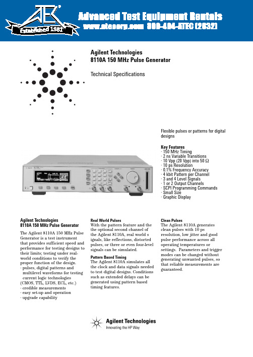
Agilent Technologies8110A 150 MHz Pulse GeneratorTechnical SpecificationsFlexible pulses or patterns for digital designsKey Features · 150 MHz Timing· 2 ns Variable Transitions · 10 Vpp (20 Vpp) into 50 Ω · 10 ps Resolution· 0.1% Frequency Accuracy · 4 kbit Pattern per Channel · 3 and 4 Level Signals · 1 or 2 Output Channels· SCPI Programming Commands · Small Size· Graphic DisplayAgilent Technologies8110A 150 MHz Pulse GeneratorThe Agilent 8110A 150 MHz Pulse Generator is a test instrumentthat provides sufficient speed and performance for testing designs to their limits; testing under real-world conditions to verify the proper function of the design.· pulses, digital patterns andmultilevel waveforms for testing current logic technologies (CMOS, TTL, LVDS, ECL, etc.)· credible measurements · easy set-up and operation · upgrade capabilityReal World PulsesWith the pattern feature and the the optional second channel of the Agilent 8110A, real world s ignals, like reflections, distorted pulses, or three or even four-level signals can be simulated.Pattern Based TimingThe Agilent 8110A simulates all the clock and data signals needed to test digital designs. Conditions such as extended delays can be generated using pattern based timing features.Clean PulsesThe Agilent 8110A generates clean pulses with 10 psresolution, low jitter and good pulse performance across all operating temperatures orsettings. Parameters and trigger modes can be changed without generating unwanted pulses, so that reliable measurements are guaranteed.19812High AccuracyExcellent accuracy over a wide temperature range guarantees repeatable measurement results.Frequency accuracy, jitter,resolution and range can be enhanced further when the Agilent 8110A is used with the internal phase locked loop (PLL) of the Agilent 81106A as pulse period source.Delay CalibrationSystematic delays caused by cables,connections and adapters can be compensated when the Agilent81107A is installed. It offers enough additional delay range to compensate for 5 m of BNC cable.External Clock or Reference Frequency 1An external synthesizer or system clock can be used as clock source at the clock input of the Agilent 8110A to achieve the frequency accuracy and required. Thisfeature is ideal for simulating digital control signalssynchronously to the clock of the microprocessor.Up to 10 channels in parallel 2Up to 4 Agilent 8110As can be slaved to a master, so that 10synchronous channels can beprogrammed independently. With the Agilent 81107A multichannel deskew installed, the propagation delay of the set-up can becompensated, and all other output channels zeroed to the reference channel.Smooth Integration into Automated Test SystemsThe Agilent 8110A can be smoothly integrated into automated test systems, ensuring:·low integration costs ·low costs of ownershipAll Digital WaveformsThe waveform and triggerflexibility of the Agilent 8110A make it a universal digitalstimulus for any automated test sys-tem.Reliable MeasurementsAccuracy is specified over the whole temperature range that exists in a test rack. Setting check and built-in diagnostics allow you to monitor the correct operation of the Agilent8110A in an automated test system.Easy Rack IntegrationThe small size of the Agilent 8110A saves valuable rack space. Rear panel connectors and rack mount kits are optional.Reduced Programming InvestmentThe local user interface eases the transition from manual toautomated measurements and from the R&D bench toautomated manufacturing test. All parameters of the Agilent 8110A are programmable via GPIB. SCPI (Standard Commands for Programmable Instruments)facilitates the standardization of test programs.Low Cost of OwnershipThe proven hardware reliability of Agilent test and measurement prod-ucts results in high uptime of test systems and low maintenance costs.The Agilent 8110A offers a 3 year standard warranty.Easy Set-up and OperationView all timing parameters for both channels at a glance. Timing and level parameters can be entered in any format, e.g. period as frequency.The alternative graphic display shows the timing relationship of all pulse parameters on both channels graphically, making setting up the pulse generator easy - no extra oscilloscope is required.Pulses and patterns can be set up quickly using the convenient cursor keys, knob and data entry keys. You can even use the Autoset Key to resolve all timing conflicts.Memory CardSettings can be storedpermanently either internally or on the memory card for duplication in another test set-up.4Pattern ModePattern length:4 kbit/channel and strobe output.Output format:RZ (return to zero), NRZ (non-return to zero), DNRZ (delayed non-return to zero). Random pattern:PRBS 2^(n-1) n = 7,8,...,12Trigger ModesContinuous:continuous pulses, double pulses, bursts (single or double pulses) or patterns. External triggered:each active input transition (rising, falling or both) generates a single or double pulse, burst or pattern.External gated:the active input level (high or low) enables pulses, double pulses, bursts or patterns. The last single/double pulse, burst or pattern is alwayscompleted.External width:the pulse shapecan be recovered. Period and width ofan external input signal is main-tained. Delay, levels and transitionscan be set.Manual:simulates an external inputsignal.Internal triggered (only with Agilent81106A):internal PLL replaces anexternal trigger source. Pulses, doublepulses, bursts or patterns can be set.Inputs and OutputsExternal inputused for trigger, gate or externalwidth.Input impedance:50 Ω /10 kΩ selec-table.Threshold:- 10 V to + 10 V.Max. input voltage:± 15 Vpp.Sensitivity:≤300 mVpp typical.Transitions:< 100 ns.Frequency:dc to 150 MHzMin. pulsewidth:3.3 ns.Strobe output and trigger outputLevel:TTL or ECL selectable.Output impedance:50 Ω typical.Strobe output: user-defined, 16 kbit pat-tern (NRZ) when in pattern mode.Max. external voltage:- 2 V/+7 V.Transition times:2 ns typical.Pattern:4096 bits NRZ in patternmode.Delay from external input to strobeoutput:in pattern mode same as fortrigger output.Trigger OutputLevel:TTL or ECL selectableOutput impedance:50 ΩtypicalTrigger pulse width:typically 50% ofperiodMaximum external voltage:-2 V/+7 VTransition times:2 ns typicalDelay from external input to triggeroutput:l8.5 ns typicalAgilent 81107A Multichannel Deskew for the Agilent 8110ACan be retrofitted without recalibration. Supports twooutput channels. Themultichannel deskew can be used for two applications:Up to 10 channels:compensates delay between external input and trigger outputs when using up to five8110As synchronously.Delay calibration:compensates for measurement system delays or pre-trigger delays of oscilloscopes. Variable range:0 ns to 28 ns Additional fixed delay:6.5 ns typical Resolution:10 ps User InterfaceOverprogramming:all parameters canbe overprogrammed(exceeding specifications) to fullyexploit the hardware limits.Setting check:warning messages indi-cate potentially conflicting parame-ters due to inaccuracy.Error messages indicateconflicting parameters.Help key:displays a context-sensitive message.Autoset key:resolves all timing con-flicts.Non-volatile memory:currentsetting is saved on power-down.Up to nine user settings and one fixeddefault setting can be stored in theinstrument.Clear memory:clears all nine user set-tings.Memory card:320 settings can bestored on a 1 MB PCMCIA card(MS-DOS ).Remote ControlOperates according to IEEEstandard 488.2, 1987 and SCPI1992.0.Function Code:SH1, AH1, T6, L4, SR1,RL1, PP0, DC1, DT1, C0.Programming times:all checks anddisplay off.GeneralOperating temperature:0°C to +55°C.Storage temperature:-40°C to +70°C.Humidity:95% r.h. up to 40°C ambi-ent temperature.EMC:conforms to EN50082-1,EN 55011, Class A.Noise emission:5.7 bel typical.Battery:Lithium CR2477-N.Safety:IEC1010, CSA1010.Power requirements:100-240 Vac, ± 10%, 50-60 Hz;100-120 Vac, ± 10%, 400 Hz.Power consumption:300 VA max.Max. dimensions (H * W * D):89 mm * 426 mm * 521 mm.Weight: 9.2 kg net, 13.8 kgshipping.Recalibration period:one year recommended.Warranty:three years standard.6Ordering Information - 8110AT he minimum order must include the 8110A mainframe and one 81103A output channel. A second output channel, the 81106A PLL/external clock or the 81107A multichannel deskew are optional. All configurations are available from the factory. Alternatively, additional modules can be ordered later and fitted by the user or an Agilent service facility.Qty per Mainframe Categorymin max Description NumberMainframe[1]1150 MHz Pulse Generator Mainframe Agilent 8110AModules1210 V/2 ns Output Channel Agilent 81103A01PLL/External Clock Agilent 81106A01Multichannel Deskew Agilent 81107AAll options are orderable with the mainframes.AccessoriesOpt UN2Rear Panel ConnectorsOpt 1CP Rack Mount and Handle Kit (5062-3975)Opt 1CN Handle Kit (5062-3988)Opt 1CM Rack Mount Kit (5062-3974)Opt 1CR Rack Slide Kit (1494-0060)Opt UFJ 1 MB SRAM Memory CardAgilent 15104A Pulse Adder/SplitterLanguage optionsOpt ABD German Localization (08110-91112)Opt ABF French Localization (08110-91212)Opt ABZ Italian Localization (08110-91312)Opt ABE Spanish Localization (08110-91412)Opt ABJ Japanese Localization (08110-91512)Opt AB0Chinese Localization (08110-91612)Additional documentation optionsOpt 0B2 Additional English Operating Manual(08110-91012)Opt 0BW Service Manual (08110-91021)08110-91031Service Documentation (Component Level)Support OptionsOpt 1BP MIL Std. 45662A Calibration with Test DataOpt W32 3 Year Customer Return Calibration CoverageOpt W34 3 Year MIL Calibration ServiceOpt W50 5 Year Customer Return Repair CoverageOpt W52 5 Year Customer Return Calibration CoverageOpt W54 5 Year MIL Calibration Service7Related Agilent Literature·Agilent Family of Pulse/PatternGenerators, brochure, p/n 5980-0489EAgilent Technologies'Test and Measurement Support, Services, and AssistanceAgilent Technologies aims to maximize the value you receive, while minimizing your risk and problems. We strive to ensure that you get the test and measurement capabilities you paid for and obtain the support you need. Our extensive support resources and services can help you choose the right Agilent products for your applications and apply them successfully. Every instrument and system we sell has a global warranty. Support is available for at least five years beyond the production life of the product.Two concepts underlay Agilent's overall support policy: "Our Promise" and "Your Advantage."Our PromiseOur Promise means your Agilent test andmeasurement equipment will meet its advertised performance and functionality. When you are choosing new equipment, we will help you with product information, including realistic performance specifications and practical recommendations from experienced testengineers. When you use Agilent equipment, we can verify that it works properly, help with product operation, and provide basic measure-ment assistance for the use of specifiedcapabilities, at no extra cost upon request. Many self-help tools are available.Your AdvantageYour Advantage means that Agilent offers a wide range of additional expert test and measurement services, which you can purchase according to your unique technical and business needs. Solve problems efficiently and gain a competitive edge by contracting with us for calibration, extra-cost upgrades, out-of-warranty repairs, and on-site education and training, as well as design, system integration, project management, and other professional services. Experienced Agilent engineers and technicians worldwide can help you maximize your productivity, optimize the return on investment of your Agilent instruments and systems, and obtain dependablemeasurement accuracy for the life of those products.By internet, phone, or fax, get assistance with all your test & measurement needs Online assistance:/find/assist Phone or Fax United States:(tel)180****4844Canada:(tel)187****4414(fax) (905) 206 4120Europe:(tel) (31 20) 547 2000Japan:(tel) (81) 426 56 7832(fax) (81) 426 56 7840Latin America:(tel) (305) 267 4245(fax) (305) 267 4286Australia:(tel) 1 800 629 485 (fax) (61 3) 9272 0749New Zealand:(tel) 0 800 738 378 (fax) 64 4 495 8950Asia Pacific:(tel) (852) 3197 7777(fax) (852) 2506 9284Product specifications and descriptions in this document subject to change without notice.Copyright © 2000 Agilent Technologies Printed in Germany 10/20005980-1212EFor more information, please visit us :/find/pulse_generator。
安捷伦信号发生器的使用 信号发生器如何做好保养

安捷伦信号发生器的使用信号发生器如何做好保养安捷伦信号发生器紧要由开关电源模块、主板、YIG调谐振荡器YTO、分频倍频幅度调制放大微波组件、微带开关滤波器组件、SDA组件、键盘显示器组件、低频扩展组件、步进衰减器、耦合器和检波器构成。
安捷伦信号发生器的使用:1、设置负斜波函数信号波形第一步:新建一个工作文档,添加安捷伦函数信号发生器、示波器、接地端。
双击安捷伦信号发生器图标,打开放大面板,点击开关。
第二步:点击“SHIFT”按钮,再单击“任意波(Arb),屏幕显示“SINC”,按键盘上的“”,屏幕显示“NEG_RAMP~”,单击“回车键”NEG表示负的,RAMP SIGNAL是斜波信号的意思。
第三步:点击“SHIFT”按钮,再两次单击“任意波(Arb)”按钮,屏幕显示“NEG_RAMP arb”第四步:设置波形的频率与幅度(Freq与Ampl)分别为2KHZ 与2Vpp,察看波形。
2、设置指数函数信号波形第一步:新建一个工作文档,添加安捷伦函数信号发生器、安捷伦示波器、接地端。
双击安捷伦信号发生器图标,打开放大面板,点击开关。
第二步:点击“SHIFT”按钮,再单击“任意波(Arb),屏幕显示“SINC”,按键盘上的“”键两次,屏幕显示“EXP_RISE~”,单击“回车键”EXP是函数的意思,FALL表示下降,RISE表示上升第三步:点击“SHIFT”按钮,再两次单击“任意波(Arb)”按钮,屏幕显示“EXP_RISE arb”,再按键盘上的“”键,则屏幕显示“EXP_FALL arb”,最后,按“ENTER”进行保存。
第四步:设置波形的频率与幅度(Freq与Ampl)分别为3KHZ 与1.5Vpp,察看波形。
下降指数函数信号波形3、设置调幅波第一步:打开信号发生器放大面板,察看信号输出为(1KHZ、100MVpp)。
第二步:点击“SHIFT”键,再按“调幅”(正弦波)按钮,在屏幕下方会显现AM字样。
安捷伦脉冲发生器81104A使用说明

华中师范大学本科生课程论文课程名称通信系统测试仪器及使用论文题目脉冲信号发生器81104A 使用简介考试时间2013年1月25日专业电子信息科学与技术年级2010级成绩评卷人姓名黄兴学号2010210839目录一、仪器简介二、注意事项三、基本原理及操作四、应用范围五、心得体会一、仪器简介脉冲码型发生器产生的所有标准脉冲,数字需要测试模式,多层次的波形目前所有的逻辑技术(如TTL,CMOS,ECL,PECL,LVDS,GTL)和其他数字化设计为330MHz。
该仪器能够提供一个可靠的和广泛的信号,使用中的应用程序比它的前辈,更安捷伦8110A。
这是由于在功能设置的增强和安捷伦8110A的规格。
毛刺和辍学自由变任何定时参数和定时校准功能的安捷伦81110A/81104A有助于得到更准确,更可靠的仪器设备。
二、注意事项在打开仪器之前,您必须将保护地球终端仪器的保护接地导体(主)电源线。
只能插在插座上的电源插头必须与保护接地的电源插座。
不要否定的保护使用没有保护接地的扩展电源线的行动导体。
接地两芯的插座的一个导体是不足够的保护。
服务指令是训练有素的服务人员。
为了避免触电危险,不要进行内部维修或调整,除非另一个人,能够提供急救和复苏,是存在的。
如果该仪器通电使用自耦变压器(电压减少),确保共同的终端被连接到接地端子的电源。
每当它是可能的接地保护减值,则必须使仪器不工作,并且确保不会被意外操作。
不要操作仪器存在易燃气体或烟雾。
任何电子仪器的操作在这样的环境构成了一定的安全隐患。
一、仪器开关:在打开仪器显示表明仪器自检运行。
这可能需要几秒钟来完成。
如果自检失败,你看到一个闪烁的E在屏幕的底部。
二、基本屏幕在这个屏幕中,您可以设置信号被选通,开始或连续的,并且是一个脉冲流,突发(几个脉冲其次停顿)或图案。
定时屏幕和电平屏幕允许您指定的时间并将所产生的信号电平参数。
在计时屏可以设置时钟频率,输出12,对信号的时间(延迟,脉冲宽度,占空比,……)。
信号发生器使用说明
5、按CH1至灯亮,输出口输出所设置的波形。
三、设置输出波形
1、打开电源,函数发生器输出默认频率为100K, 幅度1V峰-峰值的正弦波。屏幕上显示:
SINE 0.000
100.0000K 1.000 CONT OFF 0
2、按下 FUNC ,光标在SINE的首字母下,按 两个键,选择所需的波形:
第一级MENUS(菜单); 第二级COMMANDS(命令); 第三级PARAMETERS(参数)。
可以用上下键在菜单树的上下级之间跳动,用 左右键在菜单树的水平方向移动。
2、菜单简要说明
1)调制菜单(MODULATION MENU)
10条命令: 1:AM SHAPE 2:AM SOURCE 3:FM SHAPE 4:BURST CNT 5:BURST RATE 6:BURST PHAS 7:BURST SRC 8:FSK FREQ 9:FSK RATE 10:FSK SRC
第一节 任意波形信号发生器(一) TEKTRONIX AFG310型使用方法
一、设置输出频率
1、打开电源,函数发生器输出默认频率为100K, 幅度1V峰-峰值的正弦波。屏幕上显示:
SINE 0.000
100.0000K 1.000 CONT OFF 0
2、按 FREQ 键,光标移到频率值最末位
SINE 0.000
2)扫描菜单(SWP MENU)
4条命令: 1:START F 2:STOP F 3:SWP TIME 4:SWP MODE
3)编辑菜单(EDIT MENU) 7条命令: 1:NEW ARB 2:POINTS 3:LINE EDIT 4:POINT EDIT 5:INVERT 6:SAVE AS 7:DELETE
Agilent 81100系列数字掩码生成器技术规格说明(版本1.2)说明书

Agilent Technologies 81100 Family ofPulse Pattern GeneratorsTechnical Specifications Version 1.2Flexible pulses or patterns for digital designs Key FeaturesPattern mode on all models from 80 MHz to 660 MHz, including pseudo-random binary sequence.The outputs of dual-channel instruments can be added (analog or EXOR, depending on model).User-retrofittable channels for most models Upward compatibilityIndividual solutions for frequencies up to 50, 80, 165, 330, 400 and 660 MHz 100% form/fit compatibility••••••Signals for testing digital designs and componentsThe Agilent 81101A, 81104A, 81110A and 81130A generate all the standard pulses and digital pat-terns needed to test current logic technologies (CMOS, TTL, LVDS, ECL, etc.).With the optional second channel on all of the models from 80 MHz to 660 MHz, multi-level and multi-timing signals can be obtained using the internal channel addition feature.Variable pulse parameters in patternmode as well as in pulse mode (not on the 81130A)Synchronously triggerableSimulation of reflections/distortions (81104A, 81110A)Three/four-level codes (81104A, 81110A)•••••Agilent 81110AGlitch-free timing changesTiming values can now be swept without the danger of misleading pulses or dropouts that could cause measurement errors. (Applies to continuous mode, values < 100 ms, consecutive values between 0.5 and twice the previous value on the 81101A, 81104A, 81110A)Reliable measurementsAll models provide clean, accurate pulses with excellent repeatability, thus contributing to measurement integrity.The Agilent 81110A features self-calibration for more accuracy. It also offers a choice of output modules. The Agilent 81111A 165 MHz 10 V module with variable transitions.Along with the Agilent 81112A 330 MHz 3.8 V module, which has dif-ferential outputs and two selectable transition times.The Agilent 81130A offers a choice of output modules: the Agilent81131A 400 MHz, 3.8 V module and the Agilent 81132A 660 MHz, 2.5 V module which has complementary outputs.Easy-to-useFeatures such as the cleargraphical display, autoset, help, store/recall, preset TTL/ECL levels, selectable units (such as current/voltage, width/duty-cycle), and load compensation ensure a high level of convenience.Stimulate the device’s environmentToday’s devices can require very complex stimuli. To meet this, the Agilent 81130A can sequence and loop its memory for very deep patterns. RZ (return-to-zero), NRZ (non-return-to- zero) and R1 (return-to-one) formats are available. Digital channel addition allows the genera-tion of signals with two different pulse widths and delays or of data rates up to 1.32 Gbit/s in one single channel.Frequency rangeThe Agilent 81130A is designed and recommended for an operation in the frequency range of 170 kHz to 400/660 MHz. However it can be operated in the extended range down to 1 kHz.Data Sheet 81100 Family of Pulse Pattern Generators2(1) Depends on selected impedance (all other values for 50 Ω source impedance into 50 Ω load)(2) 0.001% +15 ps with internal PLL as clock source(3)Also avalable as VXI Pulse Pattern Gernerators E8311A and E8312AAgilent 81100 - Family of Pulse Pattern GeneratorsMainframes 81101A 81104A 81110A81130A Channel Model 81105A81111A81112A81131A81132A# of channels 1 single ended 1 or single ended 1 or 21 or 2Frequency range 1 mHz - 50 MHz 1 mHz - 80 MHz 1 mHz - 165 MHz 1 mHz - 330 MHz 1 kHz - 400 MHz 1 kHz - 660 MHz Variable delay range 20 ns to 999.5 s 12.5 ns to 999.5 s 6.06 ns to 999.5 s1.515 ns to 999.52.5 ns to 1 ms1.5 ns to 1 ms Period RMS - jitter 0.00 s -999.5 s 0.00 s -999.5 s 0.00 ns - 999.5 s 0.00 ns to 3.00 µs Width Range 10 ns to 9.995 s6.25 ns to 9.995 s 3.03 ns to 999.5 s1.515 ns to 999.5 s1.25 ns to (pe-riod-1.25 ns)750 ps to (period-750ps)Amplitude range 100 mV to 20.0 V 1100 mV to 3.8 V100 mV to 2.5 V Transition time range (10/90) 5.00 ns to 200 ms 3.00 ns to 200 ms2.00 ns to200 ms 800 ps or 1.6 ns selectable550 ps typ.fi xed Dropout and glitch free tim-ing change YesNoSource Impedance50 Ω or 1 k Ω50 Ω or 11 k Ω50 Ω81101A Specifications Burst Count: 2 to 65536 (single or double pulses).Delay: Delay, phase or % of period.Double pulse delay: Double pulse and delay are mutually exclu-sive.Duty cycle: Set between 0.1% and 95% (subject to width limits. 99.9% with overprogramming).Transition times: These can be entered as leading/ trailingedge or % of width. Leading and trailing edges are independent within one of the following over-lapping segments (1:20 ratio):5 ns - 20 ns, 10 ns - 200 ns, 100 ns - 2 µs, 1µs - 20 µs, 10 µs - 200 µs, 100 µs - 2 ms, 1 ms - 20 ms, 10 ms - 200 ms. Repeatability: Is typically four times better than accuracy Output timing fidelity: Period, delay and width are continuously vari-able without any output glitches or dropouts.Data Sheet 81100 Family of Pulse Pattern Generators3Transition times: These can be Entered as leading/ trailing edge or % of width. Leading and trail-ing edges are independent within one of the following overlapping segments (1:20 ratio):5 ns - 20 ns, 10 ns - 200 ns, 100 ns - 2 µs, 1µs - 20 µs, 10 µs - 200 µs, 100 µs - 2 ms, 1 ms - 20 ms, 10 ms - 200 ms.Data Sheet 81100 Family of Pulse Pattern GeneratorsTrigger ModesContinuous: Continuous pulses, double pulses or bursts (single or double pulses).External triggered: Each activeinput transition (rising, falling or both) generates a single or dou-ble pulse or burst.External gated : The active input level (high or low) enables puls-es, double pulses or bursts. The last single / double pulse or burst is always completed.External width: The pulse shape can be recovered whilst the period and width of an external input signal are maintained.Levels and transitions can be set.Manual: Simulates an external input signal.Internal triggered : Internal PLL replaces an external trigger source.Inputs and OutputsClock input/PLL reference and external input: One input (BNC connector at rear panel) is used for clock input or alternatively for the PLL.PLL Reference: The internal PLL is locked to an external 5 MHz or 10 MHz reference frequency.Clock input : The output period is determined by the signal at CLK input.Ext. input: Used for trigger, gate or external width.Level parameters: Can be entered as voltage or current, as high and low level, or as offset and amplitude.Load compensation: The actual load value can be entered (for loads ≠50 Ω) to display actual output values.On/off: Relays connect/discon-nect output (HiZ).Normal/complement: Selectable.Limit: Programmable high and low levels can be limited to pro-tect the device-under-test. Input impedance: 50 Ω/10 k Ω selectable.Threshold : -10 V to +10 V.Max. input voltage: ±15 Vpp.Sensitivity: 300 mVpp typical.Input transitions: <100 ns.Frequency: Dc to 50 MHz .Minimum pulsewidth: 10 ns Strobe output and trigger output Trigger format: One pulse per period with 50% duty cycle typi-cal.External mode: 9 ns typ.Level: TTL or ECL selectable.Output impedance: 50 Ω typical.Max. external voltage : -2 V/+7 V.Transition times: 1.0 ns typical for TTL, 600 ps typical for ECL.481104A and 81110A SpecificationsData Sheet 81100 Family of Pulse Pattern Generators5Level/Pulse Performance CharacteristicsLevel parameters: voltage or cur-rent, high or low level, offset or amplitude.On/off: relays connect/ discon-nect output (HiZ)Load compensation: the actualload value can be entered (forloads ≠ 50 Ω) to display actualoutput values.(Applies to the Agilent 81105Aand Agilent 81111A only).Normal/complement:selectable.Limit:programmable high andlow levels can be limited to pro-tect the device-under-test.Channel Addition (with Agilent 81105A or Agilent 81111A output channels)If the instrument is equipped with 2 output modules, channel 2 can be added to channel 1 internally. In this case the second output is disabled. The additional fixed delay on the second channel is typ. 2.5 ns. The following parameters differ from the above specifications if two output modules (Agilent 81105A/ Agilent 81111A) are added.Mainframe Agilent 81104A with two Agilent 81110A with twoAgilent 81105A output modules Agilent 81111A output modules1 kΩ into 50 Ω Source ImpedanceLevel window 50 Ω into 50 Ω1 kΩ into 50 Ω Max. frequency 50 Ω channel1 kΩ channel1 kΩ channel100 mVpp tp 20.0 Vpp200 mVpp to 20.0 VppSelectable from 50 Ω or 1 kΩ-20.0 V +20.0 V-20.0 V to +20.0 V60 MHz typ.15 MHz typ.2 ns typ. (channel one) 5 ns typ. (channel two)20 ns typ. both channelsData Sheet 81100 Family of Pulse Pattern Generators6Data Sheet 81100 Family of Pulse Pattern Generators Pattern ModePattern length: 16 kbit/channel and strobe output.Output format : RZ (return to zero), NRZ (non-return to zero), DNRZ (delayed non-return to zero).Random pattern:PRBS 2^(n-1) n = 7,8, (14)Trigger ModesContinuous: continuous pulses, double pulses, bursts (single or double pulses) or patterns.External triggered: each active input transition (rising, falling or both)generates a single or double pulse, burst or pattern.External gated: the active input level (high or low) enablespulses, double pulses, bursts or patterns. The last single/double pulse, burst or pattern is always completed.External width: the pulse shape can be recovered. Period and width of an external input signal is maintained. Delay, levels and transitions can be set.Transitions : < 100 ns.Frequency : dc to max. frequency of output module.Min. pulsewidth: 1.5 ns (as width of output module in external width mode).Strobe output and trigger output Strobe output: user-defined, 16 kbit pattern (NRZ) when in pat-tern mode.Trigger format: one pulse per peri-od with 50% duty cycle typical. External mode: 1.5 ns typ. for Agilent 81110A. 5.9 ns typ. for Agilent 81104A.Level: TTL or ECL selectable.Output impedance: 50 Ω typical.Max. external voltage: - 2 V/+7 V.Transition times: 1.0 ns typical for TTL, 600 ps typical for ECL.Manual: simulates an external input signal.Internal triggered: internal PLL replaces an external trigger source. Pulses, double pulses, bursts or patterns can be set.Inputs and OutputsClock input/PLL reference and external inputPLL reference: (BNC connector at rear panel). The internal PLL is locked to an external 5 MHz or 10 MHz reference frequency.Clock input: (BNC connector at rear panel). The output peri-od is determined by the signal at CLK input.Ext. input: used for trigger, gate or external width.Input impedance:50 Ω/10 k Ω selectable.Threshold : - 10 V to + 10 V.Max. input voltage: ± 15 Vpp.Sensitivity: ≤ 300 mVpp typical.7Data Sheet 81100 Family of Pulse Pattern Generators8Data Sheet 81100 Family of Pulse Pattern Generators RequiredSegment length resolution (1)1 bit 2 bits 4 bits 8 bits 16 bitsSegment length resolution trade-offs(1) The minimum length in the fia nested loop is two times that of the segment length resolution.9Figure 2: Channel additionTrigger ModesContinuous:Continuous pulses,bursts or patterns.External started: Each active inputtransition (rising, falling edge)generates pulses, bursts or pat-terns.Data Sheet 81100 Family of Pulse Pattern Generators10Data Sheet 81100 Family of Pulse Pattern Generators11Ordering Information - 81100 FamilyThe minimum configuration for a working instrument consists of a mainframe and one output module. The second output module can be added later. Output modules can be exchanged and retrofitted by the user. The Reference Guide (811xx-91021) is supplied with each mainframe for all configurations. A memory card is not included.Each Agilent 81101A mainframe includes one output channel (in comparison to the other models of the Agilent 81100 family). The output module of the 81101A does not need to be ordered separately.Agilent 81101A50 MHz one channel Pulse Generator, 10VQuick Start Guide language options Opt OBI Engish Guide(811xx-91021)Opt ABF French Guide(81101-91210)Opt ABJ Japanese Guide(81101-91510)Opt AB0Taiwan Chinese Guide(81101-91610)Opt AB1 Korean Guide(81101-91710)Opt AB2Chinese Guide(81101-91810) Additional documentation options Opt 0BW Service Manual(81101-91021)Agilent 81104A80 MHz Pulse/Pattern GeneratorMainframeOutput module:Agilent 81105A 80 MHz, 10 VAgilent 81110A330/165 MHz Pulse/PatternGenerator MainframeOutput modules:Agilent 81111A 165 MHz, 10 VAgilent 81112A 330 MHz, 3.8 VNote: Only use output modulesof the same module number.A combination of the Agilent81111A and Agilent 81112A inone Agilent 81110A is not pos-sible.Quick Start Guide language optionsOpt OBI Engish Guide(811xx-91021)Opt ABF French Guide(81110-91210)Opt ABJ Japanese Guide(81110-91510)Opt AB0Taiwan Chinese Guide(81110-91610)Opt AB1Korean Guide(81110-91710)Opt AB2 Chinese G uide(81110-91810)Additional documentation optionsOpt 0BW Service Manual(81110-91021)Agilent 81130A400/660 MHz Pulse/DataGenerator MainframeOutput modules:Agilent 81131A 400 MHz, 3.8 VAgilent 81132A 660 MHz, 2.4 VNote: Only use output modulesof the same module number.A combination of the Agilent81131A and Agilent 81132A inone Agilent 81130A is not pos-sible.Quick Start Guide language optionsOpt OBI Engish Guide(811xx-91021)Opt ABF French Guide(81130-91220)Opt ABJ Japanese Guide(81130-91520)Opt AB0Taiwan Chinese Guide(81130-91620)Opt AB1 Korean Guide(81130-91720)Opt AB2 Chinese Guide(81130-91820)Additional documentation optionsOpt 0BW Service Manual(81130-91021)Opt 0B1 English Quick StartGuide (includes EnglishReferemceG uide)Opt ABJ Japanese Quick StartGuide (includes EnglishReferecnceG uide)Opt 0B0 Does not include anyQuick Start Guide(includes EnglishReferenceG uide)All options are orderable with the main-frames.AccessoriesOpt UN2Rear Panel Connectors(instead of frontpanel)Opt 1CP Rack Mount and Handle Kit(5063-9219)Opt 1CN Handle Kit (5063-9226)Opt 1CM Rack Mount Kit (5063-9212)Opt 1CR Rack Slide Kit (1494-0059)Opt UFJ 1 MB SRAM Memory Card(0950-3380)Opt UK6Commercial cal. certificatewith Test DataData Sheet 81100 Family of Pulse Pattern Generators 12For more information on Agilent Technologies’ products, applications or services, please contact your local Agilent office. The complete list is available at:/find/contactus Phone or FaxUnited States:(tel) 800 829 4444(fax) 800 829 4433Canada:(tel) 877 894 4414(fax) 800 746 4866China:(tel) 800 810 0189(fax) 800 820 2816Europe:(tel) 31 20 547 2111Japan:(tel) (81) 426 56 7832(fax) (81) 426 56 7840Korea:(tel) (080) 769 0800(fax) (080)769 0900Latin America:(tel) (305) 269 7500Taiwan:(tel) 0800 047 866(fax) 0800 286 331Other Asia Pacific Countries:(tel) (65) 6375 8100(fax) (65) 6755 0042Email:*****************Revised: 09/14/06Product specifications anddescriptions in this document subjectto change without notice.© Agilent Technologies, Inc.2008,2006Printed in USA, April 15th 20085980-1215EFor more information, pleasevisit us at:Related Agilent Literature Pub.No.Agilent Family of 5980-0489EPulse/PatternGenerators, BrochureRadar Distance test to 5968-5843Eairborne planesApplication NoteThe Dual Clock Gbit 5968-5844EChip testApplication NoteFor more information, please visit us at/find/pulse_generatorProduct specifications and descriptions inthis document subject to changewithout notice.For the latest version of this document,please visit our website at/find/pulseand go to the Product Library.Agilent Email Updates/find/emailupdatesGet the latest information on theproducts and applications you select./find/agilentdirectQuickly choose and use your test equip-ment solutions with confidence.AgilentOpen/find/openAgilent Open simplifies the process ofconnecting and programming test systemsto help engineers design, validate andmanufacture electronicproducts. Agilent offers open connectivityfor a broad range of system-ready instru-ments, open industry software, PC-stand-ard I/O and globalsupport, which are combined to more eas-ily integrate test system development.Remove all doubtOur repair and calibration services will getyour equipment back to you, performinglike new, when promised. You will getfull value out of your Agilent equipmentthroughout its lifetime. Your equipmentwill be serviced by Agilent-trained techni-cians using the latest factory calibrationprocedures, automated repair diagnosticsand genuine parts. You will always havethe utmost confi dence in your measure-ments. Agilent offers a wide range ofadditional expert test and measurementservices for your equipment, including ini-tial start-up assistance onsite educationand training, as well as design, systemintegration, and project management.For more information on repair andcalibration services, go to:/find/removealldoubt。
- 1、下载文档前请自行甄别文档内容的完整性,平台不提供额外的编辑、内容补充、找答案等附加服务。
- 2、"仅部分预览"的文档,不可在线预览部分如存在完整性等问题,可反馈申请退款(可完整预览的文档不适用该条件!)。
- 3、如文档侵犯您的权益,请联系客服反馈,我们会尽快为您处理(人工客服工作时间:9:00-18:30)。
华中师范大学
本科生课程论文
课程名称通信系统测试仪器及使用论文题目
脉冲信号发生器81104A 使用简介考试时间
2013年1月25日专
业电子信息科学与技术年级2010级成绩评卷人姓
名黄兴学号2010210839
目录
一、仪器简介
二、注意事项
三、基本原理及操作
四、应用范围
五、心得体会
一、仪器简介
脉冲码型发生器产生的所有标准脉冲,数字需要测试模式,多层次的波形目前所有的逻辑技术(如TTL,CMOS,ECL,PECL,LVDS,GTL)和其他数字化设计为330MHz。
该仪器能够提供一个可靠的和广泛的信号,使用中的应用程序比它的前辈,更安捷伦8110A。
这是由于在功能设置的增强和安捷伦8110A的规格。
毛刺和辍学自由变任何定时参数和定时校准功能的安捷伦81110A/81104A有助于得到更准确,更可靠的仪器设备。
二、注意事项
在打开仪器之前,您必须将保护地球终端仪器的保护接地导体(主)电源线。
只能插在插座上的电源插头必须与保护接地的电源插座。
不要否定的保护使用没有保护接地的扩展电源线的行动
导体。
接地两芯的插座的一个导体是不足够的保护。
服务指令是训练有素的服务人员。
为了避免
触电危险,不要进行内部维修或调整,除非另一个人,能够提供急救和复苏,是存在的。
如果该仪器通电使用自耦变压器(电压减少),确保共同的终端被连接到接地端子的电源。
每当它是可能的接地保护减值,则必须使仪器不工作,并且确保不会被意外操作。
不要操作仪器存在易燃气体或
烟雾。
任何电子仪器的操作在这样的环境构成了一定的安全隐患。
一、仪器开关:在打开仪器显示表明仪器自检运行。
这可能需要几秒钟来完成。
如果自检失败,你看到一个闪烁的E在屏幕的底部。
二、基本屏幕
在这个屏幕中,您可以设置信号被选通,开始或连续的,并且是一个脉冲流,突发(几个脉冲其次停顿)或图案。
定时屏幕和电平屏幕允许您指定的时间并将所产生的信号电平参数。
在计时屏可以设置时钟频率,输出12,对信号的时间(延迟,脉冲宽度,占空比,……)。
电平屏幕允许您在指定级别的参数信号产生。
你可以选择不同的预设值技术或调整值,根据个人的要求。
在高/低电平或偏移/幅度设置值。
三、后面板
后面板总是提供两连接器:外部输入(外部输入)可以用来连接一个外部
保险源(开始或门控模式)。
输入连接器的外部时钟或PLL参考(时钟/REF输入)的话可
以用高频率精度要求。
GP-IB接口提供远程控制接口。
下图显示的选项中的后面板视图。
外部输入(EXT INPUT)
时钟/参考输入(CLK/REF INPUT)
触发信号(TRIGGER OUT)
信号输出((OUTPUT)
四、信号的产生
1、产生时钟信号
产生一个连续的时钟信号的50MHz频率锁相环精度,占空比50%,3ns的过渡时间,2.5 V的高电平和低电平的0V。
操作模式和触发方式的要求:
1)重置所有参数和方式,按Shift+店(召回)+0。
2)按模式/TRG软键进入模式/触发屏幕。
触发方式连续运行模式脉冲默认选择。
3)将输入焦点落在OUT1选择单脉冲,然后脉冲周期:内部锁相环。
定时参数的要求:
1)按时间软键进入定时菜单。
2)将输入焦点到输出1状态用光标键。
选择在修改区域打开输出1。
这将在输入1并启动内部错误检测参数的冲突。
3)将输入焦点,选择F要求每。
4)将输入焦点F请求输入字段和输入值50MHz的按5+0+微/百万。
5)将输入焦点到输出1的宽度和选择工作周期。
6)将输入焦点到右侧,键入5+0+输入50%进入。
7)将输入焦点到输入的前缘3+纳米。
后缘应作为前沿相同。
设置电平所需参数:
1)按电平软键进入电平菜单。
2)将输入焦点偏移和振幅和修改选择高-低。
3)将输入焦点到高层次的输入字段和输入高电平。
4)向下移动,进入重点低电平输入字段和出版社0进入。
为安捷伦81104a或81110a与81105模块的安装,屏幕看起来如下。
2、产生脉冲信号
建立了20ns的时间连续的脉冲信号,脉冲宽度为10ns,3ns的5纳秒的前缘,后缘,3.3V和振幅1.65V的偏置(高水平3.3V,低水平0V)。
设置操作模式和触发方式的要求:
重置所有参数和方式,按Shift+存储(召回)+0。
参考电流模式/系统的屏幕显示。
设置定时参数的要求:
1)按时间软键进入定时菜单。
2)开关的输出通道1。
3)进入一个周期为20ns。
输入脉冲宽度10ns。
4)进3纳秒前沿。
选择后缘的绝对和输入值5ns。
设置水平所需参数:
1)按电平软键。
2)输入1.65V的偏移和振幅为3.30V.
安捷伦81104a或81110a与81105模块安装,屏幕看起来如下。
3、产生串行数据流的信号
产生NRZ数据输出连续24位长模式信号在80Mbit/s的ECL输出电平格式。
模式111001110011001001010010。
设置操作模式和触发方式的要求:
1)重置所有参数和方式,按Shift+店(召回)+0。
2)按模式/TRG软键进入模式/触发屏幕。
3)选择连续模式。
4)在OUT1和选择NRZ rz-pulses
设置定时参数的要求:
1)按时间软键进入定时菜单
2)在输出1开关。
3)输入80MHz频率。
设置水平所需参数:
1)按电平软键进入一级菜单。
2)选择更换偏移和振幅模式的ECL水平。
模式的要求:
1)按模式键。
2)将输入焦点上,输入值24。
3)将输入焦点为1位编辑窗口并输入模式111001110011001001010010按0或1键。
当进入模式位编辑窗口自动移动一个位置每击键后右。
通过转动旋钮逆时针方向可以移动点编辑窗口回来。
4、产生边缘位移信号
产生一个扭曲的脉冲连续信号。
两个通道加入NRZ(非归零)在两个输出。
高电平的1V,低水平为0V的输出的延迟是10ns和2位频率30兆赫。
在这个例子中,两个输出和通道添加特征要求。
因此,这种类型的信号只能进行安捷伦81104a和安捷伦81110a与安捷伦81111a10V/165兆赫输出。
设置操作模式和触发方式的要求:
建立模式的要求:
设置水平所需参数:
设置定时参数的要求:
实验心得:
通过此次“通信系统测试仪器及使用”实验,是我对通信系统有了一个初步的了解,对通信系统仪器的工作原理也有了一定的认识;同时也明白了通信系统是一门实践性很强的课程,目的就在于培养我们的实践动手能力,通过实践可以提高我们的基本技能之外,还可以开拓我们分析问题与解决问题的能力,对我们以后走向工作岗位后都具有十分积极的作用。
