电气专业毕业设计英文文献整理版
电气专业毕业设计外文资料及中文翻译

外文资料:Intellectual building electric protection and earth Summary : This text pass to several power supply earth systematic generalization introduction, is it suit as intellectual power supply earth system of building to screen, and has done comparatively exhaustive explanation and analysis to all kinds of earth measures should be takenned by it, electric protection that should adopt to the intellectual building and connecting the proper suggestion of local law proposition. Keyword:Load is balanced Electric potential form some earth , TN-S of datum point , defend static earth unify the earth body.Support distribution in the design , earth is it occupy important status to design systematically in building, because it concerns the dependability of the electric power system , the security . No matter how many buildings, include earth design systematically always in supplying power design. And, different with requirements of the building, functions of all kinds of equipment are different, earth systems are corresponding and different too. Especially after entering the 1990s, a large number of intelligent appearance of building design and get a lot of new contents out of systematically earth. In daily several person who connects place, which kind be suit the intelligent building ? We might as well analyse several kinds of earth systems .1.TN-C systemTN-C system call that into three-phase Line four system, systematic neutral line N this protect earth PE unite two into one, generally called PEN line. Although this kind of earth system is high in sensitivity to the earth trouble, circuit economy is simple, but it is only suitable for and used in three-phase load in the more balanced place . In theintelligent building, single-phase load proportion relatively heavy, difficult to realize three-phase to be load balanced, disequilibrium electric current , PEN of line add because fluorescent lamp , brilliant floodgate person who in charge of high times of in harmony wave electric current that equipment cause that exist in the circuit, in it is not the trouble cases , will superpose at the N in neutral line , make the neutral line N voltage fluctuate, and electric current light and extremely unstable when being heavy, cause neutral some electric potential unstable to drift about earth. Not only will electrify equipment outer cover (connects with PEN line ) , cause the rights of the person unsafe, and unable to fetch to a suitable electric potential datum point, the accurate electronic equipment is unable to run accurately reliably. So TN-C earth system can't be regarded as the earth system of the intelligent building .2.TN-C-S systemTN-C-S system is by two earth composition systematically, first part It is TN-C system, second part It is TN-S system, connect with PE line and click on N line the boundary. This system is generally used in the place attracted by regional switchyard of power supply of the building, enter family adopt TN-C system , enter households of place make repeated earth , enter after the family turning into TN-S system. Have already made analysis in front of TN-C system. The characteristic of TN-S system is: Neutral line N protect earth connection PE after grounding together while entering the family , can't have any electric connection. In this system, the neutral line N regular meeting protects the earth connection PE source without electricity with electricity. Equipment outer cover and metal component that PE line connects are in system normal running, will not be with electricity all the time. So TN-S earth system has obviously improved the securities of people and thing . At the same time so long as we adopt the earth lead wire, draw from earth body some each, choose correct earth resistance valuemake electronic equipment obtain one electric potential datum point ,etc. measure together, then TN-C-S system can be regarded as a kind of earth system of the intelligent building.3.TN-S systemTN-S is a earth system that three-phase Line four added PE line. Building usually is it enter line adopt this system when turning distribution into independently to have. The characteristic of TN-S system is, neutral line N and protecting earth connection PE except in the voltage transformer is grounded neutrally more together a bit, Line two no longer has electric connection of any. Neutral line N belong to electrification, but PE with electricity line. It's time to be grounded the system and totally possessed the safe and reliable basic electric potential. So long as like TN-C-S earth system, takes the same technological measure, TN-S system can be used as the earth system of the intellectual building. If such electronic equipment as the computer ,etc. generally adopt this kind of earth system without special requirement .4.TT systemUsually call TT system the three-phase Line four earth system. This system supplies power to come from the place of the public electric wire netting dailily in the building. Characteristic, TT of system whether neutral line N protect earth connection PE have a bit electric to join, namely neutral some earth separate from that the line earth of PE is. When this system is in normal running, whether three-phase load is balanced, in case of neutral line N electrification, PE line will not be with electricity. Single-phase earth only at the trouble, protect earth to be low in sensitivity, the trouble can be cut off in time, the equipment outer cover is perhaps with electricity. TT system at the time of normal running is similar to TN-S system , can obtain the securities of people and thing and make the qualified basic earth electric potential too. With electric leakage appearance ofperson who protect of large capacity, should systematic to can regard intelligent earth system of building as more and more too. According to present situation, because the power of the public electric wire netting is of low quality , difficult to meet the requirement for intelligent equipment, so TT system is seldom adopted by the intelligent building.5.IT systemIT system three-phase the strategic hinterland of China earth system, system this voltage transformer neutral to ground or pass impedance earth a bit, have neutral line N , have only line voltage (380V), is it is it keep to press to have (220V), protect earth connection PE and is grounded independently each. System this advantage to when the earth , can make outer cover have larger trouble electric current as one phase, the system can run as usual . The shortcoming can not allot the neutral line N. So it is not suitable for the intelligent building with a large number of single-phase equipment .In the intelligent building, demand to protect earth equipment very much, there is strong electric equipment , weak electric equipment, and the conductive equipment and component not with electricity, must adopt effective protection earth under some normal situations. If adopt TN-C system , use the N line in TN-C system as the earth connection at the same time ; Is it together , join N line and PE line really stiff to get on to connect among the system in TN-S; Set up electronic direct current earth lead wire of equipment and then , receive direct current earth on the PE line directly; Some clear-cut to is it answer together to mix N line , PE line , direct current earth connection. The above methods do not accord with earth requirement , and wrong. Have analysed , in the intelligent building, there is more single-phase power consuming equipment in in the front, single-phase load is relatively great in specific gravity, three-phase load is usually uneven, so there is random electric current in the neutral line N. In addition, becauseadopt the fluorescent lamp to light in a large amount, the waves in harmony three times produced by it are superposed on the N line, have strengthened the electric current amount on the N line, if receive N line on the equipment outer cover , will cause shocking by electricity or fire accident ; If on connecting N line and PE line to receive the equipment outer cover in TN-S system, so dangerous and heavy, every receive equipment on the PE line, with electricity outer cover; Will expand the range which will shock by electricity the accident; Connect together except will take place above-mentioned dangers N line , PE line , direct current earth connection, the electronic equipment will be interfered being unable to work. So intelligent building should set up electronic direct current earth of equipment, exchanges earth, safe protection earth, and ordinary dyke thunder that building too should possess protect earth.Now, we continue analysing various kinds of earth measures which should be taken in intelligent building .1 .Whether defend thunder's earth: For is it channel earth into rapidly to flow thunder and lightning, taking preventing the thunder from hurting as purpose earth is it defend thunder's earth to call.There are a large amount of electronic equipment and wiring system in the intelligent building, such as the communication automated system, the fire reports to the police and fire control link the control system , the automated system of the building , monitoring systems of security personnel, office automated system, the closed-circuit TV system,etc., and their corresponding wiring system. By the look of building built, the roof of every storey in the building, the baseplate, the side wall, hang and is nearly covered with by various kinds of wiring while carrying. These electronic equipment and wiring system generally belong to and able to bear the grade of pressing low , defend and interfere expecting much , is most afraid of the part struck by lightning. No matterattack directly, bunch hit, is it can make electronic equipment the damage in various degree or interfere seriously to strike back. It designs to be must tight , reliable to intelligent dyke thunder earth of building. Intelligent all function earth of building, must in order to avoid thunder based on the system earth, set up tightly , intact dyke thunder structure.The intelligent building is mostly first class load, should design according to the protective measure of first class Fang thunder building , connect person who flash adopt needle is it is it connect person who flash to make up to take , is it is it adopt 25* 4 (mm ) zinc-plated flat-rolled steel make up net of ≤ 10* 10 (m ) in roof to take to take shelter from the thunder, this net and metal component of the roofing are joined electrically, make and join with the building column cap reinforcing bar electrically, guide and roll off the production line and utilize the reinforcing bar in the column cap, enclose the reinforcing bar of roof beam , the floor reinforcing bar and defending the thunder system to join , other wall all metal component should with defend thunder system join , column cap reinforcing bar connect with earth body too, make up the shape of enveloping with multi-layer shielding and defend the thunder system. Can is it is it damage floor equipment to strike by lightning , but also still can prevent the outside electromagnetism from interfering to prevent effectively like this.Earth resistance frequently of engineering of all kinds of dyke of thunder earth devices , should according to set thunder reaction terms at confirm generally. Defend if thunder device share one total earth at the network with job earth of electric equipment, earth resistance should accord with its minimum requirement .2.The exchanges is grounded: Some any of power system, direct passing special equipment (such as impedance, resistance ,etc.), make metal join , call work earth with earth.Job earth mean voltage transformer neutral a bit or neutral line (N line ) earth mainly. N line must spend copper core insulating line. There is wiring end son of the electric potential such as being auxiliary in the distribution , wait for the wiring end son of the electric potential generally in the case cupboard. Must notice , should wire the end son and can expose ; Can't with other earth system, such as direct current earth, shielding earth, defend static earth is it is it connect to mix to wait for; Can't connect with PE line either.In high-pressure system , adopt neutral some person who connects place can make earth relay protection accurate movement and dispel single-phase electric arc earth overvoltage. Can prevent the skew of voltage of zero preface , keep the three-phase voltage in a basic balance in some neutral earth, this is very meaningful to low-voltage system, can be convenient to use the single-phase power.3.Safe protection is grounded: Safe protection earth metal part and earth body with electricity make good metal join electric equipment. Namely power consuming equipment and some metal components near the equipment of building, join with PE thread, but forbid connecting PE line with N line.In the intelligent building, require there is very much earth equipment of safe protection , there is strong electric equipment , weak electric equipment, and some conductive equipment and component with electricity, must take safe protection earth measure. When insulation not doing the earth electric equipment of safe protection is damaged , its outer cover is possible with electricity. If the outer cover that the human body touches this electric equipment may be wounded or caused the life danger by the electricity. Among neutral power system that ground directly a bit, earth short out electric current pass personal, the earth flows back to a bit more neutrally; In a bit more neutrally power system not grounded directly , the earth electric current flows into theearth through the human body, and form thorough fare by electric capacity by circuit to ground, two situation these can lead to the fact the rights of the person get an electric shock.If the insulation which is equipped with the electric equipment of the earth device is damaged while electrifying outer cover , short out in the electric current and flow through two thorough fares of earth body and human body at the same time in earth, I =IL + IP, we know: In a parallel circuit, the electric current value of passing each branch road is in inverse proportion to size of the resistance.In the type: I - Electric current total value in the earth return circuitIL - Electric current flowing through along the earth bodyIP - Flow through electric current of the human bodyHave type can find out earth resistance little , flow through to little electric current have human body, human resistance usually is it ground than earth resistance through electric current of human body electric current of body have several hundred less flowing through too to have several hundred heavier. When earth resistance is extremely small, the electric current that remakable body flows nearly equals zero. Namely I≈IL. In fact, because earth resistance very little, earth short out electric current flow out of date produce press and lower very lightly, so equipment outer cover voltage in earth high. People stand while going to touch the outer cover of the equipment on the earth, the voltage that the human body bears is very low, it can not be dangerous.Is it protect earth device and reduce earth resistance of it to install additional , not only ensure the electric security of system of intelligent building, the effective measure operated effectively, it is not the essential means of equipment and personal security in the intelligent building that ensure too.4.Direct current is grounded: In a block of intelligent building , include a largenumber of computers , communication apparatus and automation equipment of building with computer. Importing to information in these electronic equipment, transmission information, change energy , amplify signal, logic movement, output information a series of course go on through little electric potential or little electric current fast, and will often carry on the work through the internet between the equipment. So in order to make its accuracy high, the stability is good, besides needing to have a steady power supply power, must also possess a steady basic electric potential . Can adopt bigger and sectionaller insulating copper core line as the lead wire , one end is connected with basic electric potential directly, another end support electronic equipment direct current earth. It is unsuitable to connect with PE line to deserve and go between , forbid connecting with N line.5.Whether shielding earth defend static earth: In the intelligent building, it is very important to design electromagnetic and compatibly, in order to avoid the dysfunctions of the equipment used, equipment can appear evenned to prevent from damage, form equipment of wiring system should can prevent inside oneself conduct and extraneous interference from. Or because of the coupling phenomenon between the wire in these production that interfere, or because of the electric capacity effect or inductance effect. Main source its superelevation voltage, high-power pieces of radio magnetic field, strike by lightning naturally and static discharge. Phenomenon these will is it send or receive very high to transmit equipment of frequency produce heavy interference very to used for designing. Is it must take the protective measure to equipment the to connect up , avoid the interference from various kinds of respects. Shielding and correct earth to prevent electromagnetic best protection method that interfere. Can connect the equipment outer cover with PE line ; Require both ends ofshielding pipeline and PE line to join reliably in shielding earth of the wire; Indoor shielding should a lot of some is joined with PE thread reliably. It is very important too to defend static interference. In clean, dry room, walking , mobile device of people, is it can produce a large amount of static to grit each. For example 10-20% environmental walking of middleman can gather volt of static voltages , have good earth in relative humidity, will not merely produce the interference to the electronic equipment , even will break the equipment chip . Bring static object or may produce object (insulator ) of static through lead static body and earth form electric earth of return circuit is it defend static earth to call. Defend static earth require of clean quiet dry environment, all equipment outer cover and getting indoor facility must with line many to join reliably a bit PE have.Earth device of intelligent building little and kind earth resistance have, independent dyke thunder prote ct earth resistance in conformity with ≤ 10Ω; Independent safe protection earth resistance is in conformity with ≤ 4Ω; Independent exchanges earth resistance is in conformity with ≤ 4Ω; The independent working earth resistance of direct current is in confo rmity with ≤ 4Ω; Defend static earth resistance demand ≤ 100Ω the same.Intelligent power supply earth system of building should adopt TN-S system , should adopt according to norm one a total one common to ground the device , namely unify the earth body. It is a earth electric potential datum point to unify the earth body , therefore draw various kinds of function earth lead wire separately, the way of the electric potential of utilize electric potential such as being total and auxiliarying etc. makes up an intact unified earth system.Generally, unify earth system usable pile reinforcing bar of building, and zinc-plated flat-rolled steel link an organic whole it with 40* 4 (mm), as the natural earth body. According to norm, should systematic defending thunder earthshare systematically , in conformity with ≤ 1Ωearth resistance its. If can not reach the requirement , must increase artificial earth body or adopt chemistry lower law of hindering , make ≤ 1Ω of earth resistance . In turn into distribution is i t wait for electric potential copper arrange always to set up , copper this arrange one end through construct post or reinforcing bar of baseplate connect with unified earth body, another end join with exchanges neutral line , earth of system separately through different connection end son, with is it make safe protection earth every equipment join , with defend thunder's system join to need, join with the insulating copper core earth connection needing to make the earth electronic equipment of direct current. Among intellectual mansion, because system adopt computer is it manage or use computer as job tool to participate in, should adopt some earth not single of so earth of it system and should taking electric potential measure. Single some earth is it protect earth , job earth , direct current earth separate each other at the equipment to mean, it is systematic to become independence each. Can draw three insulating ground terminal each other from cabinet , and then guide to always waiting for the electric potential copper to arrange having and is grounded together from the lead wire. Is it is it together , is it wait for electric potential copper is it have to arrange always to receive three earth with lead wire and then to bind to allow. This to mix earth in fact, this kind connect law to be unsafe to can is it interfere to produce also, the present norm is not allowed .中文翻译:智能楼宇的电气保护与接地摘要:本文通过对几种供电接地系统的概括介绍,筛选出适合作为智能楼宇的供电接地系统,并对其所应采取的各类接地措施作了较为详尽的说明与分析,对智能楼宇应采取的电气保护与接地方法提出了适当的建议。
电气专业毕设英文文献(格式已修改)
本科毕业设计外文文献及译文文献题目:Direct Torque Control of Induction MotorsUtilizing Three-Level Voltage Source Inverters 文献作者: Xavier del Toro Garcia, Antoni Arias, Marcel G.Jayne and Phil A. Witting文献来源: IEEE Trans. Ind. Electron, vol. 51,No. 4,pp.744–757发表日期:2004年8月班级:姓名:学号:指导教师:翻译日期:英文原文:Direct Torque Control of Induction Motors Utilizing Three-Level Voltage Source Inverters Xavier del Toro Garcia, Antoni Arias, Marcel G. Jayne,and Phil A. WittingAbstract—A new control strategy for induction motors based on direct torque control is presented which employs a three-level inverter instead of the standard two-level inverter. The controller is designed to achieve a torque ripple reduction by taking advantage of the increase in the number of inverter states available in a three-level inverter. The harmonic distortion in the stator currents and the switching frequency of the semi-conductor devices are also reduced in the new control system presented.Index Terms—Induction motor drives, three-level converter, torque control.I. INTRODUCTIONThe standard voltage source inverter (VSI) traditionally used in electrical drive systems is the two-level VSI, which unfortunately has a number of inherent limitations. For example, the maximum voltage that can be supported by the semiconductor switching devices in the VSI limits the maximum value of dc-link voltage. Furthermore, the output voltages and currents from the VSI can contain high harmonic distortion.The output voltage waveforms can also contain large values of dV/dt, which contribute to the degradation of the machine windings insulation and bearings, and also produce considerable electromag-netic interference during operation. New multilevel VSI topologies,however, can considerably reduce many of these limitations [1].The most commonly used multilevel topology is the three-level neutral point clamped (NPC) VSI[2]. This type of VSI has advantages over the standard two-level VSI, such as a greater number of levels in the output voltage waveforms, less harmonic distortion, and lower switching frequencies.Direct torque control (DTC) has emerged to become a possible alternative to the well-known vector control strategies for induction motor control systems [3], [4]. Although considerable research has been made into the two-level topologies associated with this method of control, the amount of research carried out to date into DTC systems employing multilevel topologies is still rather limited. The major advantage of the three-level VSI topology when applied to DTC is the increase in the number of voltage vectors available. This means the number of possibilities in the vector selection process is greatly increased and leads to a more accurate control system, which can result in a reduction of the torque and flux ripples. This is of course achieved at the expense of an increase in the complexity of the vector selection process. Although several authors have recently proposed the implementation of DTC utilizing this higher-level topology, their approaches are based on the use of more complex vector selection tables combined with modulation techniques based on analytical methods which have machine parameter dependency[5] [6]. A different approach is a selection table based on the concept of virtual vectors [7]. These new methods considerably increasethe complexity of the control strategy when compared to the classical DTC system[3], and they cannot be extended to different multilevel topologies with a higher number of levels because of the table selection method adopted.Fig. 1. Schematic diagram of the new controller.This paper describes a controller based on DTC that can be applied to different multilevel VSI topologies. It avoids the use of hysteresis comparators and look-up tables, and it does not require the knowledge of the motor model in the control system except for the inherent estimator as in the classical DTC system.II. NEW CONTROLLERThe general structure of the new controller is shown in Fig. 1. This novel controller generates a reference stator voltage vector (u∗s) in α–βcoordinates (usα,usβ) according to the DTC basic principle, rather thanusing the VSI state look-up table as used in classical DTC. This approach adopted is close to the DTC with space vector modulation scheme with closed-loop flux and torque control, and stator flux oriented control [4]. More recently, other similar methods based on the predictive torque control concept have appeared [8] [9].The inputs to the controller are the stator flux error (eψs),the torque error (eΓe) and, additionally, the stator flux angular speed (ωB),which is obtained to incorporate the back electromotive force (BEMF) term to improve the torque response at different operating points. The reference voltage vector calculated by the controller can be synthesized using different techniques with different degrees of complexity, such as choosing the nearest vector available or using modulation techniques [9]–[11]. This controller can be applied to any topology because the type of VSI only affects the way the reference voltage vector has to be synthesized.The controller is based on the principle that the desired decoupled control of the stator flux modulus and torque is achieved by the controller acting on the respective radial and tangential components of the stator flux vector (ψB). The variation of the stator flux vector is approximately proportional to the voltage vector applied to the motor. Therefore, when calculating the reference voltage vector (in x–y coordinates fixed to the stator flux vector), the tangential component (u∗sy) will depend on the torque error (eΓe), whereas the radial component (u∗sx) will depend on the stator flux error (eψB). As can be seen in Fig. 1, two closed-loop proportional controllers are employed to generate the components of the reference voltage vector. Kψs and KΓe are the proportional gains of these controllers and have been tuned experimentally to achieve a minimum torque and flux ripple. Their initial values can be set to approximately theratio between nominal stator voltage and nominal stator flux modulus for Kψs, and the ratio between nominal stator voltage and nominal stator fluxFig. 2. Torque response characteristics for classical DTC with a two-level VSI. Operating point: Γ=7.4 Nm. ωm = 200 r/min.modulus for Kψs, and the ratio between nominal stator voltage and nominal torque for KΓe.It can be seen in Fig. 1 that a feedforward action that compensates the BEMF term is added to the output of the torque controller to calculate the tangential component of the reference voltage vector. The BEMF term is obtained by multiplying the nominal stator flux modulus (ψsn) and the stator flux angular speed (ωs), which is previously filtered by means of a low-pass filter.The reference vector in x–y coordinates is then transformed to α–β fixed coordinates. The novel controller developed synthesizes the reference voltage by choosing the nearest VSI vector to the reference voltage vector. The nearest vector is found by means of calculating the minimum distance of the voltage vectors that can be delivered by the VSIto the reference voltage vector. This calculation involves evaluating the modulus of the difference between vectors. The complexity of the system presented is increased when compared to classical DTC due to the use of proportional controllers instead of hysteresis comparators, the x–y to α–β coordinate transformation and the method to find the nearest vector. Finally, it should be noted that the balance of the neutral point voltage is one of the main issues associated with the control of the three-level NPC VSI [11]. In the novel controller the balance is achieved by selecting the appropriate configuration among the redundant possibilities that exist for some of the vectors delivered by the VSI.III. EXPERIMENTAL RESULTSThe practical implementation of the new controller is based on a dSpace DS1103 board that performs the control tasks. This board contains a PowerPC and a DSP. A three-level NPC VSI utilizing IGBT devices is used to supply a 380/220-V four-pole 1.1-kW cage-rotor induction motor. The dc-link voltage employed is 200 V. Figs. 2 and3 show the steady-state torque responses at 200 r/min and nominal torque conditions (7.4 Nm) for the classical DTC strategy with a two-level VSI and the new control system employing a three-level VSI described in this paper, respectively. The sample time used was 100 µs in both systems.To assess the performance of both systems, the torque standard deviation (σΓe) is calculated for the torque ripple. Additionally, the flux standard deviation (σψs), the total harmonic distortion (THD) of the stator current THD_iS, and the mean switching frequency in the semiconductor devices (FSw) are calculated for both systems. From the experimentalresults shown in Figs. 2 and 3, it is apparent that the torque ripple for the new system utilizing a three-level VSI is considerably reduced. The resultFig. 3. Torque response characteristics for the new controller with a three-level VSI. Operating point: Γ=7.4 Nm. ωm = 200 r/min.of the VSI switches in the proposed system are both reduced by more than 50%. The switching frequency is reduced due to the utilization of a three-level VSI. In this type of VSI, some transitions between the three possible states of a leg do not involve the commutation of all the switches.IV. CONCLUSIONA new controller based on the DTC principle is presented, and it is shown that the controller can be easily implemented in a three-level VSI drive system. The new controller does not involve the use of any motor model parameters, as in classical DTC, and therefore, the control systemis more robust compared to other methods that incorporate motor parameters. The experimental results obtained for the new DTC scheme employing a three-level VSI illustrate a considerable reduction in torque ripple, flux ripple, harmonic distortion in the stato currents,and switching frequency when compared to existing classic DTCsystems utilizing the two-level VSI.REFERENCES[1] J. Rodriguez, J. Lai, and F. Z. Peng, “Multilevel inverters: A survey of topologies, controls, and applications,” IEEE Trans. Ind. Electron.,vol. 49, no. 4, pp. 724–738, Aug. 2002.[2] A. Nabae, I. Takahashi, and H. Akagi, “A new neutral-point-clamped PWM inv erter,” IEEE Trans. Ind. Appl., vol. IA-17, no. 5, pp. 518–523,Sep./Oct. 1981.[3] I. Takahashi and T. Noguchi, “A new quick-response and high-efficiency control strategy of an induction motor,” IEEE Trans. Ind. Appl.,vol. IA-22, no. 5, pp. 820–827, Sep./Oct. 1986.[4] G. Buja and M. P. Kazmierkowski, “Direct torque control of PWM inverter-fed AC motors—A survey,” IEEE Trans. Ind. Electron., vol. 51,no. 4, pp. 744–757, Aug. 2004.[5] K.-B. Lee, J.-H. Song, I. Choy, and J.-Y. Yoo, “Torque ripple reduction in DTC of induction motor driven by three-level inverter with low switching frequency,” IEEE Trans. Power Electron., vol. 17, no. 2, pp. 255–264,Mar. 2002.[6] G. Brando and R. Rizzo, “An optimized algorithm for torque oscillation reduction in DTC-induction motor drives using 3-level NPC inverter,” in Proc. IEEE ISIE, Ajaccio, France, Jun. 2004, pp. 1215–1220.[7] Z. Tan, Y. Li, and M. Li, “A direct torque control of induction motor based on three-level NPC inverter,” in Proc. IEEE PESC, Vancouver, BC, Canada, Jun. 2001, pp. 1435–1439.[8] P. Correa, M. Pacas, and J. Rodríguez, “Predictive torque control for inverter-fed induction machines,” IEEE Trans. Ind. Electron., vol. 54,no. 2, pp. 1073–1079, Apr. 2007.[9] M. Nemec, D. Nedeljkovic, and V. Ambroic, “Predictive torque control of induction machines using immediate flux control,” IEEE Trans. Ind. Electron., vol. 54, no. 4, pp. 2009–2017, Aug. 2007.[10] A. K. Gupta and A. M. Khambadkone, “A space vector PWM scheme for multilevel inverters based on two-l evel space vector PWM,” IEEE Trans. Ind. Electron., vol. 53, no. 5, pp. 1631–1639, Oct. 2006.[11] J. Pou et al., “Fast-processing modulation strategy for the neutral-point-clamped converter with total elimination of low-frequency voltage oscillations in t he neutral point,” IEEE Trans. Ind. Electron., vol. 54, no. 4, pp. 2288–2294, Aug. 2007.中文译文:基于三电平电压型逆变器的异步电机的直接转矩控制摘要:一种基于直接转矩控制的电动机的新型控制方式,其采用了三电平逆变器,而非标准的两个电平逆变器。
电气毕业论文设计英语文献原文+翻译.doc
标准文档外文翻译院(系)专业班级姓名学号指导教师年月日Programmable designed for electro-pneumatic systemscontrollerJohn F.WakerlyThis project deals with the study of electro-pneumatic systems and the programmable controller that provides an effective and easy way to control the sequence of the pneumatic actuators movement and the states of pneumatic system. The project of a specific controller for pneumatic applications join the study of automation design and the control processing of pneumatic systems with the electronic design based on microcontrollers to implement the resources of the controller.1. IntroductionThe automation systems that use electro-pneumatic technology are formed mainly by three kinds of elements: actuators or motors, sensors or buttons and control elements like valves. Nowadays, most of the control elements used to execute the logic of the system were substituted by the Programmable Logic Controller (PLC). Sensors and switches are plugged as inputs and the direct control valves for the actuators are plugged as outputs. An internal program executes all the logic necessary to the sequence of the movements, simulates other components like counter, timer and control the status of the system.With the use of the PLC, the project wins agility, because it is possible to create and simulate the system as many times as needed. Therefore, time can be saved, risk of mistakes reduced and complexity can be increased using the same elements.A conventional PLC, that is possible to find on the market from many companies, offers many resources to control not only pneumatic systems, but all kinds of system that uses electrical components. The PLC can be very versatile and robust to be applied in many kinds of application in the industry or even security system and automation of buildings.Because of those characteristics, in some applications the PLC offers to much resources that are not even used to control the system, electro-pneumatic system is one of this kind of application. The use of PLC, especially for small size systems, can be very expensive for the automation project.An alternative in this case is to create a specific controller that can offer the exactly size and resources that the project needs [3, 4]. This can be made using microcontrollers as the base of this controller.The controller, based on microcontroller, can be very specific and adapted to only one kind of machine or it can work as a generic controller that can be programmed as a usual PLC and work with logic that can be changed. All these characteristics depend on what is needed and how much experience the designer has with developing an electronic circuit and firmware for microcontroller. But the main advantage of design the controller with the microcontroller is that the designer has the total knowledge of his controller, which makes it possible to control the size of the controller, change the complexity and the application of it. It means that the project gets more independence from other companies, but at the same time the responsibility of the control of the system stays at the designer hands2. Electro-pneumatic systemOn automation system one can find three basic components mentioned before, plus a logic circuit that controls the system. An adequate technique is needed to project the logic circuit and integrate all the necessary components to execute the sequence of movements properly.For a simple direct sequence of movement an intuitive method can be used [1, 5], but for indirect or more complex sequences the intuition can generate a very complicated circuit and signal mistakes. It is necessary to use another method that can save time of the project, makea clean circuit, can eliminate occasional signal overlapping and redundant circuits. The presented method is called step-by-step or algorithmic [1, 5], it is valid for pneumatic and electro-pneumatic systems and it was used as a base in this work.The method consists of designing the systems based on standard circuits made for each change on the state of the actuators, these changes are called steps.The first part is to design those kinds of standard circuits for each step, the next task is to link the standard circuits and the last part is to connect the control elements that receive signals from sensors, switches and the previous movements, and give the air or electricity to the supply lines of each step. In Figs. 1 and 2 the standard circuits are drawn for pneumatic and electro-pneumatic system [8]. It is possible to see the relations with the previous and the next steps.3. The method applied inside the controllerThe result of the method presented before is a sequence of movements of the actuator that is well defined by steps. It means that each change on the position of the actuators is a new state of the system and the transition between states is called step.The standard circuit described before helps the designer to define the states of the systems and to define the condition to each change betweenthe states. In the end of the design, the system is defined by a sequencethat never chances and states that have the inputs and the outputs well defined. The inputs are the condition for the transition and the outputs are the result of the transition.All the configuration of those steps stays inside of the microcontroller and is executed the same way it was designed. The sequences of strings are programmed inside the controller with 5 bytes; each string has the configuration of one step of the process. There are two bytes for the inputs, one byte for the outputs and two more for the other configurations and auxiliary functions of the step. After programming, this sequence of strings is saved inside of a non-volatile memory of the microcontroller, so they can be read and executed.The controller task is not to work in the same way as a conventional PLC, but the purpose of it is to be an example of a versatile controller that is design for an specific area. A conventional PLC process the control of the system using a cycle where it makes an image of the inputs, execute all the conditions defined by the configuration programmed inside, and then update the state of the outputs. This controller works in a different way, where it read the configuration of the step, wait the condition of inputs to be satisfied, then update the state or the outputs and after that jump to the next step and start the process again.It can generate some limitations, as the fact that this controller cannot execute, inside the program, movements that must be repeated for some time, but this problem can be solved with some external logic components. Another limitation is that the controller cannot be applied on systems that have no sequence. These limitations are a characteristic of the system that must be analyzed for each application.4. Characteristics of the controllerThe controller is based on the MICROCHIP microcontroller PIC16F877 [6,7] with 40 pins, and it has all the resources needed for thisproject .It has enough pins for all the components, serial communication implemented in circuit, EEPROM memory to save all the configuration of the system and the sequence of steps. For the execution of the main program, it offers complete resources as timers and interruptions.The list of resources of the controller was created to explore all the capacity of the microcontroller to make it as complete as possible. During the step, the program chooses how to use the resources reading the configuration string of the step. This string has two bytes for digital inputs, one used as a mask and the other one used as a value expected. One byte is used to configure the outputs value. One bytes more is used for the internal timer , the analog input or time-out. The EEPROM memory inside is 256 bytes length that is enough to save the string of the steps, with this characteristic it is possible to save between 48 steps (Table 1).The controller (Fig.3) has also a display and some buttons that are used with an interactive menu to program the sequence of steps and other configurations.4.1. Interaction componentsFor the real application the controller must have some elements to interact with the final user and to offer a complete monitoring of the system resources that are available to the designer while creating the logic control of the pneumatic system (Fig.3):•Interactive mode of work; function available on the main program for didactic purposes, the user gives the signal to execute the step. •LCD display, which shows the status of the system, values of inputs, outputs, timer and statistics of the sequence execution.•Beep to give important alerts, stop, start and emergency.• Leds to show power on and others to show the state of inputs and outputs.4.2. SecurityTo make the final application works property, a correct configuration to execute the steps in the right way is needed, but more then that itmust offer solutions in case of bad functioning or problems in the execution of the sequence. The controller offers the possibility to configure two internal virtual circuits that work in parallel to the principal. These two circuits can be used as emergency or reset buttons and can return the system to a certain state at any time [2]. There are two inputs that work with interruption to get an immediate access to these functions. It is possible to configure the position, the buttons and the value of time-out of the system.4.3. User interfaceThe sequence of strings can be programmed using the interface elements of the controller. A Computer interface can also be used to generate the user program easily. With a good documentation the final user can use the interface to configure the strings of bytes that define the steps of the sequence. But it is possible to create a program with visual resources that works as a translator to the user, it changes his work to the values that the controller understands.To implement the communication between the computer interface and the controller a simple protocol with check sum and number of bytes is the minimum requirements to guarantee the integrity of the data.4.4. FirmwareThe main loop works by reading the strings of the steps from the EEPROM memory that has all the information about the steps.In each step, the status of the system is saved on the memory and it is shown on the display too. Depending of the user configuration, it can use the interruption to work with the emergency circuit or time-out to keep the system safety. In Fig.4,a block diagram of micro controller main program is presented.5. Example of electro-pneumatic systemThe system is not a representation of a specific machine, but it is made with some common movements and components found in a real one. The system is composed of four actuators. The actuators A, B and C are double acting and D-single acting. Actuator A advances and stays in specified position till the end of the cycle, it could work fixing an object to the next action for example (Fig. 5) , it is the first step. When A reaches the end position, actuator C starts his work together with B, making as many cycles as possible during the advancing of B. It depends on how fastactuator B is advancing; the speed is regulated by a flowing control valve. It was the second step. B and C are examples of actuators working together, while B pushes an object slowly, C repeats its work for some time.When B reaches the final position, C stops immediately its cycle and comes back to the initial position. The actuator D is a single acting one with spring return and works together with the back of C, it is the third step. D works making very fast forward and backward movement, just one time. Its backward movement is the fourth step. D could be a tool to make a hole on the object.When D reaches the initial position, A and B return too, it is the fifth step.Fig. 6 shows the first part of the designing process where all the movements of each step should be defined [2]. (A+) means that the actuator A moves to the advanced position and (A−) to the initial position. The movements that happen at the same time are joined together in the same step. The system has five steps.These two representations of the system (Figs. 5 and 6) together are enough to describe correctly all the sequence. With them is possible to design the whole control circuit with the necessary logic components. But till this time, it is not a complete system, because it is missing some auxiliary elements that are not included in this draws because they work in parallel with the main sequence.These auxiliary elements give more function to the circuit and are very important to the final application; the most important of them is the parallel circuit linked with all the others steps. That circuit should be able to stop the sequence at any time and change the state of the actuators to a specific position. This kind of circuit can be used as a reset or emergency buttons.The next Figs. 7 and 8 show the result of using the method without the controller. These pictures are the electric diagram of the control circuit of the example, including sensors, buttons and the coils of the electrical valves.The auxiliary elements are included, like the automatic/manual switcher that permit a continuous work and the two start buttons that make the operator of a machine use their two hands to start the process, reducing the risk of accidents.6. Changing the example to a user programIn the previous chapter, the electro-pneumatic circuits were presented, used to begin the study of the requires to control a system that work with steps and must offer all the functional elements to be used in a real application. But, as explained above, using a PLC or this specific controller, the control becomes easier and the complexity can be increasealso.Table 2 shows a resume of the elements that are necessary to control the presented example.With the time diagram, the step sequence and the elements of the system described in Table 2 and Figs. 5 and 6 it is possible to create the configuration of the steps that can be sent to the controller (Tables 3 and 4).While using a conventional PLC, the user should pay attention to the logic of the circuit when drawing the electric diagram on the interface (Figs. 7 and 8), using the programmable controller, described in this work, the user must know only the concept o f the method and program only the configuration of each step.It means that, with a conventional PLC, the user must draw the relationbetween the lines and the draw makes it hard to differentiate the steps of the sequence. Normally, one needs to execute a simulation on the interface to find mistakes on the logicThe new programming allows that the configuration of the steps be separated, like described by the method. The sequence is defined by itself and the steps are described only by the inputs and outputs for each step.The structure of the configuration follows the order:1-byte: features of the step;2-byte: mask for the inputs;3-byte: value expected on the inputs;4-byte: value for the outputs;5-byte: value for the extra function.Table 5 shows how the user program is saved inside the controller, this is the program that describes the control of the example shown before.The sequence can be defined by 25 bytes. These bytes can be dividedin five strings with 5 bytes each that define each step of the sequence (Figs. 9 and 10).7. ConclusionThe controller developed for this work (Fig. 11) shows that it is possible to create a very useful programmable controller based on microcontroller. External memories or external timers were not used in case to explore the resources that the microcontroller offers inside. Outside the microcontroller, there are only components to implement the outputs, inputs, analog input, display for the interface and the serial communication.Using only the internal memory, it is possible to control a pneumatic system that has a sequence with 48 steps if all the resources for all steps are used, but it is possible to reach sixty steps in the case of a simpler system.The programming of the controller does not use PLC languages, but a configuration that is simple and intuitive. With electro-pneumatic system, the programming follows the same technique that was used before to design the system, but here the designer work s directly with the states or steps of the system.With a very simple machine language the designer can define all the configuration of the step using four or five bytes. It depends only on his experience to use all the resources of the controller.The controller task is not to work in the same way as a commercial PLC but the purpose of it is to be an example of a versatile controller that is designed for a specific area. Because of that, it is not possible to say which one works better; the system made with microcontroller is an alternative that works in a simple way.应用于电气系统的可编程序控制器约翰 F.维克里此项目主要是研究电气系统以及简单有效的控制气流发动机的程序和气流系统的状态。
电气工程及其自动化专业 外文文献 英文文献 外文翻译 plc方面

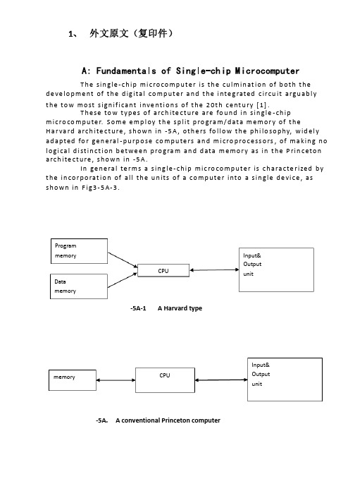
1、外文原文(复印件)A: Fundamentals of Single-chip MicrocomputerTh e si ng le-ch i p mi cr oc om pu ter is t he c ul mi nat i on o f bo th t h e d ev el op me nt o f th e d ig it al com p ut er an d t he int e gr at ed ci rc ui ta r gu ab ly th e t ow m os t s i gn if ic ant i nv en ti on s o f t h e 20t h c en tu ry[1].Th es e to w typ e s of a rc hi te ctu r e ar e fo un d i n s in gl e-ch ip m i cr oc om pu te r. So m e em pl oy t he sp l it p ro gr am/d ata me mo ry o f th e H a rv ar d ar ch it ect u re, sh ow n i n -5A, ot he rs fo ll ow th e ph i lo so ph y, w i de ly a da pt ed fo r g en er al-p ur pos e c om pu te rs an d m i cr op ro ce ss or s, o f m a ki ng no lo gi c al di st in ct io n b e tw ee n p ro gr am a n d da t a m em ory a s i n th e Pr in cet o n ar ch it ec tu re,sh ow n in-5A.In g en er al te r ms a s in gl e-chi p m ic ro co mp ut er i sc h ar ac te ri zed b y the i nc or po ra tio n of al l t he uni t s o f a co mp ut er i n to a s in gl e dev i ce, as s ho wn in Fi g3-5A-3.-5A-1 A Harvard type-5A. A conventional Princeton computerFig3-5A-3. Principal features of a microcomputerRead only memory (ROM).R OM i s u su al ly f or th e p er ma ne nt, n o n-vo la ti le s tor a ge o f an a pp lic a ti on s pr og ra m .M an ym i cr oc om pu te rs an d mi cr oc on tr ol le r s a re in t en de d fo r h ig h-v ol ume a p pl ic at io ns a nd h en ce t he e co nom i ca l ma nu fa ct ure of t he d ev ic es r e qu ir es t ha t the co nt en ts o f the pr og ra m me mo ry b e co mm it te dp e rm an en tl y d ur in g th e m an uf ac tu re o f c hi ps . Cl ear l y, th is im pl ie sa ri g or ou s a pp roa c h t o R OM co de d e ve lo pm en t s in ce c ha ng es ca nn otb e m ad e af te r man u fa ct ur e .T hi s d e ve lo pm en t pr oce s s ma y in vo lv e e m ul at io n us in g a s op hi st ic at ed deve lo pm en t sy st em w i th a ha rd wa re e m ul at io n ca pa bil i ty a s we ll a s th e u se of po we rf ul so ft wa re t oo ls.So me m an uf act u re rs p ro vi de ad d it io na l RO M opt i on s byi n cl ud in g i n th ei r ra ng e de vi ce s wi th (or i nt en de d fo r us e wi th) u s er pr og ra mm ab le m em or y. Th e s im p le st of th es e i s us ua ll y d ev ice w h ic h ca n op er ate in a m ic ro pr oce s so r mo de b y usi n g so me o f th e i n pu t/ou tp ut li ne s as a n ad dr es s an d da ta b us f or acc e ss in g e xt er na l m e mo ry. T hi s t ype o f d ev ic e c an b e ha ve fu nc ti on al l y a s t he si ng le c h ip mi cr oc om pu te r fr om wh ic h i t i s de ri ve d a lb eit w it h r es tr ic ted I/O an d a mo di fie d e xt er na l ci rcu i t. T he u se o f t h es e RO Ml es sd e vi ce s is c om mo n e ve n in p ro du ct io n c ir cu it s wh er e t he v ol um e do es n o t ju st if y th e d e ve lo pm en t co sts of c us to m on-ch i p RO M[2];t he re c a n st il l b e a si g ni fi ca nt s a vi ng in I/O a nd ot he r c hi ps co mp ar ed t o a c on ve nt io nal mi cr op ro ce ss or b as ed c ir cu it. M o re e xa ctr e pl ac em en t fo r RO M d ev ic es c an b e o bt ai ne d in t he f o rm o f va ri an ts w i th 'pi gg y-ba ck'EP RO M(Er as ab le p ro gr am ma bl e ROM)s oc ke ts o rd e vi ce s w it h EP ROM i ns te ad o f R OM 。
电气工程及其自动化专业外文文献英文文献外文翻译方面
1、 外文原文(复印件)A: Fundamentals of Single-chip MicrocomputerT h e sin gle -ch ip mi c ro co m p u t e r is t h e cu lm in at io n of b ot h t h e d e ve lo p me nt of t h e d ig ita l co m p u t e r a n d t h e i nte g rated c ircu it a rgu ab l y t h e to w mo st s ign if i cant i nve nt i o n s of t h e 20t h c e nt u ry [1].T h ese to w t yp e s of arch ite ct u re are fo u n d in s in gle -ch ip m i cro co m p u te r. S o m e e mp l oy t h e sp l it p ro gra m /d at a m e m o r y of t h e H a r va rd arch ite ct u re , s h o wn in -5A , ot h e rs fo l lo w t h e p h i lo so p hy, wid e l y ad a p ted fo r ge n e ral -p u rp o se co m p u te rs an d m i cro p ro ce ss o rs , of m a kin g n o l o g i ca l d i st in ct i o n b et we e n p ro gra m an d d ata m e m o r y as in t h e P rin c eto n a rch ite ct u re , sh o wn in -5A.In ge n e ra l te r m s a s in g le -ch ip m ic ro co m p u t e r is ch a ra cte r ized b y t h e in co r p o rat io n of all t h e u n its of a co mp u te r into a s in gle d e vi ce , as s h o w n in F i g3-5A-3.-5A-1A Harvard type-5A. A conventional Princeton computerProgrammemory Datamemory CPU Input& Output unitmemoryCPU Input& Output unitResetInterruptsPowerFig3-5A-3. Principal features of a microcomputerRead only memory (ROM).RO M is u su a l l y fo r t h e p e r m an e nt , n o n -vo lat i le sto rage of an ap p l i cat io n s p ro g ram .M a ny m i c ro co m p u te rs a n d m i cro co nt ro l le rs are inte n d ed fo r h i gh -vo lu m e ap p l i cat io n s a n d h e n ce t h e e co n o m i cal man u fa c t u re of t h e d e vi ces re q u ires t h at t h e co nt e nts of t h e p ro gra m me mo r y b e co mm i ed p e r m a n e nt l y d u r in g t h e m a n u fa ct u re of c h ip s . C lea rl y, t h i s imp l ies a r i go ro u s ap p ro a ch to ROM co d e d e ve lo p m e nt s in ce ch an ges can n o t b e mad e af te r m an u fa ct u re .T h i s d e ve l o p m e nt p ro ces s m ay i nvo l ve e mu l at i o n u sin g a so p h ist icated d e ve lo p m e nt syste m wit h a h ard wa re e mu l at i o n capab i l it y as we ll as t h e u s e of p o we rf u l sof t war e to o l s.So m e m an u fa ct u re rs p ro vi d e ad d it i o n a l ROM o p t io n s b y in clu d in g in t h e i r ran ge d e v ic es w it h (o r inte n d ed fo r u s e wit h ) u se r p ro g ram m a b le m e mo r y. T h e s im p lest of t h e se i s u su a l l y d e v i ce wh i ch can o p e rat e in a m i cro p ro ce s so r mo d e b y u s in g s o m e of t h e in p u t /o u t p u t l in es as an ad d res s a n d d ata b u s fo r a cc es sin g exte rn a l m e m o r y. T h is t yp e o f d e vi ce can b e h ave f u n ct i o n al l y as t h e s in gle ch ip m i cro co m p u t e r f ro m wh i ch it i s d e ri ved a lb e it wit h re st r icted I/O an d a m o d if ied exte rn a l c ircu it. T h e u s e of t h e se RO M le ss d e vi ces i s co mmo n e ve n in p ro d u ct io n circu i ts wh e re t h e vo lu m e d o e s n ot ju st if y t h e d e ve lo p m e nt co sts of cu sto m o n -ch ip ROM [2];t h e re ca n st i ll b e a si gn if i cant sav in g in I/O an d o t h e r ch ip s co m pared to a External Timing components System clock Timer/ Counter Serial I/O Prarallel I/O RAM ROMCPUco nve nt io n al m i c ro p ro ces so r b ased circ u it. M o re exa ct re p l a ce m e nt fo rRO M d e v ice s can b e o b tain ed in t h e fo rm of va ria nts w it h 'p i g g y-b a c k'E P ROM(E rasab le p ro gramm ab le ROM )s o cket s o r d e v ice s w it h E P ROMin stead of ROM 。
电气专业毕业设计英文文献
hcihw yb stsinahcem eht fo sseldrager yaler tnerruc-revo na sa demret eb dluow serusaem evitcerroc gnitaitini dna noitidnoc eht gnizingocer rof ecived ehT .noitca laidemer ekat ot yrassecen si ti ,detarelot eb nac hcihw taht naht retaerg si enihcam a ro tiucric cirtcele na ot tnerruc eht fi ,elpmaxe roF .deilppa eb ya m hcihw sngised yaler eht fo tnednepedni etiuq era stiucric rewop cirtcele fo noitcetorp fo selpicnirp ehT .noitargetni yb gnipoleved noitacinummoc atad dna erusaem ,lortnoc ,tcetorp ,tnegilletni si gnikrowten ,noitaziretupmoc ot si ygcetorp enil retupmocorcim spoleved etutitsni hcraeseR noitamotuA rewop cirtcelE gnijnaN ehT .tnemevom tnemtsevni ,lasiarppa hguorht 4991 ni ,9891 ni rehtona retfa eno osla noitcetorp sremrofsnart fo knaB ?rotareneg eht dn a noitcetorp rotareneg eht ,noitcetorp msitengam sesol spoleved ygolonhceT dna ecneicS fo ytisrevinU gnohzauH dna ytisrevinU tsaehtuoS eht hcihw rotareneg eht ,tcepsa noitcetorp tnempiuqe niam eht nI .yaw eht evap ot retupmocorcim eht rof noitomorp eht detcetorp ,egap wen eht yrotsih noitcetorp yaler yrtnuoc ruo ni denepo sah ,]5[ metsys eht ni noitacilppa eht deniatbo dna ,lasiarppa eht hguorht tsrif ecived evitcetorp retupmocorcim enil noissimsnart eht depoleved etutitsni rewop cirtcele anihC htroN lanigiro eht 4891 ni .ecived evitcetorp retupmocorcim nrettap tnereffid eht ,elpicnirp tnereffid eht depoleved sah rehtona retfa eno etutitsni hcraeseR noitamotuA rewop cirtcelE gnijnaN eht dna ytisrevinU gniqgnohC eht ,ytisrevinU gnotoaiJ iahgnahS ,ytisrevinU n ijnaiT eht ,ytisrevinU gnotoaiJ na'iX ,etutitsni rewop cirtcele anihC htroN eht ,ytisrevinU tsaehtuoS eht ,ygolonhceT dna ecneicS fo ytisrevinU gnohzauH .noitcnuf s'rennurerof etutitsni draytruoc hcraeser cifitneics eht dna gninrael rehgih fo snoitutitsni eht ,]4[ s07 etal eht morf hcraeser noitcetorp yaler retupmoc eht detrats yleman yrtnuoc ruO .enil vk005 eht no dna vk022 ynam ni devom osla noitcetorp ycneuqerf hgih noitcerid epyt noitasnepmoc egatlov esahp tiucric detargetni s'tnempoleved noitarepooc tn alP noitamotuA rewop cirtcelE gnijnaN eht dna ytisrevinU nijnaiT eht ,]3[ elor laitneulfni eht detcetorp ycneuqerf hgih etutitsni hcraeseR noitamotuA rewop cirtcelE gnijnaN
(完整版)电气专业英文文献

An Expert System for Transformer Fault Diagnosis Using Dissolved Gas Analysis1. INTRODUCTIONThe power transformer is a major apparatus in a power system, and its correct functioning its vital to minimize system outages, many devices have evolved to monitor the serviceability of power transformers. These devices, such as, Buchholz relays or differential relays, respond only to a severe power failure requiring immediate removal of the transformer from service, in which case, outages are inevitable. Thus, preventive techniques for early detection faults to avoid outages would be valuable. In this way, analysis of the mixture of the faulty gases dissolved in insulation oil of power transformer has received worldwide recognition as an effective method for the detection of oncipient faults. Many researchers and electrical utilities have reported on their experience and developed interpretative criteria on the basis of DGA. However, criteria tend to vary from utility to utility. Therefore, transformer diagnosis is still in the heuristic stage. For this reason, knowledge-based programming is a suitable approach to implement in such a diagnostic problem.Based on the interpretation of DGA, a prototype of an expert system for diagnosis of suspected transformer faults and their maintenance procedures is proposed. The significant source in this knowledge base is the gas ratio method. Some limitations of this approach are overcome by incorporating the diagnostic procedure and the synthetic expertise method. Furthermore, data bases adopted from TPC'S gas records of transformers are incorporated into the expert system to increase the practical performance. Uncertainty of diagnosis is managed by using fuzzy set concepts. This expert system is constructed with rule based knowledge representation, since it can be expressed by experts. The expert system building tool,knowledge Engineering System(KES), is used in the development of the knowledge system because, it has excellent man-machine interface that provides suggestions. Moreover,its inference strategy is similar to the MYCIN. A famous rule-based expert system used for medical diagnosis. The uncertainty of human qualitative diagnostic expertise, e.g., key gasanalysis, and another quantitative imprecision, such as, norms threshold and gas ratio boundaries etc., are smoothed by appropriate fuzzy models. With the results of such implementation, different certainty factors will be assigned to the corresponding expertise variables. Both event-driven(forward chaining) and goal-driven (backward chaining) inferences are used in the inference engine to improve the inference efficiency. To demonstrate the feasibility of the proposed expert system, around hundreds of TPC historical gas records have been tested. It is found that more appropriate faulty types and maintenance suggestions can support the maintenance personals to increase the performance of transformer diagnosis.2. DEVELOPMENT OF DIAGNOSIS AND INTERPRETATIONLike many diagnostic problems, diagnosis of oil-immersed power transformer is a skilled task. A transformer may function well externally with monitors, while some incipient deterioration may occur internally to cause a fatal problem in the latter development. According to a Japanese experience, nearly 80% of all faults result from incipient deteriorations. Therefore, faults should be identified and avoided at the earliest possible stage by some predictive maintenance technique. DGA is one of the most popular techniques for this problem. Fault gases in transformers are generally produced by oil degradation and other insulating material, e.g., cellulose and paper. Theoretically, if an incipient or active fault is present, the individual dissolved gas concentration, gassing rate, total combustible gas(TCG) and cellulose degradation are all significantly increased. By using gas chromatography to analyse the gas dissolved in a transformer's insulating oil, it becomes feasible to judge the incipient fault types. This study is concerned with the following representative combustible gases; hydrogen(H2), methane(C2H2), ethane(C2H6), ethylene(C2H2) and carbon monoxide(C0).Many interpretative methods based on DGA to the nature of incipient deterioration have been reported. Even under normal transformer operational conditions, some of these gases may be formed inside. Thus, it is necessary to build concentration norms from a sufficiently large sampling to assess the statistics. TPC investigated gas data from power transformers to construct its criteria. The developedknowledge base in this paper is partially based on these data. On the hand, Dornerburg developed a method to judge different faults by rating pairs of concentrations of gases, e.g., CH/H, GH/C3H4, with approximately equal solubility and fusion coefficients. Rogers established mare comprehensive ratio codes to interpret the thermal fault types with theoretical thermodynamic assessments. This gas ratio method was promising because it eliminated the effect of oil volume and simplified the choice of units. Moreover, it systematically classified the diagnosis expertise in a table form. Table 1 displays the ratio method as proposed by Rogers. The dissolved gas may vary with the nature and severity of different faults. By analyzing the energy density of faults, it's possible to distinguish three basic fault processes:overheating(pyrolysis), corona(partial dischatge) and arcing discharge. Corona and arcing arise from electrical faults, while overheating is a thermal fault. Both types of faults my lead to deterioration, while damage from overheating is typically less than that from electrical stress. Infect, different gas trends lead to different faulty types, the key gas method is identified. For example, large amounts of CH and H are produced with minor arcing fault 4 quantities of CH 2aid C2H2 may bea symptom of an arcing fault.3.THE PROPOSED DIAGNOSTIC EXPERT SYSTEMThis study is aimed at developing a rule-based expert system to perform transformer diagnosis similar to a human expert. The details of system processing are described below.3.1 The Proposed Diagnostic MethodDiagnosis is a task that requires experience. It is unwise to determine an approach from only a few investigations. Therefore, this study uses the synthetic expertise method with the experienced procedure to assist the popular gas ratio method and complete practical performance.3.1.1 Experienced Diagnostic ProcedureThe overall procedure of routine maintenance for transformers is listed. The core of this procedure is based on the implementation of the DGA technique. The gas ratio method is the significant knowledge source. Some operational limitations of the gasratio method exist. The ratio table is unable to cover all possible cases. Minimum levels of gases must be present. The solid insulation involving CO and CO are handled separately and the gas ratio codes have been developed mainly from a free-breathing transformer. Other diagnostic expertise should be used to assist this method. Norms, synthetic expertise method and data base records have been incorporated to complete these limitations. The first step of this diagnostic procedure begins by asking DGA for an oil sample to be tested. More important relevant information about the transformer's condition, such as the voltage level, the preservative type, the on-line-tap-changer(OLTC) state, the operating period and degassed time must be known for further inference. Norms(criteria) Set up by TPC power transformers' gas characteristic data are then used to judge the transformers' condition. For the abnormal cases, the gas ratio method is used to diagnose transformer fault type. If different or unknown diagnosis results are found from these ratio methods, a further synthetic expertise method is adopted. After these procedures, different severity degrees are assigned to allow appropriate corresponding maintenance suggestions.3.1.2 Synthetic Expertise MethodThe ratio trend, norms threshold, key gas analysis and some expertise are considered as different evidences to confirm some special fault types. In other words, more significant evidences have been collected for some special fault type, better assessment of the transformer status is obtained.The ratio trend can be seen as a modification of the conventional gas ratio and key gas method.Obviously, the above gas trends should be incorporated with other evidences under the experienced procedure for practical use. Norms threshold, the gassing rate, the quantity of total combustible gas(TCG), the TPC maintenance expertise and the fuzzy set assignment are all important evidences considered in the synthetic diagnosis.Other expertise based on a transformer historical data base is also used to analyse the characteristics of a case transformer. Section 3.4 gives some details of these rules.3.2 Expert System StructureThe proposed diagnostic expert system is composed of components, working memory, a knowledge base, an inference engine and a man-machine interface. Working memory (global data base) contains the current data relevant to solve the present problem. In this study, most of the diagnostic variables stored in the data base are current gas concentration, some are from the user, others are retrieved from the transformer's historical data base. Note that the fuzzy set concept is incorporated to create fuzzy variables on the request of system reasoning. A knowledge relationship, which uses these facts, as the basis for decision making. The production rule used in this system is expressed in IF-THEN forms. A successful expert system depends on a high quality knowledge base. For this transformer diagnostic system, the knowledge base incorporates some popular interpretative methods of DGA, synthetic expertise method and heuristic maintenance rules. Section 3.4 will describe this knowledge base. Another special consideration in the expert system is its inference engine. The inference engine controls the strategies of reasoning and searching for appropriate knowledge. The reasoning strategy employs both forward chaining(data-driven) and backward chaining(goal-driven). Fuzzy rules, norms rules, gas ratio rules, synthetic expertise rules and some of the maintenance rules and some maintenance rules, use forward chaining.As for the searching strategy in KES, the depth first searching and short-circuit evaluation are adopted. The former can improve the search efficiency by properly arranging the location of significant rules in the inference procedures. The latter strategy only searches the key conditional statements in the antecedent that are responsible for establishing whether the entire rule is true or false. Taking the advantages of these two approaches in the building and structuring of a knowledge base improves inference efficiency significantly.As for man-machine interface. KES has an effective interface which is better than typical knowledge programming languages, such as, PROLOG or LISP. With the help of this interface, the capability of tracing, explaining and training in an expert system is greatly simplified.4.IMPLEMENTATION OF THE PROPOSED EXPERT SYSTEMAn expert system is developed based on the proposed interpretative rules and diagnostic procedures of the overall system. To demonstrate the feasibility of this expert system in diagnosis, the gas data supported by MTL of TPC have been tested. In Taiwan, the MTL of TPC performs the DGA and sends the results to all acting divisions relating to power transformers. In return, these acting divisions are requested to collect and supply their transformer oil samples periodically.After analysing oil samples, more than ten years' worthy gas records are collected and classified into three voltage level, 69KV, 16KV and 345KV. Thus, gas records for one transformer are composed of several groups of data. In the process of DGA interpretation, all of these data may be considered, but only the recent data which have significant effects on diagnosis are listed in the later demonstration. In MTL, all gas concentrations are expressed by pm in volume concentration. 100 pm is equal to 0.01 ml(gas)/100ml(oil).From the expertise of diagnosis, the normal state can be confirmed only by inspection of the transformer's norms level. In practice, most of the transformer oil samples are normal, and this can be inferred successfully on the early execution of this expert system. However, the Success of an expert system is mainly dependent on the capability of diagnosis for the transformers in question. In the implementation, many gas records which are in abnormal condition are chosen to test the Justification of this diagnostic system. A total of 101 transformer records have been executed and the results are summarized in Table 5. Among those implemented, three are listed and demonstrated.Shown in Table 5 are the results of 101 units of transformers in three types of remedy: normal, thermal fault and arc fault. After comparing them with the actual state and expert judgement, a summary of results was obtained. As previously stated, one unit of transformer may include many groups of gas data. In evaluation, we depicted some key groups in one unit to justify because some transformers may have different incipient faults during different operational stages. Some mistakes implemented from testing are caused by the remaining oil in the oil sampling container, unstable gas characteristics of the new degassing sample and some obscuregas types. If more information or new techniques support other uncertain membership functions, they can be added into the knowledge has to enlarge the the performance of this prototype expert system. Furthermore, the parameters described in table 2,3 and 4 are suitable for TPC power transformer. Different regions may be modified the maintenance personnel find more suitable system parameters.5.CONCLUSIONSA prototype expert system is developed on a personal computer using KES. It can diagnose the incipient faults of the suspected transformers and suggest proper maintenance actions. Fuzzy set concept is used to handle uncertain norms thresholds, gas ratio boundaries and key gas analysis. The synthetic method and diagnostic procedure are proposed to assist the situation which can not be handled properly by the gas ratio methods. Results from the implementation of the expert system shows that the expert system is a useful tool to assist human expert and maintenance engineers.The knowledge base of this expert system is incorporated within the popular interpretative method of DGA, synthetic expertise and heuristic maintenance rules. The data base supported by TPC MTL for about 10 year collection of transformer inspection data is also used to improve the interpretation of diagnosis. Through the development of the proposed expert system, the expertise of TPC MTL can be reserved. In addition, this work can be continued to expand the knowledge base by adding any new experience, measurement and analysis techniques.。
电气专业英文文献

Fire FightingAlong with the our country economic development rapid development, the lives of the people level unceasing enhancement, the city uses to be day by day anxious, urges the building to face the direction is developing. This kind of high level civil construction repair needed materials and the way also more hasten the diversification, and along with uses electricity the load and coal gas consumption quantity enlarging, proposed to the fire auto-alarm system design is higher, a stricter request. In order to guarantee the people life and property the security, the fire auto-alarm system design has become in the high level civil construction design one of most important design contents. Presently based on the author fire of auto-alarm system design overseeing work in the high level civil building experience, proposed in present national related standard and standard unclear true detail shallow opinion, by for the colleagues to discuss and to point out mistakes.First, design basisThe fire auto-alarm system design is a specialized very strong technology work, at the same time also has the very strong policy-type. Therefore, first should be clear about the following design basis:1st, must grasp the architectural design fire protection standard, the system design standard, the equipment manufacture standard, the installment construction approval standard and the administration laws and regulations and so on five big aspects fire laws and regulations, and in practical understanding present country related standard and standard positive word: "Must", "be supposed", "to be suitable", "may" and the reverse side word: "Strictly prohibits", "should not", "not have", "not to be suitable" the meaning. 2nd, must aim at high level civil building function, use and the protection object fire protection rank, earnestly carries out the present national related standard and the standard, earnestly treats the public security fire prevention surveillance department the examination and approval opinion.Second, fire auto-alarm system equipment establishmentFire detector establishmentOpens wide either the seal or the stair hall should alone divide the search coverage, and each 2 ~ 3 establish a fire detector.The first room (including guards against in front of smoke stair hall in front of room, fire elevator room, fire elevator with guards against the front room which smoke stair hall comes in handy) and the aisle should distinguish alone to divide the search coverage, specially front the room and the lift well, the scattered stair hall and the aisle are interlinked, has time the fire haze to be easier to gather or to flow, is the personnel disperses which saves goal with the fire prevention, therefore should install the fire detector. Regarding common elevator in front of room although is not the personnel disperses , butthis front room and the lift well are interlinked, has time the fire haze to be also easy to gather or to flow, suitably alone divides the search coverage and installs the fire detector.The electric cable shaft therefore is easy to form pulls out the smoke inflammation the channel; Has when the fire the fire intensity not easily extends along the electric cable burns, for this, "the high level civil construction design fire protection standard" and "the civil construction electricity design standard" separately proposes the detailed specific stipulation in the construction and in the electric wire or on the electric cable shaping. But considered implements specifically the difficulty and the present situation, the electric cable shaft installs the fire detector is extremely essential, and coordinates the shaft the fire protection separation request, each 2 ~ 3 or each level installs.The elevator machine room should install the fire detector, its elevator is the important vertical transportation vehicle; Its two elevator machine room has has the fire risk; Its three lift well existence essential opens the hole, like the level gate opens between the hole, the air vent, the between permanence opens the hole with the elevator machine room or the pulley and so on; Its four when has the fire, the lift well often becomes the fire intensity spread the channel, is easy to threaten the elevator machine room the facility. Therefore, the elevator machine room establishes the fire detector is necessary, crown of also suitable establishment fire detector lift well.2nd, the manual fire reports to the police the button establishment (Including guards against in front of smoke stair hall in view of various floors front room in front of room, fire elevator room, fire elevator with guards against which smoke stair hall to come in handy the front room) is has when the fire the personnel to disperse which saves goal with fire prevention, should report to the police the button first choice spot as the establishment manual fire. In addition, the room also should establish the manual fire to the common elevator in front of to report to the police the button.In the public active place (including hall, hall, dining room, multi-purpose hall and so on) and the main thoroughfare and so on place, the personnel very is all centralized, and mainly disperses the channel. Therefore should report to the police the button in these public active places main access establishment manual fires; The manual fire establishes which in the main thoroughfare reports to the police the button to guarantee "to a manual fire which most is close to reports to the police the button distance from a fire protection district any position not to be supposed to be bigger than 30 meters".3rd, the fire emergency broadcasts the speaker the establishmentThe aisle, the hall, the dining room and so on the public place personnel very are all centralized, and mainly disperses the channel. Therefore should press in these public places "to a recent speaker distance is not bigger than 25 meters from a fire protection district any spot" and "in the aisle last should not be bigger than 12.5 meters the speaker to the aisle terminal distance" the establishment fire emergency to broadcast the speaker; Next also should establish the fire in the public bathroom place emergency to broadcast the speaker.The first room (including guards against in front of smoke stair hall in front of room, fire elevator room, fire elevator with guards against which smoke stair hall to come in handy the front room) is has when the fire the personnel to disperse which saves goal with fire prevention, also has the fire door separation and the sounds of people is confused and noisy, therefore should establish the fire emergency to broadcast the speaker. In front of the common elevator the room also should establish the fire emergency to broadcast the speaker. Disperses the stair hall also is has when the fire the personnel to disperse which saves goal with the fire prevention, also the sounds of people are confused and noisy, therefore should establish the fire emergency to broadcast the speaker, by favors the fire emergency broadcast to disperse the instruction.4th, fire alarm installment establishmentThe establishment fire emergency broadcast fire auto-alarm system, the author thought also should install the fire alarm installment, but its control procedure should be: The alarm apparatus should confirm after the fire, uses manual or the automatic control mode unification to the fire correlation region transmission warning, stops the alarm apparatus work in the stipulation time, the rapid linkage fire emergency broadcast and broadcasts to the people disperses the instruction.The fire alarm installment establishment position, the author thought should report to the police the button position with the manual fire to be same, its wall surface installment should for be apart from the ground 1.8 meters highly5th, fire special use telephone establishmentInstalls the fire special use telephone extension telephone, should be located the engine room which related also some people is on duty frequently with the fire linkage control (including fire water plant, spare electricity generation engine room, matches substation, mainly ventilates with air conditioning engine room, discharges fume engine room, fire prevention elevator machine room and other), the fire fighting control system operates the equipment place or the control room, the fire duty officers observation room, the security manages spot and so on public room. Sedan of theater box the fire elevatorand in the ordinary elevator all should suppose the special use telephone, requests the elevator machine room and the elevator sedan theater box, the elevator machine room and the fire control room, the elevator sedan theater box and the fire control room and so on three compositions is reliable to speaks the correspondence telephone system. Usually in fire control room; The establishment elevator monitoring demonstration plate (including position indicator, direction indicating lamp, to speaks correspondence telephone, trouble lamp and so on), in order to carries on the necessity to the elevator running status which in the surveillance and the emergency case controls.Is equipped with the manual fire to report to the police position and so on button, fire hydrant button also should install the fire special use telephone receptacle.Third, fire linkage control1st, the fire linkage control should include the control fire pump to open, to stop, also should demonstrate opens pumps the button the position and the fire pump work and the malfunction. When the fire hydrant is equipped with the fire hydrant button, its electric installation work spot also should demonstrate the fire pump the working mode active status (namely establishment fire pump work indicating lamp).2nd, the fire linkage control should include the control spraying of water and the water atomization fire fighting system opens, stops, also should demonstrate the fire pump the work and the malfunction and the fluent display, reports to the police the valve, the safety signal valve working mode active status. In addition, to the basin, the water tank water level also should carry on the demonstration monitor; In order to prevent the overhaul signal valve is shut down, the author thought should use the belt electric signal the control signal valve by to demonstrate it opens the condition.3rd, the fire linkage control other controls and the demonstration function, should carry out the present national related standard and the standard specific stipulation.Fourth, fire auto-alarm system wiringIn order to prevent the fire occurs when the fire control, the correspondence and the warning line severance, causes the fire fighting work to be unable to carry on, creates the bigger economic loss; Also for the suppression electronmagetic interference (for example transformer, electric motor, electric cable and so on) the influence which produces to the fire auto-alarm system. The fire auto-alarm system transmission line and the fire control, the correspondence and the warning line should use the being flame-resistant electric cable, and should use the metal tube or the enclosed metal trunking protection. The fire manual positive governing installment line should use the fireproof electric cable, its electric cable also should use the metal tube or theenclosed metal trunking protection. Uses Ming Fushi, should takes the fire protection protective measures on the metal tube or the enclosed metal trunking.Fifth, concluding remarkThe author rests on the concrete project to implement the experience, elaborated the design basis, fire auto-alarm design actual problem and so on system equipment establishment, fire linkage control and its wiring pulls out some shallow opinions, its goal is enhances the fire auto-alarm system the design quality, discovered early and the notification fire, prevented and reduces the fire to harm, by protects the person and the property safety.。
电气专业英文文献

电气专业英文文献————————————————————————————————作者:————————————————————————————————日期:An Expert System for Transformer Fault Diagnosis Using Dissolved Gas Analysis1. INTRODUCTIONThe power transformer is a major apparatus in a power system, and its correct functioning its vital to minimize system outages, many devices have evolved to monitor the serviceability of power transformers. These devices, such as, Buchholz relays or differential relays, respond only to a severe power failure requiring immediate removal of the transformer from service, in which case, outages are inevitable. Thus, preventive techniques for early detection faults to avoid outages would be valuable. In this way, analysis of the mixture of the faulty gases dissolved in insulation oil of power transformer has received worldwide recognition as an effective method for the detection of oncipient faults. Many researchers and electrical utilities have reported on their experience and developed interpretative criteria on the basis of DGA. However, criteria tend to vary from utility to utility. Therefore, transformer diagnosis is still in the heuristic stage. For this reason, knowledge-based programming is a suitable approach to implement in such a diagnostic problem.Based on the interpretation of DGA, a prototype of an expert system for diagnosis of suspected transformer faults and their maintenance procedures is proposed. The significant source in this knowledge base is the gas ratio method. Some limitations of this approach are overcome by incorporating the diagnostic procedure and the synthetic expertise method. Furthermore, data bases adopted from TPC'S gas records of transformers are incorporated into the expert system to increase the practical performance. Uncertainty of diagnosis is managed by using fuzzy set concepts. This expert system is constructed with rule based knowledge representation, since it can be expressed by experts. The expert system building tool,knowledge Engineering System(KES), is used in the development of the knowledge system because, it has excellent man-machine interface that provides suggestions. Moreover,its inference strategy is similar to the MYCIN. A famous rule-based expert system used for medical diagnosis. The uncertainty of human qualitative diagnostic expertise, e.g., key gasanalysis, and another quantitative imprecision, such as, norms threshold and gas ratio boundaries etc., are smoothed by appropriate fuzzy models. With the results of such implementation, different certainty factors will be assigned to the corresponding expertise variables. Both event-driven(forward chaining) and goal-driven (backward chaining) inferences are used in the inference engine to improve the inference efficiency. To demonstrate the feasibility of the proposed expert system, around hundreds of TPC historical gas records have been tested. It is found that more appropriate faulty types and maintenance suggestions can support the maintenance personals to increase the performance of transformer diagnosis.2. DEVELOPMENT OF DIAGNOSIS AND INTERPRETATIONLike many diagnostic problems, diagnosis of oil-immersed power transformer is a skilled task. A transformer may function well externally with monitors, while some incipient deterioration may occur internally to cause a fatal problem in the latter development. According to a Japanese experience, nearly 80% of all faults result from incipient deteriorations. Therefore, faults should be identified and avoided at the earliest possible stage by some predictive maintenance technique. DGA is one of the most popular techniques for this problem. Fault gases in transformers are generally produced by oil degradation and other insulating material, e.g., cellulose and paper. Theoretically, if an incipient or active fault is present, the individual dissolved gas concentration, gassing rate, total combustible gas(TCG) and cellulose degradation are all significantly increased. By using gas chromatography to analyse the gas dissolved in a transformer's insulating oil, it becomes feasible to judge the incipient fault types. This study is concerned with the following representative combustible gases; hydrogen(H2), methane(C2H2), ethane(C2H6), ethylene(C2H2) and carbon monoxide(C0).Many interpretative methods based on DGA to the nature of incipient deterioration have been reported. Even under normal transformer operational conditions, some of these gases may be formed inside. Thus, it is necessary to build concentration norms from a sufficiently large sampling to assess the statistics. TPC investigated gas data from power transformers to construct its criteria. The developedknowledge base in this paper is partially based on these data. On the hand, Dornerburg developed a method to judge different faults by rating pairs of concentrations of gases, e.g., CH/H, GH/C3H4, with approximately equal solubility and fusion coefficients. Rogers established mare comprehensive ratio codes to interpret the thermal fault types with theoretical thermodynamic assessments. This gas ratio method was promising because it eliminated the effect of oil volume and simplified the choice of units. Moreover, it systematically classified the diagnosis expertise in a table form. Table 1 displays the ratio method as proposed by Rogers. The dissolved gas may vary with the nature and severity of different faults. By analyzing the energy density of faults, it's possible to distinguish three basic fault processes:overheating(pyrolysis), corona(partial dischatge) and arcing discharge. Corona and arcing arise from electrical faults, while overheating is a thermal fault. Both types of faults my lead to deterioration, while damage from overheating is typically less than that from electrical stress. Infect, different gas trends lead to different faulty types, the key gas method is identified. For example, large amounts of CH and H are produced with minor arcing fault 4 quantities of CH 2aid C2H2 may bea symptom of an arcing fault.3.THE PROPOSED DIAGNOSTIC EXPERT SYSTEMThis study is aimed at developing a rule-based expert system to perform transformer diagnosis similar to a human expert. The details of system processing are described below.3.1 The Proposed Diagnostic MethodDiagnosis is a task that requires experience. It is unwise to determine an approach from only a few investigations. Therefore, this study uses the synthetic expertise method with the experienced procedure to assist the popular gas ratio method and complete practical performance.3.1.1 Experienced Diagnostic ProcedureThe overall procedure of routine maintenance for transformers is listed. The core of this procedure is based on the implementation of the DGA technique. The gas ratio method is the significant knowledge source. Some operational limitations of the gasratio method exist. The ratio table is unable to cover all possible cases. Minimum levels of gases must be present. The solid insulation involving CO and CO are handled separately and the gas ratio codes have been developed mainly from a free-breathing transformer. Other diagnostic expertise should be used to assist this method. Norms, synthetic expertise method and data base records have been incorporated to complete these limitations. The first step of this diagnostic procedure begins by asking DGA for an oil sample to be tested. More important relevant information about the transformer's condition, such as the voltage level, the preservative type, the on-line-tap-changer(OLTC) state, the operating period and degassed time must be known for further inference. Norms(criteria) Set up by TPC power transformers' gas characteristic data are then used to judge the transformers' condition. For the abnormal cases, the gas ratio method is used to diagnose transformer fault type. If different or unknown diagnosis results are found from these ratio methods, a further synthetic expertise method is adopted. After these procedures, different severity degrees are assigned to allow appropriate corresponding maintenance suggestions.3.1.2 Synthetic Expertise MethodThe ratio trend, norms threshold, key gas analysis and some expertise are considered as different evidences to confirm some special fault types. In other words, more significant evidences have been collected for some special fault type, better assessment of the transformer status is obtained.The ratio trend can be seen as a modification of the conventional gas ratio and key gas method.Obviously, the above gas trends should be incorporated with other evidences under the experienced procedure for practical use. Norms threshold, the gassing rate, the quantity of total combustible gas(TCG), the TPC maintenance expertise and the fuzzy set assignment are all important evidences considered in the synthetic diagnosis.Other expertise based on a transformer historical data base is also used to analyse the characteristics of a case transformer. Section 3.4 gives some details of these rules.3.2 Expert System StructureThe proposed diagnostic expert system is composed of components, working memory, a knowledge base, an inference engine and a man-machine interface. Working memory (global data base) contains the current data relevant to solve the present problem. In this study, most of the diagnostic variables stored in the data base are current gas concentration, some are from the user, others are retrieved from the transformer's historical data base. Note that the fuzzy set concept is incorporated to create fuzzy variables on the request of system reasoning. A knowledge relationship, which uses these facts, as the basis for decision making. The production rule used in this system is expressed in IF-THEN forms. A successful expert system depends on a high quality knowledge base. For this transformer diagnostic system, the knowledge base incorporates some popular interpretative methods of DGA, synthetic expertise method and heuristic maintenance rules. Section 3.4 will describe this knowledge base. Another special consideration in the expert system is its inference engine. The inference engine controls the strategies of reasoning and searching for appropriate knowledge. The reasoning strategy employs both forward chaining(data-driven) and backward chaining(goal-driven). Fuzzy rules, norms rules, gas ratio rules, synthetic expertise rules and some of the maintenance rules and some maintenance rules, use forward chaining.As for the searching strategy in KES, the depth first searching and short-circuit evaluation are adopted. The former can improve the search efficiency by properly arranging the location of significant rules in the inference procedures. The latter strategy only searches the key conditional statements in the antecedent that are responsible for establishing whether the entire rule is true or false. Taking the advantages of these two approaches in the building and structuring of a knowledge base improves inference efficiency significantly.As for man-machine interface. KES has an effective interface which is better than typical knowledge programming languages, such as, PROLOG or LISP. With the help of this interface, the capability of tracing, explaining and training in an expert system is greatly simplified.4.IMPLEMENTATION OF THE PROPOSED EXPERT SYSTEMAn expert system is developed based on the proposed interpretative rules and diagnostic procedures of the overall system. To demonstrate the feasibility of this expert system in diagnosis, the gas data supported by MTL of TPC have been tested. In Taiwan, the MTL of TPC performs the DGA and sends the results to all acting divisions relating to power transformers. In return, these acting divisions are requested to collect and supply their transformer oil samples periodically.After analysing oil samples, more than ten years' worthy gas records are collected and classified into three voltage level, 69KV, 16KV and 345KV. Thus, gas records for one transformer are composed of several groups of data. In the process of DGA interpretation, all of these data may be considered, but only the recent data which have significant effects on diagnosis are listed in the later demonstration. In MTL, all gas concentrations are expressed by pm in volume concentration. 100 pm is equal to 0.01 ml(gas)/100ml(oil).From the expertise of diagnosis, the normal state can be confirmed only by inspection of the transformer's norms level. In practice, most of the transformer oil samples are normal, and this can be inferred successfully on the early execution of this expert system. However, the Success of an expert system is mainly dependent on the capability of diagnosis for the transformers in question. In the implementation, many gas records which are in abnormal condition are chosen to test the Justification of this diagnostic system. A total of 101 transformer records have been executed and the results are summarized in Table 5. Among those implemented, three are listed and demonstrated.Shown in Table 5 are the results of 101 units of transformers in three types of remedy: normal, thermal fault and arc fault. After comparing them with the actual state and expert judgement, a summary of results was obtained. As previously stated, one unit of transformer may include many groups of gas data. In evaluation, we depicted some key groups in one unit to justify because some transformers may have different incipient faults during different operational stages. Some mistakes implemented from testing are caused by the remaining oil in the oil sampling container, unstable gas characteristics of the new degassing sample and some obscuregas types. If more information or new techniques support other uncertain membership functions, they can be added into the knowledge has to enlarge the the performance of this prototype expert system. Furthermore, the parameters described in table 2,3 and 4 are suitable for TPC power transformer. Different regions may be modified the maintenance personnel find more suitable system parameters.5.CONCLUSIONSA prototype expert system is developed on a personal computer using KES. It can diagnose the incipient faults of the suspected transformers and suggest proper maintenance actions. Fuzzy set concept is used to handle uncertain norms thresholds, gas ratio boundaries and key gas analysis. The synthetic method and diagnostic procedure are proposed to assist the situation which can not be handled properly by the gas ratio methods. Results from the implementation of the expert system shows that the expert system is a useful tool to assist human expert and maintenance engineers.The knowledge base of this expert system is incorporated within the popular interpretative method of DGA, synthetic expertise and heuristic maintenance rules. The data base supported by TPC MTL for about 10 year collection of transformer inspection data is also used to improve the interpretation of diagnosis. Through the development of the proposed expert system, the expertise of TPC MTL can be reserved. In addition, this work can be continued to expand the knowledge base by adding any new experience, measurement and analysis techniques.。
电气英文文献+翻译

POWER SUPPLY AND DISTRIBUTION SYSTEMABSTRACTThe basic function of the electric power system is to transport the electric power towards customers. The l0kV electric distribution net is a key point that connects the power supply with the electricity using on the industry, business and daily-life. For the electric power, allcostumers expect to pay the lowest price for the highest reliability, but don't consider that it's self-contradictory in the co-existence of economy and reliable.To improve the reliability of the power supply network, we must increase the investment cost of the network construction But, if the cost that improve the reliability of the network construction, but the investment on this kind of construction would be worthless if the reducing loss is on the power-off is less than the increasing investment on improving the reliability .Thus we find out a balance point to make the most economic,between the investment and the loss by calculating the investment on power net and the loss brought from power-off.KEYWARDS:power supply and distribution,power distribution reliability,reactive compensation,load distributionTEXTThe revolution of electric power system has brought a new big round construction,which is pushing the greater revolution of electric power technique along with the application of new technique and advanced equipment. Especially, the combination of the information technique and electric power technique, to great ex- tent, has improved reliability on electric quality and electric supply. The technical development decreases the cost on electric construction and drives innovation of electric network. On the basis of national and internatio- nal advanced electric knowledge, the dissertation introduces the research hotspot for present electric power sy- etem as following.Firstly, This dissertation introduces the building condition of distribution automation(DA), and brings forward two typical construction modes on DA construction, integrative mode and fission mode .It emphasize the DA structure under the condition of the fission mode and presents the system configuration, the main station scheme, the feeder scheme, the optimized communication scheme etc., which is for DA research reference.Secondly, as for the (DA) trouble measurement, position, isolation and resume, This dissertation analyzes the changes of pressure and current for line problem, gets math equation by educing phase short circuit and problem position under the condition of single-phase and works out equation and several parameter s U& , s I& and e I& table on problem . It brings out optimized isolation and resume plan, realizes auto isolation and network reconstruction, reduces the power off range and time and improves the reliability of electric power supply through problem self- diagnoses and self-analysis. It also introduces software flow and use for problem judgement and sets a model on network reconstruction and computer flow.Thirdly, electricity system state is estimated to be one of the key techniques in DA realization. The dissertation recommends the resolvent of bad measurement data and structure mistake on the ground of describing state estimate way. It also advances a practical test and judging way on topology mistake in state estimate about bad data test and abnormity in state estimate as well as the problem and effect on bad data from state measure to state estimate .As for real time monitor and control problem, the dissertation introduces a new way to solve them by electricity break and exceptional analysis, and the way has been tested in Weifang DA.Fourthly, about the difficulty for building the model of load forecasting, big parameter scatter limit and something concerned, the dissertation introduces some parameters, eg. weather factor, date type and social environment effect based on analysis of routine load forecasting and means. It presents the way for electricity load forecasting founded on neural network(ANN),which has been tested it’s validity by example and made to be good practical effect.Fifthly, concerning the lack of concordant wave on preve nting concordant wave and non-power compensation and non-continuity on compensation, there is a topology structure of PWM main circuit and nonpower theory on active filter the waves technique and builds flat proof on the ground of Saber Designer and proves to be practical. Meanwhile, it analyzes and designs the way of non-power need of electric network tre- nds and decreasing line loss combined with DA, which have been tested its objective economic benefit throu- gh counting example.Sixthly, not only do the dissertation design a way founded on the magrginal electric price fitted to our present national electric power market with regards to future trends of electric power market in China and fair trade under the government surveillance, that is group competitio n in short-term trade under the way of grouped price and quantity harmony, but also puts forward combination arithmetic, math model of trading plan and safty economical restriction. It can solve the original contradiction between medium and long term contract price and short term competitive price with improvement on competitive percentage and cut down the unfair income difference of electric factory, at the same time, it can optimize the electric limit for all electricfactories and reduce the total purchase charge of electric power from burthen curve of whole electric market network.The distribution network is an important link among the power system. Its neutral grounding mode and operation connects security and stability of the power system directly. At the same time, the problem about neutral grounding is associated with national conditions, natural environment, device fabrication and operation. For example, the activity situation of the thunder and lightning, insulating structure and the peripheral interference will influence the choice of neutral grounding mode Conversely, neutral grounding mode affects design, operation, debugs and developing. Generally in the system higher in grade in the voltage, the insulating expenses account for more sizable proportion at the total price of the equipment. It is very remarkable to bring the economic benefits by reducing the insulating level. Usually such system adopt the neutral directly grounding and adopt the autoreclosing to guarantee power supply reliability. On the contrary, the system which is lower in the voltage adopts neutral none grounding to raise power supply reliability. So it is an important subject to make use of new- type earth device to apply to the distribution network under considering the situation in such factors of various fields as power supply reliability, safety factor, over-voltage factor, the choice of relay protection, investment cost, etc.The main work of this paper is to research and choice the neutral grounding mode of the l0kV distribution network. The neutral grounding mode of the l0kV network mainly adopts none grounding, grounding by arc suppressing coil, grounding by reactance grounding and directly grounding. The best grounding mode is confirmed through the technology comparison. It can help the network run in safety and limit the earth electric arc by using auto-tracking compensate device and using the line protection with the detection of the sensitive small ground current. The paper introduces and analyzes the characteristic of all kind of grounding modes about l0kV network at first. With the comparison with technological and economy, the conclusion is drawn that the improved arc suppressing coil grounding mode shows a very big development potential.Then, this paper researches and introduces some operation characteristics of the arc suppressing coil grounding mode of the l0kV distribution network. And then the paper put emphasis on how to extinguish the earth electric arc effectively by utilizing the resonance principle. This paper combines the development of domestic and international technology and innovative achievement, and introduces the computer earth protection and autotracking compensate device. It proves that the improved arc suppressing coil grounding mode have better operation characteristics in power supply reliability, personal security, security of equipment and interference of communication. The application of the arc suppressing coil grounding mode is also researched in this paper.Finally, the paper summarizes this topic research. As a result of the domination of the arc suppressing coil grounding mode, it should be more popularized and applied in the distribution network in the future.The way of thinking, project and conclusions in this thesis have effect on the research to choose the neutral grounding mode not only in I0kV distribution network but also in other power system..The basic function of the electric power system is to transport the electric power towards customers. The l0kV electric distribution net is a key point that connects the power supply with the electricity using on the industry, business and daily-life. For the electric power, all costumers expect to pay the lowest price for the highest reliability, but don't consider that it's self-contradictory in the co-existence of economy and reliable. To improve the reliability of the power supply network, we must increase the investment cost of the network con- struction But, if the cost that improve the reliability of the network construction, but the investment on this kind of construction would be worthless if the reducing loss is on the power-off is less than the increasing investment on improving the reliability .Thus we find out a balance point to make the most economic, between the investment and the loss by calculating the investment on power net and the loss brought from power-off. The thesis analyses on the economic and the reliable of the various line modes, according to the characteristics various line modes existed in the electric distribution net in foshan..First, the thesis introduces as the different line modes in the l0kV electric distribution net and in some foreign countries. Making it clear tow to conduct analyzing on the line mode of the electric distribution net, and telling us how important and necessary that analyses are.Second, it turns to the necessity of calculating the number of optimization subsection, elaborating how it influences on the economy and reliability. Then by building up the calculation mode of the number of optimization subsection it introduces different power supply projects on the different line modes in brief. Third, it carries on the calculation and analyses towards the reliability and economy of the different line modes of electric distribution net, describing drafts according by the calculation. Then it makes analysis and discussion on the number of optimization subsection.At last, the article make conclusion on the economy and reliability of different line modes, as well as, its application situation. Accordion to the actual circumstance, the thesis puts forward the beneficial suggestion on the programming and construction of the l0kV electric distribution net in all areas in foshan. Providing the basic theories and beneficial guideline for the programming design of the lOkV electric distribution net and building up a solid net, reasonable layout, qualified safe and efficiently-worked electric distribution net.References[1] Wencheng Su. Factories power supply [M]. Machinery Industry Publishing House. 1999.9[2] Jiecai Liu. Factories power supply design guidance [M]. Machinery Industry Publishing House.1999.12[3] Power supply and distribution system design specifications[S].China plans Press. 1996[4] Low-voltage distribution design specifications [S].China plans Press. 1996.6供配电系统摘要电力系统的基本功能是向用户输送电能。
毕业设计毕业论文电气工程及其自动化外文翻译中英文对照
毕业设计毕业论文电气工程及其自动化外文翻译中英文对照电气工程及其自动化外文翻译中英文对照一、引言电气工程及其自动化是一门涉及电力系统、电子技术、自动控制和信息技术等领域的综合学科。
本文将翻译一篇关于电气工程及其自动化的外文文献,并提供中英文对照。
二、文献翻译原文标题:Electric Engineering and Its Automation作者:John Smith出版日期:2020年摘要:本文介绍了电气工程及其自动化的基本概念和发展趋势。
首先,介绍了电气工程的定义和范围。
其次,探讨了电气工程在能源领域的应用,包括电力系统的设计和运行。
然后,介绍了电气工程在电子技术领域的重要性,包括电子设备的设计和制造。
最后,讨论了电气工程与自动控制和信息技术的结合,以及其在工业自动化和智能化领域的应用。
1. 介绍电气工程是一门研究电力系统和电子技术的学科,涉及发电、输电、配电和用电等方面。
电气工程的发展与电力工业的发展密切相关。
随着电力需求的增长和电子技术的进步,电气工程的重要性日益凸显。
2. 电气工程在能源领域的应用电气工程在能源领域的应用主要包括电力系统的设计和运行。
电力系统是由发电厂、输电线路、变电站和配电网络等组成的。
电气工程师负责设计和维护这些设施,以确保电力的可靠供应。
3. 电气工程在电子技术领域的重要性电气工程在电子技术领域的重要性体现在电子设备的设计和制造上。
电子设备包括电脑、手机、电视等消费电子产品,以及工业自动化设备等。
电气工程师需要掌握电子电路设计和数字信号处理等技术,以开发出高性能的电子设备。
4. 电气工程与自动控制和信息技术的结合电气工程与自动控制和信息技术的结合是电气工程及其自动化的核心内容。
自动控制技术可以应用于电力系统的运行和电子设备的控制,以提高系统的稳定性和效率。
信息技术则可以用于数据采集、处理和传输,实现对电力系统和电子设备的远程监控和管理。
5. 电气工程在工业自动化和智能化领域的应用电气工程在工业自动化和智能化领域的应用越来越广泛。
电气工程毕业设计外文翻译+原文
西南交通大学本科毕业设计外文翻译年级:学号:姓名:专业:指导老师xx 年xx、月院系 xxx 专业电气工程及其自动化年级 xx 姓名 xxx题目外文翻译指导教师评语指导教师 (签章)评阅人评语评阅人 (签章) 成绩答辩委员会主任 (签章)年月日目录ABSTRACT (1)I. INTRODUCTION (1)II. DESIGN OF HARDWARE FOR TEMPERATURE CONTROL SYSTEM (2)III. DESIGN OF SIGNAL WIRELESS TRANSMISSION (3)IV. SOFTWARE DESIGN (4)V. CONCLUSION (11)REFERENCES (12)摘要 (13)I 介绍 (13)II 对温度控制系统的硬件是合计 (13)III 设计信号的无线传输 (14)IV 软件设计 (15)V 结论 (19)Design of Temperature Control Device Underground Coal Mine Based on AT89S52ABSTRACTAbstract-Temperature underground coal mine is an important index, especially for mining workers underground. To monitor the temperature effectively, a temperature measurement and control system is necessary to design. Temperature value is displayed on LED screen on line. When temperature value reaches the maximum, conditioning device connected with the opening end of the relay controlled by the MeV will start up. Temperature signal and control information is all transmitted by wireless signal transmission module nRF905. The system program consists of transducer control and display of the temperature value. The control program of transducer is compiled according to its communication protocol. Program of wireless data transmission should be debugged between the data transmission modules. Alarm device is designed to provides effective information to workers when the temperature value is unusual. Thus monitoring of the temperature underground coal mine can be real and effective.Keywords: Index Terms-DS18B20, AT89S52, nRF905, coal mine temperature controlI. INTRODUCTIONThe environment underground coal mine is poor, and various dangers can easily occur. Therefore, in order to ensure safe production of coal mine, it is needed to supervise various parameters underground coal mine, including temperature, pressure, gas, wind speed and distance. Timely monitoring temperatures of some mine key points and coal face is an important monitoring project to guaranteesafe production. Moreover, the ultrasonic measurement of distance is usually used in coal mine, to ensure the accuracy of measurement, it is also needed to make accurate temperature measurement. Traditional temperature measurement is done by classical isolated sensors, which has some disadvantages as follows: slow reaction rate, high measuring errors, complex installation and debugging and inconvenient long-distance transmission. In this paper intelligent temperature measurement and control is realized by taking DS18B20 temperature sensor and AT89S52 MCU as platform. DS18B20 has some advantages, mainly including digital counting, direct output of the measured temperature value in digital form, less temperature error, high resolution, strong anti-interference ability, long-distance transmission and characteristic of serial bus interface. Comparing with the traditional method of temperature measurement, MCU temperature measurement can achieve storage and analysis of temperature data, remote transmission and so on. DS18B20 sensor is a series of digital single bustemperature sensor made in DALLAS company ofUSA.[I]II. DESIGN OF HARDWARE FOR TEMPERATURE CONTROL SYSTEM The device is composed of the temperature sensor DS18B20, MCU AT89S52, display module and relay for main fan control. The principle diagram of this hardware is shown in Fig.l.DS18B20 temperature sensor converts the environmental temperature into signed digital signal (with 16 bits complementary code accounting for two bytes), its output pin 2 directly connected with MCU Pl.2. Rl is pull-up resistor and the sensor uses external power supply. Pl.7 is linked to relay and PO is linked to LED display. AT89S52 is the control core of the entire device. Display modules consists of quaternity common-anode LED and four 9012. The read-write of sensor, the display of temperature and the control of relay are completed by program control ofthe system. [2]III. DESIGN OF SIGNAL WIRELESS TRANSMISSIONTested signal is transmitted by wireless mode, as shown in Fig. 1. Wire transmitting of signal underground coal mine has some disadvantages:1) The mineral products are mined by excavation of shaft and tunnel. Meanwhile, there are so many equipments used underground coal mine. Therefore, it is more difficult to wiring in shaft and tunnel, and environmental suitability is poor for wire transmitting of signals;2) Support workers should check up cables for transmitting signals at any moment when combined motion of the coal machine support occurs. Thus, workers' labor intensity is increased;3) The long-distance transmission of sensing element with contact method may lead to larger errors. To reduce errors, the long-distance line driver and safety barrier are needed. Thus, the cost is increased;4) The work load of maintenance underground coal mine is larger.Figure 1. Structure diagram of signal wireless transmission systemBy contrast, adopting wireless data transmission can effectively avoid theabove disadvantages. [3]Wireless signal transmission module nRF905 is used in the design. Its characteristics are as follows: Integrated wireless transceiver chip nRF905 works in the ISM band 433/868/915 MHz, consists of a fully integrated frequency modulator, a receiver with demodulator, a power amplifier, a crystal oscillator and a regulator. Its working mode of operation is Shock Burst. Preambles and CRC code are automatically generated in the mode, and can easily be programmed through the SPI interface. Current consumption of the module is very low. When the transmit power is +10 dBm, the emission current is 30 rnA and receiving current is 12.2 rnA. It also can enter POWERDOWN model to achieve energy-saving. [4]IV. SOFTWARE DESIGNFor doing the read-write programming for DS18B20, its read-write time sequence should be guaranteed. Otherwise, the result oftemperature measurement will not be read.Figure 2. Software design flow chartTherefore, program design for operation on DS18B20 had better adopt assembly language.[5] Software design flow chart is shown in Fig.2.Structure of Main program for temperature measurement is shown as following: INIT 1820:SETB DINNOPCLRDINMOV RO,#250TSRI: DJNZ RO,TSRINOPNOPNOPMOV RO,#60TSR2: DJNZ RO,TSR2 JNB PI.0,TSR3 LJMPTSR4TSR3: SETB FLAGI LJMPTSR5TSR4: CLR FLAG1 LJMPTSR7TSR5: MOY RO,#6BH TSR6: DJNZ RO,TSR6 TSR7: SETB DIN SETB DINRETGET TEMPER:SETB DINLCALL INIT 182018 FLAG1,TSS2RETTSS2: MOY A,#OCCH LCALL WRITE 1820 MOY A,#44HLCALL WRITE 1820 LCALL DELAYLCALL DELAY LCALLDELAYLCALL DELAY LCALLDELAY LCALL INIT 1820 MOY A,#OCCH LCALL WRITE 1820 MOY A,#OBEH LCALL WRITE 1820 LCALL READ 1820 RETWRITE 1820: MOY R2,#8CLRCREAD_l 820: MOVR4,#2MOV Rl,#29H REOO: MOV R2,#8 REOl: CLR C SETB DINNOPNOPCLRDINNOPNOPNOPSETB DINMOVR3,#9 ADJUST_TEMPER: CLR TEM_BITJNB 47H,AJUST SETB TEM_BITXRL TEMPER_L,#OFFH MOV A,TEMPER_L ADDA,#OlHMOV TEMPE~L,AXRL TEMPER_H,#OFFH MOV A,TEMPER_H ADDCA,#OOHMOV TEMPER_H,A ADJUST:MOV A,TEMPER_L MOV B,#lOODIVABMOV B_BIT,AMOV A,BMOV B,#lODIVABMOV S_BIT,AMOV G_BIT,BDISP MAIN:LCALL D_DISP LCALL G_DISP LCALL S_DISP LCALL B_DISPMOV A,#OFFH LCALLDISPMOV A,#OFFHLCALL DISPMOV A,#OFFH LCALLDISP MOV A,#OFFH LCALL DISP LCALLDELAY RETD DISP: MOVC,D_BITJC D DISPI MOV A,#03H LCALL DISP RETD DISPl:MOV A,#49H LCALL DISP RETG DISP:MOV A,G_BIT MOV DPTR,#TAB MOVC A,@A+DPTR ANLA,#OFEH LCALL DISP RETS DISP:MOV A,S_BIT MOV DPTR,#TAB MOVC A,@A+DPTR LCALL DISP RETB DISP:JNB TEM_BIT,B_DISMOV A,#OfdhLCALL DISPRETB DIS:JB l8H,B_lMOV A,#OffhLCALL DISPRETB 1: MOV A,#03HLCALL DISPRETDISP: CLRCMOVR2,#8DIS: RRCAMOVDAT,CCLRCLKSETBCLKCLRCLKDJNZ R2,DISRETDELAY: MOV R3,#80hDl: MOV R4,#OfEhDJNZ R4,$DJNZ R3,DlRETTAB:DB 03H,9FH,25H,ODH,99H DB 49H,4IH,IFH,OIH,09HENDV. CONCLUSIONThe performance of measurement-control device mainly depends on the performance of sensing element, the processing circuit and the transmission efficiency of collected data. Digital temperature sensor DSl8B20 and processing chip AT89S52 have characteristics of good technical indexes, and the field operations indicate that circuits system has many advantages, such as accurate data detection, good stability and easy adjustment.After industrial operation test, the system is excellent for worst mine environment, which provides powerful assurance for safe production in the coal industry, and brings good economic and social benefits.REFERENCES[1] WANG Furui, "Single chip microcomputer measurement and control system comprehensive design," Beijing University of Aeronautics and Astronautics Press, 1998.[2] XIA Huguo, "Technology application in automation combined-mining face," Shaanxi Coal, 2007.[3] SHA Zhanyou, "Principle and application of intelligent integrated temperature sensor," Mechanical Industry Publishing House, 2002.[4] CAO Shujuan, HE Yinyong, GUO San-rning, On-line temperaturemeasuring system involving coal mine, Journal of Heilongjiang Instituteof Science & Technology,7(2005)[5] SUN Xiaoqing, XIAO Xingming, WANG Peng, "Design of MeasuringSystem for Rotating Speed of Hoist Based on Virtual Instrument," Coal Mine Machinery, 12(2005).基于AT89S52煤矿井下的温度控制装置的设计摘要煤矿井下抽象温度是评价学术期刊的重要指标,特别是对在地下工作的采矿工。
电气专业外文文献

外文文献:Intelligent lighting control systemAbstract: Intelligent lighting control system the main aim is to save energy, smart lighting control system with a variety of "pre-set" control mode and control components, at different times on different degrees of illumination for accurate set-up and rational management of energy-saving. This automatic adjustment of the illumination means, take full advantage of the natural outdoor light, only when necessary when the lamp or light to the required brightness, use the least energy to ensure that the required illumination level, energy-saving effect is very clear, usually ranging from more than 30%.Keywords: Intelligent lighting control system bus-type star-shaped structure1. The advantages of the use of the intelligent lighting control system1.1 good energy saving effectIntelligent lighting control system using the main purpose is to save energy, smart lighting control system with a variety of "pre-set" control mode and control components, at different times on different degrees of illumination for accurate set-up and rational management of energy-saving. This automatic adjustment of the illumination means, take full advantage of the natural outdoor light, only when necessary when the lamp or light to the required brightness, use the least energy to ensure that the required illumination level, energy-saving effect is very clear, usually ranging from more than 30%. In addition, the intelligent lighting control system for fluorescent lamp dimming control, etc., due to the use of a fluorescent active tunable filter electronic ballast technology and reduce the harmonic content, to improve the power factor and reduce the low-voltage reactive power loss.1.2 to extend the life span of light sourceLight source can not only extend the life savings, but also significantly reduce the workload of lamp replacement, reducing the operating costs of lighting systems, management and maintenance becomes simple.Both the thermal radiation source, or gas discharge light source, voltage fluctuations are a major cause of light damage. Therefore, the effective suppression of the fluctuations in voltage can extend the life of light sources.Intelligent lighting control system can successfully suppress the surge voltage power grid, but also have a voltage limit and the conjugate stream functions of filtering, to avoid over-voltage and under-voltage damage to the light. The use ofsoft-start and soft turn-off technology, to avoid the impact of current damage to the light. Through this method, the light source to extend the life span of usually 2 to 4 times.1.3 to improve the working environment, improve efficiencyGood working environment is to improve the efficiency of a necessary condition. Good design and reasonable choice of light source, lamps and lighting quality control systems, can improve the quality of lighting.Intelligent lighting control system dimming control panel module to replace the traditional lighting of the level switch control is an effective way to control the overall room illumination value, thereby enhancing the uniformity of illumination. At the same time, this control method used in electrical components have also solved the stroboscopic effect, will not create uncomfortable, confused, feeling eyestrain.1.4 to achieve a variety of lighting effectsA wide range of lighting control, the same building can have a variety of artistic effect, for a lot of construction hyperchromic. Modern buildings, lighting is not simply to meet people on the visual effect of light and shade, they should have control of a variety of programs to make buildings more vivid, more artistic, giving a wealth of visual effects and aesthetics. As an example of a project, building the exhibition hall, lecture hall, lobby, atrium, etc., if with intelligent lighting control system, according to different times, different uses, different effects, using the corresponding pre-set scene control, can achieve the wealth of artistic effect.1.5 facilitate the management of maintenanceIntelligent lighting control system for the control of lighting based on the automatic control of modular-based, supplemented by manual control, preset lighting scenes tothe parameters stored in the EPROM Digital, these information is very convenient to set up and replaced, so that building lighting management and maintenance easier. 1.6 have a high economic rate of returnOur reference point for the Shanghai region, from energy-saving lights and provincial estimates of the two made a come to this conclusion: with three to five years, the owner can recover the basic intelligent lighting control system to increase the total costs.Intelligent lighting control system can improve the environment and improve employee productivity and reduce maintenance and management costs, but also for the owners to save a substantial amount of costs.2 intelligent lighting control system componentsWe know that the intelligent lighting control system of building control system is onlyone part of the. If you want to focus on the various control systems to the control center to control, then the control system must have the standard communication interface and protocol version. Although such a system integration is feasible in theory, but it is very difficult to put into practice. Thus, in engineering, intelligent management of our building a distributed system, distributed, that is relatively independent of each control subsystem, self-contained, the implementation of specific control, intelligent building management system control subsystem of the relative independence, self-contained, the implementation of specific control, intelligent building management system from the control subsystem is a signal collection and monitoring role.At present, the intelligent lighting control system in accordance with sub-network topology, the following two forms, namely, bus and star-shaped structure-based hybrid.Both forms have the characteristics of a number of bus more flexibility, easy expansion, control of relative independence, lower costs; mixed some high reliability, fault diagnosis and rule out the simple, easy access to the agreement, transfer rate higher.Engineering design, we consider the building of intelligent lighting control systemas an independent subsystem, use of international standards and agreements of the communication interface text, into the intelligent building management systems. Intelligent lighting control system uses a distributed, distribution-based approach,that is, the dimming control unit is relatively independent,self-contained,non-interfering, through centralized management and information interfaces, and intelligent building management system linked to the achievement of the building control center subsystem of the collection and monitoring of the signal. In short, the intelligent lighting control should be the main system is a centralized management, and the main trunk and information interface components consisting of the regional implementation of the same sample of control and signal networks; its subsystems should be a dimmer by the various types of modules , control panels, illumination detector dynamic and static and dynamic components consisting of detectors, respectively, of the regional implementation of the specific control of different networks, the main system and subsystems, such as between the components through the interface to connect, to achieve data transmission.3 Intelligent lighting control system and control of the control of the contentA project to control the use of intelligent lighting control system include the following categories: technology office hall, computer center and other important room, lecture hall, such as multi-function hall, exhibition hall, conference center, lobby and courtyard, walkways and elevators, such as the Office of Public site; building facade lighting ingeneral and also by the intelligent lighting control systems to control switch signal.Control the content of the term of the Interpretation:(1) clock controlClock management, etc. through the electrical components, to achieve the normal work of regions for the state of lighting in different time control.(2) the automatic adjustment control illuminationThrough each module and illumination dimming dynamic electrical components such as detectors, to achieve under normal conditions in the regions for the normal work of the state of the automatic lighting dimming control, making the region, suchas illumination will not be outside with the sunshine factors change, and always maintain the default value in the illumination around.(3) control of the regional sceneThrough each dimmer module and the control panel and other electrical components, to achieve under normal conditions in the regions for the normal work of the state of the scene lighting control switch.(4) static and dynamic detection of controlThrough each dimming modules and electrical components, such as movement detectors, to achieve under normal conditions in the regions for the normal work of the state of the automatic lighting control switch.(5) Reduction state of emergency controlThrough each of the normal lighting control module, such as dimming of the electrical components, to achieve a state of emergency for the normal work of the various districts in the state of lighting and to give up the number of relief, such as dimming control.(6) Manual remote controlThrough the infra-red remote control, to achieve under normal conditions in the regions for the normal work of the state of lighting control and manual control of the regional scene.(7) Emergency lighting controlHere mainly refers to the control of intelligent lighting control system to the special region by the implementation of the emergency lighting control, including the following two controls:1) under normal illumination and the automatic adjustment control of the regional scene with the regulation of the normal work of lighting the same manner as the control.2) a state of emergency automatic discharge dimming control, through each of the emergency lighting dimming control module, such as electrical components, to achieve a state of emergency for the regions under a state of emergency lighting dimmers, such as giving up control, so that the accident in the state of emergencylighting to reach 100%.These are the characteristics of intelligent lighting control systems analysis and officebuildings in a specific application in a number of experiences, hoping to play the role of forward, so that the field of technology in the lighting to fully play its role. References[1] GB 50034-2004, intelligent lighting, architectural design standards [M][2] Wang Na editor. Intelligent Architecture. China Communications Press .2004.6.1[3] Tian Jing. intelligent lighting control system in the school application. Electrical & Intelligent Building, 2006,6[4] Gong South flute. China World Hotel, intelligent lighting control system. Intelligent Electrical Building Technology, 200[5] Chen Yongsheng. Intelligent lighting control product selection compared. Building Electrical .2002[6] Lijun Liang. intelligent lighting control applications. Article ID :1000-8136 (2006) 06-0014-02[7] Yang Mei. Intelligent Lighting Control System Application. Article ID :1671-4024 (2006) 02-47-03中文译文:智能照明控制系统摘要:智能照明控制系统的主要目的是利用“预先设定的“控制方式和控制元件对照明系统进行优化管理,智能照明控制系统在不同时期,不同程度上的照明进行精确设置和合理的节能管理。
电气工程与其自动化专业_外文文献_英文文献_外文翻译_plc方面

1、外文原文A: Fundamentals of Single-chip MicrocomputerTh e si ng le -c hi p mic ro co mput er i s t he c ul mi na ti on of both t h e de ve lo pmen t o f t he d ig it al co m pu te r an d th e i n te gr at ed c i rc ui t a rg ua bl y t h e to w mos t s ig ni f ic an t i nv en ti on s of t he 20th c e nt ur y [1].Th es e t ow ty pe s of ar ch it ec tu re a re fo un d i n s in gle -ch i p m i cr oc ompu te r. So me em pl oy t he spl i t pr og ra m/da ta memory o f th e Ha rv ar d ar ch it ect ure , sh own in Fi g.3-5A-1, o th ers fo ll ow t he ph il os op hy , wi del y a da pt ed f or ge ner al -pur po se co m pu te rs a nd m i cr op ro ce ss or s, o f maki ng n o log i ca l di st in ct ion be tw ee n pr og ra m an d d at a memory a s i n t he P r in ce to n ar ch ite c tu re , sh own i n F ig.3-5A-2.In g en er al te r ms a s in gl e -chi p m ic ro co mput er i sc h ar ac te ri zed by t he i nc or po ra ti on of a ll t he un it s of a co mputer i n to a s in gl e d ev i ce , as s ho wn in Fi g3-5A-3.Fig.3-5A-1 A Harvard typeProgrammemory DatamemoryCPU Input&Outputunitmemory CPU Input&OutputunitFig.3-5A-2. A conventional Princeton computerReset Interrupts PowerFig3-5A-3. Principal features of a microcomputerRead only memory (ROM).R OM i s us ua ll y f or th e p erm an ent, no n-vo la ti le s tor age o f an a pp lic ati on s pr og ra m .Man ym i cr oc ompu te rs an d m ar e in te nd e d f or hi gh -v ol ume a ppl ic at ions an d he nc e t he eco nomic al m an uf act ure o f th e de vic es re qu ir es t h at t he co nt en t s of t he pr og ra m mem or y b e co mm it t ed pe rm ane ntly du ri ng t he m an ufa c tu re o f ch ip s .Cl ea rl y, t hi s i mpl ie s a r i go ro us a pp ro ach to R OM c od e de ve l op ment s in ce ch ang es c an not be mad e af te r manu f ac tu re .Th is d ev elo pmen t pr oc ess ma y in vo lv e emul at io n us in g a so ph is ti ca te d d eve lo pmen t sy ste m w it h a ha rd ware e mula tio n c ap ab il it y as wel l as t he u se o f po werf ul s o ft ware t oo ls.Some m an uf act ure rs p ro vi de ad d it io na l ROM opt i on s byi n cl ud in g i n th eir r ange d ev ic es wi t h (or i nt en de d f or u se wit h)us er p ro gr ammable memory. Th e sim ple st o f th es e i s u su al lyde vi ce w hi ch c an o per at e in a mi cro pro ce ss or mod e b y u si ng s ome of t he i np ut /o utp ut li ne s as a n a ddr es s an d da ta b us f or ac ce ss in g ex te rna l m emor y. T hi s t y pe o f de vi ce ca n b eh av eExternalTimingcomponents System clock Timer/ CounterSerial I/OPrarallelI/ORAMROMCPUf u nc ti on al ly a s t he si ng le ch ip mi cr oc ompu te r fro m w hi ch it is de ri ve d al be it wi t h re st ri ct ed I/O a nd a m od if ied ex te rn alc i rc ui t. Th e u se o f th es e dev ic es i s c ommon e ve n i n pr od uc ti on c i rc ui ts wh ere t he vo lu me do es no t j us tif y t h e dev el opmen t costsof c us to m o n-ch i p ROM[2];t he re c a n s ti ll be a s ig nif i ca nt sa vingi n I/O an d o th er c hip s c ompa re d t o a co nv en ti on al mi c ro pr oc es sor ba se d ci rc ui t. Mo r e ex ac t re pl ace m en t fo r RO M dev i ce s ca n be ob ta in ed i n th e f orm o f va ri an ts wit h 'p ig gy-b ack'EPRO M(Er as ab le pr o gr ammabl e RO M )s oc ke ts o r d ev ic e s wi th EP ROM i n st ea d of ROM 。
电气专业英文文献(可编辑修改word版)

An Expert System for Transformer Fault Diagnosis Using Dissolved Gas Analysis1.INTRODUCTIONThe power transformer is a major apparatus in a power system, and its correct functioning its vital to minimize system outages, many devices have evolved to monitor the serviceability of power transformers. These devices, such as, Buchholz relays or differential relays, respond only to a severe power failure requiring immediate removal of the transformer from service, in which case, outages are inevitable. Thus, preventive techniques for early detection faults to avoid outages would be valuable. In this way, analysis of the mixture of the faulty gases dissolved in insulation oil of power transformer has received worldwide recognition as an effective method for the detection of oncipient faults. Many researchers and electrical utilities have reported on their experience and developed interpretative criteria on the basis of DGA. However, criteria tend to vary from utility to utility. Therefore, transformer diagnosis is still in the heuristic stage. For this reason, knowledge-based programming is a suitable approach to implement in such a diagnostic problem.Based on the interpretation of DGA, a prototype of an expert system for diagnosis of suspected transformer faults and their maintenance procedures is proposed. The significant source in this knowledge base is the gas ratio method. Some limitations of this approach are overcome by incorporating the diagnostic procedure and the synthetic expertise method. Furthermore, data bases adopted from TPC'S gas records of transformers are incorporated into the expert system to increase the practical performance. Uncertainty of diagnosis is managed by using fuzzy set concepts. This expert system is constructed with rule based knowledge representation, since it can be expressed by experts. The expert system building tool,knowledge Engineering System(KES), is used in the development of the knowledge system because, it has excellent man-machine interface that provides suggestions. Moreover,its inference strategy is similar to the MYCIN. A famous rule-based expert system used for medical diagnosis. The uncertainty of human qualitative diagnostic expertise, e.g.,key gas analysis, and another quantitative imprecision, such as, norms threshold and gas ratio boundaries etc., are smoothed by appropriate fuzzy models. With the results of such implementation, different certainty factors will be assigned to the corresponding expertise variables. Both event-driven(forward chaining) and goal- driven (backward chaining) inferences are used in the inference engine to improve the inference efficiency. To demonstrate the feasibility of the proposed expert system, around hundreds of TPC historical gas records have been tested. It is found that more appropriate faulty types and maintenance suggestions can support the maintenance personals to increase the performance of transformer diagnosis.2.DEVELOPMENT OF DIAGNOSIS AND INTERPRETATIONLike many diagnostic problems, diagnosis of oil-immersed power transformer is a skilled task. A transformer may function well externally with monitors, while some incipient deterioration may occur internally to cause a fatal problem in the latter development. According to a Japanese experience, nearly 80% of all faults result from incipient deteriorations. Therefore, faults should be identified and avoided at the earliest possible stage by some predictive maintenance technique. DGA is one of the most popular techniques for this problem. Fault gases in transformers are generally produced by oil degradation and other insulating material, e.g., cellulose and paper. Theoretically, if an incipient or active fault is present, the individual dissolved gas concentration, gassing rate, total combustible gas(TCG) and cellulose degradation are all significantly increased. By using gas chromatography to analyse the gas dissolved in a transformer's insulating oil, it becomes feasible to judge the incipient fault types. This study is concerned with the following representative combustible gases; hydrogen(H2), methane(C2H2), ethane(C2H6), ethylene(C2H2) and carbon monoxide(C0).Many interpretative methods based on DGA to the nature of incipient deterioration have been reported. Even under normal transformer operational conditions, some of these gases may be formed inside. Thus, it is necessary to build concentration norms from a sufficiently large sampling to assess the statistics. TPC investigated gas data from power transformers to construct its criteria. The developedknowledge base in this paper is partially based on these data. On the hand, Dornerburg developed a method to judge different faults by rating pairs of concentrations of gases, e.g., CH/H, GH/C3H4, with approximately equal solubility and fusion coefficients. Rogers established mare comprehensive ratio codes to interpret the thermal fault types with theoretical thermodynamic assessments. This gas ratio method was promising because it eliminated the effect of oil volume and simplified the choice of units. Moreover, it systematically classified the diagnosis expertise in a table form. Table 1 displays the ratio method as proposed by Rogers. The dissolved gas may vary with the nature and severity of different faults. By analyzing the energy density of faults, it's possible to distinguish three basic fault processes:overheating(pyrolysis), corona(partial dischatge) and arcing discharge. Corona and arcing arise from electrical faults, while overheating is a thermal fault. Both types of faults my lead to deterioration, while damage from overheating is typically less than that from electrical stress. Infect, different gas trends lead to different faulty types, the key gas method is identified. For example, large amounts of CH and H are produced with minor arcing fault 4 quantities of CH 2aid C2H2 may bea symptom of an arcing fault.3.THE PROPOSED DIAGNOSTIC EXPERT SYSTEMThis study is aimed at developing a rule-based expert system to perform transformer diagnosis similar to a human expert. The details of system processing are described below.3.1The Proposed Diagnostic MethodDiagnosis is a task that requires experience. It is unwise to determine an approach from only a few investigations. Therefore, this study uses the synthetic expertise method with the experienced procedure to assist the popular gas ratio method and complete practical performance.3.1.1Experienced Diagnostic ProcedureThe overall procedure of routine maintenance for transformers is listed. The core of this procedure is based on the implementation of the DGA technique. The gas ratio method is the significant knowledge source. Some operational limitations of the gasratio method exist. The ratio table is unable to cover all possible cases. Minimum levels of gases must be present. The solid insulation involving CO and CO are handled separately and the gas ratio codes have been developed mainly from a free- breathing transformer. Other diagnostic expertise should be used to assist this method. Norms, synthetic expertise method and data base records have been incorporated to complete these limitations. The first step of this diagnostic procedure begins by asking DGA for an oil sample to be tested. More important relevant information about the transformer's condition, such as the voltage level, the preservative type, the on- line-tap-changer(OLTC) state, the operating period and degassed time must be known for further inference. Norms(criteria) Set up by TPC power transformers' gas characteristic data are then used to judge the transformers' condition. For the abnormal cases, the gas ratio method is used to diagnose transformer fault type. If different or unknown diagnosis results are found from these ratio methods, a further synthetic expertise method is adopted. After these procedures, different severity degrees are assigned to allow appropriate corresponding maintenance suggestions.3.1.2Synthetic Expertise MethodThe ratio trend, norms threshold, key gas analysis and some expertise are considered as different evidences to confirm some special fault types. In other words, more significant evidences have been collected for some special fault type, better assessment of the transformer status is obtained.The ratio trend can be seen as a modification of the conventional gas ratio and key gas method.Obviously, the above gas trends should be incorporated with other evidences under the experienced procedure for practical use. Norms threshold, the gassing rate, the quantity of total combustible gas(TCG), the TPC maintenance expertise and the fuzzy set assignment are all important evidences considered in the synthetic diagnosis.Other expertise based on a transformer historical data base is also used to analyse the characteristics of a case transformer. Section 3.4 gives some details of these rules.3.2Expert System StructureThe proposed diagnostic expert system is composed of components, workingmemory, a knowledge base, an inference engine and a man-machine interface. Working memory (global data base) contains the current data relevant to solve the present problem. In this study, most of the diagnostic variables stored in the data base are current gas concentration, some are from the user, others are retrieved from the transformer's historical data base. Note that the fuzzy set concept is incorporated to create fuzzy variables on the request of system reasoning. A knowledge relationship, which uses these facts, as the basis for decision making. The production rule used in this system is expressed in IF-THEN forms. A successful expert system depends on a high quality knowledge base. For this transformer diagnostic system, the knowledge base incorporates some popular interpretative methods of DGA, synthetic expertise method and heuristic maintenance rules. Section 3.4 will describe this knowledge base. Another special consideration in the expert system is its inference engine. The inference engine controls the strategies of reasoning and searching for appropriate knowledge. The reasoning strategy employs both forward chaining(data-driven) and backward chaining(goal-driven). Fuzzy rules, norms rules, gas ratio rules, synthetic expertise rules and some of the maintenance rules and some maintenance rules, use forward chaining.As for the searching strategy in KES, the depth first searching and short-circuit evaluation are adopted. The former can improve the search efficiency by properly arranging the location of significant rules in the inference procedures. The latter strategy only searches the key conditional statements in the antecedent that are responsible for establishing whether the entire rule is true or false. Taking the advantages of these two approaches in the building and structuring of a knowledge base improves inference efficiency significantly.As for man-machine interface. KES has an effective interface which is better than typical knowledge programming languages, such as, PROLOG or LISP. With the help of this interface, the capability of tracing, explaining and training in an expert system is greatly simplified.4.IMPLEMENTATION OF THE PROPOSED EXPERT SYSTEMAn expert system is developed based on the proposed interpretative rules anddiagnostic procedures of the overall system. To demonstrate the feasibility of this expert system in diagnosis, the gas data supported by MTL of TPC have been tested. In Taiwan, the MTL of TPC performs the DGA and sends the results to all acting divisions relating to power transformers. In return, these acting divisions are requested to collect and supply their transformer oil samples periodically.After analysing oil samples, more than ten years' worthy gas records are collected and classified into three voltage level, 69KV, 16KV and 345KV. Thus, gas records for one transformer are composed of several groups of data. In the process of DGA interpretation, all of these data may be considered, but only the recent data which have significant effects on diagnosis are listed in the later demonstration. In MTL, all gas concentrations are expressed by pm in volume concentration. 100 pm is equal to 0.01 ml(gas)/100ml(oil).From the expertise of diagnosis, the normal state can be confirmed only by inspection of the transformer's norms level. In practice, most of the transformer oil samples are normal, and this can be inferred successfully on the early execution of this expert system. However, the Success of an expert system is mainly dependent on the capability of diagnosis for the transformers in question. In the implementation, many gas records which are in abnormal condition are chosen to test the Justification of this diagnostic system. A total of 101 transformer records have been executed and the results are summarized in Table 5. Among those implemented, three are listed and demonstrated.Shown in Table 5 are the results of 101 units of transformers in three types of remedy: normal, thermal fault and arc fault. After comparing them with the actual state and expert judgement, a summary of results was obtained. As previously stated, one unit of transformer may include many groups of gas data. In evaluation, we depicted some key groups in one unit to justify because some transformers may have different incipient faults during different operational stages. Some mistakes implemented from testing are caused by the remaining oil in the oil sampling container, unstable gas characteristics of the new degassing sample and some obscure gas types. If more information or new techniques support other uncertain membershipfunctions, they can be added into the knowledge has to enlarge the the performance of this prototype expert system. Furthermore, the parameters described in table 2,3 and 4 are suitable for TPC power transformer. Different regions may be modified the maintenance personnel find more suitable system parameters.5.CONCLUSIONSA prototype expert system is developed on a personal computer using KES. It can diagnose the incipient faults of the suspected transformers and suggest proper maintenance actions. Fuzzy set concept is used to handle uncertain norms thresholds, gas ratio boundaries and key gas analysis. The synthetic method and diagnostic procedure are proposed to assist the situation which can not be handled properly by the gas ratio methods. Results from the implementation of the expert system shows that the expert system is a useful tool to assist human expert and maintenance engineers.The knowledge base of this expert system is incorporated within the popular interpretative method of DGA, synthetic expertise and heuristic maintenance rules. The data base supported by TPC MTL for about 10 year collection of transformer inspection data is also used to improve the interpretation of diagnosis. Through the development of the proposed expert system, the expertise of TPC MTL can be reserved. In addition, this work can be continued to expand the knowledge base by adding any new experience, measurement and analysis techniques.。
3-电气工程及其自动化专业 外文文献 英文文献 外文翻译

3-电气工程及其自动化专业外文文献英文文献外文翻译1、外文原文(复印件)A: Fundamentals of Single-chip MicrocomputerThe single-chip microcomputer is the culmination of both the development of the digital computer and the integrated circuit arguably the tow most significant inventions of the 20th century [1].These tow types of architecture are found in single-chip microcomputer. Some employ the split program/data memory of the Harvard architecture, shown in Fig.3-5A-1, others follow the philosophy, widely adapted for general-purpose computers and microprocessors, of making no logical distinction between program and data memory as in the Princeton architecture, shown in Fig.3-5A-2.In general terms a single-chip microcomputer is characterized by the incorporation of all the units of a computer into a single device, as shown in Fig3-5A-3.ProgramInput& memoryOutputCPU unitDatamemoryFig.3-5A-1 A Harvard typeInput&Output CPU memoryunitFig.3-5A-2. A conventional Princeton computerExternal Timer/ System Timing Counter clock componentsSerial I/OReset ROMPrarallelI/OInterrupts RAMCPUPowerFig3-5A-3. Principal features of a microcomputerRead only memory (ROM).ROM is usually for the permanent,non-volatile storage of an applications program .Many microcomputers and microcontrollers are intended for high-volume applications and hence the economical manufacture of the devices requires that the contents of the program memory be committed permanently during the manufacture of chips . Clearly, this implies a rigorous approach to ROM code development since changes cannot be made after manufacture .This development process may involve emulation using a sophisticated development system with a hardware emulation capability as well as the use of powerful software tools.Some manufacturers provide additional ROM options by including in their range devices with (or intended for use with) user programmablememory. The simplest of these is usually device which can operate in a microprocessor mode by using some of the input/output lines as an address and data bus for accessing external memory. This type of device can behave functionally as the single chip microcomputer from which itis derived albeit with restricted I/O and a modified external circuit. The use of these ROMlessdevices is common even in production circuits where the volume does not justify the development costs of custom on-chip ROM[2];there canstill be a significant saving in I/O and other chips compared to a conventional microprocessor based circuit. More exact replacement for ROM devices can be obtained in the form of variants with 'piggy-back' EPROM(Erasable programmable ROM )sockets or devices with EPROM instead of ROM 。
(完整版)电气专业英文文献
An Expert System for Transformer Fault Diagnosis Using Dissolved Gas Analysis1. INTRODUCTIONThe power transformer is a major apparatus in a power system, and its correct functioning its vital to minimize system outages, many devices have evolved to monitor the serviceability of power transformers. These devices, such as, Buchholz relays or differential relays, respond only to a severe power failure requiring immediate removal of the transformer from service, in which case, outages are inevitable. Thus, preventive techniques for early detection faults to avoid outages would be valuable. In this way, analysis of the mixture of the faulty gases dissolved in insulation oil of power transformer has received worldwide recognition as an effective method for the detection of oncipient faults. Many researchers and electrical utilities have reported on their experience and developed interpretative criteria on the basis of DGA. However, criteria tend to vary from utility to utility. Therefore, transformer diagnosis is still in the heuristic stage. For this reason, knowledge-based programming is a suitable approach to implement in such a diagnostic problem.Based on the interpretation of DGA, a prototype of an expert system for diagnosis of suspected transformer faults and their maintenance procedures is proposed. The significant source in this knowledge base is the gas ratio method. Some limitations of this approach are overcome by incorporating the diagnostic procedure and the synthetic expertise method. Furthermore, data bases adopted from TPC'S gas records of transformers are incorporated into the expert system to increase the practical performance. Uncertainty of diagnosis is managed by using fuzzy set concepts. This expert system is constructed with rule based knowledge representation, since it can be expressed by experts. The expert system building tool,knowledge Engineering System(KES), is used in the development of the knowledge system because, it has excellent man-machine interface that provides suggestions. Moreover,its inference strategy is similar to the MYCIN. A famous rule-based expert system used for medical diagnosis. The uncertainty of human qualitative diagnostic expertise, e.g., key gasanalysis, and another quantitative imprecision, such as, norms threshold and gas ratio boundaries etc., are smoothed by appropriate fuzzy models. With the results of such implementation, different certainty factors will be assigned to the corresponding expertise variables. Both event-driven(forward chaining) and goal-driven (backward chaining) inferences are used in the inference engine to improve the inference efficiency. To demonstrate the feasibility of the proposed expert system, around hundreds of TPC historical gas records have been tested. It is found that more appropriate faulty types and maintenance suggestions can support the maintenance personals to increase the performance of transformer diagnosis.2. DEVELOPMENT OF DIAGNOSIS AND INTERPRETATIONLike many diagnostic problems, diagnosis of oil-immersed power transformer is a skilled task. A transformer may function well externally with monitors, while some incipient deterioration may occur internally to cause a fatal problem in the latter development. According to a Japanese experience, nearly 80% of all faults result from incipient deteriorations. Therefore, faults should be identified and avoided at the earliest possible stage by some predictive maintenance technique. DGA is one of the most popular techniques for this problem. Fault gases in transformers are generally produced by oil degradation and other insulating material, e.g., cellulose and paper. Theoretically, if an incipient or active fault is present, the individual dissolved gas concentration, gassing rate, total combustible gas(TCG) and cellulose degradation are all significantly increased. By using gas chromatography to analyse the gas dissolved in a transformer's insulating oil, it becomes feasible to judge the incipient fault types. This study is concerned with the following representative combustible gases; hydrogen(H2), methane(C2H2), ethane(C2H6), ethylene(C2H2) and carbon monoxide(C0).Many interpretative methods based on DGA to the nature of incipient deterioration have been reported. Even under normal transformer operational conditions, some of these gases may be formed inside. Thus, it is necessary to build concentration norms from a sufficiently large sampling to assess the statistics. TPC investigated gas data from power transformers to construct its criteria. The developedknowledge base in this paper is partially based on these data. On the hand, Dornerburg developed a method to judge different faults by rating pairs of concentrations of gases, e.g., CH/H, GH/C3H4, with approximately equal solubility and fusion coefficients. Rogers established mare comprehensive ratio codes to interpret the thermal fault types with theoretical thermodynamic assessments. This gas ratio method was promising because it eliminated the effect of oil volume and simplified the choice of units. Moreover, it systematically classified the diagnosis expertise in a table form. Table 1 displays the ratio method as proposed by Rogers. The dissolved gas may vary with the nature and severity of different faults. By analyzing the energy density of faults, it's possible to distinguish three basic fault processes:overheating(pyrolysis), corona(partial dischatge) and arcing discharge. Corona and arcing arise from electrical faults, while overheating is a thermal fault. Both types of faults my lead to deterioration, while damage from overheating is typically less than that from electrical stress. Infect, different gas trends lead to different faulty types, the key gas method is identified. For example, large amounts of CH and H are produced with minor arcing fault 4 quantities of CH 2aid C2H2 may bea symptom of an arcing fault.3.THE PROPOSED DIAGNOSTIC EXPERT SYSTEMThis study is aimed at developing a rule-based expert system to perform transformer diagnosis similar to a human expert. The details of system processing are described below.3.1 The Proposed Diagnostic MethodDiagnosis is a task that requires experience. It is unwise to determine an approach from only a few investigations. Therefore, this study uses the synthetic expertise method with the experienced procedure to assist the popular gas ratio method and complete practical performance.3.1.1 Experienced Diagnostic ProcedureThe overall procedure of routine maintenance for transformers is listed. The core of this procedure is based on the implementation of the DGA technique. The gas ratio method is the significant knowledge source. Some operational limitations of the gasratio method exist. The ratio table is unable to cover all possible cases. Minimum levels of gases must be present. The solid insulation involving CO and CO are handled separately and the gas ratio codes have been developed mainly from a free-breathing transformer. Other diagnostic expertise should be used to assist this method. Norms, synthetic expertise method and data base records have been incorporated to complete these limitations. The first step of this diagnostic procedure begins by asking DGA for an oil sample to be tested. More important relevant information about the transformer's condition, such as the voltage level, the preservative type, the on-line-tap-changer(OLTC) state, the operating period and degassed time must be known for further inference. Norms(criteria) Set up by TPC power transformers' gas characteristic data are then used to judge the transformers' condition. For the abnormal cases, the gas ratio method is used to diagnose transformer fault type. If different or unknown diagnosis results are found from these ratio methods, a further synthetic expertise method is adopted. After these procedures, different severity degrees are assigned to allow appropriate corresponding maintenance suggestions.3.1.2 Synthetic Expertise MethodThe ratio trend, norms threshold, key gas analysis and some expertise are considered as different evidences to confirm some special fault types. In other words, more significant evidences have been collected for some special fault type, better assessment of the transformer status is obtained.The ratio trend can be seen as a modification of the conventional gas ratio and key gas method.Obviously, the above gas trends should be incorporated with other evidences under the experienced procedure for practical use. Norms threshold, the gassing rate, the quantity of total combustible gas(TCG), the TPC maintenance expertise and the fuzzy set assignment are all important evidences considered in the synthetic diagnosis.Other expertise based on a transformer historical data base is also used to analyse the characteristics of a case transformer. Section 3.4 gives some details of these rules.3.2 Expert System StructureThe proposed diagnostic expert system is composed of components, working memory, a knowledge base, an inference engine and a man-machine interface. Working memory (global data base) contains the current data relevant to solve the present problem. In this study, most of the diagnostic variables stored in the data base are current gas concentration, some are from the user, others are retrieved from the transformer's historical data base. Note that the fuzzy set concept is incorporated to create fuzzy variables on the request of system reasoning. A knowledge relationship, which uses these facts, as the basis for decision making. The production rule used in this system is expressed in IF-THEN forms. A successful expert system depends on a high quality knowledge base. For this transformer diagnostic system, the knowledge base incorporates some popular interpretative methods of DGA, synthetic expertise method and heuristic maintenance rules. Section 3.4 will describe this knowledge base. Another special consideration in the expert system is its inference engine. The inference engine controls the strategies of reasoning and searching for appropriate knowledge. The reasoning strategy employs both forward chaining(data-driven) and backward chaining(goal-driven). Fuzzy rules, norms rules, gas ratio rules, synthetic expertise rules and some of the maintenance rules and some maintenance rules, use forward chaining.As for the searching strategy in KES, the depth first searching and short-circuit evaluation are adopted. The former can improve the search efficiency by properly arranging the location of significant rules in the inference procedures. The latter strategy only searches the key conditional statements in the antecedent that are responsible for establishing whether the entire rule is true or false. Taking the advantages of these two approaches in the building and structuring of a knowledge base improves inference efficiency significantly.As for man-machine interface. KES has an effective interface which is better than typical knowledge programming languages, such as, PROLOG or LISP. With the help of this interface, the capability of tracing, explaining and training in an expert system is greatly simplified.4.IMPLEMENTATION OF THE PROPOSED EXPERT SYSTEMAn expert system is developed based on the proposed interpretative rules and diagnostic procedures of the overall system. To demonstrate the feasibility of this expert system in diagnosis, the gas data supported by MTL of TPC have been tested. In Taiwan, the MTL of TPC performs the DGA and sends the results to all acting divisions relating to power transformers. In return, these acting divisions are requested to collect and supply their transformer oil samples periodically.After analysing oil samples, more than ten years' worthy gas records are collected and classified into three voltage level, 69KV, 16KV and 345KV. Thus, gas records for one transformer are composed of several groups of data. In the process of DGA interpretation, all of these data may be considered, but only the recent data which have significant effects on diagnosis are listed in the later demonstration. In MTL, all gas concentrations are expressed by pm in volume concentration. 100 pm is equal to 0.01 ml(gas)/100ml(oil).From the expertise of diagnosis, the normal state can be confirmed only by inspection of the transformer's norms level. In practice, most of the transformer oil samples are normal, and this can be inferred successfully on the early execution of this expert system. However, the Success of an expert system is mainly dependent on the capability of diagnosis for the transformers in question. In the implementation, many gas records which are in abnormal condition are chosen to test the Justification of this diagnostic system. A total of 101 transformer records have been executed and the results are summarized in Table 5. Among those implemented, three are listed and demonstrated.Shown in Table 5 are the results of 101 units of transformers in three types of remedy: normal, thermal fault and arc fault. After comparing them with the actual state and expert judgement, a summary of results was obtained. As previously stated, one unit of transformer may include many groups of gas data. In evaluation, we depicted some key groups in one unit to justify because some transformers may have different incipient faults during different operational stages. Some mistakes implemented from testing are caused by the remaining oil in the oil sampling container, unstable gas characteristics of the new degassing sample and some obscuregas types. If more information or new techniques support other uncertain membership functions, they can be added into the knowledge has to enlarge the the performance of this prototype expert system. Furthermore, the parameters described in table 2,3 and 4 are suitable for TPC power transformer. Different regions may be modified the maintenance personnel find more suitable system parameters.5.CONCLUSIONSA prototype expert system is developed on a personal computer using KES. It can diagnose the incipient faults of the suspected transformers and suggest proper maintenance actions. Fuzzy set concept is used to handle uncertain norms thresholds, gas ratio boundaries and key gas analysis. The synthetic method and diagnostic procedure are proposed to assist the situation which can not be handled properly by the gas ratio methods. Results from the implementation of the expert system shows that the expert system is a useful tool to assist human expert and maintenance engineers.The knowledge base of this expert system is incorporated within the popular interpretative method of DGA, synthetic expertise and heuristic maintenance rules. The data base supported by TPC MTL for about 10 year collection of transformer inspection data is also used to improve the interpretation of diagnosis. Through the development of the proposed expert system, the expertise of TPC MTL can be reserved. In addition, this work can be continued to expand the knowledge base by adding any new experience, measurement and analysis techniques.。
英文文献英文电气工程

外文资料Along with the development of the ages, the technique that is nowadays is also gradually perfect, the competition plays more more strong; the operation that list depends the artificial has already can't satisfied with the current manufacturing industry foreground, also can't guarantee the request of the higher quantity and high new the image of the technique business enterprise.The people see in produce practice, automate brought the tremendous convenience and the product quantities for people up of assurance, also eased the personnel's labor strength, reduce the establishment on the personnel. The target control of the hard realization in many complicated production lines, whole and excellent turn, the best decision etc., well-trained operation work, technical personnel or expert, governor but can judge and operate easily, can acquire the satisfied result. The research target of the artificial intelligence makes use of the calculator exactly to carry out, imitate these intelligences behavior, moderating the work through person's brain and calculators, with the mode that person's machine combine, for resolve the very complicated problem to look for the best pathWe come in sight of the control that links after the electric appliances in various situation, that is already the that time generation past, now of after use in the mold a perhaps simple equipments of grass-roots control that the electric appliances can do for the low level only;And the PLC emergence also became the epoch-making topic, adding the vivid software control through a very and stable hardware, making the automation head for the new high tide.The PLC biggest characteristics lie in: The electrical engineering teacher already no longer electric hardware up too many calculationses of cost, as long as order the importation that the button switch or the importation of the sensors order to link the PLC up can solve problem, pass to output to order the conjunction contact machine or control the start equipments of the big power after the electric appliances, but theexportation equipments direct conjunction of the small power can.PLC internal containment have the CPU of the CPU, and take to have an I/ O for expand of exterior to connect a people's address and saving machine three big pieces to constitute, CPU core is from an or many is tired to add the machine to constitute, mathematics that they have the logic operation ability, and can read the procedure save the contents of the machine to drive the homologous saving machine and I/ Os to connect after pass the calculation; The I/ O add inner part is tired the input and output system of the machine and exterior link, and deposit the related data into the procedure saving machine or data saving machine; The saving machine can deposit the data that the I/ O input in the saving machine, and in work adjusting to become tired to add the machine and I/ Os to connect, saving machine separately saving machine RAM of the procedure saving machine ROM and datas, the ROM can can do deposit of the data permanence in the saving machine, but RAM only for the CPU computes the temporary calculation usage of hour of buffer space.The PLC anti- interference is very and excellent, our root need not concern its service life and the work situation bad, these all problems have already no longer become the topic that we fail, but stay to our is a concern to come to internal resources of make use of the PLC to strengthen the control ability of the equipments for us, make our equipments more gentle.PLC language is not we imagine of edit collected materials the language or language of Cs to carry on weaving the distance, but the trapezoid diagram that the adoption is original after the electric appliances to control, make the electrical engineering teacher while weaving to write the procedure very easy comprehended the PLC language, and a lot of non- electricity professional also very quickly know and go deep into to the PLC.Is PLC one of the advantage above and only, this is also one part that the people comprehend more and easily, in a lot of equipmentses, the people have already no longer hoped to see too many control buttons, they damage not only and easily and produce the artificial error easiest, small is not a main error perhaps you can still accept; But lead even is a fatal error greatly is what we can't is tolerant of. Newtechnique always for bringing more safe and convenient operation for us, make we a lot of problems for face on sweep but light, do you understand the HMI? Says the HMI here you basically not clear what it is, also have no interest understanding, change one inside text explains it into the touch to hold or man-machine interface you knew, it combines with the PLC to our larger space.HMI the control not only only is reduced the control press button, increase the vivid of the control, more main of it is can sequence of, and at can the change data input to output the feedback with data, control in the temperature curve of imitate but also can keep the manifestation of view to come out. And can write the function help procedure through a plait to provide the help of various what lies in one's power, the one who make operate reduces the otiose error. Currently the HMI factory is also more and more, the function is also more and more strong, the price is also more and more low, the noodles of the usage are wide more and more. The HMI foreground can say that think ° to be good very.At a lot of situations, the list is is a smooth movement that can't guarantee the equipments by the control of the single machine, but pass the information exchanges of the equipments and equipments to attain the result that we want. For example fore pack and the examination of the empress work preface, we will arrive wrapping information feedback to examine the place, and examine the information of the place to also want the feedback to packing. Pass the information share thus to make both the chain connect, becoming a total body, the match of your that thus make is more close, at each other attain to reflect the result that mutually flick.The PLC correspondence has already come more more body now its value, at the PLC and correspondence between PLCs, can pass the communication of the information and the share of the datas to guarantee that of the equipments moderates mutually, the result that arrive already to repair with each other. Data conversion the adoption RS232 between PLC connect to come to the transmission data, but the RS232 pick up a people and can guarantee 10 meters only of deliver the distance, if in the distance of 1000 meters we can pass the RS485 to carry on the correspondence, the longer distance can pass the MODEL only to carry on deliver.The PLC data transmission is just to be called a form to it in a piece of and continuous address that the data of the inner part delivers the other party, we, the PLC of the other party passes to read data in the watch to carry on the operation. If the data that data in the watch is a to establish generally, that is just the general data transmission, for example today of oil price rise, I want to deliver the price of the oil price to lose the oil ally on board, that is the share of the data; But take data in the watch for an instruction procedure that controls the PLC, that had the difficulty very much, for example you have to control one pedestal robot to press the action work that you imagine, you will draw up for it the form that a procedure combine with the data sends out to pass by.The form that information transport contain single work, the half a work and the difference of a workses .The meaning of the single work also is to say both, a can send out only, but a can receive only, for example a spy he can receive the designation of the superior only, but can't give the superior reply; A work of half is also 2 and can can send out similar to accept the data, but can't send out and accept at the same time, for example when you make a phone call is to can't answer the phone, the other party also; But whole pair works is both can send out and accept the data, and can send out and accept at the same time. Be like the Internet is a typical example.The process that information transport also has synchronous and different step cent: The data line and the clock lines are synchronous when synchronous meaning lie in sending out the data, is also the data signal and the clock signals to be carry on by the CPU to send out at the same time, this needs to all want the specialized clock signal each other to carry on the transmission and connect to send, and is constrained, the characteristics of this kind of method lies in its speed very quick, but correspond work time of take up the CPU and also want to be long oppositely, at the same time the technique difficulty also very big. Its request lies in can'ting have an error margins in a datas deliver, otherwise the whole piece according to compare the occurrence mistake, this on the hardware is a bigger difficulty. Applied more and more extensive in some appropriative equipmentses, be like the appropriative medical treatment equipments, the numerical signal equipments...etc., in compare the one data deliver,its result is very good.And the different step is an application the most extensive, this receive benefit in it of technique difficulty is opposite and want to be small, at the same time not need to prepare the specialized clock signal, its characteristics to lie in, its data is partition, the long-lost send out and accept, be the CPU is too busy of time can grind to a stop sex to work, also reduced the difficulty on the hardware, the data throw to lose at the same time opposite want to be little, we can pass the examination of the data to observe whether the data that we send out has the mistake or not, be like strange accidentally the method, tired addition and eight efficacies method etc., can use to helps whether the data that we examine to send out have or not the mistake occurrence, pass the feedback to carry on the discriminator.A line of transmission of the information contain a string of and combine the cent of: The usual PLC is 8 machines, certainly also having 16 machines. We can be an at the time of sending out the data a send out to the other party, also can be 88 send out the data to the other party, an and 8 differentiationses are also the as that we say to send out the data and combine sends out the data. A speed is more and slowly, but as long as 2 or three lines can solve problem, and can use the telephone line to carry on the long range control. But combine the oscular transmission speed is very quick of, it is a string of oscular of 25600%, occupy the advantage in the short distance, the in view of the fact TTL electricity is even, being limited by the scope of one meter generally, it combine unwell used for the data transmission of the long pull, thus the cost is too expensive.Under a lot of circumstances we are total to like to adopt the string to combine the conversion chip to carry on deliver, under this kind of circumstance not need us to carry on to depositted the machine to establish too and complicatedly, but carry on the data exchanges through the data transmission instruction directly, but is not a very viable way in the correspondence, because the PLC of the other party must has been wait for your data exportation at the time of sending out the data, it can't do other works.When you are reading the book, you hear someone knock on door, you stop tostart up of affair, open the door and combine to continue with the one who knock on door a dialogue, the telephone of this time rang, you signal hint to connect a telephone, after connecting the telephone through, return overdo come together knock on door to have a conversation, after dialogue complete, you continue again to see your book, this kind of circumstance we are called the interruption to it, it has the authority, also having sex of have the initiative, the PLC had such function .Its characteristics lie in us and may meet the urgently abrupt affairs in the operation process of the equipments, we want to stop to start immediately up of work, the whereabouts manages the more important affair, this kind of circumstance is we usually meet of, PLC while carry out urgent mission, total will keep the current appearance first, for example the address of the procedure, CPU of tired add the machine data etc., be like to to stick down which the book that we see is when we open the door the page or simply make a mark, because we treat and would still need to continue immediately after book of see the behind. The CPU always does the affair that should do according to our will, but yo ur mistake of give it an affair, it also would be same to do, this we must notice.The interruption is not only a, sometimes existing jointly with the hour several inside break, break off to have the preferred Class, they will carry out the interruption of the higher Class according to person's request. This kind of breaks off the medium interruption to also became to break off the set. The Class that certainly break off is relevant according to various resources of CPU with internal PLC, also following a heap of capacity size of also relevant fasten.The contents that break off has a lot of kinds, for example the exterior break off, correspondence in of send out and accept the interruption and settle and the clock that count break off, still have the WDT to reset the interruption etc., they enriched the CPU to respond to the category while handle various business. Speak thus perhaps you can't comprehend the internal structure and operation orders of the interruption completely also, we do a very small example to explain.Each equipments always will not forget a button, it also is at we meet the urgent circumstance use of, that is nasty to stop the button. When we meet the Human body trouble and surprised circumstances we as long as press it, the machine stops alloperations immediately, and wait for processing the over surprised empress recover the operation again.Nasty stop the internal I/ O of the internal CPU of the button conjunction PLC to connect up, be to press button an exterior to trigger signal for CPU, the CPU carries on to the I/ O to examine again, being to confirm to have the exterior to trigger the signal, CPU protection the spot breaks off procedure counts the machine turn the homologous exterior I/ O automatically in the procedure to go to also, be exterior interruption procedure processing complete, the procedure counts the machine to return the main procedure to continue to work.Have 1:00 can what to explain is we generally would nasty stop the button of exterior break off to rise to the tallest Class, thus guarantee the safety.When we are work a work piece, giving the PLC a signal, counting PLC inner part the machine add 1 to compute us for a day of workload, a count the machine and can solve problem in brief, certainly they also can keep the data under the condition of dropping the electricity, urging the data not to throw to lose, this is also what we hope earnestly.The PLC still has the function that the high class counts the machine, being us while accept some datas of high speed, the high speed that here say is the data of the in all aspects tiny second class, for example the bar code scanner is scanning the data continuously, calculating high-speed signal of the data processor DSP etc., we will adopt the high class to count the machine to help we carry on count. It at the PLC carries out the procedure once discover that the high class counts the machine to should of interruption, will let go of the work on the hand immediately. The trapezoid diagram procedure that passes by to weave the distance again explains the high class for us to carry out procedure to count machine would automatic performance to should of work, thus rise the Class that the high class counts the machine to high one Class.You heard too many this phrases perhaps:" crash", the meaning that is mostly is a workload of CPU to lead greatly, the internal resources shortage etc. the circumstance can't result in procedure circulate. The PLC also has the similar circumstance, there is a watchdog WDT in the inner part of PLC, we can establishtime that a procedure of WDT circulate, being to appear the procedure to jump to turn the mistake in the procedure movement process or the procedure is busy, movement time of the procedure exceeds WDT constitution time, the CPU turn but the WDT reset the appearance. The procedure restarts the movement, but will not carry on the breakage to the interruption.The PLC development has already entered for network ages of correspondence from the mode of the one, and together other works control the net plank and I/ O card planks to carry on the share easily. A state software can pass all se hardwares link, more animation picture of keep the view to carries on the control, and cans pass the Internet to carry on the control in the foreign land, the blast-off that is like the absolute being boat No.5 is to adopt this kind of way to make airship go up the sky.The development of the higher layer needs our continuous effort to obtain.The PLC emergence has already affected a few persons fully, we also obtained more knowledge and precepts from the top one experience of the generation, coming to the continuous development PLC technique, push it toward higher wave tide.。
电气英文文献+翻译
电气专业本科毕业设计英文翻译学院(部):电气与信息工程学院专业班级:电气08-6班学生姓名:**指导教师:胡业林教授年月日POWER SUPPLY AND DISTRIBUTION SYSTEMABSTRACTThe basic function of the electric power system is to transport the electric power towards customers. The l0kV electric distribution net is a key point that connects the power supply with the electricity using on the industry, business and daily-life. For the electric power, allcostumers expect to pay the lowest price for the highest reliability, but don't consider that it's self-contradictory in the co-existence of economy and reliable.To improve the reliability of the power supply network, we must increase the investment cost of the network construction But, if the cost that improve the reliability of the network construction, but the investment on this kind of construction would be worthless if the reducing loss is on the power-off is less than the increasing investment on improving the reliability .Thus we find out a balance point to make the most economic,between the investment and the loss by calculating the investment on power net and the loss brought from power-off.KEYWARDS:power supply and distribution,power distribution reliability,reactive compensation,load distributionTEXTThe revolution of electric power system has brought a new big round construction,which is pushing the greater revolution of electric power technique along with the application of new technique and advanced equipment. Especially, the combination of the information technique and electric power technique, to great ex- tent, has improved reliability on electric quality and electric supply. The technical development decreases the cost on electric construction and drives innovation of electric network. On the basis of national and internatio- nal advanced electric knowledge, the dissertation introduces the research hotspot for present electric power sy- etem as following.Firstly, This dissertation introduces the building condition of distribution automation(DA), and brings forward two typical construction modes on DA construction, integrative mode and fission mode .It emphasize the DA structure under the condition of the fission mode and presents the system configuration, the main station scheme, the feeder scheme, the optimized communication scheme etc., which is for DA research reference.Secondly, as for the (DA) trouble measurement, position, isolation and resume, This dissertation analyzes the changes of pressure and current for line problem, gets math equation by educing phase short circuit and problem position under the condition of single-phase and works out equation and several parameter s U& , s I& and e I& table on problem . It brings out optimized isolation and resume plan, realizes auto isolation and network reconstruction, reduces the power off range and time and improves the reliability of electric power supply through problem self- diagnoses and self-analysis. It also introduces software flow and use for problem judgement and sets a model on network reconstruction and computer flow.Thirdly, electricity system state is estimated to be one of the key techniques in DA realization. The dissertation recommends the resolvent of bad measurement data and structure mistake on the ground of describing state estimate way. It also advances a practical test and judging way on topology mistake in state estimate about bad data test and abnormity in state estimate as well as the problem and effect on bad data from state measure to state estimate .As for real time monitor and control problem, the dissertation introduces a new way to solve them by electricity break and exceptional analysis, and the way has been tested in Weifang DA.Fourthly, about the difficulty for building the model of load forecasting, big parameter scatter limit and something concerned, the dissertation introduces some parameters, eg.weather factor, date type and social environment effect based on analysis of routine load forecasting and means. It presents the way for electricity load forecasting founded on neural network(ANN),which has been tested it’s validity by example and made to be good practical effect.Fifthly, concerning the lack of concordant wave on preve nting concordant wave and non-power compensation and non-continuity on compensation, there is a topology structure of PWM main circuit and nonpower theory on active filter the waves technique and builds flat proof on the ground of Saber Designer and proves to be practical. Meanwhile, it analyzes and designs the way of non-power need of electric network tre- nds and decreasing line loss combined with DA, which have been tested its objective economic benefit throu- gh counting example.Sixthly, not only do the dissertation design a way founded on the magrginal electric price fitted to our present national electric power market with regards to future trends of electric power market in China and fair trade under the government surveillance, that is group competitio n in short-term trade under the way of grouped price and quantity harmony, but also puts forward combination arithmetic, math model of trading plan and safty economical restriction. It can solve the original contradiction between medium and long term contract price and short term competitive price with improvement on competitive percentage and cut down the unfair income difference of electric factory, at the same time, it can optimize the electric limit for all electric factories and reduce the total purchase charge of electric power from burthen curve of whole electric market network.The distribution network is an important link among the power system. Its neutral grounding mode and operation connects security and stability of the power system directly. At the same time, the problem about neutral grounding is associated with national conditions, natural environment, device fabrication and operation. For example, the activity situation of the thunder and lightning, insulating structure and the peripheral interference will influence the choice of neutral grounding mode Conversely, neutral grounding mode affects design, operation, debugs and developing. Generally in the system higher in grade in the voltage, the insulating expenses account for more sizable proportion at the total price of the equipment. It is very remarkable to bring the economic benefits by reducing the insulating level. Usually such system adopt the neutral directly grounding and adopt the autoreclosing to guarantee power supply reliability. On the contrary, the system which is lower in the voltage adopts neutral none grounding to raise power supply reliability. So it is an important subject to make use of new- type earth device to apply tothe distribution network under considering the situation in such factors of various fields as power supply reliability, safety factor, over-voltage factor, the choice of relay protection, investment cost, etc.The main work of this paper is to research and choice the neutral grounding mode of the l0kV distribution network. The neutral grounding mode of the l0kV network mainly adopts none grounding, grounding by arc suppressing coil, grounding by reactance grounding and directly grounding. The best grounding mode is confirmed through the technology comparison. It can help the network run in safety and limit the earth electric arc by using auto-tracking compensate device and using the line protection with the detection of the sensitive small ground current. The paper introduces and analyzes the characteristic of all kind of grounding modes about l0kV network at first. With the comparison with technological and economy, the conclusion is drawn that the improved arc suppressing coil grounding mode shows a very big development potential.Then, this paper researches and introduces some operation characteristics of the arc suppressing coil grounding mode of the l0kV distribution network. And then the paper put emphasis on how to extinguish the earth electric arc effectively by utilizing the resonance principle. This paper combines the development of domestic and international technology and innovative achievement, and introduces the computer earth protection and autotracking compensate device. It proves that the improved arc suppressing coil grounding mode have better operation characteristics in power supply reliability, personal security, security of equipment and interference of communication. The application of the arc suppressing coil grounding mode is also researched in this paper.Finally, the paper summarizes this topic research. As a result of the domination of the arc suppressing coil grounding mode, it should be more popularized and applied in the distribution network in the future.The way of thinking, project and conclusions in this thesis have effect on the research to choose the neutral grounding mode not only in I0kV distribution network but also in other power system..The basic function of the electric power system is to transport the electric power towards customers. The l0kV electric distribution net is a key point that connects the power supply with the electricity using on the industry, business and daily-life. For the electric power, all costumers expect to pay the lowest price for the highest reliability, but don't consider that it's self-contradictory in the co-existence of economy and reliable. To improve the reliability of the power supply network, we must increase the investment cost of the network con- struction But, if the cost that improve the reliability of the networkconstruction, but the investment on this kind of construction would be worthless if the reducing loss is on the power-off is less than the increasing investment on improving the reliability .Thus we find out a balance point to make the most economic, between the investment and the loss by calculating the investment on power net and the loss brought from power-off. The thesis analyses on the economic and the reliable of the various line modes, according to the characteristics various line modes existed in the electric distribution net in foshan..First, the thesis introduces as the different line modes in the l0kV electric distribution net and in some foreign countries. Making it clear tow to conduct analyzing on the line mode of the electric distribution net, and telling us how important and necessary that analyses are.Second, it turns to the necessity of calculating the number of optimization subsection, elaborating how it influences on the economy and reliability. Then by building up the calculation mode of the number of optimization subsection it introduces different power supply projects on the different line modes in brief. Third, it carries on the calculation and analyses towards the reliability and economy of the different line modes of electric distribution net, describing drafts according by the calculation. Then it makes analysis and discussion on the number of optimization subsection.At last, the article make conclusion on the economy and reliability of different line modes, as well as, its application situation. Accordion to the actual circumstance, the thesis puts forward the beneficial suggestion on the programming and construction of the l0kV electric distribution net in all areas in foshan. Providing the basic theories and beneficial guideline for the programming design of the lOkV electric distribution net and building up a solid net, reasonable layout, qualified safe and efficiently-worked electric distribution net.References[1] Wencheng Su. Factories power supply [M]. Machinery Industry Publishing House. 1999.9[2] Jiecai Liu. Factories power supply design guidance [M]. Machinery Industry Publishing House.1999.12[3] Power supply and distribution system design specifications[S].China plans Press. 1996[4] Low-voltage distribution design specifications [S].China plans Press. 1996.6供配电系统摘要电力系统的基本功能是向用户输送电能。
- 1、下载文档前请自行甄别文档内容的完整性,平台不提供额外的编辑、内容补充、找答案等附加服务。
- 2、"仅部分预览"的文档,不可在线预览部分如存在完整性等问题,可反馈申请退款(可完整预览的文档不适用该条件!)。
- 3、如文档侵犯您的权益,请联系客服反馈,我们会尽快为您处理(人工客服工作时间:9:00-18:30)。
外文资料与中文翻译外文资料:Relay protection present situation anddevelopment一、Relay protection development present situationElectrical power system's swift development to the relay protection proposed unceasingly the new request, the electronic technology, the computer technology and communication's swift development unceasingly has infused the new vigor for the relay protection technology's development, therefore, the relay protection technology is advantageous, has completed the development 4 historical stage in 40 remaining years of time.After the founding of the nation, our country relay protectiondiscipline, the relay protection design, the relay factory industryand the relay protection technical team grows out of nothing, has passed through the path which in about 10 year the advanced countries half century pass through. In the 50s, our country engineers and technicians creatively absorption, the digestion, have grasped the overseas advanced relay protection equipment performance and the movement technology [1], completed one to have the deep relay protection theory attainments and the rich service experience's relay protection technical team, and grew the instruction function to the national relay protection technical team's establishment. The Acheng relay factory introduction has digested at that time the overseas advanced relay technique of manufacture, has established our country own relay manufacturing industry. Therefore our country has completed the relay protection research, the design, the manufacture, the movement and the teachingcomplete system in the 60s. This is the mechanical and electrical -like relay protection prosperous time, was our country relay protection technology development has laid the solid foundation.From the late 50s, the transistor relay protection was starting to study. In the 60s to the 80s in is the time which the transistor relay protection vigorous development and widely uses. And the Tianjin University and the Nanjing Electric power Automation Plant cooperation research's 500kv transistor direction high frequency protection develops with the Nanjing Electric power Automation Research institute the transistor high frequency block system is away from the protection, moves on the Gezhou Dam 500 kv lines [2], finished the 500kv line protection to depend upon completely from the overseas import time.From the 70s, started based on the integration operational amplifier's integrated circuit protection to study. Has formed the complete series to the late 80s integrated circuit protection, substitutes for the transistor protection gradually. The development which, the production, the application protected to the early 90s integrated circuit were still in the dominant position, this was the integrated circuit protection time. The integrated circuit power frequency change quantity direction which develops in this aspect Nanjing Electric power Automation Research institute high frequency protected the influential role [3], the Tianjin University and the Nanjing Electric power Automation Plant cooperation development's integrated circuit phase voltage compensation type direction high frequency protection also moved in many 220kv and on the 500kv line.Our country namely started the computer relay protection research from the late 70s [4], the institutions of higher learning and the scientific research courtyard institute forerunner's function. Huazhong University of Science and Technology, the Southeast University, the North China electric power institute, Xi'an Jiaotong University, the Tianjin University, Shanghai Jiaotong University, the Chongqing University and the Nanjing Electric power Automation Research institute one afteranother has developed the different principle, the different pattern microcomputer protective device. in 1984 the original North China electric power institute developed thetransmission line microcomputer protective device first through the appraisal, and obtained the application in the system [5], has opened in our country relay protection history the new page, protected the promotion for the microcomputer to pave the way. In the main equipment protection aspect, the generator which the Southeast University and Huazhong University of Science and Technology develops loses magnetism protection, the generator protection and the generator? Bank of transformers protection also one after another in 1989, in 1994 through appraisal, investment movement. The Nanjing Electric power Automation Research institute develops microcomputer line protective device also in 1991 through appraisal. Tianjin University and Nanjing Electric power Automation Plant cooperation development microcomputer phase voltage compensation type direction high frequency protection, Xi'an Jiaotong University and Xuchang relay factory cooperation development positive sequence breakdown component direction high frequency protection also one after another in 1993, in 1996 through appraisal. Hence, the different principle, the different type's microcomputer line and the main equipment protect unique, provided one group of new generation performance for the electrical power system to be fine, the function was complete, operation reliable relay protection installment. Along with the microcomputer protective device's research, in microcomputer aspects and so on protection software, algorithm has also made many theory progresses. May say that started our country relay protection technology from the 90s to enter the time which the microcomputer protected.二、future development of Relay protectionThe future trend of relay protection technology is to computerization, networking is intelligent, protect, control, measure and data communication developing by integration. The principles of protection of electric power circuits are quite independent of the relay designs which may be applied. For example, if the current to an electric circuit or a machine is greater than that which can be tolerated, it is necessary to take remedial action. The device for recognizing the condition and initiating corrective measures would be termed as an over-current relay regardless of the mechanists by which the function would be accomplished. Because the functions of electromechanical devices are easily described, their performance wills ever as a basis for presenting a description of relays and relay systems in general.Relays must have the following characteristics:Reliability---The nature of the problem is that the relay may be idle for periods extending into years and then be required to operate with fast responds, as intended, the first time. The penalty for failure to operate properly may run into millions of dollars.Selectivity---The relay must not respond to abnormal, but harmless, system conditions such as switching transients or sudden changes in load.Sensitivity---The relay must not fail to operate, even inborderline situations, when operation was planned.Speed---The relay should make the decision to act as close to instantaneously as possible. If intentional time delay is available, it should be predictable and precisely adjustable.Instantaneous---The term means no intentional time delay.There are several possible ways to classify relays: by function,by construction, by application. Relays are one of two basic types of construction: electromagnetic or solid-state. The electromagnetic type relies on the development ofelectromagnetic forces on movable members, which provide switching action by physically opening or closing sets of contacts. The solid state variety provides switching action with no physical motion by changing the state of serially connected solid state component from no conducting toconducting(or vice versa). Electromagnetic relays are older and more widely used; solid state relays are more versatile, potentially morereliable, and fast.1) ComputerizationWith swift and violent development of computer hardware, computer protect hardware develop constantly even. The power system is improving to the demand that the computer protects constantly, besides basic function protected, should with trouble information of the large capacity and data the long-term parking space also, fast data processing function, strong communication capacity, network in order to share the whole system data , information , ability , network of resource with other protection , control device , dispatcher, high-level language programming ,etc.. This requires computerprotector to have function which is equivalent to a pc machine. In computer is it develop initial stage to protect, is it make with one minicom relay protection install to imagine. Because the small-scale organism was accumulated greatly, with high costs at that time, dependability was bad, this imagined it was unrealistic . Now, exceed the minicomputer of those years greatly with computer protector sizesimilar worker function , speed , memory capacity of accusing of machine, so make with complete sets of worker person who accuse of opportunity of relay protection already ripe, this will be one of the developing direction that a computer is protected . Tianjin university is it spend whomtransformation act as continue the electric protector with computer protector structure self-same one worker person who accuse of todevelop into already. The advantage of this kind of device is as follows, (1)it have functions of 486pc,it can meet to at present and it is various kinds of function demand where computer protect future. (2)The size and structure are similar to present computer protector , the craft is superior, takes precautions against earthquakes , defends overheatedly and defending the electromagnetic ability of interfering strongly, can operate it in very abominable working environment , the cost is acceptable.(3)Adopting std bus or pc bus, hardware module , can select different module for use to different protection wantonly , it is flexible , easy to expand to dispose.It is an irreversible development trend to continue the computer , computerization of the electric protector. But to how better meet power system demand, how about raise the dependability of relay protection further, how make heavy economic benefits and social benefit, need carry on concrete deep research. 2) NetworkedComputer network become the technological pillar of informationage as message and data communication tool, madethe mankind producing basic change has taken place in the appearance with social life. It is influencing each industrial field deeply, has offered the powerful communication means for each industrial field too. Up till now, except that protect differentially and unite protecting vertically, all continue electric protector can only react that protect the electric quantity of installing office. The function of relay protection is onlylimited to excising the trouble component too , narrow the accident coverage. Thismainly lack the powerful data communication means. Having already put forward theconcept protected systematically abroad, this meant the safe automatics mainly atthat time. Because the function of relay protection is not only limited to excising thetrouble component and restriction accident coverage (this is primary task), the peaceand steadiness that will be guaranteed the whole system run . This require eachprotect unit can share the whole operation and data , trouble of information of system,each protect unit and coincident floodgate device coordination on the basis ofanalysing the information and data, guarantee systematic peace and steadiness run .Obviously , realize the primary condition that system protect the whole system everyprotector of capital equipment link with the computer network, namely the one thatrealized the computerprotector is networked. This is totally possible under present technological condition .To general protecting systematically , realize the computer networking of the protector has a very great advantage too. It continueelectric trouble not the less many in information not systematic can receiving protector,for trouble nature , judgement and the trouble,trouble of position from measuring the less accurate. Protect to self-adaptationresearch of principle pass long time very already , make certain achievement too, butshould really realize protecting the self-adaptation to the operation way of the systemand trouble state, must obtain more system operating and trouble informationthe computer that only realizes protecting is networked, could accomplish this . Asto the thing that someprotectors realize computer networking can improve thedependability protected . Tianjin Sanxia vltrahigh voltage many return circuit bus bar ,500kv of power station , put forward one distributed principle that bus bar protected tofuture 1993 such as university, succeed in developing this kind of device tentatively. Principle its bus bar is it disperse several (with protect into bus bar back to way the same ) bus bar protect Entrance to protect traditional concentration type, disperse and install it in every return circuit is protected and rejected , each protect the unit to link with the computer network, each one protects the electric current amount that the unit only inputs a return circuit , after changing it into figure amount, convey to the protection units of other return circuits through the computer network, each protect the unit according to the electric current amount of this return circuit and electriccurrent amount of other return circuits got from computer network, carry on bus bar differential calculation that protect, if result of calculation prove bus bar trouble jump format return circuit circuit breaker only, isolate the bus bar of the trouble. At the time of the trouble outside the bus bar district , each protect the unit and calculate for movements of the external trouble. This kind protect principle by distributed bus bar that network realize with computer, bus bar protect principle have higher dependability than traditional concentration type. Because if one protect unit interfere or mistakein computation and when working up by mistake, can only jump format return circuit , can is it make bus bar to be whole of malignant accident that excise to cause wrong, this is very important to systematic pivot with supervoltage bus bar of hydropower station like SanxiaCan know computer protector networked to can raise and protect the performance and dependability greatly while being above-mentioned, this is an inexorable trend that a computer protects development3) Protect , control , measure , data communication integratesOn terms that realize computerization of relay protection and networked, theprotector is a high performance , multi-functional computer in fact, it is a intelligent terminal on the computer network of whole power system. It can obtain any information and data of operating and trouble of the power system from network , can convey network control centre or any terminal function , and can also finish the measurement , control , data communication function in there is no normal running of trouble cases, namely realize protecting , controlling , measuring , data communication integrates.At present, for measurement, need that protects and controlling, all equipment of the outdoor transformer substation, two voltage, electric current of voltage transformer, circuit,etc. must with control cable guide to the top management room for instance. Lay control cable take a large amount of investment, make the very much complicated return circuit 2 times in a large amount. But ifabove-mentioned protection, control, measure, data communication integrated computer device, install in to is it by the equipment , protect into voltage , electric current amount of equipment in device this after changing into the figure amount to protect outdoor transformer substation on the spot, send to the top management room through the computer network, can avoid a large number of control cables . If use optic fibre as the transmission medium of the network , can avoid and interfere electromagnetically. The photocurrent mutual inductor of now (ota ) and photovoltage mutual inductor (otv ) have been already during the course of studying and testing, must get application in the power system in the future. In case of adopting ota and otv, namely should be putting and is being protected near the equipment. After the optical signals of ota and otv are input in the integrated device here and changes into an electric signal, what is on one hand uses as being protected calculation is judged ; As measurement amount on the other hand, send to the top management room through the network. Can to protect operation ofequipment control order send this integrated device to through network from top management room, therefore the integrated device carries out the operation of the circuit breaker. The university of Tianjin put forward protecting, controlled , measured , communication integration in 1992, develop based on tms320c25 digital signal processor (dsp ) first protecting , control , measure , the integrated device of data communication.4) IntelligentIn recent years, if artificial intelligence technology neural network, hereditary algorithm, evolve plan , fuzzy logic ,etc. get application in power system all field, the research that is used inthe field of relay protection has already begun too. Neural network one non-linear method that shine upon, a lot of difficult to listequation or difficult in order to the complicated non-linear question that is solved, use the method of the neural network to be very easilysolved .For example the short circuit of crossing the resistance of course of emergence is a non-linear problem in transmit electricity in the systematic electric potential angle of both sides of line and lay cases, it is very difficult to make discrimination , trouble of position while being correct for distance to protect, is it work up or is it work upto refuse by mistake to lead to the fact; If use neural network method, through a large number of trouble training of sample, so long as sample centralized to fully consider various kinds of situations, can differentiate correctly while any trouble takes place. Other if hereditary algorithm , is it is it have is it solve complicated ability of problem to asking unique their too to plan to evolve. Artificial intelligence the being method proper to is it can make it solve speed to be fast not to ask to combine. Can predict ,the artificial intelligence technology must get application in the field of relay protection, in order to solve the problem difficult to solve with the routine method.中文翻译:继电保护的现状与发展一、继电保护发展现状电力系统的飞速发展对继电保护不断提出新的要求,电子技术、计算机技术与通信技术的飞速发展又为继电保护技术的发展不断地注入了新的活力,因此,继电保护技术得天独厚,在40 余年的时间里完成了发展的4 个历史阶段。