康明斯电调说明书
aloft康明斯发电机组操作、维护指导书
康明斯柴油发电机组操作规程一、开机前检查工程1、检查把握盘上的指示灯是否正常,假设有特别找出缘由、排出故障。
2、检查机油是否在标尺“L—H”之间,假设低于“L”位应参与同型号机油,且查明缘由,但不得超过“H”面。
3、检查冷却水箱内循环水是否充分(水箱盖下5cm),假设不够则应补充冷却水。
(机组运行时不得开盖检查)4、检查蓄电池连接线是否接触良好•、结实;电压是否充分,假设缺乏应查明缘由即时充电;观看电池液面是否正常(高过极板2- 4cm),假设缺乏应加电池补充液。
5、检查发电机有无漏水、漏油现象,仪表是否正常。
6、检查柴油(0#)油量是否满足工作需要,燃油阀是否翻开。
7、检查空气阻尼显示器指示是否为绿色,假设为红色应检查空气滤清器是否太脏堵塞。
8、完成以上步骤可以开机。
二、开机A、手动启动:1、插入钥匙将选择开关旋向“手动”位置,此时能听到燃油电泵工作的“嗡嗡”声,(燃油压力到达要求值后会自动停顿工作)。
2、按下绿色启动按钮,发动机起动后松开。
(注:每次启动时间不能超过15秒,每次间隔时间不少于15秒,3次不能起动,必需终止启动,进展故障排解)。
3、故障排解后再次启动前要进展故障复位操作,将选择开关旋到“停机” 位置,按下“故障复位”按钮,此时油压表、水温表应有指示。
4、重复启动步骤。
B、自动启动:1、插入钥匙将选择开关旋向“自动”位置,此时能听到燃油电泵工作的“嗡嗡”声,(燃油压力到达要求值后会自动停顿工作)。
2、将配电室“1B”柜中的发电机进线柜上的选择开关旋到“自动” 位置。
3、当市电停电时,发电机自动启动运行。
C、运行中留意事项:1、发电机组运转声音是否正常。
2、观看把握板上仪表参数是否在以下范围:电压表400V±5%;频率表50±0.5Hz;机油压力2vPS7bar,水温表74°C~97°C;充电电压28V 左右。
3、观看日用油箱的柴油存量是否充分。
康明斯发电机说明书
Deep Sea Electronics Plc5120 AUTOMATIC MAINS FAILURE MODULE OPERATING MANUALAuthor: Anthony MantonDeep Sea Electronics PlcHighfield HouseHunmanbyNorth YorkshireYO14 0PHEnglandTel: +44 (0) 1723 890099Fax: +44 (0) 1723 893303email: Sales@DSE Model 5120 Automatic Mains Failure & Instrumentation System Operators Manual<<< THIS PAGE INTENTIONALLY BLANK >>>Part No. 057-0105120 OPERATING MANUAL ISSUE 1.2 28/02/2006 AH 2DSE Model 5120 Automatic Mains Failure & Instrumentation System Operators ManualPart No. 057-010 P5120 OPERATING MANUAL ISSUE 1.2 28/02/2006 AH3 TABLE OF CONTENTSSection Page1 INTRODUCTION (5)2 CLARIFICATION OF NOTATION USED WITHIN THIS PUBLICATION (5)3 OPERATION (6)3.1 AUTOMATIC MODE OF OPERATION (6)3.2 MANUAL OPERATION (8)3.3 TEST OPERATION (9)4 PROTECTIONS (10)4.1 WARNINGS (11)4.2 SHUTDOWNS (12)5 DESCRIPTION OF CONTROLS (14)5.1 TYPICAL LCD DISPLAY SCREENS (15)5.2 LCD DISPLAY AREAS (16)5.3 VIEWING THE INSTRUMENTS (17)5.4 INDICATORS (18)5.5 CONTROLS (19)6 POWER UP LCD DISPLAY (19)7 FRONT PANEL CONFIGURATION (20)7.1 ENTERING CONFIGURATION MODE (20)7.2 EDITING AN ANALOGUE VALUE (21)7.3 EDITING A ‘LIST’ VALUE (21)7.4 TIMERS & ANALOGUE SETTINGS (V4) (22)7.5 LIST ITEM SETTINGS (V4) (23)7.6 CONFIGURABLE OUTPUTS (V4) (24)7.7 CONFIGURABLE OUTPUTS (CONTINUED) (V4) (25)7.8 LCD INDICATORS (V4) (26)7.9 CONFIGURABLE INPUTS (V4) (28)7.10 MAINS SETTINGS (V4) (29)8 EVENT LOG (30)8.1 ENTERING EVENT LOG VIEWER (30)8.2 EVENT LOG EXAMPLES (30)9 INSTALLATION INSTRUCTIONS (31)9.1 PANEL CUT-OUT (31)9.2 COOLING (31)9.3 UNIT DIMENSIONS (31)9.4 FRONT PANEL LAYOUT (32)9.5 REAR PANEL LAYOUT (32)10 ELECTRICAL CONNECTIONS (33)10.1 CONNECTION DETAILS (33)10.1.1 PLUG “A” 8 WAY (33)10.1.2 PLUG “B” 11 WAY (33)10.1.3 PLUG “E” 8 WAY (34)10.1.4 PLUG “F” 4 WAY (35)10.1.5 PLUG “G” 5 WAY (35)10.1.6 PLUG “H” 4 WAY (35)10.2 CONNECTOR FUNCTION DETAILS (36)10.2.1 PLUG “A” 8 WAY (36)10.2.2 PLUG “B” 11 WAY (36)10.2.3 PLUG “E” 8 WAY (37)10.2.4 PLUG “F” 4 WAY (37)10.2.5 PLUG “G” 5 WAY (37)10.2.6 PLUG “H” 4 WAY (37)DSE Model 5120 Automatic Mains Failure & Instrumentation System Operators ManualPart No. 057-010 5120 OPERATING MANUAL ISSUE 1.2 28/02/2006 AH410.2.7 PURCHASING ADDITIONAL CONNECTOR PLUGS FROM DSE (38)11SPECIFICATION..........................................................................................39 12COMMISSIONING.......................................................................................40 12.1.1 PRE-COMMISSIONING..............................................................................................40 13TYPICAL WIRING DIAGRAM......................................................................41 14FAULT FINDING..........................................................................................42 15FACTORY DEFAULT SETTINGS (V4)........................................................43 16 ICONS AND LCD IDENTIFICATION.. (44)16.1 PUSH BUTTONS (44)16.2 STATUS / MEASUREMENT UNITS (44)16.3 ALARM INDICATIONS (44)17 APPENDIX (45)17.1 ALTERNATIVE WIRING TOPOLOGIES (45)17.1.1 1 PHASE, 2 WIRE (45)17.1.2 3 PHASE, 3 WIRE (46)17.1.3 2 PHASE, 3 WIRE (47)17.2 SENDER WIRING RECOMMENDATIONS (48)17.2.1 EARTH RETURN SENDERS (48)17.2.2 INSULATED RETURN SENDERS (48)17.3 CHOOSING THE CORRECT C.T.S (49)17.4 INPUT EXPANSION (50)185120 V3 CONFIGURATION MENU (51)18.1 TIMERS & ANALOGUE SETTINGS (51)18.2 LIST ITEM SETTINGS (51)18.3 CONFIGURABLE OUTPUTS (52)18.4 CONFIGURABLE OUTPUTS (CONTINUED) (53)18.5 LCD INDICATORS (55)18.6 CONFIGURABLE INPUTS (57)18.7 MAINS SETTINGS (58)18.8 TIMERS & ANALOGUE SETTINGS (58)18.9 LIST ITEM SETTINGS (58)18.10 CONFIGURABLE OUTPUTS (60)18.11 CONFIGURABLE OUTPUTS (CONTINUED) (61)18.12 LCD INDICATORS (62)18.13 CONFIGURABLE INPUTS (64)18.14 MAINS SETTINGS (65)DSE Model 5120 Automatic Mains Failure & Instrumentation System Operators ManualPart No. 057-010 P5120 OPERATING MANUAL ISSUE 1.2 28/02/2006 AH5 1 INTRODUCTIONThe DSE 5120 automatic mains failure module has been designed to allow the OEM to meet increasing demand for functionality with the genset industry. It has been primarily designed to start and stop the generator depending upon the mains supply status. External autostart from a switch and user operated manual start is also provided. Additionally, the user has the facility to view all the system operating parameters via the LCD display.The DSE 5120 module monitors the engine, indicating the operational status and fault conditions automatically shutting down the engine and giving a true first up fault condition of an engine failure by a flashing COMMON ALARM LED. Exact failure mode information is indicated by the LCD display on the front panel.The powerful Microprocessor contained within the module allows for a range of demanding features to be incorporated as standard:• Graphical Icon based LCD display (excluding the need for translations and languages).• Engine parameter monitoring and instrumentation.• Generator Voltage, Frequency & Current instrumentation.• Mains failure monitoring and LED indication of status.• Fully configurable inputs for use as alarms or a range of different functions.• Extensive range of output functions using built in relay outputs.• ‘Front panel’ configuration of ALL (V4) operating parameters.• PC configurable using 5xxx configuration software for Windows™ and P810 interface module.The module is housed in a robust plastic case for front panel mounting. Connections to the module are via locking plug and sockets.2 CLARIFICATION OF NOTATION USED WITHIN THIS PUBLICATION.DSE Model 5120 Automatic Mains Failure & Instrumentation System Operators ManualPart No. 057-010 5120 OPERATING MANUAL ISSUE 1.2 28/02/2006 AH63 OPERATIONThe following description details the sequences followed by a module containing the standard ‘factoryconfiguration ’. Always refer to your configuration source for the exact sequences and timers observed by any particular module in the field.3.1 AUTOMATIC MODE OF OPERATIONaction.When the mains supply fails (or Remote Start signal (if configured) is applied) the following sequence is initiated:-The mains available LED extinguishes (if the sequence was started by mains failure) and the relevant mains over/under voltage LED will illuminate.The Remote Start Active indicator illuminates if the sequence is started by the remote start input.To allow for short term mains supply brownouts or false start signals the Start Delay timer is initiated. After this delay, if the pre-heat output option is selected then the pre-heat timer is initiated, and the corresponding auxiliary output (if configured) will energise.After the above delays the Fuel Solenoid is energised, then one second later, the Starter Motor is engaged.The engine is cranked for a pre-set time period. If the engine fails to fire during this cranking attempt then the starter motor is disengaged for the pre-set rest period. Should this sequence continue beyond the set number of attempts (fixed at 3), the start sequence will be terminated andFail to Startfault will be displayed accompanied by a flashing shutdown symbol.When the engine fires, the starter motor is disengaged and locked out at a pre-set frequency from the Alternator output. Alternatively a Magnetic Pickup mounted on the flywheel housing can be used for speed detection (This is selected using the front panel editor or PC).DSE Model 5120 Automatic Mains Failure & Instrumentation System Operators ManualPart No. 057-010 P5120 OPERATING MANUAL ISSUE 1.2 28/02/2006 AH7 After the starter motor has disengaged, the Safety On timer is activated, allowing Oil Pressure, High Engine Temperature, Under-speed, Charge Fail and any delayed Auxiliary fault inputs to stabilise without triggering the fault.Once the engine is running, the Warm Up timer, if selected is initiated, allowing the engine to stabilise before accepting the load.If the mains supply returns (or the remote start signal is removed if the start sequence was initiated by remote start), before the warm up timer has expired, the mains supply is kept on load and the return timer will begin.At the end of the warming timer, If the mains supply is still failed, or the remote start signal is still active, the load is transferred to the generator - First the mains load switching device is opened, then ¾ second later, the close generator output is activated.On return of the mains supply the mains in limit LED will illuminate, and the under/overvolts LEDs will extinguish. Additionally (or upon removal of the Remote Start signal if the start was initiated by remote start), the return delay timer is initiated after which the load Transfer signal is de-energised, removing the load. ¾ second later, the mains load switch is closed, returning the mains on load.If the generator set has been on load, The Cooling timer is then initiated, allowing the engine a cooling down period off load before shutting down.Once the Cooling timer expires the Fuel Solenoid is de-energised, bringing the generator to a stop.Should the mains supply fail, or Remote Start signal be re-activated during the cooling down period, the set will return on load.DSE Model 5120 Automatic Mains Failure & Instrumentation System Operators ManualPart No. 057-010 5120 OPERATING MANUAL ISSUE 1.2 28/02/2006 AH83.2 MANUAL OPERATIONTo initiate a start sequence in MANUAL(indicated by an LED indicator beside the button), pressing the START (I) button will initiate the start sequence.If the pre-heat output option is selected this timer is then initiated, and the auxiliary output selected is energised.After the above delay the Fuel Solenoid is energised, then the Starter Motor is engaged.The engine is cranked for a pre-set time period. If the engine fails to fire during this cranking attempt then the starter motor is disengaged for the pre-set rest period. Should this sequence continue beyond the set number of attempts (fixed at 3), the start sequence will be terminated andFail to Start fault will be displayed accompanied by a flashing shutdown indicator.When the engine fires, the starter motor is disengaged and locked out at a pre-set frequency from the Alternator output. Alternatively a Magnetic Pickup mounted on the flywheel housing can be used for speed detection (This is selected using the front panel editor or PC).After the starter motor has disengaged, the Safety On timer is activated, allowing Oil Pressure, High Engine Temperature, Under-speed, Charge Fail and any delayed Auxiliary fault inputs to stabilise without triggering the fault.Once the engine is running, the Warm Up timer, if selected is initiated, allowing the engine to stabilise before it can be loaded.The generator will run off load, unless the mains supply fails, or a Remote Start signal is applied.The generator will continue to run On load regardless of the state of the mains supply and/or remote start input until the Auto mode is selected, the Stop button is pressed, or an electrical trip or shutdown alarm is detected.Selecting STOP (O) de-energises the FUEL SOLENOID , bringing the generator to a stop.DSE Model 5120 Automatic Mains Failure & Instrumentation System Operators ManualPart No. 057-010 P5120 OPERATING MANUAL ISSUE 1.2 28/02/2006 AH93.3 TEST OPERATIONTo enter TESTmode, press the pushbutton, this will be confirmed by the LED indicator beside the button. Pressing the START (I) button will initiate the start sequence.If the pre-heat output option is selected this timer is then initiated, and the auxiliary output selected is energised.After the above delay the Fuel Solenoid is energised, then the Starter Motor is engaged.The engine is cranked for a pre-set time period. If the engine fails to fire during this cranking attempt then the starter motor is disengaged for the pre-set rest period. Should this sequence continue beyond the set number of attempts (fixed at 3), the start sequence will be terminated andFail to Startfault will be displayed accompanied by a flashing shutdown indicator.When the engine fires, the starter motor is disengaged and locked out at a pre-set frequency from the Alternator output. Alternatively a Magnetic Pickup mounted on the flywheel housing can be used for speed detection (This is selected using the front panel editor).After the starter motor has disengaged, the Safety On timer is activated, allowing Oil Pressure, High Engine Temperature, Under-speed, Charge Fail and any delayed Auxiliary fault inputs to stabilise without triggering the fault.Once the engine is running, the Warm Up timer, if selected is initiated, allowing the engine to stabilise before it can be loaded.The load will be transferred automatically to the generator.The generator will continue to run On load regardless of the state of the mains supply and/or remote start input until the Auto mode is selected, the Stop button is pressed, or an electrical trip or shutdown alarm is detected.Selecting STOP (O) de-energises the FUEL SOLENOID , bringing the generator to a stop.DSE Model 5120 Automatic Mains Failure & Instrumentation System Operators ManualPart No. 057-010 5120 OPERATING MANUAL ISSUE 1.2 28/02/2006 AH 104 PROTECTIONSThe module will indicate that an alarm has occurred in several ways;If no alarms are present the LCDwill extinguish any alarm icons.In the event of a warning alarm the LCD will display the appropriate icon. If a shutdown then occurs the module will display the appropriate icon. The original warning alarm icon will remain displayed.Charge alternator warning (all symbols steady)Followed by….Charge alternator warning indicator stillpresent, common alarm indicator haschanged to a shutdown symbol and isnow flashing.Also present is the flashing overspeedLED.Overspeed and Shutdown alarm Icons are displayed flashing. The original warning will remain displayed as long as the triggering conditions remain. Any subsequent warnings or shutdowns that occur will be displayed steady, therefore only the first-up shutdown will appear flashing.4.1 WARNINGSWarnings are non-critical alarm conditions and do not affect the operation of the generator system, they serve to draw the operators attention to an undesirable condition.BATTERY CHARGE FAILURE, if the module does not detect a voltage from the warning light terminal on the auxiliary charge alternator the icon will illuminate.FAIL TO STOP, If the module detects the engine is still running when the ‘Fail to stop timer’ expires, then the module will display:-AUXILIARY INPUTS, if an auxiliary input has been configured as a warning the appropriate LCD segment will be displayed:-Part No. 057-010 5120 OPERATING MANUAL ISSUE 1.2 28/02/2006 AH 124.2 SHUTDOWNSShutdowns are latching and stop the Generator. The alarm must be cleared, and the fault removed to reset the module.The appropriate icon will also be displayed flashingFAIL TO START , if the engine does not fire after the pre-set number of attempts has been made a shutdown will be initiated.Theicon will illuminate.EMERGENCY STOP , removal of the Positive DC Supply from the Emergency Stop input initiates the following sequence, firstly it will initiate a controlled shutdown of the Generator and prevent any attempt to restart theGenerator until the Emergency Stop push-button has been reset. Secondly it removes the Positive DC supply from both the Fuel Solenoid and Starter Solenoid. The icon will illuminate.NOTE:- The Emergency Stop Positive signal must be present otherwise the unit will shutdown. LOW OIL PRESSURE , if the module detects that the engine oil pressure has fallen below the low oil pressure trip setting level after the Safety On timer has expired, a shutdown will occur.Theicon will illuminate.HIGH ENGINE TEMPERATURE if the module detects that the engine coolant temperature has exceeded the high engine temperature trip setting level after the Safety On timer has expired, a shutdown will occur.Theicon will illuminate.OVERSPEED / OVERFREQUENCY , if the engine speed exceeds the pre-set trip a shutdown is initiated. Theicon will illuminate. UNDERSPEED / UNDERFREQUENCY , if the engine speed falls below the pre-set trip after the Safety On timerOIL PRESSURE SENDER OPEN CIRCUIT, if the module detects a loss of signal from the oil pressure sender (open circuit) a shutdown is initiated. The LCD will indicate:-(Steady) (And ‘-----‘ on the engine oil pressure instrument). Sender failure is not delayed, it is an immediate shutdown.AUXILIARY INPUTS, if an auxiliary input has been configured as a shutdown the appropriate LCD segment will be displayed:-LOSS OF SPEED SIGNAL, if the speed sensing signal is lost during cranking, a shutdown is initiated.The icon will illuminate (Steady). As engine speed cannot be determined, the entire “fail to stop” timer is observed before the alarm can be reset and the engine restarted.Part No. 057-010 5120 OPERATING MANUAL ISSUE 1.2 28/02/2006 AH 14 5 DESCRIPTION OF CONTROLSThe following section details the function and meaning of the various controls on the module.Instrumentation page buttonLCD DisplayCommon alarm LED User configurable indicatorsOperation andMains / generator statusLED indicatorsphase AC voltages ALARM ICONSUSER DEFINEDINDICATIONSPart No. 057-010 5120 OPERATING MANUAL ISSUE 1.2 28/02/2006 AH 16 5.2 LCD DISPLAY AREASInstrument ValuesUnits of MeasureDisplay Information &Alarm IconsUser Definable Alarms/Indicators5.3 VIEWING THE INSTRUMENTSIt is possible to manually scroll to display the different instruments by repeatedly operating the scroll button. Once selected the instrument will remain on the LCD display until the user selects a different instrument or after a period of inactivity the module will revert to the initial display (Hz/RPM).Instrument Page Order:-•Frequency / RPMAC Voltage Line-Neutral•AC Voltage Line-Line•AC Line Current•Oil Pressure•Coolant temperature•Engine Hours Run•DC Battery VoltagePressing the button again will scroll through each individual instrument eventually returning to the original instrument displayed.Part No. 057-010 5120 OPERATING MANUAL ISSUE 1.2 28/02/2006 AH 185.4 INDICATORSCOMMON ALARM LCD indicatorsThese indicate when an alarm condition is present. The Alarm icons or LEDs will detail the exact nature of the alarm.(warning) or (shutdown)USER CONFIGURABLE LCD INDICATORSThese LCD’s can be configured by the user to indicate any on of the different functions based around the following:-• WARNINGS and SHUTDOWNS - Specific indication of a particular warning or shutdown condition, backed up by LCD indication (!)- Such as Low Oil Pressure Shutdown, Low Coolant level, etc.• STATUS INDICATIONS - Indication of specific functions or sequences derived from the modules operating state - Such as Safety On, Pre-heating, Generator Available, etc.LED INDICATIONSMains on loador TESTstart the engine and run off load. If the generator is running off-remote start signal becomes present or the mains 6 POWER UP LCD DISPLAYWhen DC power is first applied to the 5120 controller, a short LCD test is performed that illuminates all LCD segments.After this, the module’s software revision number is shown briefly.For example, this display is showing software revision 1.007 FRONT PANEL CONFIGURATION7.1 ENTERING CONFIGURATION MODEPress the DOWN and STOP buttons to enterconfiguration mode. andParameter(Start delay)The first configurable parameter is displayed.In this example, the Start delay timer(parameter 0) is currently set to 5s.Current value(5 seconds)Part No. 057-0105120 OPERATING MANUAL ISSUE 1.2 28/02/2006 AH 20Part No. 057-010 P5120 OPERATING MANUAL ISSUE 1.2 28/02/2006 AH21 7.2 EDITING AN ANALOGUE VALUEEnter the front panel configuration editor as described previously. Press the 9 button to enter adjust mode.When in adjust mode (indicated by the flashing icons in the module display), pressing the + or – buttons willchange the selected parameter to the desired value. Press the 9 button to ‘save’ the value. Theicons will stop flashing to confirm that it has been saved.To select the next parameter to edit, press the + button. Continuing to press the +/ – buttons will cycle through the adjustable parameters in the order shown in the following lists.Timers display in seconds up to 59 seconds, then in minutes up to the timer’smaximum value.For instance, the parameter being displayed in this example is the cooling timer (parameter 7). It’s current value is 2.5mins (2mins 30secs).7.3 EDITING A ‘LIST’ VALUESome configuration parameters have a list of options to select from. These include input and output settings. This example shows the setting for LCD indicator 3 (parameter 29). It’s current setting is 3 (‘Close Generator’ from the lists shown below.). NOTE:- When in adjust mode (indicated by the flashing icons in the module display), pressing the (stop mode) button will cancel any changes made to the current parameter, reverting to the last ‘saved’ value. This also exits adjust mode.NOTE:- To exit the front panel configuration editor at any time press the STOPPart No. 057-010 5120 OPERATING MANUAL ISSUE 1.2 28/02/2006 AH227.4 TIMERS & ANALOGUE SETTINGS (V4)0 - Start delayTimer 5s 60s 1 - PreheatTimer 0s 60s 2 - Crank attemptTimer 10s 60s 3 - Crank restTimer 10s 60s4 - Safety delay Timer 8s 60s5 - Warming upTimer 0s 60m 6 - Return delayTimer 30s 60m 7 - Cooling runTimer 60s 60m 8 - E.T.S. solenoid holdTimer 0s 60s 9 - Sensor fail delayTimer 2s 5s 10 - Fail to Stop DelayTimer 60s 60s 11 - Low Oil PressureTrip 15PSI 150PSI 12 - High TemperatureTrip 95°C 150°C 13 - Under SpeedTrip 1250RPM 3600RPM 14 - Over SpeedTrip 1750RPM 5000RPM 15 - Gen Under frequencyTrip 40Hz 60Hz 16 - Gen Over frequencyTrip 57Hz 72Hz 17 - Charge Alt FailureWarning 8V DC 25V DC 18 - Flywheel teethValue 0 300 19 - CT PrimaryValue 500A 6000A7.5 LIST ITEM SETTINGS (V4)Factory default settings are in bold italicised text.20 - Alternator poles 0,2,4,6,821 - Oil pressure input 0 - Not used1 - Digital, close for lowpressure2 - Digital, open for lowpressure3 - VDO 0-5bar4 - VDO 0-10bar5 - Datcon 5bar6 - Datcon 10bar7 - Datcon 7bar8 - Murphy 7bar9 - User configured22 - Coolant temp input 0 - Not used1 - Digital, close for hightemperature2 - Digital, open for hightemperature3 - VDO 40°C to 120°C4 - Datcon High5 - Datcon Low6 - Murphy7 - Cummins8 - PT1009 - User configured23 - Fast loading 0 - Noenabled 1 - Yes24 - AC system 0 - 3 phases 4 wires1 - 1 phase2 wire2 -3 phases 3 wires3 - 2 phases 3 wires25 - Oil pressure 0 - Bar/PSIdisplay units 1 - kPaPart No. 057-010 P5120 OPERATING MANUAL ISSUE 1.2 28/02/2006 AH 237.6 CONFIGURABLE OUTPUTS (V4)Factory default settings are in bold italicised text.26 – Output 1 0 - Unused1 - Preheat mode 02 - Air flap3 – Close Generator4 - Energise to stop5 - Engine running6 - Shutdown alarm7 - System in auto8 - Auxiliary input 1 active9 - Auxiliary input 2 active10 - Auxiliary input 3 active11 - Auxiliary input 4 active12 - Auxiliary input 5 active13 - Preheat mode 114 - Preheat mode 215 - Preheat mode 316 - Warning alarm17 - Common alarm27 – Output 2 0 - Unused1 - Preheat mode 02 - Air flap3 - Load transfer4 - Energise to stop5 - Engine running6 - Shutdown alarm7 - System in auto8 - Auxiliary input 1 active9 - Auxiliary input 2 active10 - Auxiliary input 3 active11 - Auxiliary input 4 active12 - Auxiliary input 5 active13 - Preheat mode 114 - Preheat mode 215 - Preheat mode 316 - Warning alarm17 - Common alarmPart No. 057-0105120 OPERATING MANUAL ISSUE 1.2 28/02/2006 AH 24Part No. 057-010 P5120 OPERATING MANUAL ISSUE 1.2 28/02/2006 AH257.7 CONFIGURABLE OUTPUTS (CONTINUED) (V4)Factory default settings are in bold italicised text.28 – Output 30 - Unused1 - Preheat mode 02 - Air flap3 - Load transfer4 - Energise to stop5 - Engine running6 - Shutdown alarm7 - System in auto8 - Auxiliary input 1 active9 - Auxiliary input 2 active10 - Auxiliary input 3 active11 - Auxiliary input 4 active12 - Auxiliary input 5 active13 - Preheat mode 114 - Preheat mode 215 - Preheat mode 316 - Warning alarm 17 - Common alarm7.8 LCD INDICATORS (V4)Factory default settings are in bold italicised text.29 - LCD 1 0 - Unused1 - Preheat mode 02 - Air flap3 - Load transfer4 - Energise to stop5 - Engine running6 - Shutdown alarm7 - System in auto8 -Auxiliary input 1 active9 - Auxiliary input 2 active10 - Auxiliary input 3 active11 - Auxiliary input 4 active12 - Auxiliary input 5 active13 - Preheat mode 114 - Preheat mode 215 - Preheat mode 316 - Warning alarm17 - Common alarm30 - LCD 2 0 -Unused1 - Preheat mode 02 - Air flap3 - Load transfer4 - Energise to stop5 - Engine running6 - Shutdown alarm7 - System in auto8 - Auxiliary input 1 active9 -Auxiliary input 2 active10 - Auxiliary input 3 active11 - Auxiliary input 4 active12 - Auxiliary input 5 active13 - Preheat mode 114 - Preheat mode 215 - Preheat mode 316 - Warning alarm17 - Common alarmPart No. 057-0105120 OPERATING MANUAL ISSUE 1.2 28/02/2006 AH 26Part No. 057-010 P5120 OPERATING MANUAL ISSUE 1.2 28/02/2006 AH27LCD INDICATORS (CONTINUED) (V4)Factory default settings are in bold italicised text.31 - LCD 30 - Unused1 - Preheat mode 02 - Air flap3 - Load transfer4 - Energise to stop5 - Engine running6 - Shutdown alarm7 - System in auto8 - Auxiliary input 1 active9 - Auxiliary input 2 active10 - Auxiliary input 3 active11 -Auxiliary input 4 active12 - Auxiliary input 5 active13 - Preheat mode 114 - Preheat mode 215 - Preheat mode 316 - Warning alarm17 - Common alarm 32 - LCD 40 - Unused1 - Preheat mode 02 - Air flap3 - Load transfer4 - Energise to stop5 - Engine running6 - Shutdown alarm7 - System in auto8 - Auxiliary input 1 active9 - Auxiliary input 2 active10 - Auxiliary input 3 active11 - Auxiliary input 4 active12 - Auxiliary input 5 active13 - Preheat mode 114 - Preheat mode 215 - Preheat mode 316 - Warning alarm 17 - Common alarm7.9 CONFIGURABLE INPUTS (V4)Factory default settings are in bold italicised text.33 – Input 1 0 - Delayed, Warning, close to activate1 - Delayed, Warning, open to activate2 - Immediate, Warning, close to activate3 - Immediate, Warning, open to activate4 - Delayed, Shutdown, close to activate5 - Delayed, Shutdown, open to activate6 -Immediate, Shutdown, close to activate7 - Immediate, Shutdown, open to activate8 - Remote Start, close to activate9 - Remote Start, open to activate34 – Input 2 0 - Delayed, Warning, close to activate1 - Delayed, Warning, open to activate2 - Immediate, Warning, close to activate3 - Immediate, Warning, open to activate4 - Delayed, Shutdown, close to activate5 - Delayed, Shutdown, open to activate6 - Immediate, Shutdown, close to activate7 - Immediate, Shutdown, open to activate8 - Electrical trip, close to activate9 - Electrical trip, open to activate35 – Input 3 0 - Warning, Delayed, close to activate1 - Warning, Delayed, open to activate2 - Warning, Immediate, close to activate3 - Warning, Immediate, open to activate4 - Shutdown, Delayed, close to activate5 - Shutdown, Delayed, open to activate6 - Shutdown, Immediate, close to activate7 - Immediate, Shutdown, open to activate8 - Lamp test, close to activate9 - Lamp test, open to activate36 – Input 4 0 - Delayed, Warning, close to activate1 - Delayed, Warning, open to activate2 - Immediate, Warning, close to activate3 - Immediate, Warning, open to activate4 - Delayed, Shutdown, close to activate5 - Delayed, Shutdown, open to activate6 - Immediate, Shutdown, close to activat e7 - Immediate, Shutdown, open to activate8 - Simulate mains available, close to activate9 - Simulate mains available, open to activate37 - Input 5 0 - Delayed, Warning, close to activate1 - Delayed, Warning, open to activate2 - Immediate, Warning, close to activate3 - Immediate, Warning, open to activate4 - Delayed, Shutdown, close to activate5 - Delayed, Shutdown, open to activate6 - Immediate, Shutdown, close to activate7 - Immediate, Shutdown, open to activate8 - Oil pressure switch, Shutdown, open for low oil pressure9 - Oil pressure switch, Shutdown, close for low oil pressurePart No. 057-0105120 OPERATING MANUAL ISSUE 1.2 28/02/2006 AH 28。
康明斯4914091、4914090缓起动调速板使用说明书(2)
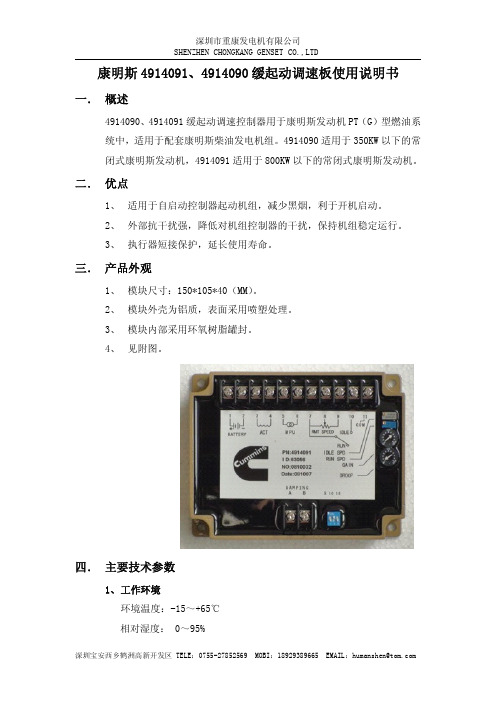
康明斯4914091、4914090缓起动调速板使用说明书一.概述4914090、4914091缓起动调速控制器用于康明斯发动机PT(G)型燃油系统中,适用于配套康明斯柴油发电机组。
4914090适用于350KW以下的常闭式康明斯发动机,4914091适用于800KW以下的常闭式康明斯发动机。
二.优点1、适用于自启动控制器起动机组,减少黑烟,利于开机启动。
2、外部抗干扰强,降低对机组控制器的干扰,保持机组稳定运行。
3、执行器短接保护,延长使用寿命。
三.产品外观1、模块尺寸:150*105*40(MM)。
2、模块外壳为铝质,表面采用喷塑处理。
3、模块内部采用环氧树脂罐封。
4、见附图。
四.主要技术参数1、工作环境环境温度:-15~+65℃相对湿度:0~95%振动:25HZ2mm2、工作电源工作电压:24±6V(DC)接地方式:负极接地(机体)最大使用电流: 2.5A24V绝缘强度100V:≥500M五.接线说明1脚:电源正极(DC24V+)输入2脚:电源负极(DC24V-)输入3、4脚:执行器(无正负)输出5脚:转速传感器正极输入6脚:转速传感器负极输入7、9脚:转速调整电位器的两端(无正负,阻值为5K¢)8脚:转速调整电位器的中心端(无正负,阻值为5K¢)7、10脚:怠速运行开关,断开全速运行,闭合怠速运行11脚:负极,可不接A、B脚:机组调试不稳定时可短接六.调整设定怠速电位器(IDLE SPD):怠速运行转速调整电位器,调整机组在怠速运行时的转速(600-800转/分),顺旋为升速,反旋为降速。
运行电位器(RUN SPD):全速运行转速调整电位器,调整机组在全速运行时的转速,顺旋为升速,反旋为降速。
增益电位器(GIAN SPD):调整机组在运行时的反应速度和稳定性,顺旋反应快,反旋稳定性好。
一般调整在5-7格处。
速度下垂电位器(DROOP SPD):调机组空载到全载之间的转速下降值(一般用于并机),顺时针方向调节DROOP会增加。
GAC电调说明书 康晨-康明斯定型2004319

GAC
ESD5500
C1 OF LEAD CIRCUIT F ON SPEED RAMPING
C2 OF F SOFTCOUPLING ON
E3 E2
GAIN
E1
SPEED STARTIN G FULE RAMPING
SPEED DROO P
C2剩余频率(软接合如双轴承发电 球)抑制线路。通常在“OFF”位, 如执行器因为软接合引致不正常摆 动,将开关打到“ON”。 当端子M及G连接上后,可调校怠 速的设定值 当端子K及L连接上后,可调校调速 率的下垂 速度调节为25转的电位器
- + ACTUATOR PICK-UP BATTERY
A B C D E F G H J K L M N P
IDL E
AUX
10V OUTPUT
P:10V的稳定电源,用于其它的GAC 模块 N:为同步器、负载分配、斜坡发生器等输入讯号点 执行器 速度传感 器 最低运行信号: 1.0AC 电瓶 OFF ON 8A保险丝 外接频率微调电位 器 G-M:怠速开关,接通之、可使发动机下降至怠速 K-L:接上可作调速率下垂整定。不并车 无需调整。 如电源为12V时,连接(G-H)输出端子
k
专业 技术资料
GAC电子调速器技术说明书
襄樊康晨机电工程有限公司技术部
资料名称: 襄樊康晨机电工程有限公司技术部
k
专业 技术资料
附图1 电路接线与调整
稳定调校为1转的电位器 增益调校为1转的电位器 微分时间补偿:如果发动机当增益 小时快速游车,请将跨接线(E1E2)剪断;如果发动机很慢的游车, 请将一只电容器焊接在E2(-)及 E3(+),电容器为15V10~20mfd。 C1超前/滞后电路开关,通常在 “ON”位,如果调速器性能良好, 但执行器快速跳动,将开关打到 “OFF”。
康明斯发电机操作手册中文
操作手册发电机组型号GGHG, GGHH配备PowerCommand® Control控制器PCC 2100英文版公告号:928-0144B 03-2004中文版公告号: 928-0144B-CH2005年8月中国北京翻译目录章节 标题页码 重要安全注意事项 (iii)1引言..............................................................................................................1-1概述...........................................................................................................................1-1如何获得服务.............................................................................................................1-1 2技术规格.......................................................................................................2-1 3控制功能.......................................................................................................3-1概述...........................................................................................................................3-1起动前检查................................................................................................................3-1控制面板电源开/关模式.............................................................................................3-2前面板........................................................................................................................3-4起动...........................................................................................................................3-6停机...........................................................................................................................3-7菜单显示和按键.......................................................................................................3-11主菜单......................................................................................................................3-13调整默认设置...........................................................................................................3-15系统消息..................................................................................................................3-15控制器设置菜单.......................................................................................................3-16发动机菜单..............................................................................................................3-18发电机菜单..............................................................................................................3-20调整菜单..................................................................................................................3-22故障菜单..................................................................................................................3-24系统菜单..................................................................................................................3-26历史菜单..................................................................................................................3-28关于菜单..................................................................................................................3-30电源切换菜单...........................................................................................................3-32警告此产品发动机所排出的废气含有加州政府认为可导致癌症、先天缺陷或其他生殖损害的化学物质。
康明斯发电机技术AGN 030 – 服务和维护说明书
Application Guidance Notes: Technical Information from Cummins Generator Technologies AGN 030 – Service and MaintenanceDESCRIPTIONSuitable service and maintenance are vital to the reliable operation of the alternator and the safety of anyone coming into contact with the alternator. The alternator should be inspected between scheduled maintenance, in line with inspection procedures and schedules provided by the manufacturer to identify any potential failure modes, signs of misuse or excessive wear and tear.An alternator specific Owner’s Manual (also known as Installation, Service and Maintenance Manual) is supplied with every alternator. The manuals are also published on the website. Each manual includes a Section on Service and Maintenance.The service activities are intended to maximise the life of the alternator but shall not vary, extend or change the terms of the manufacturer’s standard warranty or the customer’s obligation in that warranty.Each service interval is a guide only, developed on the basis that the alternator was installed and is operated in accordance with the manufacturer’s guidelines. If the alternator is located and/or operated in adverse or unusual environmental conditions, the service intervals may need to be more frequent. The alternator should be continually monitored between services to identify any potential failure modes, signs of misuse or excessive wear and tear. Recommended Service ScheduleThe recommended service schedule published in the manual shows the recommended service activities in table rows, grouped by alternator subsystem. Columns of the table show the typesof service activity, whether the alternator must be running, and the service levels. Service frequency is given in running hours or interval time, whichever is sooner. A cross (X) in the cells where a row intersects the column shows a service activity type and when it is required. An asterisk (*) shows a service activity done only when necessary.Service level documents referred to in the recommended service schedules can be purchased directly from Cummins Generator Technologies Customer Service Department, by telephone on +44 1780 484732 or by email: **************************************************. STAMFORD AlternatorsThe recommended service schedule for STAMFORD alternators can be found in Section 7 of the manual, with the following breakdown of sub-sections:Recommended Service ScheduleBearingsControlsCooling SystemCouplingRectifier SystemTemperature SensorsWindings.AvK AlternatorsThe recommended service schedule for AvK alternators can be found in Section 10 of the manual, with the following breakdown of sub-sections:Preventive ServicingSafety PrecautionsRecommended Service ScheduleServicing – General StructureVibrationServicing the Bearings and the Lubrication SystemGenerators with Bearing InsulationService WindingsServicing the Generators CoolerRepairs, Dismantling and Reassembly.Importance of Alternator MaintenanceThe maintenance programme is developed to meet the needs of different alternator designs. There are three types of maintenance strategies;∙Reactive maintenanceo Failure or abnormal operation.∙Preventive time based maintenanceo Time based maintenance.o Based on manufacturer’s experience.Predictive / condition based maintenanceo Maintenance based on actual measurements.A regular preventive maintenance schedule will ensure peak performance, maximize alternator life, maximized reliability and minimize breakdowns.INSTALLATION CONSIDERATIONSThe alternator must be installed in an accessible location with easy access to the main terminal box, bearing cap, air filter, louvers (inlet and outlet) and NDE/DE end brackets. The mentioned access points provide easy access to internal alternator components as shown in Figure 1. This will allow the execution of periodic inspections, local maintenance and removal of the alternator for external services.Figure 1: Internal alternator components that require periodic maintenance. Alternators LiftingDifferent alternator designs must be lifted by hooks or shackles attached to the lifting points (lugs or eyes). Chains of sufficient length, and a spreader bar if necessary must be used when lifting the alternators so as not to damage the terminal box, alternator parts and prevent the rotor from failing out on 1 bearing alternators as shown in Figure 2. When lifting entire Generating Set, the installation engineer must use specially designed Generating Set lifting points, and not alternator lifting lugs.Figure 2: Showing an example of the right and wrong alternator lifting methods. Mechanical CouplingInstallation engineers should follow the alternator manufacturer’s integration instructions provided in the Owner’s Manual. When coupling, the engineer should not attempt to rotate the alternator rotor by levering against the vanes of the cooling fan as shown in Figure 3 as the fan is not designed to withstand such forces and will be damaged. The holes of the coupling discs should be aligned with the flywheel holes by cranking the engine. Additional forces should not be put on the bearings while assembling the coupling half as it will damage the bearings.Figure 3: Alternator cooling fan vanes.SafetyIt is important to follow the alternator manufacturer’s general and local health and safety instructions. Incorrect installation, service or replacement of parts can result in severe equipment damage and personal injury. Only qualified individuals should perform electrical and mechanical component installations. Safety information signs are provided on the equipment to indicate hazards and emphasize instructions.Figure 4: Examples of the safety signs provided on an alternator. Environmental ConditionsAlternators installed in Generating Sets that are sited in arduous ambient environmental conditions may be susceptible to breakdown at their location site, if appropriate service and maintenance is not carried out. Ensuring reliable satisfactory service though, starts with careful consideration being given to the design of the ventilation systems that will be shared by both alternator and engine. Simplifying the considerations to just deciding to have a relatively simple canopy with large openings for the benefit of the engine and then considering the alternator satisfied by the fitting of low cost air filters will result in operating problems.Decisions at the Generating Set design stage about the Canopy design and airflow control must include discussions with the alternator manufacturer to ensure that the appropriate optional extra air-filter / louver kit is nominated or the IP rating of the alternator is increased and that a bespoke maintenance regime is implemented for the complete Generating Set.Refer to AGN072 – Environmental Conditions, for guidance on appropriate installation from the alternator manufacturer’s viewpoint.Alternators in Coastal LocationsFor example; an RTG Crane application is a quite unique situation. For reasons of making the alternator output characteristics suitable to power the Crane’s drive motor, combined with the duty cycle of the variable crane motor load, the alternator is usually operating with quite low winding temperatures. Whilst this low temperature situation would normally be considered to be beneficial, it does introduce a problem when the operating environment is a salt laden with a high humidity. The accepted winding temperature at which moisture is driven from the windings is some 95o C and experience is showing that RTG applications do not achieve this. So we have a winding contaminated by a salt laden atmosphere, combined with the dust and pollutants around a working dockside, plus RIC engined port vehicles adding exhaust by-products to this winding contamination problem. Add to this the humidity and moisture associated with local weather conditions, forming surface moisture on the alternator’s outhang, a winding that is not getting hot enough to drive the moisture off and we have created a winding insulation system with much reduced ‘barrier’ capabilities.The above considers the contaminants that weaken the winding insulation system. The following explains the additional electrical stresses associated with the Variable Speed Drive units used to power the various crane movements.These VSD’s are Non Linear Loads [NLL], with quite high levels of harmonic distortion. The resulting harmonic voltage distortion results in transient voltage conditions that may well be twice the peak value that the alternator would experience under normal linear load conditions.These high transient voltage spikes stress the electrical insulation system, with which a clean uncontaminated winding insulation system can cope. But a contaminated winding will find such transient voltage spikes difficult to contain, followed inevitable by the breakdown of the insulation barrier and winding short circuit.The decision to have the new alternator fitted with IP44 inlet louvers will ensure that whilst the alternator is running, the inlet cooling air is being filtered and moisture droplets are being removed by the Premaberg filter system.However the IP44 filter assembly is not really addressing all the problems of the location being in a coastal, salt laden atmosphere. The problem with salt is that it will form a moisture absorbing film of contamination on the alternator’s winding. When the alternator is working and the windings are hot, the moisture is driven off the windings surface and the insulation resistance - IR - will be high enough to ensure that no insulation breakdown or surface tracking occurs. However; as soon as the Generating Set is stopped, the alternator’s local environment becomes extremely humid, it is at this point the hygroscopic layer of salt that has formed on the windings will absorb moisture and this will result in the windings IR value being reduced to a low level and so, an inability to insulate/isolate phase to phase and phase to earth. Therefore, when the Generating Set is next started and the alternator excites to the normal working voltage - electrical pressure - there is a real risk that an insulation failure will occur as a result of insulation breakdown initiated by surface tracking.The ideal solution is to filter the salt from Generating Set cooling air. But the practicalities must include control of the humidity level of the alternator’s environment and this involves far more than the fitting of an alternator anti-condensation heater.The most successful schemes involve a fan heater bl owing several kW’s of hot air around the Generating Set ‘chamber’ to keep the humidity RH% as low as possible. Obviously, this needs an electrical power supply when the Generating Set is not running and so may well not be an easy option.There may be a way of running-on the Generating Set after its programmed service duty. This would be in a way devised to keep hot dry air circulating whilst the whole Generating Set area temperature is gradually reduced to stop the sudden increase in RH% that occurs around Generating S ets when they are stopped and left trapped in their ‘sweat box’ canopies.It could be that Generating Set’s are operating in parallel, or a Generating Set is operating in parallel with a mains supply. This then suggests an option to introduce some Generating Set environment control, because it would seem that there is always an electrical supply available. We cannot rule out that the stresses associated with miss-paralleling, or the instability of the local mains supply e.g.; micro-interruptions, will damage insulation systems and promote failures. But if the site history is one of winding failures occurring at the point/moment of starting the Generating Set ready to put the unit back into service then, from experience, we would consider saline contamination is the prime culprit.MAINTENANCE OF THE WINDING INSULATION SYSTEMThe only way to check on the condition of the winding insulation system, is by introducing a regular procedure to check the stator winding Insulation Resistance (IR) value and although not normal practice for a low voltage scheme, the Polarisation Index [PI] should be measured too, if the alternator is installed in any challenging environment. This check of IR and PI need only be carried out to the stator winding. The spinning of the rotor and the fact that it operates at low voltages means that it is not, as much, at risk.Refer to AGN015 – Testing Winding Insulation Systems for details of IR and PI testing.At the first sign that the IR and PI are low, the alternator stator winding must be cleaned.T he exciter field is another ‘at risk’ component and the fact that it operates with dc. means that it has a high risk factor due to its operation with fixed polarisation. If the exciter field insulation fails it will also take out the AVR.Cleaning windingsIf cleaning of the windings becomes necessary, then the preferred method is to completely strip the alternator to enable a thorough inspection and then a washing process, which will result in dirt removal by encouraging a washing-out of dirt by an action that will not result in the dirt being forced further into the winding assembly. The washing medium should be clean hot water applied from a directional nozzle at a pressure not exceeding 3bar.At no point should the winding insulation be subjected to a jet of water pressure that is deforming the insulation materials.For extremely oily contaminants, an alternative method is to use a hot pressure wash - not exceeding 3bar – with an added solvent based biodegradable cleaner of neutral pH. Note: ‘Autosmart’ and Aquawash’ are trade names of such biodegradable cleaners.Water-based Alkaline Detergents should not be used for cleaning as they contain ‘wetting agents’ that leave contaminants - in the form of salts - on the winding surfaces. These contaminants are hygroscopic and therefore readily absorb moisture, which will lower the insulation resistance and promote surface tracking.Caution: Inappropriate or badly executed cleaning methods will leave contamination embedded in the winding crevices and this local contamination will promote degradation of the insulation system.After the cleaning process, the windings must be slowly[over several hours] heated to at least 100degC in a thorough drying out procedure of perhaps twelve to twenty four hours. The insulation resistance [IR], phase to phase, and phase to earth, must be measured during this process.Refer to the alternator’s Owner’s Manual (Installation, Service & Maintenance Manual) for the drying out procedures and the IR test procedure, including the values, in Mega-Ohms, that thewinding must achieve before the winding IR can be said to be high enough for the wound assembly to be considered a serviceable unit.Once the windings have been cleaned and the insulation resistance improved to what is considered to be a satisfactory level, the clean and dry windings should be treated with an appropriate ‘over-coating’ electrical anti-tracking resin / varnish. This treatment will offer protection from further immediate in-service recontamination of the winding surface. The chosen anti-tracking material should be of the same insulation thermal rating as the alternator’s insulation system - Class ‘F’ or Class ‘H’.Checks must also be made to ensure that the electrical anti-tracking resin / varnish will adhere to the windings original impregnation materials.Application Guidance Notes are for information purposes only. Cummins Generator Technologies reserves the right to change the contents of Application Guidance Notes without notice and shall not be held responsible for any subsequent claims in relation to the content.。
(6BT5.9-G2)75KW康明斯发电机组参数价格及操作说明
(6BT5.9-G2)75KW康明斯发电机组参数价格及操作说明GF-75KW发电机组功能及描述:带自启动控制系统/75KW康明斯发电机组销售。
(华中宏泰机电制造)康明斯OEM组装生产厂家。
低油耗75KW东风康明斯发电机组出售。
东风康明斯6BT5.9-G2发电机组油耗205g/kw.h;涡轮增压型;电子调速;最大功率达到92KW。
厂家机组按照配置定价!康明斯(重庆/东风系列)柴油发电机组安装出售。
知名品牌,质量超高,销量名列前茅。
功率覆盖20-1200KW。
具体价格来电咨询,根据配置而定。
选配有:自启动,自动化,水加热器,独立油箱,移动转盘,防雨罩,低噪音箱,移动低噪音箱,移动防雨罩等。
详情致137-****3128周远亮(华中宏泰机电),价格根据配置而定。
业务辐射地区:北京,天津,河北,湖北,上海,江苏,浙江,安徽等。
发电机组操作说明1.检查水位、油位。
2.检查电瓶线和其它线路是否松动。
3.检查柴油管路。
4.启动方式:1.先用手动启动发电机把开关拨至手动位置,然后用点火开关启动发电机,低速运行几分钟后再高速运行,等机组运行正常后开始合闸。
停机先拉闸,拨至低速运行,几分钟后再关闭点火开关,即停机。
2.把开关拨至模块,然后打开点火开关,按模块上手动模式再按启动按钮,即可以启动,停机只需按下停机按钮即可。
5.如遇紧急情况可用急停按钮。
6.检查显示屏上的电压、频率、转速、水温、油压、充电电流等情况。
7.80小时左右开始首保,更换机油、三滤,机油可参照柴油机公司说明书上指定品牌机油。
8.新机必须检查水路、气路的卡箍和底脚螺栓。
9.特别注意:发电机运行期间必须有专门人员看管。
康明斯柴油机KCM-IIG(A)说明书图纸资料

②低油压报警 n>350r/min 后生效。 5. 停车
① 正常停车操作只需要将电源开关拨至“关”的位置即可。 ② 非正常停车只要迅速按下“紧急停车”按钮和开关即可(如果安装此按钮,事
3
CCEC
● 警示: 仪表箱电气测控系统按船规要求为双线制,即所有电气零部件都必须有
二个以上的接线头。不能采用或更换以壳体搭铁作为负极的单接线电 器,例:马达、充电机、燃油阀等! 仪表箱内从主电源开关至各测量控制板之间均设置有过电流保险器,他 们的容量只能保证自己正常工作,所以不允许外加改装的设备从箱中取 24V 电源,否则会造成仪表工作不正常或损坏! 报警外接延伸板仅有下端 28 个端子供用户外接,其他端子是仪表内接或 远程表用的端子,不允许改接线路它用!
注:仪表的测量精度优于 2.5 级(数字表优于 0.5 级)。 2. 控制开关配置
① 电源开关—用于控制仪表箱电源的通断和正常停车。 ② 仪表主/备电源切换开关—当仪表有主/备二组电源接入时,用它进行转换。 ③ 本机/远起动选择开关—选择在机上起动或远端起动柴油机。 ④ 正常运行/越控运行选择开关—在紧急情况下把此开关拨至“越控”位置时,报
调至 50%、DROOP 调至 1-2 格间(3%Ne)。 ⑤ IDLE(怠速)和 RUN(运行)转速调整电位计均是多圈无限位的,注意要边调边
看,否则难以复位。
五、 继电器报警延伸输出接口及控制连接板
此板提供以下输出口供用户选用(参见附图) ① 远程监测仪表接口端子 8 个,用于连接 KCM-IIGR 远程仪表箱。 ② 连接 PC 计算机的 RS485 接口端子 2 个(需配用 RS485/232 转换器接至计算机,通
康明斯KTA系统说明书(1)汇总

第3章电路板和模块概述本章叙述有关PCC控制盘和附件箱内的电路板与模块的功能(图3-1),图3-2方框图显示了PCC系统的内部和外部部件。
本手册第9章给出了系统原理图。
静电放电将损坏电路板,当接触电路板或接插晶片时,请预先戴好手腕型接地环带。
图3-1.电路板位置3-1图3-2. 方框图3-2数字电路板(A32)数字电路板(图3-3)包含控制盘用微处理器和操作软件,同时数字电路板还连接到控制盘内其它电路板。
数字电路板也为PCC提供模拟信号与数字信号之间的转换。
开关S5 将开关推向左侧为接电模式,此时控制盘电源/操作软件一直通电,直到开关扳到备用模式。
建议在所有应用中始终将S5开关设在接电模式位置,除非不能提供辅助蓄电池充电。
向右推动此开关将PCC切换到备用模式。
在此模式,PCC操作软件将会因:(1)前端面板操作开关置于运行(Run)位置,(2)按自我侦测键,(3)遥控起动输入信号(前端面板开关位于自动位置)或接到外来开关的任一“唤醒”信号而被初始化。
接插件数字电路板上有5个接插件,说明如下:J1 串行界面RS232。
J2 连接到用户界面电路板(A34)上的J4。
J3 连接到模拟电路板(A33)上的J2。
J4 连接到发动机界面电路板(A31)上的J1。
J5 连接到数字显示电路板总成(A35)上的J5。
二极管(LED)数字电路板共有7组二极管,分别显示下列状态:DS1 备用(绿色)。
DS2 备用(绿色)。
DS3 直流+18伏特电源正常(绿色)。
DS4 直流+5伏特电源正常(绿色)。
DS5 运行(如果软件正在工作,它将每秒闪烁一次)(绿色)。
DS6 直流+24伏特B+电源正常(绿色)。
直流+12伏特电源正常(绿色)。
图3-3. 数字电路板3-3发动机界面电路板(A31)发动机界面电路板(图3-4)可读出操作者的控制输入信号,监测发动机、发电机和系统的状态,并针对正常操作和故障状态(报警或报警停机)作出正确反应。
中文-原厂康明斯电力(PCC3201)操作手册
加利福尼亚州 65号警告
加利福尼亚州认定,柴油发动机废气以及其中的一些成分可以导致 癌症、先天缺陷以及其它生殖系统损害。
i
严禁以任何形式出版和发行本手册
章节
4 5
6
标题
页码
概述………………………..………………………………………………...……………………4-1
安全注意事项………………………..………………………………………………...………4-1 状态指示灯………………………..………………………………………………...…………4-1 阅读故障代码………………………..………………………………………………...…………4-2 断路器(选装件)………………………..…………………………………………………4-2 通过网络或个人计算机(便携式)进行控制及诊断………………………..……………4-2 故障代码………………………..………………………………………………...………………4-4 故障代码表………………………..………………………………………………...……………4-5 故障检测表………………………..………………………………………………...……………4-8
一般安全保障措施
z 高压下的冷却液,其沸点比水的沸点还高。 发
动机运行时,不要打开加热器或热交换器的压
力盖。 应当首先让发电机组逐渐冷却,从而使
系统的压力得以释放。
z 美国的一些州和联邦政府已确定:用过的机油
可能会致癌或带来生殖系统损害。检查或更换
机油时,应加以小心,防止吸入油雾或接触到
废机油。
z 确保机组区域通风良好。 z 加利福尼亚州认定,柴油发动机废气及其其中的
一些成分可以导致癌症、先天缺陷以及其它生殖 系统损害。
康明斯电调说明书

目录序-------------------------------------2 功能介绍----------------------------3 安装说明----------------------------8 故障处理---------------------------11序电子调速系统是发动机速度调节系统,其主要任务是:保持发动机转速在设定转速运转。
机械调速和电子调速的不同之处在于:电子调速能够通过控制单元(1·Fig.1.)来“感受”实际转速与设定转速的不同,将此差值变换传给执行单元(执行器)来调节燃油流量从而增加或降低发动机转速转速,使之保持在设定转速运行。
Fig.1. 电子调速系统结构1、控制单元(调速板)4、停车阀/燃油阀2、发动机速度传感器5、电池3、执行器功能介绍发动机转速传感器发动机转速传感器安装于发动机飞轮壳上方正对飞轮,当飞轮齿经过转速传感器,传感器就产生一交流电信号(每一齿产生一个脉冲信号)。
脉冲电压在1V AC~30V AC之间转速传感器的安装螺纹是5/8”-18 UNF-2A Fig.2. 传感器部分1、转速传感器2、飞轮齿控制器(调速板)电子控制器(调速板)的基本功能是:比较输入转速信号与设定值,然后将校正或不变的指令传输给执行器。
调速板有以下调节功能,只须将黑色圆胶盖打开即可进行调节:1、调节怠速转速“IDLE”,把端子“G”和“M”短接,调节电位器(4·Fig.3.),调节频率范围在1200-4100HZ之间,顺时针调节电位器将增加怠速转速。
2、运行速度调节“SPEED”,频率调节范围在100-6000HZ,顺时针调节将增加发动机转速。
上面的调节频率来自电磁传感器(转速传感器),频率值取决于发动机飞轮齿数和发动机转速。
即:频率值=发动机转速(r/s)×发动机飞轮齿数例:CUMMINS NTA855-G1发动机齿数是118,转速在1500r/min(25r/s):25×118=2950HZ.Fig.3.调速板ESD55001、运行速度调节、设定 5、下垂调节2、增益调节、设定 6、启动燃油调节3、稳定性控制 7、转速坡度调节4、怠速调节注:不同型号调速板各电位器排列位置略有不同,请以标识为准3、增益调节“GAIN”,转速的灵敏度是通过调节“GAIN”电位器(2·Fig.3.)实现的,顺时针调节将使灵敏度增加;——顺时针调节“GAIN”电位器,直到发动机出现抖动,再旋回1/8圈;——当调整灵敏度时频率可能会有很小的变化,这个变化可通过调整“SPEED”电位器来调整。
康明斯柴油发动机电子调速器及控制系统故障

康明斯柴油发动机电子调速器及控制系统故障康明斯柴油发动机PT(G)型燃油系统中,使用EFC电子调速器。
调速器可以调成同步运行或调成有转速降的运行。
本文介绍的是发电机组或驱动发动机上的康明斯电子调速器EFC的原理、调整和故障诊断技术,对用户准确、快速地排除该类机型的故障具有重要作用。
1 工作原理该机自动化程度高,控制比较复杂。
调速器控制电路如图1所示。
电磁转速传感器3装在飞轮壳上。
通过飞轮齿圈感应发动机的转速。
执行器2装在PT泵内,改变执行器电流将使执行器的轴转动,从而改变发动机的转速和功率。
当CPU板J5第7脚的运行开关RUN闭合时,J1的1脚输出24V电压,PT泵电磁阀开关SWITCHED得电开启,EFC调速控制器4得电工作,使控制器2的轴转到最大供油位置。
同时,CPU板J1的第3脚输出起动信号到启动马达,使发动机启动。
发动机启动后,交流发电机的中点(N)电压(约12V)作为发动机已启动的信号,通过J2的第3脚输入CPU控制板,从而切断J1第3脚输出的信号,使启动机停止工作。
若一次启动不成功,停10s后将自动再次启动,若连续三次启动不成功,则停止启动,故障灯点亮。
发动机正常工作后,发动机的各种参数通过J3插座输入CPU板,由J4输出各种报警灯信号。
按J5的复位/灯检查按钮,可使CPU复位,同时进行各种报警灯测试,若所有报警灯都亮,说明整个报警控制系统工作正常。
发动机启动以后,EFC调速器4把来自电磁传感器的电讯号与现有的参考点(W2)相比较,输出差压电流信号,使执行器2的轴转动,控制进入喷嘴的燃油流量,从而改变发动机的转速和功率。
当发动机在W2调定的某一转速下稳定工作时,调速过程如下:负载↑↓→(转速传感器3)发动机转速↓↑→EFC调速器4输出电流↑↓→执行器2供油量↑↓→发动机转速↓↑→使发动机转速稳定在某一定值工作。
1.CPU控制板2.EFC油门执行器3.电磁转速传感器4.EFC电子调速器W1.怠速调整电位器W2.运行转速调整电位器W3.增益调整电位器W4.转速降调整电位器,J2-3.交流发电机中点电压(N)输入J2-7.机油压力传感器输入J2-8.水温传感器输入J3-2.油压低传感器输入J3-3.水温高预警传感器输入J3-4.油压低预警传感器输入J3-5.水温高传感器输入J4-12.油压低预警灯输出J4-11.水温高预警灯输出J4-10.油压低报警灯输出J4-9 水温高报警灯输出J4-8.超速报警灯输出J5-11.复位/灯检查按钮输入J5-7.运行按钮输入J5-4.接机油压力表J5-3.接水温表图1 控制电路原理图2 系统调整EFC调速控制器的面板上装有四个电位器,W1为怠速调整电位器(IDLE SPD),W2为运行转速调整电位器(RUN SPD),W3为增益调整电位器(GAIN),W4为转速降调整电位器(DROOP),这些电位器供系统调整时用。
东风康明斯100KW发电机组技术参数说明书
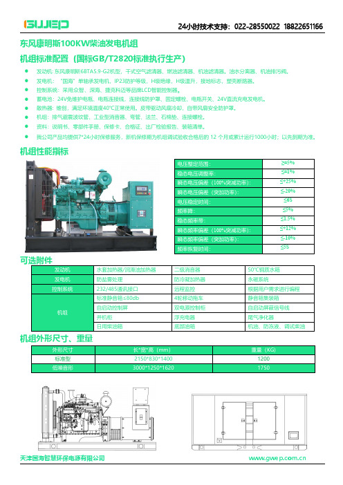
东风康明斯100KW柴油发电机组
机组标准配置(国标GB/T2820标准执行生产)
●发动机:东风康明斯6BTA5.9-G2机型,干式空气滤清器、燃油滤清器、机油滤清器。
油水分离器、机油排污阀。
●发电机:“国海”单轴承发电机,IP23防护等级,H级绝缘,H级温升,接地标志,塑壳断路器。
●控制系统:采用众智、深海、捷克科迈等品牌LCD智能控制器。
●蓄电池:24V免维护电瓶、电瓶连接线,连接线防护罩、固定螺栓、电瓶开关、24V直流充电发电机。
●散热器:维创,满足环境温度40℃正常使用。
皮带驱动风扇冷却,自带风扇安全防护罩。
●机组:排气避震波纹管、工业型消音器、弯管、法兰、石棉垫、连接螺栓。
●资料:说明书、零部件手册、保修卡、合格证、出厂检验报告、装箱清单。
●
我公司产品均提供7*24小时保修服务,新机保修期为机组调试验收合格后的12个月或累计运行1000小时;以先到期为准。
机组性能指标
机组外形尺寸、重量
东风康明斯100KW发电机组技术参数。
康明斯KTA系统说明书(1)汇总
第3章电路板和模块概述本章叙述有关PCC控制盘和附件箱内的电路板与模块的功能(图3-1),图3-2方框图显示了PCC系统的内部和外部部件。
本手册第9章给出了系统原理图。
静电放电将损坏电路板,当接触电路板或接插晶片时,请预先戴好手腕型接地环带。
图3-1.电路板位置3-1图3-2. 方框图3-2数字电路板(A32)数字电路板(图3-3)包含控制盘用微处理器和操作软件,同时数字电路板还连接到控制盘内其它电路板。
数字电路板也为PCC提供模拟信号与数字信号之间的转换。
开关S5 将开关推向左侧为接电模式,此时控制盘电源/操作软件一直通电,直到开关扳到备用模式。
建议在所有应用中始终将S5开关设在接电模式位置,除非不能提供辅助蓄电池充电。
向右推动此开关将PCC切换到备用模式。
在此模式,PCC操作软件将会因:(1)前端面板操作开关置于运行(Run)位置,(2)按自我侦测键,(3)遥控起动输入信号(前端面板开关位于自动位置)或接到外来开关的任一“唤醒”信号而被初始化。
接插件数字电路板上有5个接插件,说明如下:J1 串行界面RS232。
J2 连接到用户界面电路板(A34)上的J4。
J3 连接到模拟电路板(A33)上的J2。
J4 连接到发动机界面电路板(A31)上的J1。
J5 连接到数字显示电路板总成(A35)上的J5。
二极管(LED)数字电路板共有7组二极管,分别显示下列状态:DS1 备用(绿色)。
DS2 备用(绿色)。
DS3 直流+18伏特电源正常(绿色)。
DS4 直流+5伏特电源正常(绿色)。
DS5 运行(如果软件正在工作,它将每秒闪烁一次)(绿色)。
DS6 直流+24伏特B+电源正常(绿色)。
直流+12伏特电源正常(绿色)。
图3-3. 数字电路板3-3发动机界面电路板(A31)发动机界面电路板(图3-4)可读出操作者的控制输入信号,监测发动机、发电机和系统的状态,并针对正常操作和故障状态(报警或报警停机)作出正确反应。
康明斯电子调速器资料
电子控制器
高怠速调整电位器
– 在仪表箱内 – 可转20圈的电位器
– 调整空载转速 – 顺时针转,增大空载转速
康明斯仪表板
怠速和运行开关
– – – – 在仪表板上 选择怠速或运行状态 扳上为运行 扳下为怠速
康明斯仪表板
转速微调电位器
– 在仪表板上 – 可转10圈的电位器 – 用于空载转速、增益 和速度降调整好后速 度微调。 – 调整前松开锁紧螺母, 调整后拧紧锁紧螺母。
康明斯电子燃油调速器
由三部分构成:
– 执行器 – 转速传感器 – 电子控制器
调速器确定发电 机组的性能。
康明斯电子燃油调速器
康明斯电子燃油调速器
执行器
– 常开式 – 常闭式
康明斯电子燃油调速器
执行器
– 低流量 – 高流量 – 特高流量
康明斯电子燃油调速器
转速传感器安装
– 传感器与齿顶间隙 0.71-1.07mm – 传感器旋入顶到齿顶 后退回0.50-0.75圈
转速降初调整
– 反时针转到底为同 步运行0%转速降 – 放在40处,大约为 3%转速降 – 放在80处,大约为 5%转速降
电子燃油调速器调试
怠速-运行开关放在 怠速位置
– 当发动机在怠速运行时, 电路主开关断路。电子燃油调速器调试
怠速调整
– 启动发动机 – 调整怠速电位器使 转速到达600-650 r/min
康明斯电子燃油调速器
转速传感器安装
– 当发动机转速达到 186r/min以上传感 器电压低于1.5VAC, 可将传感器再旋入 0.13-0.25圈
康明斯电子燃油调速器
电子控制器
- 仪表箱内安装式 - 远程安装式
山东康明斯发电机GU621A使用说明
操作
注意: z 三种操作模式只能任选其一。 z 操作模式转换时,控制器先保持之前模式的全部控制状态,再根据当时状况,
执行新模式的控制程序。
4.2 自动控制过程
控制器运行于自动操作模式。
市电正常,市电供电: 当市电正常时,即市电电压和频率在设置的高低极值范围内,市电正常指示灯亮,市电供电延时计
市电合闸失败:如市电合闸继电器闭合输出,市电开关合闸时间计时器开始计时,计时时间到,控 制器没有检测到市电侧开关辅助触点闭合,即为市电合闸失败。
10
GU621A 控制器使用说明
注意: z 以上控制程序的实现,是将其中一个可定义输入口定义为市电开关闭合,并将开
关的常开辅助触点连接到该端口。 z 实际应用中,可能没有一个可定义输入口定义为市电开关闭合,此时,市电合闸
名称
消声键/灯测试 当控制器发生警告或故障时,报警蜂鸣器响,按此键响声停止;再按此键, 则取消消声功能,如控制器仍处在故障状态,报警蜂鸣器继续响。消声功能 有效时,LCD 显示消声符号。 连续按此键 2 秒,所有指示灯同时亮。 自动模式键/指示灯/参数设置增加“+”键 此键用于自动操作模式设置,控制器运行于自动模式时,键上侧 LED 指示灯 亮。控制器根据市电故障且“遥开信号”有效与否,来控制发电机启动运行 与停止。 当进入参数设置操作,此键用于增加数值/向下移动选择。
开启键/指示灯/参数设置向上键 此按键用于手动启动运行发电机组。当控制器设置在手动操作模式时,按此 键可启动发电机。 当进入参数设置操作,此键用于返回上一层菜单。
停机/复位键/指示灯/参数设置位移“→”键 此按键用于手动停止发电机,控制器设置在手动操作模式时,长按此键两秒 以上,可停止发电机组。 如果有故障输出,轻按此键控制器可解除故障停机锁定。 当进入参数设置操作,此键用于移动参数的可设置位。 不管控制器运行于何种模式,“停机键”均有效。在“自动”或“测试”模 式时,长按此键两秒以上,可停止发电机组,控制器同时自动从其它模式转 换为手动操作模式。
康明斯发电机操作规程

康明斯发电机操作规程
《康明斯发电机操作规程》
一、操作人员应经过专业培训,了解发电机的结构、原理及操作程序。
二、在操作发电机之前,要仔细检查设备的各项指标,确保设备正常运转。
三、启动发电机时,要按照操作手册上的程序进行操作,注意检查机器是否正常启动,是否有异常声音或异味。
四、发电机运转期间,操作人员应时刻监控设备的工作状态,保持设备平稳运行。
五、发电机停止运转时,应按照操作手册上的程序进行操作,确保机器平稳停止。
六、定期对发电机进行检查和保养,保持设备的良好状态。
七、在发现设备异常时,及时停止运行,并进行维修或更换零部件。
八、禁止在操作发电机时进行任何违反安全规定的行为,确保操作人员和周围环境的安全。
以上是关于康明斯发电机的操作规程,希望每一位操作人员都能严格按照规程进行操作,确保设备的安全运行。
- 1、下载文档前请自行甄别文档内容的完整性,平台不提供额外的编辑、内容补充、找答案等附加服务。
- 2、"仅部分预览"的文档,不可在线预览部分如存在完整性等问题,可反馈申请退款(可完整预览的文档不适用该条件!)。
- 3、如文档侵犯您的权益,请联系客服反馈,我们会尽快为您处理(人工客服工作时间:9:00-18:30)。
目录序-------------------------------------2 功能介绍----------------------------3 安装说明----------------------------8 故障处理---------------------------11序电子调速系统是发动机速度调节系统,其主要任务是:保持发动机转速在设定转速运转。
机械调速和电子调速的不同之处在于:电子调速能够通过控制单元(1·Fig.1.)来“感受”实际转速与设定转速的不同,将此差值变换传给执行单元(执行器)来调节燃油流量从而增加或降低发动机转速转速,使之保持在设定转速运行。
Fig.1. 电子调速系统结构1、控制单元(调速板)4、停车阀/燃油阀2、发动机速度传感器5、电池3、执行器功能介绍发动机转速传感器发动机转速传感器安装于发动机飞轮壳上方正对飞轮,当飞轮齿经过转速传感器,传感器就产生一交流电信号(每一齿产生一个脉冲信号)。
脉冲电压在1V AC~30V AC之间转速传感器的安装螺纹是5/8”-18 UNF-2A Fig.2. 传感器部分1、转速传感器2、飞轮齿控制器(调速板)电子控制器(调速板)的基本功能是:比较输入转速信号与设定值,然后将校正或不变的指令传输给执行器。
调速板有以下调节功能,只须将黑色圆胶盖打开即可进行调节:1、调节怠速转速“IDLE”,把端子“G”和“M”短接,调节电位器(4·Fig.3.),调节频率范围在1200-4100HZ之间,顺时针调节电位器将增加怠速转速。
2、运行速度调节“SPEED”,频率调节范围在100-6000HZ,顺时针调节将增加发动机转速。
上面的调节频率来自电磁传感器(转速传感器),频率值取决于发动机飞轮齿数和发动机转速。
即:频率值=发动机转速(r/s)×发动机飞轮齿数例:CUMMINS NTA855-G1发动机齿数是118,转速在1500r/min(25r/s):25×118=2950HZ.Fig.3.调速板ESD55001、运行速度调节、设定 5、下垂调节2、增益调节、设定 6、启动燃油调节3、稳定性控制 7、转速坡度调节4、怠速调节注:不同型号调速板各电位器排列位置略有不同,请以标识为准3、增益调节“GAIN”,转速的灵敏度是通过调节“GAIN”电位器(2·Fig.3.)实现的,顺时针调节将使灵敏度增加;——顺时针调节“GAIN”电位器,直到发动机出现抖动,再旋回1/8圈;——当调整灵敏度时频率可能会有很小的变化,这个变化可通过调整“SPEED”电位器来调整。
4、稳定性控制“STABILITY”,速度调节时间常数是通过调节“STABILITY”电位器实现的。
时间常数即负载发生变化后恢复到发动机额定转速所需要的时间。
——顺时针调节“STABILITY”会缩短负载变化后系统的恢复时间;逆时针调节则使恢复时间加长。
5、转速降操作“DROOP”,顺时针旋转“DROOP”(转速降)调节器,转速降值将增加,当处于降落状态时,发动机速度将随负载的增加而降低;短接“G”和“H”可提高转速。
6、启动燃油调节“STARTING FUEL”,顺时针调节“STARTING FUEL”电位器,发动机启动过程中的燃油流量将增大,顺时针调节至最大,启动过程中的燃油将不受限制,执行器动作至最大;逆时针调至最小,启动过程中燃油将非常小或为零。
7、速度缓冲调节“SPEED RAMPING”,顺时针调节“SPEED RAMPING”电位器,发动机转速加速度减慢,加速时间最长可调到20秒。
ESD5500系列调速板ESD5500系列调速板包含ESD5100系列调速板的所有特性,另外,ESD5500系列还具有发动机燃油供给控制,从而消除过量燃油,降低了排烟浓度,提高了环保效益。
ESD5500系列与ESD5100系列的一点区别是:怠速选择开关的连接端子,ESD5500系列是“M”和“G”,ESD5100系列是“M”和“L”。
Fig.4. ESD5500调速板调速板的调整按如下方法对调速板进行预设:--STARTING FUEL 顺时针调最大(最大燃油)--SPEED RAMPING 逆时针调最小(最快启动)1、启动发动机并调节“SPEED”、“GAIN”、“STABILITY”,此时燃油供给将不受限制。
2、连接端子“M”和“G”,将发动机置于怠速运行状态。
3、调节怠速转速至略高于低转速报警设定值,保证低转速不动作。
4、逆时针调节“STARTING FUEL”直至发动机转速开始下降,然后顺时针微调“STARTING FUEL”使怠速转速恢复至要求值。
5、停机ESD5500系列调速板可选择以下两种运行方式之一:方式一:启动机组并直接加速至运行速度(发电机组等)断开端子“M”与“G“间的连接。
启动发动机并调节从怠速到额定速度的“SPEED RAMPING”(速度斜率),以获得最少排烟量。
若启动排烟过量,则需逆时针微调“STARTING FUEL”(启动燃油)。
若起动时间过长,则需顺时针微调“STARTING FUEL”(启动燃料)。
方式二:启动发动机并在怠速状态下运行一段时间后加速至运行速度此种方式将启动过程从加速过程中分裂出来,以更好地优化排放,使排放达到最低。
用一个开关替代端子“M”和“G”间的连接,通常用一个油压开关。
启动发动机,若启动排烟过量,则需逆时针微调“STARTING FUEL”(启动燃油)。
若起动时间过长,则需顺时针微调“STARTING FUEL”(启动燃油)。
当开关断开,当发动机从怠速加速到额定速度时,调节“SPEED RAMPING”(速度斜率)以获得最少量的排烟。
执行器执行器是一个电磁装置,对装有RQ调速超速保护装置的高压喷油泵,可安装美国GAC公司的ACB225或ACB250型外置式执行器。
Fig.5.带机械超速保护的发动机Fig.6.ACB225执行器1、RQ调节装置1、接线端子(连接到调速板)2、分离式外置执行器2、盖板对于康明斯PT燃油泵,安装的是康明斯EFC执行器1Fig.7. EFC 执行器1、接线端子安装说明电源本调速系统采用DC 12V或DC 24V电源,调速系统要与控制系统绝缘,采用不接地线路。
24V时最大工作电流为4A,12V时为8A;所以调速系统电源要装15A快熔(12V)或8A快熔(24V)。
注:电池充电器不能作为电源连接到调速单元,以免造成系统过电压。
调速板工作环境调速板应安装于无震源和热源的地方,环境温度应在40℃--85℃范围内,否则将产生温漂。
配线配线如下图:Fig.8. 调速系统接线图1、调速板2、执行器3、传感器4、电位器5、燃油阀/停车阀6、电源开关7、熔断器(保险) 8、控制器9、蓄电池:12V或24V电磁兼容性易受到的电磁干扰——通过电缆或直接辐射到控制电路所产生的大干扰信号可对控制系统产生相反的影响。
所有的GAC速度控制单元都包括了过滤和屏蔽设计,以保护灵敏电路不受到外部中等强度的干扰源干扰。
由于预知干扰的强度是困难的,所以要求将包括磁发电机、固体点火系统、无线电发射机、调压器、充电器看作干扰源。
外部可疑的范围,即那些受到辐射或导体连接,或将影响控制系统的操作。
对所有的外部连接要求使用屏蔽电线。
务必使所有屏蔽线包括速度传感器屏蔽线共一个终端,将该端连接到速度控制单元盒子的一个信号点上。
将速度控制单元安装到一个接地的金属后板上。
或将其放到一个密封的金属盒子中。
当干扰信号直接辐射时,放射线将通过控制系统所在的空间。
为将控制系统电气与这类干扰隔离,使用金属屏蔽或金属容器通常是有效的。
当干扰信号由电线交叉连接所产生的,通常会传导给控制系统电子。
屏蔽线或安装的过滤器通常是不起作用的。
作为一项有助于减少自然干扰的方法,KT130中GAC支持电池线过滤器或电缆屏蔽。
为减少自然辐射的电磁干扰,可用一个屏蔽器P/N CA114罩住GAC和它的分配装置。
在严格的高能量干扰场所,如当控制系统直接暴露在电力传送源极中,将要求一个特别的电磁干扰等级屏蔽。
对于这种情况,请与GAC供应工程师联系以获得特别的建议。
速度传感器(电磁传感器)强的电磁速度传感信号将排除丢失或增加脉冲的可能。
速度控制单元将用0.5V RMS速度传感信号进行较好的控制。
在控制速度中,要求速度传感信号为3V RMS或更高。
信号的测量由端子C和D来执行。
通过减少速度传感器顶端与发动机齿圈齿顶间隙,可增加速度传感器信号范围。
在发动机停机时,将传感器旋到与齿轮相接触,再向回旋3/4转可得到一个较满意的空气间隙。
Fig.9. 发动机转速传感器安装位置A.距离值在0.7—1.0mm(0.028-0.039英寸)故障处理1、发动机启不动电池电压检查调速板上“E”“F“之间的电压最低电压值如下:—— 8V DC(12V系统)——17V DC(24V系统)检查调速板电源的快速熔断器是否完好A、执行器断开调速板电源并断开执行器连线,用万用表测量执行器线圈阻值,执行器阻值应符合以下值:GAC ACB275执行器:——A-B:3±1ohms——C-D:3±1ohmsCUMMINS EFC执行器:——A-B:6.8—7.6ohms将调速板“A”端子至执行器连线拆下,串联一电流表后接“E”,然后接通电源,此时执行器应动作至最大燃油位,且电流表读数应在4A 左右(12V系统)或2.5A左右(24V系统)。
C、传感器启动机组同时用电压表测量调速板“C”、“D”间的电压,电压值应不小于1.0V AC。
如果无电压:拆开调速板‘C“、”D“连线,再次启动机组并测量传感器两线间的电压,如果有电压,则调速板坏。
如果传感器仍无电压:测量调速板“C”和”D“间的阻值,阻值应在50—250欧姆之间,如正确,检查传感器与飞轮齿之间的距离0.7—1.0mm(0.028—0.039英寸)之间。
注:距离越小信号越强D、调速板⑴检查设定⑵检查“G‘和“P”之间电压,正确的电压应为10V DC,无论是12V还是24V系统。
错误的值说明“SPEED”电位器坏。
⑶检查“A“与”F“之间的电压:断开燃油并启动机组,测量其电压,应在1.5—2.5V DC之间。
错误的值可能为:——“SPEED“电位器设置太低——到执行器的线路故障——“SPPED“电位器坏测量时注意极性2、发动机超速⑴接通调速板电源,执行器摆动至最大燃油位⑵测量调速板“A”“F”间电压注:不要启动机组如果电压在1.5—2.5V DC,则:——“SPEED”设定太高——调速板坏如果电压大于2.5V DC,则:——执行器或机械连接摩擦太大如果电压小于1.5V DC,则:——调速板坏⑶拆开调速板“C”“D”连线——如果执行器仍保持在最大燃油位,调速板坏——如果执行器回到最小燃油位,则发动机转速信号出问题,检查传感器与调速板之间连线,并要求屏蔽。