VGBF燃气减压阀
气体钢瓶减压阀工作原理及使用方法
气体钢瓶减压阀工作原理及使用方法气体钢瓶减压阀工作原理及使用方法一、工作原理气体钢瓶减压阀是常见的一种阀门,用于控制气体钢瓶中气体的压力,确保气体能够以安全并合适的压力供给给其他设备或系统。
气体钢瓶中通常存放着高压气体,而这些气体在使用过程中需要降低压力,以符合设备或系统的工作要求。
气体钢瓶减压阀就是为了解决这个问题而存在的。
气体钢瓶减压阀的工作原理主要基于减压阀的内部结构设计。
它通常由一个调节阀芯、一个弹簧、一个调节螺母等组成。
当气体钢瓶减压阀设定的压力达到或超过设定值时,调节阀芯会自动打开,将气体通过减压阀进行减压处理;当气体压力降至设定范围内时,调节阀芯会自动关闭,此时阀门停止供气。
二、使用方法1. 安装:,将气体钢瓶减压阀正确安装在气体钢瓶上。
确保阀门的牢固性和密封性,防止气体泄漏。
安装时应该遵循相关的安全操作规程,使用必要的工具进行紧固。
2. 调整:根据所需的气体压力,调节阀门上的调节螺母,以满足设备或系统的工作要求。
在调整过程中,应注意逐步增大或减小压力,避免过大的压力变化引起设备或系统的损坏。
3. 使用:打开气体钢瓶的阀门,允许气体进入减压阀。
确保阀门的开关顺畅,并且没有任何泄漏。
使用过程中应定期检查阀门的工作情况,确保其正常运行。
4. 维护:定期检查气体钢瓶减压阀的工作状态和密封性,清洁阀门以确保其正常运行。
如发现问题,应及时修理或更换阀门,以确保安全使用。
,气体钢瓶减压阀的工作原理是基于调节阀芯和弹簧的结构设计,通过将高压气体减压到合适的压力,供给给其他设备或系统。
在使用时,需要正确安装、调整、使用和维护气体钢瓶减压阀,以确保其正常工作并提供安全的气体供应。
vigour减压阀功能描述
vigour减压阀功能描述
摘要:
1.vigour 减压阀的概述
2.vigour 减压阀的功能特点
3.vigour 减压阀的应用范围
正文:
【概述】
vigour 减压阀是一种常用的工业阀门,主要用于控制流体的压力,保证流体在系统中的稳定运行。
vigour 减压阀具有结构紧凑、操作简便、维护方便等优点,广泛应用于各种工业领域。
【功能特点】
vigour 减压阀的主要功能特点是减压稳压,其具体表现在以下几个方面:
1.减压功能:vigour 减压阀可以有效地控制流体的压力,使其在系统中保持稳定的压力水平,防止压力过高而引发事故。
2.稳压功能:vigour 减压阀在流体压力变化时,可以自动调节阀门的开度,保持流体压力的稳定。
3.安全性能:vigour 减压阀在设计上充分考虑了安全性能,具有防止超压、超温等安全保护功能,确保流体系统的安全运行。
4.适用性广:vigour 减压阀可以根据不同的工作环境和介质要求,选择不同的材质和结构形式,具有较强的适用性。
【应用范围】
vigour 减压阀广泛应用于以下领域:
1.工业管道:vigour 减压阀用于控制工业管道中的流体压力,保证管道的安全运行。
2.热力系统:vigour 减压阀用于调节热力系统中的流体压力,确保热力系统的稳定运行。
3.空调系统:vigour 减压阀用于控制空调系统中的冷媒压力,保证空调系统的正常工作。
4.燃气系统:vigour 减压阀用于控制燃气系统中的燃气压力,保证燃气系统的安全运行。
关于燃气减压阀最全精编版
关于燃气减压阀最全、最专业操作知识,这下真的学会了2015-03-26厦门威得机电设备有限公司厦门威得机电设备有限公司weidee0592*******厦门威得热能设备有限公司成立于2000年,是一家从事锅炉·燃烧机、热泵·太阳能等热能设备,集科、工、贸为一体的专业性公司。
燃气减压阀一般安装在燃气主管路上,对燃气起到减压、稳压作用,是使用燃气设备的现场管路上不可缺少的设备。
在实际使用过程中,由于不了解减压阀工作原理和操作流程,出现了很多问题,既造成了不必要的损失,又耽误了生产。
好吧,看了一下内容,我保你成为减压阀使用方面的专家。
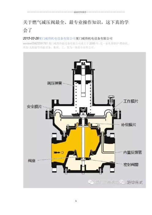
先了解一下燃气减压阀工作原理:弹簧预先加压产生的压力和下游气体反馈回来的压力作用在内部膜片的正反两面,两个压力差的变化会带动阀杆上下运动,在弹簧压力恒定的情况下,下游压力高,阀门就会关小,下游压力低,阀门就会开大;下游压力等于弹簧设定压力,阀门保持不动,起到恒压作用。
当下游用气设备停止,管道没有流量时,阀门会自动关闭。
再来回顾一下我们遇到过的问题。
一、通气后发现减压阀下游压力超高,打坏压力表无数,有木有?没关系,减压阀通气时只要做到以下三点,就可以避免此类问题。
1.一定要缓开上游手动截止阀,能有多慢就多慢,只要有一小股燃气到了减压阀下游,并且下游压力表有了显示并稳定后,再将阀门开到最大。
2.不要将弹簧旋紧太多,越松越好,因为旋紧太多开启度就太大,在减压阀反应之前造成下游超压。
3.一定要开启下游放散。
这个不是指自动放散阀,要有手动放散。
因为减压阀首次通气,下游压力不能马上反馈回来,在下游压力没有反馈之前,阀门不受控,容易超压。
开启放散就是将瞬间高压释放出去,给减压阀一定时间反应。
等压力放散到正常范围,这时关闭手动放散,将减压阀弹簧慢慢旋紧,直到下游压力达到设定值。
二、减压阀下游阀门关闭时,压力保持不住,会逐渐升高,有木有?注:我们不讨论瞬间升高,减压阀下游关闭时压力瞬间升高是正常的,这是因为减压阀反应时间所导致,一般开启手动放散即可恢复到正常压力值。
气体钢瓶减压阀工作原理及使用方法

气体钢瓶减压阀工作原理及使用方法一、气体钢瓶减压阀的工作原理1.弹簧式减压阀:弹簧式减压阀采用弹簧的弹力来控制阀门的开启程度。
当气体压力高于设定值时,弹簧开始受到压力作用,将阀门推向关闭位置,阻止气体通过。
当气体压力低于设定值时,弹簧将阀门推向开启位置,允许气体通过。
2.升降阀:升降阀是一种通过电磁力或气动力将阀芯升降来调节流量的减压阀。
当气体压力高于设定值时,电磁力或气动力收缩,将阀芯向下压低,阻止气体通过。
当气体压力低于设定值时,电磁力或气动力释放,阀芯向上抬高,允许气体通过。
二、气体钢瓶减压阀的使用方法1.安装减压阀:首先,将减压阀的进气口与气体钢瓶的出气口连接,并确保连接处无漏气。
然后,将减压阀的出气口连接到需要减压的设备或管道上。
请注意,减压阀必须安装在气体钢瓶与设备之间,以保护设备免受高压气体的损坏。
2.调节减压阀:使用减压阀之前,必须先调节减压阀的输出压力。
通常,减压阀上会有一个调压旋钮或手柄,通过旋转该旋钮或手柄,可以改变减压阀的弹簧力或电磁力大小,从而改变减压阀的输出压力。
根据需要,将旋钮或手柄逆时针旋转以增加输出压力,或顺时针旋转以减小输出压力。
3.检查漏气:在使用减压阀之前,务必检查减压阀及其连接部件是否有漏气。
可以使用肥皂水或气体泄漏检测仪来检查连接处是否有气体泄漏。
如果发现有泄漏,应立即进行修复或更换。
4.正确认识输出压力:使用减压阀时,必须准确理解输出压力的设定和调节。
了解设备的工作要求和安全规范,选择合适的输出压力范围。
如果输出压力过高,可能会损坏设备或引发危险;如果输出压力过低,可能无法满足设备的工作要求。
总结:气体钢瓶减压阀的工作原理是通过调节介质流过阀门的面积来控制气体流量和压力。
使用气体钢瓶减压阀时,需要正确安装减压阀并调节输出压力,确保阀门和连接部件无漏气,且输出压力符合设备的工作要求和安全规范。
这样可以有效地减压并保护设备安全运行。
减压阀的基本介绍与安装
减压阀的基本介绍与安装减压阀是采用控制阀体内的启闭件的开度来调节介质的流量,将介质的压力降低,同时借助阀后压力的作用调节启闭件的开度,使阀后压力保持在一定范围内,并在阀体内或阀后喷入冷却水,将介质的温度降低,这种阀门称为减压减温阀。
该阀的特点,是在进口压力不断变化的情况下,保持出口听压力和温度值在一定的范围内。
减压阀按结构形式可分为薄膜式、弹簧薄膜式、活塞式、杠杆式和波纹管式;按阀座数目可人为单座式和双座式;按阀瓣的位置不同可分为正作用式和反作用式。
减压阀是一种自动降低管路工作压力的专门装置,它可将阀前管路较高的水压减少至阀后管路所需的水平。
减压阀广泛用于高层建筑、城市给水管网水压过高的区域、矿井及其他场合,以保证给水系统中各用水点获得适当的服务水压和流量。
鉴于水的漏失率和浪费程度几乎同给水系统的水压大小成正比,因此减压阀具有改善系统运行工况和潜在节水作用,据统计其节水效果约为30%。
减压阀的构造类型很多,以往常见的有薄膜式、内弹簧活塞式等。
减压阀的基本作用原理是靠阀内流道对水流的局部阻力降低水压,水压降的范围由连接阀瓣的薄膜或活塞两侧的进出口水压差自动调节。
近年来又出现一些新型减压阀,如定比式减压阀。
定比减压原理是利用阀体中浮动活塞的水压比控制,进出口端减压比与进出口侧活塞面积比成反比。
这种减压阀工作平稳无振动;阀体内无弹簧,故无弹簧锈蚀、金属疲劳失效之虑;密封性能良好不渗漏,因而既减动压(水流动时)又减静压(流量为0时);特别是在减压的同时不影响水流量。
减压阀通常有DN50~DN100等多种规格,阀前、后的工作压力分别为VlMPa和0.l~0.5MPa,调压范围误差为±5%~10%°虽然水流通过减压阀虽有很大的水头损失,但由于减少了水的浪费并使系统流量分布合理、改善了系统布局与工况,因此总体上讲仍是节能的。
减压阀的安装和维护应注意以下事项1、为了操作和维护方便,该阀一般直立安装在水平管道上。
VGBF燃气减压阀
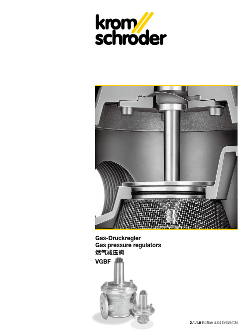
Ausführung
Gehäuse:
Aluminium
Membranen: Perbunan
Ventilsitz:
Aluminium
Ventilspindel: Aluminium
Ventilteller:
aufvulkanisierte Perbunandichtung
Innengewinde: Rp nach ISO 7-1
Flanschanschluss: PN 16 nach ISO 7005
Sonderausführung
(siehe Prospekt T 12.2.3) DN 15 – DN 50 mit NPT-Gewinde, DN 80 – DN 100 mit ANSI-Flansch lieferbar. Anschlüsse der Impulsleitung: NPT.
EG-Baumuster geprüft und zertifiziert
Konstruktion mit Vordruckausgleichsmembrane gewährleistet hohe Regelgenauigkeit
Hohe Durchflussleistung durch optimale Dimensionierung
Keine Atmungsleitung erforderlich
VGBF 05 mit interner Rückmeldung erleichtert die Installation
Gas pressure regulators VGBF
Pressure regulator for gaseous media, to be fitted to all types of gas consuming appliances
气体钢瓶减压阀工作原理及使用方法
气体钢瓶减压阀工作原理及使用方法气体钢瓶减压阀工作原理及使用方法引言气体钢瓶减压阀是一种常见的工业设备,用于控制气体钢瓶中气体的压力,确保气体的安全使用。
本文将介绍气体钢瓶减压阀的工作原理以及使用方法。
一、气体钢瓶减压阀工作原理气体钢瓶减压阀的工作原理基于压力差和流体力学原理。
下面将详细介绍其工作原理的几个关键步骤:1. 压力传导:当气体钢瓶中的气体压力超过设定压力时,压力将通过减压阀的入口传导到减压阀内部。
2. 弹簧调节:减压阀内部设有弹簧,用于对减压阀的开启压力进行调节。
当气体压力超过弹簧所施加的力时,减压阀门会自动打开,从而降低气体压力。
3. 流体调节:当减压阀门打开后,气体将经过减压阀的节流孔进入减压阀的出口,此时气体的压力将得到调节,达到设定值。
4. 压力均衡:减压阀出口处还设有一个调压室,用于保持阀门关闭时的压力与阀门打开时的压力保持一致,从而保证气体压力的稳定性。
二、气体钢瓶减压阀使用方法正确的使用气体钢瓶减压阀不仅可以保证气体的安全使用,还能延长设备的使用寿命。
下面是使用气体钢瓶减压阀的几个基本步骤:1. 设置合适的工作压力:在使用气体钢瓶减压阀之前,需要根据具体的工作需求,设置合适的工作压力。
这可以通过调节减压阀上的调压装置来实现。
2. 连接气源和用气设备:将气源管道与减压阀的入口相连,并将需要供气的设备与减压阀的出口相连。
3. 打开气体钢瓶:打开气体钢瓶上的阀门,使气体进入减压阀。
4. 调节工作压力:根据实际需要,逐步调节减压阀上的调压装置,使工作压力达到设定值。
5. 检查和维护:定期检查减压阀的工作状态,确保其正常运行。
如果发现任何异常情况,及时进行维修或更换。
气体钢瓶减压阀是一种重要的工业设备,它能够有效控制气体钢瓶中气体的压力,保障使用的安全性。
本文介绍了气体钢瓶减压阀的工作原理和使用方法,希望能对读者有所帮助。
在使用减压阀时,请务必根据设备要求正确设置工作压力,并定期进行检查和维护,以确保其正常运行。
气体减压阀工作原理
气体减压阀工作原理气体减压阀(Pressure Reducing Valve, PRV)是一种常见的工业控制装置,它的主要功能是通过减小流体的压力,将高压气体降压到合适的工作压力范围内,以满足特定的流量和压力要求。
气体减压阀广泛应用于各种工业、商业和民用场合,如天然气输送、石油炼化、化工生产、发电厂等。
首先,气体减压阀包括一个主阀体、一个调节膜片和一个弹簧组件。
主阀体通常由一个进气口、一个出气口和一个阀芯孔组成。
调节膜片通过一个阀芯连接到主阀体上,并位于阀芯孔的入口处。
弹簧组件连接在调节膜片的另一侧,并与主阀体相连。
当气体进入主阀体时,通过调节膜片的变形和弹簧的压缩,气体压力被调节到所需的工作压力下。
其次,当气体进入主阀体时,气体流经进气口,并由阀芯孔进入阀芯孔入口。
进入阀芯孔后,气体会作用在调节膜片的内侧,使其向下变形。
调节膜片的弹性特性使其可以像弹簧一样变形,以适应不同的压力变化。
调节膜片的向下变形会拉开阀芯,从而增加阀芯孔的通道,使气体能够顺畅地通过主阀体,从出气口排出。
当气体压力达到设定的工作压力时,调节膜片上的弹簧开始起作用。
弹簧会向上施加力量,使得调节膜片返回初始位置,同时阀芯孔的通道被减小,限制气体从出气口流出。
这种反馈机制可以使气体减压阀在不同压力条件下保持稳定的输出压力。
此外,为了增加在不同工作负荷下的减压阀的灵活性和精确性,通常在主阀体的进口和出口之间安装一个调压器和一个调压控制器。
调压器可以自动调节气体流量和压力,以保持恒定的输出压力。
调压控制器可以根据需要调整主阀体的开度,以进一步控制输出气体的压力。
总结起来,气体减压阀通过调节膜片和弹簧的变形以及阀芯孔的开度,实现从高压气体到合适的工作压力范围的降压。
这种自动控制系统可以确保在不同工作条件下气体压力的稳定性和可靠性。
随着科技的发展和工业的进步,气体减压阀的设计和制造也得以不断改进和创新,以满足不断变化的流体控制需求。
燃气车气体减压阀工作原理
燃气车气体减压阀工作原理
燃气车的气体减压阀是一个重要的安全装置,其主要功能是将高压的液化石油气(LPG)从气罐中减压并输出到发动机燃烧室中。
以下是燃气车气体减压阀的工作原理:
1. 液化石油气进入减压阀:首先,高压的液化石油气由管道输送至减压阀的入口。
2. 减压阀压力调节:减压阀内部有一个调节装置,可以通过调整阀门开启度来控制输出气体的压力。
当输入气体的压力超过设定值时,阀门会自动调节开启度,使其减压到合适的压力。
3. 减压阀放散废气:在减压过程中,气体会引起压力差,因此一部分不需要的气体会通过安全放散装置排出。
这样可以确保系统内部的压力维持在安全范围内。
4. 输出到发动机燃烧室:减压后的燃气将被送入发动机燃烧室,与空气混合并被点燃。
这样可以提供动力用于驱动车辆。
需要注意的是,燃气车的气体减压阀还会配备一系列的安全装置,例如过压保护装置、逆流阀和限制装置等,以确保车辆的安全运行。
这些装置可以在发生异常情况下,如过压或逆流,保护减压阀和整个燃气系统不受损坏,并防止可能的事故发生。
燃气减压阀的作用及原理

燃气减压阀的作用及原理燃气减压阀是一种用于将高压气体减压至需要的低压的装置。
它广泛应用于燃气系统、工业生产和民用家居等领域。
燃气减压阀的作用以及原理涉及到流体力学、热力学和机械工程等多个学科。
燃气减压阀的作用是通过减小燃气流经的截面积,使高压气体在通过减压阀时发生压力降,从而达到减压的目的。
它能够保护下游设备或管道免受高压气体的损害,并稳定地提供所需的低压气体。
燃气减压阀的原理可以简单地分为以下几个方面:1. 弹簧原理:燃气减压阀通常采用弹簧结构,利用弹簧的压力来平衡压力差,控制阀门的开启度。
当进入减压阀的高压燃气流经阀门时,阀门受到上游压力的作用而被推开;而通过调整弹簧的预紧力,可以使得阀门在达到所需的低压时关闭。
2. 流体动力学原理:燃气减压阀通过改变流体的速度来改变压力。
当高压燃气进入减压阀内部时,由于出口为较小的截面积,流体速度加快,根据贝努利方程,流体速度增加时压力会降低。
这种基于流体速度和截面积之间的关系来实现减压的原理称为伯努利原理。
3. 调节装置:燃气减压阀通常还配备了调节装置,可以根据需要调整阀门的开启度,从而实现精确控制燃气的压力。
调节装置可以采用手动、电动、气动或液压的方式,具体根据实际需求而定。
随着科技的发展,燃气减压阀的设计和制造已经逐渐趋于智能化和自动化。
现代化的燃气减压阀可以实现远程监控和控制,具有高精度和良好的安全性能。
在设计和使用燃气减压阀时,需要根据实际情况考虑许多因素,如流量、压力差、介质特性等。
总之,燃气减压阀的作用是将高压气体减压至需要的低压,以保护设备和管道的安全运行,并提供稳定的燃气供应。
其原理主要基于弹簧原理和流体动力学原理,并通过调节装置实现精确控制。
燃气减压阀在现代工业和生活中发挥着重要的作用,促进了社会的发展和生产力的提高。
气体钢瓶减压阀工作原理及使用方法
气体钢瓶减压阀工作原理及使用方法气体钢瓶减压阀是一种用于调节和降低高压气体的压力的装置。
它广泛应用于工业生产和实验室等领域,以保证气体的安全使用。
下面将详细介绍气体钢瓶减压阀的工作原理及使用方法。
一、工作原理:气体钢瓶减压阀的工作原理主要是通过调节钢瓶中气体流出的速度,从而使气体的压力保持在一个适宜的范围内。
其具体的工作原理如下:1. 弹簧控制:气体钢瓶减压阀内部设置有一个弹簧,其承担着调节气体流出速度的作用。
当钢瓶中气体的压力超过设定值时,弹簧将受到压力的作用而收缩,从而打开减压阀的通道,使气体缓慢地流出。
当气体压力降低到设定范围内时,弹簧恢复原状,减压阀通道关闭,停止气体的流出。
2. 气体流道控制:气体钢瓶减压阀内部具有各种密封件和导流件,通过这些部件将钢瓶中的高压气体引导到减压阀,并通过减压阀排出。
这些部件的结构和材质对减压阀的性能和使用寿命有着重要的影响。
二、使用方法:正确和安全地使用气体钢瓶减压阀是保障操作人员和设备安全的关键。
下面是一些常见的使用方法:1. 安装:首先,需要选择合适的减压阀型号和规格,根据钢瓶中气体的压力和流量要求来选择。
然后,将减压阀的进气口与钢瓶的出气口连接。
确保连接处密封可靠,防止气体泄漏。
2. 调节压力:打开钢瓶上的阀门,使气体流入减压阀。
通过旋转减压阀上的调节旋钮,可逐渐调节减压阀的输出压力。
根据实际需要,将输出压力设定为合适的数值。
3. 监测和维护:在使用减压阀的过程中,应随时注意监测减压阀的工作状态,确保正常运行。
如发现异常,如漏气等问题,应及时进行维护和处理。
4. 停止使用:当不需要使用减压阀时,应将减压阀的输出压力调至最低,并关闭钢瓶上的阀门。
确保钢瓶中的气体不会因为持续流出而浪费或造成安全隐患。
总之,气体钢瓶减压阀的工作原理是通过弹簧控制和气体流道控制,将高压气体的压力降低至适宜的范围内。
在使用气体钢瓶减压阀时,需要正确安装、调节压力,并定期监测和维护,以保证设备安全运行。
新国标防爆减压阀
新国标防爆减压阀是一种安全设备,用于降低燃气压力并防止爆炸。
它通常由阀门、减压装置和安全阀组成。
阀门用于控制燃气的流量,减压装置将高压燃气减压为低压燃气,安全阀则可以在发生泄漏或异常情况时自动关闭,防止燃气泄漏和爆炸。
新国标防爆减压阀具有以下特点:
1.符合国家安全标准,能够有效地防止燃气泄漏和爆炸。
2.采用优质材料制造,具有较高的耐压能力和使用寿命。
3.可以根据用户需求进行定制,满足不同用户的需求。
4.安装简单,使用方便,可以有效地提高燃气使用的安全性和可靠性。
需要注意的是,新国标防爆减压阀在使用过程中需要注意以下几点:
1.定期检查阀门、减压装置和安全阀是否正常工作,如有异常及时维修或更
换。
2.在使用过程中要保持燃气管道的清洁和干燥,避免杂物和水分进入管道。
3.在使用过程中要避免碰撞和挤压管道和阀门等部件,以免造成损坏或泄漏。
4.在使用过程中要遵守燃气安全使用规定,不要私自拆卸、修理或改造燃气
设备。
气体钢瓶减压阀工作原理及使用方法
气体钢瓶减压阀工作原理及使用方法概述气体钢瓶减压阀是一种重要的安全装置,用于控制气体钢瓶中的气体压力,并将其降低到安全的工作压力范围内。
本文将介绍气体钢瓶减压阀的工作原理和使用方法,以帮助您正确理解和操作该装置。
工作原理气体钢瓶减压阀主要由弹簧负荷机构、调压机构和阀体组成。
当气体钢瓶中的压力超过设定值时,弹簧负荷机构将施加压力在调压机构上,使其打开减压阀。
此时,高压气体通过阀体进入减压阀内部,经过调压机构的调整,将气体压力降低到安全的工作压力范围内,然后经由减压阀排出。
使用方法1. 确保安全:在使用气体钢瓶前,首先要检查其外观是否有损坏或漏气的迹象。
如果发现异常,请勿使用,避免安全事故发生。
2. 安装减压阀:将气体钢瓶减压阀与气体钢瓶连接,确保其连接牢固。
注意,减压阀应安装在钢瓶上方,以便更好地控制气体压力。
3. 调整工作压力:根据需要,使用调压机构来调整气体钢瓶减压阀的工作压力。
根据应用需要,选择合适的工作压力范围,并确保准确可靠。
4. 监控压力:在使用气体钢瓶时,应定期检查减压阀的工作状态和压力。
如发现异常压力波动或阀体渗漏,请立即停止使用并进行检修。
5. 维护保养:定期对气体钢瓶减压阀进行清洁和维护,保持其正常工作。
同时,检查弹簧负荷机构和调压机构是否正常,保持其灵活和可靠的工作。
注意事项1. 避免超压:使用气体钢瓶减压阀时,应严格遵守其工作压力范围,避免超出其承受能力造成设备损坏或安全事故。
2. 防止污染:在使用气体钢瓶减压阀时,请确保气体的纯度和干净度,避免杂质和污染物进入减压阀,影响其正常工作。
3. 防止冻结:在低温环境下使用气体钢瓶减压阀时,应注意防止减压阀内部冻结,导致减压阀无法正常工作。
可以采取隔热措施或选择耐低温的减压阀进行替换。
结论气体钢瓶减压阀是一种重要的安全装置,用于控制气体钢瓶中气体的压力并确保其在安全范围内工作。
正确理解减压阀的工作原理和使用方法对于保证设备安全和正常运行至关重要。
气体钢瓶减压阀工作原理及使用方法
气体钢瓶减压阀工作原理及使用方法气体钢瓶减压阀工作原理及使用方法●引言本文档旨在介绍气体钢瓶减压阀的工作原理及使用方法,以帮助用户正确、安全地操作钢瓶减压阀。
减压阀在气体贮存和使用过程中起到了重要的作用,使用者需要了解其工作原理以及正确的使用方法,以确保操作安全和效果。
●工作原理1.减压阀的作用减压阀是一种用于减小气体钢瓶中气体压力的装置。
当气体钢瓶内部压力超过设定值时,减压阀会自动开启,将高压气体通过阀门减压释放,以维持瓶内压力在安全范围内。
2.减压阀的结构减压阀通常由以下几个主要部分组成:进气口、出气口、弹簧、活塞、阀座、调节螺母等。
减压阀通过调节螺母的紧固程度来控制弹簧对活塞的压力,进而影响减压阀的开启压力。
3.减压阀的工作过程当气体钢瓶内部压力超过设定值时,该压力作用在活塞上,使其与阀座分离,从而打开减压阀。
高压气体经过减压阀的出气口流出,直至压力降至设定值以下。
当气体钢瓶内部压力减小到设定值以下时,弹簧对活塞施加的压力将使得活塞与阀座重新接触,关闭减压阀,停止气体放出。
●使用方法1.检查钢瓶减压阀的外观是否完好,无裂纹或其他损坏。
如果发现任何问题,请勿使用减压阀,及时更换或修理。
2.确保减压阀与气体钢瓶连接牢固。
使用适当的连接装置,如螺纹连接或快速接头,确保无泄漏。
3.打开钢瓶阀门前,先将减压阀调节螺母旋紧,使其封闭状态。
然后慢慢打开钢瓶阀门,让气体进入减压阀。
4.根据需要,使用调节螺母来控制减压阀的开启压力。
调节螺母顺时针旋转,将增加开启压力;逆时针旋转,将减小开启压力。
5.在使用过程中,始终注意气体钢瓶内压力的变化。
如有异常情况,应立即停止使用,检查原因并采取相应措施。
6.在使用完毕或不需使用时,应将减压阀调节螺母旋紧,使其恢复到封闭状态。
然后关闭钢瓶阀门。
●附件本文档无涉及附件。
●法律名词及注释1.气体贮存和使用安全规范:指针对气体贮存和使用过程中的安全要求制定的相关法规和标准,包括但不限于国家标准、行业标准等。
气体减压阀说明书
气体减压阀说明书一、产品概述气体减压阀是一种广泛应用于气体输送系统的设备,主要作用是将高压气体降低到所需的低压状态。
本产品采用优质材料制造,具有高效、稳定、安全、可靠等优点,适用于各种工业领域的气体控制和调节。
二、产品特点1.高品质材料:气体减压阀的关键部件采用优质材料制造,如不锈钢、铜合金等,具有优异的耐腐蚀性和高强度,确保产品的长期稳定运行。
2.精确控制:气体减压阀具有精确的减压功能,可将气体压力稳定地降低到所需的低压值,有效避免压力波动和瞬间高压对系统的影响。
3.安全可靠:气体减压阀配备安全阀和泄漏保护装置,能够在异常情况下及时切断气源,保护设备和人身安全。
4.易于维护:气体减压阀结构简单,体积小,方便安装和维护。
同时,产品具有较好的耐久性,可使用多年无需更换核心部件。
5.广泛应用:气体减压阀适用于各种工业领域的气体控制和调节,如钢铁、化工、电力、医药等。
三、工作原理气体减压阀的工作原理基于气体动力学原理。
当高压气体通过进口进入减压阀时,经过一系列的减压元件和腔室,将高压气体逐渐降低到所需的低压状态。
在此过程中,减压元件根据系统需求进行调节,使气体压力保持稳定并符合设定值。
最后,低压气体通过出口输出到下游系统。
四、使用说明1.安装:将气体减压阀安装在气体输送管道上,确保连接处密封良好,避免漏气现象。
同时,根据实际需求选择合适的型号和规格。
2.使用:在系统正常运行前,应先开启上游阀门,再缓慢开启下游阀门,使气体逐渐流入系统。
调整减压阀的调节螺钉,使气体压力达到所需值。
3.维护:定期检查气体减压阀的密封件和调节螺钉是否磨损或松动,如有需要应及时更换或调整。
同时,定期清理阀口和管道内的杂质和污垢,确保气体流动畅通无阻。
4.安全:在操作过程中如遇异常情况,如泄漏、压力波动等,应立即停机检查并修复。
同时,为保障安全,建议在减压阀上安装安全阀和泄漏保护装置。
五、注意事项1.气体减压阀应避免在高温、潮湿、多尘的环境中使用,以免影响其正常工作和使用寿命。
燃气减压阀工作原理
燃气减压阀工作原理
燃气减压阀是一种用于调节燃气管道中压力的装置,工作原理如下:
1. 燃气减压阀通过监测管道中的压力变化,将高压燃气引导到阀体的高压进口。
2. 高压燃气通过阀体内的阀芯进入压力室。
压力室内设置有弹簧,它的作用是对阀芯施加一个等于或大于燃气进口压力的力。
3. 当燃气进入压力室时,阀芯会受到压力的作用,被推向阀座方向。
当阀芯上的力大于燃气进口的压力时,阀芯和阀座之间的通道将关闭,阻止进一步流动的燃气。
4. 当管道中的压力下降时,弹簧会收缩,减少对阀芯的压力,使阀芯可以打开通道,允许燃气通过,维持管道中的压力稳定。
5. 燃气减压阀还可以通过调整弹簧的强度来改变阀芯关闭或打开的压力阈值,从而实现对燃气压力的精确调节。
总之,燃气减压阀的工作原理是通过弹簧和阀芯的力平衡,根据管道中的压力变化来自动调节燃气流量,以保持管道中的压力恒定。
气体钢瓶减压阀工作原理及使用方法
气体钢瓶减压阀工作原理及使用方法
气体钢瓶减压阀工作原理及使用方法
工作原理
气体钢瓶减压阀是一种用于减压控制的装置,常用于气体储存与输送系统中。
其工作原理基于压力调节和控制的原理,主要包括以下几个部分:
1. 减压阀体:减压阀体是气体钢瓶减压阀的主要组成部分,通过调节阀体内部的通道形状和尺寸,控制气体流过的流量,从而实现减压的目的。
2. 弹簧:减压阀中的弹簧起到压力调节的作用,通过根据设定的压力值来控制阀门的开启和关闭。
当气体压力超过设定值时,弹簧会将阀门关闭,使气体流动减少,从而减小气体钢瓶的压力。
3. 压力表:减压阀通常配备有压力表,用于实时监测气体钢瓶内的压力。
根据压力表上显示的数值,可以判断当前气体钢瓶内的压力是否处于正常范围内。
使用方法
使用气体钢瓶减压阀时,需要注意以下几点:
1. 安装减压阀:将减压阀正确地安装在气体钢瓶上,确保阀门
与钢瓶的连接牢固,无泄漏现象。
2. 设置压力:根据实际需求,调节减压阀上的压力设置装置,
将减压阀设定到所需的压力数值。
3. 监测压力:使用减压阀时,应当定期监测气体钢瓶内的压力,确保压力始终在正常范围内。
4. 定期维护:定期对减压阀进行检查和维护,保证其正常工作。
如发现阀门损坏或存在泄漏现象,应及时更换或修理。
5. 安全操作:在使用气体钢瓶减压阀时,应遵守相关的安全操
作规程,确保自身和周围人员的安全。
以上是气体钢瓶减压阀的工作原理及使用方法,正确使用减压
阀可以保证气体钢瓶的安全运行和气体的有效利用。
在使用过程中,应当遵循相关的规定和标准,确保操作的安全性和有效性。
20.10.8燃气控制管路的各阀组的作用
燃气控制管路的各阀组的作用20.10.8李明雷(北京创利通达科技有限公司)①手动球阀AKT:结构简单,安全可靠,低扭矩,聚四氟乙烯密封、EC认证;②气体过滤器GFK:用于保护下游设备不受堵塞,过滤流量大,净化效率高,使用寿命长,易于更换滤芯;③压力表KFM、RFM:按量程分类,KFM,mbar压力表;RFM,bar 压力表。
指示精度高,零点校正,超压保护,波登管、膜盒、波纹管三种类型;④压力表阀DH:超压保护压力表,DH 8R50、DH 15R50;⑤超压切断阀JSAV:保护入口段压力调节器和下游的所有控制装置。
正压、超压切断,跳闸压力调节范围大,EU认证,DN25~DN40带低压切断阀、不需要通气管;JSAV 25~40:带硫化NBR密封件的钢,JSAV 50~100:带硫化NBR密封件的铝。
⑥燃气减压阀VGBF:可以调节设定出口压力,并保持恒定,不受天然气管道中气体流速和入口压力变化的影响。
进口压力补偿膜片的设计,可以确保控制精度。
高流速,带导压管可以反馈调节;⑦放散阀VSBV 25:释放系统的压力波动,起到溢流放散稳压的作用,防止安全切断阀JSAV无意中被激活,防止气体蠕动增加压力导致气体压力调节器关闭不严。
入口压力范围高达4bar,可调开启压力20~500mbar。
⑧压力开关DG:气体压力保护装置,起到监测和报警的作用;⑨燃气切断阀VK:液压驱动的安全阀,断电时阀门关闭,开关速度较慢,开关扭矩大,结构坚固,使用寿命长,自动关闭电机可节省能源,最重要的是提供防爆型,一级或两级,可提供闭合位置指示器,入口有滤网可排出阀座上沉积的灰尘颗粒。
两级关闭,90%,可限制气体流速;⑩气体电磁阀VAS:适用于最大入口压力500 mbar;结构设计紧凑,节省空间,易于安装到系统中;由于集成流量调节,无需额外阀门;通过蓝色LED检查指示;带集成视觉位置指示器的闭合开关验证;适合高负荷循环。
⑪空燃比例阀GIK:保持恒定的空气/燃气混合比,用于连续控制的燃烧器;进口压力补偿膜片的设计可以确保控制精度;高量程比;欧盟认证。
液化气减压阀

液化气减压阀液化气减压阀是一种常见的工业设备,用于控制液化气从高压输送管道中降压并稳定输出。
在液化石油气、天然气等行业中广泛应用。
本文将深入介绍液化气减压阀的工作原理、结构特点、应用领域以及维护保养等方面内容。
一、工作原理液化气减压阀通过调节阀芯的开度,控制进入阀体的气体流量,使其在通过阀体过程中获得更低的压力。
当液化气进入减压阀时,通过阀芯和阀座之间的缝隙流过,减小了通道的截面积,从而压力得以降低。
同时,减压阀还提供了稳定的出口压力,确保液化气在运输过程中能够保持一定的工作压力范围。
二、结构特点液化气减压阀通常由阀体、阀芯、弹簧、调节螺母等部件组成。
其中,阀体是对气体进行减压的主要部件,其内部设置有阀芯和阀座。
阀芯与阀体的连接通过螺纹紧固,可以根据需要调整阀芯的开度,从而控制气体流量。
弹簧的作用是提供阀芯的弹性力,使其能够自动适应不同压力范围,并保持稳定的工作状态。
三、应用领域液化气减压阀广泛应用于石油、化工、天然气、锅炉等行业。
主要的应用场景包括:1.液化石油气储存和输送:在液化石油气储罐和管道系统中,减压阀被用于控制压力,确保气体安全稳定地输送到用户端。
2.天然气管道输送:在天然气管道的输送过程中,减压阀起到了关键的作用。
通过减压阀,天然气可以从高压输送管道中降压,以适应用户的需要。
3.工业锅炉:工业锅炉中使用的液化气通常需要降压后才能使用。
减压阀被用于控制液化气进入锅炉的压力,确保锅炉的安全运行。
4.烹饪用气:减压阀还常用于家庭燃气灶具等烹饪设备上。
通过减压阀,将高压液化石油气降压后供给燃气灶具使用,确保安全并控制火力大小。
四、维护保养为了确保液化气减压阀的正常运行,延长其使用寿命,以下是一些建议的维护保养方法:1.定期检查:定期检查减压阀的工作状况,包括是否漏气、阀门是否灵活、阀体是否有异物等。
如发现问题,及时进行维修或更换。
2.清洁阀体:定期清洁阀体内部的杂质和沉积物,以确保阀芯和阀座之间的密封性。
- 1、下载文档前请自行甄别文档内容的完整性,平台不提供额外的编辑、内容补充、找答案等附加服务。
- 2、"仅部分预览"的文档,不可在线预览部分如存在完整性等问题,可反馈申请退款(可完整预览的文档不适用该条件!)。
- 3、如文档侵犯您的权益,请联系客服反馈,我们会尽快为您处理(人工客服工作时间:9:00-18:30)。
VGBF 500 mbar: EN 88, Klasse A, Gruppe 2.
Gegebenenfalls eingebaute Siebe am Ausgang dienen der Strömungsgleichrichtung.
EC type-tested and certified
Design incorporating inlet pressure compensation diaphragm ensures high control accuracy
Optimum dimensioning allows high throughput
Gas-Druckregler Gas pressure regulators 燃气减压阀 VGBF
2.1.1.8 Edition 4.04 D/GB/CN
VGBF..R
VGBF..R
VGBF..F
VGBF..F05
Gas-Druckregler VGBF
Druckregler für gasförmige Medien zum Einbau in jede Art von Gasverbrauchseinrichtungen
VGBF 1 to 4 bar: external control via impulse line: connection Rp ¼ for DN 15 and 25, connection Rp 3/8 for DN 40 – 150.
VGBF 500 mbar: internal control. Connection Rp ¼ for pressure test point or for pilot gas line: at the inlet: VGBF 15 and 25, at the inlet and outlet: VGBF 40 – 150.
Fitting
The design of the pressure regulator is such that the fitting position is irrelevant. The device must
be fitted free of tension and must not touch any constructional parts of its surrounding (e.g. wall, brickwork). Distance 20 mm minimum.
VGBF 1 to 4 bar: Damping valve for impulse line Rp 3/8 – Order No. 75439215 VGBF 15 – 25: not required VGBF DN 40 – 100 4 bar: loosely enclosed Can be supplied for VGBF DN 40 – 150 1 bar on request.
Flange connection: PN 16 to ISO 7005
Special version
(see brochure T 12.2.3) DN 15 – 50 with NPT thread, DN 80 – 100 available with ANSI flange. Connections of the impulse line: NPT.
Strainers that are possibly fitted at the outlet serve as flow straighteners.
技术参数
适用燃气种类:天然气,城市煤气,LPG 液化气和生物甲烷。VGBF..05..L 型也可用 于空气介质。 最大入口压力 pe max: VGBF..05: 500 mbar, VGBF..10: 1 bar, VGBF..40: 4 bar, 出口压力范围: DN 15 – 100: 5 – 350 mbar, DN 150: 5 – 160 mbar。 不同的出口压力范围可以通过选用不同的 弹簧来实现。(详见弹簧选型表) 出厂标准设定为 20mbar(红色弹簧)。
Construction
Housing:
Aluminium
Diaphragms:
Perbunan
Valve seat:
Aluminium
Valve stem:
Aluminium
Valve disc:
with vulcanised Perbunan seal
Internal thread: Rp to ISOhäuse:
Aluminium
Membranen: Perbunan
Ventilsitz:
Aluminium
Ventilspindel: Aluminium
Ventilteller:
aufvulkanisierte Perbunandichtung
Innengewinde: Rp nach ISO 7-1
Technical data
Type of gas: Natural gas, town gas, LPG (gaseous) and biologically produced methane, VGBF..05..L also for air. Max. inlet pressure pe max: VGBF..05: 500 mbar, VGBF..10: 1 bar, VGBF..40: 4 bar. Outlet pressure ranges: DN 15 – 100 : 5 – 350 mbar, DN 150: 5 – 160 mbar. The appropriate outlet pressure range is obtained by the use of different springs (see table: spring selection). The regulator is set to 20 mbar at the works (red spring).
EG-Baumuster geprüft und zertifiziert
Konstruktion mit Vordruckausgleichsmembrane gewährleistet hohe Regelgenauigkeit
Hohe Durchflussleistung durch optimale Dimensionierung
VGBF..F10, VGBF..F40
Technische Daten
Gasart: Erdgas, Stadtgas, Flüssiggas (gasförmig) und Biogas, VGBF..05..L auch für Luft. Max. Eingangsdruck pe max: VGBF..05: 500 mbar, VGBF..10: 1 bar, VGBF..40: 4 bar. Ausgangsdruckbereiche: DN 15 – 100: 5 – 350 mbar, DN 150: 5 – 160 mbar. Der Ausgangsdruckbereich wird erzielt durch den Einsatz unterschiedlicher Federn (s. Tabelle Federbereiche). Die Regler sind werksseitig auf 20 mbar eingestellt (rote Feder).
A purge line is not required
VGBF 05 with internal feedback facilitates installation
燃气减压阀 VGBF
适用于各种燃气介质 经过 EC 测试和认证 采用进口压力补偿设计,调节精度高 高流通量设计 不需要安装呼吸管线 VGBF 05 型压力反馈管内置
VGBF 1 bar 和 4 bar 型: 反馈管外置: DN 15 和 25 阀门接口Rp ¼ , DN 40 – 150 阀门接口Rp 3/8 。 VGBF 500 mbar:反馈管内置。 Rp ¼ 的测压孔接口或点火燃气管路: 入口端: VGBF 15和25, 在进出口端:VGBF 40 – 150, 介质温度范围: -15 – +60 °C。 VGBF 1 bar和4 bar: EN 334 标准 RG 10 调节规定, SG 30 关闭压力规定。 VGBF 500 mbar: EN 88 标准, A级, 2组。 如有条件,阀内出口端可接装滤器波,进 一步降低气流波动。
Einbau
Die Konstruktion des Reglers ermöglicht eine lageunabhängige Montage. Das Gerät ist spannungsfrei und ohne Berührung mit
den es umgebenden Bauteilen des Gebäudes (z. B. Wand, Mauerwerk) einzubauen. Abstand mindestens 20 mm.
Anschluss Rp ¼ für Messstutzen oder auch für Zündgasleitung: am Eingang: VGBF 15 und 25, am Eingang und Ausgang: VGBF 40 – 150.
Temperaturbereich: -15 bis +60 °C.
Temperature range: -15°C to +60°C.
VGBF 1 to 4 bar: EN 334, regulating group RG 10, closing pressure group SG 30.
