可燃气体探测器HD-6000系列说明书
可燃气体检测仪操作说明书及注意事项
XP-3140(单一气体CH4高量程)使用:一、使用程序:装入电池-打开电源-预热运转(显示预热画面ADJ)-检测(显示检测画面)-关闭电源二、注意事项1、必须在洁净空气中接通电源,如气体浓度显示不为零(浓度显示闪烁或上升),则需按AIR键(约按3秒)进行零位调整,显示浓度为零后方可进行检测。
2 切断电源时,返回到洁净空气中,待气体浓度下降后再关闭电源。
3、不得堵塞进气口和排气口4、夜间使用时可按LIGHT键5、此款可燃气体报警器为高量程,可检测可燃气体浓度为0-100%vol(CH4在混合气体中的体积比)。
GASALERTMICROCLIP(四合一)便携式报警器使用一、使用程序:充电-打开电源-进行自检-检测-关闭电源二、注意事项1、此款报警器甲烷检测范围为0-100%LEL(爆炸下限5% vol的百分比),氧气的检测范围为0-30% vol,硫化氢的检测范围为0-100ppm (危险浓度为20ppm),一氧化碳的检测范围为0-500ppm。
2、夜间使用时,可按控制键,背景灯亮。
3、只有显示TEST OK 后方可进行检测。
4、自校零。
在清洁空气环境下,按住○直至屏幕出现OFF倒计时,屏幕暂时关闭时继续按住○。
检测仪此时显示CAL倒计时,按住○直至倒计时完成并进入校准状态。
此时屏幕闪烁,检测仪开始将所有传感器归零,并对氧气传感器进行校准。
5、严禁超量程使用。
6、GASALERTMICROCLIP(单一气体CH4微量)使用方法同上。
GASALERTMICRO(四合一)便携式报警器使用一、使用程序:安装电池-打开电源-进行自检-检测-关闭电源二、注意事项1、此款报警器甲烷检测范围为0-100%LEL(爆炸下限5% vol的百分比),氧气的检测范围为0-30% vol,硫化氢的检测范围为0-100ppm (危险浓度为20ppm),一氧化碳的检测范围为0-500ppm。
2、只有显示TEST 后方可进行检测。
理研计器RM-6000系列指示警报单元使用说明书
PT1cn-1092指示警报单元RM-6000系列使用说明书邮编:174-8744东京都板桥区小豆泽2-7-6主页:https://www.rikenkeiki.co.jp/目录1.产品概要 (2)1-1.前言 (2)1-2.使用目的 (2)1-3.危险、警告、注意、注记的定义 (2)1-4.CE标志认证的确认方法 (3)2.安全上的重要事项 (4)2-1.危险事项 (4)2-2.警告事项 (4)2-3.注意事项 (5)3.产品组成 (6)3-1.主机及附件 (6)3-2.外形图 (7)3-3.各部名称与作用 (8)3-4.框图 (11)4.使用方法 (12)4-1.使用时 (12)4-2.关于安装场所的注意事项 (12)4-3.系统设计上的注意事项 (13)4-4.安装方法 (15)4-5.配线方法 (17)5.操作方法 (25)5-1.启动准备 (25)5-2.基本动作流程 (25)5-3.启动方法 (25)5-4.关于各种模式 (26)5-5.检测模式 (28)5-6.警报测试模式 (30)5-7.用户模式 (31)5-8.结束方法 (35)6.各种动作和功能 (36)6-1.气体警报动作 (36)6-2.故障警报动作 (39)6-3.外部输出动作 (40)6-4.关于各种功能 (42)7.保养检查 (44)7-1.检查频率和检查项目 (44)7-2.定期检查模式 (45)7-3.气体校正方法 (60)7-4.清扫方法 (63)7-5.保险丝的更换方法 (63)8.关于储存、移机和报废 (64)8-1.储存或长期不使用时的处理 (64)8-2.移机或重新使用时的处理 (64)8-3.产品的报废 (64)9.故障排除 (65)10.产品规格 (67)10-1.规格一览 (67)10-2.附件一览 (68)11.术语的定义 (69)1.产品概要1-1.前言感谢您购买气体检测警报器用RM-6000系列指示警报单元。
可燃气体探头说明书
可燃气体探头说明书GAS DETECTOR ZELLWEGER DOCUMENTATIONExcellent PerformanceCertified for hazardous area operation up to+150°C (+302°F)Alarm trip points as low as 5% LELFast speed of responsePoison resistant detectorsLow power consumption Cost EffectiveLow cost disposable sensorGreater than 5 year typical operating lifeReliable OperationSpecially matched ‘Sieger’detectors providehighest stabilityProven technology from the world leader incombustible gas detectionFlexibility ? Measuring ranges from 0-20% LEL to 0-100% LEL ? Wide range of accessories Robust Construction ? 316 Stainless Steel sensor bodyATEX approved designinthe Zone TM PRODUCT DATAThese applications require a sensor that provides reliable andstable detection allowing low levelalarm settings across a wide temperature range.Utilizing a specially matched pair of Sieger poisonresistant combustible gas detection elements,the Sensepoint High Temperature Sensor has a verystable baseline allowing alarm trip points to be set as low as 5% LEL across a temperature range of -40°C to +150°C (-40°F to +302°F).The gas measuring range can be configured from 0-20% LELup to 0-100% LEL depending on the type of controller used.The detector elements are housed in an explosion proof assembly,and provide an industry standard3 wire mV bridge output which can be connected to a suitable control device or converted to an analog output signal via a field transmitter.Sensepoint High T emperature SensorSensepoint High T emperature SensorA Division of the Zellweger Luwa GroupDS303 Issue 2 2106M0612Please Note:While every effort has been made to ensure accuracy in this publication, no responsibility can be accepted for errors or omissions. Data may change, as well as legislation, and you are strongly advised to obtain copies of the most recently issued regulations, standards and guidelines.8376General Specification 1Range: 0-20% LEL, 0-100% LEL (Control card dependent)Speed of Response 2: T60 Less than 6 seconds.T90 Less than 10 seconds.Minimum Alarm Level 3:5% LELOutput Signal:mV bridgeOperating Temperature:-40°C to +150°C (-40°F to +302°F)Operating Humidity:Continuous: 20 to 90% RH Intermittent: 10 to 99% RHOperating Pressure:75 to 110kPa (750 to 1100mbar)Stability (zero):With time:Less than ±5% LEL/yearWith temper ature:Less than ±3% LELWith humidity:Less than ±3% LELWith pressure:Less than ±3% LELStability (span):With time:Less than ±5% LEL/yearWith temperature:Less than ±4% LELWith humidity:Less than ±3% LELWith pressure:Less than ±3% LELLinearity:Better t han ±5% fsdRepeatability:Better than ±2% LELWarm-up Time:30 minutesDetector Operating Life 4:More than 5 years (typical)Storage Life:T ypically, no degredation has been observedin clean, stable conditions for up to 5 yearsPower Consumption:0.7W at 200mAEnclosure Material:316 Stainless SteelMounting Thread:M20, M25 or 3/4 NPTWeight:225g (7.9oz)Baseefa02ATEX0242X II 2G EExd IICATEX:(Assessed for Hazardous area ignition risks)T3 (T amb - 40°to +150°C)Notes: 1. T ypical performance figures for a sensor calibrated on 10%LEL methane and tested at 20°C and 50%RH.2. T60/T90 defined as the time to achieve 60%and 90%of the signal obtained after 5 minutes exposure to 50%FSD gas concentration.3. With recommended 3 month calibration period.4. In clean atmosphere.58mm (2.28in)42mm(1.65in)MAN0622 Issue 01 January 032106M0523The Sensepoint High Temperature (HT) Combustible Gas Sensor is a sealed disposable sensor for the detection of flammable gases. It must be fitted into a suitably approved Exe or Exd high temperature junction box (e.g. Feel Flameproof Enclosures) fitted with an approved cable gland for external wiring (e.g. Peppers Cable Glands, Series A3LF or CR3 CROLOCK Series).The sensor features a Filter Housing that retains a stainless steel mesh filter. It employs a catalytic pellistor sensor device which is used as part of a bridge measuringcircuit.Sensepoint HT is certified for hazardous areas toEN50014/EN50018 and is protected against water and dust ingress to IP66/67. The sensor is available in M20, M25 and 3/4 NPT thread versions. The sensor accepts accessories from a specified range (see Accessories & Spare Parts ).Information notices The types of information notices used throughout this handbook are as follows:Caution:Indicates hazardous or unsafe practice which could result in minor injury to personnel, or product or property damage.Note:Provides useful/helpful/additional information.If more information outside the scope of this technical handbook is required please contact Zellweger Analytics.Associated Documents Sensepoint Gas Sensors Technical Handbook Part No: 2106M05021. INTRODUCTION 12111213148. SPECIFICATIONS 9. ACCESSORIES & SPARE PARTS 7. CERTIFICATION Dimensions:See diagram in Installation section.Operating temperature range:-40°C to +150°C.Operating humidity range:20% to 90% RH continuous.10% to 99% RH intermittent - non condensing.Operating pressure range:75 to 110 k Pa.Warm up time:Less than 10 minutes.Voltage range: 2.9 V to 3.5 V bridge (at 200mA).Power consumption:700mW.Signal output:mV bridge.Calibration flow rate:Recommended between 1 and 1.5 l/min.Poisoning:The sensing elements may become inactive after extensive exposure to silicones,halogenated hydrocarbons,heavy metals or sulphur compounds.Expected operating life: 5 years.IP rating:IP65 standard; IP66/67 with Weather Protection.CE:The sensor complies with relevant CE directives.ATEX Certification:II 2G EEx d II C T3Tamb -40o C to +150o C Baseefa02ATEX0242X Description Part Number Complete replacement sensor:? M20 version 2106B2310? M25 version 2106B2311? 3/4 NPT version 2106B2312Stainless steelfilter 00780-F-0018Filter Housing 00780-C-0038High Temperature Junction Box 2052D0001High Temperature Weather Protection 00780-A-0076Qu i c k S tar t G u i de MEMBERS OF THE ZELLWEGER ANALYTICS DIVISION UK AND INTERNATIONAL ENQUIRIES Zellweger Analytics Ltd Hatch Pond House 4 Stinsford Road Nuffield Estate Poole Dorset BH17 0RZ, UK Tel:+44 (0)1202 676161Fax:+44 (0)1202 678011Email:***************.uk ASIA PACIFIC Zellweger Analytics Ltd Asia Pacific Regional Office 1 Scotts Road #25-04 Shaw Centre Singapore 228208Tel:+65 6862 7701Fax:+65 6862 3858Email:*******************.sgBELGIUMZellwegerAnalytics NV Leuvensesteenweg 392a Chee de Louvain B-1932 Zaventem Belgium Tel:+32 27140311Fax:+32 27140344Email:***************FRANCE Zellweger Analytics France SA Les Fermes Californiennes 62 avenue de l’Europe Emerainville 77436 MARNE LA VALLEE CEDEX 2France T el:33 (1)60 95 45 46Fax:33 (1) 60 95 45 50GERMANY Zellweger Analytics GmbH Sollner Strasse 65b D-81479 Munchen Germany Tel:+49 89791920Fax:+49897919243Email:************************* ITALY Zellweger Analytics srl Via F. Primaticcio 1681-20147 Milano Italy T el:+39 0248 3391Fax:+39 0248 3023 14Email:******************MIDDLE EAST PO Box 52196Dubai UAE Tel:Fax:+971 4 3458 778Email:*******************.ae NETHERLANDS Zellweger Analytics BV Postbus 157NL-3740AD Baarn Tel:+31 (0)355435646Fax:+31 (0)355435929Email:************************************** SA Avda Remolar 3108820 El Prat de Llobregat Barcelona Spain Tel:+34 93 379 9611Fax:+34 93 379 8551Email:************** USA Zellweger Analytics, Inc.5089 Bristol Industrial Way Suite B & C Buford, Georgia 30518USA Tel:+1 770 831 4800Toll Free:+1 8005350606Fax:+16785461954Email:****************A company of the Zellweger Luwa Group total environmental solutions This publication is not intended to form the basis of a contract, and the company reserves the right to amend the design and specification of the instruments without notice.The following BASEEFA certification information is imprinted on adjacent faces in two separate blocks on the hexagonal part of the sensor body.CE mark -conforms to all applicable European directives Manufacturer’s trademark &address Identification number of ATEX notified body Product name Year of manufacture/serial number Certification number Explosion protection mark and equipment group&category Certified ambient temperature range Certification code Caution 6. FAULT FINDING2. SAFETY CAUTIONS 1.Atmospheres above 100% LEL may suppress the sensor reading.2.Do not modify or alter the sensor construction as essential safety requirements may be invalidated.3.Install using suitably approved and certified Exe or Exd high temperature junction box, connectors and glands.4.Dispose of in accordance with local disposal regulations.Materials used - Stainless Steel.The following table provides a list of possible faults related to the sensor together with possible causes and remedies.Fault Cause/RemedySensor reads non zero Gas could be present, ensureall the time there is no combustible gas in theatmosphere.Sensor reads non zero Adjust the control system zerowhen no gas is present setting.Sensor reads low when Adjust the control system spangas is applied setting.Sensor reads high when Adjust the control system spangas is applied setting.Sensor reads zero when 1.Check the wiring.gas is applied 2.Check that the protective dischas been removed from thefilter housing.3.Check that the filter is notdirty/obstructed.4.Replace the sensor ifpoisoning is suspected.Table 2Meter Settings * Calibration * Rating of Gas to be Detected Gas 8*7*6*5*4*3*2*1*8*50627695----7*4050617696---6*334150627898--5*263340506379100-4*21263240506380-3*-212632405064812*---25313950641*----25313950Note:These settings must only be used with a calibration gas concentration of 50% LEL. All data at standard temperature and pressure.Example 1.The target gas to be detected is Butane .The calibration gas available is Methane (50% LEL).2.Look up the star rating for each gas from Table 1:Butane = 4*Methane = 6*3.Check the meter settings for 50% LEL calibration gas from Table 2.The reading is 78%.4.The control card should therefore be set to 78%.This gives an accurate reading for Butane, using 50% LEL Methane as a calibration gas.Table 3Meter Multiplication Factors Unit calibrated Unit usedto detect to detect 8*7*6*5*4*3*2*1*8* 1.001.241.521.892.372.98 3.784.837*0.811.001.231.531.922.40 3.053.906*0.660.811.001.241.561.962.493.175*0.530.660.801.001.251.582.002.554*0.420.520.640.801.001.261.602.033*0.340.420.510.640.801.001.271.622*0.260.330.400.500.630.791.001.281*0.210.260.320.390.490.620.781.0078910To calibrate the Sensepoint HT sensor carry out the following procedure:1.Obtain the star rating for both the test gas and the gas to be detected from T able 1.e the values in Table 2 to obtain the required meter setting when a 50% LEL test gas is applied to the detector.If a sensor is to be used to detect a gas other than that for which it was calibrated, the required correction factor may be obtained from Table 3. The meter reading should be multiplied by this number in order to obtain the true gas concentration.Important Notes:1.Since combustible sensors require oxygen for correct operation,a mixture of gas in air should be used for calibration purposes.2.Assuming an average sensor performance, the sensitivityinformation i n Tables 1 to 3 is normally accurate to ± 20%.Table 1 Star Rating of GasesGasStar Rating Gas Star Rating Acetone4*Hexane 3*Ammonia7*Hydrogen 6*Benzene3*Methane 6*Butane4*Octane 3*Diethyl ether4*Propan-2-ol 4*Ethane6*Propane 5*Ethanol5*Styrene 2*Ethyl acetate3*Tetra hydrafuran 4*Ethylene 5*Xylene 2*Only a qualified installation engineer should service the sensor. Ensure power is off before carrying out any maintenance procedures.The only maintenance required is sensor replacement and filter changing (if fitted to an accessory). T o replace the complete sensor refer to the Sensepoint Gas Sensors T echnical Handbook. T o replace the filter carry out the following procedure:1.Remove the High Temperature Weather Protection accessory.2.Remove the old filter and replace with a fresh filter.3.Replace the Weather Protection accessory.。
可燃气体探测器HD-6000系列说明书

HD-6000系列点型可燃气体探测器使用说明书深圳市宏达瑞斯科技有限公司感谢您使用深圳市宏达瑞斯科技有限公司系列产品,当您准备使用本产品时请务必仔细阅读本说明。
并按照所提供的有关操作步骤进行,使您能充分享受我公司提供的服务,同时避免您的误操作而损坏本机或发生其它意外。
请妥善保管本手册,以便在您日后需要时能及时查阅、获得帮助。
版权声明本手册版权属深圳市宏达瑞斯科技有限公司所有,未经书面许可,本手册任何部分不得复制、翻译、存储于数据库或检索系统内,也不可以电子、翻拍、录音等任何手段及方式进行传播。
深圳市宏达瑞斯科技有限公司秉承科技进步原则,不断致力于产品改进、提高产品性能,公司保留任何产品改进而不预先通知的权利。
如果用户不依照本手册说明擅自安装或修理更换部件,由此产生的责任由用户负责。
产品及产品颜色、款式请以购买的实物为准。
用户服务指引:1在使用本产品前,请根据产品出厂清单仔细核对附件、产品合格证及用户保修卡是否齐全,若发现不全,请立即与销售商或厂家联络。
2本产品自售出之日起十二个月内,凡用户遵守贮存、运输及使用要求,而产品质量低于技术指标的,凭保修单享受免费维修。
3因违反操作规定和要求而造成的损坏、非我公司指定的特约技术服务部维修引起的故障或由于不可抗拒因素引起的产品质量问题,我公司将进行收费维修。
4产品进行维修时,请主动出示产品保修卡。
不能出示产品保修卡的将作为收费维修。
5产品维护、维修后,请出示本手册,维修人员将填写所附的《维护、维修情况记录》并签名;同时也请您在维修人员的《维护、维修情况记录》上签名确认维护、维修内容并提出宝贵意见,如果是单位用户,请加盖公章。
6如果您对我们提供的产品和服务有任何疑问或不满,包括产品技术、质量、安装维修、服务态度、收费标准等问题,请您及时联络我们,我们将会对您的意见妥善处理。
目录1概述 (1)2技术指标 (1)3 产品结构 (2)4 安装与接线说明 (3)4.1 安装位置 (3)4.2 安装方法 (3)4.3探测器接线 (3)5 常见故障及解决办法 (4)6 注意事项 (5)1概述HD-6000系列点型可燃气体探测器是我公司生产的新型气体检测仪器,其突出特点是采用高性能催化燃烧气敏元器件结合精良SMD工艺制造而成,具有良好的重复性和抗湿温度干扰性、使用寿命长、操作方便等优点。
6000数显表说明书
XMT — 6000 系列仪表使用说明书目录一、概述(1)、主要特点(2)、型号定义二、技术规格三、面板说明及操作说明(1)、面板说明(2)、操作说明1、上电过程2、给定值/手动输出值设置3、启动自整定4、参数设置四、参数功能及设置(1)、参数速查表(2)、参数详细说明1、软件参数锁Loc2、与仪表输入有关的参数(SN、DIP、DIL、DIH、DL、SC)3、与仪表报警输出有关的参数(HIAL、LOAL、DHAL、DLAL、DF、ALP)4、与控制输出有关的参数(CF、OP1、OPL、OPH、CTRL、RUN)5、与自整定有关的PID控制参数(M50、P、T)6、与仪表通讯/变送输出有关的参数(CF、ADDR、BAUD、DIL、DIH)7、现场参数(EP1—EP8)五、仪表接线六、典型应用XMT—6000D系列仪表使用说明书目录一、概述(1)、功能简述(2)、型号定义二、面板说明及操作说明(1)、面板说明(2)、操作说明1、设置程序2、设置参数3、显示及修改程序运行段号4、显示运行时间5、运行时修改程序曲线6、运行/暂停(run/HoLd)7、停止(StoP)8、自整定(AT)三、概念解释四、程序编排与操作(1)、时间设置(2)、给定值设置(3)、程序的输入操作(4)、运行多条曲线时程序的编排方法(5)、外部事件输入接口五、停电处理六、与XMT—6000系列仪表的不同之处1、系统运行参数2、参数设置权限选择Loc3、输出定义参数oP14、功能参数CF5、现场定义参数(EP1—EP8)6、仪表与计算机通讯XMT—6000系列仪表使用说明书一、概述(一)主要特点:◆采用先进的微电脑芯片及技术,减小了体积,并提高了可靠性及抗干扰性能。
适用于各种温度,压力,流量,液位, 湿度等的测量控制。
◆按国际标准制造,具备85—265VAC宽围输入的自由电源供选配,备有多种安装尺寸。
◆输入采用数字校正系统及自校准技术,测量精确稳定,消除了温漂及时漂引起的测量误差。
FLIR SC6000系列产品说明书
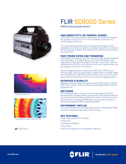
FLIR SC6000 SeriesMWIR science grade cameraHIGH SENSITIVITY, HD THERMAL IMAGESFLIR SC6000 Series incorporate a cooled Indium Antimonide (InSb) detector that operates in the 3 to 5 or 1 to 5 micron waveband. It produces crisp thermal images of 640 x 512.Four active preset operating modes provide adjustable integration times,embedded non-uniformity correction, and bad pixel replacement. An exclusive SC6700 4-position motorized filter wheel permits effortless filter exchange in any environment.FAST FRAME RATES AND TRIGGERINGFLIR SC6000 Series features fast frame rates with a high speed 50 megapixel clock that streams 14-bit digital data up to 126 Hz at full resolution. They support FPA windowing for even higher frame rates. Output frame rates are adjustable from 0.0015 Hz to the maximum frame rate at a given window size and integration time with 0.1 Hz resolution.Advanced triggering options through external BNC input, IRIG time, or asoftware trigger; clock out single images, multiple images, or multiple images from multiple presets. IRIG-B timing is built directly into camera for on-board deterministic time-stamping of each frame and advanced triggering options.INTERFACE FLEXIBILITYMultiple simultaneous analog and digital outputs include S-video, composite (BNC) NTSC and PAL, SVGA, and industry-standard digital Camera Link and Gigabit Ethernet.SOFTWAREThe FLIR SC6000 Series cameras work seamlessly together with FLIRResearchIR Max software enabling intuitive viewing, recording and advanced processing of the thermal data provided by the camera. Each camera comes standard with this especially for R&D applications developed software. A Software Developers Kit (SDK) is optionally available.MATHWORKS® MATLABControl the SC6000 Series and capture data directly into MathWorks ® Matlab software for advanced image analysis and processing.KEY FEATURES• High image quality: 640 x 512 pixels • High speed• Configuration flexibility • Filter wheel• On-camera Radiance and Thermographic Calibration737 across the sunStop-motion image of spinning tireImaging SpecificationsSpecifications are subject to change without notice©Copyright 2014, FLIR Systems, Inc. All other brand and product names are trademarks of their respective owners. The images displayed may not be representative of the actual resolution of the camera shown. Images for illustrative purposes only. (Created 08/14) NASDAQ: FLIRPORTLANDCorporate Headquarters FLIR Systems, Inc.27700 SW Parkway Ave.Wilsonville, OR 97070USAPH: +1 866.477.3687BELGIUMFLIR Systems Trading Belgium BVBALuxemburgstraat 22321 Meer BelgiumPH: +32 (0) 3665 5100SWEDENFLIR Systems AB Antennvägen 6, PO Box 7376SE-187 66 Täby SwedenPH: +46 (0)8 753 25 00NASHUAFLIR Systems, Inc.9 Townsend West Nashua, NH 06063USAPH: +1 603.324.7611UKFLIR Systems UK 2 Kings Hill Avenue Kings HillWest Malling - Kent ME19 4AQUnited KingdomPH: +44 (0)1732 220 011。
gp6000 说明书
gp6000 说明书(1)使用探测器时,应注意危险场所的级别要与仪器的防爆标志相适应。
探测器的防爆类别、级别、组别必须符合现场爆炸性气体混合物的类别、级别、组别的要求。
不得在超过防爆标志所允许的环境中使用,否则起不到现场防爆作用。
(2)探测器不能在含硫、砷、磷、卤素化合物的场所中使用。
因为它们会使探测器中的检测元件中毒,使探测器灵敏度下降,使用寿命缩短,严重的还会使探测器失效。
要对含有上述元素化合物的可燃气体进行检测,应选用抗毒性催化燃烧型探测器或半导体型探测器。
由于催化燃烧型探测器对氢气有引爆性,因此对于氢气的检测应选用电化学型或半导体型探测器。
(3)探测器不能在可燃气体浓度高于爆炸下限的环境条件下使用。
因为催化燃烧型检测器使用的检测元件是载体催化活性元件,检测可燃气体浓度高于爆炸下限的浓度时,将烧坏探测器内的检测元件。
(4)注意不要使探测器意外进水或受水蒸气喷射。
因为探测器中的检测元件进水后会影响其性能,如果意外进水,要重新更换探测器内的检测元件。
安装于室外的探测器则应装有防雨罩。
(5)探测器安装位置的高低要与被测气体的密度相适应。
比空气轻的气体总是向上扩散,检测器应安装在泄漏源的上方。
安装高度应高出释放源所在高度0.5--2m,且与释放源的水平距离适当减小至5m以内,可以尽快地检测到可燃气体。
比空气重的气体,应安装在泄漏源的下方,且安装高度应高出地面0.3--0.6m。
过低易造成因雨水淋溅对探测器的损害,过高时超出了比空气重的气体易于积聚的高度。
(6)仪器投入运行前,要进行检测器工作电流(电压)的调整。
调整后的电流(电压)值应在仪器使用说明书规定的范围内,以保证检测器的正常工作。
此电流(电压)调整后,除正常检修外,一般无需再动。
(7)维护仪器时,不得在仪器通电的情况下现场拆装探测器。
拆装防爆零部件时要小心,注意不要损伤隔爆面和夹杂脏物。
(8)要正确选取报警器的安装位置。
报警器属非防爆部分,固定安装于安全场所。
可燃气体检测报警器使用说明书
可燃气体检测报警器使用说明书可燃气体检测报警器使用说明书一、产品介绍可燃气体检测报警器是一种用于监测环境中可燃气体浓度的设备。
它通过探测细胞感应环境中的气体浓度,并根据设定的报警阈值来发出声光报警信号,以提醒用户可能存在的可燃气体泄漏风险。
二、产品特点1. 高精度检测:可燃气体检测报警器采用先进的传感技术,能够准确地检测环境中的可燃气体浓度,并具备较高的灵敏度。
2. 快速响应:一旦探测到可燃气体浓度超过设定阈值,报警器能够迅速发出声光报警信号,及时提醒用户采取相应的安全措施。
3. 易于安装:报警器仅需通过固定底座即可简便地安装在墙壁或天花板上,操作简单便捷。
4. 可调节灵敏度:用户可以根据实际需要在设备上调节报警阈值,以适应不同环境下的可燃气体浓度要求。
三、使用方法1. 安装:将报警器的固定底座固定在适合的位置(如墙壁或天花板),确保安装牢固。
2. 接通电源:将报警器的插头插入插座,确保报警器能够正常供电。
3. 设定报警阈值:根据实际需求,通过旋转报警器上的调节钮,调整报警器的灵敏度。
请注意,过低的灵敏度可能会导致漏报,而过高的灵敏度可能会导致误报。
4. 测试功能:按下报警器上的测试按钮,检查报警器的声音和灯光是否正常工作。
若正常工作,则表示报警器已经准备就绪。
5. 日常使用:报警器在正常运行期间,会不断监测环境中的可燃气体浓度。
一旦浓度超过设定的阈值,报警器将发出声光报警信号。
此时,请立即采取相应的安全措施,如关闭燃气源、通风或呼叫专业人员进行处理。
同时,必要时可以自行进行排气处理,并确保事态安全。
四、注意事项1. 定期检查:请定期检查报警器的工作状态,确认报警器是否有正常的电源供应和运行状态。
2. 避免遮挡:报警器在安装时,请确保周围没有物体阻挡报警器,以免影响报警器的正常工作。
3. 防水防潮:报警器在安装的位置应避免受到雨水或水汽的影响,以免造成故障。
4. 防尘处理:保持报警器的清洁,避免积尘影响传感器的工作效果。
可燃气体检测仪使用说明书
可燃气体检测仪使用说明书一、产品概述可燃气体检测仪是一款用于检测空气中可燃气体浓度的专业设备。
它采用高精度传感器和先进的检测技术,能够快速准确地监测可燃气体的浓度,并通过声光报警系统提醒用户。
本产品广泛应用于工业、石化、矿山等领域,是保障人员生命安全和工作环境的重要设备。
二、产品特点1.高精度传感器:可燃气体检测仪采用了最新一代的高精度传感器,能够实时监测气体浓度并进行精确测量,保证了检测结果的准确性和可靠性。
2.多种报警方式:可燃气体检测仪具备声光报警功能,当检测到可燃气体浓度超过设定阈值时,会发出声音和光线警报,提醒用户及时采取应对措施。
3.便携轻巧:产品体积小巧,重量轻便,方便携带。
用户可以随身携带,进行随时随地的气体检测。
4.多种气体检测:可燃气体检测仪支持多种可燃气体的检测,如甲烷、乙烷、丙烷等,可以满足不同行业的需求。
三、使用方法1.准备工作:确保设备已充电,检查传感器和使用环境是否正常。
2.开机操作:按下电源开关,待设备自检完成后即可开始工作。
3.设置阈值:根据实际需求,设置合理的报警阈值,保证及时准确的报警。
4.气体检测:将可燃气体检测仪靠近待检测气体区域,等待一段时间,观察仪器显示的浓度数值,并留意是否有报警信号。
5.结果分析:根据测量结果,判断气体浓度是否超标,采取相应的应对措施,保障人员的安全。
四、注意事项1.使用设备前,请阅读并理解本使用说明书,掌握设备的正确使用方法。
2.使用过程中,应保持设备表面干燥,避免雨水或其他物质进入设备,影响正常使用。
3.仪器在使用过程中,应避免剧烈撞击或摔落,以免损坏设备和降低检测准确性。
4.定期校准:为了确保测量结果的准确性,建议定期对设备进行校准和维护,根据实际情况选择合适的校准方法。
5.更换传感器:当设备显示不准确或无法正常工作时,请联系专业人员更换传感器。
6.请勿私自拆解设备,以免造成设备损坏或使用不当。
五、维护保养1.定期充电:请根据使用频率,定期对设备进行充电,确保足够的电量供应。
可燃气体探头说明书
GAS DETECTOR ZELLWEGER DOCUMENTATIONExcellent Performance• Certified for hazardous area operation up to+150°C (+302°F)• Alarm trip points as low as 5% LEL• Fast speed of response• Poison resistant detectors• Low power consumption Cost Effective• Low cost disposable sensor• Greater than 5 year typical operating lifeReliable Operation• Specially matched ‘Sieger’detectors providehighest stability• Proven technology from the world leader incombustible gas detectionFlexibility • Measuring ranges from 0-20% LEL to 0-100% LEL • Wide range of accessories Robust Construction • 316 Stainless Steel sensor body• ATEX approved designinthe Zone TM PRODUCT DATAThese applications require a sensor that provides reliable and stable detection allowing low levelalarm settings across a wide temperature range.Utilizing a specially matched pair of Sieger poisonresistant combustible gas detection elements,the Sensepoint High Temperature Sensor has a verystable baseline allowing alarm trip points to be set as low as 5% LEL across a temperature range of -40°C to +150°C (-40°F to +302°F).The gas measuring range can be configured from 0-20% LELup to 0-100% LEL depending on the type of controller used.The detector elements are housed in an explosion proof assembly,and provide an industry standard3 wire mV bridge output which can be connected to a suitable control device or converted to an analog output signal via a field transmitter.Sensepoint High T emperature SensorSensepoint High T emperature SensorA Division of the Zellweger Luwa GroupDS303 Issue 2 2106M0612Please Note:While every effort has been made to ensure accuracy in this publication, no responsibility can be accepted for errors or omissions. Data may change, as well as legislation, and you are strongly advised to obtain copies of the most recently issued regulations, standards and guidelines.8376General Specification 1Range: 0-20% LEL, 0-100% LEL (Control card dependent)Speed of Response 2: T60 Less than 6 seconds.T90 Less than 10 seconds.Minimum Alarm Level 3:5% LELOutput Signal:mV bridgeOperating Temperature:-40°C to +150°C (-40°F to +302°F)Operating Humidity:Continuous: 20 to 90% RH Intermittent: 10 to 99% RHOperating Pressure:75 to 110kPa (750 to 1100mbar)Stability (zero):With time:Less than ±5% LEL/yearWith temperature:Less than ±3% LELWith humidity:Less than ±3% LELWith pressure:Less than ±3% LELStability (span):With time:Less than ±5% LEL/yearWith temperature:Less than ±4% LELWith humidity:Less than ±3% LELWith pressure:Less than ±3% LELLinearity:Better than ±5% fsdRepeatability:Better than ±2% LELWarm-up Time:30 minutesDetector Operating Life 4:More than 5 years (typical)Storage Life:T ypically, no degredation has been observedin clean, stable conditions for up to 5 yearsPower Consumption:0.7W at 200mAEnclosure Material:316 Stainless SteelMounting Thread:M20, M25 or 3/4 NPTWeight:225g (7.9oz)Baseefa02ATEX0242X II 2G EExd IICATEX:(Assessed for Hazardous area ignition risks)T3 (T amb - 40°to +150°C)Notes: 1. T ypical performance figures for a sensor calibrated on 10%LEL methane and tested at 20°C and 50%RH.2. T60/T90 defined as the time to achieve 60%and 90%of the signal obtained after 5 minutes exposure to 50%FSD gas concentration.3. With recommended 3 month calibration period.4. In clean atmosphere.58mm (2.28in)42mm(1.65in)SENSEPOINT HT COMBUSTIBLE GAS SENSORMAN0622 Issue 01 January 032106M0523The Sensepoint High Temperature (HT) Combustible Gas Sensor is a sealed disposable sensor for the detection of flammable gases. It must be fitted into a suitably approved Exe or Exd high temperature junction box (e.g. Feel Flameproof Enclosures) fitted with an approved cable gland for external wiring (e.g. Peppers Cable Glands, Series A3LF or CR3 CROLOCK Series).The sensor features a Filter Housing that retains a stainless steel mesh filter. It employs a catalytic pellistor sensor device which is used as part of a bridge measuring circuit.Sensepoint HT is certified for hazardous areas to EN50014/EN50018 and is protected against water and dust ingress to IP66/67. The sensor is available in M20, M25 and 3/4 NPT thread versions. The sensor accepts accessories from a specified range (see Accessories & Spare Parts ).Information notices The types of information notices used throughout this handbook are as follows:Caution:Indicates hazardous or unsafe practice which could result in minor injury to personnel, or product or property damage.Note:Provides useful/helpful/additional information.If more information outside the scope of this technical handbook is required please contact Zellweger Analytics.Associated Documents Sensepoint Gas Sensors Technical Handbook Part No: 2106M05021. INTRODUCTION 12111213148. SPECIFICATIONS 9. ACCESSORIES & SPARE PARTS 7. CERTIFICATION Dimensions:See diagram in Installation section.Operating temperature range:-40°C to +150°C.Operating humidity range:20% to 90% RH continuous.10% to 99% RH intermittent - non condensing.Operating pressure range:75 to 110 k Pa.Warm up time:Less than 10 minutes.Voltage range: 2.9 V to 3.5 V bridge (at 200mA).Power consumption:700mW.Signal output:mV bridge.Calibration flow rate:Recommended between 1 and 1.5 l/min.Poisoning:The sensing elements may become inactive after extensive exposure to silicones,halogenated hydrocarbons,heavy metals or sulphur compounds.Expected operating life: 5 years.IP rating:IP65 standard; IP66/67 with Weather Protection.CE:The sensor complies with relevant CE directives.ATEX Certification:II 2G EEx d II C T3Tamb -40o C to +150o C Baseefa02ATEX0242X Description Part Number Complete replacement sensor:• M20 version 2106B2310• M25 version 2106B2311• 3/4 NPT version 2106B2312Stainless steel filter 00780-F-0018Filter Housing 00780-C-0038High Temperature Junction Box 2052D0001High Temperature Weather Protection 00780-A-0076Qu i c k S tar t G u i de MEMBERS OF THE ZELLWEGER ANALYTICS DIVISION UK AND INTERNATIONAL ENQUIRIES Zellweger Analytics Ltd Hatch Pond House 4 Stinsford Road Nuffield Estate Poole Dorset BH17 0RZ, UK Tel:+44 (0)1202 676161Fax:+44 (0)1202 678011Email:sales@ ASIA PACIFIC Zellweger Analytics Ltd Asia Pacific Regional Office 1 Scotts Road #25-04 Shaw Centre Singapore 228208Tel:+65 6862 7701Fax:+65 6862 3858Email:zalasia@.sg BELGIUM Zellweger Analytics NV Leuvensesteenweg 392a Chee de Louvain B-1932 Zaventem Belgium Tel:+32 27140311Fax:+32 27140344Email:zabl@ FRANCE Zellweger Analytics France SA Les Fermes Californiennes 62 avenue de l’Europe Emerainville 77436 MARNE LA VALLEE CEDEX 2France Tel:33 (1) 60 95 45 46Fax:33 (1) 60 95 45 50GERMANY Zellweger Analytics GmbH Sollner Strasse 65b D-81479 Munchen Germany Tel:+49 89 791 920Fax:+49 89 791 9243Email:vertriebscenter@zelana.de ITALY Zellweger Analytics srl Via F. Primaticcio 1681-20147 Milano Italy Tel:+39 0248 3391Fax:+39 0248 3023 14Email:zaitaly@ MIDDLE EAST PO Box 52196Dubai UAE Tel:Fax:+971 4 3458 778Email:zelana@.ae NETHERLANDS Zellweger Analytics BV Postbus 157NL-3740AD Baarn Tel:+31 (0)355435646Fax:+31 (0)355435929Email:zabl@ SPAIN Zellweger Analytics SA Avda Remolar 3108820 El Prat de Llobregat Barcelona Spain Tel:+34 93 379 9611Fax:+34 93 379 8551Email:zellana@jet.es USA Zellweger Analytics, Inc.5089 Bristol Industrial Way Suite B & C Buford, Georgia 30518USA Tel:+1 770 831 4800Toll Free:+1 800 535 0606Fax:+1 678 546 1954Email:sales@A company of the Zellweger Luwa Group total environmental solutions This publication is not intended to form the basis of a contract, and the company reserves the right to amend the design and specification of the instruments without notice.The following BASEEFA certification information is imprinted on adjacent faces in two separate blocks on the hexagonal part of the sensor body.CE mark -conforms to all applicable European directives Manufacturer’s trademark &address Identification number of ATEX notified body Product name Year of manufacture/serial number Certification number Explosion protection mark and equipment group&category Certified ambient temperature range Certification code Caution 6. FAULT FINDING2. SAFETY CAUTIONS 1.Atmospheres above 100% LEL may suppress the sensor reading.2.Do not modify or alter the sensor construction as essential safety requirements may be invalidated.3.Install using suitably approved and certified Exe or Exd high temperature junction box, connectors and glands.4.Dispose of in accordance with local disposal regulations.Materials used - Stainless Steel.The following table provides a list of possible faults related to the sensor together with possible causes and remedies.Fault Cause/RemedySensor reads non zero Gas could be present, ensureall the time there is no combustible gas in theatmosphere.Sensor reads non zero Adjust the control system zerowhen no gas is present setting.Sensor reads low when Adjust the control system spangas is applied setting.Sensor reads high when Adjust the control system spangas is applied setting.Sensor reads zero when 1.Check the wiring.gas is applied 2.Check that the protective dischas been removed from thefilter housing.3.Check that the filter is notdirty/obstructed.4.Replace the sensor ifpoisoning is suspected.Table 2Meter Settings * Calibration * Rating of Gas to be Detected Gas 8*7*6*5*4*3*2*1*8*50627695----7*4050617696---6*334150627898--5*263340506379100-4*21263240506380-3*-212632405064812*---25313950641*----25313950Note:These settings must only be used with a calibration gas concentration of 50% LEL. All data at standard temperature and pressure.Example 1.The target gas to be detected is Butane .The calibration gas available is Methane (50% LEL).2.Look up the star rating for each gas from Table 1:Butane = 4*Methane = 6*3.Check the meter settings for 50% LEL calibration gas from Table 2.The reading is 78%.4.The control card should therefore be set to 78%.This gives an accurate reading for Butane, using 50% LEL Methane as a calibration gas.Table 3Meter Multiplication Factors Unit calibrated Unit used to detect to detect 8*7*6*5*4*3*2*1*8* 1.001.241.521.892.372.98 3.784.837*0.811.001.231.531.922.40 3.053.906*0.660.811.001.241.561.962.493.175*0.530.660.801.001.251.58 2.002.554*0.420.520.640.801.001.26 1.602.033*0.340.420.510.640.801.00 1.271.622*0.260.330.400.500.630.79 1.001.281*0.210.260.320.390.490.620.781.0078910To calibrate the Sensepoint HT sensor carry out the following procedure:1.Obtain the star rating for both the test gas and the gas to be detected from Table 1.e the values in Table 2 to obtain the required meter setting when a 50% LEL test gas is applied to the detector.If a sensor is to be used to detect a gas other than that for which it was calibrated, the required correction factor may be obtained from Table 3. The meter reading should be multiplied by this number in order to obtain the true gas concentration.Important Notes:1.Since combustible sensors require oxygen for correct operation,a mixture of gas in air should be used for calibration purposes.2.Assuming an average sensor performance, the sensitivityinformation in Tables 1 to 3 is normally accurate to ± 20%.Table 1 Star Rating of GasesGasStar Rating Gas Star Rating Acetone4*Hexane 3*Ammonia7*Hydrogen 6*Benzene3*Methane 6*Butane4*Octane 3*Diethyl ether4*Propan-2-ol 4*Ethane6*Propane 5*Ethanol5*Styrene 2*Ethyl acetate3*Tetra hydrafuran 4*Ethylene 5*Xylene 2*Only a qualified installation engineer should service the sensor. Ensure power is off before carrying out any maintenance procedures.The only maintenance required is sensor replacement and filter changing (if fitted to an accessory). To replace the complete sensor refer to the Sensepoint Gas Sensors Technical Handbook. To replace the filter carry out the following procedure:1.Remove the High Temperature Weather Protection accessory.2.Remove the old filter and replace with a fresh filter.3.Replace the Weather Protection accessory.。
可燃气体探测器安装与配置说明书
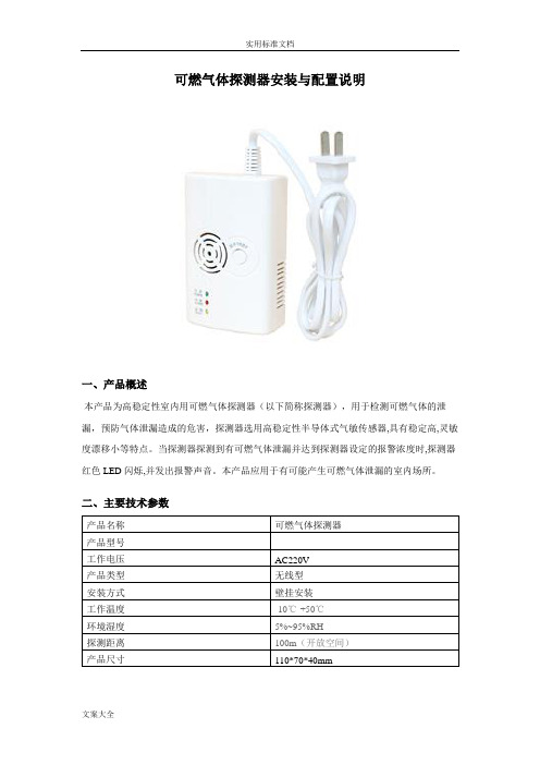
可燃气体探测器安装与配置说明一、产品概述本产品为高稳定性室内用可燃气体探测器(以下简称探测器),用于检测可燃气体的泄漏,预防气体泄漏造成的危害,探测器选用高稳定性半导体式气敏传感器,具有稳定高,灵敏度漂移小等特点。
当探测器探测到有可燃气体泄漏并达到探测器设定的报警浓度时,探测器红色LED闪烁,并发出报警声音。
本产品应用于有可能产生可燃气体泄漏的室内场所。
二、主要技术参数三、安装注意事项1、首先确定所需检测的气体比空气重或比空气轻,比空气重的气体:液化石油气等;比空气轻的气体:天然气、人工煤气、沼气等。
2、根据燃气的轻重在合适的地方安装探测器。
探测比空气重的气体时:安装于高出地面0.3-1.0米,距气源半径1.5米内;探测比空气轻的气体时:安装于低于天花板0.3-1.0米,距气源半径1.5米内(详见下图)。
3、家庭安装时还应注意,安装位置不能离燃气炉具太近,以免探测器受到炉具火焰的烘烤;不能安装在油烟大的地方,以免引起误报警或导致探测器的进气孔进气不畅,从而影响探测器的感应灵敏度;也不能安装于排气扇、门窗边与浴室水汽较大处。
4、按图正确的接线,所有的接线安装必须符合国家及地方的有效法规、标准。
不恰当的连接将导致在发生燃气泄漏时,不能正常报警。
5、用安装螺丝将探测器支架固定在墙面,挂上探测器。
四、操作说明1、AC供电独立型探测器:将电源插头直接插入220V市电插座即可正常工作。
2、接通探测器电源,电源指示灯绿色LED长亮,蜂鸣器“嘀”的一声,电路进入预热状态,这时红色LED与黄色LED交替闪烁,闪烁约三分钟后停止,表示探测器进入正常工作状态。
预热期间禁止用气体测试。
3、当探测器探测到可燃气体泄漏并达到报警浓度时,报警指示灯红色LED闪烁,同时蜂鸣器发出“嘀-嘀”报警声4、当探测器内部的传感器发生故障时,探测器的黄色LED长亮,蜂鸣器长鸣。
请断开电源,并与当地经销商联系维修处理。
请勿私自拆开探测器,以免造成触电危险。
HD-6000说明书

目录一、开关GPS主机 (2)二、GPS工作模式的设置 (2)三、电台频道设置 (2)四、GPS主机面版灯含义 (3)五、Psion WorkAboutPro手簿操作说明 (4)六、架设基准站 (5)七、手簿与GPS主机的连接(蓝牙无线连接) (5)八、手簿程序的操作流程(转换参数配合高程拟合法) (5)1、新建项目 (6)2.设置基准站 (7)3.断开手簿与基准站GPS主机 (8)4.添加控制点 (9)5.连接手簿与移动站GPS主机 (9)6.移动站设置 (9)7.采集碎部点坐标 (10)8.求解转换参数和高程拟合参数: (12)9.点放样 (16)10.测量成果的导出 (18)九、附录 (21)1.卫星检验 (21)2.接收机复位 (21)3.设置高程拟合模式说明 (21)4.连接程序的安装 (22)5、手簿常用快捷键功能一览表 (28)6.求解七参数的操作 (29)7.计算两点间距离 (31)8.计算校正参数 (32)9.直线放样 (33)10.HD-POWER操作程序的升级 (35)一、开关GPS主机1、按电源键1秒,开机2、按电源键3秒,关机二、GPS工作模式的设置目的:HD6000 RTK具有静态、RTK等功能,事先必须对其主机作相应的基准站、移动站、静态或GPRS 设置。
作静态使用,则所有主机均设为静态方式。
作RTK使用,若用常规UHF电台,则基站设为外挂UHF电台基站方式,移动站设为内置UHF电台移动站方式;若用GPRS通讯,则基站设为内置GPRS基站方式,移动站设为内置GPRS移动站方式。
若作电缆直通实验,即基准站主机与移动站主机用DG-3电缆直接连接检测主机内部串口通讯时,则基站设为外挂UHF电台基站方式,移动站设为外挂数据链移动站方式。
特性:主机一旦设置好后,以后开机则默认为上次设置。
操作步骤:1、开机2、按住键2秒,等卫星灯、接收灯、状态灯同时闪2次后松开3、再一下一下按键N次,卫星灯、接收灯、状态灯三灯状态不同,则工作模式不同4、按键确认三、电台频道设置目的:将基站电台和移动站电台频率设置为一致,移动站才能收到基站信息;就如对讲机频道一样,要调到相同。
可燃气体探测器使用说明书
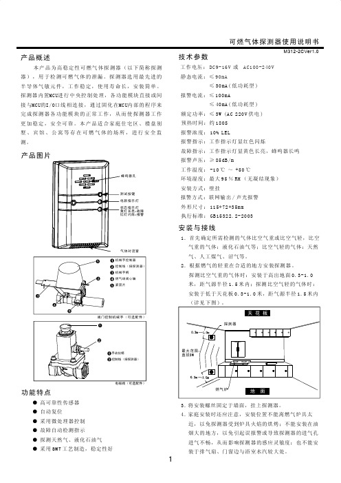
功能特点● 高可靠性传感器 ● 自动复位 ● 采用微处理器控制● 故障自动检测指示 ● 探测天然气、液化石油气 ●采用工艺制造,稳定性好SMT可燃气体探测器使用说明书产品概述本产品为高稳定性可燃气体探测器(以下简称探测器),用于检测可燃气体的泄漏。
探测器选用最先进的半导体气敏元件,工作稳定,使用寿命长,安装简单。
探测器内置MCU进行中央控制处理,各功能模块直接或间接与MCU的I/O口线相连接,通过固化在MCU内部的程序来完成探测器各功能模块的正常工作,从而使探测器工作更加稳定,安全可靠。
本产品适合家庭住宅区、楼盘别墅、宾馆、公寓等存在可燃气体的场所,进行安全监测。
时间:约180S 报警指示:工作指示灯显红色闪烁故障指示:长亮,蜂鸣器长鸣报警声压:≥85dB/m 工作温度:-10℃ ~ +50℃安装方式:壁挂报警方式:联网输出/声光报警外形尺寸: 执行标准:GB15322.2-2003预热工作指示灯显黄色环境湿度:最大95%RH (无凝结现象)** 1157235mm 技术参数DC9-16V AC100-240V 90mA工作电压:或静态电流:≤ ≤30mA(低功耗型)报警电流:≤100mA≤40mA(低功耗型)额定功率:≤3W (AC 220V 供电)报警浓度:10% LEL安装与接线1. 首先确定所需检测的气体比空气重或比空气轻,比空气重的气体:液化石油气等;比空气轻的气体:天然气、人工煤气、沼气等。
2. 根据燃气的轻重在合适的地方安装探测器。
探测比空气重的气体时:安装于高出地面0.3-1.0米,距气源半径1.5米内;探测比空气轻的气体时:安装于低于天花板0.3-1.0米,距气源半径1.5米内(详见下图)。
3.将安装螺丝固定于墙面,挂上探测器。
4.家庭安装时还应注意,安装位置不能离燃气炉具太近,以免探测器受到炉具火焰的烘烤;不能安装在油烟大的地方,以免引起误报警或导致探测器的进气孔进气不畅,从而影响探测器的感应灵敏度;也不能安装于排气扇、门窗边与浴室水汽较大处。
可燃气体传感器用户手册说明书
Catalytic Flammable Gas Sensor(Model: MC106)User’s ManualVersion: 1.1Valid from: 2018-03-15Zhengzhou Winsen Electronics Technology Co., LtdStatementThis manual copyright belongs to Zhengzhou Winsen Electronics Technology Co., LTD. Without the written permission, any part of this manual shall not be copied, translated, stored in database or retrieval system, also can’t spread through electronic, copying, record wa ys.Thanks for purchasing our product. In order to let customers use it better and reduce the faults caused by misuse, please read the manual carefully and operate it correctly in accordance with the instructions. If users disobey the terms or remove, disassemble, change the components inside of the sensor, we shall not be responsible for the loss.The specific such as color, appearance, sizes …etc., please in kind prevail.We are devoting ourselves to products development and technical innovation, so we reserve the right to improve the products without notice. Please confirm it is the valid version before using this manual. At the same time, users’ comments on optimized using way are welcome.Please keep the manual properly, in order to get help if you have questions during the usage in the future.Zhengzhou Winsen Electronics Technology CO., LTDMC106 Catalytic Flammable Gas Sensor ProductMC106 adopts catalytic combustion principle, and its twoarms of electric bridge consists of a test element and acompensate element. The resistance of the test elementrises once it meets the combustible gases, in the sametime, the output voltage of the bridge changes and thevoltage variation rises in direct proportion to the gasconcentration. The compensate element, as a conference,has the function of compensating temperature andhumidity.FeaturesBridge output voltage in linearFast responseGood repeatability and selectivityResist H2S poisoning & organosilicone.Main ApplicationsIt is widely used in industrial occasion to detect theconcentration of natural gas, LPG, coal gas and alkanes.It is also used in combustible gas leakage alarm system,combustible gas detector and gas concentration meterand so on.Parameters:Model MC106Sensor Type Catalytic TypeStandard Encapsulation PlasticWorking voltage(V) 2.5±0.1Working current(mA) 150±10Sensitivity (mV) 1% CH4 20~50 1% C3H830~70Linearity ≤5% Measuring range(%LEL) 0~100 Response Time (90%) ≤10s Recovery Time (90%) ≤30s Working Environment -40~+70℃<95%RH Storage Environment -20~+70℃<95%RH Lifespan 5 yearsFig1. Sensor StructureFig2. Basic Test Circuit Testing voltage: 2.5VBridge outputSensitivity and Response FeatureChanging of output signal at different temperatureChanging of output signal at different humidity0204060801001201400%1%2%3%4%5%6%输出电压m V浓度灵敏度曲线甲烷丙烷-50510152025010203040Fig4. Response and recovery curve recovery curveFig5.Zero point at different temp.Fig6. Sensitivity at different temp.Fig7.Zero point at different humidity Fig8. Sensitivity at different humidityFig3. Sensitivity CurveResponse & Recovery CurveHum. CurveHum. CurveHumidityHumidityCH4 C3H8 ℃Changing of output signal with different voltage supplyingLong-term Stability The drift in air per year is within ±2mV, in 1%CH 4 is within ±2mV. For a short period storage (in 2 weeks), the sensor need be galvanical continuously for 8 hours to reach stability. For long period storage (one year), it need 48 hours.Cautions1 .Following conditions must be prohibited1.1 Exposed to organic silicon steamSensing material will lose sensitivity and never recover if the sensor absorbs organic silicon steam. Sensors must avoid exposing to silicon bond, fixature, silicon latex, putty or plastic contain silicon environment. 1.2 High Corrosive gasIf the sensors are exposed to high concentration corrosive gas (such as H 2S, SO X , Cl 2, HCl etc.), it will not only result in corrosion of sensors structure, also it cause sincere sensitivity attenuation. 1.3 Alkali, Alkali metals salt, halogen pollutionThe sensors performance will be changed badly if sensors be sprayed polluted by alkali metals salt especially brine, or be exposed to halogen such as fluorine. 1.4 Touch waterFig11. Zero and Sensitivity stability curveFig10.Sensitivity with different voltageIn Air1% CH4Time (weeks)Fig9.Zero Drift with different voltageSensitivity of the sensors will be reduced when spattered or dipped in water.1.5 FreezingDo avoid icing on sensor’s surface, otherwise sensing material will be broken and lost sensitivity.1.6 Applied higher voltageApplied voltage on sensor should not be higher than stipulated value, even if the sensor is not physically damaged or broken, it causes down-line or heater damaged, and bring on sensors’ sensitivity characteristic changed badly.1.7 Pins connectionWhen the sensor is connecting to the circuit, one of detection part pins and one of compensation part pins connects as the signal output. The other pin of detection part connects negative electrode, while the other pin of compensation part connects positive electrode. The part with “D” mark on the sensor bottom is the detection one, the other part with “C” mark is the compensation one.2 .Following conditions must be avoided2.1 Water CondensationIndoor conditions, slight water condensation will influence sensors’ performance lightly. However, if water condensation on sensors surface and keep a certain period, sensors’ sensitive will be decreased.2.2 Used in high gas concentrationNo matter the sensor is electrified or not, if it is placed in high gas concentration for long time, sensors characteristic will be affected. If lighter gas sprays the sensor, it will cause extremely damage.2.3 Long time storageThe sensors resistance will drift reversibly if it’s stored for long time without electrify, this drift is related with storage conditions. Sensors should be stored in airproof bag without volatile silicon compound. For the sensors with long time storage but no electrify, they need long galvanical aging time for stability before using. The suggested aging time is 24 hours at least if the storage time is more than half an year.2.4 Long time exposed to adverse environmentNo matter the sensors electrified or not, if exposed to adverse environment for long time, such as high humidity, high temperature, or high pollution etc., it will influence the sensors’ performance badly. 2.5 VibrationContinual vibration will result in sensors down-lead response then break. In transportation or assembling line, pneumatic screwdriver/ultrasonic welding machine can lead this vibration.2.6 ConcussionIf sensors meet strong concussion, it may lead its lead wire disconnected.2.7 Usage Conditions2.7.1For sensor, handmade welding is optimal way. The welding conditions as follow:●Soldering flux: Rosin soldering flux contains least chlorine●Homothermal soldering iron●Temperature:250℃●Time:less than 3 seconds2.7.2 If users choose wave-soldering, the following conditions should be obey:●Soldering flux: Rosin soldering flux contains least chlorine●Speed: 1-2 Meter/ Minute●Warm-up temperature:100±20℃●Welding temperature:250±10℃●One time pass wave crest welding machineIf disobey the above using terms, sensors performance will get worse.。
可燃气体探测器使用说明书

.言非常感谢您选择本公司仪器!在使用本产品前,请详细阅读本说明书,请遵守本说明书操作规程及注意事项,并保存以供参考。
♦由于不遵守本说明书中规定的注意事项,所引起的任何故障和损失均不在厂家的保修范围内,厂家亦不承担任何相关责任。
请妥善保管好所有文件。
如有疑问,请联系我公司售后服务部门。
♦如果您需要电子版说明书,请登陆本公司网站下载,或拨打服务热线,联系我公司售后服务部门。
♦在收到仪器时,请小心打开包装,检查仪器及配件是否因运送而损坏,如有发现损坏, 请联系我公司售后服务部门,并保留包装物,以便寄回处理。
♦当仪器发生故障,请勿自行修理,请联系我公司售后服务部门。
♦本说明书适用于V4.00系列的产品版本。
以下标识将会在本手册或者仪器上出现:接地端保险丝公司简介大连因斯特科技有限公司是专注于自动化领域的仪器仪表设计、制造、销售、安装、售后服务为一体的现代化高新技术企业,公司与国内外知名仪表企业精诚合作,采用进口原件研制生产具有国内领先、国际先进的自控仪表产品,开发“因斯特”品牌系列分析、流量、液位、压力等在线监测产品,长期与国外诸多知名仪表企业进行技术交流合作,产品不但性能品质过硬,还融入了符合中国思维模式的操作菜单界面。
产品不断更新换代,自投入市场以来,广泛应用于自来水、污水处理、石油、化工、电力、冶金、环保、制药等行业,得到了广大用户的一致好评。
公司拥有高级职称技术人员十余名,并长期与大连工业大学等高校合作,为企业不断输入技术、销售等多方面人才,确保满足不同客户的服务需求。
公司自主研发、生产、营销:PH计、ORP仪化学膜溶解氧(DO、荧光法溶解氧(DO)、浊度计(SS)、余氯检测仪、电导率、光电污泥浓度计(MLSS)超声波污泥浓度计、超声波泥水界面仪、超声波液位计、超声波液位差计、超声波明渠流量计、电磁流量计(DN15-DN200、超声波流量计、COD在线监测仪、氨氮在线监测仪、总磷(TP)在线监测仪、总氮(TN)在线监测仪、总磷总氮一体机、六价铬在线检测仪、总铜在线分析仪、总镍在线分析仪、总铬在线分析仪、总镉在线分析仪、总砷在线分析仪、总铅在线分析仪、总汞在线分析仪、总锰在线分析仪、挥发酚在线分析仪、氰化物在线分析仪、氟化物在线分析仪。
可燃气体检测仪操作说明书及注意事项

XP-3140(单一气体CH高量程)使用:4一、使用程序:装入电池-打开电源-预热运转(显示预热画面人口))-检测(显示检测画面)-关闭电源二、注意事项1、必须在洁净空气中接通电源,如气体浓度显示不为零(浓度显示闪烁或上升),则需按AIR键(约按3秒)进行零位调整,显示浓度为零后方可进行检测。
2 切断电源时,返回到洁净空气中,待气体浓度下降后再关闭电源。
3、不得堵塞进气口和排气口4、夜间使用时可按LIGHT键5、此款可燃气体报警器为高量程,可检测可燃气体浓度为 0-100%vol(CH,在混合气体中的体积比)。
GASALERTMICROCLIP (四合一)便携式报警器使用一、使用程序:充电-打开电源-进行自检-检测-关闭电源二、注意事项1、此款报警器甲烷检测范围为0-100%LEL (爆炸下限5% vol的百分比),氧气的检测范围为0-30% vol,硫化氢的检测范围为0-100ppm (危险浓度为20ppm), 一氧化碳的检测范围为0-500ppm。
2、夜间使用时,可按控制键,背景灯亮。
3、只有显示TEST OK后方可进行检测。
4、自校零。
在清洁空气环境下,按住。
直至屏幕出现OFF倒计时,屏幕暂时关闭时继续按住。
检测仪此时显示CAL倒计时,按住。
直至倒计时完成并进入校准状态。
此时屏幕闪烁,检测仪开始将所有传感器归零,并对氧气传感器进行校准。
5、严禁超量程使用。
6、GASALERTMICROCLIP (单一气体CH微量)使用方法同上。
4GASALERTMICRO (四合一)便携式报警器使用一、使用程序:安装电池-打开电源-进行自检-检测-关闭电源二、注意事项1、此款报警器甲烷检测范围为0-100%LEL (爆炸下限5% vol的百分比),氧气的检测范围为0-30% vol,硫化氢的检测范围为0-100ppm (危险浓度为20ppm),一氧化碳的检测范围为0-500ppm。
2、只有显示TEST后方可进行检测。
燃气分析仪操作说明书

燃气分析仪操作说明书一、简介燃气分析仪是一种广泛应用于工业、环保、能源等领域的仪器设备。
本操作说明书将详细介绍燃气分析仪的正确使用方法,以及各项功能的操作流程和注意事项。
二、器材准备在操作燃气分析仪之前,请确保以下器材准备完备:1. 燃气分析仪主机及相应附件:包括传感器、探头、样品管等;2. 电源线:确保设备能正常供电;3. 校准气体:根据需要选择合适的校准气体;4. 手册和软件:熟悉燃气分析仪的功能和使用方法。
三、操作步骤1. 连接电源:将燃气分析仪主机与电源线连接,确保仪器能正常供电。
2. 开机与初始化:按下电源开关,待仪器启动并初始化完成后,进入待机状态。
3. 校准:根据需要进行仪器的校准。
首先将仪器与校准气体连接,按下校准按钮,并按照仪器屏幕上的指引完成校准的各项参数输入。
4. 取样:用样品管将待测气体引入燃气分析仪,确保样品管与探头连接紧密,同时避免气体泄漏。
5. 开始分析:按下分析开始按钮,根据仪器的工作模式和设定参数,仪器将开始对待测气体进行分析。
6. 结果显示与记录:将分析结果显示在仪器屏幕上,并注意记录或保存相关数据。
同时,根据需要可以将结果通过打印、导出或其他方式进行输出。
7. 关机与清理:在使用完毕后,按照仪器的关机步骤操作,关闭燃气分析仪并进行相关的清理工作。
确保仪器存放在干燥、通风的环境中。
四、注意事项1. 安全使用:操作燃气分析仪时,请佩戴防护手套和眼镜,注意防护措施,避免发生意外。
2. 适用范围:燃气分析仪适用于各类燃气的分析,但需要根据不同气体的特点和分析要求进行相应调整。
3. 校准间隔:定期校准燃气分析仪是确保测试结果准确可靠的重要手段,建议按照仪器说明进行校准,校准间隔根据实际使用情况来确定。
4. 清洁保养:燃气分析仪外壳及配件应保持清洁,避免灰尘、水汽等对仪器的影响。
同时,注意及时更换传感器和探头等易耗部件。
5. 技术支持:若在使用过程中遇到任何问题,请及时与设备供应商或相关技术支持人员联系,以获得帮助和解决方案。
最新版HD6000说明书0607
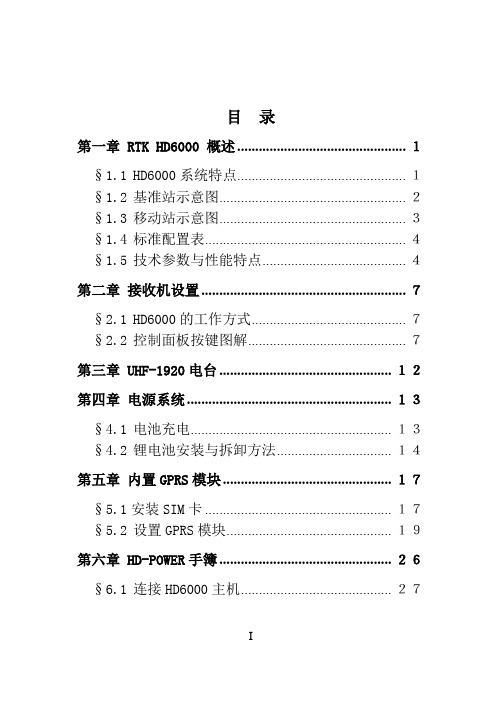
目录第一章 RTK HD6000 概述 ............................................... 1§1.1HD6000系统特点............................................... 1§1.2基准站示意图.................................................... 2§1.3移动站示意图.................................................... 3§1.4标准配置表........................................................ 4§1.5技术参数与性能特点........................................ 4第二章接收机设置 ......................................................... 7§2.1HD6000的工作方式........................................... 7§2.2控制面板按键图解............................................ 7第三章 UHF-1920电台 ................................................ 12第四章电源系统 ......................................................... 13§4.1电池充电........................................................ 13§4.2锂电池安装与拆卸方法................................ 14第五章内置GPRS模块 ............................................... 17§5.1安装SIM卡 .................................................... 17§5.2设置GPRS模块.............................................. 19第六章 HD-POWER手簿 ................................................ 26§6.1连接HD6000主机.......................................... 27I§6.2连接电脑........................................................ 30§6.3复位................................................................ 32§6.4新增功能........................................................ 33第七章静态测量数据下载 ......................................... 36§7.1安装USB驱动程序........................................ 36§7.2USB方式下载数据......................................... 40§7.3串口方式下载数据 ........................................ 41§7.4接收机设置 .................................................... 42第八章作业模式 ......................................................... 43§8.1使用UHF-1920电台作业 .............................. 43§8.2使用内置GPRS模块作业 .............................. 44§8.3水上测量........................................................ 45§8.4静态测量........................................................ 48II第一章RTK HD6000概述第一章 RTK HD6000 概述HD6000网络RTK GPS是中海达公司研制的第五代全新RTK GPS 系统。
FLIR SC6000系列产品说明书
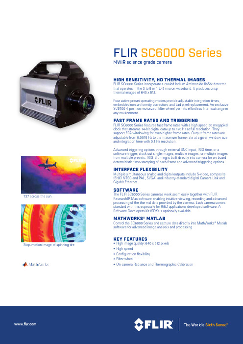
FLIR SC6000 SeriesMWIR science grade cameraHIGH SENSITIVITY, HD THERMAL IMAGESFLIR SC6000 Series incorporate a cooled Indium Antimonide (InSb) detector that operates in the 3 to 5 or 1 to 5 micron waveband. It produces crisp thermal images of 640 x 512.Four active preset operating modes provide adjustable integration times,embedded non-uniformity correction, and bad pixel replacement. An exclusive SC6700 4-position motorized filter wheel permits effortless filter exchange in any environment.FAST FRAME RATES AND TRIGGERINGFLIR SC6000 Series features fast frame rates with a high speed 50 megapixel clock that streams 14-bit digital data up to 126 Hz at full resolution. They support FPA windowing for even higher frame rates. Output frame rates are adjustable from 0.0015 Hz to the maximum frame rate at a given window size and integration time with 0.1 Hz resolution.Advanced triggering options through external BNC input, IRIG time, or asoftware trigger; clock out single images, multiple images, or multiple images from multiple presets. IRIG-B timing is built directly into camera for on-board deterministic time-stamping of each frame and advanced triggering options.INTERFACE FLEXIBILITYMultiple simultaneous analog and digital outputs include S-video, composite (BNC) NTSC and PAL, SVGA, and industry-standard digital Camera Link and Gigabit Ethernet.SOFTWAREThe FLIR SC6000 Series cameras work seamlessly together with FLIRResearchIR Max software enabling intuitive viewing, recording and advanced processing of the thermal data provided by the camera. Each camera comes standard with this especially for R&D applications developed software. A Software Developers Kit (SDK) is optionally available.MATHWORKS® MATLABControl the SC6000 Series and capture data directly into MathWorks ® Matlab software for advanced image analysis and processing.KEY FEATURES• High image quality: 640 x 512 pixels • High speed• Configuration flexibility • Filter wheel• On-camera Radiance and Thermographic Calibration737 across the sunStop-motion image of spinning tireImaging SpecificationsSpecifications are subject to change without notice©Copyright 2014, FLIR Systems, Inc. All other brand and product names are trademarks of their respective owners. The images displayed may not be representative of the actual resolution of the camera shown. Images for illustrative purposes only. (Created 08/14) NASDAQ: FLIRPORTLANDCorporate Headquarters FLIR Systems, Inc.27700 SW Parkway Ave.Wilsonville, OR 97070USAPH: +1 866.477.3687BELGIUMFLIR Systems Trading Belgium BVBALuxemburgstraat 22321 Meer BelgiumPH: +32 (0) 3665 5100SWEDENFLIR Systems AB Antennvägen 6, PO Box 7376SE-187 66 Täby SwedenPH: +46 (0)8 753 25 00NASHUAFLIR Systems, Inc.9 Townsend West Nashua, NH 06063USAPH: +1 603.324.7611UKFLIR Systems UK 2 Kings Hill Avenue Kings HillWest Malling - Kent ME19 4AQUnited KingdomPH: +44 (0)1732 220 011。
- 1、下载文档前请自行甄别文档内容的完整性,平台不提供额外的编辑、内容补充、找答案等附加服务。
- 2、"仅部分预览"的文档,不可在线预览部分如存在完整性等问题,可反馈申请退款(可完整预览的文档不适用该条件!)。
- 3、如文档侵犯您的权益,请联系客服反馈,我们会尽快为您处理(人工客服工作时间:9:00-18:30)。
HD-6000系列
点型可燃气体探测器
使用说明书
深圳市宏达瑞斯科技有限公司
感谢您使用深圳市宏达瑞斯科技有限公司系列产品,当您准备使用本产品时请务必仔细阅读本说明。
并按照所提供的有关操作步骤进行,使您能充分享受我公司提供的服务,同时避免您的误操作而损坏本机或发生其它意外。
请妥善保管本手册,以便在您日后需要时能及时查阅、获得帮助。
版权声明
本手册版权属深圳市宏达瑞斯科技有限公司所有,未经书面许可,本手册任何部分不得复制、翻译、存储于数据库或检索系统内,也不可以电子、翻拍、录音等任何手段及方式进行传播。
深圳市宏达瑞斯科技有限公司秉承科技进步原则,不断致力于产品改进、提高产品性能,公司保留任何产品改进而不预先通知的权利。
如果用户不依照本手册说明擅自安装或修理更换部件,由此产生的责任由用户负责。
产品及产品颜色、款式请以购买的实物为准。
用户服务指引:
1在使用本产品前,请根据产品出厂清单仔细核对附件、产品合格证及用户保修卡是否齐全,若发现不全,请立即与销售商或厂家联络。
2本产品自售出之日起十二个月内,凡用户遵守贮存、运输及使用要求,而产品质量低于技术指标的,凭保修单享受免费维修。
3因违反操作规定和要求而造成的损坏、非我公司指定的特约技术服务部维修引起的故障或由于不可抗拒因素引起的产品质量问题,我公司将进行收费维修。
4产品进行维修时,请主动出示产品保修卡。
不能出示产品保修卡的将作为收费维修。
5产品维护、维修后,请出示本手册,维修人员将填写所附的《维护、维修情况记录》并签名;同时也请您在维修人员的《维护、维修情况记录》上签名确认维护、维修内容并提出宝贵意见,如果是单位用户,请加盖公章。
6如果您对我们提供的产品和服务有任何疑问或不满,包括产品技术、质量、安装维修、服务态度、收费标准等问题,请您及时联络我们,我们将会对您的意见妥善处理。
目录
1概述 (1)
2技术指标 (1)
3 产品结构 (2)
4 安装与接线说明 (3)
4.1 安装位置 (3)
4.2 安装方法 (3)
4.3探测器接线 (3)
5 常见故障及解决办法 (4)
6 注意事项 (5)
1概述
HD-6000系列点型可燃气体探测器是我公司生产的新型气体检测仪器,其突出特点是采用高性能催化燃烧气敏元器件结合精良SMD工艺制造而成,具有良好的重复性和抗湿温度干扰性、使用寿命长、操作方便等优点。
适应于工业环境中检测气体浓度。
HD-6000系列点型可燃气体探测器可将空气中可燃气体浓度信号转化为电信号输出远传,采用三线制结构,由监控仪表或控制器远离现场察看探测结果。
适用于炼油厂、化工厂、液化气站、燃气锅炉房、加油加气站、喷漆房等使用易燃品的工业现场进行气体安全检测报警。
1.1 本产品设计、制造、检定遵守以下国家标准:
GB3836.1-2000 《爆炸性气体环境用电气设备第1部分:通用要求》
GB3836.2-2000 《爆炸性气体环境用电气设备第2部分:隔爆型“d”》GB15322.1-2003
《可燃气体探测器第1部分:测量范围为0~100%LEL的点型可燃气体探测器》
1.2 本产品经国家制定的法定权威机关审查及检验,并通过防爆合格检验。
2技术指标
其它技术指标
检测原理:催化燃烧式;
使用气体:天然气(甲烷)、液化气(异丁烷、丙烷)、煤气(氢气)、戊烷、炔类、烯类、等可燃性气体,酒精、丙酮、苯、甲苯、乙醚、汽油、
柴油等液体蒸汽;
采样方式:自然扩散;
环境温度:-40℃~70℃;
相对湿度:<95%;
防爆等级:Ex dⅡCT6;
电源:DC24V±25%;
功耗:2W/路;
使用电缆: 1.5mm2×3 、1.5mm2×4(四线制)电缆线;
传输距离:≤1000m;
整机重量:≤1200g ;
压力限制:86kPa~106kPa。
3 产品结构
探测器由外壳、电子线路板、催化燃烧式传感器等部分组成,结构如下图所示:
图1 探测器外壳结构图
4 安装与接线说明
4.1 安装位置
4.1.1可燃气体探测器选点应选择阀门、管道接口、出气口或易泄漏处附近方圆1m的范围内,尽可能靠近,但不要影响其它设备操作,同时尽量避免高温、高湿环境。
4.1.2可燃气体检测探头安装高度:检测氢气、天然气、城市煤气等比重小于空气的气体时,采用距屋顶1 m左右安装;检测液化石油气等比重大于空气的气体时,采用距地面0.3 m~0.6 m左右安装。
4.1.3可燃气体检测探头根据SH3063-1999石油化工企业可燃气体和有毒气体检测报警设计规范,探测范围室内7.5米,室外15米,如大面积气体检测探测范围可适当扩大,也可达到检测报警效果。
4.1.4气体检测探头安装时应传感器朝下固定,锁紧螺母应完全拧紧,探头盖应完全盖好,用螺钉拧紧,以达到防爆要求。
4.2 安装方法
在探测现场选择无腐蚀性气体、油烟、尘埃的安装位置,避免水浸。
安装方法参照如下:
如果用户要把探测器安装在墙面上,可先根据上图2所示的探测器结构尺寸选择合适的墙面,然后用三个M6×60的膨胀螺栓对准探测器的安装孔位牢固固定即可。
用户需要将探测器安装对接到G1/2的管螺纹时,可另购管接头配件,进行对接安装。
4.3探测器接线
接线注意事项:
探测器如上4.1安装位置和4.2安装方法固定牢固后,将探测器的前盖旋下,将传输电缆从进线孔穿入,再穿垫片、橡胶密封圈至壳体内。
将导线按标记分别接到壳体内对应的接线端子上,检查接线正确无误后,再将壳体内多余的电缆线抽出,最后将压紧螺母拧紧,压紧橡胶密封圈,抱紧电缆线(隔爆设计要求)。
使用防爆软管时也可与本探测器直接连接。
控制器和探测器之间,用线径不小于1.5mm2(≤1000m)电缆连接。
各环节连接检查无误后,将前盖旋紧。
根据用户现场条件,也可先把电缆接好,再将探测器固定。
4.3.1 HD-6000T型接线示意图
用户接线端子说明
1. GND 接电源地
2. VCC 接DC24V电源
3. IOUT 信号输出(接主机IN)
5 常见故障及解决办法
6 注意事项
6.1本机需在无腐蚀性气体、油烟、尘埃并防雨的场所使用,防止从高处跌落或受剧烈震动。
6.2探头处不得有快速流动气体直接吹过,否则会影响测试结果。
6.3勿使本机经常接触浓度高于检测范围以上的高浓度气样,否则会损失传感器工作寿命。
6.4对于混合性可燃气体或液体蒸气等监测气样与标定气样不同的环境,本机检测结果会与实际气体浓度有一定误差。
6.5本机出厂前均经严密检查测试,为保证测量精度,应定期进行校准标定,一般半年校准一次,也可根据现场有关规定进行。
6.6正常工作环境下检测,传感器工作寿命两年以上。
附页一
探测器编号设置
附页二。
