远安阀门控制头中文说明书
安全阀说明书
第 1 页共 15 页安全阀使用说明书目录一、用途二、主要零件的作用及结构特点三、安装1.安全阀安装2.排汽管的安装3、输水管的安装四、现场调试1.调试前准备2.新供货的阀门校验性试验3.检修后的阀门调整方法4.上、下调整环、调整套位置表示方法五、解体与装配1.局部解体2.局部解体后装配3.总解体4.总解体后装配六、研磨1.研磨工具的准备2.研磨胎具的制作3.研磨七、安全阀主要零件维护及更换标准八、订货须知一、用途安全阀用于蒸汽温度≤580℃,整定压力≤14MPa的锅炉,压力容器。
以防止蒸汽压力超过规定值,确保设备安全运行,整套阀门是按照日本冈野阀门株式会社全量型安全阀技术制造。
二、主要零件的作用及结构特点安全阀结构如图所示。
安全阀阀座设计成拉伐尔喷嘴形状,阀座内径大于等于1.15倍喉部直径,安全阀达到全开位置时,阀座口处流通面积大于1.05倍喉部面积。
根据拉伐尔喷嘴介质流动原理阀座出口介质流速达到音速,使安全阀排放系数大于0.75。
阀座突出在阀体内,避免阀体热应力对阀座密封面的影响,密封件采用了热阀瓣,并与阀瓣套筒用阀瓣螺母固定在一起,避免阀瓣套筒和阀瓣的热应力对阀瓣密封面的影响,提高了密封性。
热阀瓣用韧性好、强度高、抗冲刷、耐高温的材料制作,热阀瓣如图 -1所示,其优点是当密封面有少量蒸汽漏泄时,漏出的蒸汽降压同时降温。
热阀瓣舌头形状下部温度低于上部温度,舌头部位产生弯曲,后部就翘起,舌头部位紧接触于阀座上,增加了密封比压,提高密封能力。
当介质压力升高,介质作用力与弹簧力相平衡时,漏量无法避免。
漏量增加到一定程度时下调整环上部与热阀瓣下部形成的压力区域内的内压力将随着漏量增加而迅速增加,改变蒸汽对阀瓣的作用力,而使介质有足够的力,克服弹簧力,使阀门启跳,调整下调整环的位置高低,改变压力区域内压力,能得到满意的启跳压力,调整上调整环位置的高低,改变流体对阀瓣的反作用力,能影响阀门启跳高度和影响回座压力,当调整环得不到满意的回座压力时,可调整调整套位置,改变阀瓣背压,就可得到满意的回座压力。
Sporlan电子阀门控制板说明说明书
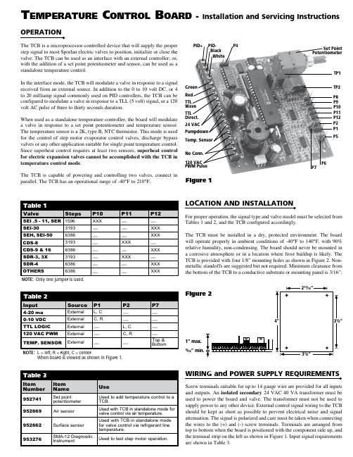
OPERATIONThe TCB is a microprocessor-controlled device that will supply the properstep signal to most Sporlan electric valves to position, initialize or close thevalve. The TCB can be used as an interface with an external controller; or,with the addition of a set point potentiometer and sensor, can be used as astandalone temperature control.In the interface mode, the TCB will modulate a valve in response to a signalreceived from an external source. In addition to the 0 to 10 volt DC, or 4to 20 milliamp signal commonly used on PID controllers, the TCB can beconfigured to modulate a valve in response to a TLL (5 volt) signal, or a 120volt AC pulse of three to thirty seconds duration.When used as a standalone temperature controller, the board will modulatea valve in response to a set point potentiometer and temperature sensor.The temperature sensor is a 2K, type B, NTC thermistor. This mode is usedfor the control of step motor evaporator control valves, discharge bypassvalves or any other application suitable for single point temperature control.Since superheat control requires at least two sensors, superheat controlfor electric expansion valves cannot be accomplished with the TCB intemperature control mode.The TCB is capable of powering and controlling two valves, connect inparallel. The TCB has an operational range of -40°F to 210°F.For proper operation, the signal type and valve model must be selected fromTables 1 and 2, and the TCB configured accordingly.The TCB must be installed in a dry, protected environment. The boardwill operate properly in ambient conditions of -40°F to 140°F, with 90%relative humidity, non-condensing. The board should never be mounted ina corrosive atmosphere or in a location where frost buildup is likely. TheTCB is provided with four 1/8” mounting holes as shown in Figure 2. Non-metallic standoffs are suggested but not required. Minimum clearance fromthe bottom of the TCB to a conductive substrate or mounting panel is 3/16”.WIRING and POWER SUPPLY REQUIREMENTSScrew terminals suitable for up to 14 gauge wire are provided for all inputsand outputs. An isolated secondary 24 VAC 40 VA transformer must beused to power the board and valve. The transformer must not be used tosupply power to any other device. External control signal wiring to the TCBshould be kept as short as possible to prevent electrical noise and signalattenuation. The signal is polarized and care must be taken when connectingthe wires to the (+) and (-) screw terminals. Terminals are arranged fromtop to bottom when the board is positioned with the component side up, andthe terminal strip on the left as shown in Figure 1. Input signal requirementsare shown in Table 3.T emperaTure C onTrol B oard - Installation and Servicing Instructions1” max.3/16” min.Figure 2NOTE: Only one jumper is used.NOTE: L = left, R = right, C = centerWhen board is viewed as shown in Figure 1.fdeREPLACEMENT PARTS AND PARTS KITSThere are no user serviceable parts on the TCB, however, the accessories listed in Table 3 aid in the use and testing of the TCB/electric valve system.TROUBLESHOOTINGIf a step motor is suspected to have failed, a simple resistance check may be made of the motor windings, however, actual winding failures are rare. Therefore Sporlan developed a diagnostic instrument, the SMA-12, to test our step motors. The SMA-12 is a step motor actuator that will operate all 12 volt DC bipolar step motor valves, as well as test the continuity of the valve wiring and motor. The step rate can be selected at 1, 50, 100 or 200 steps-per-second. At the one step-per-second rate the SMA-12 will test the continuity of the valve wiring and motor. The SMA-12 can also be used to manually open, position, or shut the valve should the controller fail. If contaminants are suspected, the SMA-12 can be used to drive the valve fully open to purge the foreign material.NOTE: Pin 8 causes valve to open on temperature rise above set point. Pin 9 causes valve to close on temperature rise above set point.4-20 MILLIAMP - source controller must supply 20 milliamps at 12volts DC into a 600 Ohm load.NOTE: 20 milliamps at 24 volt DC is not suitable. 0-10 VOLT - signal must be supplied with at least 20 milliampcurrent. Wiring between controller and TCB must be kept short to minimize electrical noise.TTL - logical “1” must be a DC signal greater than 4.5volts for 3 milliseconds. Logical “0” must be less than 0.5 volts DC for 3 milliseconds.AC PULSE - Must be 120 volts AC ± 20% for a period of 3 to30 seconds.INPUT SIGNAL REQUIREMENTS50000010000200003000040000-6010080604020-20-40120200180160140Temperature (Degrees Fahrenheit)O h m sFigure 3TEMPERATURE SENSOR RESISTANCEWhen a system component does fail, it is important to first determine whether the failure is the valve, the TCB, or the external controller (if used).TEST THE VALVEThe resistance of the motor winding may be tested without opening the system.1. Remove power from the external controller and/or TCB.2. Remove the valve leads from TCB.3. Measure the resistance between the black and white leads of the valve. The resistance should be 75 Ohms for brass housed valves with the valve at room temperature or about 65 Ohms if the valve is at -40ºF. The resis-tance for stainless steel housed valves should be 100 Ohms with the valve at room temperature.4. Measure the resistance between the green and red leads. This value should be within ± 5% of the resistance between the black and white leads.5. Measure the resistance from any lead to valve body. Resistance should be infinite, that is to say, open.TEST THE TCBThe flow charts that follow are designed to assist in diagnosing a possible TCB failure. All measurements should be made with a Digital Multimeter .Boards manufactured after March 1, 2000 will have a pin jumper on both P5 and P6. The boards are shipped with the jumpers on one post of P5 & P6. With the pin jumpers in this position, the valve will close when the pumpdown relay is energized. If both P5 & P6 are enabled, the valve will open when the pumpdown relay is energized.For testing purposes, make sure the pin jumpers are on both posts of pins P5 & P6.Look at the date on the serial number label in the center of the board. If the date is prior to March 1, 2000, continue with steps 9 through 13. If the date is March 1, 2000 or later, go to step 14 and continue.TROUBLE SHOOTING GUIDE – TCB Operating on External Signal (4-20 ma or 0-10 VDC)*Note: Before testing the TCB, make certain the valve is operating. See “Test the Valve” instructions.Boards manufactured after March 1, 2000 will have a pin jumper on both P5 and P6. The boards are shipped with the jumpers on one post of P5 & P6. With the pin jumpers in this position, the valve will close when the pumpdown relay is energized. If both P5 & P6 are enabled, the valve will open when the pumpdown relay is energized.For testing purposes, make sure the pin jumpers are on both posts of pins P5 & P6.Look at the date on the serial number label in the center of the board. If the date is prior to March 1, 2000, continue with steps 9 TROUBLE SHOOTING GUIDE – TCB Operating as Standalone ControllerNote: Before testing the TCB, make certain the valve is operating. See “Test the Valve” instructions.。
RPCE07三位元方向控制阀说明书
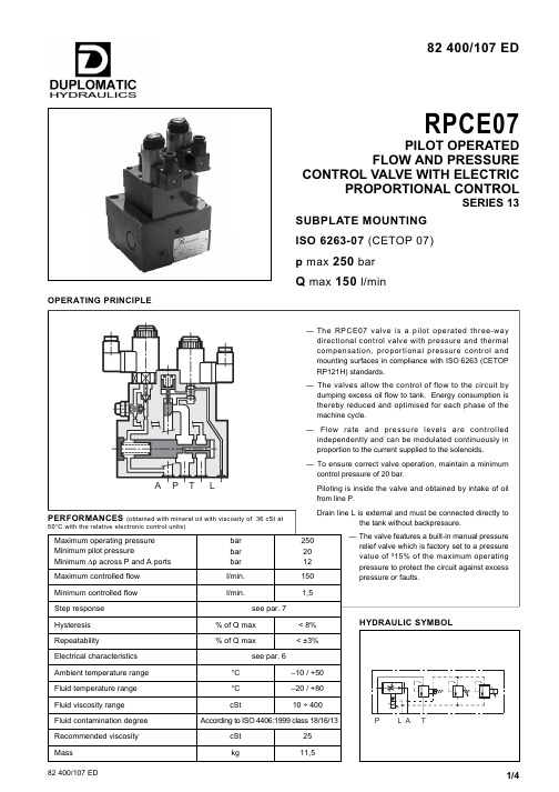
82 400/107 EDRPCE07PILOT OPERATEDFLOW AND PRESSURECONTROL VALVE WITH ELECTRICPROPORTIONAL CONTROLSERIES 13SUBPLATE MOUNTINGISO 6263-07 (CETOP 07)p max250barQ max150l/minOPERATING PRINCIPLE1 - IDENTIFICATION CODESeries No. (from 10 to 19 sizes andmounting dimensions remain unchanged)Pressure control range4= up to 140 bar 5= up to 250 barElectric proportional pressure control3-waycompensated flow control valveElectric proportional flow rate controlSize ISO 6263-07 (CETOP 07)2 - CHARACTERISTIC CURVES (measured with viscosity of 36 cSt at 50°C and UEIK-11 electronic control unit )RP C E 07-D/13Seal: omit for mineral oils V = viton for special fluids -24/Nominal solenoid voltage 24 V DC50100150200400200Q [l/min]I [mA]600800850100300500700FLOW CONTROL Q=f (I)Typical curve of flow control P →A according to current supplied to the solenoid.050100150200400250I [mA]600750100300500700p [bar]200PRESSURE CONTROL p=f (I)PRESSURE DROP ∆p=f(Q); FLOW P →TNOTE: The valve is preset at factory with a maximum current to the proportional solenoid of 750mA, to control the pressure.This setting must not exceeds the 750ma value.3 - PRESSURE COMPENSATIONThe valves are equipped with two restrictors in series. The first is an opening which can be adjusted by the proportional solenoid; the second, controlled by the pressure upstream and downstream of the first restrictor ensures constant pressure drop across the adjustable restrictor.In these conditions, the set flow rate value is maintained constant within a tolerance limit of ± 3% of the full scale flow rate for maximum pressure variation between the valve inlet and outlet chambers.4 - THERMAL COMPENSATIONA temperature-sensitive device installed on the flow control element of the valve corrects the position to maintain the set flow rate virtually unchanged, also in the case of fluid viscosity variation.Flow rate variation is therefore maintained within ± 2,5% of the set flow rate.Curve obtained with port A closed, zero current to the pressure control proportional solenoid and maximum current to the flow control proportional solenoid.Curve obtained with zero current to both the proportionalsolenoids.6 - ELECTRICAL CHARACTERISTICS7 - STEP RESPONSE (with mineral oil with viscosity of 36 cSt at 50°C inconjunction with the relative electronic control unit)8 - INSTALLATIONProportional solenoidThe proportional solenoid comprises two parts: tube and coil.The tube, screwed to the valve body, contains the armature which is designed to maintain friction to a minimum thereby reducing hysteresis.The coil is mounted on the tube secured by means of a lock nut and can be rotated through 360° depending on installation clearances.7.1 - Flow step responseStep response is the time taken for the valve to reach 90% of the set pressure value following a step change of reference signal.The table shows typical response times with an inlet flow of 100l/min and a backpressure of 50 bar on the A port.7.2 - Pressure step responseStep response is the time taken for the valve to reach 90% of the set pressure value following a step change of reference signal.The table shows typical response times with a flow of 50 l/min and the A port closed.The RPCE07 valve can be installed in any position without impairing correct operation.Ensure that there is no air in the hydraulic circuit. In particular applications, it can be necessary to vent the air entrapped in the solenoid tube, by using the apposite drain screw in the solenoid tube. Ensure that the solenoid tube is always filled with oil (see par.9). At the end of the operation, make sure of having screwed correctly the drain screw.Connect the L port on the valve directly to the tank without backpressure.5 - HYDRAULIC FLUIDSUse mineral oil-based hydraulic fluids HL or HM type, according to ISO 6743-4. For these fluids, use NBR seals.For fluids HFDR type (phosphate esters) use FPM seals (code V).For the use of other fluid types such as HFA, HFB, HFC, please consult our technical department.Using fluids at temperatures higher than 80 °C causes a faster degradation of the fluid and of the seals characteristics.The fluid must be preserved in its physical and chemical characteristics.Valves are fixed by means of screws or tie rods on a flat surface with planarity and/or roughness equal to or better than those indicated in the relative symbols. If minimum values are not observed fluid can easily leak between the valve and support surface.10 - ELECTRONIC CONTROL UNITS(valid for both flow rate and pressure controls)RPCE07SERIES 139 - OVERALL AND MOUNTING DIMENSIONSDUPLOMATIC OLEODINAMICA SpA20025 LEGNANO (MI) - P.le Bozzi, 1 / Via Edison Tel. 0331/472111-472236 - Fax 0331/548328。
MVP3300系列阀门定位器说明书
MVP智能电气阀门定位器3300系列用户手册1用户须知 (1)1.1安全指示 (1)1.2开箱清单 (1)1.3重要信息提示 (1)2概述 (1)2.1功能介绍 (2)2.2特点 (2)3技术参数 (2)4安装说明 (3)4.1外形尺寸 (3)4.2机构安装 (4)4.3气路连接 (7)4.4电气连接 (7)5调节操作 (9)5.1操作界面说明 (9)5.2用户菜单 (10)5.3初始化 (12)5.4诊断 (14)5.5报警 (14)5.6参数列表 (16)6参数解释 (17)7使用异常与维护保养 (20)7.1异常状况排除 (20)7.2维护保养 (21)8运输和贮存 (21)9订货须知 (22)9.1产品型号 (22)9.2其它可选项 (22)1用户须知1.1安全指示定位器先上电,后供气源;产品使用过程中,不要随意的触摸反馈连接装置;产品必须正确安装、正确操作和正确维护。
1.2开箱清单MVP智能阀门定位器;安装配件;用户手册;另外订制附件,详见装箱清单。
1.3重要信息提示为了您能更好地应用这份说明,以及保障你在调试,运行和维修这台仪器时的安全,请注意下列符号的用途:符号标语解说注意注意注意指潜在的危险,如不能避免,可能会损害产品本身或周围物体。
(危险物)提示提示提示是指有用的或特别的被忽视的能影响操作条件或产品功能的事物。
(不包含危险的或有害的情形)在安装和调试前请认真阅读此手册。
2概述MVP智能阀门定位器为深圳万讯自控有限公司推出的智能型两线制现场仪表。
本定位器作为气动阀门的配套控制部件,广泛运用于石油、化工、电力、冶金、轻工等领域的自动控制系统中。
MVP智能阀门定位器接受来自控制系统的4~20mA阀位设定信号,通过A/D转换得到阀位设定值;同时通过位置传感器得到实际的阀位信号;两者经过控制软件的计算处理,从而控制气动执行机构的进气与排气,驱动阀位到达设定点(如图1所示)MVP智能阀门定位器是基于微处理器技术的高性能电/气阀门定位器,能很好地克服摩擦力和阀芯上的不平衡力,提高调节阀的响应速度,使其定位迅速准确。
阀门电动装置说明书
1.概述多回转阀门电动装置,简称为Z型电装,是阀门实现开启、关闭或调节控制的驱动设备。
Z型电装适用于闸阀、截止阀、隔膜阀、柱塞阀、节流阀、水闸门等。
可用于明杆阀,也可用于暗杆阀。
本系列电装具有功能全、性能可靠、控制系统先进、体积小、重量轻、使用维护方便等特点。
可对阀门实行远控、集控和自动控制。
广泛用于电力、冶金、石油、化工、造纸、污水处理等行业。
本产品的性能符合JB/T8528-1997《普通型阀门电动装置技术条件》的规定。
隔爆型的性能符合GB3836.1-2000《爆炸性气体环境用电气设备第1部分:通用要求》,GB3836.2-2000《爆炸性气体环境用电气设备第2部分:隔爆型“d”》及JB/T8529-1997《隔爆型阀门电动装置技术条件》的规定。
多回转电动装置按防护类型分:有户外型和隔爆型;按控制方式分:有常规型、整体型和整体调节型;按连接型式分:有转矩型、电站型和推力型。
2.型号表示方法A:带现场按钮;F:带4-20mA信号输出;S:带手动减速箱输出轴最大转圈数:阿拉伯数字表示,无数字见表1输出转速:阿拉伯数字表示,单位r/min(转/分)连接型式:T表示推力型,I表示电站型,无代号为常规转矩型额定输出转矩:阿拉伯数字表示,单位kgf·mZ:整体型;TZ:整体调节型防护类型:W表示户外型;B表示隔爆型产品型式:多回转电动装置型号示例:1.DZW30I-18/50:多回转电动装置,输出转矩300N·m(30kgf·m),电站型接口,输出转速18r/min,最大转圈数50,常规户外型。
2.DZBTZ45T-24B/S:多回转电动装置,输出转矩450N·m(45kgf·m),推力型接口,输出转速24 r/min,最大转圈数120,整体调节隔爆型,带手动减速箱。
3.DZZ120-24/240:多回转电动装置,输出转矩1200N·m (120kgf·m),转矩型接口,输出转速24 r/min,最大转圈数240圈,整体型。
MK系列空气阀门控制值用户操作和维护指南说明书
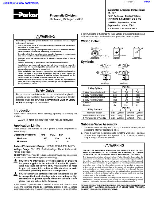
3/2With Regulator 3/24/2With Regulator4/2Installation & Service Instructions: V671BP“MK” Series Air Control Valves 1/8" Inline & Subbase, 3/2 & 4/2ISSUED: September, 2006 Supersedes: June, 2001DOC.# V-671P, ECN# 060870 Rev. 3Pneumatic DivisionRichland, Michigan 49083IntroductionFollow these instructions when installing, operating or servicing the product.VALVE IS NOT DESIGNED FOR FIELD SERVICEApplication LimitsThese products are intended for use in general purpose compressed air systems only.Operating Pressure: kPa PSIG barMaximum 827 120 8.27MinimumAmbient Temperature Range: -15°C to 60°C (5°F to 140°F)Voltage Range: 85-110% of rated voltage. These limits should not be exceeded.EXCEPTION: The 47 and 48 voltage code rated Valves may be operated at 70-125% of the rated voltage (3/2 valves only).CAUTION: An interruption of 10 milliseconds or greater to the power supplied to the solenoid of a solenoid operated valve may cause the valve to shift. Provision must be made to prevent power interruption of this duration to avoid unintended, potentially hazardous, consequences.CAUTION: This valve contains solid state components that can be damaged by transient voltage spikes, over-voltage or high temperature. To protect against premature solenoid failure, please read and adhere to the following:If this solenoid operated valve is used in a circuit with other inductive loads, the solenoid should be electrically protected with a voltage suppression device (e.g. transient voltage suppressor or varistor) that hasa minimum rating of 1.6 times the rated voltage of the solenoid valve and sufficient capacity to dissipate the energy of other inductive loads.Wiring DetailSymbols3-Way OptionsPort No.1 2 3 3-Way, Normally Closed Inlet Cyl Exh 3-Way, Normally Open Exh Cyl Inlet 2-Way, Normally Closed Inlet Cyl Plug 2-Way, Normally Open Plug Cyl Inlet Selector Inlet Cyl Inlet DiverterCyl InletCyl 4-Way OptionsPort No.1 2 3 4 Normal FunctionInlet Cylinder Exhaust Cylinder 4-Way used as 3-Way, NC Inlet Plug Exhaust Cylinder4-Way used as 3-Way, NOInlet Cylinder ExhaustPlugSubbase Valve Assembly1. Install the Selector Plate (Item 2) on top of the manifold and push theprojections into their appropriate holes.2. Place the valve on the selector plate. Install the two Socket Head CapScrews (Item 1) provided and tighten to .7 to 1.1 Nm (6 to 10 in-lb) torque using a 2.5mm hex wrench.WARNING To avoid unpredictable system behavior that can cause personal injuryand property damage:• Disconnect electrical supply (when necessary) before installation, servicing, or conversion.• Disconnect air supply and depressurize all air lines connected to this product before installation, servicing, or conversion.• Operate within the manufacturer’s specified pressure, temperature, and other conditions listed in these instructions.• Medium must be moisture-free if ambient temperature is below freezing.• Service according to procedures listed in these instructions.• Installation, service, and conversion of these products must be performed by knowledgeable personnel who understand how pneumatic products are to be applied.• After installation, servicing, or conversion, air and electrical supplies (when necessary) should be connected and the product tested for proper function and leakage. If audible leakage is present, or the product does not operate properly, do not put into use.• Warnings and specifications on the product should not be covered by paint, etc. If masking is not possible, contact your local representative for replacement labels.!WARNINGFAILURE OR IMPROPER SELECTION OR IMPROPER USE OF THEPRODUCTS AND/OR SYSTEMS DESCRIBED HEREIN OR RELATED ITEMS CAN CAUSE DEATH, PERSONAL INJURY AND PROPERTY DAMAGE.This document and other information from Parker Hannifin Corporation, its subsidiaries and authorized distributors provide product and/or system options for further investigation by users having technical expertise. It is important that you analyze all aspects of your application, including consequences of any failure and review the information concerning the product or systems in the current product catalog. Due to the variety of operating conditions and applications for these products or systems, the user, through its own analysis and testing, is solely responsible for making the final selection of the products and systems and assuring that all performance, safety and warning requirements of the application are met.The products described herein, including without limitation, product features, specifications, designs, availability and pricing, are subject to change by Parker Hannifin Corporation and its subsidiaries at any time without notice.EXTRA COPIES OF THESE INSTRUCTIONS ARE AVAILABLE FOR INCLUSION IN EQUIPMENT / MAINTENANCE MANUALS THAT UTILIZE THESE PRODUCTS. CONTACT YOUR LOCAL REPRESENTATIVE.!Safety GuideFor more complete information on recommended application guidelines, see the Safety Guide section of Pneumatic Division catalogs or you can download the Pneumatic Division Safety Guide at: /safety!!(11-18-2011)INDEXClick here to view bookmarks.3. When DIN Rail Mounting Bracket is provided: install Screws(Item 9) through the Manifold and secure the DIN Rail Connecting Bracket (Item 10) on both ends of the Manifold.4. When Regulator Kit is provided: Install the two O-rings provided(Item 3) into the slots on the Regulator Housing (Item 4). Install the Regulator Housing (Item 4) using the two Mounting Screws (Item 5) and tighten to .7 to 1.1 Nm (6 to 10 in-lb) torque using a 2.5mm hex wrench. Install the Regulator (Item 6) into the Housing (Item 4) and torque to1.7 to 2.3 Nm (15 to 20 in-lb).5. When Gauge Kit is provided: Install the appropriate Pipe Fitting(Item 8) into the Regulator Housing (Item 4) Install the Gauge (Item 7) on to the Pipe Fitting.6. T est valve for functional operation and for internal and external leakage. If leakage is audible (likely indicating improper assembly) do not operate – conduct assembly again.If in-service lubricant is used, F442 oil is recommended. F442 is specially formulated to promote maximum service life of air operated equipment. Other compatible lubricants should be of straight paraffin base mineral oil having a viscosity of 100-200 SSU @ 100°F and an Aniline Point greater than 200°F . CAUTION: Do not use synthetic, reconstituted, or oils with alcohol content or detergent additives.Subbase Kits AvailableKit No. Description PS2105P ....................................................3/2 NC Selector Plate Kit PS2106P ...................................................3/2 NO Selector Plate Kit PS2109P ...............................................Regulator Blanking Plate Kit PS2131122P ........................Regulator Kit Without Gauge, 2-60 PSI PS2131133P ......................Regulator Kit Without Gauge, 5-125 PSI PS2131155P .............................Regulator Kit With Gauge, 2-60 PSI PS2131166P ...........................Regulator Kit With Gauge, 5-125 PSI PS2188P ...................................................Valve to Subbase Bolt Kit PS2194P ..........................................3/2 Subbase Blanking Plate Kit PS219401P ......................................4/2 Subbase Blanking Plate Kit PS2195P ..............................................10-32 Extension Kit (10 / Kit)PS2196P ..................................................Swivel Adapter Kit (5 / Kit)Instructions for Converting NC to NO - 3/2 Valves OnlySelector Plates (Item 2) can be changed to convert function. Remove the Valve Body Assembly from the Base by removing the two Body / Manifold Screws (Item 1). Remove the existing Selector Plate (Item 2). Place the new Selector Plate with the appropriate function on the Subbase. The function can be read on this Selector Plate when viewed from the side opposite the Solenoid. Replace the Valve Assembly on the Selector Plate. Reinstall the two Screws (Item 1) and tighten .7 to 1.1 Nm (6 to 10 in-lb) torque. Turn on air pressure and electrical powersource. Test valve for proper functional operation and for internal and external leakage.Inline Valve on Inlet / Exhaust Manifold Assembly1. Install two of the four O-rings (Item 12) in the counterbores on top ofthe Manifold.2. Place the Valve on the Manifold. For normally closed operation(3/2 Valves), line up the Solenoid end of the Valve with the Port 1 on the Manifold. For normally open operation (3/2 valves only), line up the Solenoid end of the Valve with the Port 3 on the manifold. Install the two Socket Head Cap Screws (Item 11) provided and tighten to 1.5 to 1.9 Nm (13 to 17 in-lb) torque using a 2.5mm hex wrench. For 4/2 valves, the Solenoid end on the Valve must always line up with Port 1 of the Manifold.3. When DIN Rail Mounting Bracket is provided, install Screws (Item 14)through the Manifold and secure the DIN Rail Connecting Bracket (Item 10) on both ends of the Manifold.4. When Sandwich Regulator Kit is provided: Install the Sandwich (Item15) on top of the Manifold (Item 13). Line up Port 1 on the Manifold with the Regulator end of the Sandwich. Install the remaining two of the four O-rings provided (Item 12) into the slots on top of the Sandwich. Install the two Mounting Screws (Item 11) and tighten to 1.5 to 1.9 Nm (13 to 17 in-lb) torque using a 2.5mm hex wrench. The 3-Way valve can be oriented as described in paragraph (2) for NO or NC operation. Install the Regulator (Item 6) into the Sandwich (Item 15) and torque to1.7 to 2.3 Nm (15 to 20 in-lb).5. When Gauge is provided: Install the Gauge (Item 7) directly intothe Sandwich Regulator Housing (Item 15), or install Pipe Nipples (Item 8) (Items not shown) to Gauge port then to Gauge. Gauge diameter is larger than Regulator width, so Gauge mounting must be staggered.6. Test valve for functional operation and for internal and externalleakage. If leakage is audible (most likely indicating improper assembly) do not operate – conduct assembly again.7. When Selector Sandwich is required, install similar to Item 15. TheSelector Sandwich allows selective isolation of either the inlet or exhaust or both, when Sandwich is between valve and IEM.IEM Kits AvailableKit No. DescriptionPS2130122P .............................Regulator Kit Without Gauge, 2-60 PSI PS2130133P ...........................Regulator Kit Without Gauge, 5-125 PSI PS2130155P ..................................Regulator Kit With Gauge, 2-60 PSI PS2130166P ................................Regulator Kit With Gauge, 5-125 PSI PS2144P ..............................................................Selector Sandwich Kit PS2166P .........................3/2 or 4/2 IEM NPT Ported Blanking Plate Kit PS2169P .............................................3/2 or 4/2 IEM Blanking Plate Kit PS2184P ............................3/2 or 4/2 Valve to IEM O-Ring Kit (10 / Kit)PS2187P ..................................3/2 or 4/2 Valve to IEM Bolt Kit (10 / Kit)PS2190P ....................................Din Rail Mounting Kit, Subbase & IEM!“MK” Series Air Control Valves 1/8" Inline & Subbase , 3/2 & 4/2 V-671BPShownPneumatic DivisionRichland, Michigan 49083 269-629-5000PDNSG-1Safety Guide For Selecting And Using Pneumatic Division Products And Related AccessoriesWARNING:FAILURE OR IMPROPER SELECTION OR IMPROPER USE OF PNEUMATIC DIVISION PRODUCTS, ASSEMBLIES OR RELATED ITEMS (“PRODUCTS”) CAN CAUSE DEATH, PERSONAL INJURY, AND PROPERTY DAMAGE. POSSIBLE CONSEQUENCES OF FAILURE OR IMPROPER SELECTION OR IMPROPER USE OF THESE PRODUCTS INCLUDE BUT ARE NOT LIMITED TO:• Unintended or mistimed cycling or motion of machine members or failure to cycle • Work pieces or component parts being thrown off at high speeds.• Failure of a device to function properly for example, failure to clamp or unclamp an associated item or device.• Explosion• Suddenly moving or falling objects.• Release of toxic or otherwise injurious liquids or gasses.Before selecting or using any of these Products, it is important that you read and follow the instructions below.1. GENERAL INSTRUCTIONS1.1. Scope: This safety guide is designed to cover general guidelines on the installation, use, and maintenance of Pneumatic Division Valves, FRLs (Filters, Pressure Regulators, and Lubricators), Vacuum products and related accessory components.1.2. Fail-Safe: Valves, FRLs, Vacuum products and their related components can and do fail without warning for many reasons. Design all systems and equipment in a fail-safe mode, so that failure of associated valves, FRLs or Vacuum products will not endanger persons or property.1.3 Relevant International Standards: For a good guide to the application of a broad spectrum of pneumatic fluid power devices see: ISO 4414:1998, Pneumatic Fluid Power – General Rules Relating to Systems. See for ordering information.1.4. Distribution: Provide a copy of this safety guide to each person that is responsible for selection, installation, or use of Valves, FRLs or Vacuum products. Do not select, or use Parker valves, FRLs or vacuum products without thoroughly reading and understanding this safety guide as well as the specific Parker publications for the products considered or selected.1.5. User Responsibility: Due to the wide variety of operating conditions and applications for valves, FRLs, and vacuum products Parker and its distributors do not represent or warrant that any particular valve, FRL or vacuum product is suitable for any specific end use system. This safety guide does not analyze all technical parameters that must be considered in selecting a product. The user, through its own analysis and testing, is solely responsible for: • Making the final selection of the appropriate valve, FRL, Vacuum component, or accessory. • Assuring that all user’s performance, endurance, maintenance, safety, and warning requirements are met and that the application presents no health or safety hazards. • Complying with all existing warning labels and / or providing all appropriate health and safety warnings on the equipment on which the valves, FRLs or Vacuum products are used; and, • Assuring compliance with all applicable government and industry standards. 1.6. Safety Devices: Safety devices should not be removed, or defeated.1.7. Warning Labels: Warning labels should not be removed, painted over or otherwise obscured.1.8. Additional Questions: Call the appropriate Parker technical service department if you have any questions or require any additional information. See the Parker publication for the product being considered or used, or call 1-800-CPARKER, or go to , for telephone numbers of the appropriate technical service department.2. PRODUCT SELECTION INSTRUCTIONS2.1. Flow Rate: The flow rate requirements of a system are frequently the primary consideration when designing any pneumatic system. System components need to be able to provide adequate flow and pressure for the desired application.2.2. Pressure Rating: Never exceed the rated pressure of a product. Consult product labeling, Pneumatic Division catalogs or the instruction sheets supplied for maximum pressure ratings.2.3. Temperature Rating: Never exceed the temperature rating of a product. Excessive heat can shorten the life expectancy of a product and result in complete product failure.2.4. Environment: Many environmental conditions can affect the integrity and suitability of a product for a given application. Pneumatic Division products are designed for use in general purpose industrial applications. If these products are to be used in unusual circumstances such as direct sunlight and/or corrosive or caustic environments, such use can shorten the useful life and lead to premature failure of a product.2.5. Lubrication and Compressor Carryover: Some modern synthetic oils can and will attack nitrile seals. If there is any possibility of synthetic oils or greases migrating into the pneumatic components check for compatibility with the seal materials used. Consult the factory or product literature for materials of construction.2.6. Polycarbonate Bowls and Sight Glasses: To avoid potential polycarbonate bowl failures: • Do not locate polycarbonate bowls or sight glasses in areas where they could be subject to direct sunlight, impact blow, or temperatures outside of the rated range. • Do not expose or clean polycarbonate bowls with detergents, chlorinated hydro-carbons, keytones, esters or certain alcohols. • Do not use polycarbonate bowls or sight glasses in air systems where compressors are lubricated with fire resistant fluids such as phosphate ester and di-ester lubricants.!PDNSG-1Pneumatic Division Safety Guide ISSUED: August 1 , 2006Supersedes: June 1, 2006Pneumatic Division Safety Guide2.7. Chemical Compatibility: For more information on plastic component chemical compatibility see Pneumatic Division technical bulletinsTec-3, Tec-4, and Tec-52.8. Product Rupture: Product rupture can cause death, serious personal injury, and property damage.• Do not connect pressure regulators or other Pneumatic Division products to bottled gas cylinders.• Do not exceed the maximum primary pressure rating of any pressure regulator or any system component.• Consult product labeling or product literature for pressure rating limitations.3. PRODUCT ASSEMBLY AND INSTALLATION INSTRUCTIONS3.1. Component Inspection: Prior to assembly or installation a careful examination of the valves, FRLs or vacuum products must beperformed. All components must be checked for correct style, size, and catalog number. DO NOT use any component that displays any signs of nonconformance.3.2. Installation Instructions: Parker published Installation Instructions must be followed for installation of Parker valves, FRLs andvacuum components. These instructions are provided with every Parker valve or FRL sold, or by calling 1-800-CPARKER, or at.3.3. Air Supply: The air supply or control medium supplied to Valves, FRLs and Vacuum components must be moisture-free if ambienttemperature can drop below freezing4. VALVE AND FRL MAINTENANCE AND REPLACEMENT INSTRUCTIONS4.1. Maintenance: Even with proper selection and installation, valve, FRL and vacuum products service life may be significantly reducedwithout a continuing maintenance program. The severity of the application, risk potential from a component failure, and experience with any known failures in the application or in similar applications should determine the frequency of inspections and the servicing or replacement of Pneumatic Division products so that products are replaced before any failure occurs. A maintenance program must be established and followed by the user and, at minimum, must include instructions 4.2 through 4.10.4.2. Installation and Service Instructions: Before attempting to service or replace any worn or damaged parts consult the appropriateService Bulletin for the valve or FRL in question for the appropriate practices to service the unit in question. These Service andInstallation Instructions are provided with every Parker valve and FRL sold, or are available by calling 1-800-CPARKER, or by accessing the Parker web site at .4.3. Lockout / Tagout Procedures: Be sure to follow all required lockout and tagout procedures when servicing equipment. For moreinformation see: OSHA Standard – 29 CFR, Part 1910.147, Appendix A, The Control of Hazardous Energy – (Lockout / Tagout)4.4. Visual Inspection: Any of the following conditions requires immediate system shut down and replacement of worn or damagedcomponents:• Air leakage: Look and listen to see if there are any signs of visual damage to any of the components in the system. Leakage is an indication of worn or damaged components.• Damaged or degraded components: Look to see if there are any visible signs of wear or component degradation.• Kinked, crushed, or damaged hoses. Kinked hoses can result in restricted air flow and lead to unpredictable system behavior.• Any observed improper system or component function: Immediately shut down the system and correct malfunction.• Excessive dirt build-up: Dirt and clutter can mask potentially hazardous situations.Caution: Leak detection solutions should be rinsed off after use.4.5. Routine Maintenance Issues:• Remove excessive dirt, grime and clutter from work areas.• Make sure all required guards and shields are in place.4.6. Functional Test: Before initiating automatic operation, operate the system manually to make sure all required functions operateproperly and safely.4.7. Service or Replacement Intervals: It is the user’s responsibility to establish appropriate service intervals. Valves, FRLs and vacuumproducts contain components that age, harden, wear, and otherwise deteriorate over time. Environmental conditions can significantly accelerate this process. Valves, FRLs and vacuum components need to be serviced or replaced on routine intervals. Service intervals need to be established based on:• Previous performance experiences.• Government and / or industrial standards.• When failures could result in unacceptable down time, equipment damage or personal injury risk.4.8. Servicing or Replacing of any Worn or Damaged Parts: To avoid unpredictable system behavior that can cause death, personalinjury and property damage:• Follow all government, state and local safety and servicing practices prior to service including but not limited to all OSHA Lockout Tagout procedures (OSHA Standard – 29 CFR, Part 1910.147, Appendix A, The Control of Hazardous Energy – Lockout / Tagout).• Disconnect electrical supply (when necessary) before installation, servicing, or conversion.• Disconnect air supply and depressurize all air lines connected to system and Pneumatic Division products before installation, service, or conversion.• Installation, servicing, and / or conversion of these products must be performed by knowledgeable personnel who understand how pneumatic products are to be applied.• After installation, servicing, or conversions air and electrical supplies (when necessary) should be connected and the product tested for proper function and leakage. If audible leakage is present, or if the product does not operate properly, do not put product orsystem into use.• Warnings and specifications on the product should not be covered or painted over. If masking is not possible, contact your localrepresentative for replacement labels.4.9. Putting Serviced System Back into Operation: Follow the guidelines above and all relevant Installation and Maintenance Instructionssupplied with the valve FRL or vacuum component to insure proper function of the system.。
MA3系列水力阀门 Mill Type 圆线阀门操作指南说明书

MANUAL2Parker HannifinCylinder Division EuropeManual'Mill Type' CylindersMA3 SeriesHydraulic Cylinder Operating InstructionsFitting and commissioning is to be carried out by qualified personnel only, in accordance with the operating instructions.1. Mounting and connections1.1 Mounting of actuator depends on the options selected: – Flange – Pivot– Foot1.2 Hydraulic ports are in each end cap.1.3 Connecting the load: use the mounting thread on the piston rod.1.4 Cushion adjusting screws are fitted in the head and/ or cap, where specified.1.5 Air bleed screws are fitted in the head and/or cap, where specified.1.6 Stroke adjusters are fitted in end caps, where specified.1.7 Electrical connector for transducer, where specified.2. FunctionPressurized fluid is applied to a circular piston inside a cylinder which pushes the rod. This action moves the piston genera-ting linear motion. This linear motion and force is transmitted to the application by the rod. Where specified, the sensor provides a signal which indicates stroke position. This signal may be analogue or digital.3. General conditions of useThese general recommendations for the correct and safe use of the product must be observed at all times:– Comply with the limits specified in the catalogue. – Ensure the hydraulic fluid supplied meets the specified cleanliness level. – Ensure the correct seal class has been specified for the hydraulic fluid used. – Ensure that the actuator is suitable for the prevailing ambient conditions. – Comply with the national and local safety laws and regulations. – Remove all transport packaging. All packaging material used is recyclable. – Maintain the fluid specified for the complete service life of the product.4. InstallationMechanical– Check that the cylinder model code meets the specification required.– Handle the cylinder with care in order to prevent damage to the cylinder tube and piston rod which could reduce reliability and safe operation.– Mount the cylinder so that all control elements are always accessible.– Mount the cylinder so that there is no misalignment between the rod and its mating fitting.– Tighten screws, lock nuts and accessories to the torques specified in the maintenance manual.Hydraulic – Tube and hose fittings are to be screwed directly into the pressure ports of the cylinder end caps. – Fill the cylinder slowly in order to preventuncontrolled movements.ElectricIf a sensor is fitted, ensure that the cable is not energized when attaching the cable to the sensor connector.5. Commissioning Complete SystemSlowly fill the complete hydraulic system with oil in order to prevent any uncontrolled movements. During the filling opera-tion, the system and/or cylinder must be bled of air at suitable points.Hydraulic Cylinder – Make sure that the area traversed by the rod and attached mass is clear of personnel or any obstructing bodies. – Start a test run.– If necessary adjust the cushion screw to achieve optimal performance. The purpose of the cushion adjustment is to ensure that the cylinder achieves full stroke without striking the cap too hard.– If fitted, use the stroke adjusters to achieve the stroke required. It is recommended that hydraulic pressure should be released before makingadjustments.– CAUTION : During all adjustments ensure that theoperator is clear of the area traversed by the moving mass.6. Operation6.1 Make sure that the area traversed by the moving mass is clear of personnel or any obstructing bodies. Only handle the cylinder when all movement has ceased.6.2 Ensure that the oil and ambient temperature is within the temperature range of the cylinder fitted.6.3 Make sure that the pressure indicated on the model plate is not exceeded.7. Maintenance7.1 The cylinder must be regularly checked for leaks. If seals are leaking they must be replaced according to the maintenance bulletins (see 9)7.2 Ensure the hydraulic fluid supplied meets the specified cleanliness level. Filtration to ISO Class 17/14.7.3 Ensure that all maintenance work is in compliance with the national environmental and safety regulations.7.4 Any further instructions, see maintenance bulletin referred to in 7.1.3Parker HannifinCylinder Division EuropeManual'Mill Type' CylindersMA3 SeriesWARNING – USER RESPONSIBILITYFAILURE OR IMPROPER SELECTION OR IMPROPER USE OF THE PRODUCTS DESCRIBED HEREIN OR RELATED ITEMS CAN CAUSE DEATH, PERSONAL INJURY AND PROPERTY DAMAGE.This document and other information from Parker-Hannifin Corporation, its subsidiaries and authorized distributors provide product or system options for further investigation by users having technical expertise.The user, through its own analysis and testing, is solely responsible for making the final selection of the system and components andassuring that all performance, endurance, maintenance, safety and warning requirements of the application are met. The user must analyze all aspects of the application, follow applicable industry standards, and follow the information concerning the product in the current product catalog and in any other materials provided from Parker or its subsidiaries or authorized distributors.To the extent that Parker or its subsidiaries or authorized distributors provide component or system options based upon data or speci-fications provided by the user, the user is responsible for determining that such data and specifications are suitable and sufficient for all applications and reasonably foreseeable uses of the components or systems.Offer of SalePlease contact your Parker representation for a detailed 'Offer of Sale'.8. Disassembly and Repairs8.1 For any further instructions see maintenance bulletin referred to in 7.1.8.2 Use original Parker spare parts only. For any further advice, please contact your nearest Parker Sales office.9. Corrective Actions10. Technical DataSee catalogue: MSG1910-0262Parker Hannifin Ltd. Tachbrook Park Drive Tachbrook Park, Warwick, CV34 6TU United KingdomTel.: +44 (0) 1926 317 Manual MA3Your local authorized Parker distributor© 2020 Parker Hannifin Corporation. All rights reserved.European Product Information Centre Free phone: 00 800 27 27 5374(from AT, BE, CH, CZ, DE, DK, EE, ES, FI, FR, IE, IL, IS, IT, LU, MT, NL, NO, PL, PT, RU, SE, SK, UK, ZA)Europe, Middle East, AfricaAE – United Arab Emirates, DubaiTel: +971 4 8127100AT – Austria, St. Florian Tel: +43 (0)7224 66201 AZ – Azerbaijan, Baku Tel: +994 50 2233 458BE/NL/LU – Benelux, Hendrik Ido Ambacht Tel: +31 (0)541 585 000BY – Belarus, Minsk Tel: +48 (0)22 573 24 00CH – Switzerland, Etoy Tel: +41 (0)21 821 87 00 CZ – Czech Republic, PragueTel: +420 284 083 111DE – Germany, Kaarst Tel: +49 (0)2131 4016 0DK – Denmark, Ballerup Tel: +45 43 56 04 00ES – Spain, Madrid Tel: +34 902 330 001FI – Finland, Vantaa Tel: +358 (0)20 753 2500FR – France, Contamine s/Arve Tel: +33 (0)4 50 25 80 25GR – GreeceTel: +30 69 44 52 78 25HU – Hungary, Budaörs Tel: +36 23 885 470IE – Ireland, Dublin Tel: +353 (0)1 466 6370IL – IsraelTel: +39 02 45 19 21IT – Italy, Corsico (MI) Tel: +39 02 45 19 21KZ – Kazakhstan, Almaty Tel: +7 7273 561 000NO – Norway, Asker Tel: +47 66 75 34 00PL – Poland, Warsaw Tel: +48 (0)22 573 24 00PT – PortugalTel: +351 22 999 7360RO – Romania, Bucharest Tel: +40 21 252 1382RU – Russia, Moscow Tel: +7 495 645-2156SE – Sweden, Borås Tel: +46 (0)8 59 79 50 00SL – Slovenia, Novo Mesto Tel: +386 7 337 6650TR – Turkey, Istanbul Tel: +90 216 4997081UK – United Kingdom, Warwick Tel: +44 (0)1926 317 878ZA – South Africa, Kempton Park Tel: +27 (0)11 961 0700North AmericaCA – Canada, Milton, Ontario Tel: +1 905 693 3000US – USA, Cleveland Tel: +1 216 896 3000Asia PacificAU – Australia, Castle Hill Tel: +61 (0)2-9634 7777CN – China, Shanghai Tel: +86 21 2899 5000HK – Hong Kong Tel: +852 2428 8008IN – India, MumbaiTel: +91 22 6513 7081-85JP – Japan, Tokyo Tel: +81 (0)3 6408 3901KR – South Korea, Seoul Tel: +82 2 559 0400MY – Malaysia, Shah Alam Tel: +60 3 7849 0800NZ – New Zealand, Mt Wellington Tel: +64 9 574 1744SG – Singapore Tel: +65 6887 6300TH – Thailand, Bangkok Tel: +662 186 7000TW – Taiwan, Taipei Tel: +886 2 2298 8987Parker WorldwideSouth AmericaAR – Argentina, Buenos Aires Tel: +54 3327 44 4129BR – Brazil, Sao Jose dos Campos Tel: +55 080 0727 5374CL – Chile, Santiago Tel: +56 22 303 9640MX – Mexico, TolucaTel: +52 72 2275 4200。
多功能阀中文操作手册

普罗名特® 多功能阀操 作 手 册P r o M i n e n t®目录1结构设计 (1)2功能描述 (1)3使用范围 (2)4安装 (3)5操作 (3)6技术参数和订货号 (4)1结构设计多功能阀通过弹簧负载的隔膜实现其每个功能。
阀的卸压机构具有保持压力恒定以及卸压的功能。
2功能描述功能- 敞口计量时,产生一个稳定的背压。
顺时针方向旋转黑色星状旋钮(1)可取消此项功能。
- 防止投加点产生负压时从药桶中抽出药液。
顺时针方向旋转黑色星状旋钮(1)可取消此项功能。
注意背压阀不能用作完全密封截止阀。
1 2如果不向投加点输送计量介质或泵的待机时间长,则必须在泵的吸入端另外安装截止阀。
- 启动泵时克服压力辅助引液,而不必松开排液管线。
旋动红色星状按钮(2)实现此项功能。
注意— 由于阀工作时,系统的药液可能通过旁路管线流出,故必须在投加点安装单向止回阀。
- 当相关系统处于待机状态(例如维修)时,用于给计量管线卸压。
- 用作溢流阀,防止由计量泵产生的不允许的超压。
通过旁路管线溢流,自动执行溢流功能。
3 使用范围指定用途用于在关闭截止阀时,防止因计量泵产生的不容许的超压。
必须连接旁路管线。
非指定用途不能用于防止除计量泵以外的其它原因产生的不容许的超压。
此阀不能用作截止阀。
如果压力系统没有安装注射阀,不能使用此阀。
如系统没有安装旁路溢流管线,不能使用此阀。
4安装安全注意事项投加点必须安装单向止回阀,因为阀工作时系统中的计量介质通过旁路可能会产生回流。
机械/液压安装多功能阀直接旋到泵的压力连接端上,阀可以360°任意转动。
使用连接用具或GF螺纹配件,将计量管线或软管固定在泵的出口端上。
出厂前,EPDM材质的O型圈已安装在泵出口的凹槽内。
对于不适用EPDM材质的情况,建议安装Viton B型的O型圈,该O型圈(棕色)同阀一起供货。
使用卡环和管接螺母紧固旁路管线,并引回药桶。
因为阀在接近于开启压力时会出现少量的溢流,故必须始终接通旁路管线。
(完整版)03KMX15R控制阀说明书0001

表 10
编 号
பைடு நூலகம்零件名称
数 量
备注
编 号
零件名称
数 量
备注
101
阀体
1
201
旋入套
1
力矩74N? m
161
O形圈
1
P22A
301
堵头
1
力矩34~39N? m
162
O形圈
3
P16
511
阀芯
1
163
O形圈
2
P7
512
弹簧
1
164
O形圈
1
P11
541
阀套
1
171
内六角螺钉
4
M6-50
(10)液压回路
图13
备注
编号
零件名称
数 量
备注
303
阀杆
1
353
堵头
1
力矩59~69N? m
表
表8
编号
零件名称
数 量
备注
编号
零件名称
数 量
备注
611
阀芯
1
632
套
1
621
弹簧
1
638
过滤件
1
631
弹簧座
1
表9
编号
零件名称
数 量
备注
编号
零件名称
数 量
备注
391
阀杆
1
340
弹簧
1
317
内阀芯3
1
352
堵头
1
力矩49~59N? m
流经U型通道,再到斗杆阀杆(302)。于是,液压油沿着斗杆阀杆(302)的外圈流向接口Ba1,然 后再供给斗杆油缸小腔(有杆腔R)。
智能阀门定位器YT 3400系列使用说明书
智能阀门定位器YT-3400系列使 用 说 明 书YTC V.1.04- 目 录(硬件)-说明书概要3安全注意事项和产品保证内容及保证期限3危险区域使用时注意事项3产品简介4主要特征和功能4铭牌内容和说明5型号标记方法6主要参数7内部结构8安装9注意事项9 YT-3400L 外形尺寸图9 YT-3400R 外形尺寸图10排水接头的位置调整10 YT-3400L的安装11 YT-3400L的安装例图 11利用支架安装YT-3400L11 YT-3400R的安装15 YT-3400R的安装例图15利用支架安装YT-3400R15气管连接18注意事项18使用的空压条件18接管的条件19执行机构和YT-3400气管的连接19单作用执行机构和气管的连接19双作用执行机构和气管的连接19电源连接20注意事项20电流输入信号端子的连接21反馈信号端子的连接21限位开关端子的连接22接地端子的连接22自动/手动开关23流量调节旋钮的使用方法23- 目 录 (软件)-自动设定和基本操作方法24按钮说明24正常运行模式(RUN模式)的说明25自动设定 (AUTO CAL)25自动设定1 (AUTO 1) 26自动设定2 (AUTO 2)26自动设定3 (AUTO 3) 26自动设定HF(AUTO HF)26 BIAS设定26 V_0设定26手动模式(MANUAL)27参数模式 (PARAM)27参数种类27死区(dEAdZONE)设定28 P 值设定(KP)28I 值设定(KI)29D 值设定(KD)29P_ 值设定(KP_)30 I_ 值设定(KI_)30 D_ 值设定(KD_)30 HF启动(HF Off / On)30手动设定模式 (HAND CAL)31手动设定模式的种类31阀门的零点和量程的设定31阀位输出信号的零点和量程设定32按行程百分比降低阀门量程(PE TRIM)33设定反馈信号的正/反输出信号(TR_NORM/REV)33 HART通讯的正/反输出设定(HT NORM / REVS)33阀门模式(VALVE)34动作方式的变更 (ACT)34流量特性的变更 (CHAR)34用户自定义流量特性的设定 (USER SET)35正作用阀门紧密关闭功能的设定 (TSHUT OP)35反作用阀门紧密关闭功能的设定 (TSHUT CL)36分程控制 (SPLIT)36用户自定义零点信号大小设定(CTS ZERO)37用户自定义量程信号设定(CTS END)37角度补偿模式(ITP OFF / ON)37查看模式(VIEW)38错误警告代码39主程序软件导航图40智 能 阀 门 定 位 器 YT-3400系列说明书概要感谢选用我公司产品。
推荐-yt10r c说明书 精品
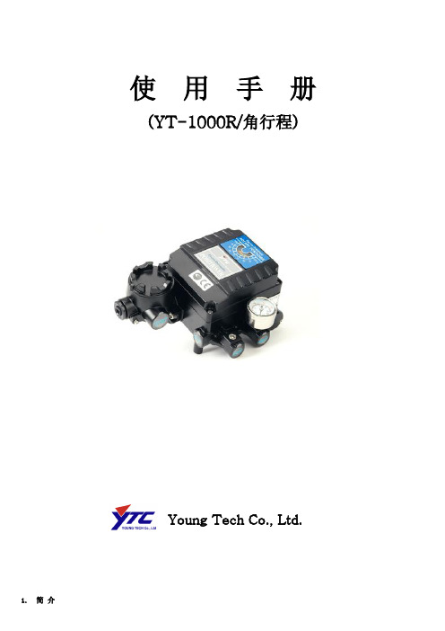
使用手册(YT-1000R/角行程)Young Tech Co., Ltd.1. 简介电-气阀门定位器YT-1000R是一种从控制器或控制系统中接受4~20mA电流信号,并向气动执行机构输送空气来控制阀门开度的装置。
2. 特征- 在5~200Hz范围内无共振现象。
- 不用更换零件只需简单操作即可进行1/2范围内的分程控制。
- 零调节和量程调节非常简单。
- 正作用和反作用,单作用和双作用之间可方便转换。
- 反馈杆连接非常简单。
- 反应速度快而准确。
- 空气消耗量小,经济性好。
- 在小型执行器也可利用先导阀的节流孔来防止振动现象。
3. 参数4. 订货编制:YT-1000R型号动作形式防爆等级反馈杆喷嘴连接形式环境温度选用配件1 选用配件2YT-1000R S单作用m ExdmIIBT5 1 M6×40L 1小于90㎤1 PT S -20℃~70℃0标准指示器0无D双作用c ExdmIICT5 2 M6×63L 2 90~180㎤2 NPT H -20℃~120℃1圆顶指示器1 +PTM(内置)I ExiaIIBT6 3 M8×40L 3大于180㎤L -40℃~70℃2 +PTM9(外置)n不防爆4 M8×63L 3 +L/S(内置)5 NAMUR 4 +L/S(外置)5 +PTM+L/S(内置) <备注>●以大气温度20℃,绝对压760㎜Hg,相对湿度65%为基准。
●本产品的基本配置适用于耐压封闭防爆(ExdmⅡBT6)及容器保护等级IP66。
●以单作用(Single Acting)为标准。
●用量程调节旋扭可达到1/2范围内的分程控制。
●标准类型以外的产品请另询问。
5. 结构图6. 动作原理为了改变阀门的位置增加输入电流。
由①力矩马达发生力,使②挡板和③喷嘴之间距离增加从而喷嘴背压急剧减小。
⑤阀芯向上移动,同时⑦气门被打开,把出口1导管空压送到⑩执行机构。
安全阀说明书
上海阀门厂有限公司安全阀使用说明书
四、安全阀的常温泵试及注意事项 !!友情提示:
为了保护安全阀的阀座、阀瓣密封面不受损,在转动安 全阀调整螺杆时应采取防止阀杆转动的措施。
1.安全阀的常温泵试应严格按照 GB12243《弹簧直接载荷式安 全阀》出厂前的试验的有关规定进行(除非订货合同中另为要求)。 常温泵试工作宜在空气试验台上进行。
2.安全阀应存放在干燥通风的室内,其进出口必须有防尘措施。 3.安装前必须仔细校对阀门上的标志和铭牌是否与使用要求符 合。 4.安全阀应直立安装,进口端平面应保持水平位置,并最好直 接安装在容器或管道的接头上。接头应尽可能地短,起内径应不小于 安全阀的公称通径。安全阀排放时介质流经接头的压降以不超过安全 阀允许的启闭压差的 50%为宜。 5.安全阀排放接管的内径应不小于出口通径,并尽可能地短, 尽可能地减少弯头,使排放介质流经的阻力尽可能地小。排放介质流 经排放接管的压降应小于 10%整定压力。 6.安装排放接管时应避免管道载荷或热应力附加到阀门上。 7.其它操作技术管理可按照国家有关部门颁布的有关安全规程 办理。
A48 型安全阀提升螺母装配不当使 横杆顶与提升螺母底呈有载荷接 触状态,致使阀瓣与阀座不能紧密 接触。
拆除横杆、保护罩、把提升螺母调整 到合理位置并牢固的固定再将保护 罩、横杆复位。(参见四之 7)
安全阀拒动作
安全阀工况下开启 压力偏高、阀门动 作时有频跳或颤振 现象
导向套与反冲盘(或阀瓣座)导向 面间、调整螺杆与阀杆导向面间有 杂务卡住。
4
上海阀门厂有限公司安全阀使用说明书
三、安全阀的运输、存放和安装 !!友情提示:
为了使安全阀无故障运行,在安全阀安装前必须确保阀 门内腔及进出口的清洁,同时要确保与安全阀相联接的容器 或管道内部的彻底清洁和冲管工作。
A03 - 5000-2NEW阀门说明书
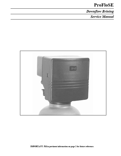
ProFloSEDownflow BriningService ManualIMPORTANT: Fill in pertinent information on page 2 for future reference.ProFloSE DownflowJob Specification SheetJob Number ___________________________________Model Number ________________________________Water Test ____________________________________Capacity Of Unit ________________________ Max. _____________ Per RegenerationMineral Tank Size: Diameter ___________________ Height _____________________Under Bedding ____________________________ Amount _______________________Type Of Media ____________________________ Cubic Feet _____________________Brine Tank Size ________________________________Salt Setting Per Regeneration ________________________________Valve ProgrammingTreated Water Capacity ______________________________ (Gallons / Liters)Regeneration Day Override _______________________________ (Max. Days Between Regen.) Regeneration Time ________________________________ ( A.M. ) ( P.M. )Notes:________________________________________________________________________________ ________________________________________________________________________________ ________________________________________________________________________________ ________________________________________________________________________________ ________________________________________________________________________________ ________________________________________________________________________________ ________________________________________________________________________________ Page 2Printed in U.S.A.Printed in U.S.A.Page 3ProFloSE DownflowGeneral Residential Installation Check ListWATER PRESSURE: A minimum of 20 psi inlet water pressure is required for regeneration valve to operate effectivelyELECTRICAL FACILITIES: An uninterrupted alternating current (A/C) supply is required. Please make sure your voltage supply is compatible with your unit before installation.EXISTING PLUMBING: Condition of existing plumbing should be free from lime and iron buildup. Piping that is built up heavily with lime and/or iron should be replaced. If piping is clogged with iron, a separate iron filter unit should be installed ahead of the water softener.LOCATION OF SOFTENER AND DRAIN: The softener should be located close to a clean working drain and connected according to local plumbing codes.BY-PASS V ALVES: Always provide for the installation of a by-pass valve if unit is not equipped with one.CAUTION: Water pressure is not to exceed 120 p.s.i., water temperature is not to exceed 110° F, and the unit cannot be subjected to freezing conditions.Valve Installation and Start-up ProceduresINSTALLATION INSTRUCTIONS1.Place the softener tank where you want to install the unit, making sure the tanks are level and on a firm base.2.All plumbing should be done in accordance with local plumbing codes. The pipe size for the drain line should be a minimum of 1/2″. Backwash flow rates in excess of 7 gpm or length in excess of 20´ require 3/4″ drain line.3.The 1″ distributor tube (1.050 O.D.) should be cut flush with top of tank.4.Lubricate the distributor o-ring seal and tank o-ring seal. Place the main control valve on tank. Note: Only use silicone lubricant.5.Solder joints near the drain must be done prior to connecting the Drain Line Flow Control fitting (DLFC). Leave at least 6″ between the DLFC and solder joints when soldering pipes that are connected on the DLFC. Failure to do this could causeinterior damage to the DLFC.6.Teflon tape is the only sealant to be used on the drain fitting.7.Make sure that the floor is clean beneath the salt storage tank and that it is level.8.On units with a by-pass, place in by-pass position. Turn on the main water supply. Open a cold soft water tap nearby and let run a few minutes or until the system is free from foreign material (usually solder) that may have resulted from the installation. Once clean, close the water tap.9.Place the by-pass in service position and let water flow into the mineral tank. When water flow stops, slowly open a cold water tap nearby and let run until the air is purged from the unit.10.Plug unit into an electrical outlet. Note: All electrical connections must be connected according to local codes.11.Add water to the top of the air check. Manually step the valve to the Brine Draw Position and allow the valve to draw water from the brine tank until it stops. Note: The air check will check at approximately the midpoint of the screened intake area.12.Next, manually step the valve to the Brine Refill Position and allow the valve to return to Service automatically.13.With the valve in Service, check that there is about 1.0″ of water above the grid in the brine tank, if used.14.Fill the brine tank with salt.15.Set-Up is now finished, the control can now be left to run automatically.Printed in U.S.A.Page 4ProFloSE DownflowControl Start-Up ProceduresWhenever the valve is in Service the current time of day can be set, the control programmed, or an extra regeneration initiated atany time.1. Set Time Of Day2. Enter Control Programming Mode1.Push and hold for 5 seconds both the Up and Down Set Buttons to enter Programming Mode. 2.Push the Extra Cycle Button once per display until all have been viewed and this mode is exited and normal operation is resumed.Printed in U.S.A.Page 5ProFloSE DownflowControl Start-Up Procedures (Cont’d.)Depending on current control programming, option setting displays that are not required to be set will not be viewed.3. Set Control Programming1.The first option setting display that appears in the Program Mode is Treated Water Capacity. Using the Set Up or Down Buttons, set the amount of treated water that can flow through the unit before a regeneration is required. For Example:3.Push the Extra Cycle Button. The third option setting display that appears is Regeneration Time. Using the Set Up or Down Buttons, set the maximum number of days b3efore a regeneration cycle must occur. For Example:2.Push the Extra Cycle Button. The second option setting display that appears is Regeneration Time. Using the Set Up or Down Buttons, set the desired time of day when a regeneration can occur, if required. For Example:4.Control programming is now complete. Push the Extra Cycle Button. This will exit the control from the Programming Mode, and resume Normal Operation.Printed in U.S.A.Page 6ProFloSE DownflowControl Start-Up Procedures (Cont’d.)4. Start An Immediate Extra CycleWhen starting an Extra Cycle, you will have one or two options:1.Press and Release the Extra Cycle Button:-With Immediate Regeneration controls the control will go into regeneration cycle immediately.-With Delayed Regeneration controls the Service Arrow will begin to flash immediately and a regeneration will occur at the present regeneration time (i.e. 2:00 a.m.)2.Press and Hold for 5 seconds the Extra Cycle Button:-With Delayed Regeneration controls, the control will go into regeneration cycle immediately.The following series of displays appear when the control enters a regeneration cycle:5. Regeneration Cycle DisplaysPrinted in U.S.A.Page 7ProFloSE DownflowControl Start-Up Procedures (Cont’d.)6. Fast Cycle Valve Thru Regeneration A.Once the valve reaches Regen Step #1 let water run to drain for about 5 minutes.Next, manually step the valve through a regeneration cycle checking valve operation in each step:B.Push the Extra Cycle Button once to advance the valve to Regen Step #2.C.Push the Extra Cycle Button once to advance the valve to Regen Step #3. (Optional)D.Push the Extra Cycle Button once to advance the valve to Regen Step #4. (Optional)E.Push the Extra Cycle Button once more to advance the valve back to Service.7. Final Set-UpWith proper valve operation verified:A.Add water to the top of the air check. Manually step the valve to the Brine Draw Position and allow the valve to draw water from the brine tank until it stops. Note: The air check will check at approximately the midpoint of the screened intake area.B.Next, manually step the valve to the Brine Refill Position and allow the valve to return to Service automatically.C.With the valve in Service, check that there is about 1.0″ of water above the grid in the brine tank, if used.D.Fill the brine tank with salt.E.Set-Up is now finished, the control can now be left to run automatically.Extra Cycle ButtonPrinted in U.S.A.Page 8ProFloSE DownflowControl OperationTimeclock Regeneration ValvesIn normal operation the Time Of Day Display will be viewed at all times. The control will operate normally until the number of days since the last regeneration reaches the Regeneration Day Override setting. Once this occurs, a regeneration cycle will then be initiated at the preset Regeneration Time.Flow Meter Equipped ValvesIn normal operation the Time Of Day Display will alternate being viewed with a V olume Remaining Display. This display will be in gallons. As treated water is used, the V olume Remaining Display will count down from a maximum value to zero or (----). Once this occurs a regeneration cycle will then be initiated immediately or delayed to the set Regeneration Time. Water flow through the valve is indicated by the Flow Dot that will flash in a direct relationship to flow rate. For Example:Immediate Regeneration Valves With Days Between Regeneration Override SetWhen the valve reaches its set Days Since Regeneration Override value a regeneration cycle will be initiated immediately. This event occurs regardless of the V olume Remaining display having reached zero gallons.Delayed Regeneration Valves With Days Between Regeneration Override SetWhen the valve reaches its set Days Since Regeneration Override value a regeneration cycle will be initiated at the preset Regeneration Time. This event occurs regardless of the V olume Remaining display having reached zero gallons.Control Operation During RegenerationIn Regeneration the control will display a special Regeneration Display. In this display the control will show the current regeneration step number the valve is advancing to, or has reached, and the time remaining in that step. The step number displayed will flash until the valve has completed driving to this regeneration step position. Once all regeneration steps have been completed the valve will return to Service and resume normal operation. For Example:Pushing the Extra Cycle Button during a regeneration cycle will immediately advance the valve to the next cycle step position and resume normal step timing.Control Operation During ProgrammingThe control will only enter the Program Mode with the valve in Service. While in the Program Mode the control will continue to operate normally monitoring water usage and keeping all displays up to date. Control programming is stored in memory permanently, without the need for battery backup power.Control Operation During A Power FailureDuring a power failure all control displays and programming will be stored for use upon power re-application. The control will retain these values for years, if necessary, without loss. The control will be fully inoperative and any calls for regeneration will be delayed. The control will upon power re-application resume normal operation from the point were it was interrupted. An indication that a power outage has occurred will be an inaccurate time of day display.Printed in U.S.A.Page 9ProFloSE DownflowMaster Programming Mode Entering Master Programming ModeWith the Time of Day Display set to 12:01 P.M., push and hold for 5 seconds both the Set Up and Set Down Buttons. The Program Indicator will turn on to signal that this mode is entered. In this mode all possible option settings may be viewed./Metric Display Format (U)This display is used to set the desired display format. This option setting is identified by the letter (U) in the first digit. There are three possible settings:Example:[ U - - 1 ] for US gallonsMetric format uses liters or cubic meters with a 24-hour timekeeping format. Regeneration timing in tenths of minutes.Example:[ U - - 2 ] for liters[ U - - 4 ] for cubic meters The SET UP or DOWN buttons will adjust this value.Depress the Extra Cycle Button to proceed to the next step.2.Regeneration Type (7)Depress the Extra Cycle Button. This display is used to set the Regeneration Type. This option setting is identified by the number 7 in the first digit. There are 3 possible settings:Timeclock Delayed. The control will determine that regeneration is required when the set Regeneration Time has been reached. The Regeneration Day Override setting will determine which days a regeneration cycle will be initiated.Example:[ 7 - - 1 ]Meter Immediate. The control will determine that regeneration is required when the available volume of softened water drops to or below zero. Regeneration to begin immediately.Example:[ 7 - - 2 ]Meter Delayed. The control will determine that a regeneration is required when the available volume of softened water drops to or below zero. Regeneration is to begin immediately at the set Regeneration Time.Example:[ 7 - - 3 ]The Set UP and DOWN Buttons will adjust this value.ProFloSE DownflowMaster Programming Mode (Cont’d.)3.Treated Water Capacity (No Display Code)Depress the Extra Cycle Button. This display is used to set the amount of treated water (gallons/liters) that can be produced by the unit before a regeneration cycle is required. With Meter Delayed Regeneration Type set, it will be up to the programmer to determine a reserve capacity and subtract that value from the calculated full capacity of the unit. This display will not be viewed with Timeclock Regeneration Type set.Example:Regenerates every 700 gallons or liters - [ 7 0 0 ]The Set UP and DOWN Buttons will adjust this value.4.Regeneration Time (No display Code)Depress the Extra Cycle Button. The next display viewed is the option setting for Regeneration Time. It is identified by a non-flashing colon between two sets of numbers. Set the desired time of day that a regeneration may occur, if required. This display will not be viewed with Meter Immediate Regeneration Type set.Example: 2 o’clock A.M. regeneration time - [ 2 : 0 0 ] (A.M. Indicator Dot On)The Set UP and DOWN Buttons will adjust this value.5.Regeneration Day Override (A)Depress the Extra Cycle Button. This display is used to set the maximum amount of time (in days) the unit can be in service without a regeneration. This option setting is identified by the letter ‘A’ in the first digit. With Meter Immediate Regeneration Type selected, regeneration will begin at the same point in time some amount of days ago when the last regeneration cycle was initiated. With Timeclock or Meter Delayed Regeneration Types selected, regeneration begins at the set Regeneration Time.An OFF setting will cancel this feature with all regeneration types except Timeclock Regeneration were it must be used.Example:Override every 7 days-[ A - - 7 ]Cancel setting -[ A O F F ] (Meter Immediate or Delayed Regeneration Types Only) The Set UP and DOWN Buttons will adjust this value.6.Regeneration Cycle Step Programming (1) (2) (3) (4) (5) (6)Depress the Extra Cycle Button. The next 2-4 displays viewed are part of a series of option settings used to program the Regeneration Cycle. Up to 4 steps can be programmed. Each display is used to set the duration time in minutes (or tenths of minutes - Metric) of that specific step in a regeneration cycle. A step # will turn on for the regeneration cycle step being programmed. Regeneration steps are skipped by setting the display to 0 and regeneration ended by setting the step # after the last active step to OFF, as shown below and on the next page:Examples:Regeneration Cycle Step #1 - 8 minutes-[ 1 - - 8 ]Regeneration Cycle Step #3 - skipped-[ 3 - - 0 ]Example:lbs. salt ÷ 3 ÷ B.L.F.C. Size = refill time in minutes, 10 lbs. salt ÷ 3 ÷ .25 = 13.3 minute refillThe Set UP and DOWN Buttons will adjust these values.Page 10Printed in U.S.A.ProFloSE DownflowMaster Programming Mode (Cont’d.)7.Flow Meter Size (F)Depress the Extra Cycle Button. The next display is used to set the flowmeter size. This option setting is identified by the letterF in the first digit. In this display set the proper amount of pulses generated by the flow meter for each gallon or liter of waterflow. This setting will not be viewed with Timeclock Regeneration Type selected.Examples:[ F 1 3 1 ] 3/4″ Turbine Flow Meter (US Format)[ F 3 4.6 ] 3/4″ Turbine Flow Meter (Metric Format)The Set UP and DOWN Buttons will adjust this value.8.Valve Type (o)Depress the Extra Cycle Button. This display is used to set the type of valve used with the control. This option setting is identified by the letter o in the first digit. There are two possible selections with #1 being the required setting.Examples:[ o - - 1 ] ProFloSE Valve Operation[ o - - 2 ] Option Not Typically UsedThe Set UP and DOWN Buttons will adjust this value.9.Line Frequency (LF)Depress the Extra Cycle Button. This display is used to set the frequency of the power applied to the control. When properly set, all timekeeping functions will remain accurate. This option setting is identified by the letters LF in the first digit. There are two possible selections.Examples:[ L F 5 0 ] 50Hz Line Frequency Operation[ L F 6 0 ] 60Hz Line Frequency OperationThe Set UP and DOWN Buttons will adjust this value.Exiting This Option Setting LevelPush the Extra Cycle Button once per display until all have been viewed. The Program Mode will be exited and normal operation resumed.Resetting Permanent Programming Memory -Push and hold the Set Up and Down Buttons for 25 seconds or until the Time Of Day Display resets to 12:00 P.M. All option setting will then reset to the default values. Control programming will then have to be reset as necessary.ProFloSE DownflowMaster Programming Mode Flow ChartNote:1.Set Time Of Day Display To 12:01 P.M.2.Push And Hold The Set Up And SetDown Button For 5 Seconds.3.Push Extra Cycle Button Once PerDisplay Until All Displays Are ViewedAnd Normal Operation Is Resumed.4.Option Setting Displays May BeChanged As Required By PushingEither The Set Up Or Down Button.5.Depending On Current ValveProgramming Certain Displays WillNot Be Able To Be Viewed Or Set.ProFloSE Downflow Dimensional DrawingProFloSE DownflowWater Conditioner Flow Diagrams1 SERVICE POSITIONHard water enters unit at valve inlet and flows around the piston down thru the mineral in the mineral tank.Conditioned water enters center tube thru the bottom distributor then flows up thru the center tube and tothe outlet of the valve.2 BACKWASH POSITIONHard water enters unit at valve inlet - flows around piston - down center tube - thru bottom distributorand up thru the mineral - around the piston and out the drain line.ProFloSE Downflow Water Conditioner Flow Diagrams (Cont’d.)Brine. Hard water enters unit at the valve inlet - flows into injector housingand thru nozzle and throat to draw brine from the brine tank - brine flowsdown thru mineral and enters the center tube thru bottom distributor and outthru the drain line.Slow Rinse. Hard water enters unit at valve inlet - flows into injector housing and thru nozzle and throat down thru mineral and enters the center tube thru bottom distributor and out thru the drain line.3BRINE/SLOW RINSE POSITIONHard water flows from inlet around the piston down thru the mineral intobottom distributor and up thru center tube - thru piston and out thru the drainline.Hard water enters unit at valve inlet and flows around the piston down thru the mineral. Conditioned water flows up thru the center tube - flows thru the injector housing - thru the brine valve to fill the brine tank.4 RAPID RINSE POSITION5 BRINE TANK FILL POSITIONProFloSE Downflow Valve Powerhead Assembly (See opposite page for parts list)ProFloSE DownflowValve Powerhead AssemblyParts ListItem No.Quantity Part No.Description1. . . . . . . . . . . . 1 . . . . . . . . . . . . .40269. . . . . . . . . . . . . . . . . . Plate, Front2. . . . . . . . . . . . 1 . . . . . . . . . . . . .40326. . . . . . . . . . . . . . . . . . Label, Cover-up3. . . . . . . . . . . . 1 . . . . . . . . . . . . .19474. . . . . . . . . . . . . . . . . . Harness, Power4. . . . . . . . . . . . 1 . . . . . . . . . . . . .40283. . . . . . . . . . . . . . . . . . Circuit Board, SE Timer5. . . . . . . . . . . . 1 . . . . . . . . . . . . .40376. . . . . . . . . . . . . . . . . . Button, Conductive6. . . . . . . . . . . . 1 . . . . . . . . . . . . .19471-02 . . . . . . . . . . . . . . . Cover, Front Panel7. . . . . . . . . . . . 1 . . . . . . . . . . . . .19697-01 . . . . . . . . . . . . . . . Label, Display8. . . . . . . . . . . . 1 . . . . . . . . . . . . .19791-01 . . . . . . . . . . . . . . . Meter Cable Assy., Turbine9. . . . . . . . . . . . 2 . . . . . . . . . . . . .10218. . . . . . . . . . . . . . . . . . Switch, Micro10 . . . . . . . . . . . 2 . . . . . . . . . . . . .17876. . . . . . . . . . . . . . . . . . Screw #4-40 x 1.12511. . . . . . . . . . . . 1 . . . . . . . . . . . . .19927. . . . . . . . . . . . . . . . . . Cam, Switch Downflow12 . . . . . . . . . . . 1 . . . . . . . . . . . . .18211-01 . . . . . . . . . . . . . . . Gear, Main Downflow13 . . . . . . . . . . . 1 . . . . . . . . . . . . .18228. . . . . . . . . . . . . . . . . . Cam, Brine, Downflow14 . . . . . . . . . . . 1 . . . . . . . . . . . . .18202-03 . . . . . . . . . . . . . . . Back Plate15 . . . . . . . . . . . 1 . . . . . . . . . . . . .40251. . . . . . . . . . . . . . . . . . Motor Assy., 24V 50/60Hz16 . . . . . . . . . . . 2 . . . . . . . . . . . . .13602. . . . . . . . . . . . . . . . . . Screw, Rd. Hd. 6-33 x 5/1617 . . . . . . . . . . . 1 . . . . . . . . . . . . .19674. . . . . . . . . . . . . . . . . . Transformer U.S. 24V (120V) 50/60Hz1 . . . . . . . . . . . . .25651. . . . . . . . . . . . . . . . . . Transformer European 24V (230V)18 . . . . . . . . . . . 1 . . . . . . . . . . . . .13547. . . . . . . . . . . . . . . . . . Strain Relief19 . . . . . . . . . . . 4 . . . . . . . . . . . . .12681. . . . . . . . . . . . . . . . . . Nut, Wire, Beige20 . . . . . . . . . . . 1 . . . . . . . . . . . . .13363. . . . . . . . . . . . . . . . . . Washer, Plain, .145 I.D.21 . . . . . . . . . . . 1 . . . . . . . . . . . . .18259-02 . . . . . . . . . . . . . . . Cover, Back Black22 . . . . . . . . . . . 6 . . . . . . . . . . . . .13296. . . . . . . . . . . . . . . . . . Screw, Hex Washer 6-20 x 1/223 . . . . . . . . . . . 1 . . . . . . . . . . . . .18260-00 . . . . . . . . . . . . . . . Cover, Front Smoke24 . . . . . . . . . . . 2 . . . . . . . . . . . . .18261. . . . . . . . . . . . . . . . . . Screw, Hex Head, 10-24 x 13/16Not Shown . . . . 1 . . . . . . . . . . . . .14044. . . . . . . . . . . . . . . . . . Cable TieProFloSE Downflow Control Valve Assembly (See opposite page for parts list)ProFloSE DownflowControl Valve AssemblyParts ListItem No.Quantity Part No.Description1. . . . . . . . . . . . . . 1 . . . . . . . . . . . . . 18815 . . . . . . . . . . . . . Valve Body, 5000, 1″ Dist.2. . . . . . . . . . . . . . 1 . . . . . . . . . . . . . 18264 . . . . . . . . . . . . . Spacer, End3. . . . . . . . . . . . . . 4 . . . . . . . . . . . . . 14241 . . . . . . . . . . . . . Spacer4. . . . . . . . . . . . . . 5 . . . . . . . . . . . . . 13242 . . . . . . . . . . . . . Seal5. . . . . . . . . . . . . . 1 . . . . . . . . . . . . . 18265 . . . . . . . . . . . . . Piston, Downflow6. . . . . . . . . . . . . . 1 . . . . . . . . . . . . . 14309 . . . . . . . . . . . . . Retainer, Piston Rod7. . . . . . . . . . . . . . 1 . . . . . . . . . . . . . 18268 . . . . . . . . . . . . . End Plug Assembly8. . . . . . . . . . . . . . 3 . . . . . . . . . . . . . 18261 . . . . . . . . . . . . . Screw, Hex Washer Head, 10-24 x 13/169. . . . . . . . . . . . . . 1 . . . . . . . . . . . . . 18267 . . . . . . . . . . . . . Piston Rod10. . . . . . . . . . . . . 1 . . . . . . . . . . . . . 17978 . . . . . . . . . . . . . Brine Valve Stem11. . . . . . . . . . . . . 1 . . . . . . . . . . . . . 18755 . . . . . . . . . . . . . Seat, Brine Valve12. . . . . . . . . . . . . 1 . . . . . . . . . . . . . 13167 . . . . . . . . . . . . . Spacer, Brine Valve13. . . . . . . . . . . . . 1 . . . . . . . . . . . . . 12550 . . . . . . . . . . . . . Quad Ring, -00914. . . . . . . . . . . . . 2 . . . . . . . . . . . . . 13302 . . . . . . . . . . . . . O Ring, -01415. . . . . . . . . . . . . 1 . . . . . . . . . . . . . 13165 . . . . . . . . . . . . . Cap, Brine Valve16. . . . . . . . . . . . . 1 . . . . . . . . . . . . . 11973 . . . . . . . . . . . . . Spring, Brine Valve17. . . . . . . . . . . . . 1 . . . . . . . . . . . . . 16098 . . . . . . . . . . . . . Washer, Plain, Nylon18. . . . . . . . . . . . . 1 . . . . . . . . . . . . . 11981-01. . . . . . . . . . . Retaining Ring19. . . . . . . . . . . . . 1 . . . . . . . . . . . . . 11183 . . . . . . . . . . . . . O-Ring, -01720. . . . . . . . . . . . . 1 . . . . . . . . . . . . . . . . . . . . . . . . . . . . . . . . Flow Washer (specify size)21. . . . . . . . . . . . . 1 . . . . . . . . . . . . . 11385-01. . . . . . . . . . . Flow Control Housing, Plastic22. . . . . . . . . . . . . 1 . . . . . . . . . . . . . 18312 . . . . . . . . . . . . . Retainer, Drain23. . . . . . . . . . . . . 1 . . . . . . . . . . . . . 13304 . . . . . . . . . . . . . O-Ring, -12124. . . . . . . . . . . . . 1 . . . . . . . . . . . . . 18303 . . . . . . . . . . . . . O-Ring, -33625. . . . . . . . . . . . . 2 . . . . . . . . . . . . . 10141 . . . . . . . . . . . . . O-Ring, -01026. . . . . . . . . . . . . 1 . . . . . . . . . . . . . 18276 . . . . . . . . . . . . . Plug, Injector27. . . . . . . . . . . . . 2 . . . . . . . . . . . . . 13771 . . . . . . . . . . . . . O-Ring, -01228. . . . . . . . . . . . . 1 . . . . . . . . . . . . . 18275-X . . . . . . . . . . . Injector Throat (specify size) 000, 00, 0, 1, 2, 329. . . . . . . . . . . . . 1 . . . . . . . . . . . . . 18274-X . . . . . . . . . . . Injector Nozzle (specify size) 000, 00, 0, 1, 2, 330. . . . . . . . . . . . . 1 . . . . . . . . . . . . . 18273 . . . . . . . . . . . . . V ortex Generator31. . . . . . . . . . . . . 1 . . . . . . . . . . . . . 18271 . . . . . . . . . . . . . Screen Injector32. . . . . . . . . . . . . 1 . . . . . . . . . . . . . 18301 . . . . . . . . . . . . . Seal, Injector33. . . . . . . . . . . . . 1 . . . . . . . . . . . . . 18277 . . . . . . . . . . . . . Cap, Injector, Softener34. . . . . . . . . . . . . 2 . . . . . . . . . . . . . 18262 . . . . . . . . . . . . . Screw, Hex Washer Head, 10-24 x 135. . . . . . . . . . . . . 1 . . . . . . . . . . . . . 12977 . . . . . . . . . . . . . O-Ring, -01536. . . . . . . . . . . . . 1 . . . . . . . . . . . . . 13245 . . . . . . . . . . . . . Retainer, BLFC Button37. . . . . . . . . . . . . 1 . . . . . . . . . . . . . . . . . . . . . . . . . . . . . . . . Flow Washer (specify size)38. . . . . . . . . . . . . 1 . . . . . . . . . . . . . 13244 . . . . . . . . . . . . . Adapter, BLFC39. . . . . . . . . . . . . 1 . . . . . . . . . . . . . 13308 . . . . . . . . . . . . . Hose Barb, Black, 1/2 x 1/2 Straight1 . . . . . . . . . . . . . 12338 . . . . . . . . . . . . . Hose Barb, Black, 1/2 x 1/2 90° Elbow40. . . . . . . . . . . . . 1 . . . . . . . . . . . . . 18280 . . . . . . . . . . . . . Top Collector, 1″, X .011, Gray1 . . . . . . . . . . . . . 18280-01. . . . . . . . . . . Top Collector, 1″, X .020 White, Wide Slot1 . . . . . . . . . . . . . . 18280-02. . . . . . . . . . . .Top Collector, 1″, X .008 Red, Narrow Slot41 . . . . . . . . . . . . . 1 . . . . . . . . . . . . . . 14613 . . . . . . . . . . . . . .Flow StraightenerOPTIONAdapter Coupling Day Clock Only45. . . . . . . . . . . . . 2 . . . . . . . . . . . . . 19228 . . . . . . . . . . . . . Adapter Coupling46. . . . . . . . . . . . . 4 . . . . . . . . . . . . . 13305 . . . . . . . . . . . . . O-Ring, -11947. . . . . . . . . . . . . 2 . . . . . . . . . . . . . 13255 . . . . . . . . . . . . . Clip, Mounting48. . . . . . . . . . . . . 2 . . . . . . . . . . . . . 13314 . . . . . . . . . . . . . Screw, Hex Washer Head 8-18 x 5/8。
Eaton Hydraulics DG17S4-100A C N 方向控制阀门操作手册说明书
Vickers®
Directional Controls
Manual Lever Operated Directional Valve
DG17S4-10*A-53 DG17S4-10*C-53 DG17S4-10*N-53
Revised 09-01-85
I-3564-S
Model
:J407533 Plug Y263493 ‘‘O’’ Ring
416834 Rivet (4 req’d) ID Plate (See table) Rod (See table) Y263493 ‘‘O’’ Ring :J407533 Plug
:J407533 Plug Y263493 ‘‘O’’ Ring
Model Code
1
2
3 45
6
1 Seals
3 Valve Size
F3 - Multi-fluid capability (VitonR seals) 100 series - 1.250 inch (31,7 mm)
Viton is a registered trademark of E.I. DuPont
Offset (A)
Spring No-Spring
LH RH Center (C) Detent (N)
434310 431539 434310 431539 434310 431539
431900 431540 431549 431902 431549 431902
431903 431541 431905 431906 431905 431906
286791 Knob 288720 Lever
287718 Clevis (Assemble with flat in position shown.)
安全阀调整操作规程示范文本
安全阀调整操作规程示范文本In The Actual Work Production Management, In Order To Ensure The Smooth Progress Of The Process, And Consider The Relationship Between Each Link, The Specific Requirements Of EachLink To Achieve Risk Control And Planning某某管理中心XX年XX月安全阀调整操作规程示范文本使用指引:此操作规程资料应用在实际工作生产管理中为了保障过程顺利推进,同时考虑各个环节之间的关系,每个环节实现的具体要求而进行的风险控制与规划,并将危害降低到最小,文档经过下载可进行自定义修改,请根据实际需求进行调整与使用。
(1)开启压力的调整①安全阀出厂前,应逐台调整其开启压力到用户要求的整定值。
若用户提出弹簧工作压力级,则一般应按压力级的下限值调整出厂。
②使用者在将安全阀安装到被保护设备上之前或者在安装之前,必须在安装现场重新进行调整,以确保安全阀的整定压力值符合要求。
③在铭牌注明的弹簧工作压力级范围内,通过旋转调整螺杆改变弹簧压缩量,即可对开启压力进行调节。
④在旋转调整螺杆之前,应使阀进口压力降低到开启压力的90%以下,以防止旋转调整螺杆时阀瓣被带动旋转,以致损伤密封面。
⑤为保证开启压力值准确,应使调整时的介质条件,如介质种类、温度等尽可能接近实际运行条件。
介质种类改变,特别是当介质聚积态不同时(例如从液相变为气相),开启压力常有所变化。
工作温度升高时,开启压力一般有所降低。
故在常温下调整而用于高温时,常温下的整定压力值应略高于要求的开启压力值。
高到什么程度与阀门结构和材质选用都有关系,应以制造厂的说明为根据。
⑥常规安全阀用于固定附加背压的场合,当在检验后调整开启压力时(此时背压为大气压),其整定值应为要求的开启压力值减去附加背压值。
阀门管理说明书
阀门管理说明书阀门管理(单阀顺序阀)这是一个与阀门管理程序有关的派生方式。
它可以在“司机自动”或“汽轮机手动”方式下被选用,但是如果在“汽轮机手动”时被选用,则在接着采用“司机自动”之前,不能先作阀门方式的切换。
大司机操作盘上,装有一个带分透镜的“单阀—顺序阀”按扭,其功能是使运行人员对汽轮发电机组的调节阀即可选择单阀控制方式,也可选择顺序控制方式。
实际上这是一个程序,使运行人员即可以选择顺序阀控制,又可以选择单阀控制。
控制方式的选择是根据汽轮机第一级后的蒸汽温度,因为这个温度是随着控制方式而变化的。
在机组运行期间,运行人员在任何时候都可以改变阀门方式。
但是运行人员应当注意,在控制方式切换的瞬间,会产生一个瞬时的温度变化。
在低负荷下,用单阀方式时的第一级温度比用顺序阀方式时大约高42℃~56℃。
这个温差逐渐减小,直到“阀全开”工况时温差消失。
合理选择和使用阀门控制方式,运行人员能够在各运行阶段尽量减小第一级的温度变化,这样,使高压转子和其它零件的热应力减小。
下述内容适用于运行的各个阶段。
1升速和带最低负荷一般来说,在升速、同步和带低负荷时应采用单阀方式。
在这种方式下,蒸汽通过所有调节阀和喷嘴室,在3600全周进入调节级动叶片。
这样,这些零件的加热和膨胀比较均匀,当采用顺序阀控制方式时,也有可能出现根据当时主蒸汽的参数,使第一级的蒸汽温差同金属温度有一个较好地匹配。
并允许较快速启动,运行人员可以参考“热态启动推荐值—升速和带最低负荷”图表来决定。
在机组试运转的最初阶段,必须使用单阀运行方式,在这期间,整个电厂的各种控制装置和控制系统未能全部正常投运之前,非正常的压力和温度的波动是经常发生的。
为了保证汽轮发电机组的安全可靠,要尽量减小这种不正常工总值对机组的影响。
在部分负荷下,调节级全周进汽的载荷小于在部分进汽时的载荷。
同时在全周进汽时叶片的温度也比较高,这对于叶根和轮缘部位的机械载荷的均匀分布是有利的因此,在最初6个月的运行期间里,汽轮机应采用全周进汽,即单阀运行方式。
DATIAN 500X 泄压 持压阀 说明书
500X泄压/持压阀 使用说明书 一、产品介绍该阀是本单位工程技术人员参照美国、法国和国内同类型的先进产品进行研制而成的一种新型阀门。
在传动方式上采用了水力操作并能自动控制,即利用控制管路中的压差自动开合,关闭主阀,使上游的压力不超过某一设定值。
阀体采用了全通道流线型设计,流体阻力小密封性能好,自动启闭性能灵敏。
该阀的主要特点是既可以作泄压阀,又可以作持压阀。
作泄压阀时可将给水管路中超过向导阀安全设定值之压力释放掉,并维持管路中压力于—安全设定值以下,以防止管路中高压或突压毁损管线或设备,可用于高层大楼消防测试循环系统以及其它给水平系统之泄压用,防止水压过高造成系统危险;作持压阀时可维持主阀上游供水压力于某一设定值以上,以保障主阀上游供水区的压力。
主要用于城市低压供水区域。
总之该产品是用于供水系统的理想产品,欢迎选购。
二、结构形式活塞型结构图该阀由主阀、导阀、针阀、球阀、压力表等组成,按不同管径分有隔膜式和活塞式。
由于导阀、针阀.、球阀和压力表等要用导管与主阀连接,所以统称为导管控制系统。
三、主要零件与材料隔膜型结构图编号 零件名称 材 质 编号 零件名称 材 质1 阀 体 铸铁、铸钢、不锈钢10 压缩弹簧 不锈钢2 阀 座 铜、不锈钢 11 阀 杆 不锈钢3 密封垫 强化橡胶 12 球 阀 铜4 密封垫压板 铜、不锈钢 13 导 阀 铜5 阀 盘 铜、不锈钢 14 球 阀 铜6 膜 片 强化橡胶 15 压力表7 膜片压板 铜、不锈钢 16 球 阀 铜8 阀 盖 铸铁、铸钢、不锈钢17 针 阀 铜9 球 阀 青 铜 18 微型过滤器 不锈钢四、工作原理与用途作泄压阀时,主阀安装于泄水旁路,即与主管道并联安装。
当上游压力逐渐上升超过导阀13设定值时,主阀迅速开启泄水降压,直到上游压力降到导阀13设定值以下时,主阀才缓慢平稳关闭,并避免了水锤水击的发生,保证了管线的安全。
作泄压阀时,主要用于消除因流量供大于需而逐渐增大的过高压力,如消火栓系统的消防初期、自动喷淋以及各种给水系统的水泵出口处。
阀门说明书总汇
7.1.1概述简介:本系统用于控制和关断进入高压缸和中压缸的蒸汽流量。
本系统主要构成如下:——两个主汽阀(高压主汽阀)——四个调节阀(高压调节阀)及整体阀壳——两个中压联合汽阀(中压主汽阀和中压调节阀)中压联合汽阀的主汽阀和调节阀共用一个阀壳和阀座。
高压调节阀阀壳:蒸汽从过热器流出后经高压调节阀阀壳进入汽轮机。
高压调节阀阀壳通过短管联接于主汽阀壳下游。
高压调节阀阀壳通过四个弯曲并有一定柔性的高压主汽管与汽缸相接,保证汽轮机可以自由膨胀并不会在汽缸高压进汽法兰处产生不合适的应力。
为防止固体异物被蒸汽带入汽轮机对叶片造成损害,蒸汽要通过一个环绕主汽阀的网眼直径为4.Omm的圆柱滤网。
新机应特别注意防止蒸汽从管道中带出的焊渣、渣滓等对叶片造成的危害。
因此,在汽轮机第一次试运行时,需要装一个大约14目的精细滤网。
即便很小的颗粒也能对叶片造成严重损害,因此在机组试运行前对所有管系进行吹管就显得非常必要。
中压联合汽阀阀壳:再热蒸汽从再热器流出后经中压联合汽阀阀壳进入中压缸。
中压联合汽阀阀壳内有中压联合汽阀(中压主汽阀和中压调节阀)和滤网。
两个不同功用的阀,即再热主汽阀和再热调节阀共用一个阀壳,可以尽可能地简化中压联合汽阀的结构。
中压联合汽阀通过弹簧支架支撑在基础预埋件上,并通过短管与汽缸连接。
这样,在甩负荷时中压调节阀后的管段内不至存太多蒸汽,从而降低了超速的趋势。
中压联合汽阀阀壳:主汽阀:蒸汽轮机有两个主汽阀,主要用于在汽机紧急时切断汽流和在机组启动时用于预暖调节阀腔室。
另外,主汽阀还对进入汽机的蒸汽流量进行有效的控制,中间再热蒸汽透平要求在再热回路上额外安装一个主汽阀。
这些阀门都需要一些必须的压力调节,以避免工作压力和工作温度过高。
降温可以降低压力,从而保护汽阀阀壳和阀门装置。
蒸气回路装置设计的时压降要最小,所以要单独使用一个控制阀。
为了避免工作中很高的蒸气压力,主汽阀要求被安装在产生最高压力的部位,为了减少阀门开合时的耗能,有些阀门自身还拥有更小的阀门,而这些小阀门的开合取决于主汽阀。