MC700系列说明书
MC700系列说明书

MC700系列智能多媒体控制系统Intelligent Multimedia Control System(适用于MC700系列机型)用户手册User’s Manual**请在安装使用前认真阅读本说明书**尊敬的用户:感谢您选购我们生产的700系列多媒体中央控制器。
该产品具有外观设计小巧高档大方;使用简单方便;功能强大;扩展能力极强;可直接外接其他厂家的设备,三个可编程232口最多可同时控制三个不同厂家的投影机或两个不同厂家矩阵;可对各接口重新定义和单独控制;投影机一键切换;投影幕自动升降;开机即是电脑画面等等多种实用功能。
为了您能安全地使用本设备,发挥其最大的功能,强烈建议在安装使用前先仔细阅读本说明书。
若有任何技术问题或对产品的意见和建议,请与本公司技术服务部联系。
联系方法如下:电话:(020) 33534881 61087188传真:(020)61087188-8002地址:广州市天河软件园建工路9号4楼南区A1邮编:510665EMAIL:laitong@http://特别提醒:1.在使用本系统的时候,严禁在开机时对各个部件进行插拔(特别是通讯口及VGA接口,这可能会人为损坏设备)。
2 本控制器为智能开关设计,在雷雨天气或长时间不使用时,关闭电源总闸。
3.本控制器内有强电模块,严禁带电自行维修。
4.因中控本身已做好接地处理,为有效保护中控及设备,请在强电输入部分做好接地措施!目录一、使用说明 (4)1中控简介 (4)2、中控组成 (4)二、硬件连接 (5)1.连线说明 (5)三、系统设置 (7)1、系统通讯协议 (7)2、开机状态设置 (10)3、开关机流程设置 (10)4、开关延时设置 (11)5、投影机设置 (12)6、红外学习 (13)7、按键面板设置 (14)8、其他设置 (17)四.常见故障处理 (18)1、通过控制面板“系统开”无法开机 (18)2、红外学习不成功或显示成功却不能遥控 (18)3、有些设备红外遥控不灵 (19)4、投影机打不开 (19)5、中控与电脑连接失败 (19)一、使用说明1中控简介智能多媒体控制系统为现代化的会议中心、电化教室及家居提供了最佳的解决方案。
PWC_MC700_主控模块_说明书_V01.33
mc700使用说明书31外型尺寸图31尺寸图32端子定义和接线图端子号标识24v模块工作正电源建议使用24v开关电源0v模块工作电源地pe模块保护地接大地in1数字量输入1接设备的干接点in2数字量输入2接设备的干接点in3数字量输入3接设备的干接点in4数字量输入4接设备的干接点com数字量输入公共端10保留11保留12保留13pe备用14can总线的终端电阻接口r和r之间接一个60120欧姆的电阻15can总线的终端电阻接口r和r之间接一个60120欧姆的电阻16canhcan总线接口接子模块的canh17canlcan总线接口接子模块的canl18shdcan总线屏蔽层接口接子模块的总线屏蔽层接口19保留20txd模块com1的发送端21rxd模块com1的接收端22gnd模块com1的信号地23保留mc700使用说明书24保留25txd模块com2的发送端26rxd模块com2的接收端27gnd模块com2的信号地28o1干接点输出129o1干接点输出130o2干接点输出231o2干接点输出232保留33保留34485接口a信号端子35485接口b信号端子36shd485接口屏蔽层接线端子图32接线图mc700使用说明书显示及按键说明图41面板图如图41所示为led段码显示区
700采煤机说明书

700电牵引采煤机使用说明书电气部分型号:MGTY300/请将此使用说明书交给最终用户手里太原矿山机器集团电气发展有限公司前言非常感谢使用MGTY300/电牵引采煤机。
本使用说明书,叙述了700采煤机电气系统的配置、运行、维护、保养及检查等项目。
使用前,谨请认真阅读本使用说明书。
同时,请您在熟读本产品安全注意事项的基础上使用。
目录第一部分电气系统简介1第二部分控制箱3第三部分高压箱6第四部分先导回路主电源分配9第五部分控制中心9第六部分遥控系统功能及原理13第七部分变频器15第八部分电气系统操作18第九部分参数显示器21第十部分维护30附录A 31700电牵引采煤机使用说明书电气部分(Ⅳ型电控系统)型号:MGTY300/700—请将此使用说明书交给最终用户的手中太原矿机电气发展有限公司第一部分电气系统简介1.机型:MGTY 300/700—MG—滚筒式采煤机TY—太原300—单向截割功率700—装机总功率—供电电压1140VD—电牵引2.机组的供电:单电缆供电供电电缆的型号:MCP 3×95+1×35+4×63.特点:多电机横向布置,抽屉式结构,安装维护方便。
机载式交流变频调速,一拖二牵引方式,可实现功率平衡。
关键的电气部件全部采用进口件,提高了系统的可靠性。
低功耗的遥控系统,免充电式无线发射,可离机操作,既增加了安全性,而且待机时间长。
带故障记录的中文人机界面,缩短了故障查询时间。
保护齐全,增加了系统的使用寿命。
4.电气系统的基本配置:表一:5.电气系统的保护在采煤机上完成截割电机的温度监测及热保护油泵电机的温度监测牵引变压器的热保护对截割电机和牵引电机恒功率控制过载保护电机的漏电闭锁控制完成对运输机的闭锁控制第二部分控制箱1.功能结构控制箱位于主机架中央,它可从采空侧方便地推入和抽出,主要功能是完成采煤机的控制和监测。
控制箱分为两个箱体一个接线腔和一个隔爆腔,隔爆腔和接线腔之间用接线柱和过线组来连接,接线柱连接主回路,过线组连接控制信号回路。
「0I-MC系列加工中心使用说明书」

X10移动量:0.01mm/P
X100移动量:0.1mm/P
选择手轮方式后,选择X1、X10、X100任一倍率,再选择希望移动的座标轴(操作面板上相应的轴选指示灯亮),旋动手摇轮,可将滑板移动到指定的位置。手摇轮顺时针旋动发出正向指令,逆时针旋动发出负向指令。
FANUC手持盒
[DNC]DNC运行方式(RMT)是自动运行方式的一种,是在读入接在阅读机/穿孔机接口的外设上程序的同时执行自动加工(DNC运行)。它可以选择存储在外部输入/输出设备上的文件(程序)。
济南白马永诚机械制造有限公司
使 用说明 书
第
3-5
页
共
3-12
页
3)手动方式
1)[手轮]用于使用手持盒上的手轮移动滑板,此时移动轴和移动倍率均由手持盒上的选择开关选择:
页
共
2-3
页
2电源
2-1输入电压
本机床输入电源电压为三相交流380V 50HZ(出国可选择三相交流415V50HZ/60HZ或220V60HZ)。
电压波动允许在+10%,-15%范围内,否则,机床不能正常工作。
2-2主电源导线规格
主电源开关:100A(VMC450LVMC500L);150A(VMC700/800)
准备操作机床
2-5-2电源的断开
1、压下操作面板上NC“断开”键
2、左旋转主电源开关
注:必须严格按上述机床电源通、断电顺序要求操作,否则,会造成对系统的损坏。
济南白马永诚机械制造有限公司
使用说 明书
第
3-1
页
共
3-12
页
3、操作面板介绍操作面板见下图:
下面对每一按钮与开关逐一介绍:
CMI700产品说明书
C M I700系列产品说明书1.产品介绍1.1 仪器用途1.2 工作环境1.3 供电联接2.安装2.1.1 拆箱2.1.2 连线2.1.3 主要联接2.1.4 打印机(可选配)2.1.5 探头3.仪器构造3.1 前面板3.2 后面板3.3 键盘3.4 菜单构成3.4.1 跳过3.4.2 语言3.4.3 对比度3.4.4 打印机开/关3.4.5 关于屏幕3.4.6 安装菜单3.4.7 EMX/MRX/BMX模块菜单4.启动4.1 系统安装4.2 调校4.3 测量4.4 输入屏5.安装菜单5.1 时间设定5.2 用户控制屏5.3 打印机选项屏5.4 模式系列选项屏5.5 系统选项屏5.6 工厂选项屏5.7 调校和调整屏5.8 测试和选项屏6.E M X模块菜单6.1 操作原理6.2 EMX调校6.2.1 调校程序6.2.2 EMX调校明细屏6.2.3 EMX编辑/变更调校屏6.2.4 EMX重新调校7.M R X模块菜单7.1 操作原理7.2 MRX调校7.3 调校程序7.4 MRX调校明细7.5 MRX编辑/变更调校7.6 MRX重新调校7.7 快检板应用8.B M X模块菜单8.1 操作原理8.2 BMX调校8.2.1 调校程序8.2.2 BMX调校明细8.2.3 BMX编辑/变更调校8.2.4 BMX重新调校9.测量9.1 测量模式9.2 测量程序9.3 测量屏9.3.1 测量屏---单读9.3.2测量屏---复读9.3.3测量屏---趋势图9.3.4测量屏---X&R图9.3.5 柱状图10.打印10.1 打印控制屏10.2 票单打印样品10.3 题头打印样品11.规格11.1.1 一般规格11.1.2 涡流模式11.1.3 磁性模式11.1.4 镀镍模式11.2 MRX 模块11.2.1 TRP微型探头11.2.2 TRP标准探头11.3 BMX模块11.3.1 PM-147同位素11.3.2 TL-204同位素11.3.3 SR-90同位素12. 维护12.1 清洁12.2 电池1. 产品介绍1.1仪器用途CMI700系列是一款具有标准组件,无破坏性的涂/镀层厚度测量仪,其设计目的为精确测量不同基材上的不同涂/镀层厚度,CMI700系列产品可与以下三款测量模块联合配置:MRX,BMX,EMX.EMX 模块可与任一磁性,涡流或镀镍测量原理配置.1.2工作环境该仪器采用测量粗糙度微处理芯片设计,为实验室级精密仪器,能用于商店环境,使用时需要一个平整稳固的足够大的合适桌子,要求该桌子能完全摆放下仪器、待测品和在线制品。
MKS CT-70203 中文手册
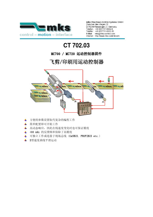
MC700 / MC720 运动控制器固件
飞剪/印刷用运动控制器
方便的参数设置取代复杂的编程工作 简单配置即可开始工作 高动态响应,因此在线速度变化时也可保证精度 400 kHz 的反馈频率保障了高精度 可独立工作或连接于现场总线 (CANBUS, PROFIBUS etc.) S型速度曲线平滑运动
固件 CT702.03需要支付授权费用,并且得到授权码以后才能使用!
2. 固件基本功能说明
2.1 介绍
固件 CT 702.03 适用于飞剪(轮切)系统、印刷和旋转辊模切等应用的控制。 固件 CT 702.03 本身针对飞剪的特定需求,以最大的精度、最高效率、最小机械冲击为目标而设 计。超短的控制周期和智能的运动曲线在任何条件下都可以提供卓越的性能。 控制器设置简单,所有的设定工作都可以在PC上使用 OS 5.0 软件完成。全部的相关操作参数可以 通过 RS232 / RS485 通讯或 CANopen 接口读、写。针对 PROFIBUS ,可以使用我们提供的 PB251 网 关。因此,可以使用PC、PLC或其它操作终端等多种方式进行远程操作。 此固件适用于剪切控制,同时也适用于局部印刷。本手册通常只提到“剪切”,读者可根..................................................................................................................................................1 2. 固件基本功能说明..................................................................................................................................1
MC700 用户手册 V1

M C700系列电动机保护器用户手册VER: 1.0感谢您购买纳宇电气有限公司的MC700系列电动机保护器。
在使用前请仔细阅读说明书中的各项内容,以便正确的使用。
不正确的使用,将造成运行不正常或引起故障和降低使用寿命。
本说明书应保存在实际最终使用的人手中,使用后务必妥善保管以便随时使用。
收到您订购的设备后,请开箱检查以下项目。
如发现产品存在问题或不符合您订购的设备时,请与代理商或公司服务部联系。
◆装箱内容本体:MC700一台可选附件:显示模块1台:MC820或MC830外部电流互感器3个:CT40II-500/1(额定电流1A,外置CT 500A配)漏电电流互感器1个:ZCT-30 或ZCT-100随机物品包括:合格证、用户手册本手册随大包装箱附送◆安全需知该装置必须有专业人员进行安装与检修在对该装置进行任何内部或外部操作前、必须切断输入信号和电源;提供给该装置的电参数需在额定范围内下述情况会导致装置损坏或装置工作的异常:●辅助电源电压超范围●电流输入极性不正确●带电拨通信插头●未按要求连接端子连线一.总介1.1产品简介MC700电动机保护器适用于380V低压系统,对电动机的过载、堵转、tE时间保护等故障予以保护,并具有测量、设备维护和运行记录、跳闸记录等重要信息,为现代化的设备管理带来很大方便。
采用模块化设计、产品体积小、结构紧凑、安装方便,在各种抽屉柜中可直接安装使用。
1.2 功能概述配置功能功能配置标准配置增选功能保护功能过载保护■阻塞过流保护■欠载保护■堵转过流保护■缺相/不平衡保护■起动超时保护■接地保护■外部故障保护■欠电压保护■过电压保护■漏电保护■欠功率保护■相序保护■t E时间保护■控制模式直接起动■任选一种双向起动双速起动星/三角起动自耦变压器降压起动保护模式测控模式通讯功能Modbus-RTU协议■Profibus 协议■DeviceNET协议■开关量输入8DI,功能可编程(内置电源)■开关量输出5DO,功能可编程■模拟量变送4~20mA信号输出■测量功能三相电流■接地电流■电流不平衡率■热容量■三相电压■频率■漏电电流■有功功率■功率因数■电能■参数查询与修改保护定值■起动参数■系统参数■开关量功能参数■统计与记录故障记录■报警信息■电机运行记录(起动、运行、停车、脱扣等)■SOE事件记录■实时时钟标准时钟■对时功能■控制功能本地/远程操作■上电自起动■欠压/失压自动重起动■接触器状态监视■故障复位■1.3 产品特性1.3.1 主回路额定绝缘电压Ui: AC690V额定冲击耐受电压Uimp: 6kV额定工作电流Ie:2A(0.5A~2A),5A(2A~5A),25A(5A~25A),63A(25A~63A),150A(63A~150A), 1A (外置CT) 额定电机工作电压Ue:AC380V/660V使用类别:AC-3、AC-4、AC-7b、AC-8a、AC-8b额定频率:50/60Hz额定工作制:不间断工作制额定限制短路电流Iq:50kA(AC660V)SCPD协调配合类型:2型配用SCPD型号:1A:NT00-4A, 2A:NT00-4A, 5A:NT00-6A25A:NT00-25A, 63A:NT00-63A,150A:NT00-160A脱扣级别:10A、10、20、30极数:3P短路保护:主回路应配备相应的短路保护元件电流检测最大穿线孔径:(Ie 0.5A~63A) 本体穿线Φ12mm(Ie 150A) 本体穿线Φ21.5mm(Ie 1A) 外接互感器 42mm×32mm 电压测量注意事项:从主回路接入时,要配备额外的保护元件1.3.2 控制回路额定控制电源电压(辅助工作电源电压Us):DC/AC85V-265V功耗:6VA/6W额定绝缘电压Ui: AC400V额定冲击耐受电压Uimp: 2.5kV开关量输出类型:继电器触点输出开关量输出数量:4常开 + 1常开常闭相应使用类别下额定工作电流Ie(A)和工作电压Ue(V):AC-15:250V/2A,DC-13:30V/2A约定发热电流Ith: 7A额定限制短路电流配合SCPD型号:NT00-10A开关量输出最大开断电流:7A/AC220V 0.3A/DC220V开关量输出最大开断电压:AC277V开关量输出最大开关容量:常开点:1680VA 常闭点:1200VA开关量输入电压标称值:24VDC 控制器提供开关量输入电流标称值:4mA开关量输入数量:8开关量输入冲击耐压:1kV 与其他回路间模拟量输出类型:4~20mA直流恒流输出模拟量输出最大负载:小于500欧姆模拟量输出短路电阻:有最大导线截面:4mm2,连接至接线端子最多1根导线 最小导线截面:0.5mm2,连接至接线端子最多2根导线 螺纹直径:3mm(十字或一字螺丝刀)拧紧力矩:0.5~0.6 N.m1.3.3 机械特性外壳防护等级:IP20外形尺寸:110mm×75mm×115mm安装方式:35mm导轨安装重量:小于 0.75kg1.3.4 环境特性工作温度:-20℃~60℃极限工作温度:-25℃~70℃存储温度:-30℃~80℃湿度:5%~95%(不结露)污染等级:2级;安装类别:Ⅲ阻燃性:符合 UL94 V-0海拔:小于2000米1.3.5 电磁兼容电磁兼容环境:环境A静电放电抗扰度:符合GB/T 17626.2-2006等级4 15kV 空气放电8kV 接触放电 射频电磁场辐射抗扰度:符合GB/T 17626.3-2006 等级3 10V/m电快速脉冲群抗扰度:符合GB/T 17626.4-2008 等级4 4kV浪涌(冲击)抗扰度:符合GB/T 17626.5-2008等级4 共模4kV 差模2kV射频场感应的传导骚扰抗扰度:符合GB/T 17626.6-2008 等级3 10V1.3.6 执行标准与认证GB/T 14048.4-2010 IEC60947-4-1:2009 低压开关设备和控制设备第4-1部分:接触器和电动机起动器机电式接触器和电动机起动器(含电动机保护器) CCC国家强制认证1.4 符号对照表符号含义Ie 控制器额定电流,对应所配电机的最大额定电流I g控制器输出触点的额定工作电流IΔnm外加漏电互感器的额定电流I r控制器的各种保护电流整定值t r控制器整定时间I r1电机额定电流Ue 电动机额定电压Pe 电动机额定功率U s控制器工作电压t 故障延时动作时间I 实际线路电流I m控制器最大分断电流K过载曲线速率Cc 电机热容量二.功能介绍2.1 测量项目范围精度电流10% Ie~120% Ie±0.5% 120% Ie~800% Ie±1%接地电流10% I r1~800% I r1±1%漏电电流10% IΔnm~120% IΔnm±1%电压100V~500V ±0.5%频率40Hz~65Hz ±0.05Hz功率因数-1~1 ±1%功率0~1000KW ±5%电能0~65535000kWh ±5%2.2 报警信息查询如保护的执行方式设置为报警方式时,如触发了保护条件,可在报警信息查询里查看。
Series 700 800 重型混合器说明书

We gave this series the capacity to drive long overhung mixer shafts without steady bearings. We gave it the stamina to withstand severe bending and high-torque loads imposed by fluid forces in the tank. And that’s something you can’t expect from the large general purpose drives not designed for mixing, which others use. We make shafts for 700/800 mixers larger and stronger. We size the bearings far in excess of AGMA requirements. We conduct extensive research to document the limits of shaft and impeller performance under all service conditions.As a result, you get longer service life with less maintenance. Y ou get our performance guarantee. Y ou get a mixer with an enviable track record, written by the thousands of 700/800 mixers produced in our state-of-the-art plant. Y ou’ll find our 700/800 mixers atop huge fermentation tanks in pharmaceutical production and in all manners of large scale chemical processing. Y ou’ll also find them in the dust and rock of minerals processing, as well as in the heavy sludge of waste treatment. Series 700/800 come in five case sizes, covering the range from 18.5kW to 1000kw (25HP to 1250HP). Both double and triple reduction drives are available, covering the full range of standard AGMA speeds from 230 rpm down to 11.4 rpm.PR OD U CT B E N E FITS AN D FEATU R E S• F ull Spectrum of Impellers to Optimize Results: Included are the A310 for flow-controlled applications, the A320 for high-viscosity requirements, the A315 for handling gas alone or gas and solids together, as well as the A6000 for applications requiring the special benefits of composite construction.• G uaranteed Performance: T ogether, we design your rugged 700/800 mixer, selecting impeller type, shaft length and other specifications to optimize process results. Then, we guarantee your Lightnin Mixer to perform the job for which it is recommended.• T ested 100%: Every large Lightnin mixer drive is tested under load on an advanced dynamometer. T est check gear contact patterns, noise readings, thermal data and lubrication. We welcome you to watch us test your mixer. Our goal always: Deliver factory-assembled, ready-to-go packaged units with interchangeable parts that will provide you the most efficient performance at the best possible cost.The Biggest, Heaviest Duty Standard Drives Made Specifically for MixingSPX FLOW, Inc. (NYSE:FLOW) is a leading manufacturer of innovative flow technologies, many of which help define the industry standard in the market segments they serve. From its headquarters in Charlotte, North Carolina, it operates a sales and support network, centers of manufacturing excellence, and advanced engineering facilities, throughout the world. Its cutting-edge flow components and process equipment portfolio includes a wide range of pumps, valves, heat exchangers, mixers, homogenizers, separators, filters, UHT, and drying technology that meet many application needs. Its expert engineering capability also makes it a premium supplier of customized solutions and complete, turn-key packages to meet the most exacting of installation demands.Incorporating many leading brands, SPX FLOW has a long history of serving the food and beverage, power and energy, and industrial market sectors. Its designs and engineered solutions help customers drive efficiency and productivity, increase quality and reliability, and meet the latest regulatory demands. In-depth understanding of applications and processes, state-of-the-art Innovation Centers, and advanced pilot/testing technology further assist in optimizing processes and reducing timescales to reliably meet production targets.T o learn more about SPX FLOW capabilities, its latest technology innovations and complete service offerings, please visit .A World Leader in Industrial Mixing since 1923, Lightnin has 90 years of unrivaled experience in industrial mixing technology, process knowledge, and technological innovation. Lightnin enjoys a global reputation for durable, long-lasting mixers, agitators, aerators, and flocculators for fluid process systems. We offer a full spectrum of impeller designs for diverse applications. In addition, we offer a worldwide service network, mixer repair, gearbox repair, and replacement parts programs. Look to Lightnin for knowledge, technology, and service excellence.3Flex ProtectionGears in all 800 series units like this one are protected from mixer shaft bending loads by the Lightnin hollow quill flex protection. Quill and shaft mixer are mounted on separate bearings. A torsionally resilient coupling transmits power from quill to mixer shaft, while isolating gearing from shaft flexure.Splash LubricationOn sizes up to 783/883, gears dipping in an oil sump provide a constant flow of oil to all surfaces.Covered For SafetyPersonnel are protected from rotating parts by guards that meet OSHA requirements. All mounting flanges are designed to ASME Unfired Pressure Vessel Code.Rugged Motor MountA heavy-duty channel base is the standard motor mount for Series 700/800.Quiet-Running GearsAll helical gears are carburized and ground. The highly efficient spiral bevel gear and pinion are match-lapped as a set to assure smooth, quiet operation.Beyond AGMABearings are sized far beyond AGMA requirements to minimize maintenance and provide long service life.A510: General Purpose New laser-designed impel-ler delivers true axial flow, high flow-per-horsepower, and can be custom-fit to your application.A320: High-Viscosity Fluid foil design reduces blend time by half anddelivers better axial motion for 50% power savingcompared to conventional pitch-blade turbines.A315: Gas-Liquids-Solids Improves yield by up to 50% in shear-sensitive processes such as fermentation. The A315 is the optimum impel-ler for applications involving mass transfer and solidssuspension.A6000: Low ViscosityFor flow-controlled applications in hostile environments. Main-tains flow and reduces power to 45% of conventional pitched-blade impellers. Structural composite is lightweight and extremely resistant to corrosion.TH E ORY OF OPE RATI ON:Features available on units up to 1000kW (1250HP)H I G H-E FFI CI E N CY I M PE LLE R S TO MATCH YOU R PR OCE S S N E E D S:Oil DamLeakage down the mixer shaft is positively prevented by an oil dam around the quill shaft.LightninLube™As part of our commitment to our Customers and their operations, SPX has introduced LightninLube™, a range of gear oil for our Lightnin Mixers. It is available to order with your new equipment or as a maintenance item throughout the life of your equipment.LightninLube is manufactured to AGMA Standard 8005-D94. Our synthetic oils are designed to give you a wide operating range and are available in ISO 100, ISO 150, ISO 220 and ISO 320 grades.Contact our Service department or your Sales Representative to discuss your needs.S U PP ORT F OR H EAVY M I X E R SLarge Series 700/800 mixers are optimally supported independently from the mixing tank. Mixers of closed tank configuration can be mounted on their own beams or on the plant floor above the tank. Either way, only a separate seal or stuffing box need be mounted on the tank and supported by it.Mounting on upper floor. Note how hydraulic lifts can simplify servicing the seal.TE CH N I CAL S E RVI CE SWith more than 90 years experience in the manufacture and supply of agitation equipment, we know what parts need to be on hand to support our customer base so that your downtime is minimized. The Lightnin brand after sales support teams are on call to offer advice, support on-site installation and commissioning, servicing of equipment, or super-vise and train your maintenance staff in best practice care of equipment.S E RVI CE S U PP ORT & R E FU R B I S H M E NT The equipment audit is specifically designed to identify potential mechanical problems before they occur. Using many forms of modern technology and drawing on our mixer manufacturing experience, our technicians can identify the onset of bearing and gear failures, misalign-ment and system problems without the need to interrupt production. Factory gearbox exchange and refurbishment programs offer a fastand cost-effective route to extending equipment life.USA13320 Ballantyne Corporate Place Charlotte, NC 28277United States of America +1 704 752 4400CH I NA7F Nanfung T ower 1568 Hua Shan Road Shanghai 200052 China P: +86 (21) 22085889UKOcean House, T owers Business Park Didsbury, Manchester M20 2L Y, UKP: +44 161 249 1170SPX FLOW, Inc. - Global locationsS PX FLOW, LLC - LI G HTN I N & PLE NTY M I X E R S135 Mt. Read Blvd.Rochester, NY 14611P: +1 (888) 649-2378 (MIX-BEST), (US and Canada) or +1 (585) 436-5550F: +1 (585) 436-5589E:********************•/lightninSPX FLOW, Inc. reserves the right to incorporate our latest design and material changes without notice or obligation.Design features, materials of construction, and dimensional data, as described in this bulletin, are provided for your information only and should not be relied upon unless confirmed in writing. Please contact your local sales representative for product availability in your region. For more information, visit . The green “” and “” are trademarks of SPX FLOW, Inc.LIG_700/800_B-656_US Version: 03/2019 COPYRIGHT © 2019 SPX FLOW, INC.For other Sales locations, click/lightnin\contacts\where-to-buy\or use your SmartPhone and the QR Code.。
MC-700系列质量流量控制器使用说明书

LN0427E2103E0Mass Flow Controller Instruction ManualSafety PrecautionsIncorrect handling may cause death or injury(1)Before connecting the fittings, check that no damage or defects are found on the fittings. Make connections properly and make sure that a leak test is conducted before actual operation to prevent fluid from leaking into the atmosphere (Hereafter, the measured fluid is called “gas” or “fluid”).(2) DO NOT apply any fluids corrosive to materials exposed to gas. Corrosion may cause fluid to leak into the atmosphere. Check the gas type to be used in advance. (3)This device is not designed as an explosion proof structure. DO NOT use this device in a place where explosion-proof structures are required. Doing so may cause fire or explosion.Incorrect handling may lead to medium or slight injury or may cause damage to, or loss of, facilities or equipment(1) Observe the precautions listed in the WARNING (above)(2) Strictly observe the electrical specifications. Not doing so may cause fire, damage to sensors or malfunction.(3) This device is not designed to be waterproof. DO NOT locate this device outdoors or in a place where it may be splashed with water. Doing so may cause fire, trouble, or malfunction of the device.(4) DO NOT modify this device. It may cause fire or other problems.(5)This device is not designed to handle hot swap. Please avoid attaching and removing the power supply connector and interface connector with the power switched on. Attachment and/or removal with the power on may result in failure of the device.(6) While a power supply is applied to MFC, ±15VDC must be applied simultaneously. If only +15VDC or -15VDC is applied, electronic circuits will become unstable and it may cause a malfunction of MFC.(7) This device is a precious device, please handle it carefully. Dropping down or handling it carelessly will cause damage. Please use assist instrument while moving or setting the device.(8)Regular maintenance is recommended for steady use of this device (Recommended proofreading frequency is once a year).1. IntroductionThis manual explains basic operation of the MC-700 series (Hereafter, it is called"MFC"). Please read through this manual and other separate volumes (Digital Interface Manual, Special Function Manual, Command Chart) carefully to familiarize yourself with the features of this device.2. SummaryThis device is the mass flow controller with the function of switching differentkinds of gas and flow rate (Hereafter called "variable function" or "VR"). By using the 3 rotary switches on the MFC, the gas type and flow rate can be changed. The rotary switches are placed conveniently on top of the MFC unit so thatadjustments can be made accordingly even after the unit is set in position. For old models, stocking MFC for each of gas and flowrate was necessary because only one spec is available to one MFC, and MC-700 can reduce your stocking because it can be used for more than one spec with one MFC.3. FeaturesThe MFC has the following features.(1) LINTEC’s proprietary ambient temperature compensation type flow sensor.·The influence of ambient temperature is small due to the sensor temperature control following the ambient temperature.·Since the temperature distribution of the sensor is constant, high-speed response is possible.(2) Gas type and flow rate setting can be changed by using the 3 switches on the mass flow controller unit.(3) Digital interface (RS-485) is standard equipment and the maximum of 32 MFCs could be connected together with daisy chain. (Option: Digital interface RS-232C is possible)(4) Small structure of dead volume using diaphragm valve.(5) Stainless steel 316L is used because of good corrosion resistance and seal ability. (6) Particule-free structure(7) RoHS compliant, CE conformity4. StructureThe MFC consists of sensors, bypass, valves, and a microcomputer for signalprocessing. A digital PID feedback control system controls the valve action so that flow rate output from the sensor agrees with flow rate setting value.5. Specification / DimensionsNote 2) The value at the time of shipping. This may change with gas type and flow rate setting. · Connect the MFC to the ground.(2) Dimensions6. Ordering informationMC-710 MC - 4VR2 A0A0A0 - 06 - N2 - 1.5SLM [1] [2] [3] [4] [5] [6] [7][1] Model: MC: Mass Flow Controller Series MC-710 MC-720 MC-730 [2] Valve operation mode · Internal surface treatmentNO: Normally opened valve / No treatment NC: Normally closed valve / No treatmentMO: Normally opened valve / Precision polishing MC: Normally closed valve / Precision polishing [3] Fitting4VR2: 6.35VCRType 124mm4VR1: 6.35VCRType 106mm (option) 4SWL: 6.35SWLType 127mm (option) ※ Please consult us for other fitting types. [4] Other optionsDefault settings is labeled “A 0A0A0”, please consult for more information. [5] VR Number [6] Gas type[7] Full scale flow rate and unit: SCCM(0°C standard), SLM(0°C standard)7. Connection(1) Analog interface connectorMounted connector : D-Sub 9 pin(male)Note4)Pin No.[4],[7]and No.[8] are connected internally in MFC.Wirings should be done as shown below in order to remove the effect of potential difference among the COMMON.Do not connect. Flow rate setting signal COMMON[8], Flow rate output signal[7], and Power supply COMMON[4] in the power supply unit.(2) Digital interface connectorMounted connector : RJ-45 Modular jack Pair connector : RJ-45 Modular plugR0 or R1. Refer to the attached sheet of digital interface instruction manual for connection. Note6)[Power OUT] means the power output of RS-1 interface and it is not applicable for connections to other machines without R1 option.· RS-1 is a discontinued product. Therefore, MC-3000E series / MC-2000 series can be replaced with MC-700 series including option.8. Alarm functionsThe MFC has two types of alarm functions built in. In addition, alarm status can be confirmed using both digital communication (alarm output from the digital connector) and an LED located on top of the body of the MFC. As alarm settings can only be changed using digital communication, please carry out necessary changes using this method. For 9. Software switch (factory shipped value)This MFC is provided with a software switch for operation mode setting. Beforeoperation, input the necessary data for various functions by using the digital interface.· If the zero adjust button on the top of the MFC is pressed and held for over 5 seconds, the communication protocol is reset to default.10. Operation (1) Procedure1)This product is packed in a clean room before shipment. Please break theseals in a clean room after taking it out of its box.2) Check the gas type and flow rate and check the direction of the gas flow and the MFC before installation.3) Check for gas leaks from the tubing with a helium (He) leak detector. 4) Connect the interface connectors according to the Connector table.5) Power requirements are +15VDC:120mA and -15VDC: 50mA. Check the voltage, polarity, and capacitance of the power supply voltage.6) Turn on power supply and let the equipment warm up for at least 5 minutes (Recommended time: 30min).7)Adjust the zero point by pressing the zero adjustment, switch located on the top of the MFC. Before zero-point adjustment, check that gas is not being supplied and the device was warmed up for 30 minutes or more in order to ensure sensor stability.8)Input the flow rate setting signal and supply gas with required differential pressure to the MFC. The MFC will begin to control the gas flow in proportion to the preset voltage. Full-scale voltage is 5VDC. Maximum input voltage is ±15.5VDC.9) When the output flow rate signal is used, the tolerance voltage of the external device should be more than ±15.5VDC. When it’s conne cted the output valve may be within the range of the maximum voltage ±15.5VDC. 10) Complete shut-off cannot be achieved with the mass flow controller. If complete shut-off is desired, a shut-off valve should be installed.11) When a highly reactive gas is used, thoroughly purge all foreign matter from the tubing and the MFC before operation.12) When contaminated gas is used, install a filter at the equipment inlet.13)Use the MFC within the range of the operating temperature (15 to 35°C), and keep it at the same temperature with the gas. If used in any environment that does not meet the above-mentioned requirements, the flow rate cannot be measured accurately and the device may fail.14)Do not switch the power supply on and off within one second. It may cause failure.(2) Valve control signalThe MFC features a forced valve open/close input function.The connector pin No.1 is used to input the internal valve open/close signal. By inputting this signal, a forced opening/closing of the internal valve can be performed without depending on the value of the flow rate preset signal. When +15VDC is input: fully open When –15VDC is input: fully closed(3) Variable Range functionBy using one device of MFC, it is possible to modify multiple flow rate ranges and gas types. To modify the flow rate or the gas type, refer to the following VR corresponding chart or the calculation formula, and modify the variable range by the rotary switches (for analog control) or digital communications (for digitalcontrol).[Formula](standard flow rate) ÷ (desired flow rate) × (conversion factor) By using this function, the flow rate and gas type may be changed, however if a different gas is to be used, please consider the properties of the gas and confirm the responsiveness before usage. Also, in the case that the gas may cause debris or particle, please refrain from using it. If you have any questions of conversion factor, please contact us.(4) Digital interfaceThe MFC features the RS-485 or RS-232C (Note 5) digital interfaces. Manyspecial functions can be employed using the digital interfaces.Please refer to other manuals (Digital Interface Manual, Special FunctionManual Command Chart).11. Product warranty(1) PeriodThis product is guaranteed for a period of 1 year from date of shipment. Defects are repaired according to the following regulations.(2) ScopeWarranty coverage is restricted to this product only. Any other damage caused by an is not covered.(3) Disclaimer factsThe following repairs are not covered by the warranty:1) Failure caused by by-product of fluid used2) Failure caused by misuse (including careless operation) or incorrect repair ormodification3) Failure caused by dropping after purchasing4) Failure caused by a natural disastersEven if the warranty period is still in effect, the following items may not be repaired.1) In case of the product is returned with fluid remaining inside2) In case of what kind of fluid was not informed used on the productThe MFC is a precision instrument. Control may become unstable if electric noise, temperature change of fluid, pulsation of fluid pressure etc. occurs. Please be forewarned.This instruction manual is subject to revision without noticehttp://www.lintec-mfc.co.jpCorporate Headquarters4-1-23 Sekinotsu, Otsu City, Shiga Pref. 520-2277, JapanTEL.+81-(0)77-536-2210 FAX. +81-(0)77-536-2215Tokyo Branch Office3F Hattori Build., 4-30-14 Yotsuya Shinjyuku-ku Tokyo 160-0004, JapanTEL. +81-(0)3-5366-2801 FAX. +81-(0)3-3341-3513。
MC700系列说明书

MC700系列智能多媒体控制系统Intelligent Multimedia Control System(适用于MC700系列机型)用户手册User’s Manual**请在安装使用前认真阅读本说明书**尊敬的用户:感谢您选购我们生产的MC700系列多媒体中央控制器。
该产品具有外观设计小巧高档大方;使用简单方便;功能强大;扩展能力极强;可直接外接其他厂家的设备;三个可编程232口最多可同时控制三个不同厂家的投影机或两个不同矩阵;可对各接口重新定义和单独控制;投影机一键切换;投影幕自动升降;开机即是电脑画面等等多种实用功能。
为了您能安全地使用本设备,发挥其最大的功能,强烈建议在安装使用前先仔细阅读本说明书。
若有任何技术问题或对产品的意见和建议,请与本公司技术服务部联系。
联系方法如下:电话:(020)33534881 61281788传真:(020)61281788地址:广州市天河软件园建工路9号4楼邮编:510600E-mail:laitong@http://特别提醒:1. 在使用本系统的时候,严禁在开机时对各个部件进行插拔(特别是通讯口及VGA接口,这可能会人为损坏设备)。
2. 本控制器为智能开关设计,在雷雨天气或长时间不使用时,请关闭电源总闸。
3. 本控制器内有强电模块,严禁带电自行维修。
目录一、使用说明 (5)1. 中控简介 (5)2. 中控组成 (5)二、硬件连接 (7)1. 连线说明 (7)2. 中控内部跳线说明 (10)三、系统设置 (11)1. 系统通讯协议 (12)2. 开机状态设置 (14)3. 开关机流程设置 (15)4. 开关延时设置 (16)5. 投影机设置 (17)6. 红外学习 (19)7. 按键面板设置 (20)8. 其他设置 (23)四、常见故障处理 (24)1. 按控制面板“系统开”无法开机 (25)2. 红外学习不成功或显示成功却不能遥控 (25)3. 有些设备红外遥控不灵 (25)4. 投影机开关切换不灵 (25)5. 关投影机出问题 (26)一、使用说明1. 中控简介智能多媒体控制系统为现代化的会议中心、电化教室及家居提供了最佳的解决方案。
MC-700说明书
M C-700说明书(总5页) -CAL-FENGHAI.-(YICAI)-Company One1-CAL-本页仅作为文档封面,使用请直接删除目录一.概述 (1)二.主机面板图 (1)三.操作键说明 (2)四.主机面板窗口显示 (4)五.功能与使用方法 (4)语音抢答模式 (4)普通抢答模式 (5)按钮指示灯状态 (5)连接计算机操作 (6)后面板接口图 (7)六.注意事项……………………………………………7一.概述:本着更智能的开发理念,公司近期成功推出新一代MC-700型无线智能抢答器。
此款无线抢答器,既可以单机使用,又可以连接电脑使用。
相比市面上的无线抢答器优势巨大。
本产品以一种全新的外观问世,机身符合于人体工学设计。
操作也更加简便。
本产品采用Cortex-M3内核高速处理器,各种识别、判断均由机器自动完成,极大的减少操作人员的工作量。
设备内部语音、语调、语速都是依据多年的比赛经验精心调制,从而使得比赛始终在热烈的氛围中进行,目前产品在各大银行、国家电网、电视台、学校、企业等单位得到广泛的应用并得到一致好评。
二.主机面板图:三.操作键说明:1. 《开始》键:此按键为抢答开始的启动按键,在当前抢答模式下,按下此键代表抢答开始。
如果不连接电脑情况下,此机器提供两种抢答模式:语音模式和普通模式;(连接电脑使用时,软件提供四种抢答模式)A.语音模式:主持人读完题后按下《开始》键,机器发出“3、2、1”的抢答令,并开始有效抢答倒计时,当有选手抢答后,机器自动判断并语音报出“* *台犯规”或“请* *台回答”。
B.普通模式;按下《开始》键,机器自动进行有效抢答倒计时,当选手抢答后,机器发出“嘀嘟”的提示音,在此模式下,机器只将最快抢答选手的台号显示出来,不做犯规与否的判断,选手是否犯规由主持人来判断。
2.《开始》键左侧《上》《下》键:此键为有效抢答时间设置键,设置范围为0~999秒,比赛开始前可以通过调节此键来设置有效抢答时间。
Philips MCB700 数字音频广播微音响系统说明书

PhilipsMicro Hi-Fi SystemDigital Sound from DAB StationsEnjoy superb clarity with a built-in DAB tuner with this Micro system. With a mirror-finished centre-unit that adds a touch of stylishness to any interior and wood-finishedspeakers that deliver high quality sound.Enjoy digital quality DAB radio•Tune into digital-quality radio stations•DAB and FM compatible for a full radio experienceUnlimited listening pleasure•Play MP3/WMA-CD, CD and CD-RWEnrich your sound experience•Digital Sound Control for optimised music style settings•Dynamic Bass Boost for deep and dramatic sound•Loudness for bass and treble enhancement•2 x 25 W RMS/2 x 50 W Music PowerDesign that blends into your interior(s)•High-end component design with stand•Elegant wood-finished speakers•High-quality remote control for comfortable useHighlightsDAB and FM compatibleDAB (Digital Audio Broadcasting) digital radio is a new way of broadcasting radio, in addition to FM analogue transmission, via a network of terrestrial transmitters. It provides listeners with more choices and information delivered in clear, crackle-free sound quality. The technology allows the receiver to lock on to the strongest signal it can find. With DAB digital stations there are no frequencies to remember, and sets are tuned by station name,so there is no retuning on the move.Digital Sound ControlDigital Sound Control offers you a choice ofpre-set Jazz, Rock, Pop and Classical controlsyou can use to optimise the frequency rangesfor different musical styles. Each mode usesgraphic equalizing technology to automaticallyadjust the sound balance and enhance the mostimportant sound frequencies in your chosenmusic style. Ultimately, Digital Sound Controlmakes it easy for you get the most out of yourmusic by precisely adjusting the sound balanceto match the type of music you are playing.Dynamic Bass BoostDynamic Bass Boost maximises your musicenjoyment by emphasising the bass content ofthe music throughout the range of volumesettings - from low to high – at the touch of abutton! Bottom-end bass frequencies usuallyget lost when the volume is set at a low level.To counteract this, Dynamic Bass Boost can beswitched on to boost bass levels, so you canenjoy consistent sound even when you turndown the volume.Loudness for bass and trebleIn the sound spectrum, high and lowfrequencies are relatively less audible to humanears - especially at low volumes. With theLoudness feature activated, the bass and treblewill be amplified so you can savour a morebalanced sound perception overall.SpecificationsSound•Output Power: 2 x 25 watts RMS/2 x 50 watts music power•Sound Enhancement: Loudness, Digital Sound Control 4 modes, Dynamic Bass Boost Loudspeakers•Main Speaker: 2-way, 4" woofer, Bass Reflex Speaker System, Speaker grilles detachable Audio Playback•Playback Media: WMA-CD, MP3-CD, CD-RW, CD-R, CD•Disc Playback Modes: 20-Track Programmable, Repeat/one/all/programme, Shuffle Play •Loader Type: Motorised, TopTuner/Reception/Transmission•Auto digital tuning•Station presets: 20•Tuner Bands: FM Stereo•DAB: Info display, Menu, Smart Scan, Band III •RDS: Programme Type, Radio Text, Station Name Connectivity•Aux in: 2 x (L/R)/RCA•Headphones: 3.5 mmConvenience•Alarms: CD Alarm, Sleep timer•Clock: On main display•Display Type: VFD display•Eco Power Standby: 1 wattAccessories•Included Accessories: Control cable, FM antenna, DAB antenna•Remote control: 38-key with Lithium battery •Quick start guide: English•User Manual: English•Warranty Card: World Wide Warranty leaflet Dimensions•Set dimensions (W x H x D): 208 x 156 x 268 mm •Main speaker dimensions (W x H x D):145 x 230 x 215 mm•Packaging dimensions (W x H x D):475 x 275 x 330 mm•Weight incl. Packaging: 11.5 kgIssue date 2009-07-17 Version: 2.0.412 NC: 9073 100 13513 EAN: 87 10895 98035 7© 2009 Koninklijke Philips Electronics N.V.All Rights reserved.Specifications are subject to change without notice. Trademarks are the property of Koninklijke Philips Electronics N.V. or their respective owners. 。
MC700系列说明书
MC700系列智能多媒体控制系统Intelligent Multimedia Control System(适用于MC700系列机型)用户手册User’s Manual**请在安装使用前认真阅读本说明书**尊敬的用户:感谢您选购我们生产的700系列多媒体中央控制器。
该产品具有外观设计小巧高档大方;使用简单方便;功能强大;扩展能力极强;可直接外接其他厂家的设备,三个可编程232口最多可同时控制三个不同厂家的投影机或两个不同厂家矩阵;可对各接口重新定义和单独控制;投影机一键切换;投影幕自动升降;开机即是电脑画面等等多种实用功能。
为了您能安全地使用本设备,发挥其最大的功能,强烈建议在安装使用前先仔细阅读本说明书。
若有任何技术问题或对产品的意见和建议,请与本公司技术服务部联系。
联系方法如下:电话:(020) 33534881 61087188传真:(020)61087188-8002地址:广州市天河软件园建工路9号4楼南区A1邮编:510665EMAIL:laitong@http://特别提醒:1.在使用本系统的时候,严禁在开机时对各个部件进行插拔(特别是通讯口及VGA接口,这可能会人为损坏设备)。
2 本控制器为智能开关设计,在雷雨天气或长时间不使用时,关闭电源总闸。
3.本控制器内有强电模块,严禁带电自行维修。
4.因中控本身已做好接地处理,为有效保护中控及设备,请在强电输入部分做好接地措施!目录一、使用说明 (4)1中控简介 (4)2、中控组成 (4)二、硬件连接 (5)1.连线说明 (5)三、系统设置 (7)1、系统通讯协议 (7)2、开机状态设置 (10)3、开关机流程设置 (10)4、开关延时设置 (11)5、投影机设置 (12)6、红外学习 (13)7、按键面板设置 (14)8、其他设置 (17)四.常见故障处理 (18)1、通过控制面板“系统开”无法开机 (18)2、红外学习不成功或显示成功却不能遥控 (18)3、有些设备红外遥控不灵 (19)4、投影机打不开 (19)5、中控与电脑连接失败 (19)一、使用说明1中控简介智能多媒体控制系统为现代化的会议中心、电化教室及家居提供了最佳的解决方案。
RocketLinx MC7001 工业级以太网到光纤媒体转换器说明书

Quick Installation GuideROCKET LINX MC7001Industrial Ethernet to Fiber Media ConverterThe RocketLinx MC7001 industrial Ethernet to fiber media converter conforms to IEEE 802.3 and IEEE 802.3u standards with one 10/100BASE-TX and one 100BASE-FX Fast Ethernet fiber port. The MC7001 features a slim and compact industrial design to save DIN rail space for compact installations. In order to perform under harsh environments, the MC7001 is housed in an industrial-grade aluminum case with IP31 standard protection.The 4-Pin DIP switch configures the MC7001 to operate in switch mode or pure converter mode.Package ChecklistMC7001 industrial media converter Quick Installation GuideMounting the RocketLinx MC7001Mount the DIN rail clip on the rear of the MC7001 to the DIN rail.Grounding the RocketLinx MC7001There is a grounding screw on the bottom side of the MC7001. As shown in the picture, connect the ground screw of the MC7001 to a grounding surface to ensure safety and prevent noise.IntroductionThe power input provides polarity reverse protection to avoid system damage. 1. Insert the positive and negative wires into the V+ and V- contact on the terminal block connector.2. Tighten the wire-clamp screws to prevent the power wires from being loosened.Note: The recommended working voltage is 24VDC (18-32VDC) or 18VAC (18-27VAC)Wiring the Power Inputsavoid system damage. 8-32VDC) or 18VAC (18-27VAC)Accepts 12-24AWG wire.The MC7001 providespolarity reverse protectionV-V+h mode or pure.RocketLinx MC7001Connecting to the Network1. Connecting the Ethernet Port: Connect one end of an Ethernet cable into the RJ45 port of the MC7001, and the other end is attached to a networking device. The RJ45 port supports Auto MDI/MDIX functionality. The TP LED will turn on and flash to indicate RJ45 port’s link and activity.2. Connecting the Fiber Port: Connect the fiber port on your MC7001 to another fiber Ethernet device, by following the figure below. Wrong connection or fiber cable type will cause the fiber port to not function properly.This is a Class 1 Laser/LED product. Don't stare into the Laser/LED Beam.Cable Wiring(SC to SC)RX A TX BTX A RX B A B3. For different link distances, the MC7001 provides Multi-Mode fiber and Single-Mode fiber models. The table below illustrates fiber transceiver specifications. The fiber connector is a standard connector or square connector (SC). To ensure your fiber converter cantransmit/receive data between the 2 nodes, the attenuation of the optical fiber cable should not exceed the fiber converter’s Link Budget.Mode Cable Type Wavelength Transmit Power(min.)TransmitPower (max.)Receive Sensitivity (max.)Receive Sensitivity (min.)Min. Launch Power –Max. Receive SensitivityDistance(km)Multi 50/125um 62.5/125um1310nm -20dBm -14dBm -31dBm 0dBm 11dBm2km Note (below)Single 8-10/125um 1310nm -15dBm -8dBm -34dBm -8dBm 19dBm30kmNote: In the IEEE standard, it suggests the available transmission distance is 2KM for 62.5/125um fiber optical cable in 1310nm wave length. Actually, the attenuation of Multi-Mode 62.5/125um optical fiber cable is 1.5dBm/km and the maximum link distance can up to 4 to 5km.IEEE organization recommends maximum optical fiber cable distances as defined in thefollowing table:Standard Data Rate (Mbps) Cable Type IEEE StandardDistance 100Base-FX 100 1310nm, 50/125um or 62.5/125umMulti-Mode optical fiber cable2km100Base-SX 100 850nm, 50/125um or 62.5/125umMulti-Mode optical fiber cable300m1000Base-SX 1000850nm, 50/125umMulti-Mode optical fiber cable850nm, 62.5/125umMulti-Mode optical fiber cable550m220m1000Base-LX 10001310nm, 50/125um or 62.5/125umMulti-Mode optical fiber cable1310nm, 9/125umSingle-Mode optical fiber cable550m5km1000Base-LH 1000 1550nm,9/125umSingle-Mode optical fiber cable70kmThe following table provides information about optical fiber cable attenuation:DIP Switch SettingNote: After adjusting the DIP-switch, reboot the MC7001 to activate the new settings.LED FunctionsComtrol Customer Service。
德国MOTRONA飞剪控制器MC700 英文版简明手册

The output signal always has TTL level with consideration of the RS422 standard, and the maximum output frequency is 400 kHz.
MC70001c_de.doc / Sep-13
Page 4 / 14
A
3 7 8 4 9 5
B
1
A
2 6
A
3 7 8 4 9 5
B
1
A
2 6
A
GND 3 7 8 4 9 5 4x SUB-D-9 (male on unit site)
Hale Waihona Puke Z Z Encoder 1
B
Z Z Encoder 2
B
Z Z Encoder 3
B
Z Z Encoder 4
B
a) Encoder 1 - Encoder 4 In In
_
+
1 2 3
+
24VDC Power Supply
2 3 1
_
Hint:
When mounting the unit to DIN rail, the housing will get earth potential by the rear mounting brackets and you can omit the additional earthing connection (3)
GND
5 9 4 8 3
A
2 7
A
1 6
B
SUB-D-9 (female on unit site) 33R 33R
MCM700 用户手册说明书
USB1.1), tarjetas de memoria (necesita un lector de tarjetas adicional para ser operativo con este sistema
inalámbrico).
1 Introduzca el conector USB del dispositivo USB en la toma
4
Pulse CLOCK para confirmar el ajuste horario.
Paso C Disfrutar
Reproducción de un disco 1
Pulse SOURCE en la parte superior del sistema para seleccionar CD o pulse DISC en el control remoto.
1
lugar antes de continuar con el siguiente procedimiento.
En el modo de espera, pulse y mantenga pulsado CLOCK en el control remoto.
2
Cuando los dígitos horarios destellen, pulse VOLUME-/+ en el aparato o pulse VOL+/- en el control remoto para ajustar las horas.
PDCC-JS/JW-0711
3
Pulse CLOCK de nuevo y los dígitos de los minutos destellan. Pulse VOLUME-/+ en el aparato o pulse VOL+/- en el control remoto para ajustar los minutos.
飞利浦 MCD700 MCL707 使用说明

DVD Micro SystemMCD700MCL707MCD700MCL707l ilIndexEnglish------------------------------------------------4Français--------------------------------------------32Español---------------------------------------------6190Manufactured under license from Dolby Laboratories.“Dolby”,“Pro-logic” and the double-D symbol are trade-marks of dolby Laboratories.MANUFACTURED UNDER LICENS E FROM DIGITALTHEATER S YS TEMS, INC. US PAT. NO 5,451,942,5,956,674, 5,974,380,5,978,762 AND OTHER WORLD-WIDE PATENTS ISSUED A ND PENDING.“DTS” AND “DTSDIGITAL SURROUND” ARE RESISTERED TRADEMARKSOF DIGITAL T HEATER SYSTEMS,INC.COPYRIGHT 1996,2000 DIGITAL THEATER S YS TEMS, INC.ALL RIGHTSRESERVED.This product incorporates copyright protection technologythat is protected by method claims of certain U.S.patentsand other intellectual property rights owned by MacrovisionCorporation and other rights e of this copyrightprotection technology must be authorized by MacrovisionCorporation,and is intended for home and other limitedviewing uses only unless otherwise authorized byMacrovision Corporation.Reserve engineering or disassem-bly is prohibited.一般事項特點 (92)隨機配件 (92)環保資訊 (92)安裝 (92)維護保養 (92)連接連接揚聲器 (93)連接天線 (94)連接控制電纜 (94)連接電視機 (94)連接電源線 (94)連接其它設備 (95)功能概述DVD 播放機與功率擴大器...........................96~97遙控器.....................................................................97~98準備步驟一:裝入遙控器電池 (99)使用遙控器操作本系統步驟二:設定電視機 (99)選擇與電視機對應的制式步驟三:設定所需的語言 (100)設定菜單顯示語言設定聲音、字幕和碟片選單語言基本功能開啟或關閉系統 (101)音量控制 (101)音效控制 (101)DBB (動態低音增強)DSC (數碼音效控制)LOUDNESS (響度)調整顯示屏亮度 (101)目錄光碟操作適合播放的光碟類型 (102)播放光碟 (102)使用光碟目錄................................................102~103基本播放控制................................................103~104暫停播放 (DVD/VCD/CD/MP3/WMA)選擇曲目、章節或標題 (DVD/VCD/CD/MP3/WMA)從上次停止位置恢復播放 (DVD/VCD/CD/MP3/WMA)縮放 (DVD/VCD/JPEG)重複 (DVD/VCD/CD/MP3/WMA)重複 A-B (DVD/VCD/CD/MP3/WMA)慢動作 (DVD/VCD)編程 (圖片CD 無此功能)向前或向後搜索 (DVD/VCD/CD/MP3/WMA)根據時間、章節或歌曲名稱搜索 (DVD/VCD/CD/MP3/WMA)播放過程中的資訊顯示 (圖片CD 無此功能)光碟特殊功能................................................104~105播放標題 (DVD)攝影機角度 (DVD)更換音頻語言(僅限以多種語言錄製的DVD)更換聲道 (僅限 VCD)字幕 (DVD)播放 MP3/WMA/JPEG 圖片CD (105)播放 MP3/ WMA 光碟 (105)一般操作播放選擇播放 JPEG 圖片光碟 (105)一般操作播放選擇JPEG 圖片光碟特殊功能 (106)預覽 (JPEG)圖片縮放 (JPEG)幻燈片播放模式 (JPEG)多角度播放 (JPEG)目錄系統菜單選項基本操作 (1074)通用設定頁.....................................................107~109電視機顯示顯示語言屏幕保護音頻設定頁 (109)SPDIF 設置杜比數碼設定3D 處理HDCD輸出動態壓縮視頻設定頁 (110)色差視頻電視機模式畫質設定初期設定頁 (111)年齡控制缺省設置密碼設定頁 (111)密碼模式密碼其它功能電台接收 (112)調諧選台預設電台收聽預設電台改變調諧頻階 (112)設置時鐘 (112)設置關機或開機計時器 (113)關機計時器設置開機計時器設置技術規格 (114)故障排除...............................................115~116辭彙 (117)安裝●將本機放置在平坦、堅固、穩定的平面上。
PWC_MC700_主控模块_说明书_V01.33
6. 参数设定.....................................................................................................................................7 6.1 菜单介绍.............................................................................................................................7 6.1.1 菜单结构树形图.............................................................................................................7 6.1.2 进入菜单.........................................................................................................................8 6.1.3 选择一个参数值.............................................................................................................9 6.1.4 输入一个参数值...........................................................................................................10 6.1.5 查看一个参数值...........................................................................................................10 6.1.6 退出菜单....................................................................................................................... 11 6.2 通信参数菜单_COM....................................................................................................... 11 6.2.1 CAN 通信波特率 .......................................................................................................... 11 6.2.2 COM1 通信地址............................................................................................................ 11 6.2.3 COM1 通信波特率........................................................................................................12 6.2.4 COM2 通信地址............................................................................................................12 6.2.5 COM2 通信波特率........................................................................................................12 6.2.6 RS485 通信地址............................................................................................................13 6.2.7 RS485 通信波特率........................................................................................................13 6.3 错误提示菜单_ALARM ..................................................................................................13 6.3.1 CAN 通信错误提示使能_E-131...................................................................................13 6.3.2 COM1 通信错误提示使能_E-130 ................................................................................14 6.3.3 COM2 通信错误提示使能_E-133 ................................................................................14 6.3.4 COM3(RS485)通信错误提示使能_E-134....................................................................14 6.3.5 在 PC 机通信错误时自动复位输出使能_E-Pcr ..........................................................15 6.4 输入功能选择菜单_ioSET...............................................................................................15
Bose Bass Module 700 重要安全说明说明书

B A S S M O D U L E700Please read and keep all safety, security, and use instructions.Bose Corporation hereby declares that this product is in compliance with the essential requirements andother relevant provisions of Directive 2014/53/EU and all other applicable EU directive requirements. Thecomplete declaration of conformity can be found at:This product product conforms to all applicable Electromagnetic Compatibility Regulations 2016 and all other applicable UK regulations. The complete declaration of conformity can be found at:Bose Corporation hereby declares that this product is in compliance with the essential requirements perRadio Equipment Regulations 2017 and all other applicable UK regulations. The complete declaration ofconformity can be found at:Important Safety Instructions1. Read these instructions.2. Keep these instructions.3. Heed all warnings.4. Follow all instructions.5. Do not use this apparatus near water.6. Clean only with a dry cloth.7. Do not block any ventilation openings. Install in accordance with the manufacturer’s instructions.8. D o not install near any heat sources such as radiators, heat registers, stoves, or other apparatus (includinga mplifiers) that produce heat.9. P rotect the power cord from being walked on or pinched particularly at plugs, convenience receptacles, and thepoint where they exit from the apparatus.10. Only use attachments/accessories specified by the manufacturer.11. Unplug this apparatus during lightning storms or when unused for long periods of time.12. R efer all servicing to qualified personnel. Servicing is required when the apparatus has been damaged in anyway, such as power-supply cord or plug is damaged, liquid has been spilled or objects have fallen into thea pparatus, the apparatus has been exposed to rain or moisture, does not operate normally, or has been dropped.WARNINGS/CAUTIONSThis symbol on the product means there is uninsulated, dangerous voltage within the product enclosure that may present a risk of electrical shock.This symbol on the product means there are important operating and maintenance instructions in this guide.This product contains a tempered glass surface. Use caution to avoid impact. In the event of breakage, use care in handling broken glass.This product contains magnetic material. Consult your physician on whether this might affect yourimplantable medical device.• To reduce the risk of fire or electrical shock, do NOT expose this product to rain, liquids or moisture.• Do NOT expose this product to dripping or splashing, and do not place objects filled with liquids, such as vases, on or near the product.• Keep the product away from fire and heat sources. Do NOT place naked flame sources, such as lighted candles, on or near the product.• Do NOT make unauthorized alterations to this product.• Do NOT use a power inverter with this product.• Do NOT use in vehicles or boats.• The speaker wire and interconnect cables included with this system are not approved for in-wall installation. Please check your local building codes for the correct type of wire and cable required for in-wall installation.• Where the mains plug or an appliance coupler is used as the disconnect device, the disconnect device shall remain readily operable.仅适用于 2000m 以下地区安全使用Use at altitude less than 2000 meters only.• Due to ventilation requirements, Bose does not recommend placing the product in a confined space such as in a wall cavity or in an enclosed cabinet.• The product label is located on the bottom of the product.NOTE: This equipment has been tested and found to comply with the limits for a Class B digital device, pursuant to Part 15 of the FCC Rules. These limits are designed to provide reasonable protection against harmful interference in a residential installation. This equipment generates, uses, and can radiate radio frequency energy and, if not installed and used in accordance with the instructions, may cause harmful interference to radio communications. However, there is no guarantee that interference will not occur in a particular installation. If this equipment does cause harmful interference to radio or television reception, which can be determined by turning the equipment off and on, the user is encouraged to try to correct the interference by one or more of the following measures:• Reorient or relocate the receiving antenna.• Increase the separation between the equipment and receiver.• Connect the equipment into an outlet on a circuit different from that to which the receiver is connected.• Consult the dealer or an experienced radio/TV technician for help.Changes or modifications not expressly approved by Bose Corporation could void the user’s authority to operate this equipment.This device complies with part 15 of the FCC Rules and with ISED Canada license-exempt RSS standard(s). O peration is subject to the following two conditions: (1) This device may not cause harmful interference, and (2) this device must accept any interference received, including interference that may cause undesired operation.This device complies with FCC and ISED Canada radiation exposure limits set forth for general population.This equipment should be installed and operated with a minimum distance of 20 cm between radiator and your body. This transmitter must not be co-located or operating in conjunction with any other antenna or transmitter.This device for operation in the 5150 - 5250 MHz is only for indoor use to reduce the potential for harmful interference to co-channel mobile satellite systems.Receiver Category = 2CAN ICES-3(B)/NMB-3(B)For Europe:Frequency bands of operation 2400 to 2483.5 MHz, 5150 to 5350 MHz, and 5470 to 5725 MHz.Maximum transmit power less than 20 dBm EIRP.Frequency band of operation 5725 to 5850 MHz.Maximum transmit power less than 14 dBm (25mW) EIRP.Maximum transmit power is below regulatory limits such that SAR testing is not necessary and exempt per applicable regulations.This device is restricted to indoor use when operating in the 5150 to 5350 MHz frequency range in all EU Member States listed in the table.BE DK IE UK(NI)FR CY SK HU AT SE BG DE PT EL HR LV LT MT PLCZ EE FI ES IT RO LU NL SIThis symbol means the product must not be discarded as household waste, and should be delivered to anappropriate collection facility for recycling. Proper disposal and recycling helps protect natural resources,human health and the environment. For more information on disposal and recycling of this product, contact your local municipality, disposal service, or the shop where you bought this product.Management Regulation for Low-power Radio-frequency DevicesArticle XIIAccording to “Management Regulation for Low-power Radio-frequency Devices” without permission granted by the NCC, any company, enterprise, or user is not allowed to change frequency, enhance transmitting power or alter original characteristic as well as performance to an approved low power radio-frequency devices.Article XIVThe low power radio-frequency devices shall not influence aircraft security and interfere legal communications; If found, the user shall cease operating immediately until no interference is achieved. The said legal communications means radio communications operated in compliance with the Telecommunications Act.The low power radio-frequency devices must be susceptible with the interference from legal communications or ISM radio wave radiated devices.Product Power State TableThe product, in accordance with the Ecodesign Requirements for Energy Related Products Directive 2009/125/EC and the Ecodesign for Energy-Related Products and Energy Information (Amendment) (EU Exit) Regulations 2020, is in compliance with the following norm(s) or document(s): Regulation (EC) No. 1275/2008, as amended by Regulation (EU) No. 801/2013.Required Power State InformationPower ModesStandby Networked StandbyPower consumption in specified power mode, at 230V/50Hz inputTime after which equipment is automatically switched into modePower consumption in networked standby if all wired network ports are connected and all wireless network ports are activated, at 230V/50Hz input < 0.5 W< 2 hoursN/ABose Wireless < 2.0 W< 20 minutes< 2.0 WNetwork port deactivation/activation procedures. Deactivating all networks will enable standby mode. Per Annex II 3(a) of Regulation 801/2013 (“Lot 26”a mendment of 1275/2008), the requirement to deactivatea wireless port “does not apply to products which rely on a single wireless network connection for intended use and have no wired network connection.”China Restriction of Hazardous Substances TableTaiwan Restriction of Hazardous Substances TableEquipment name: Bass Module, Type designation: 420132Restricted substances and its chemical symbolsUnit Lead(Pb)Mercury (Hg)Cadmium (Cd)Hexavalentc hromium(Cr+6)Polybrominatedbiphenyls (PBB)Polybrominatedd iphenyl ethers(PBDE)PCBs-○○○○○Metal Parts-○○○○○Plastic Parts○○○○○○Speakers-○○○○○Cables-○○○○○Note 1:“○” indicates that the percentage content of the restricted substance does not exceed the percentage of reference valueof presence.Note 2: The “−” indicates that the restricted substance corresponds to the exemption.Date of Manufacture: The eighth digit in the serial number indicates the year of manufacture; “1” is 2011 or 2021. China Importer: Bose Electronics (Shanghai) Company Limited, Part C, Plant 9, No. 353 North R iying Road, China (Shanghai) Pilot Free Trade ZoneEU Importer: Bose Products B.V., Gorslaan 60, 1441 RG Purmerend, The NetherlandsTaiwan Importer: Bose Taiwan Branch, 9F-A1, No. 10, Section 3, Minsheng East Road, Taipei City 104, Taiwan Phone Number: +886-2-2514 7676Mexico Importer: Bose de México, S. de R.L. de C.V., Paseo de las Palmas 405-204, Lomas de Chapultepec, 11000 México, D.F. Phone Number: +5255 (5202) 3545UK Importer: Bose Limited, Bose House, Quayside Chatham Maritime, Chatham, Kent, ME4 4QZ, United Kingdom Input Rating:100-240V 50/60 Hz, 180WThe CMIIT ID is located on the bottom of the bass module.Please complete and retain for your recordsThe serial and model numbers are located on the bottom of the bass module.Serial number: ____________________________________________________________________ Model number: ____________________________________________________________________ Please keep your receipt with your owner’s guide. Now is a good time to register your Bose product.You can easily do this by going toApple and the Apple logo are trademarks of Apple Inc., registered in the U.S. and other countries. App Store is a service mark of Apple Inc.The Bluetooth® word mark and logos are registered trademarks owned by Bluetooth SIG, Inc. and any use of such marks by Bose Corporation is under license.Google and Google Play are trademarks of Google LLC.Acoustimass, ADAPTiQ, Bose, Bose Bass Module, Bose Music, the Bose Music logo, Bose Smart Soundbar,Bose TV Speaker, Lifestyle, SoundTouch, the wireless note design, and UNIFY are r egistered t rademarks of Bose Corporation in the U.S. and other countries.Bose Corporation Headquarters: 1-877-230-5639©2021 Bose Corporation. No part of this work may be reproduced, modified, distributed or o therwise used without prior written permission.WHAT’S IN THE CARTONContents (10)BASS MODULE PLACEMENT Recommendations (11)Placing a second bass module (12)POWERConnect the bass module to power (13)CONNECT TO A SOUNDBAR OR SPEAKERChoose your connection method (14)Connect using the Bose music app (15)New to the Bose Music app? (15)Connect using the SoundT ouch 300 remote (16)Check for sound (16)Connect using an audio cable (17)Connect a second bass module (optional) (19)Compatible bass modules (19)Connect to a Bose Smart Soundbar or SoundT ouch 300soundbar . 19 Connect to a Lifestyle 650/600 home entertainment s ystem (19)BASS MODULE STATUSStatus light (20)CARE AND MAINTENANCEClean the bass module (21)Replacement parts and accessories (21)Limited warranty (21)TROUBLESHOOTINGTry these solutions first (22)Other solutions (22)REFERENCEAccess your soundbar or speaker owner’s guide (24)WHAT’S IN THE CARTONCONTENTSConfirm that the following parts are included:Bose Bass Module 700Power cord**May ship with multiple power cords. Use the power cord for your region. NOTE: If any part of the product is damaged or if the glass on the bass module is broken, do NOT use it. Contact your authorized Bose dealer or Bosecustomer service.Visit: /SupportRECOMMENDATIONSFor best performance, follow these recommendations when placing the bass module: Do NOT place any objects on top of the bass module.To avoid wireless interference, keep other wireless equipment 1 – 3 ft. (0.3 –0.9 m) away from the bass module. Place the bass module outside and awayfrom metal cabinets, other audio/video components and direct heat sources.Place the bass module on a stable and level surface. Vibration can cause the bass module to move, p articularly on smooth surfaces like marble, glass or highlypolished wood.Place the bass module along the same wall as your TV, or along any other wall in the front third of the room.Keep the front side of the bass module (the side opposite the POWER connector) at least 3 in. (7.6 cm) from any other surface. Blocking the port on the bottom of this side may affect acoustic performance.For more bass, place the bass module closer to walls and corners. For less bass, place the bass module further from walls and corners.Make sure there is an AC (mains) outlet nearby.CAUTION: Do NOT place the bass module on its top or sides when in use.Placing a second bass moduleTry placing each bass module in multiple l ocations to see what sounds best for your listening area. After placing a module in a new location, run ADAPTiQ audio c alibration using the instructions in your soundbar owner’s guide (see page 24). For more bass, place the modules closer to each other or closer to walls and corners.POWERCONNECT THE BASS MODULE TO POWERconnector on the bass module.1. Connect the power cord to the b Array2. Plug the other end of the power cord into an AC (mains) power outlet.CHOOSE YOUR CONNECTION METHODThe way you connect the bass module depends on your s oundbar or speaker. Choose your c onnection method from the table below.CONNECT USING THE BOSE MUSIC APP1. In the Bose Music app, select your soundbar.2. Go to the Settings menu to add your bass module.New to the Bose Music app?1. On your mobile device, download the Bose Music app.2.CONNECT USING THE SOUNDTOUCH 300 REMOTE1. On the SoundTouch 300 remote, press the SoundTouch button e.2. Press and hold k until the connectivity light l on the soundbar blinks white.Once connected, you hear a tone. The light on the back of the bass module and l on the soundbar glow white.NOTES: Connecting may take several minutes.If the bass module doesn’t connect to the soundbar, see “Troubleshooting”on page 22.Check for soundNOTE: To avoid hearing distorted audio, turn off your TV speakers. Refer to your TV owner’s guide for more information.1. Power on your TV.2. If you are using a cable/satellite box or other secondary source:a. Power on this source.b. If this source is connected to your TV, select the appropriate TV input.3. Power on the soundbar.You hear sound coming from the bass module.NOTE: If you do not hear sound from the bass module, see “Troubleshooting” on page 22.CONNECT USING AN AUDIO CABLEYou can connect the module to the soundbar or speaker using a 3.5 mm audio cable (not provided).If you don’t have a 3.5 mm audio cable (commonly used for headphones and mobile devices), visit /BM700 to purchase a15 ft. (4.5 m) cable. You can also purchase this part at your local e lectronics store. 1. Connect one end of a 3.5 mm audio cable to the x connector on thebass module.2. Connect the other end of the cable to the h connector on the back of thesoundbar or speaker.NOTES:Bose Smart Soundbar: Make sure to connect the cable to the h connector, not the C connector.Bose TV Speaker: Make sure to connect the cable to the h connector, not theB connector.SoundTouch 300 soundbar: Connect the cable to the p connector.3. Check for sound (see page 16).CONNECT A SECOND BASS MODULE (OPTIONAL) Connecting a second bass module may produce more consistent or powerful basst hroughout your listening area.NOTES: For more information about placing a second bass module, see page 12.If your current bass module is connected to your soundbar or system with a3.5 mm audio cable (see page 17), you can’t connect a second bass module. Compatible bass modulesYou can connect a Bose Bass Module 700 or an Acoustimass 300 bass module as a second bass module.Connect to a Bose Smart Soundbar orSoundT ouch 300soundbarChoose the connection method that’s appropriate for your soundbar(see page 14).Connect to a Lifestyle 650/600 home entertainment s ystem1. On the Lifestyle 650/600 remote, press SETUP.2. From the UNIFY menu, select Speaker Management, then selectSetup Second Bass Module.3. Follow the on-screen instructions to connect your second bass module.BASS MODULE STATUSSTATUS LIGHTThe light on the back of the module shows system s tatus.CARE AND MAINTENANCECLEAN THE BASS MODULEClean the exterior of the bass module with a soft, dry cloth.CAUTIONS:Do NOT allow liquids to spill onto the bass module or into any openings.Do NOT use any sprays near the bass module.Do NOT use any solvents, chemicals or c leaning solutions containing alcohol, ammonia or abrasives.Do NOT allow o bjects to drop into any openings. REPLACEMENT PARTS AND ACCESSORIESReplacement parts and accessories can be ordered through Bose customer service. Visit:LIMITED WARRANTYYour bass module is covered by a limited warranty. Visit our website at/warranty for details of the limited warranty.To register your product, visit /register for instructions.Failure to register will not affect your limited warranty rights.TRY THESE SOLUTIONS FIRSTIf you experience problems with the bass module:Unplug the power cords for the bass module and soundbar or speaker, wait 30 seconds and plug them firmly into a live AC (mains) outlet.Secure all cables.Check the bass module status (see page 20).Move the bass module and soundbar or speaker away from possible i nterference (wireless routers, cordless phones, televisions, microwaves, etc.).Move the bass module within the recommended range of your wireless router or m obile device for proper operation.Place the bass module according to the placement guidelines (see page 11). OTHER SOLUTIONSIf you could not resolve your issue, see the table below to identify symptoms ands olutions to common problems. If you are unable to resolve your issue, contact Bose customer service.Visit:REFERENCEACCESS YOUR SOUNDBAR OR SPEAKER OWNER’S GUIDEFor instructions and troubleshooting specific to your soundbar or speaker, refer to your soundbar o r speaker owner’s guide. Visit:Bose Smart Soundbar:Bose TV Speaker:SoundTouch 300 soundbar:100 The Mountain Road, Framingham, MA 01701-9168 USA AM772090-0020 Rev. 07。
PHILIPS MCD 700 MCL 701 MCL707 快速说明书
MCD 700MCL 701MCL707
快速启用指南
MCL701/MCL707
MCD700
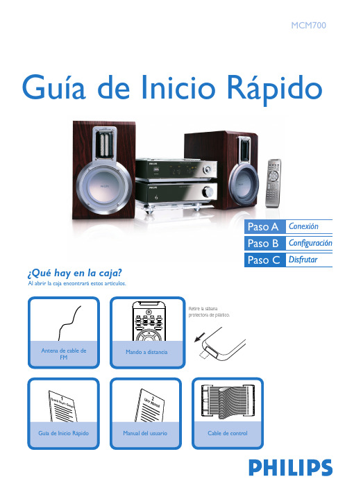
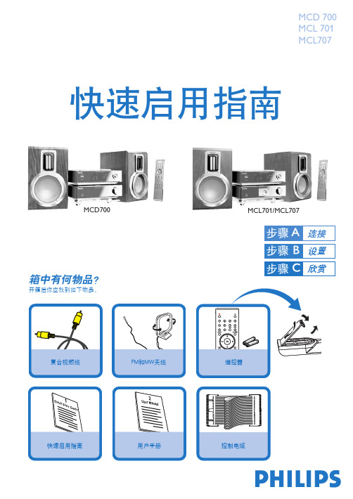
箱中有何物品?
开箱后你应找到如下物品。
使用两条扬声器连接导线将扬声器连接至SPEAKERS(8ohm) 端子。
右边扬声器接至"R" 端子,左边扬声器接到 "L"端子。
将红色导线接至 "+" 极,银白色导线接到 "–" 极。
将随机所附的MW环形天线和FM天线连接至各自所属的端子。
调节天线的位置以获得最佳接收。
使用随机所附的控制电缆将DVD播放机背面标识有CONTROL CABLE字样的串行接口连接至功率扩大机背面的相同接口。
使用随机所附的视频接线(黄色)将DVD播放机背面的VIDEO OUTPUT插口连接至电视机的视频输入插孔。
将DVD播放机的电源线连接至交流电源输出插座。
1
2
3
提示
– 其他的电视连接选项请参阅用户手册。
– 为了连接到一台逐行扫描电视机,请参阅用户手册进行正
确连线和详细设定。
4
5。
- 1、下载文档前请自行甄别文档内容的完整性,平台不提供额外的编辑、内容补充、找答案等附加服务。
- 2、"仅部分预览"的文档,不可在线预览部分如存在完整性等问题,可反馈申请退款(可完整预览的文档不适用该条件!)。
- 3、如文档侵犯您的权益,请联系客服反馈,我们会尽快为您处理(人工客服工作时间:9:00-18:30)。
MC700系列智能多媒体控制系统Intelligent Multimedia Control System(适用于MC700系列机型)用户手册User’s Manual**请在安装使用前认真阅读本说明书**尊敬的用户:感谢您选购我们生产的MC700系列多媒体中央控制器。
该产品具有外观设计小巧高档大方;使用简单方便;功能强大;扩展能力极强;可直接外接其他厂家的设备;三个可编程232口最多可同时控制三个不同厂家的投影机或两个不同矩阵;可对各接口重新定义和单独控制;投影机一键切换;投影幕自动升降;开机即是电脑画面等等多种实用功能。
为了您能安全地使用本设备,发挥其最大的功能,强烈建议在安装使用前先仔细阅读本说明书。
若有任何技术问题或对产品的意见和建议,请与本公司技术服务部联系。
联系方法如下:电话:(020)33534881 61281788传真:(020)61281788地址:广州市天河软件园建工路9号4楼邮编:510600E-mail:laitong@http://特别提醒:1. 在使用本系统的时候,严禁在开机时对各个部件进行插拔(特别是通讯口及VGA接口,这可能会人为损坏设备)。
2. 本控制器为智能开关设计,在雷雨天气或长时间不使用时,请关闭电源总闸。
3. 本控制器内有强电模块,严禁带电自行维修。
目录一、使用说明 (5)1. 中控简介 (5)2. 中控组成 (5)二、硬件连接 (7)1. 连线说明 (7)2. 中控内部跳线说明 (10)三、系统设置 (11)1. 系统通讯协议 (12)2. 开机状态设置 (14)3. 开关机流程设置 (15)4. 开关延时设置 (16)5. 投影机设置 (17)6. 红外学习 (19)7. 按键面板设置 (20)8. 其他设置 (23)四、常见故障处理 (24)1. 按控制面板“系统开”无法开机 (25)2. 红外学习不成功或显示成功却不能遥控 (25)3. 有些设备红外遥控不灵 (25)4. 投影机开关切换不灵 (25)5. 关投影机出问题 (26)一、使用说明1. 中控简介智能多媒体控制系统为现代化的会议中心、电化教室及家居提供了最佳的解决方案。
它将多种影音信号的选择输出及其多种设备的操作集中在一个控制面板、遥控器或电脑软件上。
操作者通过直观的控制操作,就可以对诸多影音设备进行遥控,并能完成影音设备间的信号切换,使之在一个或多个演播设备(如投影机、电视机等)中播出。
并对室内环境(如电动屏幕、电动窗帘、灯光等)实行配合控制,将整个操作变得得心应手。
MC700系列控制器专为多媒体课室等许多连接多媒体设备的应用环境设计。
在原有多媒体控制系统的基础上进行重新设计开发,采用全贴片工艺设计生产,可靠性及稳定性更高,MC700型系列功能主要有电视接收(9XXC)、设备防盗功能、IP电话对讲(IP电话型)、视频(支持色差、S端子)转RGB 数字输出(数码型),升级方便,只要插入相应的功能插卡即可;红外遥控自学习、投影幕键智能联动、一键开关机、232码和红外控投影机、投影机延时等功能都具备,是目前功能最齐全的中央控制主机。
2. 中控组成系统有中央控制器主机和按键面板组成;面板有两种:48键普通面板和液晶47键面板。
1.中央控制主机集成4*2路VGA矩阵,集成4*2路视频矩阵,支持色差和S端子输入(数码型);4*1立体声音频矩阵,集成4路(2路独立)自学习红外遥控功能,可遥控4路红外设备和两路扩展开关;3路安防I/O口(MC720/930有6路安防探测口),可接红外探头、讲台门磁、投影机断线、电脑断线、大门门磁等;集成7路电源管理,控制电动幕、投影机、设备;集成电子锁开关和电脑开关功能;集成投影灯开关检测模块、数码调音控制模块等。
本身功率:20W外形尺寸:480L X 200W X 50H(mm)2.按键面板按键面板采用薄膜开关设计,美观、实用、直观,具有使用寿命长(100万次以上),按键灵敏,操作方便。
部分按键指令可以用户定义。
有2路串口接口。
镶嵌尺寸:211L X 152W(mm)3.简单使用说明系统开关,自动打开设备电源和投影机电源,最后按设定的流程开投影机、放下屏幕等(模式6的流程)。
而当使用结束后,按下“系统关”键,就可以轻松下课或散会了。
系统会自动关投影机、收电动屏幕、延时设定时间后关设备电源、延时几分钟后(可设)关投影机电源、最后关闭主机电源。
在工程师把设备连接调试好后,一般用户可按照以下步骤进行操作:1.开系统:按系统开键,把中控打开,系统所有设备通上电;2.开投影机:按投影机开键,打开投影机,此时投影机打开,同时电动幕下降;3.设备选择:要使用设备,在设备选择拦中直接按对应的键;4.关系统:按系统关即可以把投影机关、幕上升。
投影机、系统自动延时断电。
二、硬件连接1. 连线说明主机供电:接220V电源输入,下面有保险管,配有1个备用的保险。
中控电流输出最大不要超过6A;设备供电:输出220V,可以接外接设备;投影机供电:输出220V,接投影机,要幕与投影机联动,投影机必须接这里;电动幕电源:两个220V电输出,中间是零线,从图中看是左上右下,左边接电动幕的上,右边接电动幕的下;扩展开关:有2个开关,可以接220V,K1和K2输出,入接输入,零线都共用;S端子/色差:是数码中控910/930的时候才有用,接色差或者S端子,引脚定义在后面介绍;电位器:用来调节电动幕与投影机联动有问题的时候用,在常见故障中有介绍;VGA输入:有4个VGA口输入,从左到右分别为0、3、2、1口,可以切换到投影VGA口输出;VGA输出:一路接显示器,一个接投影机,显示器的只能输出电脑口的,投影机的可以通过切换输出4个中的任一个,如果是数码中控,则可以输出视频转换后的信号;视频输入:4路视频输入,如果型号带有线电视的,则是3路视频输入,一路电视信号输入,从左到右分别是0、1、2、3口;视频输出:4路输入可以切换一路输出到投影机的视频,如果是带电视可以输出电视视频信号;话筒输入:2路话筒输入,有线话筒的放大小些,无线话筒放大些;音频输入:4路立体声输入,立体声切换左右声道同时切换,不会也不能分开,从左到右是0、1、2、3口;音频输出:立体声输出,4路选1路输出,音量可调;红外控制:4路红外控制口,一个立体声头有2个红外发射灯是2路红外控制,两灯都是发同样的码,另外一个立体声头也是一样;弱电输出:用来接电子锁和供12V电的,左向右为+12V 地锁,电子锁正极接“锁”,负极接“地”,12V是个双向的,可以有12V输出,若开锁电流大于500mA,则要在+12V接入12V电源,否则容易造成中控CPU电变化大而死机,电子锁和输入或作输出12V都是共一个地;注意:最大12V电流输出不能超过1.5A。
COM1口接电脑串口和投影机232口,COM2口是接面板或者扩展模块的,NET/485是用来接网线做网络控制用的,其中也有安防口,只有网络模块才有这些防区的,IP电话是用来接IP电话手柄的插口,安防I/O是用来接电脑开关门磁安防等。
COM1,COM2,NET,IP电话,安防I/O和S端子接口引脚定义如下:图中为孔从中控后面看,可以发现3、4脚离的远,4、5靠的近。
COM1是用来与电脑通讯和控制投影机的,将中控主机与电脑的通讯线圆口一头插入中控的COM1口,注意接口方向(有箭头标志的在上面),另一头九孔接头接在电脑主机的串口,并确定将其插好。
配线是用来接COM1与电脑串口的,配线小引线一般是用来控投影机的,芯接的是COM1的3,屏蔽皮接的是COM1的5,与电脑串口并在一起的。
采用232码控制若投影机波特率大于等于38400则请将中控主机与电脑通讯线的电脑串口一端的一条小引线(黑、灰色)的细线适量延长至投影机控制口,外面一层为地线接投影机的GND,中间的芯为控制线接投影机的RXD。
若波特率小于38400则接中控COM1的4、5脚,4接RXD,5接地(GND)。
控制面板和控制主机用RJ45网线连接,一头接中控机通讯口COM2,另一头接控制面板COM1(COM2、COM3都可)。
投影机控制可选择红外控制,红外控制请将配件中的红外控制线适量延长后,一头接在中控主机的红外控制的投影机口,另一头放在投影机的红外口接收处,粘好,防止掉了,可以将整个红外头用黑胶布粘遮掩以防干扰。
其他的红外控制也一样。
其它接线可参考中控主机后的接口指示安装即可,若有不明可与工程师联系。
2. 中控内部跳线说明中控主板和VGA板有跳线端子,用户可以根据需要进行跳线,具体跳线作用如下:JP61:1和2短接,则安防1区报警,投影机不报警;2和3短接,则安防1区不报警,投影机报警;JP62:1和2短接,则安防2区报警,电脑不报警;2和3短接,报警,电脑报警;XP64:XP64和XP13连接,则电子锁在关机后也能供电;XP65:连接数码板;XP13:XP13和XP64连接;XP24:网络模块和IP电话模块接口,注意网络模块接口如下图右边应对齐,否则把网络模块烧坏(适用于MC720X,MC930X);XP23:开关按键连接线;XP11:1----+12V,2----地(GND),3----负12V;XP31:1,2-----变压器220V输入,3-----220V零线,4----220V火线,5----设备火线,6-----电动幕上火线,7----电动幕下火线,8------零线公用;JP33:1和2短接,则表示开关K1和K2要中控开机后才有电,2和3短接,则表示开关K1和K2中控不用开机就有电;JP31:1和2短接高频头有效,继电器JD38不能用即K1不能用,2和3短接相反;JP32:1和2短接数码板有效,继电器JD39不能用即K2不能用,2和3短接相反。
内部图如下:三、系统设置系统许多功能可设定修改,满足各种场合和各种用户的不同需求。
系统可设定的功能有开机状态、开关机流程、开关延时、投影机控制、面板按键功能等。
这些功能的设置通过电脑软件来完成,需首先安装相应的电脑设置软件,连接控制主机和电脑的通讯电缆,才能进行各种功能设置。
软件光盘下X:\MCtrl\ MCTRL.exe。
X为光盘,打开软件点击设置可以实现下面的设置,设置密码为:lighton1. 系统通讯协议智能多媒体控制系统各模块之间是通过串行口进行通讯的。
波特率为2400、8数据位、无校验位、1位停止位,通信协议采用类Barco的通信协议,即:起始位+源地址+目的地址+指令+数据+校验码+结束位;校验位为:(源地址+目的地址+指令+数据)mod 256。
接收确认格式(所有指令的接收都有确认):源器件地址:自己的地址;目的器件地址:返回发送指令的器件地址;I.接收应答格式(只数据请求指令有应答):源器件地址:自己的地址;目的器件地址:返回请求数据指令的器件地址;操作指令:发送返回操作请求的指令;操作数据:需要的数据;II.发送数据格式:器件地址:\x00:广播地址;\x01:计算机;\x02:控制面板;\x10:红外遥控模块(主机内,八路遥控);\x11:视频切换模块(主机内,八选二);\x12:音频切换模块(主机内,八选二);\x13:VGA切换模块(主机内,二选一或全不选);\x14: 开关模块(主机内,控制0-5路继电器);\x15:调音控制模块(主机内,控制音量、混响深度等);\x16:投影机串口控制模块 (内部外加模块,串口控制投影机);注:广播数据时,接收器件地址为00;操作指令:系统类:\x07: 读版本遥控类:\x10: 从红外输出0发遥控码(缺省为投影);\x11: 从红外输出1发遥控码(缺省为影碟);\x12: 从红外输出2发遥控码(缺省为录像);\x13: 从红外输出3发遥控码(缺省为展示台);切换类:\x30: 视频切换;\x31: 读视频切换状态;(投影、监视)\x32: 音频切换;\x33: 读音频切换状态;(功放、监听)\x34: VGA切换;\x35: 读VGA切换状态;注:在软件中,起始位、源地址、校验位、结束位都在软件里自动加上,不需要用户输入。