机械毕业设计英文外文翻译444手动变速器如何工作
手动变速器的工作原理详述
手动变速器的工作原理详述手动变速器是一种常见的汽车传动装置,它允许驾驶者在行驶过程中手动选择合适的挡位以改变车辆的速度和扭矩输出。
本文将详细介绍手动变速器的工作原理,从齿轮机构、离合器和操作杆三个方面进行阐述。
一、齿轮机构手动变速器的齿轮机构是实现挡位切换和传动功能的核心部件。
它由一系列平行轴的齿轮组成。
不同挡位的选择会使得不同的齿轮组合在一起,实现不同的变速比。
常见的手动变速器包括常用的H型齿轮机构和X型齿轮机构。
H型齿轮机构具有三个轴和四个齿轮,分别代表着一、二、三挡和倒挡。
当驾驶员通过操作杆将换挡叉推动到相应的位置时,离合器断开连接,该挡位所需的齿轮组合将被锁定在传动轴上,从而实现对应的挡位功能。
X型齿轮机构相较于H型齿轮机构增加了一个轴和一个齿轮,因此可以实现更多的挡位选择。
通过操作杆将换挡叉推动到相应的位置,离合器断开连接,特定的齿轮组合将被锁定在传动轴上。
二、离合器离合器是手动变速器与发动机之间的连接器件,它的主要作用是在挂挡和起步时使发动机与变速器分离,从而实现平稳的换挡和起步动作。
离合器通常由驱动盘、驱动轴和压力盘组成。
在起步阶段,当驾驶员踩下离合器踏板时,压力盘与驱动盘分离,使发动机的动力不能传递给变速器,车辆处于空挡状态。
当驾驶员松开离合器踏板时,压力盘和驱动盘通过离合器压盘弹簧的作用重新连接,发动机的动力通过离合器传递到变速器,车辆开始运动。
三、操作杆操作杆是手动变速器的操控装置,它与变速器的换挡叉相连,通过向前或向后推动操作杆来选择不同的挡位。
操作杆的设计通常采用直杆式或者弧形杆式,以便驾驶员能够准确选择不同的挡位。
当操作杆推动到前方时,齿轮机构会切换到高挡位或者变速器空挡状态;当操作杆推动到后方时,齿轮机构会切换到低挡位或者倒挡状态。
通过掌握操作杆的使用方法,驾驶员可以根据道路条件和行驶速度选择合适的挡位,以实现平稳的加速或降速。
结论手动变速器通过齿轮机构、离合器和操作杆的相互配合,实现了驾驶员对汽车的速度调节和扭矩输出的控制。
手动变速器基础外文文献翻译、中英文翻译、外文翻译

中国地质大学长城学院本科毕业设计外文资料翻译系别:工程技术系专业:机械设计制造及其自动化姓名:黄昌照学号:052115322015 年4月7日Manual Transmission BasicsIt's no secret that cars with manual transmissions are usually more fun to drive than their automatic-equipped counterparts. If you have even a passing interest in the act of driving, then chances are you also appreciate a fine-shifting manual gearbox. But how does a manual trans actually work? With our primer on automatics(or slushboxes, as detractors call them) available for your perusal, we thought it would be a good idea to provide a companion overview on manual trannies, too.A brief history lesson shows that manual transmissions preceded automatics by several decades. In fact, up until General Motors offered an automatic in 1938, all cars were of the shift-it-yourself variety. While it's logical for many types of today's vehicles to be equipped with an automatic -- such as a full-size sedan, SUV or pickup -- the fact remains that nothing is more of a thrill to drive than a tautly suspended sport sedan, sport coupe or two-seater equipped with a precise-shifting five- or six-speed gearbox. It's what makes cars such as a Corvette, Mustang, Miata or any BMW sedan or coupe some of the most fun-to-drive cars available today.We know which types of cars have manual trannies. Now let's take a look at how they work. From the most basic four-speed manual in a car from the '60s to the most high-tech six-speed in a car of today, the principles of a manual gearbox are the same. The driver must shift from gear to gear. Normally, a manual transmission bolts to a clutch housing (or bell housing) that, in turn, bolts to the back of the engine. If the vehicle has front-wheel drive, the transmission still attaches to the engine in a similar fashion but is usually referred to as a transaxle. This is because the transmission, differential and drive axles are one complete unit. In a front-wheel-drive car, the transmission also serves as part of the front axle for the front wheels. In the remaining text, a transmission and transaxle will both be referred to using the term transmission.The function of any transmission is transferring engine power to the driveshaft and rear wheels (or axle halfshafts and front wheels in a front-wheel-drive vehicle). Gears inside thetransmission change the vehicle's drive-wheel speed and torque in relation to engine speed and torque. Lower (numerically higher) gear ratios serve as torque multipliers and help the engine to develop enough power to accelerate from a standstill.Initially, power and torque from the engine comes into the front of the transmission and rotates the main drive gear (or input shaft), which meshes with the cluster or counter shaft gear -- a series of gears forged into one piece that resembles a cluster of gears. The cluster-gear assembly rotates any time the clutch is engaged to a running engine, whether or not the transmission is in gear or in neutral.There are two basic types of manual transmissions. The sliding-gear type and the constant-mesh design. With the basic -- and now obsolete -- sliding-gear type, nothing is turning inside the transmission case except the main drive gear and cluster gear when the trans is in neutral. In order to mesh the gears and apply engine power to move the vehicle, the driver presses the clutch pedal and moves the shifter handle, which in turn moves the shift linkage and forks to slide a gear along the mainshaft, which is mounted directly above the cluster. Once the gears are meshed, the clutch pedal is released and the engine's power is sent to the drive wheels. There can be several gears on the mainshaft of different diameters and tooth counts, and the transmission shift linkage is designed so the driver has to unmesh one gear before being able to mesh another. With these older transmissions, gear clash is a problem because the gears are all rotating at different speeds.All modern transmissions are of the constant-mesh type, which still uses a similar gear arrangement as the sliding-gear type. However, all the mainshaft gears are in constant mesh with the cluster gears. This is possible because the gears on the mainshaft are not splined to the shaft, but are free to rotate on it. With a constant-mesh gearbox, the main drive gear, cluster gear and all the mainshaft gears are always turning, even when the transmission is in neutral.Alongside each gear on the mainshaft is a dog clutch, with a hub that's positively splined to the shaft and an outer ring that can slide over against each gear. Both the mainshaft gear and the ring of the dog clutch have a row of teeth. Moving the shift linkage moves the dog clutch against the adjacent mainshaft gear, causing the teeth to interlock and solidly lock the gear to the mainshaft.To prevent gears from grinding or clashing during engagement, a constant-mesh, fully "synchronized" manual transmission is equipped with synchronizers. A synchronizer typically consists of an inner-splined hub, an outer sleeve, shifter plates, lock rings (or springs) and blocking rings. The hub is splined onto the mainshaft between a pair of main drive gears. Held in place by the lock rings, the shifter plates position the sleeve over the hub while also holding the floating blocking rings in proper alignment.That's the basics on the inner workings of a manual transmission. As for advances, they have been extensive over the years, mainly in the area of additional gears. Back in the '60s, four-speeds were common in American and European performance cars. Most of these transmissions had 1:1 final-drive ratios with no overdrives. Today, overdriven five-speeds are standard on practically all passenger cars available with a manual gearbox.Overdrive is an arrangement of gearing that provides more revolutions of the driven shaft (the driveshaft going to the wheels) than the driving shaft (crankshaft of the engine). For example, a transmission with a fourth-gear ratio of 1:1 and a fifth-gear ratio of 0.70:1 will reduce engine rpm by 30 percent, while the vehicle maintains the same road speed. Thus, fuel efficiency will improve and engine wear will be notably reduced. Today, six-speed transmissions are becoming more and more common. One of the first cars sold in America with a six-speed was the '89 Corvette. Designed by Chevrolet and Zahnradfabrik Friedrichshafen (ZF) and built by ZF in Germany, this tough-as-nails six-speed was available in the Corvette up to the conclusion of the '96 model year. Today, the Corvette uses a Tremec T56 six-speed mounted at the back of the car.Many cars are available today with six-speeds, including the Mazda Miata, Porsche Boxster S and 911, Dodge Viper, Mercedes-Benz SLK350, Honda S2000, BMW 3-Series and many others. Some of these gearboxes provide radical 50-percent (0.50:1) sixth-gear overdrives such as in the Viper and Corvette, while others provide tightly spaced gear ratios like in the S2000 and Miata for spirited backroad performance driving. While the bigger cars mentioned above such as the Viper and Vette often have two overdrive ratios (fifth and sixth) the smaller cars like the Celica and S2000 usually have one overdriven gear ratio (sixth) and fifth is 1:1.Clearly a slick-shifting manual transmission is one of the main components in a fun-to-drive car, along with a powerful engine, confidence-inspiring suspension andcompetent brakes. For more information on a manual transmission's primary partner component, check out our basic primer on clutches and clutch operation.附录B 文献翻译手动变速器基础汽车手动变速器相比于自动变速器的驾驶装备来说,在驾驶方面拥有更多的乐趣,这已不再是什么秘密了。
外文翻译:手动变速器概述

Manual transmissionManual transmission is the most basic of transmission of a type, its effect is changing, and provide the transmission reverse and neutral. Usually, the pilot on the clutch pedal through manipulation and in any HuanDangGan can choose between gear. There are a few manual transmission, such as motorcycles, cars, some transmission shift transmission allows only sequence, the transmission is called sequence shift transmission. In recent years, along with the electronic control components durability, computerized automatic switching clutch automatic shift of transmission in Europe since the start line are more and more popular, car V olkswagen and ford are sold in the city on the double clutch provide updated generation, transmission from the start with two clutches, every shift automatically switch to another group of clutch engagement, need not as quick as traditional in manual have only one group separated again clutch engagement, shifting speed is faster, more small change gear vibration.Internal structure: shaftDecorate a form of transmission shaft type usually have two and three shaft type two kinds. Usually a rear wheel drive car will adopt three axis type, i.e. input shaft transmission, the output shaft and oart. Input shaft front associated with engine, borrow clutch output shaft back-end through the flange and universal transmission device connected.Input shaft and the output shaft in the same horizontal line, with their oart parallel arrangement. From the input shaft power through the gears to preach to the output shaft oart again. In many input and output shaft transmission shaft could engage in together, so to power, then the gear oart called directly. Direct files through uniaxial transmission, the ratio of 1:1, the highest transmission efficiency. Even in the transmission directly, cannot offer the input shaft, and the output shaft is decorated in a straight line to reduce work needed to inherit the torque transmission.Reversing deviceGenerally speaking, the reverse gear reducer than can alsosynchronizerIn synchronized meshing gears have type synchronizer Settings, can make two gear engagement in the first, before the speed reached synchronizer in all of this manual geartransmission of the car has been usedClutch,The clutch is can make two gear with a separate with mechanical parts, two gear transmission power can be combined, but when to speed, so will depend on the first two gear clutch, change gear ratio, the two gear transmission power, continue again Control:GearIn simple terms, the high speed, low speed ShengDang when the time cameEvery car high speedCompared with automatic transmissionThis refers to the automatic transmission of traditional hydraulic transmission, namely through hydraulic torque converter and planetary gear transmission power automatic transmission.Advantages:transmission efficiency than automatic gearboxes for high, of course, theoretically can compare economical.maintenance will be cheaper than transmission.If you want to higher cost, can begin from both the row of convenience and high power手动变速器手动变速器是汽车变速器中最基本的一种类型,其作用是改变传动比,并提供倒档和空档。
车辆工程专业外文翻译自动变速器如何工作
How Automatic Transmissions WorkIf you have ever driven a car with an automatic transmission, then you know that there are two big differences between an automatic transmission and a manual transmission:There is no clutch pedal in an automatic transmission car.There is no gear shift in an automatic transmission car. Once you put the transmission into drive, everything else is automatic.Both the automatic transmission (plus its torque converter) and a manual transmission (with its clutch) accomplish exactly the same thing, but they do it in totally different ways. It turns out that the way an automatic transmission does it is absolutely amazing!In this article, we'll work our way through an automatic transmission. We'll start with the key to the whole system: planetary gear sets. Then we'll see how the transmission is put together, learn how the controls work and discuss some of the intricacies involved in controlling a transmission.Some BasicsJust like that of a manual transmission, the automatic transmission's primary job is to allow the engine to operate in its narrow range of speeds while providing a wide range of output speeds.Without a transmission, cars would be limited to one gear ratio, and that ratio would have to be selected to allow the car to travel at the desired top speed. If you wanted a top speed of 80 mph, then the gear ratio would be similar to third gear in most manual transmission cars.You've probably never tried driving a manual transmission car using only third gear. If you did, you'd quickly find out that you had almost no acceleration when starting out, and at high speeds, the engine would be screaming along near the red-line. A car like this would wear out very quickly and would be nearly undrive able.So the transmission uses gears to make more effective use of the engine's torque, and to keep the engine operating at an appropriate speed.The key difference between a manual and an automatic transmission is that the manual transmission locks and unlocks different sets of gears to the output shaft to achieve the various gear ratios, while in an automatic transmission, the same set of gears produces all of the different gear ratios. The planetary gear set is the device that makes this possible in an automatic transmission.GearsThis automatic transmission uses a set of gears, called a compound planetary gear set, that looks like a single planetary gear set but actually behaves like twoplanetary gear sets combined. It has one ring gear that is always the output of the transmission, but it has two sun gears and two sets of planets.Let's look at some of the parts:First GearIn first gear, the smaller sun gear is driven clockwise by the turbine in the torque converter. The planet carrier tries to spin counterclockwise, but is heldstill by the one-way clutch (which only allows rotation in the clockwise direction) and the ring gear turns the output. The small gear has 30 teeth and the ring gear has 72, so the gear ratio is:Ratio = -R/S = - 72/30 = -2.4:1So the rotation is negative 2.4:1, which means that the output direction would be opposite the input direction. But the output direction is really the same as the input direction -- this is where the trick with the two sets of planets comes in. The first set of planets engages the second set, and the second set turns the ring gear; this combination reverses the direction. You can see that this would also cause the bigger sun gear to spin; but because that clutch is released, the bigger sun gear is free to spin in the opposite direction of the turbineSecond GearThis transmission does something really neat in order to get the ratio needed for second gear. It acts like two planetary gear sets connected to each other with a common planet carrier.The first stage of the planet carrier actually uses the larger sun gear as the ring gear. So the first stage consists of the sun (the smaller sun gear), the planet carrier, and the ring (the larger sun gear).The input is the small sun gear; the ring gear (large sun gear) is held stationary by the band, and the output is the planet carrier. so the formula is:1 + R/S = 1 + 36/30 = 2.2:1The planet carrier turns 2.2 times for each rotation of the small sun gear. At the second stage, the planet carrier acts as the input for the second planetary gear set, the larger sun gear (which is held stationary) acts as the sun, and the ring gear acts as the output, so the gear ratio is:1 / (1 + S/R) = 1 / (1 + 36/72) = 0.67:1To get the overall reduction for second gear, we multiply the first stage by the second, 2.2 x 0.67, to get a 1.47:1 reduction. This may sound wacky, but it works.Third GearMost automatic transmissions have a 1:1 ratio in third gear. You'll remember from the previous section that all we have to do to get a 1:1 output is lock together any two of the three parts of the planetary gear. With the arrangement in this gear set it is even easier -- all we have to do is engage the clutches that lock each of the sun gears to the turbine.If both sun gears turn in the same direction, the planet gears lockup becausethey can only spin in opposite directions. This locks the ring gear to the planets and causes everything to spin as a unit, producing a 1:1 ratio. OverdriveBy definition, an overdrive has a faster output speed than input speed. It's a speed increase. In this transmission, engaging the overdrive accomplishes two things at once. If you read How Torque Converters Work, you learned about lockup torque converters. In order to improve efficiency, some cars have a mechanism that locks up the torque converter so that the output of the engine goes straight to the transmission.In this transmission, when overdrive is engaged, a shaft that is attached to the housing of the torque converter (which is bolted to the flywheel of the engine) is connected by clutch to the planet carrier. The small sun gear freewheels, and the larger sun gear is held by the overdrive band. Nothing is connected to the turbine; the only input comes from the converter housing. Let's go back to our chart again, this time with the planet carrier for input, the sun gear fixed and the ring gear for output.Ratio = 1 / (1 + S/R) = 1 / ( 1 + 36/72) = 0.67:1So the output spins once for every two-thirds of a rotation of the engine. If the engine is turning at 2000 rotations per minute (RPM), the output speed is 3000 RPM. This allows cars to drive at freeway speed while the engine speed stays nice and slow.ReverseReverse is very similar to first gear, except that instead of the small sun gear being driven by the torque converter turbine, the bigger sun gear is driven, and the small one freewheels in the opposite direction. The planet carrier is held by the reverse band to the housing. So, according to our equations from the last page, we have:Ratio = -R/S = 72/36 = 2.0:1So the ratio in reverse is a little less than first gear in this transmission. Gear RatiosThis transmission has four forward gears and one reverse gear. Let's summarize the gear ratios, inputs and outputs:Hydraulic SystemThe automatic transmission in your car has to do numerous tasks. You may not realize how many different ways it operates. For instance, here are some of the features of an automatic transmission:∙If the car is in overdrive (on a four-speed transmission), the transmission will automatically select the gear based on vehicle speed and throttlepedal position.∙If you accelerate gently, shifts will occur at lower speeds than if you accelerate at full throttle.∙If you floor the gas pedal, the transmission will downshift to the next lower gear.∙If you move the shift selector to a lower gear, the transmission will downshift unless the car is going too fast for that gear. If the car is goingtoo fast, it will wait until the car slows down and then downshift.∙If you put the transmission in second gear, it will never downshift or up shift out of second, even from a complete stop, unless you move the shiftlever.∙You've probably seen something that looks like this before. It is really the brain of the automatic transmission, managing all of these functionsand more. The passageways you can see route fluid to all the differentcomponents in the transmission. Passageways molded into the metal arean efficient way to route fluid; without them, many hoses would be needed to connect the various parts of the transmission. First, we'll discuss thekey components of the hydraulic system; then we'll see how they worktogether.The PumpAutomatic transmissions have a neat pump, called a gear pump. The pump is usually located in the cover of the transmission. It draws fluid from a sump in the bottom of the transmission and feeds it to the hydraulic system. It also feeds the transmission cooler and the torque converter.The inner gear of the pump hooks up to the housing of the torque converter, so it spins at the same speed as the engine. The outer gear is turned by the inner gear, and as the gears rotate, fluid is drawn up from the sump on one side of the crescent and forced out into the hydraulic system on the other side.The GovernorThe governor is a clever valve that tells the transmission how fast the car is going. It is connected to the output, so the faster the car moves, the faster the governor spins. Inside the governor is a spring-loaded valve that opens in proportion to how fast the governor is spinning -- the faster the governor spins, the more the valve opens. Fluid from the pump is fed to the governor through the output shaft.The faster the car goes, the more the governor valve opens and the higher the pressure of the fluid it lets through.Valves and ModulatorsThrottle Valve or ModulatorTo shift properly, the automatic transmission has to know how hard the engine is working. There are two different ways that this is done. Some cars have a simple cable linkage connected to a throttle valve in the transmission. The further the gas pedal is pressed, the more pressure is put on the throttle valve. Other cars use a vacuum modulator to apply pressure to the throttle valve. The modulator senses the manifold pressure, which drops when the engine is under a greater load.Manual ValveThe manual valve is what the shift lever hooks up to. Depending on which gear is selected, the manual valve feeds hydraulic circuits that inhibit certain gears. For instance, if the shift lever is in third gear, it feeds a circuit that prevents overdrive from engaging.Shift ValvesShift valves supply hydraulic pressure to the clutches and bands to engage each gear. The valve body of the transmission contains several shift valves. The shift valve determines when to shift from one gear to the next. For instance, the 1 to 2 shift valve determines when to shift from first to second gear. The shift valve is pressurized with fluid from the governor on one side, and the throttle valve on the other. They are supplied with fluid by the pump, and they route that fluid to one of two circuits to control which gear the car runs in.The shift valve will delay a shift if the car is accelerating quickly. If the car accelerates gently, the shift will occur at a lower speed. Let's discuss what happens when the car accelerates gently.As car speed increases, the pressure from the governor builds. This forces the shift valve over until the first gear circuit is closed, and the second gear circuit opens. Since the car is accelerating at light throttle, the throttle valve does not apply much pressure against the shift valve.When the car accelerates quickly, the throttle valve applies more pressure against the shift valve. This means that the pressure from the governor has to be higher (and therefore the vehicle speed has to be faster) before the shift valve moves over far enough to engage second gear.Each shift valve responds to a particular pressure range; so when the car is going faster, the 2-to-3 shift valve will take over, because the pressure from the governor is high enough to trigger that valve.Electronic ControlsElectronically controlled transmissions, which appear on some newer cars, still use hydraulics to actuate the clutches and bands, but each hydraulic circuit is controlled by an electric solenoid. This simplifies the plumbing on the transmission and allows for more advanced control schemes.自动变速器如何工作如果你曾经驾驶过一辆带着自动变速器的车, 那么你就知道自动变速器和手动变速器之间有很大的不同:在一个带着自动变速器的汽车中没有离合器踏板。
24 机械工程英语 学生工作页:手动变速器的工作

总结知识点
评
价
类别
比例
成绩
签名
成果评定
根据学习成果评定成绩,占 60%
学生自评
学生根据对执行任务过程进行自评,给出相应的成绩,占10%
学生互评
学生间根据课堂口语表达及表现,互相评价,占10%
教师评价
教师根据对学生的学习态度、出勤率、课堂表现、沟通与表达能力,并结合执行任务过程的各个环节进行评价,占20%
任务2:Two types of transmission are the manual and the automatic .
任务3:The gear shift mechanism consists of a lever, shift forks shaft, shift forks, locks and a reverse speed safety device.
合计
3)具备表达能力、团结协作能力、计划组织能力等职业素养。
接受任务班组
班 组
姓名
接受任务时间
资讯学习及任务执行
Ⅰ.The work of manual transmission(Textexplanation)
资讯1:device[dɪˈvaɪs]n.装置,设备
任务1:A transmission is a speed and power changing device installed at some point between the engine and driving wheels of the vehicle. Two types of transmission are the manual and the automatic.
外文翻译-手动变速器

附录附录A.Manual TransmissionIt’s no secret that cars with manual transmissions are usually more fun to drive than the automatic-equipped counterparts. If you have even a passing interest in the act of driving, then chances are you also appreciate a fine-shifting manual gearbox. But how does a manual transmission actually work?A history hows that manual transmissions preceded automatics by several decades. In fact,up until General Motors offered an automatic in 1938, all cars were of the shift-it-yourself variety. While it’s logical for many types of today’s vehicles to be equipped with an automatic――such as a full-size sedan, SUV or pickup――the fact remains that nothing is more of a thrill to drive than a tautly suspended sport sedan, snort coupe or two-sealer equipped with a precise-shifting five-or six-speed gearbox.We know whicn types or cars have manual trannies. Now let’s take a loo k at how they work. From the most basic four-speed manual in a car from the’60s to the most high-tech six-speed one in a car of today, the principles of a manual gearbox are the same. The driver must shift from gear to gear. Normally, a manual transmission bolts to a clutch housing (or bell housing), in turn, bolts to the back of the engine. If the vehicle has front-wheel drive, the transmission still attaches to the engine in a similar fashion but is usually referred to as a transaxle. This is because the transmission, differential and drive axles are one complete unit. In a front-wheel-drive car, the transmission also serves as part of the front axle for the front wheels. In the remaining text, a transmission and a transaxle will both be referred to using the term transmission.The function of any transmission is transferring engine power to the driveshaft and rear wheels (or axle halfshafts and front wheels in a front-wheel-drive vehicle). Gears inside the transmission change the vehicle’s drive-wheel speed and torque in relation to engine speed and torque.Lower(numerically higher) gear ratios serve as torque multipliers and help the engine to develop enough power to accelerate from a standstill.Initially, power and torque from the engine comes into the front of the transmissions and rotates the main drive gear (or input shaft), which meshes with the cluster or countersha ft gear――a series of gears forged into one piece that resembles a cluster of gears. The cluster-gear assembly rotates any time the clutch is engaged to a running engine,whether or not the transmission is in gear or in neutral.There are two basic types of manual transmissions. The sliding-gear type and the constant-mesh design. With the basic――and now obsolete――sliding-gear type,nothing is turning inside the transmission case except the main drive gear and cluster gear when the trans is in neutral. In order to mesh the gears and apply engine power to move the vehicle, the driver presses the clutch pedal and moves the shifter handle, which in turn moves the shift linkage and forks to slide a gear along the mainshaft, which is mounted directly above the clust er. Once the gears are meshed, the clutch pedal is released and the engine’s power is sent to the drive wheels. There can be several gears on the mainshaft of different diameters and tooth counts, and the transmission shift linkage is designed so the driver has to unmesh one gear before being able to mesh another. With these older transmissions, gear clash is a problem because the gears are all rotating at different speeds.All modern transmissions are of the constant-mesh type, which still uses a similar gear arrangement as the sliding-gear type. However,all the mainshaft gears are in constant mesh with the cluster gears. This is possible because the gears on the mainshaft are not splined to the shaft, but are free to rotate on it. With a constant-mesh gearbox, the main drive gear, cluster gear and all the mainshaft gears are always turning, even when the transmission is in neutral.Alongside each gear on the mainshaft is a dog clutch, with a hub that’s positively splined to the shaft and an outer ring that can slide over against each gear. Both the mainshaft gear and the ring of the dog clutch have a row of teeth. Moving shift linkage moves the dog clutch against the adjacent mainshaft gear, causing the teeth to interlock and solidly lock the gear to the mainshaft.To prevent gears from grinding or clashing during engagement, a constant-mesh, fully "synchronized" manual transmission is equipped with synchronizers. A synchronizer typically consists of an inner-splined hub, an outer sleeve, shifter plates,lock rings(or springs)and blocking rings. The hub is splined onto the mainshaft between a pair of main drive gears. Held in place by the lock rings,the shifter plates position the sleeve over the hub while also holding the floating blocking rings in proper alignment.A synchro’s inner hub and sleeve are made of steel, but the blocking ring――the partof the synchro that rubs on the gear to change its speed――is usually made of a softer material, such as brass. The blocking ring has teeth that match the teeth on the dog clutch. Most synchros perform double duty――they push the synchro in one direction and lock one gear to the mainshaft. Push the synchro the other way and it disengages from the first gear, passes through a neutral position, and engages a gear on the other side.That’s the basics on the inner workings of a manual transmission. As for advances, they have been extensive over the years, mainly in the area of additional gears. Back in the 60’s, four-speeds were common in American and European performance cars.Most of these transmissions had 1:1 final-drive ratios with no overdrives. Today, overdriven five-speeds are standard on practically all passenger cars available with a manual gearbox.Overdrive is an arrangement of gearing that provides more revolutions of the driven shaft(the driveshaft going to the wheels)than the driving shaft(crankshaft of the engine). For example, a transmission with a fourth-gear ratio of 1:1 and a fifth-gear ratio of 0.70:1 will reduce engine rpm by 30 percent, while the vehicle maintains the same road speed. Thus, fuel efficiency will improve and engine wear will be notably reduced. Today, six-speed transmissions are becoming more and more common. One of the first cars sold in America with a six-speed was the ’89 Corvette. D esigned by Chevrolet and Zahnradfabrik Friedrichshafen(ZF)and built by ZF in Germany, this tough-as-nails six-speed was available in the Corvette up to the conclusion of the ’96 model year. Today,the Corvette uses a Tremec T56 six-speed mounted at the back of the car.Many cars are available today with six-speeds, including the Mazda Miata, Porsche Boxster S and 911, Dodge Viper, Mercedes-Benz SLK320, Honda S2000, Toyota Celica GT-S and many others. Some of these gearboxes provide radical 50-percent (0.50:1) sixth-gear overdrives such as in the Viper and Corvette, while others provide tightly spaced gear ratios like in the S2000 and Celica for spirited backroad performance driving. While the bigger cars mentioned above such as the Viper and Vette often have two overdrive ratios(fifth and sixth)the smaller cars like the Celica and S2000 usually have one overdriven gear ratio(sixth) and fifth is 1:1.Clearly a slick-shifting manual transmission is one of the main components in a fun-to-drive car, along with a powerful engine,confidence-inspiring suspension and competent brakes.附录B.手动变速器相对于自动变速箱的车手动变速箱汽车开起来有更好的驾驶乐趣这是众所周知的。
手动变速器工作原理

手动变速器工作原理手动变速器是一种用于汽车和其他机械设备上的传动装置,它允许驾驶员通过改变齿轮的比例来更改车辆的速度和扭矩输出。
手动变速器主要由离合器、齿轮、齿轮轴和选择机构组成。
在这篇文章中,我们将详细介绍手动变速器的工作原理。
手动变速器有多个齿轮,每个齿轮的大小和齿数都不相同。
这些齿轮通过齿轮轴彼此相连。
当驾驶员操作变速杆时,选择机构将根据驾驶员的选择移动齿轮,从而改变齿轮之间的连接方式。
这种改变会导致不同的齿轮比例,进而影响车辆的输出扭矩和速度。
变速器的工作原理可以从离合器开始介绍。
离合器是连接发动机和变速器的装置,它允许驾驶员在不停止发动机的情况下换挡。
离合器由离合器盘、压盘和离合器轴承组成。
当驾驶员踩下离合器踏板时,压盘与离合器盘之间的压力消除,离合器盘与发动机之间断开连接,发动机的转动不会传递到变速器。
当驾驶员松开离合器踏板时,压盘与离合器盘之间的压力增加,离合器盘与发动机重新连接起来,发动机的转动就会传递到变速器。
对于手动变速器,不同的齿轮组合会产生不同的变速比。
变速比是指发动机转动一圈,车轮转动的圈数。
较高的变速比意味着发动机转动更多圈才能使车轮转动一圈,这会产生更大的扭矩输出,但速度会相应降低。
相反,较低的变速比意味着发动机转动较少圈数使车轮转动一圈,这会产生更高的速度,但扭矩可能会减小。
在手动变速器中,常见的齿轮组合包括一、二、三、四挡和倒挡。
一挡通常被用于起步,它使用最小的齿轮比例,提供最大的扭矩输出,但速度相对较低。
二、三和四挡则用于不同的行驶速度范围,随着挡位的增加,齿轮比例逐渐增大,扭矩输出相应减小,速度逐渐增加。
倒挡用于倒车时,将齿轮反向旋转,让车辆向后移动。
在驾驶过程中,驾驶员通过变速杆选择不同的挡位。
变速杆控制选择机构,选择机构则将变速杆的动作传递给相应的齿轮。
选择机构通常由一组齿轮和滑块组成。
当驾驶员移动变速杆时,滑块会滑动到相应的齿轮上,使其与其他齿轮相连或断开。
汽车变速器的设计外文文献翻译、中英文翻译、外文翻译

本科毕业设计(论文)英文资料翻译*****指导教师:孙飞豹(副教授)学科、专业:车辆工程沈阳理工大学应用技术学院2011年12月20日transmission used in automobilesA standard transmission or manual transmission is the traditional type of transmission used in automobiles. The manual or standard transmission consists of a series of gears, synchros, roller bearings, shafts and gear selectors. The main clutch assembly is used to engage and disengage the engine from the transmission. Heliacal cut gears are used to select the ratio desired the sector fork move gears from one to another by using the gearshift knob. Synchros are used to slow the gear to a stop before it is engaged to avoid gear grinding, the counter shaft hold the gears in place and against the main input and output shaft. A stick shift transmission has no torque converter so there is no need for a transmission cooler. A stick shift transmission needs a simple fluid change for proper service. (there is no transmission filter in a stick shift transmission).Transmission ShifterMost manual transmissions have one reverse gear and four to six forward gears. Some cars also have eight forward gears while thirteen to twenty-four gears are present in semi trucks. To differentiate among the available standard transmissions, they are addressed by the number of forward gears. For example, if the standard transmission has five gears, it will be referred to as 5-speed standard transmission or 5-speed standard.Typical Standard Transmission ConfigurationInside the transmission shafts contain all forward and reverse gears. Most transmissions contain three shafts: input shaft, output shaft and counter or lay shaft. Other than standard transmission, there are other transmissions like continuously variable transmission, automatic transmission and semi-automatic transmission. In the manual transmission, a pair of gears inside the transmission selects the gear ratios. Whereas, in an automatic transmission, combination of brake bands and clutch packs control the planetary gear which selects the gear ratio.If there is a provision to select a gear ratio manually in automatic transmissions, the system is called a semi-automatic transmission. The driver can select from any of the gears at any pointof time. In some automobiles like racing cars and motorcycles that have standard transmissions, the driver can select the preceding or the following gear ratio with no clutch operation needed. This type of standard transmission is known as sequential transmission. In this transmission the clutch is still used for initial take off.Clutch and Flywheel AssemblyThe main clutch plays the role of a coupling device which separates the transmission and the engine. If the clutch is absent and the car comes to a stop the engine will stall. In automobiles, the clutch can be operated with the help of a pedal located on the floor of the vehicle. In an automatic transmission instead of a clutch, a torque converter is used to separate the transmission and engine.Typical Stick Shift PatternsA desired gear can be selected by a lever which is usually located on the floor in between the driver and passenger seat. This selector lever is called the gear lever or gear selector or gear shift or shifter. This gear stick can be made to move in right, left, forward and backward direction. When the gear is placed on the N position or neutral position, no gear will be selected. To move the car in the backward direction, the R gear or reverse gear should be selected.Standard transmissions are more efficient and less expensive to produce than automatic transmissions. A Standard transmission is about 15% more efficient compared to an automatic transmission. Standard transmissions are generally stronger than automatic transmissions and off road vehicles take advantage of a direct gear selection so they can withstand rough conditions. Less active cooling is also required in manual transmission system because less power is wasted.●Popular Problem ChecksCar will not go into gearClutch disc is broken completelyInternal transmission damageFailed clutch master cylinderSeized clutch slave cylinderBroken clutch fork pivotBroken clutch cableCar goes into gear but it fades out or is slippingClutch is worn out and needs replacementClutch is oil soaked from a external engine oil leakCar makes grinding noise while operating or shifting gearsOne of the roller or thrust bearings has failedThe gear synchro is worn out not forcing the gear stop before it is engaged causing a grinding gear.A counter or main shaft bearing has failed causing misalignment of the gears●Troubleshooting Noise and ProblemsIf the vehicle is running and a whirring sound is heard, then it goes away when the clutch is depressed, the transmission input bearing has failed.If the transmission is quiet in neutral but when you depress the clutch a squeaking noise is observed, a clutch throw out bearing has failed.Tips:Never let little noises go unattended; a small noise can cause a large noise and transmission operation failure. Never overload a vehicle or tow beyond the capacity this can cause premature transmission failure.汽车变速器汽车传统变速器是那种标准的手动变速器。
手动变速器工作原理

手动变速器工作原理
手动变速器是机动车辆中常用的变速器,是将发动机的输出转矩和车轮的实际行驶速度进行转换的装置,它的作用是使发动机的输出转矩适应变化的车轮的行驶速度,从而使车辆能够顺利行驶。
手动变速器有几个主要组成部分,例如变速箱、动力轴、变速器、齿轮和桥。
其中,动力轴连接发动机和变速箱,变速器安装在变速箱中,由多个齿轮组成,桥是连接变速器和车轮的重要元件。
变速箱负责将发动机轴上的动力传递给变速器,同时保持变速器及其内部零部件在一定的润滑状态。
变速器由一系列的内外齿轮组成,它是主要的变速元件。
内齿轮与外齿轮的尺寸和啮合方式决定了桥和车轮之间的传动比,以及转矩的输出。
桥由一系列齿轮配合而成,桥和主轴之间的连接方式决定车轮所能实际行驶的最低速度和最高速度。
手动变速器的具体工作原理如下:连接变速器和发动机的动力轴上的转矩先通过变速箱和变速器的内部齿轮传输给变速器,然后由变速器的内齿轮和外齿轮进行相应的转矩转换,转换后的转矩再被传递给桥,最后桥的齿轮连接到主轴,将传动比传递给车轮,达到变速的效果。
当发动机给定的输出转矩传输到变速箱和变速器上时,根据操纵者按动换挡拨片,有不同的变速齿轮会带动变速器内齿轮、外齿轮和桥上的其它齿轮发生相应的运动,使变速器内部齿轮之间和车轮之间的传动比发生变化,从而实现车轮的不同速度。
所以,由于变速器的作用,使发动机在维持低速度下的功率能够极大的提高,也就使车辆的行驶平稳安全,并且能在相同的发动机功率下行驶不同的距离,从而提高汽车的能耗效率。
手动变速器的工作原理

手动变速器的工作原理
手动变速器是一种机械装置,用于改变发动机输出转矩的传输比,以适应不同的行驶工况和车速要求。
它由多个齿轮组成,可以手动选择不同的齿轮组合来实现不同的车速。
手动变速器的工作原理如下:
1. 输入轴:输入轴连接到发动机,将发动机的转动力矩传递给变速器。
2. 输出轴:输出轴连接到驱动轮,将变速器输出的动力传递给车轮。
3. 齿轮组:手动变速器由一系列齿轮组成,包括主轴和从动轴。
主轴上有多个齿轮,并与发动机输入轴相连。
从动轴上也有多个齿轮,并与输出轴相连。
4. 操作杆:操作杆用于手动选择相应的齿轮组合。
通过移动操作杆,可以将主轴上的不同齿轮与从动轴上的齿轮相连,从而改变输出的传输比例。
5. 离合器:手动变速器还配备有离合器机构,用于将发动机与变速器分离,以实现换挡和停车。
在使用手动变速器时,驾驶员通过操作离合器和操作杆来选择适当的齿轮组合,从而实现不同的传输比例。
较低的齿轮比能够提供更大的扭矩输出,适用于起步和爬坡等高负荷工况。
而
较高的齿轮比则可以提供更高的车速,适用于平路行驶和高速巡航。
总而言之,手动变速器通过合理选择齿轮组合,使发动机输出的力矩通过不同的齿轮之间的传递和减速,适应不同的行驶条件和车速需求。
外文 介绍自动变速器是如何工作

一.Introduction to How Automatic Transmissions Work If you have ever driven a car with an automatic transmission, then you know that there are two big differences between an automatic transmission and a manual transmission:There is no clutch pedal in an automatic transmission car.There is no gear shift in an automatic transmission car. Once you put the transmission into drive, everything else is automatic.Both the automatic transmission (plus its torque converter) and a manual transmission(with its clutch) accomplish exactly the same thing, but they do it in totally different ways. It turns out that the way an automatic transmission does it is absolutely amazing!Purpose of an Automatic TransmissionJust like that of a manual transmission, the automatic transmission's primary job is to allow the engine to operate in its narrow range of speeds while providing a wide range of output speeds.Without a transmission, cars would be limited to one gear ratio, and that ratio would have to be selected to allow the car to travel at the desired top speed. If you wanted a top speed of 80 mph, then the gear ratio would be similar to third gear in most manual transmission cars.You've probably never tried driving a manual transmission car using only third gear. If you did, you'd quickly find out that you had almost no acceleration when starting out, and at high speeds, the engine would be screaming along near the red-line. A car like this would wear out very quickly and would be nearly undriveable.So the transmission uses gears to make more effective use of the engine's torque, and to keep the engine operating at an appropriate speed. When towing or hauling heavy objects, your vehicle's transmission can get hot enough to burn up the transmission fluid. In order to protect the transmission from serious damage, drivers who tow should buy vehicles equipped with transmission coolers.The key difference between a manual and an automatic transmission is that the manual transmission locks and unlocks different sets of gears to the output shaft to achieve the various gear ratios, while in an automatic transmission, the same set of gears produces all of the different gear ratios. The planetary gearset is the device that makes this possible in an automatic transmissionThe Planetary GearsetFrom left to right: the ring gear, planet carrier, and two sun gearsWhen you take apart and look inside an automatic transmission, you find a huge assortment of parts in a fairly small space. Among other things, you see:An ingenious planetary gearsetA set of bands to lock parts of a gearsetA set of three wet-plate clutches to lock other parts of the gearsetAn incredibly odd hydraulic system that controls the clutches and bandsA large gear pump to move transmission fluid aroundThe center of attention is the planetary gearset. About the size of a cantaloupe, this one part creates all of the different gear ratios that the transmission can produce. Everything else in the transmission is there to help the planetary gearset do its thing.An automatic transmission contains two complete planetary gearsets folded together into one component. See How Gear Ratios Work for an introduction to planetary gearsets.Any planetary gearset has three main components:The sun gearThe planet gears and the planet gears' carrierThe ring gearEach of these three components can be the input, the output or can be held stationary. Choosing which piece plays which role determines the gear ratio for the gearset. Clutches and Bands in an Automatic TransmissionIn this transmission, when overdrive is engaged, a shaft that is attached to the housing of the torque converter (which is bolted to the flywheel of the engine) is connected by clutch to the planet carrier. The small sun gear freewheels, and the larger sun gear is held by the overdrive band. Nothing is connected to the turbine; the only input comes from the converter housing.To get the transmission into overdrive, lots of things have to be connected and disconnected by clutches and bands. The planet carrier gets connected to the torque converter housing by a clutch. The small sun gets disconnected from the turbine by a clutch so that it can freewheel. The big sun gear is held to the housing by a band so that it could not rotate. Each gear shift triggers a series of events like these, withdifferent clutches and bands engaging and disengaging.BandsIn this transmission there are two bands. The bands in a transmission are, literally, steel bands that wrap around sections of the gear train and connect to the housing. They are actuated by hydraulic cylinders inside the case of the transmission.One of the bandsIn the figure above, you can see one of the bands in the housing of the transmission The gear train is removed. The metal rod is connected to the piston, which actuates the band.Above you can see the two pistons that actuate the bands. Hydraulic pressure, routed into the cylinder by a set of valves, causes the pistons to push on the bands, locking that part of the gear train to the housing.The clutches in the transmission are a little more complex. In this transmission there are four clutches. Each clutch is actuated by pressurized hydraulic fluid that enters a piston inside the clutch. Springs make sure that the clutch releases when the pressure is reduced. Below you can see the piston and the clutch drum. Notice the rubber seal on the piston -- this is one of the components that is replaced when your transmission gets rebuilt.The next figure shows the alternating layers of clutch friction material and steel plates.The friction material is splined on the inside, where it locks to one of the gears. The steel plate is splined on the outside, where it locks to the clutch housing. These clutch plates are also replaced when the transmission is rebuilt.The clutch platesThe pressure for the clutches is fed through passageways in the shafts. The hydraulic system controls which clutches and bands are energized at any given moment. Automatic Transmissions: Hydraulics, Pumps and the GovernorHydraulicsThe automatic transmission in your car has to do numerous tasks. You may not realize how many different ways it operates. For instance, here are some of the features of an automatic transmission:. If the car is in overdrive (on a four-speed transmission), the transmission will automatically select the gear based on vehicle speed and throttle pedal position..If you accelerate gently, shifts will occur at lower speeds than if you accelerateat full throttle..If you floor the gas pedal, the transmission will downshift to the next lower gear..If you move the shift selector to a lower gear, the transmission will downshift unless the car is going too fast for that gear. If the car is going too fast, it willwait until the car slows down and then downshift..If you put the transmission in second gear, it will never downshift or upshiftout of second, even from a complete stop, unless you move the shift lever.You've probably seen something that looks like this before. It is really the brain of the automatic transmission, managing all of these functions and more. The passagewaysyou can see route fluid to all the different components in the transmission. Passageways molded into the metal are an efficient way to route fluid; without them, many hoses would be needed to connect the various parts of the transmission. First, we'll discuss the key components of the hydraulic system; then we'll see how they work together.The PumpAutomatic transmissions have a neat pump, called a gear pump. The pump is usually located in the cover of the transmission. It draws fluid from a sump in the bottom of the transmission and feeds it to the hydraulic system. It also feeds the transmission cooler and the torque converter.The inner gear of the pump hooks up to the housing of the torque converter, so it spins at the same speed as the engine. The outer gear is turned by the inner gear, and as the gears rotate, fluid is drawn up from the sump on one side of the crescent and forced out into the hydraulic system on the other side.The GovernorThe governor is a clever valve that tells the transmission how fast the car is going. It is connected to the output, so the faster the car moves, the faster the governor spins. Inside the governor is a spring-loaded valve that opens in proportion to how fast the governor is spinning -- the faster the governor spins, the more the valve opens. Fluid from the pump is fed to the governor through the output shaft.The governorAutomatic Transmissions: Valves and ModulatorsTo shift properly, the automatic transmission has to know how hard the engine is working. There are two different ways that this is done. Some cars have a simple cable linkage connected to a throttle valve in the transmission. The further the gas pedal is pressed, the more pressure is put on the throttle valve. Other cars use a vacuum modulator to apply pressure to the throttle valve. The modulator senses the manifold pressure, which increases when the engine is under a greater load.The manual valve is what the shift lever hooks up to. Depending on which gear isselected, the manual valve feeds hydraulic circuits that inhibit certain gears. For instance, if the shift lever is in third gear, it feeds a circuit that prevents overdrive from engaging.hift valves supply hydraulic pressure to the clutches and bands to engage each gear. The valve body of the transmission contains several shift valves. The shift valve determines when to shift from one gear to the next. For instance, the 1 to 2 shift valve determines when to shift from first to second gear. The shift valve is pressurized with fluid from the governor on one side, and the throttle valve on the other. They are supplied with fluid by the pump, and they route that fluid to one of two circuits to control which gear the car runs in.The shift valve will delay a shift if the car is accelerating quickly. If the car accelerates gently, the shift will occur at a lower speed. Let's discuss what happens when the car accelerates gently.As car speed increases, the pressure from the governor builds. This forces the shift valve over until the first gear circuit is closed, and the second gear circuit opens. Since the car is accelerating at light throttle, the throttle valve does not apply much pressure against the shift valve.When the car accelerates quickly, the throttle valve applies more pressure against the shift valve. This means that the pressure from the governor has to be higher (and therefore the vehicle speed has to be faster) before the shift valve moves over far enough to engage second gear.Each shift valve responds to a particular pressure range; so when the car is going faster, the 2-to-3 shift valve will take over, because the pressure from the governor is high enough to trigger that valve.Electronically Controlled TransmissionsElectronically controlled transmissions, which appear on some newer cars, still use hydraulics to actuate the clutches and bands, but each hydraulic circuit is controlled by an electric solenoid. This simplifies the plumbing on the transmission and allows for more advanced control schemes.Electronically controlled transmissions have even more elaborate control schemes. In addition to monitoring vehicle speed and throttle position, the transmission controller can monitor the engine speed, if the brake pedal is being pressed, and even the anti-lock braking system.Using this information and an advanced control strategy based on fuzzy logic -- a method of programming control systems using human-type reasoning -- electronically controlled transmissions can do things like:Downshift automatically when going downhill to control speed and reduce wear on the brakesUpshift when braking on a slippery surface to reduce the braking torque applied by the engineInhibit the upshift when going into a turn on a winding roadLet's talk about that last feature -- inhibiting the upshift when going into a turn on a winding road. Let's say you're driving on an uphill, winding mountain road. When you are driving on the straight sections of the road, the transmission shifts into secondgear to give you enough acceleration and hill-climbing power. When you come to a curve you slow down, taking your foot off the gas pedal and possibly applying the brake. Most transmissions will upshift to third gear, or even overdrive, when you take your foot off the gas. Then when you accelerate out of the curve, they will downshift again. But if you were driving a manual transmission car, you would probably leave the car in the same gear the whole time. Some automatic transmissions with advanced control systems can detect this situation after you have gone around a couple of the curves, and "learn" not to upshift again.。
手动变速器工作原理

手动变速器工作原理
手动变速器是一种传动装置,用于改变发动机的转速和车轮的转速之间的关系,以在不同的道路和驾驶条件下提供合适的动力和速度。
其工作原理如下:
1. 手动变速器通常由一系列齿轮组成,这些齿轮根据车辆的需求来传递动力和控制转速。
2. 变速器的主要部分是输入轴和输出轴,其中输入轴连接着发动机,输出轴连接着车轮。
发动机的动力通过输入轴传递到齿轮系统中。
3. 变速器通过多个齿轮的组合来改变输出轴的速度和力矩。
不同的齿轮比可以提供不同的速度和转矩输出。
4. 齿轮之间的换挡操作通过离合器的控制来完成。
离合器可以连接或断开发动机和变速器之间的动力传递。
5. 在换挡时,驾驶员通过操作离合器和换挡杆来选择合适的齿轮。
当离合器踏板踩下时,发动机的动力不再传递到齿轮系统中,此时可以进行换挡操作。
6. 一旦换挡杆移动到目标齿轮的位置,驾驶员释放离合器踏板,使其连接发动机和变速器,实现换挡。
此时,发动机的动力重新传递到齿轮系统,输出轴的速度和力矩发生相应的变化。
通过操作离合器和换挡杆,驾驶员可以根据驾驶需求和道路条件选择合适的齿轮比,以实现理想的动力和速度输出。
汽车手动变速箱外文及其部分翻译共30页word资料

MANUAL GEARBOXES9.1 MANUAL GEARBOX CLASSIFICATIONGearboxes are normally classified according to the number of toothed wheelcouples (stages) involved in the transmission of motion at a given speed; in thecase of manual vehicle transmissions, the number to be taken into account isthat of the forward speeds only, without consideration of the final gear, even ifincluded in the gearbox.Therefore there are:• Single stage gearboxes• Dual stage or countershaft gearboxes• Multi stage gearboxesFigure 9.1 shows the three configurations for a four speed gearbox.It is useful to comment on the generally adopted rules of these schemes. Each wheel is represented by a segment whose length is proportional to the pitchdiameter of the gear; the segment is ended by horizontal strokes, representingthe tooth width. If the segment is interrupted where crossing the shaft, thegear wheel is idle; the opposite occurs if the segment crosses the line of theshaft without interruption. Then the wheel rotates with the shaft. Hubs arerepresented according to the same rules, while sleeves are represented with apair of horizontal strokes. Arrows show the input and output shafts. Single stage gearboxes are primarily applied to front wheel driven vehicles,because in these it is useful that the input and the output shaft are offset; inG. Genta and L. Morello, The Automotive Chassis, Volume 1: Components Design, 425Mechanical Engineering Series,c Springer Science+Business Media B.V. 2009426 9. MANUAL GEARBOXES FIGURE 9.1. Schemes for a four speed gearbox shown in three differentconfigurations:a: single stage, b: double stage and c: triple stage.conventional vehicles, on the other hand, it is better that input and output shaftsare aligned.This is why rear wheel driven vehicles usually adopt a double stage gearbox.The multi-stage configuration is sometime adopted on front wheel driven vehicles with transversal engine, because the transversal length of the gearboxcan be shortened; it is used when the number of speeds or the width of the gearsdo not allow a single stage transmission to be used.It should be noted that on a front wheel driven vehicle with transversal engine, having decided on the value of the front track and the size of the tire,the length of the gearbox has a direct impact on the maximum steering angle ofthe wheel and therefore on the minimum turning radius.The positive result on the transversal dimension of multi-stage gearboxes isoffset by higher mechanical losses, due to the increased number of engaged gearwheels.It should be noted that in triple stage gearboxes, shown in the picture, theaxes of the three shafts do not lie in the same plane, as the scheme seems toshow. In a lateral view, the outline of the three shafts should be represented asthe vertices of a triangle; this lay-out reduces the transversal dimension of thegearbox. In this case and others, as we will show later, the drawing is representedby turning the plane of the input shaft and of the counter shaft on the plane ofthe counter shaft and of the output shaft.Gear trains used in reverse speed are classified separately. The inversion ofspeed is achieved by using an additional gear. As a matter of fact, in a train ofthree gears, the output speed has the same direction as the input speed, whilethe other trains of two gears only have an output speed in the opposite direction;the added gear is usually called idler.The main configurations are reported in Fig. 9.2.In scheme a, an added countershaft shows a sliding idler, which can match two close gears that are not in contact, as, for example, the input gear of thefirst speed and the output gear of the second speed. It should be noted that, inthis scheme, the drawing does not preserve the actual dimension of the parts.9.1 Manual gearbox classification 427FIGURE 9.2. Schemes used for reverse speed; such schemes fit every type of gearboxlay-out.Scheme b shows instead two sliding idlers, rotating together; this arrange-ment offers additional freedom in obtaining a given transmission ratio. The coun-tershaft is offset from the drawing plane; arrows show the gear wheels that matchwhen the reverse speed is engaged.Scheme c is similar to a in relation to the idler; it pairs an added specificwheel on the output shaft with a gear wheel cut on the shifting sleeve of the firstand second speed, when it is in idle position.Configuration d shows a dedicated pair of gears, with a fixed idler and ashifting sleeve.The following are the advantages and disadvantages of the configurations shown in the figure.• Schemes a, b and c are simpler, but preclude the application of synchro-nizers (because couples are not always engaged), nor do they allow the useof helical gears (because wheels must be shifted by sliding).• Scheme d is more complex but can include a synchronizer and can adopt helical gears.• Schemes a, b and c do not increase gearbox length.428 9. MANUAL GEARBOXES9.2 MECHANICAL EFFICIENCYThe mechanical efficiency of an automotive gear wheel transmission is high com-pared to other mechanisms performing the same function; indeed, the value ofthis efficiency should not be neglected when calculating dynamic performanceand fuel consumption. The continuous effort of to limit fuel consumption justi-fies the care of transmission designers in reducing mechanical losses. Total transmission losses are conveyed up by terms that are both dependentand independent of the processed power; the primary terms are:• Gearing losses; these are generated by friction between engaging teeth(power dependent) and by the friction of wheels rotating in air and oil (power independent).• Bearing losses; these are generated by the extension of the contact area ofrolling bodies and by their deformation (partly dependent on and partly independent of power) and by their rotation in the air and oil (power independent).• Sealing losses; they are generated by friction between seals and rotatingshafts and are power independent.• Lubrication losses; these are generated by the lubrication pump, if present,and are power independent.All these losses depend on the rotational speed of parts in contact and, therefore, on engine speed and selected transmission ratio.Table 9.1 reports the values of mechanical efficiency to be adopted in calcu-lations considering wide open throttle conditions; these values consider a pair ofgearing wheels or a complete transmission with splash lubrication; in the sametable we can see also the efficiency of a complete powershift epicycloidal auto-matic transmission and a steel belt continuously variable transmission. For thetwo last transmissions, the torque converter must be considered as locked-up.TABLE 9.1. Mechanical efficiency of different transmission mechanisms. Mechanism type Efficiency (%)Complete manual gearboxwith splash lubrication 92–97Complete automatic transmission(ep. gears) 90–95Complete automatic gearbox(steel belt; without press. contr.) 70–80Complete automatic gearbox(steel belt; with press. contr.) 80–86Pair of cyl. gears 99.0–99.5Pair of bevel gears 90–939.2 Mechanical efficiency 429FIGURE 9.3. Contributions to total friction loss of a single stage gearbox designed for300 Nm as function of input speed.It is more correct to reference power loss measurement as a function ofrotational input speed rather than efficiency. Figure 9.3 shows the example ofa double stage transmission, in fourth speed, at maximum power; the differentcontributions to the total are shown.This kind of measurement is made by disassembling the gearbox step by step, thus eliminating the related loss.In the first step all synchronizer rings are removed, leaving the synchronizerhubs only; mechanical losses of non-engaged synchronizers are, therefore, mea-surable. The loss is due to the relative speed of non-engaged lubricated conicalsurfaces; the value of this loss depends, obviously, on speed and theselectedtransmission ratio.In the second step all rotating seals are removed.In the third step the lubrication oil is removed, and therefore, the bulk ofthe lubrication losses is eliminated; some oil must remain in order to leave thecontact between teeth unaffected.By removing those gear wheels not involved in power transmission, their mechanical losses are now measurable.The rest of the loss is due to bearings; the previous removal of parts canaffect this value.A more exhaustive approach consists in measuring the complete efficiency map; the efficiency can be represented as the third coordinate of a surface, wherethe other two coordinates are input speed and engine torque. Efficiency calcu-lations can be made by comparing input and output torque of a working trans-mission.Such map can show how efficiency reaches an almost constant value at a modest value of the input torque; it must not be forgotten that standard fuelconsumption evaluation cycles involve quite modest values of torque and there-fore imply values of transmission efficiency that are changing with torque.Figure 9.4 shows a qualitative cross section of the aforesaid map, cut atconstant engine speed. It should be noted that efficiency is also zero at input430 9. MANUAL GEARBOXESFIGURE 9.4. Mechanical efficiency map, as a function of input torque at constantengine speed; the dotted line represents a reasonable approximation of this curve, to beused on mathematical models for the prediction of performance and fuel consumption.torque values slightly greater than zero; as a matter of fact, frictionimplies acertain minimum value of input torque, below which motion is impossible.A good approximation to represent mechanical efficiency can be made using the dotted broken line as an interpolation of the real curve.9.3 MANUAL AUTOMOBILE GEARBOXES9.3.1 Adopted schemesIn manual gearboxes, changing speed and engaging and disengaging the clutchare performed by driver force only.This kind of gearbox is made with helical gears and each speed has a syn-chronizer; some gearboxes do not use show the synchronizer for reverse speed,particularly those in economy minicars.We previously discussed a first classification; additional information is thespeed number, usually between four and six.Single stage gearboxes are used in trans-axles; they are applied, with someexceptions, to front wheel driven cars with front engine and rear driven cars withrear engine; this is true with longitudinal and transversal engines. In all these situations the final drive is included in the gearbox, which istherefore also called transmission.Countershaft double stage gearboxes are used in conventionally driven cars,where the engine is mounted longitudinally in the front and the driving axle isthe rear axle. If the gearbox is mounted on the rear axle, in order to improve theweight distribution, the final drive could be included in the gearbox.9.3 Manual automobile gearboxes 431By multi-stage transmissions, some gear wheels could be used for differentspeeds. The number of gearing wheels could increase at some speeds; this nor-mally occurs at low speeds, because the less frequent use of these speeds reducesthe penalty of lower mechanical efficiency on fuel consumption.Cost and weight increases are justified by transmission length reduction,sometimes necessary on transversal engines with large displacement and morethan four cylinders.In all these gearboxes synchronizers are coupled to adjacent speeds (e.g.:first with second, third with fourth, etc.) in order to reduce overall length andto shift the two gears with the same selector rod.We define as the selection plane of a shift stick (almost parallel to the xzcoordinate body reference system plane for shift lever on vehicle floor) the planeon which the lever knob must move in order to select two close speed pairs. Forinstance, for a manual gearbox following many existing schemes, first, second,third, fourth and fifth speed are organized on three different selection planes; thereverse speed can have a dedicated plane or share its plane with the fifth speed.Figure 9.5 shows a typical example of a five speed single stage gearbox. Thefirst speed wheels are close to a bearing, in order to limit shaft deflection.In this gearbox the total number of tooth wheels pairs is the same as forthe double stage transmission shown in Fig. 9.6.While in the first gearbox there are only two gearing wheels for each speed,in the second there are three gearing wheels for the first four speeds and noneFIGURE 9.5. Scheme for a five speed single stage transmission, suitable for front wheeldrive with transversal engine.432 9. MANUAL GEARBOXESFIGURE 9.6. Scheme of an on-line double stage gearbox for a conventional lay-out.for the fifth. This property is produced by the presence of the so called constantgear wheels (the first gear pair at the left) that move the input wheels of thefirst four speeds; the fifth speed is a direct drive because the two parts of theupper shaft are joined together.The single stage gearbox in Fig. 9.5 shows the fifth speed wheel pair posi-tioned beyond the bearing, witness to the upgrading of an existing four speedtransmission; in this case the fifth speed has a dedicated selection plane.The double stage gearbox in Fig. 9.7 is organized in a completely differentway but also shows the first speed pair of wheels close to the bearing. The directdrive is dedicated to the highest speed; the fifth speed shows a dedicated selectionplane.Six speed double stage gearboxes do not show conceptual changes in com-parison with the previous examples; synchronizers are organized to leave firstand second, third and fourth, fifth and sixth speeds on the same selection plane.As already seen, the multistage configuration shown in Fig. 9.7 allows areasonable reduction of the length of the gearbox. In this scheme, only first andsecond speeds benefit from the second countershaft; power enters the counter-shaft through a constant gear pair of wheels and flows to the output shaft at areduced speed. Third, fourth and fifth speed have a single stage arrangement.Reverse speed is obtained with a conventional idling wheel.9.3.2 Practical examplesFour speed gearboxes represented the most widely distributed solution in Europeuntil the 1970s, with some economy cars having only three speeds.9.3 Manual automobile gearboxes 433FIGURE 9.7. Scheme of a triple stage five speed gearbox, suitable for front wheel drivencar with transversal engine.With the increase in installed power, the improvement in aerodynamic per-formance and increasing attention to fuel consumption, it became necessary toincrease the transmission ratio of the last speed, having the first speed remain atthe same values; as a matter of fact car weight continued to increase and engineminimum speed did not change significantly.To achieve satisfactory performance all manufacturers developed five speedgearboxes; this solution is now standard, but many examples of six speed gear-boxes are available on the market, not limited to sports cars. Figure 9.8 shows an example of a six speed double stage transmission withthe fifth in direct drive; here the first and second pair of wheels are close to thebearing.This rule is not generally accepted; on one hand having the most stressed pairs of wheels close to the bearing allows a shaft weight containment. On theother hand, having the most frequently used pairs of wheels close to the bearingreduces the noise due to shaft deflection.Synchronizers of fourth and third speed are mounted on the countershaft; this lay-out reduces the work of synchronization, improving shifting quality by anamount proportional to the dimension of the synchronizing rings. Synchronizersof first and second gear on the output shaft are, because of their diameter, larger434 9. MANUAL GEARBOXESFIGURE 9.8. Double stage six speed gearbox (GETRAG).than those of the corresponding gear; the penalty of the synchronizationwork ispaid by the adoption of a double ring synchronizer.Synchronizers on the countershaft offer a further advantage: In idle positionthe gears are stopped and produce no rattle; this subject will be studied later on.9.3 Manual automobile gearboxes 435Figure 9.9 introduces the example of a single stage gearbox for a front longitudinal engine. The input upper shaft must jump over the differential, whichis set between the engine and the wheels. The increased length of the shaftssuggested adopting a hollow section. Because of this length the box is dividedinto two sections; on the joint between the two sections of the box additionalbearings are provided to reduce the shaft deflection.The input shaft features a ball bearing close to the engine and three otherneedle bearings that manage solely the radial loads. The output shaft has twotapered roller bearings on the differential side and a roller bearing on the oppositeside. This choice is justified by the relevant axial thrust emerging from the bevelgears.The first and second speed synchronizers are on the output shaft and featurea double ring.The reverse speed gears are placed immediately after the joint (the idlergear is not visible) and have a synchronized shift. Remaining synchronizers areset in the second section of the box on the input shaft. The output shaft endswith the bevel pinion, a part of the final ratio.It should be noted that the gears of the first, second and reverse speeds aredirectly cut on the input shaft, in order to reduce overall dimensions. Most contemporary cars use a front wheel drive with transversal engine;thenumber of gearboxes with integral helical final ratio is, therefore, dominant.In these gearboxes geared pairs are mounted from the first to the last speed,starting from the engine side. An example of this architecture is given in Fig. 9.10.Like many other transmissions created with only four speeds, it shows thefifth speed segregated outside of the aluminium box and enclosed by a thin steelsheet cover; this placement is to limit the transverse dimension of the powertrain, in the area where there is potential interference with the left wheel in thecompletely steered position.This solution is questionable as far as the total length is concerned but showssome advantage in the reduction of the span between the bearings. Each bearingis of the ball type; on the side opposite to the engine the external ring of thebearing can move axially, to compensate for thermal differential displacements.One of the toothed wheels of the reverse speed is cut on the first and secondshifting sleeve.The casing is open on both sides; one of these is the rest of one of thebearings of the final drive. A large cover closes the casing on the engine side and,in the meantime, provides installation for the second bearing of the final driveand the space for the clutch mechanism; it is also used to join the gearbox tothe engine.In this gearbox synchronizers are placed partly on the input shaft and partlyon the output shaft.Figure 9.11 shows a drawing of a more modern six speed gearbox, in which it was possible to install all the gears in a conventional single stage arrangement,thanks to the moderate value of the rated torque.436 9. MANUAL GEARBOXES FIGURE 9.9. Single stage six speed gearbox for longitudinal front engine (Audi).9.4 Manual gearboxes for industrial vehicles 437FIGURE 9.10. Five speed transmission for a transversal front engine (FIAT).Gears are arranged from the first to the sixth, starting from the engine side; as we have already said this arrangement is demanded by the objectiveof minimizing shaft deflection. Only the synchronizers of first and second speedfound no place on the input shaft; they are of the double ring type, as for thefirst speed.The reverse speed is synchronized and benefits of a countershaft not shownin this drawing.9.4 MANUAL GEARBOXES FOR INDUSTRIALVEHICLES9.4.1 Lay-out schemesThe gearboxes we are going to examine in this section are suitable for vehicles ofmore than about 4 t of total weight; lighter vehicles, usually called commercialvehicles, adopt gearboxes that are derived from automobile production, as notedin the previous section.438 9. MANUAL GEARBOXESFIGURE 9.11. Six speed transmission for a transversal front engine (FIAT).Gearboxes used in industrial vehicles also feature synchronizers; they can beshifted directly, as in a conventional manual transmission, or indirectly with theassistance of servomechanisms. Non-synchronized gearboxes are sometimes usedon long haul trucks, because of their robustness. Assisted shifting mechanismsare widespread because of the easy availability of power media. Automatic orsemi-automatic transmissions are also used, the first type especially in buses.For gearboxes with four up to six speeds, the double stage countershaft architecture represents a standard; the scheme is the same as seen before.The constant gear couple is used for all speeds but the highest. Also notableis that the lowest speed wheels are close to the bearings.As shown in the drawings of Fig. 9.12, the highest speed can be obtained either in direct drive (scheme b) or with a pair of gears (scheme a); in this lastcase the direct drive is used for the speed before the last: these architectures arecalled direct drive and overdrive.In the figure, only the last and the first before the last speed are represented.The choice between the two alternatives can be justified by the different vehicle mission; virtually the same gearbox can be used on different vehicleswith different frequently used speeds (a truck and a bus for example).9.4 Manual gearboxes for industrial vehicles 439FIGURE 9.12. Alternative constant gear schemes with last or first before the last speedin direct drive.Sometime the constant gear is set on the output shaft, after the differentspeed gears; this configuration offers the following advantages:• Reduction of the work of synchronization, because of the smaller gear di-mension at the same torque and total transmission ratio• Less stress on the input shaft and countershaftOn the other hand, the following disadvantages emerge:• Bearings rotate faster.• Constant gear wheels are more highly stressed.This applies for single range transmissions.Multiple range transmissions feature, in addition to the main gearbox, othergearboxes that multiply the number of speeds of the main gearbox by the numberof their speeds. With this architecture the total number of gear pairs might bereduced, for a given number of speeds, and, sometime the use of the gearshiftlever can be simpler.This arrangement is used when more than six speeds are necessary. A multi-ple range transmission is therefore made out of a combination of different coun-tershaft gearboxes, single range gearboxes or epicycloidal gearboxes. Each added element is called a range changer if it is conceived as being capable of using the main gearbox speeds in sequence, in two completely non-overlapping series of vehicle speeds; for example, if the main gearbox has fourspeeds, the first speed in the high range is faster than the fourth speed in thelow range.The element is called a splitter if it is intended to create speeds that areintermediate to those of the main gearbox; in this case, for example the third440 9. MANUAL GEARBOXESFIGURE 9.13. Scheme of a 16 speed gearbox for industrial vehicles; it is made with afour gear main gearbox, a double speed splitter and a double speed range changer withdirect drive.speed in the high range is faster than the third speed in the low range, but slowerthan the fourth speed in the low range.We call the gearbox with the highest number of speeds the main gearbox; the splitter and the range changer will be set in series before and after the maingearbox.Figure 9.13 shows the scheme of a gearbox featuring a splitter and a rangechanger. The splitter is made out of a pair of wheels that work as twodifferentconstant gears for the main gearbox. The countershaft can therefore be movedat two different speeds, according to the position of the splitter unit. Becausethe main gearbox has four speeds, this splitter unit can create a total of eightspeeds, one of them being in direct drive.At the output shaft of this assembly, there is a range changer unit made as a two speed double stage gearbox with direct drive; this unit multiplies bytwo the total number of obtainable speeds. The range changer is qualified by thesignificant difference between the two obtainable speeds.The range changer can be made with a countershaft gearbox or an epicy-cloidal gearbox with direct drive; the advantage in the latter case is the possi-bility of an easier automatic actuation, by braking some of the elements of theepicycloidal gear.9.4 Manual gearboxes for industrial vehicles 441 FIGURE 9.14. Transmission ratios obtained with the scheme of transmission shownin Fig. 9.15; speed identification shows the main gearbox speed with the number, thesplitter position with the first letter, the range changer position with the second; Lstands for low, H stands for high.It is also possible to place the range changer before the main gearbox andthe splitter unit after the main gearbox.A different way of defining the functions of range change units is to say thatthe splitter is a gearbox that compresses the gear sequence, because it reducesthe gap between speeds, while the range changer is a gearbox that expands thegear sequence, because it increases the total range of the transmission. Figure 9.14 explains the concept of compression; the bars represent the ratiosobtained in all shifting lever positions. Ratios obtained with the splitter unit inthe L position (the first letter in the speed identification, L stands for lower ratio)are interspersed with the ratios obtained with the splitter unit in the H position(H stands for higher ratio, in this case 1:1) and reduce the amplitude of the gearsteps of the main gearbox.The same figure also explains the concept of expansion, showing on the same graph the ratio obtained with the range changer in the H position (secondidentification letter) and the L position; the gear step between the first in lowgear and the first in high gear is as big as the range of the main gearbox, andthe total transmission range is widened.The range changer is therefore seldom used, when driving conditions changesuddenly, as, for example, when leaving a normal road for a country road thatmust be driven more slowly, or when encountering a strong slope with a fullyloaded vehicle. The splitter allows the dynamic performance of the vehicle to beimproved, making the optimum transmission ratio available to obtain the desiredpower. The splitter is therefore used frequently. In a fully loaded vehicle, forexample, all split ratios can be used in sequence during full throttle accelerationfrom a standstill.442 9. MANUAL GEARBOXESThe range changer and splitter are usually made as modular units that canbe mounted at both ends of the main gearbox, or changed with simple covers,in order to satisfy all application needs with limited total production costs.Generalizing these concepts could suggest building transmissions using。
手动变速器工作原理

手动变速器工作原理
手动变速器(Manual Transmission)是汽车的重要配件,它可以将发动机的输出功率调节到合适的车辆转速,从而满足不同路况和负载需求。
它的工作原理是:通过离合器和换挡器将发动机的输出功率转换成不同的车辆转速。
手动变速器的结构一般包括发动机、换挡器、离合器和车轮。
发动机的输出功率通过离合器传递到换挡器,换挡器再将功率传递到车轮,实现车辆的运动。
发动机的输出功率是不断变化的,而换挡器的作用是将发动机的输出功率转换成合适的车辆转速,并实现车辆的变速功能。
换挡器一般由档位齿轮、换挡齿轮、换挡杆、换挡把手等组成,档位齿轮可以改变换挡齿轮之间的传动比,从而调整车辆的变速比。
离合器是一种可控制的机械设备,它可以控制发动机和车轮之间的联系,当操纵换挡把手找到合适的档位时,离合器会将发动机的输出功率传递到换挡器,换挡器再将功率传递到车轮,实现车辆的运动。
车轮将换挡器传递的功率转换成车辆的运动,车轮的转速受到换挡器的调节,从而实现车辆的变速功能。
总之,手动变速器是一种将发动机的输出功率调节到合适的车辆转
速,从而满足不同路况和负载需求的机械设备。
它的工作原理是:通过离合器和换挡器将发动机的输出功率转换成不同的车辆转速,由车轮将换挡器传递的功率转换成车辆的运动,从而实现车辆的变速功能。
手动变速器的工作原理

手动变速器的工作原理
手动变速器是汽车传动系统的重要组成部分,其主要作用是调节发动机输出功率与车轮承载的关系,实现适应不同行驶速度和路况的目的。
它主要由离合器、齿轮组件和操作机构组成。
离合器是手动变速器的起动装置,用于连接和分离发动机与变速器之间的动力传递。
当离合器踏板被踩下时,离合器压盘与离合器盘之间的摩擦力降低,发动机的动力传递到变速器。
松开离合器踏板时,离合器压盘与离合器盘之间产生摩擦力,将发动机的动力隔离开。
齿轮组件是手动变速器的核心部分,它由多个齿轮和轴承组成,用于实现发动机转速和车轮转速之间的变化比例。
手动变速器通常采用齿轮组件来实现多个档位的切换。
通过人工操作操作机构,可以选择不同的齿轮比,从而改变发动机输出功率传递给车轮的速度和扭矩。
操作机构包括换档杆和操作杆,通过调整操作杆来改变变速器内部的齿轮组合。
在手动变速器中,通常有多个前进档位和一个倒档。
通过操作机构,驾驶员可以选择合适的档位来适应不同的道路条件或行驶需求。
总的来说,手动变速器的工作原理就是通过离合器的连接和分离以及齿轮组件的调整,实现发动机输出功率和车轮速度的正常匹配。
驾驶员通过操作机构来选择合适的档位,以得到所需的动力传递效果。
这种传动方式相对于自动变速器更加灵活,能够根据实际情况做出更准确的调整。
机械毕业设计英文外文翻译44变速器油温的控制
附录ATransmission oil temperature controlFor people who buy the car, reliability and fuel efficiency is the second oftwoimportant price considerations. No doubt, for the new owner is concerned, the most terrifying thing on the way to remove car. In addition, owner and expect the car can try to durable. Meanwhile, due to current global fuel prices have risen to make owners pay more attention。
thefuelefficiency, and hope to try to reduce carbon emissions. Auto power transmission system includes an internal combustion engine, transmission and more than a gear than wheels. Engine torque and speed will be needed for the railway traction power and car in the transmission of conversion. In addition, the transmission can also control wheel rotation direction. Manual and automatic transmission speed generally fall into two. Automatic transmission can automatically control friction unit, selection of gear ratios and shift. Automatic transmission will adopt hydraulic oil to achieve lubrication and frozen effect, hydraulic oil is a very special liquid, can be in any severe conditions operation. Automatic transmission oil (the main function of ATF) from the motivation for: transferred engine torque converter power transmission device; Absorb the torque converter produces thermal and moved to the front of a frozen device; car As clutch friction of the coolestrefrigerants, it can absorb and by clutch or take out meshing the heat energy produced; Through a complex hydraulic control system, the liquid pressure transmission to the system USES valve, servo machines, pump, clutch always pump, hydraulic pipe and pipe to control; As a planetary gears, bearings, servo machines, clutch and target group-exact marketing of lubricant and coolant.Automatic transmission oil in operating temperature (about 90 °C / ° F) viscosity 195 is general very low. But if the oil temperature is too low (for example is 0 ° C / 30 ° F below), its viscosity will greatly increased, lead to a very high drag torque (dragtorque). As a result, gear meshing, it can cause is commonly synchronous devices of this couldn't cope with high torque force. If gear can't mesh or shift, car will not start. For this reason, "cold start" program will respond to the oil temperature and activated, to ensure that at least one gear can succeed mesh. Warm car driving car started after process when, unless required by obvious acceleration or dragged heavy objects (such as trailer), otherwise the hydraulic oil temperature will only slowly rising, but it also means drag torque will slowly rising. If the car is chronically high drag torque environment, synchronous devices will overload and damaged. In gearbox to add some loss, will shift some moved to higher speed valve and improve the quality of the gearbox lubricant, these all canaccelerate the process of car warm up. Thus, engine, gearbox and catalyst can be quickly reach best operation temperature. The faster transmission is the optimum operating temperature, can be used to save fuel consumption and faster start the gear shift program. Gear shifting part through hydraulic or electronic is starting valve to control, these shifting unit start-up will significantly by the influence of the temperature of automatic transmission oil, reason is with the temperature and the viscosity will rise significantly, so the temperature can influence the degree of pressure and time characteristics. Once the automatic transmission oil gets hot, its temperature variation of amplitude will increase, so the shift when the set standard oil, must consider the problems about the oil temperature. Under high temperature operation, no doubt, automatic transmission oil very vulnerable to the influence of the temperature of cryogenic, but compared to the reaction of the reaction temperature, the much more. The process of automatic transmission will produce a lot of friction, and these will generate a lot of friction heat. Liquid will constantly stir in torque converter and pump in the mouth and current meters of hydraulic circuits. Whenever variable speed shift, clutch components will produce more than box of oil can take the heat. The transmission, the greater the load of the heat generated by then, box of oil will become more heat. Generaltraditional transmission oil temperature can allow maximum temperature for 80 to 100 °C or 175 °F, and to 212 special transmission oil temperature can be as high as 110 ℃ to 130 ° F or 230 to 265. However, nowadays advanced automobile transmission oil temperature could be as high as 120 to 150 ℃ or 250 to 300 ° F, and for heavy trucks for example is 18 rounds of freight trains, if it in hot weather, the oil temperature under driving even to 170 °C 160 ° F or 320 to 340. Such a high oil temperature can cause box of oil and variable speed component damage. Transmission oil working life, in the high temperature environment, the working life of the transmission oil can be reduced. Once the temperature above normal operation level (90 ° C / 195 ° F above), lubricants oxidation speed will increase, so the effective life be shortened. Based on the law 娒designated, when the temperature above normal operation temperature 。
汽车手动变速器外文文献翻译、中英文翻译、外文翻译
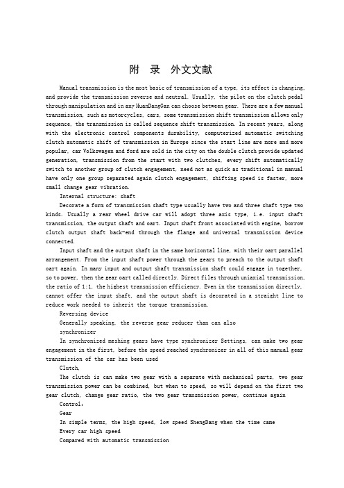
附录外文文献Manual transmission is the most basic of transmission of a type, its effect is changing, and provide the transmission reverse and neutral. Usually, the pilot on the clutch pedal through manipulation and in any HuanDangGan can choose between gear. There are a few manual transmission, such as motorcycles, cars, some transmission shift transmission allows only sequence, the transmission is called sequence shift transmission. In recent years, along with the electronic control components durability, computerized automatic switching clutch automatic shift of transmission in Europe since the start line are more and more popular, car Volkswagen and ford are sold in the city on the double clutch provide updated generation, transmission from the start with two clutches, every shift automatically switch to another group of clutch engagement, need not as quick as traditional in manual have only one group separated again clutch engagement, shifting speed is faster, more small change gear vibration.Internal structure: shaftDecorate a form of transmission shaft type usually have two and three shaft type two kinds. Usually a rear wheel drive car will adopt three axis type, i.e. input shaft transmission, the output shaft and oart. Input shaft front associated with engine, borrow clutch output shaft back-end through the flange and universal transmission device connected.Input shaft and the output shaft in the same horizontal line, with their oart parallel arrangement. From the input shaft power through the gears to preach to the output shaft oart again. In many input and output shaft transmission shaft could engage in together, so to power, then the gear oart called directly. Direct files through uniaxial transmission, the ratio of 1:1, the highest transmission efficiency. Even in the transmission directly, cannot offer the input shaft, and the output shaft is decorated in a straight line to reduce work needed to inherit the torque transmission.Reversing deviceGenerally speaking, the reverse gear reducer than can alsosynchronizerIn synchronized meshing gears have type synchronizer Settings, can make two gear engagement in the first, before the speed reached synchronizer in all of this manual gear transmission of the car has been usedClutch,The clutch is can make two gear with a separate with mechanical parts, two gear transmission power can be combined, but when to speed, so will depend on the first two gear clutch, change gear ratio, the two gear transmission power, continue again Control:GearIn simple terms, the high speed, low speed ShengDang when the time cameEvery car high speedCompared with automatic transmissionThis refers to the automatic transmission of traditional hydraulic transmission, namely through hydraulic torque converter and planetary gear transmission power automatic transmission.Advantages: transmission efficiency than automatic gearboxes for high, of course, theoretically can compare economical.maintenance will be cheaper than transmission.If you want to higher cost, can begin from both the row of convenience and high power附录外文文献的中文翻译手动变速器是汽车变速器中最基本的一种类型,其作用是改变传动比,并提供倒档和空档。
机械毕业设计英文外文翻译444手动变速器如何工作
机械毕业设计英⽂外⽂翻译444⼿动变速器如何⼯作附录How Manual Transmissions WorkIf you drive a stick-shift car, then you may have several questions floating in your head.How does the funny "H" pattern that I am moving this shift knob through have any relation to the gears inside the transmission? What is moving inside the transmission when I move the shifter?When I mess up and hear that horrible grinding sound, what is actually grinding? What would happen if I were to accidentally shift into reverse while I am speeding down the freeway? Would the entire transmission explode?In this article, we'll answer all of these questions and more as we explore the interior of a manual transmission.Cars need transmissions because of the physics of the gasoline engine. First, any engine has a redline --a maximum rpm value above which the engine cannot go without exploding. Second, if you have read How Horsepower Works, then you know that engines have narrow rpm ranges where horsepower and torque are at their maximum. For example, an engine might produce its maximum horsepower at 5,500 rpm. The transmission allows the gear ratio between the engine and the drive wheels to change as the car speeds up and slows down. You shift gears so the engine can stay below the redline and near the rpm band of its best performance.Ideally, the transmission would be so flexible in its ratios that the engine could always run at its single, best-performance rpm value. That is the idea behind the continuously variable transmission (CVT).A CVT has a nearly infinite range of gear ratios. In the past, CVTs could not compete with four-speed and five-speed transmissions in terms of cost, size and reliability, so you didn't see them in production automobiles. These days, improvements in design have made CVTs more common. The Toyota Prius is a hybrid car that uses a CVT.The transmission is connected to the engine through the clutch. The input shaft of the transmission therefore turns at the same rpm as the engine.A five-speed transmission applies one of five different gear ratios to the input shaft toproduce a different rpm value at the output shaft.A Very Simple TransmissionTo understand the basic idea behind a standard transmission, the diagram below shows a very simple two-speed transmission in neutral:Let's look at each of the parts in this diagram to understand how they fit together:The green shaft comes from the engine through the clutch. The green shaft and green gear are connected as a single unit. (The clutch is a device that lets you connect and disconnect the engine and the transmission. When you push in the clutch pedal, the engine and the transmission are disconnected so the engine can run even if the car is standing still. When you release the clutch pedal, the engine and the green shaft are directly connected to one another. The green shaft and gear turn at the same rpm as the engine.) The red shaft and gears are called the layshaft. These are also connected as a single piece, so all of the gears on the layshaft and the layshaft itself spin as one unit. The green shaft and the red shaft are directly connected through their meshed gears so that if the green shaft is spinning, so is the red shaft. In this way, the layshaft receives its power directly from the engine whenever the clutch is engaged.The yellow shaft is a splined shaft that connects directly to the drive shaft through the differential to the drive wheels of the car. If the wheels are spinning, the yellow shaft is spinning.The blue gears ride on bearings, so they spin on the yellow shaft. If the engine is offbut the car is coasting, the yellow shaft can turn inside the blue gears while the blue gears and the layshaft are motionless. Now, let's see what happens when you shift into first gear.First GearIn this picture, the green shaft from the engine turns the layshaft, which turns the blue gear on the right. This gear transmits its energy through the collar to drive the yellow drive shaft. Meanwhile, the blue gear on the left is turning, but it is freewheeling on its bearing so it has no effect on the yellow shaft.When the collar is between the two gears (as shown in the first figure), the transmission is in neutral. Both of the blue gears freewheel on the yellow shaft at the different rates controlled by their ratios to the layshaft.From this discussion, you can answer several questions:When you make a mistake while shifting and hear a horrible grinding sound, you are not hearing the sound of gear teeth mis-meshing. As you can see in these diagrams, all gear teeth are all fully meshed at all times. The grinding is the sound of the dog teeth trying unsuccessfully to engage the holes in the side of a blue gear.The transmission shown here does not have "synchros" (discussed later in the article), so if you were using this transmission you would have to double-clutch it. Double-clutching was common in older cars and is still common in some modern race cars. In double-clutching, you first push the clutch pedal in once to disengage the engine from the transmission. This takes the pressure off the dog teeth so you can move the collar into neutral. Then you release the clutch pedal and rev the engine to the "right speed." The right speed is the rpm value at which the engine should be running in the next gear. The idea is to get the blue gear of the next gear and the collar rotating at the same speed so that the dog teeth can engage. Then you push the clutch pedal in again and lock the collar into the new gear. At every gear change you have to press and release the clutch twice, hence the name "double-clutching."You can also see how a small linear motion in the gear shift knob allows you to change gears. The gear shift knob moves a rod connected to the fork. The fork slides the collar on the yellow shaft to engage one of two gears.In the next section, we'll take a look at a real transmission.A Real TransmissionThere are three forks controlled by three rods that are engaged by the shift lever. Looking at the shift rods from the top, they look like this in reverse, first and second gear: Keep in mind that the shift lever has a rotation point in the middle. When you push the knob forward to engage first gear, you are actually pulling the rod and fork for first gear back.You can see that as you move the shifter left and right you are engaging different forks (and therefore different collars). Moving the knob forward and backward moves the collar to engage one of the gears。
汽车变速器设计Transmission-design毕业论文外文文献翻译及原文
毕业设计(论文)外文文献翻译文献、资料中文题目:汽车变速器设计文献、资料英文题目:Transmission design文献、资料来源:文献、资料发表(出版)日期:院(部):专业:机械设计制造及其自动化班级:姓名:学号:指导教师:翻译日期: 2017.02.14毕业论文(设计)外文文献翻译汽车变速器设计我们知道,汽车发动机在一定的转速下能够达到最好的状态,此时发出的功率比较大,燃油经济性也比较好。
因此,我们希望发动机总是在最好的状态下工作。
但是,汽车在使用的时候需要有不同的速度,这样就产生了矛盾。
这个矛盾要通过变速器来解决。
汽车变速器的作用用一句话概括,就叫做变速变扭,即增速减扭或减速增扭。
为什么减速可以增扭,而增速又要减扭矩呢?设发动机输出的功率不变,功率可以表示为N=wT,其中w是转动的角速度,T是扭矩。
当N固定的时候,w与T是成反比的。
所以增速必减扭矩,减速必增扭矩。
汽车变速器齿轮传动就根据变速变扭的原理,分成各个档位对应不同的传动比,以适应不同的运行状况。
一般的手动变速器内设置输入轴、中间轴和输出轴,又称三轴式,另外还有倒档轴。
三轴式是变速器的主体结构,输入轴的转速也就是发动机的转速,输出轴转速则是中间轴与输出轴之间不同齿轮啮合所产生的转速。
不同的齿轮啮合就有不同的传动比,也就有了不同的转速。
例如郑州日产ZN6481W2G型SUV车手动变速器,它的传动比分别是:1档3.704:1;2档2.202:1;3档1.414:1;4档1:1;5档(超速档)0.802:1。
当汽车启动司机选择1档时,拨叉将1/2档同步器向后接合1档齿轮并将它锁定输出轴上,动力经输入轴、中间轴和输出轴上的1档齿轮,1档齿轮带动输出轴,输出轴将动力传递到传动轴上(红色箭头)。
典型1档变速齿轮传动比是3:1,也就是说输入轴转3圈,输出轴转1圈。
当汽车增速司机选择2档时,拨叉将1/2档同步器与1档分离后接合2档齿轮并锁定输出轴上,动力传递路线相似,所不同的是输出轴上的1档齿轮换成2档齿轮带动输出轴。
手动变速箱的工作原理控制形式
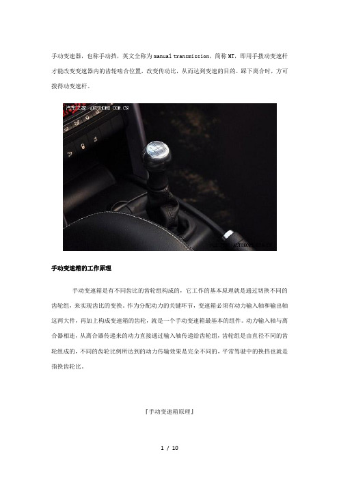
手动变速器,也称手动挡,英文全称为manual transmission,简称MT,即用手拨动变速杆才能改变变速器内的齿轮啮合位置,改变传动比,从而达到变速的目的。
踩下离合时,方可拨得动变速杆。
手动变速箱的工作原理手动变速箱是有不同齿比的齿轮组构成的,它工作的基本原理就是通过切换不同的齿轮组,来实现齿比的变换。
作为分配动力的关键环节,变速箱必须有动力输入轴和输出轴这两大件,再加上构成变速箱的齿轮,就是一个手动变速箱最基本的组件。
动力输入轴与离合器相连,从离合器传递来的动力直接通过输入轴传递给齿轮组,齿轮组是由直径不同的齿轮组成的,不同的齿轮比例所达到的动力传输效果是完全不同的,平常驾驶中的换挡也就是指换齿轮比。
『手动变速箱原理』接下来,让我们通过一个简单的模型来给大家讲讲,手动变速箱换挡的原理。
下图是一个简易的3轴2挡变速箱的结构模型。
输入轴(绿色)也叫第一轴,通过离合器和发动机相连,轴和上面的齿轮是一个硬连接的部件。
红色齿轮轴叫做中间轴。
输入轴和中间轴的两个齿轮是处于常啮合状态的,因此当输入轴旋转时就会带动中间轴的旋转。
黄色则是输出轴,它也叫第二轴直接和驱动轴相连(只针对后轮驱动,前驱一般为两轴),再通过差速器来驱动汽车。
当车轮转动时同样会带着花键轴一起转动,此时,轴上的蓝色齿轮可以在花键轴上发生相对自由转动。
因此,在发动机停止,而车轮仍在转动时,蓝色齿轮和中间轴出在静止状态,而花键轴则随车轮转动。
这个原理和自行车后轴的飞轮很相似。
蓝色齿轮和花键轴是由套筒来连接的,套筒随着花键轴转动,但同时也可以在花键轴上左右自由滑动来啮合齿轮。
说完这些,换挡的过程就很好理解了,当套筒和蓝色齿轮相连时,发动机的动力就会通过中间轴传递到输出轴上,在这同时,左边的蓝色齿轮也在自由旋转,但由于没有和套筒啮合,所以它不对花键轴产生影响。
而如果套筒在两个蓝色齿轮之间时,变速箱在空挡位置,此时两个蓝色齿轮都在花键轴上自由转动,互不干涉。
- 1、下载文档前请自行甄别文档内容的完整性,平台不提供额外的编辑、内容补充、找答案等附加服务。
- 2、"仅部分预览"的文档,不可在线预览部分如存在完整性等问题,可反馈申请退款(可完整预览的文档不适用该条件!)。
- 3、如文档侵犯您的权益,请联系客服反馈,我们会尽快为您处理(人工客服工作时间:9:00-18:30)。
附录How Manual Transmissions WorkIf you drive a stick-shift car, then you may have several questions floating in your head.How does the funny "H" pattern that I am moving this shift knob through have any relation to the gears inside the transmission? What is moving inside the transmission when I move the shifter?When I mess up and hear that horrible grinding sound, what is actually grinding? What would happen if I were to accidentally shift into reverse while I am speeding down the freeway? Would the entire transmission explode?In this article, we'll answer all of these questions and more as we explore the interior of a manual transmission.Cars need transmissions because of the physics of the gasoline engine. First, any engine has a redline --a maximum rpm value above which the engine cannot go without exploding. Second, if you have read How Horsepower Works, then you know that engines have narrow rpm ranges where horsepower and torque are at their maximum. For example, an engine might produce its maximum horsepower at 5,500 rpm. The transmission allows the gear ratio between the engine and the drive wheels to change as the car speeds up and slows down. You shift gears so the engine can stay below the redline and near the rpm band of its best performance.Ideally, the transmission would be so flexible in its ratios that the engine could always run at its single, best-performance rpm value. That is the idea behind the continuously variable transmission (CVT).A CVT has a nearly infinite range of gear ratios. In the past, CVTs could not compete with four-speed and five-speed transmissions in terms of cost, size and reliability, so you didn't see them in production automobiles. These days, improvements in design have made CVTs more common. The Toyota Prius is a hybrid car that uses a CVT.The transmission is connected to the engine through the clutch. The input shaft of the transmission therefore turns at the same rpm as the engine.A five-speed transmission applies one of five different gear ratios to the input shaft toproduce a different rpm value at the output shaft.A Very Simple TransmissionTo understand the basic idea behind a standard transmission, the diagram below shows a very simple two-speed transmission in neutral:Let's look at each of the parts in this diagram to understand how they fit together:The green shaft comes from the engine through the clutch. The green shaft and green gear are connected as a single unit. (The clutch is a device that lets you connect and disconnect the engine and the transmission. When you push in the clutch pedal, the engine and the transmission are disconnected so the engine can run even if the car is standing still. When you release the clutch pedal, the engine and the green shaft are directly connected to one another. The green shaft and gear turn at the same rpm as the engine.) The red shaft and gears are called the layshaft. These are also connected as a single piece, so all of the gears on the layshaft and the layshaft itself spin as one unit. The green shaft and the red shaft are directly connected through their meshed gears so that if the green shaft is spinning, so is the red shaft. In this way, the layshaft receives its power directly from the engine whenever the clutch is engaged.The yellow shaft is a splined shaft that connects directly to the drive shaft through the differential to the drive wheels of the car. If the wheels are spinning, the yellow shaft is spinning.The blue gears ride on bearings, so they spin on the yellow shaft. If the engine is offbut the car is coasting, the yellow shaft can turn inside the blue gears while the blue gears and the layshaft are motionless.Now, let's see what happens when you shift into first gear.First GearIn this picture, the green shaft from the engine turns the layshaft, which turns the blue gear on the right. This gear transmits its energy through the collar to drive the yellow drive shaft. Meanwhile, the blue gear on the left is turning, but it is freewheeling on its bearing so it has no effect on the yellow shaft.When the collar is between the two gears (as shown in the first figure), the transmission is in neutral. Both of the blue gears freewheel on the yellow shaft at the different rates controlled by their ratios to the layshaft.From this discussion, you can answer several questions:When you make a mistake while shifting and hear a horrible grinding sound, you are not hearing the sound of gear teeth mis-meshing. As you can see in these diagrams, all gear teeth are all fully meshed at all times. The grinding is the sound of the dog teeth trying unsuccessfully to engage the holes in the side of a blue gear.The transmission shown here does not have "synchros" (discussed later in the article), so if you were using this transmission you would have to double-clutch it. Double-clutching was common in older cars and is still common in some modern race cars. In double-clutching, you first push the clutch pedal in once to disengage the engine from the transmission. This takes the pressure off the dog teeth so you can move the collar into neutral. Then you release the clutch pedal and rev the engine to the "right speed." The right speed is the rpm value at which the engine should be running in the next gear. The idea is to get the blue gear of the next gear and the collar rotating at the same speed so that the dog teeth can engage. Then you push the clutch pedal in again and lock the collar into the new gear. At every gear change you have to press and release the clutch twice, hence the name "double-clutching."You can also see how a small linear motion in the gear shift knob allows you to change gears. The gear shift knob moves a rod connected to the fork. The fork slides the collar on the yellow shaft to engage one of two gears.In the next section, we'll take a look at a real transmission.A Real TransmissionThere are three forks controlled by three rods that are engaged by the shift lever. Looking at the shift rods from the top, they look like this in reverse, first and second gear: Keep in mind that the shift lever has a rotation point in the middle. When you push the knob forward to engage first gear, you are actually pulling the rod and fork for first gear back.You can see that as you move the shifter left and right you are engaging different forks (and therefore different collars). Moving the knob forward and backward moves the collar to engage one of the gears。