机械专业毕业设计外文翻译外文文献
孙明明 外文资料翻译
毕业设计(论文)外文资料翻译学院:机械电子工程学院专业:机械设计制造及其自动化姓名:孙明明学号: 070501504外文出处: The advantages of PLC control,filed under PLC Articles附件: 1.外文资料翻译译文;2.外文原文。
(用外文写)附件1:外文资料翻译译文PLC的控制优势任何控制系统从概念到进入工厂工作都要经历四个阶段。
PLC系统在每一个阶段都有优势。
第一阶段是设计,对工厂的需要进行研究和制定控制策略,传统的运行平台的设计和制造必须在设计进行前完成。
PLC系统仅仅需要的是一个模糊的关于机器的可能大小的想法和I/O数量的要求(多少输入和输出接口)。
在这个阶段输入和输出芯片十分便宜,所以可以内置一个很健全的备用容量,它允许用来补充遗漏项目和为未来的扩充做准备。
其次是设计。
传统的方案是,每一项工作都是“一次成型”这不可避免的造成了工程拖延和增加成本。
一个的PLC系统使用最简单的标准件螺栓连接在一起。
在这样的连接下开始编写 PLC程序(或者至少是写入详细的程序规范)。
下一阶段是安装,安装是一种繁琐和昂贵的工作,例如安装传感器、执行器、限制开关系统和主机的连接。
分布式PLC系统使用串行链路式的预编译,测试界面可以简化安装它带来了巨大的成本优势。
PLC的程序多数在这个阶段完成。
最后是调试,而这正是PLC真正的优势被发掘的部分。
没有任何设备在第一次就正常工作。
人性就是这样,总会有一些疏漏。
与传统的系统变动情况的耗时和昂贵相比,PLC的设计师提供了系的内置备用内存容量、备用I/O和一些备用多芯电缆线,多数的变动能迅速和相对便宜的完成。
另外一个好处是,所有的变化PLC都有记录,程序的调试和修改不会因为没有被记录而遗失,这是一个经常发生在常规系统中的问题。
还有一个额外的第五阶段,维护,一旦启动工作,并移交生产就产生了维护的问题。
所有设备都有缺点,大多数设备在错误的模式中度过了它们的大部分的时间。
机械专业毕业设计外文翻译12

Development of a high-performance laser-guided deep-holeboring tool: optimal determination of reference origin for precise guidingAbstractA laser-guided deep-hole boring tool using piezoelectric actuators was developed to prevent hole deviation. To extend the depth o controll able boring further, the following were improved. The tool’s guiding error, caused by misalignment of the corner cube prism and the mirror in the optical head from the spindle axis, was eliminated using an adjustment jig that determined the reference origins of the two position-sensitive detectors (PSDs) precisely. A single-edge counter-boring head is used instead of the double-edge head used up to now The former was thought to be better in attitude control than the latter. A new boring bar, which was lower in rigidity and better in Controllability of tool attitude, was used. Experiments were conducted to examine the performance of the new tool in detail and to determin its practical application, using duralumin (A2017-T4) workpieces with a prebored 108-mm diameter hole. The experiments were performed with a rotating tool–stationary workpiece system. Rotational speed was 270 rpm and feed was 0.125 mm/rev. Tool diameter was 110 mm Asaresult,controlled boring becomes possible up to a depth of 700 mm under the stated experimental conditions.700 mm is the maximum machinable length of the machine tool. The tool can be put to practical use.Keywords: Deep hole-boring; Adaptive control; Laser application1.IntroductionTo bore a precise straight hole, a deep-hole boring tool should be guided toward a target. From this point of view, the laser-guided deep-hole boring tool was developed [1–6]. The latest tool using piezoelectric actuators could be guided to go straight toward the target,despitedisturbances up to a depth of 388 mm [6].In the present paper, before the performance of the tool is examined, the following points are improved to extend the depth. The tool’s guiding error, caused by misalignment of the corner cube prism and the mirror in the optical head from the spindle axis, is eliminated using a jig that deter- mines the reference origins of the two position-sensitive detectors (PSDs) precisely. A single-edge counter-boring head is used instead of the double-edge head used up to now. The former is thought to be better in attitude control than the latter. A new boring bar, which is 15% lower in both bending and torsional rigidity and which is better in controllability of tool attitude, is used.2. Experimental apparatusFigs. 1 and 2 show the tool head and the experimental apparatus, respectively [6]. The head is the same as that used in experiments up to now. One cutting edge of the double-edge counter-boring head is replaced by a guide pad,And six guide pads are removed[4].By removal of the guide pads, cutting oil is supplied better between the other guide pads and hole wall. The tool head consists of an optical head, a counter-boring head, piezoelectric actuators, and an actuator holder (Fig. 1). The optical head is attached to the front surface of the counter-boring head through an adjust- ment jig. The actuator holder is connected to a rotation stopper 14 behind the tool head by two parallel plates of phosphor bronze 6 (Fig. 2). A laser source 11, and PSDs 9, 10 are set in front of the tool. The rectangular coordinates XAnd Y are set on a plane perpendicular to the spindle rotation axis(Z-axis).The optical distancebetween a dichroic mirror in the optical head and PSD 10 for measuring tool inclina- tion is 2,040 mm [2].3. Method for detection of tool position and its inclinationFig. 3 shows the method used for measuring the tool position and its inclination. The laser beam, radiated from an argon laser, reaches the dichroic mirror 6 through the beam expander 5 and the half mirror 1. The dichroic mirror separates the two beams of wavelengths 514 nm (green) and 488 nm (blue). The green beam for measuring tool position passes through the dichroic mirror 6 and reachesthe corner cube prism 8. The reflected beam passes again through 6 and is deflected by the half mirror 1 toward dichroic mirror 2. By passing through the dichroic mirror 2, it reaches the PSD 9 used for measuring tool position. The blue beam for measuring tool inclination reaches the dichroic mirror 7 with an angle of incidence equal to 0°. The dichroic mirror 7 reflects the blue beam and trans- mits parts of the green beam, which are not completelyseparated by the dichroic mirror 6. The returning beam from the dichroic mirror 7 is deflected by the mirrors 6, 1, and 2, then passing through the dichroic mirror 4, and reaches the PSD 10 for measuring tool inclination. Re- flective characteristics of dichroic mirror 4 differs from that of dichroic mirror 7.4. Acquisition of data for controlling the toolData for tool attitude control are acquired from the two PSDs for tool position and its inclination every rotation of the counter-boring head. Until now, outputs of the two PSDs (measuring tool position and its inclination) some- times did not correspond well to the measured hole devia- tion. To determine what causes this, the following is exam- ined. The tool head with the optical head is supported by two V-blocks and is aligned on the Z-axis at the same longitudinal position as in the experiment. Then, the laser beam is radiated, and the optical head is rotated manually.Fig. 4 shows variations of outputs of two PSDs with encoder pulse during one rotation of the optical head fixed on the counter-boring head. Theoretically, outputs of two PSDs are constant during one rotation of the optical head corresponding to a 1,400 pulse of output of an encoder. Changes of X- and Y-outputs of tool position are caused by change of darkness of the laser spot because of interference and polarization of the laser beam. Changes of X- and Y- outputs of tool inclination are caused by inclination of the reflecting mirror in the optical head from the Z-axis. From the last experiment [6] on, tool position and its inclination are measured at rotational pulse position 700, where the brightness of the two PSDs are preferable at the same time.5. Misalignment of the optical parts in the optical headEven if the laser source and the PSDs for tool position and its inclination are aligned on Z-axis, hole deviation appeared. To discover its cause, the misalignment of the corner cube prism and inclination of reflecting mirror in the optical head from the Z-axis are examined.Fig. 5 shows all cases of alignment errors. Fig. 5(a) shows that the corner cube prism and the reflecting mirror are precisely aligned on the Z-axis. Figs. 5(b) and 5(c) are, the cases in which the corner cube prism is displaced by and the reflecting mirror is inclined byfrom the Z-axis, respectively.IncaseofFig.5(d),errorsofFigs.5(b)and(c) occur together. Fig. 5(e) shows the case when the optical head is inclined byduring the setup of the counter-boring head. Fig. 5(f) is the worst case, when all errors occur together. These errors cannot be eliminated by conventional adjustment. Therefore a new guiding strategy is developed to ensure that the tool can be guided straight, even if errors should occur.6. Optimal setup of reference origin for precise guidingFig. 6 shows the optimal setup method of reference origins. The laser source is aligned on the Z-axis [Fig. 6(a)] [6]. The optical head is fixed to the front surface of a cylindrical alignment jig through an adjustment jig. The alignment jig is inserted into the guide bush, which is fixed on a machine table, and the centers of both alignment jig and the optical head are aligned on Z-axis. Then the laser beam is radiated. Reflected beams reach the PSDs for tool position and its inclination. When the cylinder is rotated by hand, the rotational position, at which the output is most reliable, can be found. Next, the PSDs are moved until the spots lie at their centers. This position corresponds to the pulse position 700 of the encoder. The centers are reference origins for tool position and its inclination.At this rotational position,the optical head is fixed to the counter-boring head using the adjustment jig [Fig.6(b)].When the control starts, the tool head follows the alignment jig’s axis.7. Mechanism of tool displacementFig. 7 shows the mechanism of tool displacement. Fig. 7(a) shows the normal cutting condition [7]. The cutting force P is acting on the cutting edge and is counterbalanced by the guide pads. Fig. 7(b) shows the case where the tool is to correct for a deviation. A chain double-dashed line shows the hole wall before correction of hole deviation. A Directed line shows the direction of the correction.When the tool is controlled to incline toward the direction of the directed line, a cutting edge set ahead of the guide pads overcuts the hole wall. When the guide pad on the opposite side comes to the position of the overcutting zone, the cutting edge leaves a noncutting zone on the hole wall Opposite the overcutting zone.As a result,tool shifts toward the direction of the directed line.In the case of double-edge counter-boring head, the cut- ting force acting on one cutting edge is balanced by the force that acts on the other cutting edge [7]. As a result, the head is easy to vibrate, and the mechanism of tool displace- ment does not function well.Form: Precision Engineering 24 (2000) 9–14 开发高性能的激光制导deep-holeboring工具:最佳测定参考来源精确指导摘要激光制导深孔钻具使用压电致动器是防止孔偏差。
机械工程专业外文文献及翻译

机械工程专业外文文献及翻译文献一(外文标题)
摘要:
该文献研究了机械工程领域中的某个具体问题。
通过实验方法和数学模型的分析,作者得出了一些有意义的结论。
本文介绍了作者的研究方法和结果,并讨论了其在机械工程领域的应用前景。
翻译:
(将文献的主要内容用简洁准确的语言翻译成中文)
文献二(外文标题)
摘要:
该文献探讨了机械工程领域中的另一个重要问题。
通过实证分析和理论推导,作者提出了解决方案,并对其进行了验证。
本文阐述了作者的方法和实验结果,并探讨了其在实践中的应用潜力。
翻译:
(将文献的主要内容用简洁准确的语言翻译成中文)
文献三(外文标题)
摘要:
该文献研究了机械工程领域中的另一个新颖课题。
作者通过数
值模拟和实验验证,得出了一些有趣的发现。
本文介绍了作者的研
究过程和结果,并讨论了其对机械工程领域的影响。
翻译:
(将文献的主要内容用简洁准确的语言翻译成中文)
总结
本文档介绍了三篇机械工程专业的外文文献,包括摘要和翻译。
这些文献都对机械工程领域中的不同问题进行了研究,并提出了相
关的解决方案和发现。
希望这些文献能为机械工程专业的学生和研
究人员提供有价值的参考和启发。
机械专业毕业设计外文翻译10
翻译部分英文部分ADV ANCED MACHINING PROCESSESAs the hardware of an advanced technology becomes more complex, new and visionary approaches to the processing of materials into useful products come into common use. This has been the trend in machining processes in recent years.. Advanced methods of machine control as well as completely different methods of shaping materials have permitted the mechanical designer to proceed in directions that would have been totally impossible only a few years ago.Parallel development in other technologies such as electronics and computers have made available to the machine tool designer methods and processes that can permit a machine tool to far exceed the capabilities of the most experienced machinist.In this section we will look at CNC machining using chip-making cutting tools. CNC controllers are used to drive and control a great variety of machines and mechanisms, Some examples would be routers in wood working; lasers, plasma-arc, flame cutting, and waterjets for cutting of steel plate; and controlling of robots in manufacturing and assembly. This section is only an overview and cannot take the place of a programming manual for a specific machine tool. Because of the tremendous growth in numbers and capability of comp uters ,changes in machine controls are rapidly and constantly taking place. The exciting part of this evolution in machine controls is that programming becomeseasier with each new advanced in this technology.Advantages of Numerical ControlA manually operated machine tool may have the same physical characteristics as a CNC machine, such as size and horsepower. The principles of metal removal are the same. The big gain comes from the computer controlling the machining axes movements. CNC-controlled machine tools can be as simple as a 2-axis drilling machining center (Figure O-1). With a dual spindle machining center, the low RPM, high horsepower spindle gives high metal removal rates. The high RPM spindle allows the efficient use of high cutting speed tools such as diamonds and small diameter cutters (Figure O-2). The cutting tools that remove materials are standard tools such as milling cutters, drills, boring tools, or lathe tools depending on the type of machine used. Cutting speeds and feeds need to be correct as in any other machining operation. The greatest advantage in CNC machining comes from the unerring and rapid positioning movements possible. A CNC machine does dot stop at the end of a cut to plan its next move; it does not get fatigued; it is capable of uninterrupted machining error free, hour after hour. A machine tool is productive only while it is making chips.Since the chip-making process is controlled by the proper feeds and speeds, time savings can be achieved by faster rapid feed rates. Rapid feeds have increased from 60 to 200 to 400 and are now often approaching 1000 inches per minute (IPM). These high feed rates can pose a safety hazard to anyone within the working envelope of the machine tool.Complex contoured shapes were extremely difficult to product prior to CNC machining .CNC has made the machining of these shapes economically feasible. Design changes on a part are relatively easy to make by changing the program that directs the machine tool.A CNC machine produces parts with high dimensional accuracy and close tolerances without taking extra time or special precautions, CNC machines generally need less complex work-holding fixtures, which saves time by getting the parts machined sooner. Once a program is ready and production parts, each part will take exactly the same amount of time as the previous one. This repeatability allows for a very precise control of production costs. Another advantage of CNC machining is the elimination of large inventories; parts can be machined as needs .In conventional production often a great number of parts must be made at the same time to be cost effective. With CNC even one piece can be machined economically .In many instances, a CNC machine can perform in one setup the same operations that would require several conventional machines.With modern CNC machine tools a trained machinist can program and product even a single part economically .CNC machine tools are used in small and large machining facilities and range in size from tabletop models to huge machining centers. In a facility with many CNC tools, programming is usually done by CNC programmers away from the CNC tools. The machine control unit (MCU) on the machine is then used mostly for small program changes or corrections. Manufacturing with CNC tools usually requires three categories of persons. The first is the programmer, who is responsible for developing machine-ready code. The next person involved is the setup person, who loads the raw stork into the MCU, checks that the co rrect tools are loaded, and makes the first part. The third person is the machine and unloads the finished parts. In a small company, one person is expected to perform all three of these tasks.CNC controls are generally divided into two basic categories. One uses a ward address format with coded inputs such as G and M codes. The other users a conversational input; conversational input is also called user-friendly or prompted input. Later in this section examples of each of these programming formats in machining applications will be describes.CAM and CNCCAM systems have changed the job of the CNC programmer from one manually producing CNC code to one maximizing the output of CNC machines. Since CNC machine tools are made by a great number of manufacturers, many different CNC control units are in use. Control units from different manufacturers use a variety of program formats and codes. Many CNC code words are identical for different controllers, but a great number vary from one to another.To produce an identical part on CNC machine tools with different controllers such as one by FANCU, OKUMA or DYNAPATH, would require completely different CNC codes. Each manufacturer is constantly improving and updating its CNC controllers. These improvements often include additional code words plus changes in how the existing code works.A CAM systems allows the CNC programmer to concentrate on the creation of an efficient machining process, rather then relearning changed code formats. A CNC programmer looks atthe print of a part and then plans the sequence of machining operations necessary to make it (Figure O-3). This plan includes everything, from the selection of possible CNC machine tools, to which tooling to use, to how the part is held while machining takes place. The CNC programmer has to have a thorough understanding of all the capacities and limitations of the CNC machine tools that a program is to be made for. Machine specifications such as horsepower, maximum spindle speeds, workpiece weight and size limitations, and tool changer capacity are just some of the considerations that affect programming.Another area of major importance to the programmer is the knowledge of machining processes. An example would be the selection of the surface finish requirement specified in the part print. The sequence of machining processes is critical to obtain acceptable results. Cutting tool limitations have to be considered and this requires knowledge of cutting tool materials, tool types, and application recommendations.A good programmer will spend a considerable amount of time in researching the rapidly growing volume of new and improved tools and tool materials. Often the tool that was on the cutting edge of technology just two years ago is now obsolete. Information on new tools can come from catalogs or tool manufacturers' tooling engineers. Help in tool selection or optimum tool working conditions can also be obtained from tool manufacturer software. Examples would be Kennametal's "TOOLPRO", software designed to help select the best tool grade, speed, and feed rates for different work materials in turning application. Another very important feature of "TOOLPRO" is the display of the horsepower requirement for each machining selection. This allow the programmer to select a combination of cutting speed, feed rate, and depth of cut that equals the machine's maximum horsepower for roughing cuts. For a finishing cut, the smallest diameter of the part being machined is selected and then the cutting speed varied until the RPM is equal to the maximum RPM of the machine. This helps in maximizing machining efficiency. Knowing the horsepower requirement for a cut is critical if more than one tool is cutting at the same time.Software for a machining center application would be Ingersoll Tool Company's "Actual Chip Thickness", a program used to calculate the chip thickness in relation to feed-per-tooth for a milling cutter, especially during a shallow finishing cut. Ingersoll's "Rigidity Analysis" software ealculates tool deflection for end mills as a function of tool stiffness and tool force.To this point we looked at some general qualifications that a programmer should possess. Now we examine how a CAM system works. Point Control Company's SmartCam system uses the following approach. First, the programmer makes a mental model of the part to be machined. This includes the kind of machining to be performed-turning or milling. Then the part print is studied to develop a machining sequence, roughing and finishing cuts, drilling, tapping, and boring operations. What work-holding device is to be used, a vise or fixture or clamps? After these considerations, computer input can be started. First comes the creation of a JOBPLAN. This JOBPLAN consists of entries such as inch or metric units, machine type, part ID, type of workpiece material, setup notes, and a description of the required tools.This line of information describes the tool by number, type, and size and includes theappropriate cutting speed and feed rate. After all the selected tools are entered, the file is saved.The second programming step is the making of the part. This represents a graphic modeling of the projected machining operation. After selecting a tool from the prepared JOBPLAN, parameters for the cutting operation are entered. For a drill, once the coordinate location of the hole and the depth are given, a circle appears on that spot. If the location is incorrect, the UNDO command erases this entry and allows you to give new values for this operation. When an end mill is being used, cutting movements (toolpath) are usually defined as lines and arcs. As a line is programmed, the toolpath is graphically displayed and errors can be corrected instantly.At any time during programming, the command SHOWPATH will show the actual toolpath for each of the programmed tools. The tools will be displayed in the sequence in which they will be used during actual machining. If the sequence of a tool movement needs to be changed, a few keystrokes will to that.Sometimes in CAM the programming sequence is different from the actual machining order. An example would be the machining of a pocket in a part. With CAM, the finished pocket outline is programmed first, then this outline is used to define the ro ughing cuts to machine the pocket. The roughing cuts are computer generated from inputs such as depth and width of cut and how much material to leave for the finish cut. Different roughing patterns can be tried out to allow the programmer to select the most efllcient one for the actual machining cuts. Since each tool is represented by a different color, it is easy to observe the toolpath made by each one.A CAM system lets the programmer view the graphics model from varying angles, such as a top, front, side, or isometric view. A toolpath that looks correct from a top view, may show from a front view that the depth of the cutting tool is incorrect. Changes can easily be made and seen immediately.When the toolpath and the sequence of operations are satisfactory, machine ready code has to be made. This is as easy as specifying the CNC machine that is to be used to machine the part. The code generator for that specific CNC machin e during processing accesses four different files. The JOBPLAN file for the tool information and the GRAPHICE file for the toolpath and cutting sequence. It also uses the MACHINE DEFINE file which defines the CNC code words for that specific machine. This file also supplies data for maximum feed rates, RPM, toolchange times, and so on. The fourth file taking part in the code generating process is the TEMPLATE file. This file acts like a ruler that produces the CNC code with all of its parts in the right place and sequence. When the code generation is complete, a projected machining time is displayed. This time is calculated from values such as feed rates and distances traveled, noncutting movements at maximum feed rates between points, tool change times, and so on. The projected machining time can be revised by changing tooling to allow for higher metal removal rates or creating a more efficient toolpath. This display of total time required can also be used to estimate production costs. If more then one CNC machine tool is available to machine this part, making code and comparing the machining time may show that one machine is more efficient than the others.CAD/CAMAnother method of creating toolpath is with the use of a Computer-aided Drafting (CAD) file. Most machine drawings are created using computers with the description and part geometry stored in the computer database. SmartCAM, though its CAM CONNECTION, will read a CAD file and transfer its geometry represents the part profile, holes, and so on. The programmer still needs to prepare a JOBPLAN with all the necessary tools, but instead of programming a profile line by line, now only a tool has to be assigned to an existing profile. Again, using the SHOWPA TH function will display the toolpath for each tool and their sequence. Constant research and developments in CAD/CAM interaction will change how they work with each other. Some CAD and CAM programs, if loaded on the same computer, make it possible to switch between the two with a few keystrokes, designing and programming at the same time.The work area around the machine needs to be kept clean and clear of obstructions to prevent slipping or tripping. Machine surfaces should not be used as worktables. Use proper lifting methods to handle heavy workpieces, fixtures, or heavy cutting tools. Make measurements only when the spindle has come to a complete standstill. Chips should never be handled with bare hands.Before starting the machine make sure that the work-holding device and the workpiece are securely fastened. When changing cutting tools, protect the workpiece being machined from damage, and protect your hands from sharp cutting edges. Use only sharp cutting tools. Check that cutting tools are installed correctly and securely.Do not operate any machine controls unless you understand their function and what the y will do.The Early Development Of Numerically Controlled Machine ToolsThe highly sophisticated CNC machine tools of today, in the vast and diverse range found throughout the field of manufacturing processing, started from very humble beginnings in a number of the major industrialized countries. Some of the earliest research and development work in this field was completed in USA and a mention will be made of the UK's contribution to this numerical control development.A major problem occurred just after the Second World War, in that progress in all areas of military and commercial development had been so rapid that the levels of automation and accuracy required by the modern industrialized world could not be attained from the lab our intensive machines in use at that time. The question was how to overcome the disadvantages of conventional plant and current manning levels. It is generally ackonwledged that the earliest work into numerical control was the study commissioned in 1947 by the US governme nt. The study's conclusion was that the metal cutting industry throughout the entire country could not copy with the demands of the American Air Force, let alone the rest of industry! As a direct result of the survey, the US Air Force contracted the Persons Corporation to see if they could develop a flexible, dynamic, manufacturing system which would maximize productivity. TheMassachusetts Institute of Technology (MIT) was sub-contracted into this research and development by the Parsons Corporation, during the period 1949-1951,and jointly they developed the first control system which could be adapted to a wide range of machine tools. The Cincinnati Machine Tool Company converted one of their standard 28 inch "Hydro-Tel" milling machines or a three-axis automatic milling made use of a servo-mechanism for the drive system on the axes. This machine made use of a servomechanism for the drive system on the axes, which controlled the table positioning, cross-slide and spindle head. The machine cab be classified as the first truly three axis continuous path machine tool and it was able to generate a required shape, or curve, by simultaneous slide way motions, if necessary.At about the same times as these American advances in machine tool control were taking Place, Alfred Herbert Limited in the United Kingdom had their first Mutinous path control system which became available in 1956.Over the next few years in both the USA and Europe, further development work occurred. These early numerical control developments were principally for the aerospace industry, where it was necessary to cut complex geometric shapes such as airframe components and turbine blades. In parallel with this development of sophisticated control systems for aerospace requirements, a point-to-point controller was developed for more general machining applications. These less sophisticated point-to-point machines were considerably cheaper than their more complex continuous path cousins and were used when only positional accuracy was necessary. As an example of point-to-point motion on a machine tool for drilling operations, the typical movement might be fast traverse of the work piece under the drill's position-after drilling the hole, anther rapid move takes place to the next hole's position-after retraction of the drill. Of course, the rapid motion of the slideways could be achieved by each axis in a sequential and independent manner, or simultaneously. If a separate control was utilisec for each axis, the former method of table travel was less esse ntial to avoid any backlash in the system to obtain the required degree of positional accuracy and so it was necessary that the approach direction to the next point was always the same.The earliest examples of these cheaper point-to-point machines usually did not use recalculating ball screws; this meant that the motions would be sluggish, and sliderways would inevitably suffer from backlash, but more will be said about this topic later in the chapter.The early NC machines were, in the main, based upon a modified milling machine with this concept of control being utilized on turning, punching, grinding and a whole host of other machine tools later. Towards the end of the 1950s,hydrostatic slideways were often incorporated for machine tools of highly precision, which to sonic extent overcame the section problem associated with conventional slideway response, whiles averaging-out slideway inaccuracy brought about a much increased preasion in the machine tool and improved their control characteristics allows "concept of the machining center" was the product of this early work, as it allowed the machine to manufacture a range of components using a wide variety of machining processes at a single set-up, without transfer of workpieces to other variety machine tools. A machining center differed conceptually in its design from that of a milling machine, In that thecutting tools could be changed automatically by the transfer machanism, or selector, from the magazine to spindle, or vice versa.In this ductively and the automatic tool changing feature enabled the machining center to productively and efficiently machine a range of components, by replacing old tools for new, or reselecting the next cutter whilst the current machining process is in cycle.In the mid 1960s,a UK company, Molins, introduced their unique "System 24" which was meant represent the ability of a system to machine for 24 hours per day. It could be thought of as a "machining complex" which allowed a series of NC single purpose machine tools to be linked by a computerized conveyor system. This conveyor allowed the work pieces to be palletized and then directed to as machine tool as necessary. This was an early, but admirable, attempt at a form of Flexible manufacturing System concept, but was unfortunately doomed to failure. Its principal weakness was that only a small proportion of component varieties could be machine at any instant and that even fewer work pieces required the same operations to be performed on them. These factors meant that the utilization level was low, coupled to the fact that the machine tools were expensive and allowed frequent production bottlenecks of work-in-progress to arise, which further slowed down the whole operation.The early to mid-1970s was a time of revolutionary in the area of machine tool controller development, when the term computerized numerical control (CNC) became a reality. This new breed of controllers gave a company the ability to change work piece geometries, together with programs, easily with the minimum of development and lead time, allowing it to be economically viable to machine small batches, or even one-off successfully. The dream of allowing a computerized numerical controller the flexibility and ease of program editing in a production environment became a reality when two ralated factors occurred.These were:the development of integrated circuits, which reduces electronics circuit size, giving better maintenance and allowing more standardization of desing; that general purpose computers were reduced in size coupled to the fact that their cost of production had fallen considerably.The multipie benefits of cheaper electorics with greater reliability have result in the CNC fitted to the machine tools today, with the power and sophistication progtessing considerably in the last few years, allowing an almost artificial intelligence(AI) to the latest systems. Over the years, the machine tools builders have produced a large diversity in the range of applications of CNC and just some of those development will be reviewed in V olume Ⅲ。
机械专业毕业设计外文翻译1

本科毕业设计(本科毕业论文)外文文献及译文文献、资料题目:High-rise Tower Crane designed文献、资料来源:期刊(著作、网络等)文献、资料发表(出版)日期:2000.3.25院(部):机电工程学院专业:机电工程及自动化High-rise Tower Crane designed under Turbulent Winds At present, construction of tower cranes is an important transport operations lifting equipment, tower crane accident the people's livelihood, major hazards, and is currently a large number of tower crane drivers although there are job permits, due to the lack of means to monitor and review the actual work of a serious violation . Strengthen the inspection and assessment is very important. Tower crane tipping the cause of the accident can be divided into two aspects: on the one hand, as a result of the management of tower cranes in place, illegal operation, illegal overloading inclined cable-stayed suspended widespread phenomenon; Second, because of the tower crane safety can not be found in time For example,Took place in the tower crane foundation tilt, micro-cracks appear critical weld, bolts loosening the case of failure to make timely inspection, maintenance, resulting in the continued use of tower cranes in the process of further deterioration of the potential defect, eventually leading to the tower crane tipping. The current limit of tower crane and the black box and can not be found to connect slewing tower and high-strength bolts loosening tightened after the phenomenon is not timely, not tower verticality of the axis line of the lateral-line real-time measurement, do not have to fight the anti-rotation vehicles, lifting bodies plummeted Meng Fang, hook hoists inclined cable is a timely reminder and record of the function, the wind can not be contained in the state of suspended operation to prevent tipping on the necessary tips on site there is a general phenomenon of the overloaded overturning of the whole security risks can not be accurately given a reminder and so on, all of which the lease on the tower crane, use, management problems,Through the use of tower crane anti-tipping monitor to be resolved. Tower crane anti-tipping Monitor is a new high-tech security monitoring equipment, and its principle for the use of machine vision technology and image processing technology to achieve the measurement of the tilt tower, tower crane on the work of state or non-working state of a variety of reasons angle of the tower caused by the critical state to achieve the alarm, prompt drivers to stop illegal operation, a computer chip at the same time on the work of the state of tower crane be recorded. Tower crane at least 1 day overload condition occurs, a maximum number of days to reach 23 overloading, the driver to operate the process of playing the anti-car, stop hanging urgency, such as cable-stayed suspended oblique phenomenon often, after verification and education, to avoid the possible occurrence of fatal accidents. Wind conditions in the anti-tipping is particularly important, tower cranes sometimes connected with the pin hole and pin do not meet design requirements, to connect high-strength bolts are not loose in time after the tightening of the phenomenon, through timely maintenance in time after the tightening of the phenomenon, through timely maintenance and remedial measures to ensure that the safe and reliable construction progress. Reduced lateral line tower vertical axis measuring the number of degrees,Observation tower angle driver to go to work and organize the data once a month to ensure that the lateral body axis vertical line to meet the requirements, do not have to every time and professionals must be completed by Theodolite tower vertical axismeasuring the lateral line, simplified the management link. Data logging function to ensure that responsibility for the accident that the scientific nature to improve the management of data records for the tower crane tower crane life prediction and diagnosis of steel structures intact state data provides a basis for scientific management and proactive prevention of possible accidents, the most important thing is, if the joint use of the black box can be easily and realistically meet the current provisions of the country's related industries. Tower crane safety management at the scene of great importance occurred in the construction process should be to repair damaged steel, usually have to do a good job in the steel tower crane maintenance work and found that damage to steel structures, we must rule out potential causes of accidents, to ensure safety in production carried out smoothly. Tower crane in the building construction has become essential to the construction of mechanical equipment, tower crane at the construction site in the management of safety in production is extremely important. A long time, people in the maintenance of tower crane, only to drive attention to the conservation and electrical equipment at the expense of inspection and repair of steel structures, to bring all kinds of construction accidents.Conclusion: The tower crane anti-tipping trial monitor to eliminate potential causes of accidents to provide accurate and timely information, the tower crane to ensure the smooth development of the leasing business, the decision is correct, and should further strengthen and standardize the use of the environment (including new staff training and development of data processing system, etc.).The first construction cranes were probably invented by the Ancient Greeks and were powered by men or beasts of burden, such as donkeys. These cranes were used for the construction of tall buildings. Larger cranes were later developed, employing the use of human treadwheels, permitting the lifting of heavier weights. In the High Middle Ages, harbour cranes were introduced to load and unload ships and assist with their construction – some were built into stone towers for extra strength and stability. The earliest cranes were constructed from wood, but cast iron and steel took over with the coming of the Industrial Revolution.For many centuries, power was supplied by the physical exertion of men or animals, although hoists in watermills and windmills could be driven by the harnessed natural power. The first 'mechanical' power was provided by steam engines, the earliest steam crane being introduced in the 18th or 19th century, with many remaining in use well into the late 20th century. Modern cranes usually use internal combustion engines or electric motors and hydraulic systems to provide a much greater lifting capability than was previously possible, although manual cranes are still utilised where the provision of power would be uneconomic.Cranes exist in an enormous variety of forms – each tailored to a specific use. Sizes range from the smallest jib cranes, used inside workshops, to the tallest tower cranes,used for constructing high buildings, and the largest floating cranes, used to build oil rigs and salvage sunken ships.This article also covers lifting machines that do not strictly fit the above definition of a crane, but are generally known as cranes, such as stacker cranes and loader cranes.The crane for lifting heavy loads was invented by the Ancient Greeks in the late 6th century BC. The archaeological record shows that no later than c.515 BC distinctive cuttings for both lifting tongs and lewis irons begin to appear on stone blocks of Greek temples. Since these holes point at the use of a lifting device, and since they are to be found either above the center of gravity of the block, or in pairs equidistant from a point over the center of gravity, they are regarded by archaeologists as the positive evidence required for the existence of the crane.The introduction of the winch and pulley hoist soon lead to a widespread replacement of ramps as the main means of vertical motion. For the next two hundred years, Greek building sites witnessed a sharp drop in the weights handled, as the new lifting technique made the use of several smaller stones more practical than of fewer larger ones. In contrast to the archaic period with its tendency to ever-increasing block sizes, Greek temples of the classical age like the Parthenon invariably featured stone blocks weighing less than 15-20 tons. Also, the practice of erecting large monolithic columns was practically abandoned in favour of using several column drums.Although the exact circumstances of the shift from the ramp to the crane technology remain unclear, it has been argued that the volatile social and political conditions of Greece were more suitable to the employment of small, professional construction teams than of large bodies of unskilled labour, making the crane more preferable to the Greek polis than the more labour-intensive ramp which had been the norm in the autocratic societies of Egypt or Assyria.The first unequivocal literary evidence for the existence of the compound pulley system appears in the Mechanical Problems (Mech. 18, 853a32-853b13) attributed to Aristotle (384-322 BC), but perhaps composed at a slightly later date. Around the same time, block sizes at Greek temples began to match their archaic predecessors again, indicating that the more sophisticated compound pulley must have found its way to Greek construction sites by then.During the High Middle Ages, the treadwheel crane was reintroduced on a large scale after the technology had fallen into disuse in western Europe with the demise of the Western Roman Empire. The earliest reference to a treadwheel (magna rota) reappears in archival literature in France about 1225, followed by an illuminated depiction in a manuscript of probably also French origin dating to 1240. In navigation, the earliest uses of harbor cranes are documented for Utrecht in 1244, Antwerp in 1263, Brugge in 1288 and Hamburg in 1291, while in England the treadwheel is not recorded before 1331.Generally, vertical transport could be done more safely and inexpensively by cranes than by customary methods. Typical areas of application were harbors, mines, and, in particular, building sites where the treadwheel crane played a pivotal role in the construction of the lofty Gothic cathedrals. Nevertheless, both archival and pictorial sources of the time suggest that newly introduced machines like treadwheels or wheelbarrows did not completely replace more labor-intensive methods like ladders, hods and handbarrows. Rather, old and new machinery continued to coexist on medieval construction sites and harbors.Apart from treadwheels, medieval depictions also show cranes to be powered manually by windlasses with radiating spokes, cranks and by the 15th century also by windlasses shaped like a ship's wheel. To smooth out irregularities of impulse and get over 'dead-spots' in the lifting process flywheels are known to be in use as early as 1123.The exact process by which the treadwheel crane was reintroduced is not recorded, although its return to construction sites has undoubtedly to be viewed in close connection with the simultaneous rise of Gothic architecture. The reappearance of the treadwheel crane may have resulted from a technological development of the windlass from which the treadwheel structurally and mechanically evolved. Alternatively, the medieval treadwheel may represent a deliberate reinvention of its Roman counterpart drawn from Vitruvius' De architectura which was available in many monastic libraries. Its reintroduction may have been inspired, as well, by the observation of the labor-saving qualities of the waterwheel with which early treadwheels shared many structural similarities.In contrast to modern cranes, medieval cranes and hoists - much like their counterparts in Greece and Rome - were primarily capable of a vertical lift, and not used to move loads for a considerable distance horizontally as well. Accordingly, lifting work was organized at the workplace in a different way than today. In building construction, for example, it is assumed that the crane lifted the stone blocks either from the bottom directly into place, or from a place opposite the centre of the wall from where it could deliver the blocks for two teams working at each end of the wall. Additionally, the crane master who usually gave orders at the treadwheel workers from outside the crane was able to manipulate the movement laterally by a small rope attached to the load. Slewing cranes which allowed a rotation of the load and were thus particularly suited for dockside work appeared as early as 1340. While ashlar blocks were directly lifted by sling, lewis or devil's clamp (German Teufelskralle), other objects were placed before in containers like pallets, baskets, wooden boxes or barrels.It is noteworthy that medieval cranes rarely featured ratchets or brakes to forestall the load from running backward.[25] This curious absence is explained by the high friction force exercised by medieval treadwheels which normally prevented the wheel from accelerating beyond control.目前,塔式起重机是建筑工程进行起重运输作业的重要设备,塔机事故关系国计民生、危害重大,而目前众多的塔机司机虽然有上岗证,由于缺少监督和复核手段,实际工作中违规严重。
机械专业毕业设计外文翻译--机械传动系统介绍

Transmission System introducedThe important position of the wheel gear and shaft can’t falter in traditional machine and modern machines. The wheel gear and shafts mainly install the direction that delivers the dint at the principal axis box. The passing to process to make them can is divided into many model numbers, used for many situations respectively. so we must be the multilayers to the understanding of the wheel gear and shaft in many ways.In the force analysis of spur gears, the forces are assumed to act in a single plane. We shall study gears in which the forces have three dimensions. The reason for this, in the case of helical gears, is that the teeth are not parallel to the axis of rotation. And in the case of bevel gears, the rotational axes are not parallel to each other. There are also other reasons, as we shall learn.Helical gears are used to transmit motion between parallel shafts. The helix angle is the same on each gear, but one gear must have a right-hand helix and the other a left-hand helix. The shape of the tooth is an involute helicoid. If a piece of paper cut in the shape of a parallelogram is wrapped around a cylinder, the angular edge of the paper becomes a helix. If we unwind this paper, each point on the angular edge generates an involute curve. The surface obtained when every point on the edge generates an involute is called an involute helicoids.The initial contact of spur-gear teeth is a line extending all the way across the face of the tooth. The initial contact of helical gear teeth is a point, which changes into a line as line as the teeth come into more engagement. In spur gears the line of contact is parallel to the axis of the rotation; in helical gears, the line is diagonal across the face of the tooth. It is this gradual of the teeth and the smooth transfer of load from one tooth to another, which give helical gears the ability to transmit heavy loads at high speeds. Helical gears subject the shaft bearings to both radial and thrust loads. When the thrust loads become high or are objectionable for other reasons, it may be desirable to use double helical gears. A double helical gear (herringbone) is equivalent to two helical gears of opposite hand, mounted side by side on the same shaft. They develop opposite thrust reactions and thus cancel out the thrust load. When two or more single helical gears are mounted on the same shaft, the hand of the gears should be selected so as to produce the minimum thrust load.Crossed-helical, or spiral, gears are those in which the shaft centerlines are neither parallel nor interesting. The teeth of crossed-helical fears have point contact with each other which changes to line contact as the gears wear in. for this reason they will carry out very small loads and are mainly for instrumental applications, and are definitely not recommended for use in the transmission of power. There is on difference between a crossed helical gear and a helical gear until they are mounted in mesh with each other. They are manufactured in the same way. A pair of meshed crossed helical gears usually have the same hand; that is, a right-hand driver goes with a right-hand driven. In the design of crossed-helical gears, the minimum sliding velocity is obtained when the helix angle are equal. However, when the helix angle are not equal, the gear with the larger helix angle should be used as the driver if both gears have the same hand.Worm gears are similar to crossed helical gears. The pinion or worm has a small number of teeth, usually one to four, and since they completely wrap around the pitch cylinder they are called threads. Its mating gear is called a worm gear, which is not a true helical gear. A worm and worm gear are used to provide a high angular-velocity reduction between nonintersecting shafts which are usually at right angle. The worm gear is not a helical gear because its face is made concave to fit the curvature of the worm in order to provide line contact instead of point contact. However, a disadvantage of worm gearing is the high sliding velocities across the teeth, the same as with crossed helical gears.Worm gearing are either single or double enveloping. A single-enveloping gearing is one in which the gear wraps around or partially encloses the worm. A gearing in which each element partially encloses the other is, of course, a double-enveloping worm gearing. The important difference between the two is that area contact exists between the teeth of double-enveloping gears while only line contact between those of single-enveloping gears. The worm and worm gear of a set have the same hand of helix as for crossed helical gears, but the helix angles are usually quite different. The helix angle on the worm is generally quite large, and that on the gear very small. Because of this, it is usual to specify the lead angle on the worm, which is the complement of the worm helix angle, and the helix angle on the gear; the two angles ate equal for a 90-deg. Shaft angle.When gears are to be used to transmit motion between intersecting shaft, some ofbevel gear is required. Although bevel gear are usually made for a shaft angle of 90 deg. They may be produced for almost any shaft angle. The teeth may be cast, milled, or generated. Only the generated teeth may be classed as accurate. In a typical bevel gear mounting, one of the gear is often mounted outboard of the bearing this means that shaft deflection can be more pronounced and have a greater effect in the contact of teeth. Another difficulty, which occurs in predicting the stress in bevel-gear teeth, is the fact the teeth are tapered.Straight bevel gears are easy to design and simple to manufacture and give very good results in service if they are mounted accurately and positively. As in the case of squrgears, however, they become noisy at higher values of the pitch-line velocity. In these cases it is often good design practice to go to the spiral bevel gear, which is the bevel counterpart of the helical gear. As in the case of helical gears, spiral bevel gears give a much smoother tooth action than straight bevel gears, and hence are useful where high speed are encountered.It is frequently desirable, as in the case of automotive differential applications, to have gearing similar to bevel gears but with the shaft offset Such gears are called hypoid gears because their pitch surfaces are hyperboloids of revolution The tooth action between such gears is a combination of rolling and has much in common with that of worm gears.A shaft is a rotating or stationary member usually of circular cross section, having mounted upon it such elementsas gears pulleys flywheels, cranks sprockets and other power-transmission elements Shaft may be subjected to bending tension compression or torsional loads acting singly or in combination with one another .When they are combined one may expect to find both static and fatigue strength to be important design considerations since a single shaft may be subjected to static stresses completely reversed, and repeated stresses, all acting at the same timeThe word “shaft” covers numerous wariations, such as axles and spindles. Anaxle is a shaft, wither stationary or rotating nor subjected to torsion load. Ashirt rotating shaft is often called a spindle.When either the lateral or the tosional deflection of shaft must be held to close limits, the shaft must be sized on the basis of deflection before analyzing the stresses The reasonfor this is that if the shift is made stiff enough so that the deflection is not too large, it is probable that the resulting stresses will be safe. But by no means should the designer assume that they are within acceptable limits. Whenever possible the power-transmission elements such as gears or pullets, should be located close to the supporting bearings. This reduces the bending moment, and hence the deflection and bending stress.Although the von Mises-Hencky-Goodman method is difficult to use in design of shaft, it probably come closest to predicting actual failure. Thus it is a good way of checking a shaft that has already been designed or of discovering why a particular shaft that has already been designed or of discovering why a particular shaft has failed in service. Furthermore, there are a considerable number of shaft-design problems in which the dimension are pretty well limited by other considerations, such as rigidity, and it is only necessary for the designer to discover something about the fillet sizes, heat-treatment, and surface finish and whether or not shot peening is necessary in order to achieve the required life and reliability.Because of the similarity of their functions, clutches and brakes are treated together. In a simplified dynamic representation of a friction clutch, or brake, two inertias I1and I2 traveling at the respective angular velocities W1 and W2, one of which may be zero in the case of brake, are to be brought to the same speed by engaging the clutch or brake. Slippage occurs because the two elements are running at different speeds and energy is dissipated during actuation, resulting in a temperature rise. In analyzing the performance of these devices we shall be interested in the actuating force, the torque transmitted, the energy loss and the temperature rise. The torque transmitted is related to the actuating force, the coefficient of friction, and the geometry of the clutch or brake. This is problem in static, which will have to be studied separately for each geometric configuration. However, temperature rise is related to energy loss and can be studied without regard to the type of brake or clutch because the geometry of interest is the hear-dissipating surfaces. The various types of clutches and brakes may be classified as fallows:Rim type with internally expanding shoesRim type with internally contracting shoesBand typeDisk or axial typeCone typeMiscellaneous typeThe analysis of all type of friction clutches and brakes use the same general procedure. The following step are necessary:1. Assume or determine the distribution of pressure on the frictionalsurfaces.2. Find a relation between the maximum pressure and the pressure at any point3. apply the condition of statical equilibrium to find (a) the actuating force, (b) the torque, and (c) the support reactions.Miscellaneous clutches include several type, such as the positive-contact clutches, overload-release clutches, overrunning clutches, magnetic fluid clutches, and others.A positive-contact clutch consists of a shift lever and two jaws. The greatest differences between the various types of positive clutches are concerned with the design of the jaws. To provide a longer period of time for shift action during engagement, the jaws may be ratchet-shaped, or gear-tooth-shaped. Sometimes a great many teeth or jaws re used, and they may be cut either circumferentially, so that they engage by cylindrical mating, or on the faces of the mating elements.Although positive clutches are not used to the extent the frictional-contact type, they do have important applications where synchronous operation is required.Devices such as linear driver or motor-operated screw drivers must run to definite limit and then come to a stop. An over load-release rype of clutch is required for these applications. These clutches are usually spring-loaded so as to release at a predetermined toque. The clicking sound which is heard when the overload point is reached is considered to be a desirable signal.An overrunning clutch or coupling permits the driven member of a machine to “freewheel” or “overrun” because the driver is stopped or because another source of power increase the speed of the driven. This type of clutch usually uses rollers or balls mounted between an outer sleeve and an inner member having flats machined around the periphery. Driving action is obtained by wedding the rollers between the sleeve and the flats. The clutch is therefore equivalent to a pawl and ratchet with an infinite number of teeth.Magnetic fluid clutch or brake is a relatively new development which has two parallel magnetic plates. Between these plates is a lubricated magnetic powder mixture. An electromagnetic coil is inserted somewhere in the magnetic circuit. Bu varying the excitation to this coil, the shearing strength of the magnetic fluid mixture may be accurately controlled. Thus any condition from a full slip to a frozen lockup may be obtained.机械传动系统介绍在传统机械和现代机械中齿轮和轴的重要地位是不可动摇的。
机械加工专业毕业设计外文翻译

附录ToolPurposeUpon completion of this unit, students will be able to:* Rough and explain the difference between finishing.* Choose the appropriate tool for roughing or finishing of special materials and processing.* Recognition Tool Cutting part of the standard elements and perspective.* The right to protect the cutter blade.* List of three most widely used tool material.* Description of each of the most widely used knives made of the material and its processing of Applications.* Space and inclination to understand the definition.* Grinding different tools, plus the principle of space and inclination.* To identify different forms of space and the inclination to choose the application of each form.The main points of knowledge:Rough-finished alloy steel casting materialScattered surplus carbide ceramic materials (junction of the oxide) ToolWith a chip breaking the surface roughness of the D-cutter knives diamondsAfter Kok flank behind the standard point of (former) angle off-chipSide front-side appearance and the outline of the former Kok (I. Kok)Grinding carbon tool steel front-fast finishing horn of rigid steelDouble or multiple-side flank before the dip angle oblique angleSurface-radius Slice root for curlingRough and finishing toolCutting speed only in the surface roughness not required when it is not important. Rough the most important thing is to remove the excess material scattered. Only in surface roughness of the finishing time is important. Unlike rough, finishing the slow processing speed. Chip off with the D-knives, better than the standard point of knives, in Figure 9-10 A, is designed for cutting depth and design, for example, a 5 / 16-inch box cutter blade of the maximum depth of cut 5 / 16 inches, and an 8 mm square block will be cutting knives Corner to 8 mm deep, this tool will be very fast Corner block removal of surplus metal. Slice merits of the deal with that, in a small blade was close thinning. This tool is also a very good finishing tool. But please do not confuse the thin band Tool and Tool-off crumbs. A chip-off is actually counter-productive tool to cut off the chip flakes.And the standard tool of the Corner, compared with chip breaking tool for the Corner is in its on and get grooving, Figure 9-10 B. This tool generally used to block the Corner of rough finishing. While this tool Corner blocks have sufficient strength to carry out deep cut, but the longer the chip will cut off the plane around after shedding a lot of accumulation. Chip is so because the tangles and sharp, and theoperator is a dangerous, so this is a chip from the need to address the problem. Double, or triple the speed of the feed will help to resolve, but this will require greater horsepower and still easily chip very long. Because of the slow processing, however, this action will be a good tool but also because of the small root radius of the processing will be a smooth surface. Especially when processing grey cast iron especially.Cutting Tools appearanceAppearance, sometimes called the contour of the floor plan is where you see the vision or the top down or look at the surface. Figure 9-11 illustrate some of the most common form, those who could be on the cutting tools and grinding out successfully be used. National Standards in its thread-cutting tool on a tiny plane can be as GB thread, the Anglo-American unity and international standards screw threads. A special tool to outline the thread of the plane is to be ground into the correct size.Tools Corner fixedCorner to a number of knives around the 15 degree angle while the other knives and cutting of the straight. When the mill in Figure 9-12 A and 9-12 B, for example by the space and the inclination, these must factor into consideration in the review. Figure 9-12 B Tool Corner block the angle is zero, compared with 9-12 A map is a heavier cutting tools, and the 9-12 A map will take more heat. The same amount of space in front of the two cases are the same.Tool Corner block component and the angleFigure 9-13 Tool Corner block an integral part of the name, and plans 9-14 point of the name, is the machinery industry standards.Grinding Wheel Tool Corner BlockWhen the cutter is fixed in the middle of Dao, Tool Corner block can not be the grinding. Can not do so for the reasons: because of the large number of Dao and extra weight, making Corner together with the grinding is a clumsy and inefficient way. Too much pressure could be added to round on the sand. This can cause the wheel Benglie wheel or because of overheating and the rift on the Corner Tool damage. There are grinding to the possibility of Dao.GrindingA craftsman in his toolbox, should always be a small pocket lining grinding tool. Alumina lining a grinding tool as carbon tool steel and high speed steel tool tool. The silicon carbide lining grinding tool grinding carbide cutting tools. Cutting Tools should always maintain smooth and sharp edge, so that the life expectancy of long knives and processing the surface smooth.Cutting tool materialsCarbon tool steel cutter Corner block usually contains 1.3 percent to 0.9 percent of carbon. These make use of the cutting tool in their tempering temperature higher than about 400 degrees Fahrenheit (205 degrees Celsius) to 500 degrees Fahrenheit (260 degrees Celsius) remained hardness, depending on the content of carbon. These temperature higher than that of carbon tool steel cutter will be changed soft, and it will be the cutting edge. Damaged. Grinding blades or cutting speed faster when using carbon tool steel cutter will be made of the blue, this will be in the imagination. Toolwill be re-hardening and tempering again. So in a modern processing almost no carbon as a tool steel blade.Low-alloy steel cutting tool in the carbon steel tools added tungsten, cobalt, vanadium alloying elements such as the consequences. These elements and the hardness of high-carbon carbide. Increased tool wear resistance. Alloy tool steel that is to say there will be no hard and fast with hot red when the knife's edge can still continue to use it. Low-alloy steel cutting tool is relatively small for a modern processing.High-speed steel with tungsten of 14 percent to 22 percent, or Containing 1.5% to 6% of the W-Mo (molybdenum which accounted for 6 percent to 91 percent). From high-speed steel tool made of a rigid heat, some high-speed steel also contains cobalt, which is formed of rigid factor. Cobalt containing high-speed steel tool can maintain hardness, more than 1,000 degrees Fahrenheit (or 540 degrees Celsius) blade will become soft and easily damaged. After cooling, the tool will harden. When grinding, you must be careful because of overheating and cold at first, so that profile Benglie Zhucheng a variety of metal alloy materials have a special name called Carbide, such as containing tungsten carbide cobalt chrome. In little or iron carbide. However, its high-speed steel cutting speed than the maximum cutting speed is higher 25 percent to 80 percent. Carbide Tool General for cutting force and the intermittent cutting processing, such as processing Chilled Iron.The past, Carbide Tool is mainly used for processing iron, but now carburizing tool for processing all the metal.Carbide Tool into the body than to the high-speed steel tool or casting - lighter alloy cutting tools, because tend to be used as a tool carbide cutting tools. Pure tungsten, carbon carburizing agent or as a dipping formation of the tungsten carbide, suitable for the cast iron, aluminum, non-iron alloy, plastic material and fiber of the machining. Add tantalum, titanium, molybdenum led to the carbon steel The hardness of higher tool, this tool suitable for processing all types of steel. In manufacturing, or tungsten steel alloy containing two or more of a bonding agent and the mixture is hard carbon steel tool, is now generally containing cobalt, cobalt was inquiry into powder and thoroughly mixed, under pressure Formation of Carbide.These cutting tools in the temperature is higher than 1,660 degrees F (870 degrees C) can also be efficiently used. Carbide Tool hardware than high-speed steel tool, used as a tool for better wear resistance. Carbide Tool in a high-speed Gangdao nearly three times the maximum cutting speed of the cutting rate cutting.Made from diamonds to the cutting tool on the surface finish and dimensional accuracy of the high demand and carbide cutting tools can be competitive, but these tools processing the material was more difficult, and difficult to control. Metal, hard rubber and plastic substances can be effective tool together with diamonds and annoyance to the final processing.Ceramic tool (or mixed oxide) is mixed oxide. With 0-30 grade alumina mixture to do, for example, contains about 89 percent to 90 percent of alumina and 10 percent to 11 percent of titanium dioxide. Other ceramic tool is used with the tiny amount of the second oxides Mixed together the cause of pure alumina.Ceramic tools in more than 2,000 degrees F (1095 degrees C) temperature of the work is to maintain strength and hardness. Cutting rates than high-carbon steel knives to 50 percent or even hundreds of percentage. In addition to diamonds and titanium carbide, ceramic tool in the industry is now all the materials of the most hard cutting tool, especially at high temperatures.Tao structure easily broken in a specific situation, broken only carbon intensity of the half to two-thirds. Therefore, in cut, according to the proportion of cutting and milling would normally not be recommended. Ceramics cutting machine breakdown of failure is not usually wear failure, as compared with other materials, their lack of ductility and lower tensile strength.In short, the most widely used by the cutting tool material is cut high-speed steel, low alloy materials and carbide.Gap and dipSpace and inclination of the principle is the most easily to the truck bed lathe tool bladed knives to illustrate. Shape, size of the gap, and dip the type and size will change because of machining. Similarly a grinding tool Corner block is just like brushing your teeth.Gap tool to stop the edge of friction with the workpiece. If there is no gap in Figure 9-15A in the small blades, knives and the side will wear will not be cutting. If there are gaps in Figure 9-15 B, will be a cutting tool. This basic fact apply to any type of tool.Clearance was cutting the size depends on material and the cutting of the material deformation. For example, aluminum is soft and easy to slightly deformed or uplift, when the cutter Corner into space within the perspective and the perspective of the space under, the equivalent in steel mill and will very quickly broken. Table 9-1 (No. 340) that different materials grinding space and perspective.The correct amount of space will be properly protected edge. Too much space will cause the blade vibration (fibrillation), and may edge of total collapse. Tool Corner for the slab block must have a backlash, behind (in front) gap, knife and cut-corner. The main cutting edge is almost as all the cutting work at the cutting edge of the cutting tool on the edge, on the left or right-lateral knives, or cutting tool in the end, cut off on a cutter.Backlash angle for example, the role of a lathe tool Corner to the left block when it mobile. If there is no backlash Kok, Fig 9-16 A, with the only tool will be part of friction rather than cutting. If a suitable backlash Kok, Fig 9-16 B, will be cutting edge and will be well supported. If I have too many gaps, Fig 9-16 C, the edge will not support leading tool vibration (fibrillation) and may be completely broken.Tool gap to the front or rear of the role when it fixed to zero, as shown in Figure 9-17. If not in front of the Gap. Figure 9-17 A, the tool will not only friction and cutting. If a suitable space in front, Fig 9-17 B, but also a good tool will be cutting edge will be well supported. If a big gap in front of Ms, Fig 9-17 C, the tool will lack support, will have a vibrate, and cutting edge may be pressure ulcer.Figure 9-18 illustrate the gap in front of a lathe tool, when it with a 15 degree angle when fixed. The same amount of space on the front fixed to zero, and around thecutter, but the tool is the relatively thin. So the heat away from the blade less. Typically, front-side or front-not too big in Figure 9-19. It is usually from zero degrees to 20 degrees change, an average of about 15 degrees. There are clear advantages, according to the following: good cutting angle so that the cutting edge of the work was well, but relatively thin chips. Cutting Tools is the weakest part. By the former angle, the blade In the form of points around the workpiece. Cutting Edge shock will cause the entire tool vibration. When cutting the work nearly completed, the final section of metal was to ring, packing iron sheet or tangles in the form of the metal ball away gradually replaced by direct removal. Pressure tends to stay away from the workpiece cutting tool rather than narrow the gap between its parts. 9-19 A in the plan was an example of the use of a 30-degree lateral Cutting Angle tool processing thin slice example. A mathematical proof of the plan 9-19 B in the right-angle triangle trip is to expand the use of a map 9-19 A right triangle in the same way, that is, in the direction of upward mobility to feed a 0.010 inch. Right triangle adjacent to the edge (b) and feed 0.010 feet equivalent.The following formula using triangulation to explain:Kok cosine A = right-angle-B / C XiebianOr cosine of 30 degrees = b / c0.886 = b/0.010b = 0.866 * 0.010b = 0.00866 (bladed too thin)When the mobile tool, the purpose of front-to be processed to eliminate from the surface of the cut-cutting tools. This angle is usually from 8 degrees to 15 degrees, but in exceptional circumstances it as much as 20 degrees to 30 degrees. If there is no gap in Figure 9-20 A, cutting tools will be tied up, sharp beep, and the rivets may be the first to die away. The appropriate space, in Figure 9-20 B, cutting tool will be cutting well.A manufacturing plant or cut off the fast-cutter blade with three space, in a root-surface or surface and the other in bilateral level, in Figure 9-21. If a tool Corner block from the date of the face, It can have up to five space, in Figure 9-22. Grooving tool sometimes known as area reduction tool used to cut a groove in the shallow end of the thread.Inclination is the top tool inclination or, in the Tool Corner block on the surface. Changes depending on the angle of the cutting material. Improvement of the cutting angle, the blade shape, and guidelines from the chip from the edge of the direction. Chip dip under the direction named. For example, if a chip from the edge cutter outflow, it is called anterior horn. If the chip to the back of the outflow, that is, to the Dao, which is known as the horn. Some mechanical error and the staff horn as a front-or knife corner.Single tool like Tool Corner block may be the only edge of the blade side oblique angle, or in the back, only to end on the edge of the horn, or they may have roots in the face or front surface of the main Cutting edge of the blade and cutting edge of the horn and a roll angle of the portfolio. In the latter case, cut off most of the surface with a cutter and a chip to the point of view in the tool horn and roll angle in bothdirections has been moved out.Two different roll angle in Figure 9-23 A and 9-23 B was an example. Angle depends on the size and type of material was processed.9-24 A map in Figure 9-24 B and gives examples of zero to a fixed cutter after the two different angle. In Figure 9-25 B and 9-25 A Tool to the regular 15-degree angle. Figure 9-26 tool to display a 15 degree angle fixed, but in this case a tool to roll angle after angle and the combination of form close to the workpiece. Double or multiple chips to lead the inclination angle of a mobile or two away from the edge of the back and side to stay away from the cutter.Comparison of various horn, shown in Figure 9-27, Corner of the horn of a negative point of view, and zero is the point of view. These dip in the Corner cutter on the manifestation of a decision in the hands of the processing needs of the pieces. After Kok was the size of the type of materials processing, and knives in Dao fixed on the way.The type of lateral oblique angleFigure 9-28 examples of tools Corner blocks and four different types of lateral oblique angle of the cross-sectional. Figure 9-28 A, is zero lateral oblique angle, like some of the brass materials, some bronze and some brittle plastic material is particularly necessary. Standard side oblique angle, in Figure 9-28 B, is the most common one of the bevel side. In the ductile material on the deep cut, easy to chip in the tool around the accumulation of many, and this will cause danger to the operator. The chip will become a deal with the problem. Such a tool to cut off the grey cast iron is the most appropriate.Chip laps volumes, Figure 9-28 C, is one of the best types of inclination, especially in the ductile material on the special deep cutting. Chip small crimp in close formation against the Dao of bladed knives against the will of the rupture. The chip rolled up to maintain a narrow trough of the chip will guarantee that the width of closely Lane V ol. The chip is very easy to handle. V olume circle with a chip is not a cut-chip.Chip cut off, in Figure 9-28 D, leading to chip in the corner was cut off, and then to small chips fell after the chip. The need to cut off a chip provides up to 25 percent of the force. This inclination of the stickiness of the steel is good.Gap KokWhen cutting any material time, the gap should always be the smallest size, but the gap should never angle than the required minimum angle small space. The gap is too small knives Kok will lead to friction with the workpiece. Choice of space at the corner to observe the following points:1. When processing hardness, stickiness of the material, the use of high-speed steel tool cutting angle should be in the space of 6 to 8 degrees, and the use of carbon tool steel cutter at the corner of the gap in size should be 5 degrees to 7 degrees.2. When the processing of carbon steel, low carbon steel, cast iron when the gap angle should be the size of high-speed steel tool 8 degrees to 12 degrees, and carbon tool steel cutter 5 degrees to 10 degrees.3. Scalability when processing materials such as copper, brass, bronze, aluminum,iron, etc. Zhanxing materials, space Kok should be the size of high-speed steel tool 12 degrees to 16 degrees, carbon steel knives 8 degrees to 14 , Mainly because of the plastic deformation of these metals. This means that, when the cutter and around them, the soft metal to some minor deformation or protruding, and this tool will be friction. At this time, we must have a tool on the additional space.刀具目的在完成这一个单元之后,学生将会能够:* 解释粗加工和精加工之间的差别。
机械专业外文翻译中英文翻译外文文献翻译
英文资料High-speed millingHigh-speed machining is an advanced manufacturing technology, different from the traditional processing methods. The spindle speed, cutting feed rate, cutting a small amount of units within the time of removal of material has increased three to six times. With high efficiency, high precision and high quality surface as the basic characteristics of the automobile industry, aerospace, mold manufacturing and instrumentation industry, such as access to a wide range of applications, has made significant economic benefits, is the contemporary importance of advanced manufacturing technology. For a long time, people die on the processing has been using a grinding or milling EDM (EDM) processing, grinding, polishing methods. Although the high hardness of the EDM machine parts, but the lower the productivity of its application is limited. With the development of high-speed processing technology, used to replace high-speed cutting, grinding and polishing process to die processing has become possible. To shorten the processing cycle, processing and reliable quality assurance, lower processing costs.1 One of the advantages of high-speed machiningHigh-speed machining as a die-efficient manufacturing, high-quality, low power consumption in an advanced manufacturing technology. In conventional machining in a series of problems has plagued by high-speed machining of the application have been resolved.1.1 Increase productivityHigh-speed cutting of the spindle speed, feed rate compared withtraditional machining, in the nature of the leap, the metal removal rate increased 30 percent to 40 percent, cutting force reduced by 30 percent, the cutting tool life increased by 70% . Hardened parts can be processed, a fixture in many parts to be completed rough, semi-finishing and fine, and all other processes, the complex can reach parts of the surface quality requirements, thus increasing the processing productivity and competitiveness of products in the market.1.2 Improve processing accuracy and surface qualityHigh-speed machines generally have high rigidity and precision, and other characteristics, processing, cutting the depth of small, fast and feed, cutting force low, the workpiece to reduce heat distortion, and high precision machining, surface roughness small. Milling will be no high-speed processing and milling marks the surface so that the parts greatly enhance the quality of the surface. Processing Aluminum when up Ra0.40.6um, pieces of steel processing at up to Ra0.2 ~ 0.4um.1.3 Cutting reduce the heatBecause the main axis milling machine high-speed rotation, cutting a shallow cutting, and feed very quickly, and the blade length of the workpiece contacts and contact time is very short, a decrease of blades and parts of the heat conduction. High-speed cutting by dry milling or oil cooked up absolute (mist) lubrication system, to avoid the traditional processing tool in contact with the workpiece and a lot of shortcomings to ensure that the tool is not high temperature under the conditions of work, extended tool life.1.4 This is conducive to processing thin-walled partsHigh-speed cutting of small cutting force, a higher degree of stability, Machinable with high-quality employees compared to the company may be very good, but other than the company's employees may Suanbu Le outstanding work performance. For our China practice, we use the models to determine the method of staff training needs are simple and effective. This study models can be an external object, it can also be a combination of internal and external. We must first clear strategy for the development of enterprises. Through the internal and external business environment and organizational resources, such as analysis, the future development of a clear business goals and operational priorities. According to the business development strategy can be compared to find the business models, through a comparative analysis of the finalization of business models. In determining business models, a, is the understanding of its development strategy, or its market share and market growth rate, or the staff of the situation, and so on, according to the companies to determine the actual situation. As enterprises in different period of development, its focus is different, which means that enterprises need to invest the manpower and financial resources the focus is different. So in a certain period of time, enterprises should accurately selected their business models compared with the departments and posts, so more practical significance, because the business models are not always good, but to compare some aspects did not have much practical significance, Furthermore This can more fully concentrate on the business use of limited resources. Identify business models, and then take the enterprise of the corresponding departments and staff with the business models for comparison, the two can be found in the performance gap, a comparative analysis to find reasons, in accordance with this business reality, the final identification of training needs. The cost of training is needed, if not through an effective way to determine whether companies need to train and the training of the way, but blind to training, such training is difficult to achieve the desired results. A comparison only difference between this model is simple and practical training.1.5 Can be part of some alternative technology, such as EDM, grinding high intensity and high hardness processingHigh-speed cutting a major feature of high-speed cutting machine has the hardness of HRC60 parts. With the use of coated carbide cutter mold processing, directly to the installation of ahardened tool steel processing forming, effectively avoid the installation of several parts of the fixture error and improve the parts of the geometric location accuracy. In the mold of traditional processing, heat treatment hardening of the workpiece required EDM, high-speed machining replace the traditional method of cutting the processing, manufacturing process possible to omit die in EDM, simplifying the processing technology and investment costs .High-speed milling in the precincts of CNC machine tools, or for processing centre, also in the installation of high-speed spindle on the general machine tools. The latter not only has the processing capacity of general machine tools, but also for high-speed milling, a decrease of investment in equipment, machine tools increased flexibility. Cutting high-speed processing can improve the efficiency, quality improvement, streamline processes, investment and machine tool investment and maintenance costs rise, but comprehensive, can significantly increase economic efficiency.2 High-speed millingHigh-speed milling the main technical high-speed cutting technology is cutting the development direction of one of it with CNC technology, microelectronic technology, new materials and new technology, such as technology development to a higher level. High-speed machine tools and high-speed tool to achieve high-speed cutting is the prerequisite and basic conditions, in high-speed machining in the performance of high-speed machine tool material of choice and there are strict requirements.2.1 High-speed milling machine in order to achieve high-speed machiningGeneral use of highly flexible high-speed CNC machine tools, machining centers, and some use a dedicated high-speed milling, drilling. At the same time a high-speed machine tool spindle system and high-speed feeding system, high stiffness of the main characteristics of high-precision targeting and high-precision interpolation functions, especially high-precision arc interpolation function. High-speed machining systems of the machine a higher demand, mainly in the following areas:General use of highly flexible high-speed CNC machine tools, machining centers, and some use a dedicated high-speed milling, drilling. At the same time a high-speed machine tool spindle system and high-speed feeding system, high stiffness of the main characteristics of high-precision targeting and high-precision interpolation functions, especially high-precision arc interpolation function. High-speed machining systems of the machine a higher demand, mainly in the following areas:High-speed milling machine must have a high-speed spindle, the spindle speed is generally 10000 ~ 100000 m / min, power greater than 15 kW. But also with rapid speed or in designated spots fast-stopping performance. The main axial space not more than 0 .0 0 0 2 m m. Often using high-speed spindle-hydrostatic bearings, air pressure-bearing, mixed ceramic bearings, magneticbearing structure of the form. Spindle cooling general use within the water or air cooled.High-speed processing machine-driven system should be able to provide 40 ~ 60 m / min of the feed rate, with good acceleration characteristics, can provide 0.4 m/s2 to 10 m/s2 acceleration and deceleration. In order to obtain good processing quality, high-speed cutting machines must have a high enough stiffness. Machine bed material used gray iron, can also add a high-damping base of concrete, to prevent cutting tool chatter affect the quality of processing. A high-speed data transfer rate, can automatically increase slowdown. Processing technology to improve the processing and cutting tool life. At present high-speed machine tool manufacturers, usually in the general machine tools on low speed, the feed of the rough and then proceed to heat treatment, the last in the high-speed machine on the half-finished and finished, in improving the accuracy and efficiency at the same time, as far as possible to reduce processing Cost.2.2 High-speed machining toolHigh-speed machining tool is the most active one of the important factors, it has a direct impact on the efficiency of processing, manufacturing costs and product processing and accuracy. Tool in high-speed processing to bear high temperature, high pressure, friction, shock and vibration, such as loading, its hardness and wear-resistance, strength and toughness, heat resistance, technology and economic performance of the basic high-speed processing performance is the key One of the factors. High-speed cutting tool technology development speed, the more applications such as diamond (PCD), cubic boron nitride (CBN), ceramic knives, carbide coating, (C) titanium nitride Carbide TIC (N) And so on. CBN has high hardness, abrasion resistance and the extremely good thermal conductivity, and iron group elements between the great inertia, in 1300 ℃ would not have happened significant role in the chemical, also has a good stability. The experiments show that with CBN cutting toolHRC35 ~ 67 hardness of hardened steel can achieve very high speed. Ceramics have good wear resistance and thermal chemical stability, its hardness, toughness below the CBN, can be used for processing hardness of HRC <5 0 parts. Carbide Tool good wear resistance, but the hardness than the low-CBN and ceramics. Coating technology used knives, cutting tools can improve hardness and cutting the rate, for cutting HRC40 ~ 50 in hardness between the workpiece. Can be used to heat-resistant alloys, titanium alloys, hightemperature alloy, cast iron, Chungang, aluminum and composite materials of high-speed cutting Cut, the most widely used. Precision machining non-ferrous metals or non-metallic materials, or the choice of polycrystalline diamond Gang-coated tool.2.3 High-speed processing technologyHigh-speed cutting technology for high-speed machining is the key. Cutting Methods misconduct, will increase wear tool to less than high-speed processing purposes. Only high-speed machine tool and not a good guide technology, high-speed machining equipment can not fullyplay its role. In high-speed machining, should be chosen with milling, when the milling cutter involvement with the workpiece chip thickness as the greatest, and then gradually decreased. High-speed machining suitable for shallow depth of cut, cutting depth of not more than 0.2 mm, to avoid the location of deviation tool to ensure that the geometric precision machining parts. Ensure that the workpiece on the cutting constant load, to get good processing quality. Cutting a single high-speed milling path-cutting mode, try not to interrupt the process and cutting tool path, reducing the involvement tool to cut the number to be relatively stable cutting process. Tool to reduce the rapid change to, in other words when the NC machine tools must cease immediately, or Jiangsu, and then implement the next step. As the machine tool acceleration restrictions, easy to cause a waste of time, and exigency stop or radical move would damage the surface accuracy. In the mold of high-speed finishing, in each Cut, cut to the workpiece, the feed should try to change the direction of a curve or arc adapter, avoid a straight line adapter to maintain the smooth process of cutting.3 Die in high-speed milling processing ofMilling as a highly efficient high-speed cutting of the new method,inMould Manufacturing has been widely used. Forging links in the regular production model, with EDM cavity to be 12 ~ 15 h, electrodes produced 2 h. Milling after the switch to high-speed, high-speed milling cutter on the hardness of HRC 6 0 hardened tool steel processing. The forging die processing only 3 h20min, improve work efficiency four to five times the processing surface roughness of Ra0.5 ~ 0.6m, fully in line with quality requirements.High-speed cutting technology is cutting technology one of the major developments, mainly used in automobile industry and die industry, particularly in the processing complex surface, the workpiece itself or knives rigid requirements of the higher processing areas, is a range of advanced processing technology The integration, high efficiency and high quality for the people respected. It not only involves high-speed processing technology, but also including high-speed processing machine tools, numerical control system, high-speed cutting tools and CAD / CAM technology. Die-processing technology has been developed in the mold of the manufacturing sector in general, and in my application and the application of the standards have yet to be improved, because of its traditional processing with unparalleled advantages, the future will continue to be an inevitable development of processing technology Direction.4 Numerical control technology and equipping development trend and countermeasureEquip the engineering level, level of determining the whole national economy of the modernized degree and modernized degree of industry, numerical control technology is it develop new developing new high-tech industry and most advanced industry to equip (such as information technology and his industry, biotechnology and his industry, aviation, spaceflight, etc. national defense industry) last technology and getting more basic most equipment. Marx has ever said "the differences of different economic times, do not lie in what is produced, and lie in how to produce,produce with some means of labor ". Manufacturing technology and equipping the most basic means of production that are that the mankind produced the activity, and numerical control technology is nowadays advanced manufacturing technology and equips the most central technology. Nowadays the manufacturing industry all around the world adopts numerical control technology extensively, in order to improve manufacturing capacity and level, improve the adaptive capacity and competitive power to the changeable market of the trends. In addition every industrially developed country in the world also classifies the technology and numerical control equipment of numerical control as the strategic materials of the country, not merely take the great measure to develop one's own numerical control technology and industry, and implement blockading and restrictive policy to our country in view of " high-grade, precision and advanced key technology of numerical control " and equipping. In a word, develop the advanced manufacturing technology taking numerical control technology as the core and already become every world developed country and accelerate economic development in a more cost-effective manner, important way to improve the overall national strength and national position. Numerical control technology is the technology controlled to mechanical movement and working course with digital information, integrated products of electromechanics that the numerical control equipment is the new technology represented by numerical control technology forms to the manufacture industry of the tradition and infiltration of the new developing manufacturing industry, namely the so-called digitization is equipped, its technological range covers a lot of fields: (1)Mechanical manufacturing technology; (2)Information processing, processing, transmission technology; (3)Automatic control technology; (4)Servo drive technology;(5)Technology of the sensor; (6)Software engineering ,etc..Development trend of a numerical control technologyThe application of numerical control technology has not only brought the revolutionary change to manufacturing industry of the tradition, make the manufacturing industry become the industrialized symbol , and with the constant development of numerical control technology and enlargement of the application, the development of some important trades (IT , automobile , light industry , medical treatment ,etc. ) to the national economy and the people's livelihood of his plays a more and more important role, because the digitization that these trades needed to equip has already been the main trend of modern development. Numerical control technology in the world at present and equipping the development trend to see, there is the following several respect [1- ] in its main research focus.5 A high-speed, high finish machining technology and new trend equippedThe efficiency, quality are subjavanufacturing technology. High-speed, high finish machining technology can raise the efficiency greatly , improve the quality and grade of the products, shorten production cycle and improve the market competitive power. Japan carries the technological research association first to classify it as one of the 5 great modern manufacturing technologies forthis, learn (CIRP) to confirm it as the centre in the 21st century and study one of the directions in international production engineering.In the field of car industry, produce one second when beat such as production of 300,000 / vehicle per year, and many variety process it is car that equip key problem that must be solved one of; In the fields of aviation and aerospace industry, spare parts of its processing are mostly the thin wall and thin muscle, rigidity is very bad, the material is aluminium or aluminium alloy, only in a situation that cut the speed and cut strength very small high, could process these muscles, walls. Adopt large-scale whole aluminium alloy method that blank " pay empty " make the wing recently, such large-scale parts as the fuselage ,etc. come to substitute a lot of parts to assemble through numerous rivet , screw and other connection way, make the intensity , rigidity and dependability of the component improved. All these, to processing and equipping the demand which has proposed high-speed, high precise and high flexibility.According to EMO2001 exhibition situation, high-speed machining center is it give speed can reach 80m/min is even high , air transport competent speed can up to 100m/min to be about to enter. A lot of automobile factories in the world at present, including Shanghai General Motors Corporation of our country, have already adopted and substituted and made the lathe up with the production line part that the high-speed machining center makes up. HyperMach lathe of U.S.A. CINCINNATI Company enters to nearly biggest 60m/min of speed, it is 100m/min to be fast, the acceleration reaches 2g, the rotational speed of the main shaft has already reached 60 000r/min. Processing a thin wall of plane parts, spend 30min only, and same part general at a high speed milling machine process and take 3h, the ordinary milling machine is being processed to need 8h; The speed and acceleration of main shaft of dual main shaft lathes of Germany DMG Company are up to 120000r/mm and 1g.In machining accuracy, the past 10 years, ordinary progression accuse of machining accuracy of lathe bring 5μm up to from 10μm already, accurate grades of machining center from 3~5μm, rise to 1~1.5μm, and ultraprecision machining accuracy is i t enter nanometer grade to begin already (0.01μm).In dependability, MTBF value of the foreign numerical control device has already reached above 6 000h, MTBF value of the servo system reaches above 30000h, demonstrate very high dependability .In order to realize high-speed, high finish machining, if the part of function related to it is electric main shaft, straight line electrical machinery get fast development, the application is expanded further .5.2 Link and process and compound to process the fast development of the lathe in 5 axesAdopt 5 axles to link the processing of the three-dimensional curved surface part, can cut with the best geometry form of the cutter , not only highly polished, but also efficiency improves by a large margin . It is generally acknowledged, the efficiency of an 5 axle gear beds can equal 2 3 axle gearbeds, is it wait for to use the cubic nitrogen boron the milling cutter of ultra hard material is milled and pared at a high speed while quenching the hard steel part, 5 axles link and process 3 constant axles to link and process and give play to higher benefit. Because such reasons as complicated that 5 axles link the numerical control system , host computer structure that but go over, it is several times higher that its price links the numerical control lathe than 3 axles , in addition the technological degree of difficulty of programming is relatively great, have restricted the development of 5 axle gear beds.At present because of electric appearance of main shaft, is it realize 5 axle complex main shaft hair structure processed to link greatly simplify to make, it makes degree of difficulty and reducing by a large margin of the cost, the price disparity of the numerical control system shrinks. So promoted 5 axle gear beds of head of complex main shaft and compound to process the development of the lathe (process the lathe including 5).At EMO2001 exhibition, new Japanese 5 of worker machine process lathe adopt complex main shaft hair, can realize the processing of 4 vertical planes and processing of the wanton angle, make 5 times process and 5 axles are processed and can be realized on the same lathe, can also realize the inclined plane and pour the processing of the hole of awls. Germany DMG Company exhibits the DMUVoution series machining center, but put and insert and put processing and 5 axles 5 times to link and process in once, can be controlled by CNC system or CAD/CAM is controlled directly or indirectly.5.3 Become the main trend of systematic development of contemporary numerical control intelligently, openly, networkedly.The numerical control equipment in the 21st century will be sure the intelligent system, the intelligent content includes all respects in the numerical control system: It is intelligent in order to pursue the efficiency of processing and process quality, control such as the self-adaptation of the processing course, the craft parameter is produced automatically; Join the convenient one in order to improve the performance of urging and use intelligently, if feedforward control , adaptive operation , electrical machinery of parameter , discern load select models , since exactly makes etc. automatically; The ones that simplified programming , simplified operating aspect are intelligent, for instance intelligent automatic programming , intelligent man-machine interface ,etc.; There are content of intelligence diagnose , intelligent monitoring , diagnosis convenient to be systematic and maintaining ,etc..Produce the existing problem for the industrialization of solving the traditional numerical control system sealing and numerical control application software. A lot of countries carry on research to the open numerical control system at present, such as NGC of U.S.A. (The Next Generation Work-Station/Machine Control), OSACA of European Community (Open System Architecture for Control within Automation Systems), OSEC (Open System Environment for Controller) of Japan, ONC (Open Numerical Control System) of China, etc.. The numerical control system melts tobecome the future way of the numerical control system open. The so-called open numerical control system is the development of the numerical control system can be on unified operation platform, face the lathe producer and end user, through changing, increasing or cutting out the structure target(numerical control function), form the serration, and can use users specially conveniently and the technical know-how is integrated in the control system, realize the open numerical control system of different variety , different grade fast, form leading brand products with distinct distinction. System structure norm of the open numerical control system at present, communication norm , disposing norm , operation platform , numerical control systematic function storehouse and numerical control systematic function software development ,etc. are the core of present research.The networked numerical control equipment is a new light spot of the fair of the internationally famous lathe in the past two years. Meeting production line , manufacture system , demand for the information integration of manufacturing company networkedly greatly of numerical control equipment, realize new manufacture mode such as quick make , fictitious enterprise , basic Entrance that the whole world make too. Some domestic and international famous numerical control lathes and systematic manufacturing companies of numerical control have all introduced relevant new concepts and protons of a machine in the past two years, if in EMO2001 exhibition, " Cyber Production Center " that the company exhibits of mountain rugged campstool gram in Japan (Mazak) (intellectual central production control unit, abbreviated as CPC); The lathe company of Japanese big Wei (Okuma ) exhibits " IT plaza " (the information technology square , is abbreviated as IT square ); Open Manufacturing Environment that the company exhibits of German Siemens (Siemens ) (open the manufacturing environment, abbreviated as OME),etc., have reflected numerical control machine tooling to the development trend of networked direction.5.4 Pay attention to the new technical standard, normal setting-up5.4.1 Design the norm of developing about the numerical control systemAs noted previously, there are better common ability, flexibility, adaptability, expanding in the open numerical control system, such countries as U.S.A. ,European Community and Japan ,etc. implement the strategic development plan one after another , carry on the research and formulation of the systematic norm (OMAC , OSACA , OSEC ) of numerical control of the open system structure, 3 biggest economies in the world have carried on the formulation that nearly the same science planned and standardized in a short time, have indicated a new arrival of period of change of numerical control technology. Our country started the research and formulation of standardizing the frame of ONC numerical control system of China too in 2000.5.4.2 About the numerical control standardThe numerical control standard is a kind of trend of information-based development of manufacturing industry. Information exchange among 50 years after numerical control technology was born was all because of ISO6983 standard, namely adopt G, M code describes how processes,。
《机械外文翻译文献翻译液压传动》

英文原文Hydraulic SystemHydraulic presser drive and air pressure drive hydraulic fluid as the transmission is made according to the 17th century, Pascal's principle of hydrostatic pressure to drive the development of an emerging technology, the United Kingdo m in 1795 • Braman Joseph (Joseph Braman ,1749-1814), in London water as a medium to form hydraulic press used in industry, the birth of the world's first hydraulic press. Media work in 1905 will be replaced by oil-water and further improved.Hydraulic transmission There are many outstanding advantages, it is widely used, such as general industr- ial use of plastics processing machinery, the pressure of machinery, machine tools, etc.; operating machinery engineering machinery, construction machinery, agricultural machinery, automobiles, etc.; iron and steel indu- stry metallurgical machinery, lifting equipment, such as roller adjustment device; civil water projects with flo- od control and dam gate devices, bed lifts installations, bridges and other manipulation of institutions; speed turbine power plant installations, nuclear power plants, etc.; ship from the deck heavy machinery (winch), the bow doors, bulkhead valve, stern thruster, etc.; special antenna technology giant with control devices, measu- rement buoys, movements such as rotating stage; military-industrial control devices used in artillery, ship anti- rolling devices, aircraft simulation, aircraft retractable landing gear and rudder control devices and other devi- ces.A complete hydraulic system consists of five parts, namely, power components, the implementation of co- mponents, control components, auxiliary components and hydraulic oil.The role of dynamic components of the original motive fluid into mechanical energy to the pressure that the hydraulic system of pumps, it is to power the entire hydraulic system. The structure of the form of hydra- ulic pump gears are generally pump, vane pump and piston pump.Implementation of components (such as hydraulic cylinders and hydraulic motors) which is the pressure of the liquid can be converted to mechanical energy to drive the load for a straight line reciprocating movement or rotational movement.Control components (that is, the various hydraulic valves) in the hydraulic system to control and regulate the pressure of liquid, flow rate and direction. According to the different control functions, hydraulic pressure control valve can be divided into valves, flow control valves and directional control valve. Pressure control valves are divided into benefits flow valve (safety valve), pressure relief valve, sequence valve, pressure relays, etc.; flow control valves including throttle, adjusting the valves, flow diversion valve sets, etc.; directional control valve includes a one-way valve , one-way fluid control valve, shuttle valve, valve and so on. Under the control of different ways, can be divided into the hydraulic valve control switch valve, control valve and set the value of the ratio control valve.Auxiliary components, including fuel tanks, oil filters, tubing and pipe joints, seals, pressure gauge, oil level, such as oil dollars.Hydraulic oil in the hydraulic system is the work of the energy transfer medium, there are a variety of mineral oil, emulsion oil hydraulic molding Hop categories.The role of the hydraulic system is to help humanity work. Mainly by the implementation of components to rotate or pressure into a reciprocating motion.Hydraulic system and hydraulic power control signal is composed of two parts, the signal control of some parts of the hydraulic power used to drive the control valve movement.Part of the hydraulic power means that the circuit diagram used to show the different functions of the interrelationship between components. Containing the source of hydraulic pump, hydraulic motor and auxiliary components; hydraulic control part contains a variety of control valves, used to control the flow of oil, pressure and direction; operative or hydraulic cylinder with hydraulic motors, according to the actual requirements of their choice.In the analysis and design of the actual task, the general block diagram shows the actual operation of equi - pment. Hollow arrow indicates the signal flow, while the solid arrows that energy flow.Basic hydraulic circuit of the action sequence - Control components (two four-way valve) and the spring to reset for the implementation of components (double-acting hydraulic cylinder), as well as the extending and retracting the relief valve opened and closed . For the implementation of components and control components, presentations are based on the corresponding circuit diagram symbols, it also introduced ready made circuit diagram symbols.Working principle of the system, you can turn on all circuits to code. If the first implementation of components numbered 0, the control components associated with the identifier is 1. Out with the implementation of components corresponding to the identifier for the even components, then retracting and implementation of components corresponding to the identifier for the odd components. Hydraulic circuit carried out not only to deal with numbers, but also to deal with the actual device ID, in order to detect system failures.DIN ISO1219-2 standard definition of the number of component composition, which includes the following four parts: device ID, circuit ID, component ID and component ID. The entire system if only one device, device number may be omitted.Practice, another way is to code all of the hydraulic system components for numbers at this time, components and component code should be consistent with the list of numbers. This method is particularly applicable to complex hydraulic control system, each control loop are the corresponding number with the systemWith mechanical transmission, electrical transmission compared to the hydraulic drive has the following advantages:1, a variety of hydraulic components, can easily and flexibly to layout.2, light weight, small size, small inertia, fast response.3, to facilitate manipulation of control, enabling a wide range of stepless speed regulation (speed range of 2000:1).4, to achieve overload protection automatically.5, the general use of mineral oil as a working medium, the relative motion can be self-lubricating surface, long service life;6, it is easy to achieve linear motion /7, it is easy to achieve the automation of machines, when the joint control of the use of electro-hydraulic, not only can achieve a higher degree of process automation, and remote control can be achieved.The shortcomings of the hydraulic system:1, as a result of the resistance to fluid flow and leakage of the larger, so less efficient. If not handled properly, leakage is not only contaminated sites, but also may cause fire and explosion.2, vulnerable performance as a result of the impact of temperature change, it would be inappropriate in the high or low temperature conditions.3, the manufacture of precision hydraulic components require a higher, more expensive and hence the price. 4, due to the leakage of liquid medium and the compressibility and can not be strictly the transmission ratio. 5, hydraulic transmission is not easy to find out the reasons for failure; the use and maintenance requirements for a higher level of technology.In the hydraulic system and its system, the sealing device to prevent leakage of the work of media within and outside the dust and the intrusion of foreign bodies. Seals played the role of components, namely seals. Medium will result in leakage of waste, pollution and environmental machinery and even give rise to malfunctioning machinery and equipment for personal accident. Leakage within the hydraulic system will cause a sharp drop in volumetric efficiency, amounting to less than the required pressure, can not even work. Micro-invasive system of dust particles, can cause or exacerbate friction hydraulic component wear, and further lead to leakage.Therefore, seals and sealing device is an important hydraulic equipment components. The reliability of its机械专业中英文文献翻译work and life, is a measure of the hydraulic system an important indicator of good or bad. In addition to the closed space, are the use of seals, so that two adjacent coupling surface of the gap between the need to control the liquid can be sealed following the smallest gap. In the contact seal, pressed into self-seal-style and self-styled self-tight seal (ie, sealed lips) two.The three hydraulic system diseases1, as a result of heat transmission medium (hydraulic oil) in the flow velocity in various parts of the existence of different, resulting in the existence of a liquid within the internal friction of liquids and pipelines at the sam- e time there is friction between the inner wall, which are a result of hydraulic the reasons for the oil tempera- ture. Temperature will lead to increased internal and external leakage, reducing its mechanical efficiency. At the same time as a result of high temperature, hydraulic oil expansion will occur, resulting in increased com- pression, so that action can not be very good control of transmission. Solution: heat is the inherent characte -ristics of the hydraulic system, not only to minimize eradication. Use a good quality hydraulic oil, hydraulic piping arrangement should be avoided as far as possible the emergence of bend, the use of high-quality pipe and fittings, hydraulic valves, etc.2, the vibration of the vibration of the hydraulic system is also one of its malaise. As a result of hydraulic oil in the pipeline flow of high-speed impact and the control valve to open the closure of the impact of the process are the reasons for the vibration system. Strong vibration control action will cause the system to error, the system will also be some of the more sophisticated equipment error, resulting in system failures. Solutions: hydraulic pipe should be fixed to avoid sharp bends. To avoid frequent changes in flow direction, can not avoid damping measures should be doing a good job. The entire hydraulic system should have a good damping measures, while avoiding the external local oscillator on the system.3, the leakage of the hydraulic system leak into inside and outside the leakage leakage. Leakage refers to the process with the leak occurred in the system, such as hydraulic piston-cylinder on both sides of the leakage, the control valve spool and valve body, such as between the leakage. Although no internal leakage of hydra- ulic fluid loss, but due to leakage, the control of the established movements may be affected until the cause system failures. Outside means the occurrence of leakage in the system and the leakage between the external environment. Direct leakage of hydraulic oil into the environment, in addition to the system will affect the working environment, not enough pressure will cause the system to trigger a fault. Leakage into the enviro- nment of the hydraulic oil was also the danger of fire. Solution: the use of better quality seals to improve the machining accuracy of equipment.Another: the hydraulic system for the three diseases, it was summed up: "fever, with a father拉稀" (This is the summary of the northeast people). Hydraulic system for the lifts, excavators, pumping station, dynamic, crane, and so on large-scale industry, construction, factories, enterprises, as well as elevators, lifting platforms, Deng Axle industry and so on.Hydraulic components will be high-performance, high-quality, high reliability, the system sets the direction of development; to the low power, low noise, vibration, without leakage, as well as pollution control, water-based media applications to adapt to environmental requirements, such as the direction of development; the development of highly integrated high power density, intelligence, mechatronics and micro-light mini-hydraulic components; active use of new techniques, new materials and electronics, sensing and other high-tech.Hydraulic coupling to high-speed high-power and integrated development of hydraulic transmission equ- ipment, development of water hydraulic coupling medium speed and the field of automotive applications to develop hydraulic reducer, improve product reliability and working hours MTBF; hydraulic torque converter to the development of high-power products, parts and components to improve the manufacturing process tech -nology to improve reliability, promote computer-aided technology, the development of hydraulic torque con- verter and power shift transmission technology supporting the use of ; Clutch fluid viscosity should increase the quality of products, the formation of bulk to the high-power and high-speed direction.Pneumatic Industry:Products to small size, light weight, low power consumption, integrated portfolio of development, the implementation of the various types of components, compact structure, high positioning accuracy of the direction of development; pneumatic components and electronic technology, to the intelligent direction of development; component performance to high-speed, high-frequency, high-response, high-life, high temp- erature, high voltage direction, commonly used oil-free lubrication, application of new technology, new technology and new materials.(1)used high-pressure hydraulic components and the pressure of continuous work to reach 40Mpa, the maximum pressure to achieve instant 48Mpa;(2) diversification of regulation and control;(3) to further improve the regulation performance, increase the efficiency of the powertrain;(4) development and mechanical, hydraulic, power transmission of the composite portfolio adjustment gear;(5) development of energy saving, energy efficient system function;(6) to further reduce the noise;(7) Application of Hydraulic Cartridge V alves thread technology, compact structure, to reduce the oil spill Water-based hydraulic systemsWater-based hydraulic systems traditionally have been used in hot-metal areas of steel mills. The obvious advantage of water systems in these industries is their fire resistance. Water-based hydraulic systems also have obvious cost advantages over oil-based fluid. First, non-toxic, biodegradable synthetic additives for water cost $5 to $6 per gallon. One gallon of concentrate can make 20 gallons of a 5% solution, so the cost of water-based hydraulic fluid actually can be less than 30 cents per gallon.Considering the costs associated with preventing and cleaning up environmental contamination, water-based hydraulic systems hold the potential for tremendous cost savings at the plant level. Oil that has leaked already becomes a very important problem. It must be collected, properly contained. Water containing synthetic additives, however, can by dumped into plant effluent systems.Cost savings at the plant level don't stop at the lower cost of the fluid and its disposal. Because water-based hydraulic fluid consists of 10 parts water and one part synthetic additive, 5 gallons of additive mixes with water to make 100 gallons of water-based fluid. A 50gallon container is certainly easier to handle than two 55-gallon drums, so warehousing is simpler, cleaner, and less cluttered. Transportation costs also are lower.Other potential plant-wide savings include improved safety for workers because the water-based fluid is non-toxic as well as non-flammable. These attributes can reduce plant insurance rates. Spills cost less to clean up because granular absorbents or absorbent socks are unnecessary. Water is "hot" againThe oil embargo in the 1970s sparked interest in water-based fluids as a less-costly alternative to oils. Even the most expensive water additives became attractive when designers learned that one gallon of concentrate would make 20 gallons of fluid.As oil prices gradually dropped, so did interest in water-based hydraulics. In retrospect, interest in water-based fluids centered around their cost saving potential. Most designers lost interest when they discovered that they could not just change the fluid in their systems from oil to water without making other substantial changes. They then become reluctant to accept other "disadvantages" - read substantial changes - of switching over to water-based hydraulics.What were viewed as disadvantages were really different rules that apply to water-based hydraulic systems? Designers probably resisted learning more about water-based hydraulics because they were intimated by all the work required to lean about how to design a new system or retrofit an older system. By closing their minds to this different technology, they missed the many other advantages of water-based fluid beyond initial cost. Now that environmental concerns have added disposal costs to the price of hydraulic fluids, water-based hydraulics has again become a hot topic.Fighting freezeWater-based hydraulic systems do, of course, have limits to their applications. One limitation is the potential of freezing. This possibility is probably the most significant blockade to more widespread application of机械专业中英文文献翻译water-based systems, especially in the mobile equipment industry. Longwall mining is by far the largest sector of mobile equipment that has been able to take advantage of water-based systems. Temperatures underground do not approach the freezing point of water, and fire resistance is essential. Mobile and even marine equipment used in temperate climates could cash in one the advantages of water based systems, but there is no guarantee that such equipment always will be used in above-freezing temperatures.Nevertheless, adding an anti-freeze to a water-based fluid can depress its freezing temperature to well below 32°F. Ethylene glycol - used in automotive anti-freeze - is toxic and is not biodegradable, so its use for anti-freeze in water-based hydraulic fluid would defeat the environmental advantage water-based fluid has. There is an alternative. Propylene glycol is not toxic and is biodegradable. It costs more than ethylene glycol and is not quite as effective antifreeze, so it must be used in slightly higher concentrations. Two more techniques to reduce freezing potential are to keep fluid circulating continuously and use hose where practical. Sealing the systemTwo more perceived problems with water hydraulic systems are bacterial infestation and difficulty in maintain proper concentrations. Sealing the system from atmosphere can hold bacterial growth in check. Addition of an anti-bacterial agent to the fluid can have a lasting effect on preventing bacterial buildup if air is excluded from the system.A sealed reservoir eliminates another problem suffered by many hydraulic systems: water ingression. This addresses another misconception about water-based systems: water-based systems not sealed from the atmosphere must be closely monitored to ensure that the additive concentration stays within tolerance. That is because water evaporates from the reservoir more readily than the additive does. Consequently, water evaporation causes the additive concentration to increase. When new fluid is added to a system, samples of the existing fluid must be taken to determine the concentration of additive in solution. These results then reveal the ratio of additive to fluid that must be added so that fluid concentration is correct.With a system that seals fluid from the atmosphere, the evaporation problem is virtually eliminated. Fluid that escapes by leakage is a solution containing water and additive. Therefore, the quantity of fluid in the system changes, but concentration does not. System fluid is replen ished simply by adding a pre-mixed solution of water and additive to the reservoir.中文原文液压传动液压传动和气压传动称为流体传动,是根据17世纪帕斯卡提出的液体静压力传动原理而发展起来的一门新兴技术,1795年英国约瑟夫•布拉曼(Joseph Braman,1749-1814),在伦敦用水作为工作介质,以水压机的形式将其应用于工业上,诞生了世界上第一台水压机。
机械加工专业毕业设计外文资料翻译--高速切削加工的发展及需求

本科毕业设计(论文)外文资料翻译外文翻译英文原文High-speed machining and demand for the development of High-speed machining is contemporary advanced manufacturing technology an important component of the high-efficiency, High-precision and high surface quality, and other features. This article presents the technical definition of the current state of development of China's application fields and the demand situation.High-speed machining is oriented to the 21st century a new high-tech, high-efficiency, High-precision and high surface quality as a basic feature, in the automobile industry, aerospace, Die Manufacturing and instrumentation industries gained increasingly widespread application, and has made significant technical and economic benefits. contemporary advanced manufacturing technology an important component part.HSC is to achieve high efficiency of the core technology manufacturers, intensive processes and equipment packaged so that it has a high production efficiency. It can be said that the high-speed machining is an increase in the quantity of equipment significantly improve processing efficiency essential to the technology. High-speed machining is the major advantages : improve production efficiency, improve accuracy and reduce the processing of cutting resistance.The high-speed machining of meaning, at present there is no uniform understanding, there are generally several points as follows : high cutting speed. usually faster than that of their normal cutting 5 -10 times; machine tool spindle speed high, generally spindle speed in -20000r/min above 10,000 for high-speed cutting; Feed at high velocity, usually 15 -50m/min up to 90m/min; For different cutting materials and the wiring used the tool material, high-speed cutting the meaning is not necessarily the same; Cutting process, bladed through frequency (Tooth Passing Frequency) closer to the "machine-tool - Workpiece "system the dominant natural frequency (Dominant Natural Frequency), can be considered to be high-speed cutting. Visibility high-speed machining is a comprehensive concept.1992. Germany, the Darmstadt University of Technology, Professor H. Schulz in the 52th on the increase of high-speed cutting for the concept and the scope, as shown in Figure 1. Think different cutting targets, shown in the figure of the transition area (Transition), to be what is commonly called the high-speed cutting, This is also the timeof metal cutting process related to the technical staff are looking forward to, or is expected to achieve the cutting speed.High-speed machining of machine tools, knives and cutting process, and other aspects specific requirements. Several were from the following aspects : high-speed machining technology development status and trends.At this stage, in order to achieve high-speed machining, general wiring with high flexibility of high-speed CNC machine tools, machining centers, By using a dedicated high-speed milling, drilling. These equipment in common is : We must also have high-speed and high-speed spindle system feeding system, Cutting can be achieved in high-speed process. High-speed cutting with the traditional cutting the biggest difference is that "Machine-tool-workpiece" the dynamic characteristics of cutting performance is stronger influence. In the system, the machine spindle stiffness, grip or form, a long knife set, spindle Broach, torque tool set, Performance high-speed impact are important factors.In the high-speed cutting, material removal rate (Metal Removal Rate, MRR), unit time that the material was removed volume, usually based on the "machine-tool-workpiece" whether Processing System "chatter." Therefore, in order to satisfy the high-speed machining needs, we must first improve the static and dynamic stiffness of machine spindle is particularly the stiffness characteristics. HSC reason at this stage to be successful, a very crucial factor is the dynamic characteristics of the master and processing capability.In order to better describe the machine spindle stiffness characteristics of the project presented new dimensionless parameter - DN value, used for the evaluation of the machine tool spindle structure on the high-speed machining of adaptability. DN value of the so-called "axis diameter per minute speed with the product." The newly developed spindle machining center DN values have been great over one million. To reduce the weight bearing, but also with an array of steel products than to the much more light ceramic ball bearings; Bearing Lubrication most impressive manner mixed with oil lubrication methods. In the field of high-speed machining. have air bearings and the development of magnetic bearings and magnetic bearings and air bearings combined constitute the magnetic gas / air mixing spindle.Feed the machine sector, high-speed machining used in the feed drive is usually larger lead, multiple high-speed ball screw and ball array of small-diameter silicon nitride (Si3N4) ceramic ball, to reduce its centrifugal and gyroscopic torque; By usinghollow-cooling technology to reduce operating at high speed ball screw as temperature generated by the friction between the lead screw and thermal deformation.In recent years, the use of linear motor-driven high-speed system of up to'' Such feed system has removed the motor from workstations to Slide in the middle of all mechanical transmission links, Implementation of Machine Tool Feed System of zero transmission. Because no linear motor rotating components, from the role of centrifugal force, can greatly increase the feed rate. Linear Motor Another major advantage of the trip is unrestricted. The linear motor is a very time for a continuous machine shop in possession of the bed. Resurfacing of the very meeting where a very early stage movement can go, but the whole system of up to the stiffness without any influence. By using high-speed screw, or linear motor can greatly enhance machine system of up to the rapid response. The maximum acceleration linear motors up to 2-10G (G for the acceleration of gravity), the largest feed rate of up to 60 -200m/min or higher.2002 world-renowned Shanghai Pudong maglev train project of maglev track steel processing, Using the Shenyang Machine Tool Group Holdings Limited McNair friendship company production plants into extra-long high-speed system for large-scale processing centers achieve . The machine feeding system for the linear guide and rack gear drive, the largest table feed rate of 60 m / min, Quick trip of 100 m / min, 2 g acceleration, maximum speed spindle 20000 r / min, the main motor power 80 kW. X-axis distance of up to 30 m, 25 m cutting long maglev track steel error is less than 0.15 mm. Maglev trains for the smooth completion of the project provided a strong guarantee for technologyIn addition, the campaign machine performance will also directly affect the processing efficiency and accuracy of processing. Mold and the free surface of high-speed machining, the main wiring with small cut deep into methods for processing. Machine requirements in the feed rate conditions, should have high-precision positioning functions and high-precision interpolation function, especially high-precision arc interpolation. Arc processing is to adopt legislation or thread milling cutter mold or machining parts, the essential processing methods.Cutting Tools Tool Material developmenthigh-speed cutting and technological development of the history, tool material is continuous progress of history. The representation of high-speed cutting tool material is cubic boron nitride (CBN). Face Milling Cutter use of CBN, its cutting speed can be as high as 5000 m / min, mainly for the gray cast iron machining. Polycrystalline diamond(PCD) has been described as a tool of the 21st century tool, It is particularly applicable to the cutting aluminum alloy containing silica material, which is light weight metal materials, high strength, widely used in the automobile, motorcycle engine, electronic devices shell, the base, and so on. At present, the use of polycrystalline diamond cutter Face Milling alloy, 5000m/min the cutting speed has reached a practical level. In addition ceramic tool also applies to gray iron of high-speed machining;Tool Coating : CBN and diamond cutter, despite good high-speed performance, but the cost is relatively high. Using the coating technology to make cutting tool is the low price, with excellent mechanical properties, which can effectively reduce the cost. Now high-speed processing of milling cutter, with most of the wiring between the Ti-A1-N composite technology for the way of multi-processing, If present in the non-ferrous metal or alloy material dry cutting, DLC (Diamond Like Carbon) coating on the cutter was of great concern. It is expected that the market outlook is very significant;Tool clamping system : Tool clamping system to support high-speed cutting is an important technology, Currently the most widely used is a two-faced tool clamping system. Has been formally invested as a commodity market at the same clamping tool system are : HSK, KM, Bigplus. NC5, AHO systems.In the high-speed machining, tool and fixture rotary performance of the balance not only affects the precision machining and tool life. it will also affect the life of machine tools. So, the choice of tool system, it should be a balanced selection of good products.Process ParametersCutting speed of high-speed processing of conventional shear velocity of about 10 times. For every tooth cutter feed rate remained basically unchanged, to guarantee parts machining precision, surface quality and durability of the tool, Feed volume will also be a corresponding increase about 10 times, reaching 60 m / min, Some even as high as 120 m / min. Therefore, high-speed machining is usually preclude the use of high-speed, feed and depth of cut small cutting parameters. Due to the high-speed machining cutting cushion tend to be small, the formation of very thin chip light, Cutting put the heat away quickly; If the wiring using a new thermal stability better tool materials and coatings, Using the dry cutting process for high-speed machining is the ideal technology program.High-speed machining field of applicationFlexible efficient production lineTo adapt to the needs of new models, auto body panel molds and resin-prevention block the forming die. must shorten the production cycle and reduce the cost ofproduction and, therefore, we must make great efforts to promote the production of high-speed die in the process. SAIC affiliated with the company that : Compared to the past, finishing, further precision; the same time, the surface roughness must be met, the bending of precision, this should be subject to appropriate intensive manual processing. Due to the extremely high cutting speed, and the last finishing processes, the processing cycle should be greatly reduced.To play for machining centers and boring and milling machining center category represented by the high-speed machining technology and automatic tool change function of distinctions Potential to improve processing efficiency, the processing of complex parts used to be concentrated as much as possible the wiring process, that is a fixture in achieving multiple processes centralized processing and dilute the traditional cars, milling, boring, Thread processing different cutting the limits of technology, equipment and give full play to the high-speed cutting tool function, NC is currently raising machine efficiency and speed up product development in an effective way. Therefore, the proposed multi-purpose tool of the new requirements call for a tool to complete different parts of the machining processes, ATC reduce the number of ATC to save time, to reduce the quantity and tool inventory, and management to reduce production costs. More commonly used in a multifunctional Tool, milling, boring and milling, drilling milling, drilling-milling thread-range tool. At the same time, mass production line, against the use of technology requires the development of special tools, tool or a smart composite tool, improve processing efficiency and accuracy and reduced investment. In the high-speed cutting conditions, and some special tools can be part of the processing time to the original 1 / 10 below, results are quite remarkable.HSC has a lot of advantages such as : a large number of materials required resection of the workpiece with ultrafine, thin structure of the workpiece, Traditionally, the need to spend very long hours for processing mobile workpiece and the design of rapid change, short product life cycle of the workpiece, able to demonstrate high-speed cutting brought advantages.中文译文高速切削加工的发展及需求高速切削加工是当代先进制造技术的重要组成部分,拥有高效率、高精度及高表面质量等特征。
机械工程及其自动化 专业外文资料翻译--流体传动

毕业设计(论文)外文资料翻译学院(系):机械工程学院专业:机械工程及其自动化姓名:学号:外文出处:Transmission of Fluid附件: 1.外文资料翻译译文;2.外文原文。
注:请将该封面与附件装订成册。
附件1:外文资料翻译译文流体传动流体传动包括气体(压)传动和液体传动,液体传动分为液压传动、液力传动和液粘传动。
液压传动基于帕卡定律,以液体的压能来传递动力;液力传动基于欧拉方程,以液体动量短的变化来传递动力;液粘传动基于牛顿内摩擦定律,以液体的粘性来传递动力。
液力传动的基本元件是液力偶合器和液力变矩器。
液力偶合器的基本构件是具有若干径向平面叶片的、构成工作腔的泵轮和涡轮。
液力传动油在工作腔里高速循环流动传递动力,油液随从泵轮做牵连运动的同时因受离心力作用而做离心运动,从泵轮(及输入轴)吸收机械能并转化为动量矩(mVR)增量,高速液流从泵轮冲入涡轮做向心流动释放动量矩,推动涡轮(及输出轴)旋转,带动工作机(及负载)做功。
液力变矩器的基本构件是泵轮、涡轮和导轮,它们均是具有空间(弯曲)叶片的工作轮,按相关顺序排列构成工作腔。
液力传动油在工作腔中被泵轮涡轮搅动,使液流获得动量矩增量,经过导轮调转液流方向后冲入涡轮,释放动量矩(动能)推动涡轮带动工作机旋转做功。
我国液力元件近年发展较快,2003年液力偶合器的全国年产量约7万台。
广泛应用于带式输送机、刮板输送机、球磨机、风机、压缩机、水泵和油泵等设备的传动中,提高传动品质并节约能源。
当前我国液力偶合器的最高输出转速为6500r/min,最小功率为0.3kW,最大功率为7100kW。
液力偶合器的发展趋势是高转速、大功率。
国际上液力偶合器产品以德国福依特公司最为著名,据资料称已有转速达20000r/min、功率达55000kW的产品,可见我国与之尚有相当大的差距。
当然,功率大的液力元件对液力传动油的要求较高。
液力变矩器主要用于工程机械、石油机械和内燃机车。
机床——机械类外文文献翻译、中英文翻译

毕业设计(论文)外文资料翻译系部:专业:姓名:学号:外文出处:English For Electromechanical(用外文写)Engineering附件:1.外文资料翻译译文;2.外文原文。
附件1:外文资料翻译译文机床机床是用于切削金属的机器。
工业上使用的机床要数车床、钻床和铣床最为重要。
其它类型的金属切削机床在金属切削加工方面不及这三种机床应用广泛。
车床通常被称为所有类型机床的始祖。
为了进行车削,当工件旋转经过刀具时,车床用一把单刃刀具切除金属。
用车削可以加工各种圆柱型的工件,如:轴、齿轮坯、皮带轮和丝杠轴。
镗削加工可以用来扩大和精加工定位精度很高的孔。
钻削是由旋转的钻头完成的。
大多数金属的钻削由麻花钻来完成。
用来进行钻削加工的机床称为钻床。
铰孔和攻螺纹也归类为钻削过程。
铰孔是从已经钻好的孔上再切除少量的金属。
攻螺纹是在内孔上加工出螺纹,以使螺钉或螺栓旋进孔内。
铣削由旋转的、多切削刃的铣刀来完成。
铣刀有多种类型和尺寸。
有些铣刀只有两个切削刃,而有些则有多达三十或更多的切削刃。
铣刀根据使用的刀具不同能加工平面、斜面、沟槽、齿轮轮齿和其它外形轮廓。
牛头刨床和龙门刨床用单刃刀具来加工平面。
用牛头刨床进行加工时,刀具在机床上往复运动,而工件朝向刀具自动进给。
在用龙门刨床进行加工时,工件安装在工作台上,工作台往复经过刀具而切除金属。
工作台每完成一个行程刀具自动向工件进给一个小的进给量。
磨削利用磨粒来完成切削工作。
根据加工要求,磨削可分为精密磨削和非精密磨削。
精密磨削用于公差小和非常光洁的表面,非精密磨削用于在精度要求不高的地方切除多余的金属。
车床车床是用来从圆形工件表面切除金属的机床,工件安装在车床的两个顶尖之间,并绕顶尖轴线旋转。
车削工件时,车刀沿着工件的旋转轴线平行移动或与工件的旋转轴线成一斜角移动,将工件表面的金属切除。
车刀的这种位移称为进给。
车刀装夹在刀架上,刀架则固定在溜板上。
溜板是使刀具沿所需方向进行进给的机构。
机械类外文文献翻译机械类英文翻译机械专业毕业设计中英文翻译机械专业中英文翻译机械专业英文翻译(优.选)

中英文翻译原文:Comment on medicines and chemical reagents package machineryconceptual designIn recent years, Carry out GMP (medicines and chemical reagents produces specifications of quality) attestation system because of sustained our country economic situation rise and country to pharmacy industry mandatory. Medicines and chemical reagents package machinery has got quite great progress. The new product increases by gradually. Engineering level has had very big improvement. But be returning very big gaps back to existence compared with international standards. Level being close to 60%'s product cannot to reach upper developed country century eighties. Large-scale advanced equipment is dependent on entrance mainly. Low our country medicines and chemical reagents package machinery engineering level is that the design designing personnel low level from our country enterprise arouses to a great extent.One, our country medicines and chemical reagents package machinery current situation analysesOur country medicines and chemical reagents package machinery still has bigger gap compared with advanced international level. What time is insufficient on domestic medicines and chemical reagents package machinery design under main existence1) Backward domestic mechanical performance medicines and chemical reagents package machinery mostly, accuracy low velocity, is slow, stationarity dispatches package machinery travel process to contain large amount of dyadic complicated intermittence motion. Come to come true mainly from the cam, the connecting rod. But, many design that the personnel is unable to require that the independence designs the parameter calculating cam bar linkage kinematics and dynamics according to job cycle picture and accuracy. Be only the surveying and mapping carrying out a piecemeal that the abroad model machine cam connecting rod part is dismantled down simplely. Bring about actuating mechanism error is very big. That domestic medicines and chemical reagents package machinery runs speed mostly is more general than hanging down according to cutting frequency if the aluminium moulds bubble coverpacker's for 100 one 300 mins, full-automatic medicine box packer dress box speed 50- 200 boxes/ ms in. But, on the international, the advanced aluminium moulds rushing steeping cover packer cutting frequency be able to reach 600 mins. Full-automatic medicine box packer dress box speed is able to reach 600 ~ 800 box/ mins. Not only working speed of domestic medicines and chemical reagents package machinery is slow. And, the partner has bigger noise.2) Is under the control of horizontal backward. Domestic medicines and chemical reagents package machinery controls low, automation of level difference mostly , the malfunction leads height. (Main package machinery finger box dress controls domestic medicines and chemical reagents with drinking wine holding machinery with) adopt PLC to do a scene mostly. But, advanced medicines and chemical reagents package machinery realizes supervisory control abroad mostly from computer system. Under the control of horizontal relatively backward. Great majority domestic medicines and chemical reagents package machinery automation sex is relatively poor. Adopt a single to produce a pattern first commonly. The full-automatic production line is few. Two is that full-automation works cannot to achieve. Require that the manpower feeds in raw material. Hand movement enchases. If in a little paper box packer, Page, paper box all needs medicine board , specifications paper to move charging personally. And require specially-assigned person to pay attention to if specifications, medicine board, paper box already finish using at any time. Happen to avoid bringing about machine racing or bringing about incomplete specifications, medicine board, and medicine box phenomenon. Other, domestic medicines and chemical reagents package mechanic failure rates are higher. Control a component (if the relay, electromagnetic valve, contactor, breaker etc.) etc. are often easy to damage. Halt also to frequently occur the malfunction.3) Functions are unitary, expansion sex is bad. Medicines and chemical reagents package machinery is that the form designs that specifically for specially appointed package. The general specification range inner in regulation is adjustable. But, a lot of our country medicines and chemical reagents package machinery considers insufficiency when designing that. Be not that reforming going a step further sets apart sufficient space. Cause the machinery designing that to be able to only adapt to the form board in several kinds simplicities. Change not adapting to wrapping material or the form board dimension. Fit in with even. The package finished product mass giving birth to a child is neither nice.4) Considers deficiency synthetically. Resource does not fully utilize. Our country medicines and chemical reagents there exists the chaos phenomenon in package machinery design. A lot of machinery designs that the personnel drags to the electric motor moving the synchrony technology, the servo drive technology do not knows. The problem simple electrical equipment available is resolved uses complicated mechanism to come to come true but. Some though the control organ works to come having adopt the synchrony electric motor to wait for a device. But choose block of wood ding-dang. The maximum having brought about resource not only wastes this condition. And make machinery function designing that low.5) Model is inflexible. Model seldom considering machinery time medicines and chemical reagents of our country package machinery design. Many machine molding that the manufacturer produces is not beautiful do not have model even. Give person feeling to rigid, to inflexible, not to have vigor. A few medicine box packers are middle. The nut all assembles screw on the machine outside board. But, the oil cup and flow nipple that a little lubrication uses also can be seen everywhere. Be stained fully with a greasy dirt easy to use machine everywhere time oiling. Impression is rough to person. No beautiful.Two, medicines and chemical reagents package machinery conceptual design contentPeople long-term study passes. Define conceptual design being: "Have been ascertaining the mission queen. Pass abstract-relation. Design the function structure. Explore appropriate effect principle and their combination waiting. Ascertain out basic finding the solution approach. Reach find the solution scheme. This part of the conceptual design designing that the job is called conceptual design is referred to make the queen who designs purpose and now has condition clear. The designer searches for many-sided knowledge. Analysis abstracts the solution on generating dyadic broad frame significance the day after tomorrow. Medicines and chemical reagents package machinery conceptual design demands according to each product life cycle stages. Carrying out the product function creates , the function breaks up as well as the function and son are functional physical design: That conception and systematization carrying out the scheme satisfying the operating principle that the function and structure demand finding the solution and carrying out the operating principle carrier realizing the function structure's design the conceptual design process is that one finds the solution realizing a function's , satisfies the various technologyand various there existing in economic target's , possibility scheme well ultimate for sure synthetically optimum scheme process. The conceptual design effect embodies in the product design early phase stage mainly. Chief architect is based on functional need of product but primitive conception and impulsion sprouting out form the product main body frame. And, it responds to every main module and module including. In order to accomplishing overall layout and the exterior, the first step designs that. And then carry out the optimization appraising a sum. Ascertain the overall design plan. Design that the personnel carries out the chief architect design thought going to designing middle concretely again from every part. Detail designs realization. The conceptual design putting medicines and chemical reagents package machinery into practice demands to design that the personnel reinforces the cognition to medicines and chemical reagents package first. Deepen the connotation understanding medicines and chemical reagents packages. Introduce modern package idea. Be in line with the international conventions actively. Modern package is to ensure the product safety not only. Make product transportation convenient. And be getting up propagate, environmental protection, defends against false. Attractive looks waits for the many-sided effect. Wrap up contents additional information. The medicines and chemical reagents package machinery design personnel should show solicitude for development of package system closely. Go deep into the handicraft studying package. Know demand of development of wrapping material and the person to machinery product very well. Only when such ability designs that out satisfy the high tone machinery product that the consumer demands. Medicines and chemical reagents package machinery conceptual design content has mainly:1) Makes the design mission clear. Be ready for feasibility analysis. The designer designs initial stage working in being in progress. Respond to the feasibility considering a product sufficiently. One aspect is the marketplace thinking. Include the production marketing, product raw material, the fabricating cost thinking: Another aspect is thinking that the product processes. Include thinking now having a working ability, processing handicraft, processing the function and periphery supporting industry. Periphery supporting environment thinking points to the local enterprise working ability mainly processes level, heat treatment handicraft and the infrastructural facilities construction etc.2) Function design. Great majority our country medicines and chemical reagents package machinery is the same kind model copying to abroad. But peculiar nationalconditions because of our country existence. Must carry out appropriate reforming on the product. To satisfy request of our country. But fault blindly copy blindly. The machinery designing that is packed in, irrigates the dress function outside except needing to satisfy a box. We must consider the additional function packing machinery. If in package box should add a counting cup. The medicine spoon waits an utensil down. Be put into use with convenience of customers. In machine, kind of aspect developing can design comparatively advanced machinery. If sterile pack machinery, the package machinery retaining freshness etc.Can develop the corollary equipment selling complete sets of equipment and the post-processing at reduced prices in the medicines and chemical reagents package front.3) Functions decomposition. Medicines and chemical reagents package machinery belongs to the integration of machinery with electronics product. Should consider every function all round time design. Sort Er Yan. The medicines and chemical reagents package machinery function may divide 3 major parts being that organization moves, monitors biography feel, the information processing and controlling a function basically. The function subdivides organization motion according to may not kind with machine , packer may be molding , heat-seal , pressure trace mark, according to cutting 4 big functions if the aluminum moulds bubble cover. But, paper box package machinery may be that the box opens, paper box transfers, breaks tongue , functions such as inserting tongue , flattening and putting a batch number up mark poison board under paper folding, deducing paper feed. Want to consider machinery lubrication, safe functions such as running, packing hygiene of machinery too in the process of design. This demands the technology designing that the personnel considers detecting sufficiently. Brightness, machine, electricity integration technology, computer art. Intersection between the pneumatic technology, the logistics technology connection.4) Organization is designed. Be to realize the predetermined function. We need to use different organization. This needs the part synthesizing each considering a complete machine among one process. Use the product designing that while satisfying the usage request. Structure is simple, pragmatic. Medicines and chemical reagents package machinery organization designs time. Respond to the principle choosing appropriate organization motion and constituting. Think sufficiently to realize what specially appointed motion needs organization. If cam organization. Bar linkage. Cam bar linkage. Respond to the technology wielding separation drive at the same time.Think that the transmission shaft designs a problem (if castellated shaft and ladder axis etc.) and drive are systematic synthetically. Design that process middle should cut down the effect that the uncertainty factor brings about to the full. Messenger organization operation is stable. Design that machinery carries out kinetic methods of analysis answering now and then. With lifting, machinery runs speed and stationarity. Should think that various packing machinery, adjustable, holds the mistake, but expansion, stationarity as well as beautiful-rization besides. Run after machinery is deft but stable. Design process but consult package machinery design of all kinds strong point. Draw other machinery (if plastic machinery, prints machinery) merit at the same time. Design the outside except carrying out organization. Return approach back to the realization should think that every function is other. If vacuum, electrical equipment waits under the control of. To expect that optimum combination is a product's turn.5) System under the control of schemes design. In medicines and chemical reagents package machinery, a very important part is that real time detecting is back-off to every organization. To ensure that equipment operation is smooth. Now many machinery products has selected and used large amount of photo electricity switch being the detecting component. Equipment has such as PC detecting bubble cover system on some machinery and the like system. This need all designs that meticulously. And, the general naval company is an integral whole.Three, concluding remarksThe thought a concept is designed melts to enter medicines and chemical reagents package machinery design being able to fall off designing a fault. Shorten a design cycle. Accelerate the product exploitation. Make the product designing that more rational, have affinity, more suitable man-machine project more. It is also that the main means costing down and improving enterprise competition is short of passive competition aspect backward for improving medicines and chemical reagents package machinery design at the same time. To adapt to the challenge that "queen GMP times" brings about. Design that the personnel must take product conceptual design seriously. Deepen the significance understanding conceptual design's.译文论药品包装机械的概念设计近年来,由于我国经济形势的持续高涨和国家对制药行业强制性推行GMP(药品生产质量规范)认证制度,药品包装机械取得了长足的进步。
机械专业毕业设计外文翻译相关外文文献
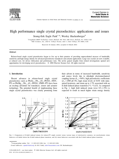
Fraunhofer-IBMT Technology Center Hialeah, 601 West 20 th Street, Hialeah, FL 33010, USA b TRS Ceramics, Inc, 2820 E. College Avenue, Suite J, State College, PA 16801, USA Received 28 January 2002; accepted 24 March 2002
* Corresponding author. Tel.: 1 1-305-925-1260; fax: 1 1-305-925-1269. E-mail addresses: epark@ (S.-E.E. Park), info@ (W. Hackenberger). 1359-0286 / 02 / $ – see front matter 2002 Elsevier Science Ltd. All rights reserved. PII: S1359-0286( 02 )00023-2
Fig. 1. Comparison of E-field induced strains for relaxor-PT single crystals versus various types of electroactive ceramics, (a) non-hysteretic strain behavior at E-fields before the E-field induced phase transition, and (b) strain behaviors associated with the E-field induced phase transition.
Current Opinion in Solid State and Materials Science 6 (2002) 11–18
机械专业毕业设计外文翻译--切削加工新概念
英文部分The new concept of cutting processingThe nowadays cutting tool company cannot only be again the manufacture and the sales cutting tool, in order to succeed, they must be consistent with the globalization manufacture tendency maintenance, through enhances the efficiency, cooperates with the customer reduces the cost. Approaches the instantaneous global competition after this after NAFTA, the WTO time, the world company is making quickly to the same feeling, is lighter, a cheaper response. In other words, they make the product and the components contain can in high speed under revolve, as a result of the cost pressure, best, is lighter moreover must make cheaply. Obtains these goals a best way is through develops and applies the new material, but these is new and the improvement material usually all with difficulty processes. In in this kind of commercial power and the technical difficulty combination is especially prominent in the automobile and the aviation industry, and has become has the experience the cutting tool company to research and develop the department the most important driving influence.For example, takes the modular cast iron to say that, it has become the engine part and other automobiles, the agriculture the material which see day by day with the equipment and in the machine tool industry components. This kind of alloy provides the low production cost and the good machine capability combination. They are cheaper than the steel products, but has a higher intensity and toughness compared to the cast iron. But at the same time the modular cast iron is extremely wear-resisting, has fast breaks by rubbing the cutting tool material the tendency. In this wear resistant very great degree bead luminous body content influence. Some known modular cast iron bead luminous body content higher, its resistance to wear better, moreover its machinability is worse. Moreover, the modular cast iron porosity causes off and on to cut, this even more reduces the life.May estimate that, the high degree of hardness and the high wear-resisting cutting material quality must consider the modular cast iron the high resistance to wear. And the material quality contains extremely hard TiC in fact (carbonized titanium) or TiCN (carbon titanium nitrides) thick coating when cutting speed each minute 300 meters processes the modular cast iron to prove usually is effective. But along with cutting speed increase, scrap/The cutting tool junction plane temperature also is increasing. When has such situation, the TiC coating favors in has the chemical reaction with the iron and softens, more pressures function in anti- crescent moon hollow attrition coating. Under these conditions, hoped has one chemical stability better coating,like Al2O3 (although under low speed was inferior to TiC hard or is wear-resisting).The chemical stability becomes an important performance performance dividing line compared to the resistance to wear the factor, the speed and the temperature is decided in is processed the modular cast iron the crystal grain structure and the performance. But usually thick coating of TiCN and TiC or only ductile iron oxides in the soil coating is applied to, because the today majority of this kinds are processed the material the cutting speed in each minute 150 to 335 meters between. Is higher than each minute 300 meter applications regarding the speed, the people to this kind of material are satisfied.In order to cause this scope performance to be most superior, the mountain high researched and developed and has promoted in view of modular cast iron processing material quality TX150. This kind of material quality has hard also the anti- distortion substrate, is very ideal regarding the processing modular cast iron. Its coating the oxide compound coating which hollowly wears by thick very wear-resisting carbon titanium nitrides and a thin anti- crescent moon, the top is thin layer TiN. This kind of coating which needs the center warm chemistry gas phase deposition using the state of the art production resistance to wear and the anti- crescent moon hollow attrition which the CVD coating complete degree of hardness moreover the tough smoothness increases (MTCVD) the craft. Substrate/The coating combination performance gives the very high anti- plastic deformation and the cutting edge micro collapses the ability, causes it to become under the normal speed to process the modular cast iron the ideal material quality.The coating ceramics also display can effectively process the modular cast iron. In the past, the aluminum oxide ceramics application which not the coating tough good such as nitriding silicon and the silicon carbide textile fiber strengthened the work piece material chemistry paralysis limit. Today but could resist the scrap distortion process through the use to have the high thermal coating cutting tool life already remarkably to increase. But certain early this domains work piece processing use aluminum oxides spread the layer crystals to have to strengthen the ceramics, today most research concentrate in the TiN coating nitriding silicon. This kind of coating can remarkably open up the tough good ceramics the application scope.When machining, the work piece has processed the surface is depends upon the cutting tool and the work piece makes the relative motion to obtain.According to the surface method of formation, the machining may divide into the knife point path law, the formed cutting tool law, the generating process three kinds.The knife point path law is depends upon the knife point to be opposite in the work piece surface path, obtains the superficial geometry shape which the work piece requests, like the turning outer annulus, the shaping plane, the grinding outer annulus, with the profile turning forming surface and so on, the knife point path are decided the cutting tool and the work piecerelative motion which provides in the engine bed;The formed cutting tool law abbreviation forming, is with the formed cutting tool which matches with the work piece final superficial outline, or the formed grinding wheel and so on processes the formed surface, like formed turning, formed milling and form grinding and so on, because forms the cutting tool the manufacture quite to be difficult, therefore only uses in processing the short formed surface generally;The generating process name rolls cuts method, is when the processing the cutting tool and the work piece do unfold the movement relatively, the cutting tool and the work piece centrode make the pure trundle mutually, between both maintains the definite transmission ratio relations, obtains the processing surface is the knife edge in this kind of movement envelope, in the gear processing rolls the tooth, the gear shaping, the shaving, the top horizontal jade piece tooth and rubs the tooth and so on to be the generating process processing.Some machining has at the same time the knife point path law and the formed cutting tool method characteristic, like thread turning.The machining quality mainly is refers to the work piece the processing precision and the surface quality (including surface roughness, residual stress and superficial hardening).Along with the technical progress, the machining quality enhances unceasingly.The 18th century later periods, the machining precision counts by the millimeter; At the beginning of 20th century, machining precision Gao Yida 0.01 millimeter; To the 50's, the machining precision has reached a micron level; The 70's, the machining precision enhances to 0.1 micron.The influence machining quality primary factor has aspects and so on engine bed, cutting tool, jig, work piece semifinished materials, technique and processing environment.Must improve the machining quality, must take the suitable measure to the above various aspects, like reduces the engine bed work error, selects the cutting tool correctly, improves the semifinished materials quality, the reasonable arrangement craft, the improvement environmental condition and so on.Enhances the cutting specifications to enhance the material excision rate, is enhances the machining efficiency the essential way.The commonly used highly effective machining method has the high-speed cutting, the force cutting, the plasma arc heating cuts and vibrates the cutting and so on.The grinding speed is called the high-speed grinding in 45 meters/second above es the high-speed cutting (or grinding) both may enhance the efficiency, and may reduce the surface roughness.The high-speed cutting (or grinding) requests the engine bed to have the high speed, the high rigidity, the high efficiency and the vibration-proof good craft system; Requests the cutting tool to have the reasonable geometry parameter and theconvenience tight way, but also must consider the safe reliable chip breaking method.The force cutting refers to the roughing feed or cuts the deep machining greatly, uses in the turning and the grinding generally.The force turning main characteristic is the lathe tool besides the main cutting edge, but also some is parallel in the work piece has processed superficial the vice-cutting edge simultaneously to participate in the cutting, therefore may enhance to feed quantity compared to the general turning several times of even several pares with the high-speed cutting, the force cutting cutting temperature is low, the cutting tool life is long, the cutting efficiency is high; The shortcoming is processes the surface to be rough.When force cutting, the radial direction cutting force death of a parent is not suitable for to process the tall and slender work piece very much.The vibration cutting is along the cutting tool direction of feed, the attachment low frequency or the high frequency vibration machining, may enhance the cutting efficiency.The low frequency vibration cutting has the very good chip breaking effect, but does not use the chip breaking equipment, makes the knife edge intensity to increase, time the cutting total power dissipation compared to has the chip breaking installment ordinary cutting to reduce about 40%.The high frequency vibration cutting also called the ultrasonic wave vibration cutting, is helpful in reduces between the cutting tool and the work piece friction, reduces the cutting temperature, reduces the cutting tool the coherence attrition, thus the enhancement cutting efficiency and the processing surface quality, the cutting tool life may enhance 40% approximately.To lumber, plastic, rubber, glass, marble, granite and so on nonmetallic material machining, although is similar with the metal material cutting, but uses the cutting tool, the equipment and the cutting specifications and so on has the characteristic respectively.The lumber product machining mainly carries in each kind of joiner's bench, its method mainly has: The saw cuts, digs cuts, the turning, the milling, drills truncates with the polishing and so on.The plastic rigidity is worse than the metal, the easy bending strain, the thermoplastic thermal conductivity to be in particular bad, easy to elevate temperature the conditioning.When cutting plastic, suitably with the high-speed steel or the hard alloy tools, selects the small to feed quantity and the high cutting speed, and uses compressed air cooling.If the cutting tool is sharp, the angle is appropriate, may produce the belt-shaped scrap, easy to carry off the quantity of heat.Glass (including semiconducting material and so on germanium, silicon) but degree of hardness high brittleness is big.To methods and so on glass machining commonly used cutting, drill hole, attrition and polishing.To thickness in three millimeters following glass plates, thesimple cutting method is with the diamond or other hard materials, in glass surface manual scoring, the use scratch place stress concentration, then uses the hand to break off.To the marble, the granite and the concrete and so on the hard material processing, mainly uses methods and so on cutting, turning, drill hole, shaping, attrition and polishing.When cutting the available circular saw blade adds the grinding compound and the water; The outer annulus and the end surface may use the negative rake the hard alloy lathe tool, by 10~30 meter/minute cutting speed turning; Drills a hole the available hard alloy drill bit; The big stone material plane available hard alloy planing tool or rolls cuts planing tool shaping; The precise smooth surface, available three mutually for the datum to the method which grinds, or the grinding and the polishing method obtains.Cutting tool in hot strong alloy applicationThe aviation processing also changes rapidly. For example, nickel base heat-resisting alloy like several years ago the most people had not heard Rene88 now occupies to the aircraft engine manufacture uses the total metal quantity 10~25%. Has very good showing and the commercial reason regarding this. For example, these heat strong alloy will be able to increase the engine endurance moreover to permit the small engine work on the big airplane, that will enhance the combustion efficiency and reduces the operation cost. These tough good materials also present the expense on the cutting tool. Their thermal stability causes on the knife point the temperature to be higher, thus reduced the cutting tool life. Similarly, in these alloy carbide pellet remarkably increased the friction, thus reduces the cutting tool life.As a result of changes in these conditions, can be very pleased to have processed many titanium alloys and nickel-based alloy materials C-2 hard metal alloys, in the application to today's cutting edge of blade to the crushing and cutting depth of the trench lines badly worn. But using the latest high-temperature processing of small particles hard metal alloys to be effective, cutlery life improved, but more importantly to enhance the reliability of applications in high-temperature alloys. Small particles hard metal than traditional hard metal materials higher compression strength and hardness, only a small increase in the resilience of the cost. And resulted in high temperature alloy processing than traditional hard metal resistance common failure mode more effective.PVD (physical gas phase deposition) coating also by certificate effective processing heat-resisting alloy. TiN (titanium nitrides) the PVD coating was uses and still was most early most receives welcome. Recently, TiAlN (nitrogen calorization titanium) and TiCN (carbon titanium nitrides) the coating also could very good use. In the past the TiAlN coating application scope and TiN compared the limit to be more. But after the cutting speed enhances them is a very good choice, enhances the productivity in these applications to reach 40%. On the other hand, isdecided under the low cutting speed in coating superficial operating mode TiAlN can cause to accumulate the filings lump afterwards, micro collapses with the trench attrition.Recently, used in the heat-resisting alloy application material quality already developing, these coating but became by several combinations. The massive laboratories and the scene test has already proven this kind of combination and other any kind of sole coating compares in time the very wide scope application is very effective. Therefore aims at the heat-resisting alloy application the PVD compound coating possibly to become the focal point which the hard alloy new material quality research and development continues. With the MTCVD coating, the coating ceramics gather in the same place, they hopefully become a more effective processing to research and develop newly are more difficult to process the work piece material the main impact strength.Dry processingIncluding the refrigerant question is technical and the commercial expansion industrial production tendency another domain which the cutting tool makes. North America and the European strict refrigerant management request and the biggest three automobile manufacturer forces them the core supplier to obtain the ISO14000 authentication (the ISO9000 environment management edition), this causes the refrigerant processing cost rise. To the car company and their core supplier said obviously one of responses which welcome is in the specific processing application avoids completely the refrigerant the use. This kind did the processing the new world to propose a series of challenges for the cutting tool supplier.Recently, already appeared some to concern this topic to promulgate the speed, to enter for, the coating chemical composition and other parameters very substantial comprehensive nature very strong useful technical papers. Wants to concentrate the elaboration in here me "does the processing viewpoint" in the operation and commercial meaning automobile manufacturer new.The metal working jobholders can the very good understanding related refrigerant use question, but majority cannot understand concerns except the technical challenge (for example row of filings) beside does the processing question in the cutting tool - work piece contact face between. Usually may observe to the refrigerant disperser scrap which flows out, but the pressure surpasses 3,000 pounds/An inch 2 high speed refrigerant also can help to break the filings, specially soft also the continual scrap can cause in the cutting tool - work piece contact face trouble.Uses does the cutting craft the components result is the engine bed uses the wet type processing components to be hotter than. Whether before you do allow them to survey in the open-air natural cooling? If processes newly the hot components put frequently to the turnover box, elevates the environment temperature, whether components full cooling and just rightenough permission precision examination? Also has the handling side several dozens on hundred components to be able to operate the worker to increase the extra burden.With many cutting tools/The work piece technical question same place, these latent questions need to state whether dryly adds the ability line. Luckily, has very many ways to elaborate these questions. For example, the compressed air was proven row of filings becomes the question in very many applications the situation to have the successful echo.Another plan is called MQL (minimum lubrication) a technology, it replaces the traditional refrigerant by the application the quite few oil mists constitution. This is a recognition compromise plan, this kind of minimum technology can large scale reduce the refrigerant the headache matter, moreover the smooth finish which processes in many applications very is also good. This domain still had very many research to do, moreover the cutting tool company positively participated in such research was absolutely essential. If they will not do fall behind the competitor, will be at the disadvantageous position.In the factory the special details design other perhaps better plan according to the world in. The manufacturing industry jobholders possibly still could ask why they do have to use recent development the technology to replace the refrigerant method diligently which the tradition already an experience number generation of person improved enhances, because implemented especially does the experiment and the defeat which the processing or the subarid processing produced possibly causes the higher short-term cutting tool cost. The concise answer is when the bit probably accounts for the model processing components cost 3%, the refrigerant cost (from purchases to maintenance, storage, processing) can account for the components cost 15%.Perhaps does the dry processing is not all suits to each application, but above discusses likely other processing questions are same, needs from a wider operation, the environment and the commercial angle appraises. Will be able to help the cutting tool company which the customer will do this to have the competitive advantage, but these will not be able to provide unceasingly is in the passive position.Cutting tool and nanotechnologyCan fiercely change the cutting tool industry the enchanting new domain is the miniature manufacture, or the processing small granule forms the product which needs. Must refer to is its here does not have about the cutting tool miniature manufacture first matter; Second must say the matter is it is not remote.Why the miniature manufacture and are the cutting tool related. Because most main is the particle size smaller, the hard alloy toughness of material better also is more wear-resisting. (Some experts define with the nanometer level pellet for are smaller than 0.2 mu m, but other people persisted a nanometer pellet had to be smaller than the hard alloy tools prototype which0.1 mu m) made already to complete and the test,It is said that wear resistant theatrically increase. The question is the nanometer level hard alloy pellet cannot depend on the smashing big material formation, they are certain through the smaller material constitution, but processes the molecular level granule is not easy and the economical matter.中文部分切削加工新概念现今的刀具公司再也不能只是制造和销售刀具,为了成功,他们必须与全球化制造趋势保持一致,通过提高效率、同客户合作来降低成本。
机械设计制造及其自动化毕业论文中英文资料外文翻译

机械设计创造及其自动化毕业论文外文文献翻译INTEGRATION OF MACHINERY译文题目专业机械设计创造及其自动化外文资料翻译INTEGRATION OF MACHINERY(From ELECTRICAL AND MACHINERY INDUSTRY)ABSTRACTMachinery was the modern science and technology development inevitable result, this article has summarized the integration of machinery technology basic outline and the development background .Summarized the domestic and foreign integration of machinery technology present situation, has analyzed the integration of machinery technology trend of development.Key word: integration of machinery ,technology, present situation ,product t,echnique of manufacture ,trend of development0. Introduction modern science and technology unceasing development, impelled different discipline intersecting enormously with the seepage, has caused the project domain technological revolution and the transformation .In mechanical engineering domain, because the microelectronic technology and the computer technology rapid development and forms to the mechanical industry seepage the integration of machinery, caused the mechanical industry the technical structure, the product organization, the function and the constitution, the production method and the management systemof by machinery for the characteristic integration ofdevelopment phase.1. Integration of machinery outline integration of machinery is refers in the organization new owner function, the power function, in the information processing function and the control function introduces the electronic technology, unifies the system the mechanism and the computerization design and the software which constitutes always to call. The integration of machinery development also has become one to have until now own system new discipline, not only develops along with the science and technology, but also entrusts with the new content .But its basic characteristic may summarize is: The integration of machinery is embarks from the system viewpoint, synthesis community technologies and so on utilization mechanical technology, microelectronic technology, automatic control technology, computer technology, information technology, sensing observation and control technology, electric power electronic technology, connection technology, information conversion technology as well as software programming technology, according to the system function goal and the optimized organization goal, reasonable disposition and the layout various functions unit, in multi-purpose, high grade, redundant reliable, in the low energy consumption significance realize the specific function value, and causes the overall system optimization the systems engineering technology .From this produces functional system, then becomes an integration of machinery systematic or the integration of machinery product. Therefore, of coveringtechnology is based on the above community technology organic fusion one kind of comprehensive technology, but is not mechanical technical, the microelectronic technology as well as other new technical simple combination, pieces together .This is the integration of machinery and the machinery adds the machinery electrification which the electricity forms in the concept basic difference .The mechanical engineering technology has the merely technical to develop the machinery electrification, still was the traditional machinery, its main function still was replaces with the enlargement physical strength .But after develops the integration of machinery, micro electron installment besides may substitute for certain mechanical parts the original function, but also can entrust with many new functions,like the automatic detection, the automatic reduction information, demonstrate the record, the automatic control and the control automatic diagnosis and the protection automatically and so on .Not only namely the integration of machinery product is human's hand and body extending, human's sense organ and the brains look, has the intellectualized characteristic is the integration of machinery and the machinery electrification distinguishes in the function essence.2. Integration of machinery development condition integration of machinery development may divide into 3 stages roughly.20th century 60's before for the first stage, this stage is called the initial stage .In this time, the people determination not on own initiative uses the electronic technology the preliminary achievement to consummate the mechanical product the performance .Specially in Second World War period, the war has stimulated the mechanical product and the electronic technology union, these mechanical and electrical union military technology, postwar transfers civilly, to postwar economical restoration positive function .Developed and the development at that time generally speaking also is at the spontaneouscondition .Because at that time the electronic technology development not yet achieved certain level, mechanical technical and electronic technology union also not impossible widespread and thorough development, already developed the product was also unable to promote massively. The 20th century 70~80 ages for the second stage, may be called the vigorous development stage .This time, the computer technology, the control technology, the communication development, has laid the technology base for the integration of machinery development . Large-scale, ultra large scale integrated circuit and microcomputer swift and violent development, has provided the full material base for the integration of machinery development .This time characteristic is :①A mechatronics word first generally is accepted in Japan, probably obtains the quite widespread acknowledgment to 1980s last stages in the worldwide scale ;②The integration of machinery technology and the product obtained the enormous development ;③The various countries start to the integration of machinery technology and the product give the very big attention and the support. 1990s later periods, started the integration of machinery technology the new stagewhich makes great strides forward to the intellectualized direction, the integration of machinery enters the thorough development time .At the same time, optics, the communication and so on entered the integration of machinery, processes the technology also zhan to appear tiny in the integration of machinery the foot, appeared the light integration of machinery and the micro integration of machinery and so on the new branch; On the other hand to the integration of machinery system modeling design, the analysis and the integrated method, the integration of machinery discipline system and the trend of development has all conducted the thorough research .At the same time, because the hugeprogress which domains and so on artificial intelligence technology, neural network technology and optical fiber technology obtain, opened the development vast world for the integration of machinery technology .These research, will urge the integration of machinery further to establish the integrity the foundation and forms the integrity gradually the scientific system. Our country is only then starts from the beginning of 1980s in this aspect to study with the application .The State Councilsummary had considered fully on international the influence which and possibly brought from this about the integration of machinery technology developmenttrend .Many universities, colleges and institutes, the development facility and some large and middle scale enterprises have done the massive work to this technical development and the application, does not yield certain result, but and so on the advanced countries compared with Japan still has the suitable disparity.3. Integration of machinery trend of development integrations of machinery are the collection machinery, the electron, optics, the control, the computer, the information and so on the multi-disciplinary overlapping syntheses, its development and the progress rely on and promote the correlation technology development and the progress .Therefore, the integration of machinery main development direction is as follows:3.1 Intellectualized intellectualizations are 21st century integration of machinery technological development important development directions .Theartificial intelligence obtains day by day in the integration of machinery constructor's research takes, the robot and the numerical control engine bedis to the machine behavior description, is in the control theory foundation, the absorption artificial intelligence, the operations research, the computer science, the fuzzy mathematics, the psychology, the physiology and the chaos dynamics and so on the new thought, the new method, simulate the human intelligence, enable it to have abilities and so on judgment inference, logical thinking, independent decision-making, obtains the higher control goal in order to .Indeed, enable the integration of machinery product to have with the human identical intelligence, is not impossible, also is nonessential .But, the high performance, the high speed microprocessor enable the integration of machinery product to have preliminary intelligent or human's partial intelligences, then is completely possible and essential.In the modern manufacture process, the information has become the control manufacture industry the determining factor, moreover is the most active actuation factor .Enhances the manufacture system information-handling capacity to become the modern manufacture science development a key point .As a result of the manufacture system information organization and structure multi-level, makes the information the gain, the integration and the fusion presents draws up the character, information measure multi-dimensional, as well as information organization's multi-level .In the manufacture information structural model, manufacture information uniform restraint, dissemination processing and magnanimous data aspects and so on manufacture knowledge library management, all also wait for further break through.Each kind of artificial intelligence tool and the computation intelligence method promoted the manufacture intelligence development in the manufacture widespread application .A kind based on the biological evolution algorithm computation intelligent agent, in includes thescheduling problem in the combination optimization solution area of technology, receives the more and more universal attention, hopefully completes the combination optimization question when the manufacture the solution speed and the solution precision aspect breaks through the question scale in pairs the restriction .The manufacture intelligence also displays in: The intelligent dispatch, the intelligent design, the intelligent processing, the robot study, the intelligent control, the intelligent craft plan, the intelligent diagnosis and so on are various These question key breakthrough, may form the product innovation the basic research system. Between 2 modern mechanical engineering front science different science overlapping fusion will have the new science accumulation, the economical development and society's progress has had the new request and the expectation to the science and technology, thus will form the front science .The front science also has solved and between the solution scientific question border area .The front science has the obvious time domain, the domain and the dynamic characteristic .The project front science distinguished in the general basic science important characteristic is it has covered the key science and technology question which the project actual appeared.Manufacture system is a complex large-scale system, for satisfies the manufacture system agility, the fast response and fast reorganization ability, must profit from the information science, the life sciences and the social sciences and so on the multi-disciplinary research results, the exploration manufacture system new architecture, the manufacture pattern and the manufacture system effective operational mechanism .Makes the system optimization the organizational structure and the good movement condition is makes the system modeling , the simulation and the optimized essential target .Not only the manufacture system new architecture to makes the enterprise the agility and may reorganize ability to the demand response ability to have the vital significance, moreover to made the enterprise first floor production equipment the flexibility and may dynamic reorganization ability set a higher request .The biological manufacture view more and more many is introduced the manufacture system, satisfies the manufacture system new request.The study organizes and circulates method and technique of complicated system from the biological phenomenon, is a valid exit which will solve many hard nut to cracks that manufacturing industry face from now on currently .Imitating to living what manufacturing point is mimicry living creature organ of from the organization, from match more, from growth with from evolution etc. function structure and circulate mode of a kind of manufacturing system and manufacturing process.The manufacturing drives in the mechanism under, continuously by one's own perfect raise on organizing structure and circulating mode and thus to adapt the process of[with] ability for the environment .For from descend but the last product proceed together a design and make a craft rules the auto of the distance born, produce system of dynamic state reorganization and product and manufacturing the system tend automatically excellent provided theories foundation and carry out acondition .Imitate to living a manufacturing to belong to manufacturing science and life science of"the far good luck is miscellaneous to hand over", it will produce to the manufacturing industry for 21 centuries huge of influence .机电一体化摘要机电一体化是现代科学技术发展的必然结果,本文简述了机电一体化技术的基本概要和发展背景。
机械专业毕业设计外文翻译--选择最佳工具,几何形状和切削条件

附录附录1:英文原文Selection of optimum tool geometry and cutting conditionsusing a surface roughness prediction model for end milling Abstract Influence of tool geometry on the quality of surface produced is well known and hence any attempt to assess the performance of end milling should include the tool geometry. In the present work, experimental studies have been conducted to see the effect of tool geometry (radial rake angle and nose radius) and cutting conditions (cutting speed and feed rate) on the machining performance during end milling of medium carbon steel. The first and second order mathematical models, in terms of machining parameters, were developed for surface roughness prediction using response surface methodology (RSM) on the basis of experimental results. The model selected for optimization has been validated with the Chi square test. The significance of these parameters on surface roughness has been established with analysis of variance. An attempt has also been made to optimize the surface roughness prediction model using genetic algorithms (GA). The GA program gives minimum values of surface roughness and their respective optimal conditions.1 IntroductionEnd milling is one of the most commonly used metal removal operations in industry because of its ability to remove material faster giving reasonably good surface quality. It is used in a variety of manufacturing industries including aerospace and automotive sectors, where quality is an important factor in the production of slots, pockets, precision moulds and dies. Greater attention is given to dimensional accuracy and surface roughness of products by the industry these days. Moreover, surface finish influences mechanical properties such as fatigue behaviour, wear, corrosion, lubrication and electrical conductivity. Thus, measuring and characterizing surface finish can be considered for predicting machining performance.Surface finish resulting from turning operations has traditionally received considerable research attention, where as that of machining processes using multipoint cutters, requires attention by researchers. As these processes involve large number of parameters, it would be difficult to correlate surface finish with other parameters just by conducting experiments. Modelling helps to understand this kind of process better. Though some amount of work has been carried out to develop surface finish prediction models in the past, the effect of tool geometry has received little attention. However, the radial rake angle has a major affect on the powerconsumption apart from tangential and radial forces. It also influences chip curling and modifies chip flow direction. In addition to this, researchers [1] have also observed that the nose radius plays a significant role in affecting the surface finish. Therefore the development of a good model should involve the radial rake angle and nose radius along with other relevant factors.Establishment of efficient machining parameters has been a problem that has confronted manufacturing industries for nearly a century, and is still the subject of many studies. Obtaining optimum machining parameters is of great concern in manufacturing industries, where the economy of machining operation plays a key role in the competitive market. In material removal processes, an improper selection of cutting conditions cause surfaces with high roughness and dimensional errors, and it is even possible that dynamic phenomena due to auto excited vibrations may set in [2]. In view of the significant role that the milling operation plays in today‟s manufacturing world, there is a need to optimize the machining parameters for this operation. So, an effort has been made in this paper to see the influence of tool geometry(radial rake angle and nose radius) and cutting conditions(cutting speed and feed rate) on the surface finish produced during end milling of medium carbon steel. The experimental results of this work will be used to relate cutting speed, feed rate, radial rake angle and nose radius with the machining response i.e. surface roughness by modelling. The mathematical models thus developed are further utilized to find the optimum process parameters using genetic algorithms.2 ReviewProcess modelling and optimization are two important issues in manufacturing. The manufacturing processes are characterized by a multiplicity of dynamically interacting process variables. Surface finish has been an important factor of machining in predicting performance of any machining operation. In order to develop and optimize a surface roughness model, it is essential to understand the current status of work in this area.Davis et al. [3] have investigated the cutting performance of five end mills having various helix angles. Cutting tests were performed on aluminium alloy L 65 for three milling processes (face, slot and side), in which cutting force, surface roughness and concavity of a machined plane surface were measured. The central composite design was used to decide on the number of experiments to be conducted. The cutting performance of the end mills was assessed using variance analysis. The affects of spindle speed, depth of cut and feed rate on the cutting force and surface roughness were studied. The investigation showed that end mills with left hand helix angles are generally less cost effective than those with right hand helix angles. There is no significant difference between up milling and down milling with regard tothe cutting force, although the difference between them regarding the surface roughness was large. Bayoumi et al. [4]have studied the affect of the tool rotation angle, feed rate and cutting speed on the mechanistic process parameters (pressure, friction parameter) for end milling operation with three commercially available workpiece materials, 11 L 17 free machining steel, 62- 35-3 free machining brass and 2024 aluminium using a single fluted HSS milling cutter. It has been found that pressure and friction act on the chip – tool interface decrease with the increase of feed rate and with the decrease of the flow angle, while the cutting speed has a negligible effect on some of the material dependent parameters. Process parameters are summarized into empirical equations as functions of feed rate and tool rotation angle for each work material. However, researchers have not taken into account the effects of cutting conditions and tool geometry simultaneously; besides these studies have not considered the optimization of the cutting process.As end milling is a process which involves a large number f parameters, combined influence of the significant parameters an only be obtained by modelling. Mansour and Abdallaet al. [5] have developed a surface roughness model for the end milling of EN32M (a semi-free cutting carbon case hardening steel with improved merchantability). The mathematical model has been developed in terms of cutting speed, feed rate and axial depth of cut. The affect of these parameters on the surface roughness has been carried out using response surface methodology (RSM). A first order equation covering the speed range of 30–35 m/min and a second order equation covering the speed range of 24–38 m/min were developed under dry machining conditions. Alauddin et al. [6] developed a surface roughness model using RSM for the end milling of 190 BHN steel. First and second order models were constructed along with contour graphs for the selection of the proper combination of cutting speed and feed to increase the metal removal rate without sacrificing surface quality. Hasmi et al. [7] also used the RSM model for assessing the influence of the workpiece material on the surface roughness of the machined surfaces. The model was developed for milling operation by conducting experiments on steel specimens. The expression shows, the relationship between the surface roughness and the various parameters; namely, the cutting speed, feed and depth of cut. The above models have not considered the affect of tool geometry on surface roughness.Since the turn of the century quite a large number of attempts have been made to find optimum values of machining parameters. Uses of many methods have been reported in the literature to solve optimization problems for machining parameters. Jain and Jain [8] have used neural networks for modeling and optimizing the machining conditions. The results have been validated by comparing the optimized machining conditions obtained using genetic algorithms. Suresh et al. [9] have developed a surface roughness prediction model for turning mild steel using a response surface methodology to produce the factor affects of the individual process parameters. They have also optimized the turning process using the surface roughness prediction model as theobjective function. Considering the above, an attempt has been made in this work to develop a surface roughness model with tool geometry and cutting conditions on the basis of experimental results and then optimize it for the selection of these parameters within the given constraints in the end milling operation.3 MethodologyIn this work, mathematical models have been developed using experimental results with the help of response surface methodolog y. The purpose of developing mathematical models relating the machining responses and their factors is to facilitate the optimization of the machining process. This mathematical model has been used as an objective function and the optimization was carried out with the help of genetic algorithms.3.1 Mathematical formulationResponse surface methodology(RSM) is a combination of mathematical and statistical techniques useful for modelling and analyzing the problems in which several independent variables influence a dependent variable or response. The mathematical models commonly used are represented by:where Y is the machining response, ϕ is the response function and S, f , α, r are milling variables and ∈ is the error which is normally distributed about the observed response Y with zero mean.The relationship between surface roughness and other independent variables can be represented as follows,where C is a constant and a, b, c and d are exponents.To facilitate the determination of constants and exponents, this mathematical model will have to be linearized by performing a logarithmic transformation as follows:The constants and exponents C, a, b, c and d can be determined by the method of least squares. The first order linear model, developed from the above functional relationship using least squares method, can be represented as follows:where Y1 is the estimated response based on the first-order equation, Y is the measured surface roughness on a logarithmic scale, x0 = 1 (dummy variable), x1, x2, x3 and x4 are logarithmic transformations of cutting speed, feed rate, radial rake angle and nose radius respectively, ∈is the experimental error and b values are the estimates of corresponding parameters.The general second order polynomial response is as given below:where Y2 is the estimated response based on the second order equation. The parameters, i.e. b0, b1, b2, b3, b4, b12, b23, b14, etc. are to be estimated by the method of least squares. Validity ofthe selected model used for optimizing the process parameters has been tested with the help of statistical tests, such as F-test, chi square test, etc. [10].3.2 Optimization using genetic algorithmsMost of the researchers have used traditional optimization techniques for solving machining problems. The traditional methods of optimization and search do not fare well over a broad spectrum of problem domains. Traditional techniques are not efficient when the practical search space is too large. These algorithms are not robust. They are inclined to obtain a local optimal solution. Numerous constraints and number of passes make the machining optimization problem more complicated. So, it was decided to employ genetic algorithms as an optimization technique. GA come under the class of non-traditional search and optimization techniques. GA are different from traditional optimization techniques in the following ways:1.GA work with a coding of the parameter set, not the parameter themselves.2.GA search from a population of points and not a single point.3.GA use information of fitness function, not derivatives or other auxiliary knowledge.4.GA use probabilistic transition rules not deterministic rules.5.It is very likely that the expected GA solution will be the global solution.Genetic algorithms (GA) form a class of adaptive heuristics based on principles derived from the dynamics of natural population genetics. The searching process simulates the natural evaluation of biological creatures and turns out to be an intelligent exploitation of a random search. The mechanics of a GA is simple, involving copying of binary strings. Simplicity of operation and computational efficiency are the two main attractions of the genetic algorithmic approach. The computations are carried out in three stages to get a result in one generation or iteration. The three stages are reproduction, crossover and mutation.In order to use GA to solve any problem, the variable is typically encoded into a string (binary coding) or chromosome structure which represents a possible solution to the given problem. GA begin with a population of strings (individuals) created at random. The fitness of each individual string is evaluated with respect to the given objective function. Then this initial population is operated on by three main operators – reproduction cross over and mutation– to create, hopefully, a better population. Highly fit individuals or solutions are given the opportunity to reproduce by exchanging pieces of their genetic information, in the crossover procedure, with other highly fit individuals. This produces new “offspring” solutions, which share some characteristics taken from both the parents. Mutation is often applied after crossover by altering some genes (i.e. bits) in the offspring. The offspring can either replace the whole population (generational approach) or replace less fit individuals (steady state approach). This new population is further evaluated andtested for some termination criteria. The reproduction-cross over mutation- evaluation cycle is repeated until the termination criteria are met.4 Experimental detailsFor developing models on the basis of experimental data, careful planning of experimentation is essential. The factors considered for experimentation and analysis were cutting speed, feed rate, radial rake angle and nose radius.4.1 Experimental designThe design of experimentation has a major affect on the number of experiments needed. Therefore it is essential to have a well designed set of experiments. The range of values of each factor was set at three different levels, namely low, medium and high as shown in Table 1. Based on this, a total number of 81 experiments (full factorial design), each having a combination of different levels of factors, as shown in Table 2, were carried out.The variables were coded by taking into account the capacity and limiting cutting conditions of the milling machine. The coded values of variables, to be used in Eqs. 3 and 4, were obtained from the following transforming equations:where x1 is the coded value of cutting speed (S), x2 is the coded value of the feed rate ( f ), x3 is the coded value of radial rake angle(α) and x4 is the coded value of nose radius (r).4.2 ExperimentationA high precision …Rambaudi Rammatic 500‟ CNC milling machine, with a vertical milling head, was used for experimentation. The control system is a CNC FIDIA-12 compact. The cutting tools, used for the experimentation, were solid coated carbide end mill cutters of different radial rake angles and nose radii (WIDIA: DIA20 X FL38 X OAL 102 MM). The tools are coated with TiAlN coating. The hardness, density and transverse rupture strength are 1570 HV 30, 14.5 gm/cm3 and 3800 N/mm2 respectively.AISI 1045 steel specimens of 100×75 mm and 20 mm thickness were used in the present study. All the specimens were annealed, by holding them at 850 ◦C for one hour and then cooling them in a furnace. The chemical analysis of specimens is presented in Table 3. The hardness of the workpiece material is 170 BHN. All the experiments were carried out at a constant axial depth of cut of 20 mm and a radial depth of cut of 1 mm. The surface roughness (response) was measured with Talysurf-6 at a 0.8 mm cut-off value. An average of four measurements was used as a response value.5 Results and discussionThe influences of cutting speed, feed rate, radial rake angle and nose radius have been assessed by conducting experiments. The variation of machining response with respect to the variables was shown graphically in Fig. 1. It is seen from these figures that of the four dependent parameters, radial rake angle has definite influence on the roughness of the surface machined using an end mill cutter. It is felt that the prominent influence of radial rake angle on the surface generation could be due to the fact that any change in the radial rake angle changes the sharpness of the cutting edge on the periphery, i.e changes the contact length between the chip and workpiece surface. Also it is evident from the plots that as the radial rake angle changes from 4◦to 16◦, the surface roughness decreases and then increases. Therefore, it may be concluded here that the radial rake angle in the range of 4◦to 10◦would give a better surface finish. Figure 1 also shows that the surface roughness decreases first and then increases with the increase in the nose radius. This shows that there is a scope for finding the optimum value of the radial rake angle and nose radius for obtaining the best possible quality of the surface. It was also found that the surface roughness decreases with an increase in cutting speed and increases as feed rate increases. It could also be observed that the surface roughness was a minimum at the 250 m/min speed, 200 mm/min feed rate, 10◦radial rake angle and 0.8 mm nose radius. In order to understand the process better, the experimental results can be used to develop mathematical models using RSM. In this work, a commercially available mathematical software package (MATLAB) was used for the computation of the regression of constants and exponents.5.1 The roughness modelUsing experimental results, empirical equations have been obtained to estimate surface roughness with the significant parameters considered for the experimentation i.e. cutting speed, feed rate, radial rake angle and nose radius. The first order model obtained from the above functional relationship using the RSM method is as follows:The transformed equation of surface roughness prediction is as follows:Equation 10 is derived from Eq. 9 by substituting the coded values of x1, x2, x3 and x4 in terms of ln s, ln f , lnαand ln r. The analysis of the variance (ANOVA) and the F-ratio test have been performed to justify the accuracy of the fit for the mathematical model. Since the calculated values of the F-ratio are less than the standard values of the F-ratio for surface roughness as shown in Table 4, the model is adequate at 99% confidence level to represent the relationship between the machining response and the considered machining parameters of the end milling process.The multiple regression coefficient of the first order model was found to be 0.5839. This shows that the first order model can explain the variation in surface roughness to the extent of58.39%. As the first order model has low predictability, the second order model has been developed to see whether it can represent better or not.The second order surface roughness model thus developed is as given below:where Y2 is the estimated response of the surface roughness on a logarithmic scale, x1, x2, x3 and x4 are the logarithmic transformation of speed, feed, radial rake angle and nose radius. The data of analysis of variance for the second order surface roughness model is shown in Table 5.Since F cal is greater than F0.01, there is a definite relationship between the response variable and independent variable at 99% confidence level. The multiple regression coefficient of the second order model was found to be 0.9596. On the basis of the multiple regression coefficient (R2), it can be concluded that the second order model was adequate to represent this process. Hence the second order model was considered as an objective function for optimization using genetic algorithms. This second order model was also validated using the chi square test. The calculated chi square value of the model was 0.1493 and them tabulated value at χ2 0.005 is 52.34, as shown in Table 6, which indicates that 99.5% of the variability in surface roughness was explained by this model.Using the second order model, the surface roughness of the components produced by end milling can be estimated with reasonable accuracy. This model would be optimized using genetic algorithms (GA).5.2 The optimization of end millingOptimization of machining parameters not only increases the utility for machining economics, but also the product quality toa great extent. In this context an effort has been made to estimate the optimum tool geometry and machining conditions to produce the best possible surface quality within the constraints.The constrained optimization problem is stated as follows: Minimize Ra using the model given here:where xil and xiu are the upper and lower bounds of process variables xi and x1, x2, x3, x4 are logarithmic transformation of cutting speed, feed, radial rake angle and nose radius.The GA code was developed using MATLAB. This approach makes a binary coding system to represent the variables cutting speed (S), feed rate ( f ), radial rake angle (α) and nose radius (r), i.e. each of these variables is represented by a ten bit binary equivalent, limiting the total string length to 40. It is known as a chromosome. The variables are represented as genes (substrings) in the chromosome. The randomly generated 20 such chromosomes (population size is 20), fulfillingthe constraints on the variables, are taken in each generation. The first generation is called the initial population. Once the coding of the variables has been done, then the actual decoded values for the variables are estimated using the following formula:where xi is the actual decoded value of the cutting speed, feed rate, radial rake angle and nose radius, x(L) i is the lower limit and x(U) i is the upper limit and li is the substring length, which is equal to ten in this case.Using the present generation of 20 chromosomes, fitness values are calculated by the following transformation:where f(x) is the fitness function and Ra is the objective function.Out of these 20 fitness values, four are chosen using the roulette-wheel selection scheme. The chromosomes corresponding to these four fitness values are taken as parents. Then the crossover and mutation reproduction methods are applied to generate 20 new chromosomes for the next generation. This processof generating the new population from the old population is called one generation. Many such generations are run till the maximum number of generations is met or the average of four selected fitness values in each generation becomes steady. This ensures that the optimization of all the variables (cutting speed, feed rate, radial rake angle and nose radius) is carried out simultaneously. The final statistics are displayed at the end of all iterations. In order to optimize the present problem using GA, the following parameters have been selected to obtain the best possible solution with the least computational effort:Table 7 shows some of the minimum values of the surface roughness predicted by the GA program with respect to input machining ranges, and Table 8 shows the optimum machining conditions for the corresponding minimum values of the surface roughness shown in Table 7. The MRR given in Table 8 was calculated bywhere f is the table feed (mm/min), aa is the axial depth of cut (20 mm) and ar is the radial depth of cut (1 mm).It can be concluded from the optimization results of the GA program that it is possible to select a combination of cutting speed, feed rate, radial rake angle and nose radius for achieving the best possible surface finish giving a reasonably good material removal rate. This GA program provides optimum machining conditions for the corresponding given minimum values of the surface roughness. The application of the genetic algorithmic approach to obtain optimal machining conditions will be quite useful at the computer aided process planning (CAPP) stage in the production of high quality goods with tight tolerances by a variety of machining operations, and in the adaptive control of automated machine tools. With the known boundaries of surface roughness and machining conditions, machining could be performed with a relatively high rate of success with the selected machining conditions.6 ConclusionsThe investigations of this study indicate that the parameters cutting speed, feed, radial rake angle and nose radius are the primary actors influencing the surface roughness of medium carbon steel uring end milling. The approach presented in this paper provides n impetus to develop analytical models, based on experimental results for obtaining a surface roughness model using the response surface methodology. By incorporating the cutter geometry in the model, the validity of the model has been enhanced. The optimization of this model using genetic algorithms has resulted in a fairly useful method of obtaining machining parameters in order to obtain the best possible surface quality.中文翻译选择最佳工具,几何形状和切削条件利用表面粗糙度预测模型端铣摘要:刀具几何形状对工件表面质量产生的影响是人所共知的,因此,任何成型面端铣设计应包括刀具的几何形状。
机械专业毕业设计--外文资料和翻译

Metal heat treatmentA, annealingIn front of the description lengba processing materials and softening plastic treatment methods, it has been used the word, the word annealing with similar meanings. The purpose is to reduce completely annealing, hardness, plastic, sometimes also increased to improve the cutting performance, high this steel is difficult to processing. This method is used to reduce heat stress, refined grains, improve the structure of the material.Annealing is not always can improve the cutting machining, cutting processing a word used to describe several factors, including material cutting when good finish (i.e. smaller surface roughness - the ability of the translator. When fully annealing, ordinary low hardness, low intensity of cutting resistance smaller, less, but usually due to the plasticity and toughness is too big to chip away when the surface of workpiece surface of workpiece surface quality, scratch, leads to poor cutting processing. For this kind of steel, annealing may not be the most appropriate treatment. Many of the most high and cutting steel processing usually can be greatly improved by annealing except in the soft, because of their condition, high hardness and strength for processing.And the annealing method is GongXi just slow to the steel wire, insulation above about for a period of time, make the same temperature uniformity, forming materials, then the austenitic or buried with furnace lime or other insulating materials in slow cooling. To precipitation of ferrite and pearlite bulky iron, steel in the soft, the strain of toughness and minimum, must slow cooling.Second, normalizingHow much is the fire of similar purposes, but not the annealing steel soft and fine pearlite state. Not bulky. Steel is refined grains, fire can release of stress, improve structural homogeneity and restore some plastic, high toughness. This method is often used to improve cutting machining, reduce stress, reduce part machining or limitation of deformation.Is the fire will chromatography method is GuoGongXiGang steel or slow heatedto Ac3 respectively, Accm line or on-line insulation for a period of time to form, and in the austenitic stationary air slow cooling. Should notice more, GongXi composition of carbon steel needs to be heated to Accm line above, not Ac1 line above the annealing. The purpose is in the process of austenitic to dissolve all cementite, thus to minimize the boundaries on hard and brittle iron carbon compounds, and get little grain of ferrite pearlite, minimum free cementite and freedom.Third, the ball annealingThrough the steel ball annealing can get minimum hardness and the biggest plastic, it can make the iron carbon compounds with small globular distribution in ferritic matrix. In order to make the ball easier small particles, usually for fire steel ball annealing. Ball annealing available in several different methods, but all the methods are needed in A1 line near (usually slightly low temperature preservation) for a long time, make the iron carbon compounds formed more stable, low level of small ball.Ball annealing method of the main objective is to improve the cutting processing, and drawing of hardened steel pretreatment, make it more uniform structure quenching. Because of the heat treatment for a long time, so the cost is higher than that of ball annealing is common or annealing.Four, steel sclerosisThe most hardened steel heat treatment method is based on the production of martensite high. Therefore, the first step to most other treatment with commonly used method -- austenitic. YaGongXiGang heated to Ac1 liquidus temperature, heat preservation, more about that temperature uniformly, austenitic evenly. GuoGongXiGang Ac1 above liquidus temperature preservation in steel, while about still remain iron carbon compounds.The second step is to avoid rapid cooling in the nose produces isothermal curve transformation pearlite. The cooling speed depends on the temperature and hardened steel quenching medium heat can be taken away from the surface of the ability of heat transfer and steel itself. Table 1-11 is some common medium and cooling method, cooling ability of the sequence.High temperature gradient produces high stress, deformation and cracking causes,so only in the very need to produce quenching specific structures are used. When the quenching heat uniform, care must be taken to reduce the heat stress diffusion. For example, a thin stick to end its vertical quenching, is inserted into the cooling medium, so whole section and temperature changes. If the shape of a side of the workpiece cooling, and on the other side of the earlier than size change is likely to cause high stress, produce plastic flow and permanent deformation.With several special quenching method can reduce stress, deformation and cracking quenching decreases. One called hierarchical quenching, the method is: will the austenitic steel in temperature is higher than that of martensite transformation temperature (Ms), salt bath time until the temperature uniformity, at the beginning of forming bainite, then put before air cooling, heat generated from the start when the same hardware quenching cracking, martensite and warpage cause of high thermal stress or eliminate stress have been quenched.In a similar method of temperature, then, is called the isothermal quenching (austenitic steel in salt bath), keep for a long time, the result is formed with the isothermal bainite. Bainite structure in the same ingredients as the formation of martensite hard, but in normal hardened steel, reduce the heat shock, by further processing, unnecessary in high hardness can be obtained when good impact toughness.Five, temperingTo adjust hardened steel used the third step is often backfire. Besides the isothermal quenching steel quenching condition usually used in most all can use in production. To produce martensite steel to quench make hard, macro and micro stress, stress, low plasticity materials. To reduce the harm that can be heated to steel again by low-temperature shift (A1) below a certain temperature. Hardened steel structure change of tempering time and temperature is the function of temperature, which is the most important. Must be hardened piece.it is emphasized, method, but the reverse is true. Steel is tempered by heat treatment of hardened steel, through the tempering of heating, to release stress again, soften and improve plastic.The structural change and tempering causes change depending on performance of the heating temperature steel back. The higher the temperature, the temperatureeffect, so the choice is often sacrificed for the hardness and strength plasticity and toughness. Again, to quench heating to influence of carbon-steel, in between, structure, changes will occur in the above, the structure and properties of the significant changes. In the next time the temperature of the A1 heat will produce and process of ball annealing of similar structures.In industry, usually avoid to scope, because the tempering within the scope of tempering steel often produced unexplained brittleness or plastic loss. Some alloy in to scope, also can produce "temper brittleness, especially from" (or by) the temperature range slow cooling will appear. When these steel heat temper, they must usually heated to rapid cooling and above. Of course, from the temperature of cold won't produce sclerosis, fast because no austenitic.金属热处理一、退火在前面描述冷拔加工材料的软化并重新获得塑性的热处理方法时,就已使用退火这个词,该词具有相似的意义。
20外文文献翻译原文及译文参考样式

20外⽂⽂献翻译原⽂及译⽂参考样式华北电⼒⼤学科技学院毕业设计(论⽂)附件外⽂⽂献翻译学号: 0819******** 姓名:宗鹏程所在系别:机械⼯程及⾃动化专业班级:机械08K1指导教师:张超原⽂标题:Development of a High-PerformanceMagnetic Gear年⽉⽇⾼性能磁齿轮的发展1摘要:本⽂提出了⼀个⾼性能永磁齿轮的计算和测量结果。
上述分析的永磁齿轮有5.5的传动⽐,并能够提供27 Nm的⼒矩。
分析表明,由于它的弹簧扭转常数很⼩,因此需要特别重视安装了这种⾼性能永磁齿轮的系统。
上述分析的齿轮也已经被应⽤在实际中,以验证、预测其效率。
经测量,由于较⼤端齿轮传动引起的磁⼒齿轮的扭矩只有16 Nm。
⼀项关于磁齿轮效率损失的系统研究也展⽰了为什么实际⼯作效率只有81%。
⼀⼤部分磁损耗起源于轴承,因为机械故障的存在,此轴承的备⽤轴承在此时是必要的。
如果没有源于轴的少量磁泄漏,我们估计能得到⾼达96%的效率。
与传统的机械齿轮的⽐较表明,磁性齿轮具有更好的效率和单位体积较⼤扭矩。
最后,可以得出结论,本⽂的研究结果可能有助于促进传统机械齿轮向磁性齿轮发展。
关键词:有限元分析(FEA)、变速箱,⾼转矩密度,磁性齿轮。
⼀、导⾔由于永久磁铁能产⽣磁通和磁⼒,虽然⼏个世纪过去了,许多⼈仍然着迷于永久磁铁。
,在过去20年的复兴阶段,正是这些优点已经使得永久磁铁在很多实际中⼴泛的应⽤,包括在起重机,扬声器,接头领域,尤其是在永久磁铁电机⽅⾯。
其中对永磁铁的复兴最常见于效率和转矩密度由于永磁铁的应⽤显著提⾼的⼩型机器的领域。
在永久磁铁没有获取⾼度重视的⼀个领域是传动装置的领域,也就是说,磁⼒联轴器不被⼴泛⽤于传动装置。
磁性联轴器基本上可以被视为以传动⽐为1:1磁⼒齿轮。
相⽐标准电⽓机器有约10kN m/m的扭矩,装有⾼能量永久磁铁的磁耦有⾮常⾼的单位体积密度的扭矩,变化范围⼤约300–400 kN 。
机械制造工艺外文文献翻译、中英文翻译、外文翻译

中国地质大学长城学院本科毕业设计外文资料翻译系别:工程技术系专业:机械设计制造及其自动化姓名:侯亮学号:052115072015年 4 月 3 日外文资料翻译原文Introduction of MachiningHave a shape as a processing method, all machining process for the production of the most commonly used and most important method. Machining process is a process generated shape, in this process, Drivers device on the work piece material to be in the form of chip removal. Although in some occasions, the workpiece under no circumstances, the use of mobile equipment to the processing, However, the majority of the machining is not only supporting the workpiece also supporting tools and equipment to complete.Machining know the process has two aspects. Small group of low-cost production. For casting, forging and machining pressure, every production of a specific shape of the workpiece, even a spare parts, almost have to spend the high cost of processing. Welding to rely on the shape of the structure, to a large extent, depend on effective in the form of raw materials. In general, through the use of expensive equipment and without special processing conditions, can be almost any type of raw materials, mechanical processing to convert the raw materials processed into the arbitrary shape of the structure, as long as the external dimensions large enough, it is possible. Because of a production of spare parts, even when the parts and structure of the production batch sizes are suitable for the original casting, Forging or pressure processing to produce, but usually prefer machining.Strict precision and good surface finish, machining the second purpose is the establishment of the high precision and surface finish possible on the basis of. Many parts, if any other means of production belonging to the large-scale production, Well Machining is a low-tolerance and can meet the requirements of small batch production. Besides, many parts on the production and processing of coarse process to improve its general shape of the surface. It is only necessary precision and choose only the surface machining. For instance, thread, in addition to mechanical processing, almost no other processing method for processing. Another example is the blacksmith pieces keyhole processing, as well as training to be conducted immediately after the mechanical completion of the processing.Primary Cutting ParametersCutting the work piece and tool based on the basic relationship between the following four elements to fully describe : the tool geometry, cutting speed, feed rate, depth and penetration of a cutting tool.Cutting Tools must be of a suitable material to manufacture, it must be strong, tough, hard and wear-resistant. Tool geometry -- to the tip plane and cutter angle characteristics -- for each cutting process must be correct.Cutting speed is the cutting edge of work piece surface rate, it is inches per minute toshow. In order to effectively processing, and cutting speed must adapt to the level of specific parts -- with knives. Generally, the more hard work piece material, the lower the rate.Progressive Tool to speed is cut into the work piece speed. If the work piece or tool for rotating movement, feed rate per round over the number of inches to the measurement. When the work piece or tool for reciprocating movement and feed rate on each trip through the measurement of inches. Generally, in other conditions, feed rate and cutting speed is inversely proportional to.Depth of penetration of a cutting tool -- to inches dollars -- is the tool to the work piece distance. Rotary cutting it to the chip or equal to the width of the linear cutting chip thickness. Rough than finishing, deeper penetration of a cutting tool depth.Rough machining and finishing machiningThere are two kinds of cuts in machine- shop work called, respectively, the "roughing cut" and the "finishing cut". When a piece is "roughed out", it is quite near the shape and size required, but enough metal has been left on the surface to finish smooth and to exact size." Generally speaking, bars of steel, forging, castings, etc. are machined to the required shape and size with only one roughing and one finishing cut. Sometimes, however, certain portions of a piece may require more than one roughing cut. Also, in some jobs, for example, when great accuracy is not needed, or when a comparatively small amount of metal must be removed, a finishing cut may be all that is required. The roughing cut, to remove the greater part of the excess material, should be reasonably heavy, that is, all the machine, or cutting tool, or work, or all three, will stand. So the machinist’s purpose is to remove the excess stock as fast as he can without leaving, at the same time, a surface too torn and rough, without bending the piece if it is slender, and without spoiling the centers. The finishing cut, to make the work smooth and accurate, is a finer cut. The emphasis here is refinement - very sharp tool, comparatively little metal removed, and a higher degree of accuracy in measurement. Whether roughing or finishing, the machinist must set the machine for the given job. He must consider the size and shape of the work and the kind of material, also the kind of tool used and the nature of the cut to be made, then he proceeds to set the machine for the correct speed and feed and to set the tool to take the depth of cut desired.Automatic Fixture Design外文资料翻译译文机械制造工艺机械加工是所有制造过程中最普遍使用的而且是最重要的方法。
- 1、下载文档前请自行甄别文档内容的完整性,平台不提供额外的编辑、内容补充、找答案等附加服务。
- 2、"仅部分预览"的文档,不可在线预览部分如存在完整性等问题,可反馈申请退款(可完整预览的文档不适用该条件!)。
- 3、如文档侵犯您的权益,请联系客服反馈,我们会尽快为您处理(人工客服工作时间:9:00-18:30)。
A Multi-DOF Ultrasonic Motor Using In-plane Deformation of PZT Elements and Its Driving CircuitMinghui Zhang, Mantian Li and Lining SunRobotics InstituteHarbin Institute of TechnologyHarbin, Heilongjiang Province, Chinapeterzmh@Abstract - Due to the increasing number of DOFs of systems and the reducing the volume and weight of the devices, multi-degrees-of-freedom (DOF) actuators have become more useful in the field of robotics. And the general features of ultrasonic motors are also suitable for constructing a direct-drive multi-DOF actuator. So, a new multi-DOF ultrasonic motor using in-p lane deformation of PZT elements is introduced in this p ap er. Then its working p rincip le and requirement for driving circuit are analyzed. At last, a driving circuit is p rop osed accordingly which generates sinusoidal actuating signals with a FPGA part (a Direct Digital Synthesizer (DDS) array is synthesized in it) and amplifies them with high voltage power operational amplifiers. It is characteristic of indep endent adjustment of amp litude and frequency for each outp ut signal and indep endent adjustment p hase between any two of outp ut signals. The circuit meets the requirement of the motor.Index Terms - ultrasonic motor; multi-degree of freedom; in-plane deformation; driving circuitI.I NTRODUCTIONMulti-DOF ultrasonic motor is a new kind of multi-DOF actuator. With it or other multi-D OF actuators, dexterous multi-DOF can be generated easily, and at the same time the volume and weight of the devices are also reduced greatly. And comparing to other multi-D OF actuators, multi-D OF ultrasonic motors can be easily miniaturized. What’s more, they also have many other excellent characteristics such as high torque at low speed, high stationary limiting torque, absence of electromagnetic radiation, less noise, and simplicity of design. Some of the characteristics assure capability of ultrasonic motors as multi-DOF actuators, usable as direct-drive actuators. Especially, a multi-D OF ultrasonic motor with compact stator and simple driving circuit is very suitable for robot eye control, laser handling, and other applications [1].Therefore, many multi-D OF actuators based on the principle of ultrasonic motors have been proposed in the past. Toyama developed a spherical ultrasonic motor in which three or four ring-shaped vibrators are arranged around a spherical rotor [2]. Takfumi designed an ultrasonic actuator with multi-degree of freedom using bending and longitudinal vibration of a single stator, which has been applied in an auditory tele-existence robot [3, 4]. Takemura proposed a bar-shaped ultrasonic motor capable of generating three-DOF motion and a plate type multi-D OF ultrasonic motor whose rotor was larger in the size of volume [5, 6]. Otokawa constructed an arrayed-type multi-DOF ultrasonic motor based on a selection of reciprocating vibration modes [7]. Almost all these multi-D OF ultrasonic motors generate vibration by expanding and contracting with the coupling commonly associated with the piezoelectric d33 (strain) or e33, (stress) coefficients.In order to obtain the optimum working character, a driving circuit for the ultrasonic motor should be developed. And to study the multi-D OF ultrasonic motor directly and easily, it is better that the driving frequency and voltage of the output signal must be adjustable, and the phase between the outputs should also be controllable [8, 9]. Takemura have proposed a self-oscillation driving circuit for the plate type multi-D OF ultrasonic motor they developed. Experimental results confirm the rotor can be rotated using the self-oscillation driving circuit and the maximum rotational speed of the rotor is about 70 rpm [6]. And King Long has also designed three kinds of driving circuits for a three-degree freedom of spherical piezoelectric ultrasonic motor [10].In this paper, a new multi-D OF ultrasonic motor is introduced, which generates vibration with the coupling associated with the piezoelectric d31 (strain) or e31, (stress) coefficients and the piezoelectric d15 (strain) or e15, (stress) coefficients. Then, a special driving circuit based on DDS is developed. The sinusoidal driving signals are generated from the DDS array synthesized a FPGA part and amplified by high voltage power operational amplifiers. The frequency and amplitude of the four output signals from the driving circuit are all adjustable independently; and the phase between any of them can also be adjusted.II.S TRUCTURE A ND P RINCIPLEA. Structure of the statorA square beam has two bending modes whose resonance frequencies are equal to each other. And with calculated dimensions, it may have one longitudinal mode which is orthogonal to them and its resonance frequency also corresponds to them. The second bending mode frequencies in any direction for circular cylinders are equal to each other and the first longitudinal mode frequency can be very close to them. The stator of the motor presented in this study combines the circular and square cross sections.The outside surface of a hollow metal cylinder is flattened on four sides at 90 degrees to each other and four rectangular piezoelectric plates are bonded onto these four flattenedProceedings of the 2007 IEEE International Conference on Mechatronics and Automation August 5 - 8, 2007, Harbin, Chinasurfaces [Fig. 1]. The PZT plate has five electrodes; four are deposited on the top surface while the fifth one is deposited on the bottom surface of the PZT plates. On the top of PZT plates, two electrodes are connected across corners as one input, and the inputs on the symmetric positions of the stator are defined as one input electrode group. And the bottoms of PZT plates are electroded uniformly and they are ground. With the application of an alternating current (AC) voltage potential across the thickness of the piezoelectric plate, the plate will expand and flex due to the coupling commonly associated with the piezoelectric d31(strain) or e31, (stress) coefficients and the piezoelectric d15(strain) or e15, (stress) coefficients [11, 12]. With the configuration shown, the plate deforms in-plane and makes longitudinal and bendingvibration of the base.(a)(b)Fig.1 Structure of the stator. (a) orthographic view ; (b) top viewB. Vibration modesFig. 2 shows the driving principle of the multi-D OF ultrasonic motor. The rotor can rotate around three perpendicular axes. A longitudinal vibration and two bending vibrations of the stator are used as shown in Fig. 2. Fig. 2(a) shows the natural vibration modes of the stator that are used when the rotor rotates around the z axis. Figs. i and iii show the second bending mode of the stator in the x-z plane (mode A), and Figs. ii and iv show the second bending mode of the stator in the y-z plane (mode B). When these two natural vibration modes, A and B, are combined at a phase difference of 90°, the tip of the stator rotates around the z axis. Then, the spherical rotor in contact with the stator’s head also rotates around the z axis by frictional force. Fig. 2(b) shows the natural vibration modes used when the rotor rotates around the x axis. Figs. i and iii show the first longitudinal mode of the stator along the z axis (mode C), and Figs. ii and iv show the mode B. when an electrical excitation is imposed between electrode group ‘A’ or ‘B’ and ground, these two natural vibration modes, B and C, are combined at a phase difference of 90°, and the tip of the stator rotates around the x axis. Then, the spherical rotor also rotates around the x axis due to frictional force. Excitation of input electrode group ‘A’ and ground will cause the counterclockwise rotation by right-hand rule, while excitation of input electrode group ‘B’ and ground will cause the clockwise rotation. The rotor rotates around the y axis when the mode A and the mode C are combined in the same way as the case of Fig. 2(b). The point to notice is that the natural frequencies of these three natural vibration modes, A, B, and C, should be as close as possible. Table I shows the input phases for the PZT plates needed for excitation eachrotation.(a) (b)Fig.2 Driving principle of the multi-DOF ultrasonic motor. (a) around z axis;(b) around x axisWhen a driving voltage is applied on electrodes A1 and A2, vibration modes B and C can be excited the same time. Accordingly, the tip of the stator rotates around the x axis counterclockwise. Then, the spherical rotor in contact with the stator’s head also rotates around the x axis counterclockwise by frictional force. Similarly, the spherical rotor rotates around the x axis clockwise, when a driving voltage is applied on electrodes B1 and B2. And the excitation on electrodes C1 and C2 will cause the counterclockwise rotation of the rotorand he excitation on electrodes D 1 and D 2 will cause the clockwise rotation of the rotor, as well. The rotor will rotate around z axis counterclockwise with electrodes A1 and C1 being excited simultaneously at a phase difference of 90° and rotate around z axis clockwise with electrodes B1 and D 1 being excited simultaneously at a phase difference of 90° .C. GeometrySince the design is complicated, finite element analysis method is used to conduct modal and harmonic analysis of the ultrasonic motor, including the linearized piezoelectric material properties. In this way, a feasible design can be developed from the concept with reasonable assurance that the results of the analysis would resemble the behavior of an actual actuator. Fig. 3(a) and (b) show the calculated first longitudinal mode and the calculated second bending mode of the stator, respectively. The calculated natural frequencies ofthese modes are very close, about 57 kHz [Table I].(a) (b)Fig.3 Vibrating modes of stator. (a) second bending mode; (b) firstlongitudinal modeTABLE IN ATURAL F REQUENCIES O F T HE S TATORVibrating modeNatural frequency(KHz) First longitudinal mode along z axis (L1) 56.7 Second bending mode in the x-z plane (B2) 56.6Second bending mode in the y-z plane (B2) 56.6The basic configuration of the motor is shown in Fig. 4.The rotor is made of stainless steel. The stator of the prototypemotor consists of a hollow metal tube (brass) with an outerdiameter of 10 mm and inner diameter of 6 mm, length of 16mm, and four rectangular piezoelectric plates withdimensions, 16 mm in length, 8 mm in width, and 1 mm inthickness. The outside surface of the metal cylinder is on foursides at 90 degrees to each other. The PZT plates (PZT4,Kunshan Jingfeng Electric Corp., Ltd.), which are poled in thethickness direction, are bonded onto to the flat orthogonalsurfaces of the cylinder using a conductive epoxy [Fig.1 (b)].The stator is held on the base with four screws. And the supporting points are on the nodal plane.Fig.4 Assembly diagram of MDOF USMIII. D RIVING C IRCUITA. StructureFor driving ultrasonic motors, a generation of the desired natural vibration of the stator is one of the most important points. Considering the requirement for excitation of each rotation, we propose a driving circuit for multi-D OFultrasonic motors which can generate four independent alternating excitation signals. The amplitude and frequency of each signal can be adjusted individually; the phase betweenany two of the four excitations can be adjusted individually, aswell. Fig. 5 shows the schematic diagram of the driving circuit. The circuit includes the D SP controller, the FPGA part inwhich a D D S array are synthesized, D /A modules, low pass filters (LPF) and power amplifiers (PA). The DSP controllerreceives commands, encoder values and other feedbacks, andthen controls the digital potentiometer and the FPGA partcorrespondingly. The D SP controller communicates with theFPGA part through a dual port RAM. The frequency andphase information for each output is written in RAM by DSPcontroller and read by the FPGA part which uses it as theparameter for the D D S array. The four D D S modules in theD D S array generate the four excitation outputs respectively.Actually, the output signal of DDS module is coded sinusoidalsignal, and must be transformed to step sinusoidal wave byD/A module and smoothed by low pass filter. After amplifiedby the power amplifier, the smooth ultrasonic sinusoid waveserves as the excitation signal.Fig.5 Schematic diagram of the driving circuitB. Working principle Since the output voltage of the D /A module is proportional to its reference voltage and the amplitude of the driving circuit output is also proportional to the output voltage of the D/A module, the amplitude of the driving circuit output can be adjusted by setting the reference voltage of the D /A module. D igital potentiometers are used to modify the reference voltage. All digital potentiometers get their values from the DSP controller and update the values simultaneously with the unique chip select signal. The adjustment of the frequency of the outputs and phase between outputs is realized by D D S and described as the follows. Fig. 6 shows the schematic diagram of a DDS, where K is the frequency control word, f c is the frequency of the input clock signal, N is the digital capacity of DDS. At every rising edge of input clock, the accumulator accumulates in step length of K . The output of accumulator is added with P and its result acts as the address of the wave pattern ROM. All the information of wave is stored in the ROM. The output of ROM is turned into step wave in D /A converter [13]. After passing the low pass filter, the step wave is smoothed and all the harmonic components are removed. In the D D S system, the accumulator, the adder and the ROM in the imaginary line block are synthesized in FPGA, while others parts are individual electrical components.The frequency of the DDS output signal is: K f f N cout2where f out is the frequency of the output. The frequency is inratio of the frequency control word K , so f out can be adjusted proportionally by changing the value of K . Thus the frequency range of DDS output is from f c /2N to f c /2, when the frequency control word is in a span from ‘1’ to ‘N-1’. But in order to guarantee the output accuracy, there at least need to be four sampling points in one period. The maximum of K is N-2, that is, the highest frequency of the DDS output is f c/4.Fig.6 Schematic diagram of DDSIn the implement process of DDS, the phase control word P is added with the result of the frequency accumulator at every rising edge of the input clock. Consequently, a shift of 2ʌ•P/2N is generated in the output wave. Thus, the phases of output signals can be easily adjusted with modifying the phase control word and the resolution of phase adjustment is2ʌ/2N .C. Power amplifier In order to generate continuous output in ultrasonic range, high voltage power operational amplifiers (Apex Microtechnology Corp.) are adapted to realize power amplification. They are characteristic of high voltage, high output current output, high slew rate and low quiescent current. So they are very appropriate to drive piezoelectric elements. The high voltage power operational amplifier can be used just like ordinary operational amplifier(R F = 5 kȍ, R IN = 150 kȍ,R CL = 3.3 ȍ), as showed in Fig.7, where R CL is the current limit resistor. And considering the capacity loads and closed loop stability, the type of high voltage power operational amplifier is PA90. And the qualification of the power amplifier circuit is as follows: the closed loop gain is 30; the maximum peak-to-peak amplitude of the output is 300V; the highest frequency is 100 KHz with 2.2 nF capacityloads.Fig.7 Power amplifierIn order to demonstrate the driving circuit, a 2.2 nF capacitive load is added to the driving circuit. Actually, the capacity of the piezoelectric plates is less than 2.2 nF. Fig. 8 shows the output signal of the driving circuit measured by the DS5102C oscilloscope, a digital oscilloscope of Rigol Electric Corp.. All the figures are captured with 50V/div(y axis) and 5ȝs/div(x axis). Fig.8(a) shows that the voltage of output can be adjusted from 0 to 300V. Fig.8(b) shows that the frequency of output can be adjusted from 0 to 100 kHz. And fig.8(c) shows that the phase of two outputs also can be adjusted.(a)(b)(c)Fig.8 Output signals of the driving circuit. (a) amplitude adjustment(b)frequency adjustment (c) phase adjustmentIV. C ONCLUSIONSIn this study, the driving principle for a multi-D OF ultrasonic motor using in-plane deformation of the PZT elements is proposed. And its requirement for the driving circuit is also analyzed. Accordingly, the driving circuit based on D D S is developed which consists of the D SP controller, the FPGA part in which a D D S array are synthesized, D /A modules, low pass filters and power amplifiers. The driving circuit is characteristic of the amplitude and frequency of each output, and the phase between any two of the outputs can be adjusted continuously and independently. So it can be used in the experimental study of multi-DOF ultrasonic motors.A CKNOWLEDGMENTThis study is supported by the National Natural Science Foundation of China #50575056. Authors also would like to thank the staff of Kunshan Jingfeng Electric Corp.. for their help in manufacturing the piezoelectric ceramics.R EFERENCES[1] K. Takemura, T. Maeno. “D esign and control of an ultrasonic motorcapable of generating multi-DOF motion”. IEEE/ASME Transactions on Mechatranoics, vol. 6, no. 4, pp. 499-506, 2001[2] T. Shigeki, S. Shigeru and Z. Guoqiang. “Multi degree of freedomspherical ultrasonic motor”. Proceedings of IEEE International conference on robotics and automation, pp. 2935-2940, 1995[3] T. Amano, Takaakiishii, K. Nakamura and S. Ueha. “An ultrasonicactuator with multi-degree of freedom using bending and longitudinal vibration of a single stator”. Proceedings of IEEE Ultrasonics symposium, pp. 667-670, 1997[4] H. Kawano, H. Ando and T. Hirahara, et al. “Application of a multi-DOFultrasonic servomotor in an auditory tele-existence robot”. IEEE transactions on robotics, vol. 21, no. 5, 2005[5] K. Takemura, T. Maeno. “Characteristics of an Ultrasonic Motor Capableof Generating a Multi-Degree of Freedom Motion”. Proceedings of IEEE International conference on robotics and automation, pp. 3660-3665, 2000 [6] K. Takemura, Y. Ohno and T. Maeno. “Design of a plate type multi-DOFultrasonic motor and its driving characteristics”. Proceedings of IEEE/ASME International Conference on Advanced Intelligent Mechatronics, pp. 1309-1314, 2003[7] K. Otokawa, T. Maeno. “D evelopment of an arrayed-type multi-degree-of-freedom ultrasonic motor based on a selection of reciprocating vibration modes”. Proceedings of IEEE International ultrasonics, ferroelectrics, and frequency control joint 50th anniversary conference, pp. 1181-1184, 2004[8] C. Xia, M. Wang, and X. Wang. “Study on driving circuit of theultrasonic motor”. Proceedings of the IEEE International conference on Mechatronics & Automation, 2005[9] S. Yaakov, E. Rozanov and T. Wasserman, et al. “A resonant driver for apiezoelectric motor with single transistor direction switches”. Proceedings of IEEE Applied power electronics conference and exposition, vol. 2, pp. 1037-1043, 2000 [10] J . Long, G. Juping and H. Minqiang, et al. “Driving and control for three-degree freedom of spherical piezoelectric ultrasonic motor with cylinderstator”. Proceedings of CSEE, vol. 24, no. 9, pp. 163-166, 2004 [11] J . Friend, K. Nakamura and S. Ueha. “A piezoelectric micromotor usingin-plane shearing of PZT elements”. IEEE/ASME Transactions on Mechatranoics, vol. 9, no. 3, 2004 [12] B . Koc, S. Cagatay and K. Uchino. “A piezoelectric motor using twoorthogonal bending modes of a hollow cylinder”. IEEE Transactions on Ultrasonics, Ferroelectrics, and Frequency Control, vol. 49, no. 4, 2002 [13] D . Guowei, L. Qiuming, Z. Qiang, et al. “D esign of direct digitalfrequency synthesizer based on FPGA”. Chinese journal of scientific instrument, vol. 27, no. 6, pp.877-879, 2006。