Baumer千兆网相机IP地址配置方法
Baumer公司TXG系列相机连接设置

Baumer TXG相机IP地址设置千兆以太网相机正常工作的前提之一就是对其设置合适的IP地址。
Baumer TXG系列相机自带GigE IPConfig工具,工具路径如下图所示。
可以很方便的设置相机的IP地址。
IPConfig工具软件界面如下图所示。
关于IPConfig工具详细的使用方法,参考pdf使用手册(UsersGuide_Baumer_GigE_IPConfig_Win_v30e_100913.pdf),见下图。
如果我们在正确设置了IP地址之后,相机还是没有正常采图,很可能就是相机开启了触发工作模式。
关闭方式参加下文。
除了使用IPConfig工具设置相机IP地址外,我们还可以手动设置相机的IP地址。
下面介绍如何在不使用IPConfig工具设置相机IP地址。
设置自动获取Ip地址:1.将计算机设置成自动获取ip地址;2.打开已经安装的Baumer API Viewer,如图1所示,进入【System】菜单,单击【Initialize】子菜单,出现图2所示界面;选中第三个复选框BGAPIGigE传输模式,此时会出现PC所连接的相机设备,这里我们连接了两台相机,列表如图3所示。
【备注】:如果无法给出相机设备列表,请检测网线、电源线等连接。
建议电脑配置带有巨帧功能Intel千兆网卡,网线选用千兆以太网网线,电源线及电源选用相机原装配件。
图1BGAPI Viewer图2Initialize界面图3相机设备列表3.选中列表中的设备,如果进入图4所示的界面。
在【IPConfiguration】控件中,去掉Persistent IP Configuration中Enable复选框中的对号,单击【Set】将设置写入相机。
选中DHCP Configuration中Enable复选框,单击【Set】将设置写入相机。
此时相机已经设置成为了自动获取ip地址模式。
如果选中所列出的相机设备后,出现图x所示的界面,表示此时相机ip地址与计算机ip地址不在同一个网段内,解决方案请参考相机连接问题解决。
OK千兆网摄像头使用手册说明书

OK系列千兆网摄像头使用手册2018.01北京嘉恒中自图像技术有限公司是国内领先的数字图像产品供应商,总部位于中关村中科院自动化研究所,是一家聚集了大批业内技术精英,以自主研发为核心竞争力的股份制高新技术企业。
我们的前身是中科院自动化所图像部及后来成立的科技嘉仪器仪表有限公司。
我公司研发骨干主要来自中科院研究所和重点高校,具有扎实的技术实力,丰富的产品开发经验和良好的用户服务信誉。
嘉恒图像是国内最早的专业图像卡生产商,也是国内为数不多的能够自主研发各种高性能 CCD 和CMOS 摄像头产品及 DSP,FPGA 图像处理和采集产品的公司之一。
目前,我们的主要产品系列有图像采集卡、工业摄像头、嵌入式专用图像采集处理器及基于 DSP 技术的图像采集处理产品等,广范应用于医学影像,生物技术,工业检测,智能交通,保安监控,金融票证,动态分析等领域。
我们根据客户的应用需求,提供各种普及档、中档和高档的图像产品,同时提供强大的技术支持和研发定制服务。
OK千兆网摄像头完全由嘉恒图像自主研发,该系列产品具有以下特点:相较市面上使用软件实现GigE Vision协议的摄像头,我们采用硬件实现,处理速度更快;能与第三方软件完全兼容;具有重传、续传功能,保证数据不丢包;CRC校验,保证数据的正确性和可靠性;同时还支持热插拔,方便用户使用。
了解更多嘉恒图像OK千兆网摄像头的详细信息及使用指南,请阅读本手册,也可登陆嘉恒网站或致电************进行咨询。
注意1保持摄像头干燥,禁止淋雨或放在潮湿的地方;2摄像头不使用时,应将镜头取下,盖上摄像头盖放好;3请勿使用不合格电源给摄像头供电,摄像头供电电压应为12伏(最大不能超过15伏),输出电流应不小于1.2安;4请勿将摄像头长时间的对准强光(例如太阳光),这样可能会导致CCD传感器过度饱和造成永久性损坏;5请勿擅自拆卸、修理和组装摄像头,有任何问题请联系北京嘉恒中自图像技术公司技术支持;6请勿使用手指或者坚硬物体接触CCD的保护玻璃。
德国Baumer Gigabit千兆以太网相机
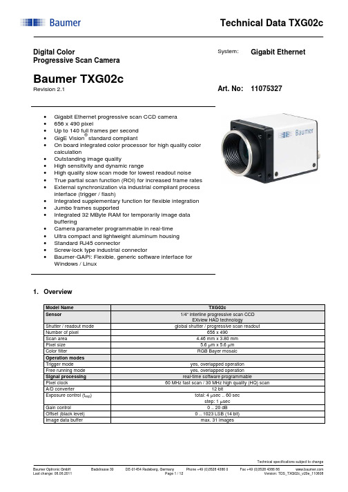
Digital ColorProgressive Scan CameraSystem: Gigabit Ethernet Baumer TXG02cRevision 2.1 Art. No: 11075327•Gigabit Ethernet progressive scan CCD camera•656 x 490 pixel•Up to 140 full frames per second•GigE Vision® standard compliant•On board integrated color processor for high quality color calculation•Outstanding image quality•High sensitivity and dynamic range•High quality slow scan mode for lowest readout noise •True partial scan function (ROI) for increased frame rates •External synchronization via industrial compliant process interface (trigger / flash)•Integrated supplementary function for flexible integration •Jumbo frames supported•Integrated 32 MByte RAM for temporarily image data buffering•Camera parameter programmable in real-time•Ultra compact and lightweight aluminum housing•Standard RJ45 connector•Screw-lock type industrial connector•Baumer-GAPI: Flexible, generic software interface forWindows / Linux1. OverviewModel Name TXG02cSensor 1/4“ interline progressive scan CCDEXview HAD technology Shutter / readout mode global shutter / progressive scan readout Number of pixel 656 x 490Scan area 4.46 mm x 3.80 mmPixel size 5.6 µm x 5.6 µmColor filter RGB Bayer mosaicOperation modesTrigger mode yes, overlapped operationFree running mode yes, overlapped operationSignal processing real-time software programmablePixel clock 60 MHz fast scan / 30 MHz high quality (HQ) scan A/D converter 12 bitExposure control (t exp) total: 4 µsec .. 60 secstep: 1 µsec Gain control 0 .. 20 dBOffset (black level) 0 .. 1023 LSB (14 bit)Image data buffer max. 31 imagesImage acquisitionCamera image format modes Format(pixel) Gen<I>CamstandardFormatIDPixelformatPixelclockMHzFramesper sec.*)t readoutBayerRG8BayerRG12Mono8YUV411 PackedYUV422 Packed **)YUV444 PackedRGB8 PackedFull frame HQ slow 656 x 490 Vendorspecific00BGR8 Packed30 70 15 msecBayerRG8BayerRG12Mono8YUV411 PackedYUV422 Packed **)YUV444 PackedRGB8 PackedFull frame fast 656 x 490 yes 01BGR8 Packed60 140 8 msecStandard featuresImage size controlsPixel format BayerRG8, BayerRG12, Mono8, YUV411 Packed, YUV422 Packed, YUV444 Packed,RGB8 Packed, BGR8 PackedTest image selector yes, in all modesOff, GreyHorizontalRamp, GreyVerticalRamp,HorizontalLineMoving, VerticalLineMovingHorizontalAndVerticalLineMovingPartial scan yes, format freely programmable in all modesAnalog controlsGain yesBlack Level (Off set) yesGamma noAcquisition and TriggerAcquisition mode ContinuousAcquisition frame rate yes, ON / OFF (only in freerunning mode)0 .. 829 Hz,step: 0.01 HzTrigger source HardwareTrigger (Line0), SoftwareTrigger, CommandTrigger (ActionCommand), All or Off Trigger delay 0 .. 2 sec, 512 trigger can be tracked,step: 1 µsecSequencer noDigital I/OLines Input: Line0, Output: Line1Line source (outputs only) Line1: Off, ExposureActive, Timer1, ReadoutActive, User0,TriggerReady, TriggerOverlapped, TriggerSkippedLine debouncer yes, low and high signal separately selectable0 .. 5 msecstep: 1 µsecEvent GenerationEvents GigEVisionError, Heartbeattimeout, EventLost, Line0RisingEdge, Line0FallingEdge,Line1RisingEdge, Line1FallingEdge, ExposureStart, ExposureEnd, FrameStart, FrameEnd,TriggerReady, TriggerOverlapped, TriggerSkippedEvent Notification yes, ON / OFFCounters and TimersFramecounter yes, 232can be set by userTimer yes,TimerSelector: Timer1TimerTriggerSource:Off, Input: Line0, SoftwareTrigger, CommandTrigger (ActionCommand),ExposureStart, ExposureEnd, FrameStart, FrameEnd, TriggerSkippedTimerDelay: 0 µsec .. 2 sec, step: 1 µsecTimerDuration: 10 µsec .. 2 sec, step: 1 µsecLUT ControlsLUT selector noDefect pixel correction (custom) yes, ON / OFFDefect pixel list (custom) yes, max. 256 pixel coordinates (x, y) can be stored GigEVisionTransportLayerPayLoadsize 4 Byte .. 648.400 ByteTransmissionDelay (custom) 0 .. 232-1 ticksUserSetsUser set selector Default (factory settings / read only)UserSet1, UserSet2, UserSet3 (read and write) UserSetDefaultSelector yes, define the start up “UserSet”Advanced featuresTime stamp function yes, 64 bittick = 32 nsecAsynchronous message channel yesConcatenation function yesUser defined identifier yes, user programmable permanent identifierActionCommand yes, ID 0 = TriggerDeviceTemperature noData quality at 20 °C, gain = 1, exposure time = 32 msec,full frame mode, slow scanReadout noise σ < 0.5 LSB (8 bit) typicalDynamic range typical > 54 dBOptical interface C-Mounton request: CS-MountOptical filter Hoya E-CM500Son request: dust protection, daylight filter or no filterProcess interface functionsAsync. Trigger yes, trigger mode operation,“Off”, “software trigger”, “hardware trigger”, “command trigger” or “all” separately selectable(overtriggered signals and trigger signals during the readout timewill be notified in the received image header)Exposure Active (External flash sync)yes,delay_value (t delay flash) ≤ 4 µsec, duration_value (t duration): slow mode = t exp + 28 µsec fast mode = t exp + 14 µsecUser Output yes, ON / OFF Timer yes, Timer1 Software reset yes, delay up to 102 msecAsynchronous reset Full frame slowfast delay up to 2,5 msec 1,3 msecImage info header yesElectrical interfaceData / control standard single cable 1000 Base-T,Cat6 recommended / minimum Cat5eoption: screw lock type connectorPower VCC: 8 VDC .. 30 VDCI: 450 mA .. 120 mAPower consumption approx. 3.6 WattDigital input Line 0: trigger signal, opto decoupledU IN(low) = 0 .. 4.5 VDC, U IN(high) = 11 .. 30 VDCI IN = 6 .. 10 mA / 7 mA typicalrising edge (invert = false) ****)min. impulse length (t min): 2 µsectrigger delay out of t readout (t delay trigger): 1 µsecmax. trigger delay during t readout (t delay trigger): slow mode = 28 µsecfast mode = 14 µsec Digital output Line 1: opto decoupledU EXT = 5 .. 30 VDC / 24 VDC typical, I OUT = max. 16 mAhigh active (invert = false) ****)LED 1:2: green:yellow:green:green flash:yellow:yellow/red flash:Power onReadout activeLink Phy (1 GBit)Ethernet RXEthernet TXEthernet RX/TXEnvironmentalStorage temperature -10 °C .. +70 °COperating temperature +5 °C .. +50 °C ****)between +26 °C .. +50 °C, note the max. housing tem perature Housing operating temperature max. +50 °CHumidity 10 % .. 90 % non condensingConformity CE, FCC Part 15 class B, UL, RoHS compliantHousing aluminum, IP40Dimensions 36 x 36 x 48 mm3Weight < 90 g1000 Base-T interface 1000BASE-T (1000 Mbit / sec)Ethernet IP configuration persistent IP / DHCP / LLAStream channel packet size 576 Byte (default) .. 65535 Bytejumbo frames supportedInterpacketgap 0 .. 232-1 ticksMulticast function yesResend function yesBaumer-GAPI SDK with supported OS socket driver and Baumer filter driver / SoftwareSDK for Windows XP (32 bit) / Windows Vista (32 bit / 64 bit) / Windows 7 (32 bit / 64 bit) /Linux Kernel 2.6.xx (64 bit / 32 bit)GigE Vision® compatible programs and image processing libraries supportedWindows / Linux depending on the actually driver software is used*)maximum frame rate in free running mode, effective frame rate depending on camera image format mode settings and set exposure time (t exp < t readout)**)default pixel format***) can be inverted via software****)housing temperature is limited by CCD sensor specification2. Camera Factory Settings after Camera Start-upCamera factory settings after camera start-up Operation modes free running modeSignal processingExposure control 32 msecGain control factor 1 = 0 dBOffset (black level) 0Image acquisitionCamera image format mode mode id = 01, full frame YUV422 PackedPartial scan function not activeAcquisition frame rate OffTimer OffTransmission delay 0 ticksTest image selector OffDefect pixel correction OnElectrical interfaceDigital input 1: Line0disabled, digital output set to low status (high impedance)invert = falseline source = Exposure Active Digital output 1: Line1disabledinvert = falsetrigger source = Line03. Timing Operation ModesTrigger Mode: start up timeTrigger Mode: trigger mode 0, overlapped triggerexposurereadouttriggerparameter *Frame n effectiveready for trigger **parameter *Frame n+1effectiveflasht exp < t readout : t earliest possible trigger (n+1) = t readout(n) - t exp(n+1)t exp > t readout : t earliest possible trigger (n+1) = t exp(n)t exp < t readout : t not ready (n+1) = t exp(n) + t readout(n) - t exp(n+1)t exp > t readout : t not ready (n+1) = t exp(n)* image parameter: offsetglobal gain modepartial scan** signal will be notified as event “TriggerReady” and is not available as digital outputTrigger Mode: trigger mode 0, overlapped trigger , when t exp (n+2) > t exp (n+1)exposurereadouttriggerready for trigger **flasht exp < t readout : t earliest possible trigger (n+1) = t readout(n) - t exp(n+1)t exp > t readout : t earliest possible trigger (n+1) = t exp(n)t exp < t readout : t not ready (n+1) = t exp(n) + t readout(n) - t exp(n+1)t exp > t readout : t not ready (n+1) = t exp(n)parameter *Frame n effectiveparameter *Frame n+1effective* image parameter: offset global gain modepartial scan** signal will be notified as event “TriggerReady” and is not available as digital outputTrigger Mode: trigger mode 0, overlapped trigger , when t exp (n+2) < t exp (n+1)exposurereadouttriggerready for trigger **flashFrame n+2not started / overtriggeredt exp < t readout : t earliest possible trigger (n+1) = t readout(n) - t exp(n+1)t exp > t readout : t earliest possible trigger (n+1) = t exp(n)t exp < t readout : t not ready (n+1) = t exp(n) + t readout(n) - t exp(n+1)t exp > t readout : t not ready (n+1) = t exp(n)parameter *Frame n effective parameter *Frame n+1effective* image parameter: offsetglobal gain modepartial scan** signal will be notified as event “TriggerReady” and is not available as digital outputFree Running Mode: overlapped operationexposure readoutparameter *Frame n-1parameter *Frame nparameter *Frame n+1flash* image parameter: offsetglobal gainmodepartial scan4. Housing5. Connectors / Electrical Interfaces5.1 Pin assignment:*) resistor must be used, I OUT = 16 mA by = 24 VDC recommended, drawing shown above example for using high active signal *) shielded trigger / flash cable should be used and orderedseparatelyTechnical Data TXG02cTechnical specifications subject to changeBaumer Optronic GmbHBadstrasse 30 DE-01454 Radeberg, Germany Phone +49 (0)3528 4386 0 Fax +49 (0)3528 4386 86 Last change: 08.06.2011 Page 11 / 12 Version: TDS_TXG02c_v20e_110608 5.2 Flash sync sample U EXT = 24 VDC high active:t ON time = typ. 2 µsect OFF time = typ. 40 µsec OFFONTiming example:measurement condition U EXT = 24 VDC / I OUT = 16 mA R L = 1.5 kOhm5.3 Flash sync sample U EXT = 24 VDC low active:t ON time = typ. 2 µsect OFF time = typ. 40 µsec EXTTiming example:measurement condition U EXT = 24 VDC / I OUT = 16 mA R L = 1.5 kOhmEnd of Document。
千兆网相机用户手册_V0.2..
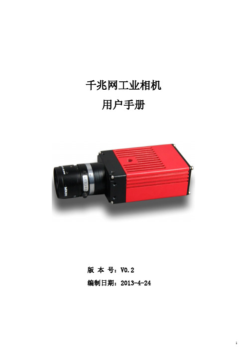
千兆网工业相机用户手册版本号:V0.2编制日期:2013-4-24目录一、产品介绍 (3)1.1. 产品简介 (3)1.2. 产品特色 (3)1.3. 产品参数表 (4)1.4. SENSOR光谱曲线图 (6)1.5. 产品外观尺寸 (6)1.6. 镜头接口与滤光片间距 (7)1.7. 摄像机接口 (8)二、产品特色描述 (8)三、电脑配置要求 (9)四、相机使用前的准备说明 (9)4.1. 安装使用前的准备 (9)4.1.1 网卡巨帧的设置 (9)五、相机使用注意事项 (16)六、产品使用注意事项 (16)七、常见使用问题解答 (17)八、附注: (17)一、产品介绍1.1.产品简介GE系列千兆网工业相机是由我司专门针对需要长距离高速传输图像和多相机系统的工业应用领域而设计的。
100米@1Gbps稳定传输;向下兼容百兆网;相机硬件支持GIGE VISION标准;内置图像缓存及图像处理电路(ISP),可大大减轻CPU负担。
采用高品质CCD图像传感器,及12PIN Hirose工业连接器。
产品体积仅为86.5×50×30mm。
GE系列千兆网工业相机支持TWAIN和DirectShow接口,全面兼容Windows XP(32位)、Win7(32/64位) 、 Win8(32/64位)操作系统。
本相机适用于机器视觉、多相机系统、工业远程监控、教学等领域。
1.2.产品特色●硬件支持GIGE VISION标准;●100米@1Gbps稳定传输;●内置32MB图像缓存,内置图像处理电路;●支持单PC 8台相机同时稳定工作;●与USB产品使用统一软件平台,二次开发和安装非常方便;●支持TWAIN和Directshow接口;●支持低分辨率高速预览,全分辨率拍照;●独特的Rubber防尘结构。
1.3.产品参数表●产品软件安装与使用请详见《BasedCam软件使用手册》。
●ROI是指从最大分辨率的画面中裁剪一块小分辨率画面,此模式下帧率可以提高,视角会变小; SUM是指SENSOR的相邻像素累加,此模式下分辨率降低,灵敏度能大幅提高; BIN 是指SENSOR的相邻像素累加后再取平均,此模式下分辨率降低,灵敏度不变,但图像噪声更小。
TIS千兆网相机使用说明
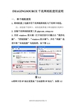
IMAGINGSOURCE千兆网相机使用说明一. 单个相机使用1. 将相机接上电源并用千兆网线将相机与千兆网卡相连。
注:请连接千兆网卡,切勿连接普通上网功能的百兆网卡2. 安装千兆网相机配置工具gigecam_setup.exe3. 关闭windows防火墙(打开该页面可右键点击“我的电脑”- “控制面板”-“windows防火墙”),并在“高级”选项中将“本地连接”勾选取消,如下图1.1:图1.14.将网卡的IP地址设置成“自动获得IP地址”,如图1.2图1.25. 等待网卡IP自动获取完毕(大概1~2分钟)6. 打开GigECam IP Config,此时就可以找到当前已经连接的相机,点击“Device”会出现黄色的感叹号,如图1.3,说明相机和网卡的IP不在同一字段,此时既可以设置相机的IP来适应网卡的IP也可以设置网卡的IP来适应相机的IP。
①以设置网卡来适应相机的IP为例:查看GigECam IP Config中“IP Address”相机的IP地址,如“169.254.205.46”,然后打开网卡的IP设置,选择“使用下面的IP地址”,将网卡的IP设置成与相机的IP在同一字段,即“IP地址”中前三个数字一样,最后一个不一样,如“169.254.205.45”.“子网掩码”填“255.255.255.0”,其他不用填写,如图1.4,关闭网卡的IP设置。
此时“Device”图标就恢复成正常的相机图标,且相机的4个属性页面全部显示出来,如图1.5。
图1.3图1.4图1.5②以设置相机来适应网卡的IP为例:在GigECam IP Config 中将页面切换到“Temporary IP Address”将“IP Address”填入“192.168.1.1”,“Subnet Mask”填入“255.255.255.0”,“Defalt Gateway”不填,并点击“Force IP”强行设置相机的IP地址,如图1.6。
快速以太网 无线802.11b g互联网摄像头简单安装指南说明书
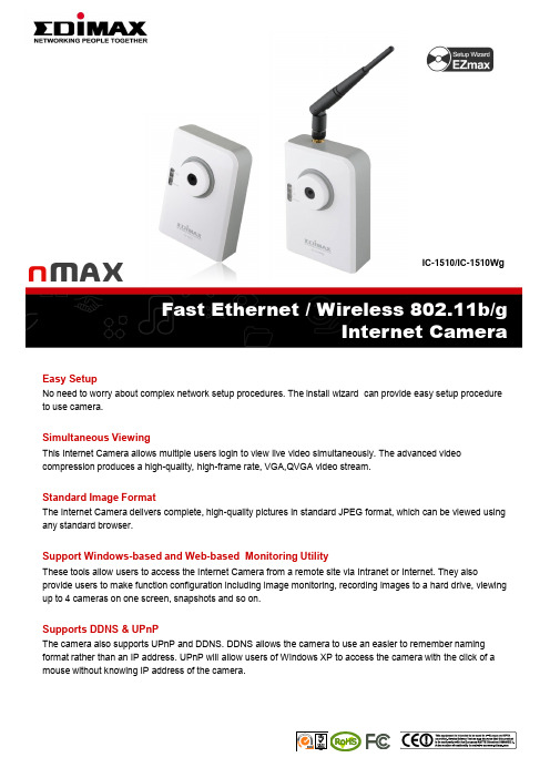
IC-1510/IC-1510WgFast Ethernet / Wireless 802.11b/gInternet CameraEasy SetupNo need to worry about complex network setup procedures. The install wizard can provide easy setup procedure to use camera.Simultaneous ViewingThis Internet Camera allows multiple users login to view live video simultaneously. The advanced video compression produces a high-quality, high-frame rate, VGA,QVGA video stream.Standard Image FormatThe Internet Camera delivers complete, high-quality pictures in standard JPEG format, which can be viewed using any standard browser.Support Windows-based and Web-based Monitoring UtilityThese tools allow users to access the Internet Camera from a remote site via Intranet or Internet. They also provide users to make function configuration including image monitoring, recording images to a hard drive, viewing up to 4 cameras on one screen, snapshots and so on.Supports DDNS & UPnPThe camera also supports UPnP and DDNS. DDNS allows the camera to use an easier to remember naming format rather than an IP address. UPnP will allow users of Windows XP to access the camera with the click of a mouse without knowing IP address of the camera.FEATURES AND TECHNICAL SPECIFICATIONSINTERFACE MANAGEMENT POWER ADAPTER1 Ethernet ( RJ-45) Port1 Power Jack1 Reset Button1 External Detachable Antenna (IC-1510Wg)Provides Admin Utility, CameraViewer & Web browser managementFirmware upgradeableDC 12V, 0.4ALED HARDWARE HUMIDITYLAN WLAN Power 0.3M Pixels CMOS SensorManual Focus, F= 2.8mm2 MB Flash16 MB SDRAM10-90%(Non-condensing)FUNCTIONS DIMENSION & TEMPERATURE CERTIFICATIONS•Motion-JPEG Image Video•Digital 24-bit Color•Provides Manual Focus Lens•Supports Up to 20 fps Video Frame Rate•High Speed Hardware-Based Image Compression •Includes easy-to-use Viewer & Recorder utility•Provide Admin utility, Camera Viewer & WEB browser Management•Supports Wireless 802.11b/g configuration•View multiple cameras simultaneously -Up to 4 at a time •Supports four additional user accounts for viewing camera •Manual/Schedule/Cycle Record, Video•Playback/Forward/Pause/Stop•Supports Motion-Detection•Firmware Upgradeable114X 79X 50mm0~45 ℃CE, FCC, C-TickSYSTEM REQUIREMENTS•OS System: Windows 98 , ME , 2000, XP +SP2,Server 2003•IE Version: 6.0.29 + SP2 or above•CPU: Intel Pentium III 750MHz above orIntel Celeron 1GHz above•Memory Size: 128MB (256MB recommended)•DirectX 9.0 or above•VGA card with fully DirectX 9.0 supported.•VGA Card Resolution: 800 x 600 or aboveNETWORK SETUP DIAGRAM AND RELATED PRODUCTSAn example of how the IC-1510Wg can be setup:• Connect the IC-1510Wg to PC by Ethernet (RJ45) LAN port.• Install the Admin Utility into your PC and set up the IC-1510Wg IP subnet as same as Broadband Router’s.• Configure IC-1510Wg with Broadband Router via wireless connection.•All computers in the local network can now view the IC-1510Wg.• To view the IC-1510Wg via the Internet, open the http and video ports in the router. Then, you can watch live video from anywhere in the world.。
basler调相机规范步骤
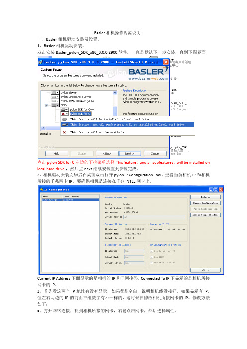
Basler相机操作规范说明一、Basler相机驱动安装及设置。
1、Basler相机驱动安装。
双击安装Basler_pylon_SDK_x86_3.0.0.2900软件,一直是默认下一步安装,直到下图界面点击pylon SDK for C左边的下拉菜单选择This feature,and all subfeatures,will be installed on local hard drive.,然后点next继续安装直到安装完成。
2、相机驱动安装完毕后在桌面双击打开pylon IP Configuration Tool,查看当前相机IP和相机所接的千兆网卡IP。
要确保相机是连接在千兆INTEL网卡上。
Current IP Address下面显示的是相机的IP和子网掩码,Connected To IP下显示的是相机所接网卡的IP。
3、首先看这两个IP地址有没有显示,如果都是空白,说明相机线没接好。
如果显示有IP,但左右两边的IP的前面三组数字有不一样的,这时候要修改相机所接网卡的IP。
修改方法如下:a、打开网络连接,找到相机所接的网卡,右键点击网卡,然后选择属性。
b、找到网络—此连接使用下列项目—Internet协议(TCP/IP),选中Internet协议(TCP/IP),点下方的属性。
一般刚开始是默认使用“自动获取IP地址”,我们要选“使用下面IP地址”,然后查看pylon IP Configuration Tool软件的IP地址,手动填写网卡的IP,IP的前三组数字一定要和相机的IP一样,最后一组数字一定要和相机的IP的不一样。
填完IP,用鼠标点一下子网掩码,一般自动生成数字,看一下跟相机的子网掩码(subnet Mask)是否一样,不一样就修改网卡的子网掩码使它跟相机的子网掩码一样。
然后点击确定,回到前一个界面,勾选上“连接后在通知区域显示图标”,最后点击确定完成IP地址的设定。
4、防火墙的设置。
相机IP修改说明
相机IP修改说明书
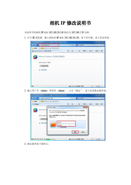
本说明书将相机IP地址:192.168.20.130修改为192.168.5.20为例。
1.打开IE浏览器,输入相机的IP地址19
2.168.20.130,按下回车键,进入登录界面。
2.输入用户名(admin)和密码(admin),点击“确定”,进入登录路由器界面。
3.路由器界面下图所示。
4.选择“全景外网”,进入查看外网信息。
5.“全景外网”信息显示如下图。
5.相机IP修改“IP地址”,“默认网关”,“DNS服务器1”,如相机IP修好为192.168.5.20,具体修改如下图所示,点击“保存”。
6.修改完成,点击“立即重启”,重启需要一定时间,重启完成之后相机IP修改成功。
7.再次在IE浏览器输入192.168.5.20,可以成功登录,如下图所示。
千兆网相机用户手册_V0.2

千兆网相机用户手册_V0.2 千兆网工业相机用户手册版本号:V0.2编制日期:2013-4-24目录一、产品介绍 (3)1.1. 产品简介 (3)1.2. 产品特色 (3)1.3. 产品参数表 (4)1.4. SENSOR光谱曲线图 (6)1.5. 产品外观尺寸 (6)1.6. 镜头接口与滤光片间距 (7)1.7. 摄像机接口 (8)二、产品特色描述 (8)三、电脑配置要求 (9)四、相机使用前的准备说明 (9)4.1. 安装使用前的准备 (9)4.1.1 网卡巨帧的设置 (9)五、相机使用注意事项 (16)六、产品使用注意事项 (16)七、常见使用问题解答 (17)八、附注: (17)一、产品介绍1.1.产品简介GE系列千兆网工业相机是由我司专门针对需要长距离高速传输图像和多相机系统的工业应用领域而设计的。
100米@1Gbps稳定传输;向下兼容百兆网;相机硬件支持GIGE VISION标准;内置图像缓存及图像处理电路(ISP),可大大减轻CPU负担。
采用高品质CCD图像传感器,及12PIN Hirose工业连接器。
产品体积仅为86.5×50×30mm。
GE系列千兆网工业相机支持TWAIN和DirectShow接口,全面兼容Windows XP(32位)、Win7(32/64位) 、Win8(32/64位)操作系统。
本相机适用于机器视觉、多相机系统、工业远程监控、教学等领域。
1.2.产品特色●硬件支持GIGE VISION标准;●100米@1Gbps稳定传输;●内置32MB图像缓存,内置图像处理电路;●支持单PC 8台相机同时稳定工作;●与USB产品使用统一软件平台,二次开发和安装非常方便;●支持TWAIN和Directshow接口;●支持低分辨率高速预览,全分辨率拍照;●独特的Rubber防尘结构。
1.3.产品参数表●产品软件安装与使用请详见《BasedCam软件使用手册》。
【网络摄像机ip如何设置】大华网络摄像机ip设置

【网络摄像机ip如何设置】大华网络摄像机ip设置现在很多超市等企业都有录像机,但是内网的ip地址很多人都不会设置。
小编为大家整理了怎么设置网络摄像机ip地址的相关内容,供大家参考阅读!网络录像机设置内网IP的方法新买的网络摄像机都有生产厂家设置的默认ip地址,有的是192.168.1.10或192.168.1.9,有的是192.168.0.几的,通过这个ip地址可以在这个局域网内被发现,然后对它进一步修改,一般在摄像机的背面或底部可以看到默认iP地址,还有帐号和密码。
下面开始操作。
2网络摄像机接上电源以后,用网线和电脑(最好是笔记本,比较方便)连接。
有的网络摄像机使用POE供电,只需要用一根网线与POE交换机连接,这时候电脑(笔记本)要和POE交换机的网线口连接。
3准备就绪,电脑打开浏览器,地址栏输入上面看到的默认ip地址,回车。
页面打开以后,会提示你安装插件,点击确定下载安装。
安装完成以后刷新一下页面,出现登录页面,输入你看到的帐号(多数是admin)和密码(多数没有密码),点击登录按钮。
4点击设备配置--系统设置--网络设置,看到修改ip的界面了,这里给它配置一个固定的ip地址,其他默认就可以了。
另外,点击设备配置--系统设置--输出模式,看到“通道名称”,点击设置,给这个摄像头起个名称,这样在多个通道中容易辨认。
END批量修改网络摄像机ip地址有时候在单位安装的监控点较多,一个一个修改太麻烦,我们可以借助“网络视频集中管理软件”来修改网络摄像机ip 地址。
目前用得多的是cms监控软件,在百度搜索下载安装。
运行程序,在登陆界面只输入用户名super,点击登录。
在软件界面,点击:系统设置--监控点管理,弹出界面点击第一个图标:添加区域,下面给这个区域起个名称,点击确定。
在区域列表里面点击刚刚新建的区域,看到“添加设备”图标亮起,点击这个图标,弹出添加设备窗口。
点击“ip搜索”,稍等片刻看到了所有在局域网内的网络摄像机。
IPCAMERA使用手册

IPCAMERA使用手册B系列——机器人款I P C a m e r a(网络摄像机)2011年7月版本V4.18使用手册目录1产品概述 (4)1.1产品包装 (4)1.2功能介绍 (4)1.3技术参数 (4)2设备外观与接口 (6)2.1设备外观 (6)2.2设备接口 (6)3从局域网访问IP CAMERA (7)3.1局域网连接方式 (7)3.2搜索与设置设备的IP地址 (7)3.3访问IP C AMERA (8)4从互联网访问IP CAMERA (10)4.1互联网连接方式 (10)4.2端口映射 (11)4.3动态域名(DDNS) (11)4.3.1厂家动态域名 (11)4.3.2第三方动态域名 (12)5其它设置 (12)5.1网络设置 (12)5.1.1基本网络设置 (12)5.1.2WIFI设置 (12)5.1.3ADSL设置 (13)5.1.4UPnP设置 (13)5.1.5DDNS设置 (13)5.1.6MSN设置 (14)5.2告警设置 (14)5.2.1告警设置 (14)5.2.2邮件服务设置 (16)5.2.3FTP服务设置 (16)5.2.4告警服务器设置 (17)5.3高级设置 (17)5.3.1用户设置 (17)5.3.2多路设置 (18)5.3.3其它设置 (18)5.4系统维护 (19)5.4.1设备信息查看 (19)5.4.2设备时钟设置 (19)5.4.3设备固件升级 (20)5.4.4恢复出厂设置 (20)5.4.5日志 (20)6集中监控 (20)7问题解答 (21)1 产品概述IP Camera集成了网络和web服务功能,可以把摄制的视频通过网络传送到任何地方,您只需通过web浏览器就可随时访问现场视频。
它可以应用在大型卖场、学校、工厂、家庭等一系列场所。
1.1 产品包装网络摄像机* 15V电源适配器 * 1固定支架 * 1工具光盘 * 1网线 * 1注意:如果选择带wifi功能的设备,包装内配有发射天线。
千兆网相机知识

互联网协议(IP)原理
互联网协议(IP)原理
主机 主机 主机 主机
IP 数据包
交换机
路由器
子网
其他子 网
互联网协议(IP)原理
Host
Host
Host
Host
主机-即用于连接到网络的设备。 可以是插有 网卡的计算机、GigE相机等
IP Data Packet
Switch
Router
每一个主机必须在网络上有唯一的IP地址
GigE相机系统设计指南
GigE Vision 相机的带宽计算
• 如何决定相机的数据带宽输出?
举例:
假设我们使用500万像素的Basler Ace acA2500-14gc 这款相机,每帧=2590 x 1942 像素(pixels) 在Bayer8彩色模式下,每像素占8bits=1byte 数据 所以,每帧= 2590 x 1942 x 1byte = 5,029,780 bytes 在14fps的速度下,总带宽输出= = 5,029,780 x 14 = 71MB/s
IP = 192.168.1.3 Subnet mask = 255.255.255.0
Switch
Router
Subnet = 192.168.1.0
注意: 您在设置时,不可以使用0和255做主机ID, 这两个数为特殊保留数,例如 192.168.1.0, 192. 168. 1.255
其他子 网
互联网协议(IP)原理
IP地址和子网掩码
•单播:共有3个预设IP地址类型:
•Class C 是小型网络中最常见的,例如192. 168. 1. 1
互联网协议(IP)原理
互联网协议(IP)原理
IP Camera网络摄像机用户手册(V2.2)

I P C a m e r a 网络摄像机(V2.2)用户使用手册2008-11-26序言感谢您选择了本公司的网络摄像机系列产品网络摄像机是基于网络的视频监控产品,它包括网络摄像机硬件主体、网络摄像机软件配置二个部分。
在您使用我们的产品之前,敬请您仔细阅读本产品的使用说明。
说明本说明书所讲述的内容可适用于各系列的各型号网络摄像机,包括网络固定枪机,网络红外枪机,网络红外半球,网络匀速球,网络高速球等系列。
本手册主要围绕网络固定枪机的使用说明展开本说明书详细讲述了网络摄像机的操作方法和性能指标文中以IP地址192.168.1.100为例进行网络参数的设置在使用网络摄像机之前,建议您仔细阅读本操作手册,按手册所讲述的步骤安装,使用系统文中标红色的字体是需要特别注意的部分物品清单在您拆开网络摄像机包装后,请仔细按如下表格核对附件清单装箱清单产品型号产品规格数量软件版本 1单路整机一路 1电源(含电源线)DC12V 1电阻 4.7K 46P 1 接线端子说明书中文 1光盘 1合格证 1保修卡中英文通用 1申明本手册所描述的内容可能与您现使用的软件版本有区别,如果您按照本手册使用时遇到有无法解决的问题,请及时与本公司技术支持部或产品供应商联系本手册内容将不定期更新,本公司有保留不另行通知的目录1.1主要功能及特点 (4)1.2网络摄像机的清洁,维护 (7)1.3应用领域 (7)第二部分:外观及安装 (8)2.1运行环境 (8)2.2网络摄像机外观结构 (9)2.3网络摄像机的连接 (11)第三部分:网络摄像机的访问 (11)3.1检索设备 (11)3.2修改网络摄像机IP地址 (12)3.3通过IE浏览器登录视频服务器 (13)3.4通过数字视频管理中心软件登录网络摄像机 (13)第四部分:NVS配置 (15)4.1图像实时预览 (15)4.2通道设置 (16)4.3OSD和遮挡设置 (17)4.4网络设置 (18)4.4.1 自动获得IP地址 (18)4.4.2 使用固定IP地址 (19)4.4.3 服务器在线通知 (19)4.5COM设置 (20)4.6告警及事件管理 (21)4.7视频移动告警设置 (21)4.8视频丢失告警设置 (23)4.9探头告警设置 (24)4.10探头输出设置 (26)4.11PPP O E&DDNS设置 (26)4.12移动磁盘录像设置 (28)4.13FTP上传设置 (29)4.14E M AIL上传设置 (30)4.15中心平台接入配置 (31)4.16WIFI设置 (33)4.17系统设置 (33)4.18用户权限设置 (35)附录一动态域名解析的设置 (36)附录二NVS在不同网络环境下的访问 (41)附录三图像设置技巧 (43)第一部分:产品概述网络摄像机系列采用嵌入式实时多任务操作系统(RTOS)和嵌入式处理器,完全脱离PC平台,系统调度效率高,代码固化在FLASH中,系统运行更加稳定可靠。
Baumer工业相机指南
User‘s GuideIP Configuration Tool for Gigabit Ethernet Cameras Microsoft® Windows®Document Version: v2.3Release: 27.11.2013Document Number: 11037724231. Introduction42. General System Requirements43. Installation Procedure44. Startup Behaviour 55. Graphical User Interface (GUI) 55.1. Available Cameras 55.2. Available Interfaces 55.3. Options55.4. Persistent IP Options5Table of Contents5.5. User-defined Name 55.6. Camera Information55.7. Force-IP Options 55.8. Rescan Button56. Trouble Shooting 66.1. Camera in wrong subnet66.2. Camera in use by other application 66.3. Logging67. Support6Introduction 1.The GigE Vision™ standard, which also covers the UDP application protocol, offers a variety of possible configurations of the IP address and subnet mask for cameras for profes-sional machine vision.Errors can occur when establishing connections between the PC and camera due to unintended, incorrect operation or connection of a camera to another network.In this case the Force-IP feature, as defined in the GigE Vision™ stan-dard, may be the last solution. Usingthis feature, it is possible to force acamera into a valid network tempo-rarily, making the device accessibleagain. Once Force-IP is complete,the camera can be set to LLA orDHCP, or a persistent IP can be as-signed.In larger multi-camera systems, theprocessing of Force-IP may take aconsiderable amount of time andcan easily become unmanageable.With the introduction of the “IP Con-figuration Tool for Gigabit Ethernet Cameras”, Baumer gives you theoption to check whether cameras ina multi-camera system are reach-able.If one or more cameras are notreachable, the tool provides pro-cesses for fully automatic Force-IP.Furthermore, the user is able toset several IP parameters, whichare specified in the GigE Vision™ standard. The easy to understandGraphical User Interface (GUI)makes IP configuration as simple as possible.General System Requirements2.Installation3.ProcedureBaumer GigE IPConfig is provided as a standard ZIP file. In order to in-stall this tool, simply extract the file. Next, enter the path (Extract to:), for where you wish to install Baumer GigE IPConfig (Fig. 1).After this, all required files will be copied to your system.Fig. 1: Path selection for Baumer GigE IPConfig45Fig. 2: Baumer GigE IPConfig GUIlower-level ones (LLA, DHCP , Per-sistent IP) are read from the cam-era's flash memory. Force-IP options5.7. If Baumer GigE IPConfig detects one or more cameras in an incor-rect subnet 5), the “Force-IP options” (Fig. 3) will appear in the upper part of the GUI.Here, it is possible to temporarily force a valid IP subnet combination on the camera 6). Once this is com-plete, the camera can be located in the correct subnet by using the con-nection options described in sec-tions 5.3 and 5.4.Rescan button5.8. Once one or more cameras havebeen de-energized and then re-en-ergized, the effects of the changes made can be checked by runninga new scan for available interfaces and cameras. 5) Cameras in incorrect subnets will bedisplayed in blue.6) If you click on the “Force-IP” or“Force-IP all” buttons, a window will appear containing information about itsprogress.Startup Behavior4. On startup, the tool scans for all available network interface cards (NIC) and cameras.If one or more cameras are in an incorrect subnet, the tool will inform you of this by displaying “Force-IP Options”1).Graphical User 5. Interface (GUI)The GUI of Baumer GigE IPConfig (Fig. 2) is divided into several ar-eas:Available cameras ▪Available interfaces▪Config options (for establishing ▪connections)User-defined name ▪Camera information ▪Force-IP Options.▪Available cameras5.1. This list provides information such as type and serial number of the connected cameras.For any setting, one of these cam-eras must be selected.Available interfaces5.2. Here, all available NICs and their IP parameters are displayed.Options5.3. If a camera is selected 2), Baumer GigE IPConfig gives you the option to switch this camera to one of three mechanisms for establishing con-nections:LLA ▪3) (Link Local Address)DHCP (Dynamic Host Configura - ▪tion Protocol) and Persistent IP .▪1) Please see Section 5.7.2) The camera must also be in the correctsubnet.3) Changes are written directly to the cam-era's flash memory.Persistent IP options5.4. Once “Persistent IP” is selectedwithin “Options”4), this area will be-come activated.The desired IP address and subnetmask for the selected camera canbe entered here.Changes are transferred to the cam-era by clicking the “set” button.User-defined name5.5. A user-defined name for the select -ed camera can be assigned here.This string can be up to 15 charac-ters long.Camera information 5.6. A variety of information about the selected camera is displayed within this area.The currently valid parameters areread from the camera's registry, the4)Please see Section 5.3.Fig. 3: Force-IP options6.Troubleshooting6.1.Camera in incorrectsubnetPlease see section 5.7 of this guide.6.2.Camera in use by otherapplicationIf a camera is being used by another application, the IP Configuration Tool will not have exclusive access to the device. In this case, the respective camera (type and serial number) is displayed in red.Please close the other application ac-cessing the camera and rescan.6.3.LoggingA log file, which records any action performed using the IP Configuration Tool is stored in the installation direc-tory of the Tool.Support7.In case of any questions or for trou-bleshooting please contact our sup-port team.WorldwideBaumer Optronic GmbH Badstrasse 30DE-01454 Radeberg, Germany Tel: +49 (0)3528 4386 845Email: support.cameras@baumer. comWebsite: 6NOTE: .................................................................................................................................................................................... .................................................................................................................................................................................... .................................................................................................................................................................................... .................................................................................................................................................................................... .................................................................................................................................................................................... .................................................................................................................................................................................... .................................................................................................................................................................................... .................................................................................................................................................................................... .................................................................................................................................................................................... .................................................................................................................................................................................... ................................................................................................................................................................................... .................................................................................................................................................................................... .................................................................................................................................................................................... .................................................................................................................................................................................... .................................................................................................................................................................................... .................................................................................................................................................................................... .................................................................................................................................................................................... .................................................................................................................................................................................... ..................................................................................................................................................................................7Baumer Optronic GmbH Badstrasse 30DE-01454 Radeberg, GermanyPhone +49 (0)3528 4386 0 · Fax +49 (0)3528 4386 86sales@ · T e c h n i c a l d a t a h a s b e e n f u l l y c h e c k e d , b u t a c c u r a c y o f p r i n t e d m a t t e r i s n o t g u a r a n t e e d .S u b j e c t t o c h a n g e w i t h o u t n o t i c e . P r i n t e d i n G e r m a n y .。
baumer VLXT.FO 相机 (10 千兆以太网) 快速入门指南说明书
Conformity / SafetyFurther InformationFor further information on our products visit For technical issues, please contact our technical support:************************** · Phone +49 (0)3528 4386-0 · Fax +49 (0)3528 4386-86© Baumer Optronic GmbH · Badstrasse 30 · DE-01454 Radeberg, GermanyTechnical data has been fully checked, but accuracy of printed matter not guaranteed.Subject to change without notice. Printed in Germany 10/20. v311214141Quick Start GuideVLXT.FO cameras (10 Gigabit Ethernet)Product SpecificationVLXT.FO cameras – Extremely functionality and high frame rates ▪Up to 12 megapixel and 216 fps ▪Power supply: 12 – 24 V ± 20 % ▪GigE Vision TM standard compliant▪SFP+ (Enhanced small form-factor pluggable)▪Optional: Protection class IP67 (with installed tube and Harting adapter) ▪Optional: Modular tube system ▪M12 industry connector▪PWM on outputs for direct controlled illuminations▪4 outputs with maximum 1.5 A (2.5 A with 40% periode time)DimensionsInstallationModular tube system and Harting Adapter (ordered separately)Do not forget the seals!Recommended grease for easier installation: ELKALUB GLS 867TubeTube AdapterCameraDistance RingThe peak torque while tightening the screws is 0.9 Nm.Use a torque wrench!Harting AdapterThe peak torque while tightening the screws is 0.9 Nm. Use a torque wrench!ConformityWe declare, under our sole responsibility, that the previously described Baumer VLXT.FO cameras conform with the directives of the CE.All VLXT.FO cameras complies with the recommendation of the European Union concerning RoHS Rules.LISTEDThe camera has been tested by UL (Under-writers Laboratories) and complies with the requirements of the standards.Please see the User’s Guide for further information.Safety Precautions System RequirementsInstallationLED SignalingGeneral DescriptionHeat TransmissionTSee User´s Guide for further information.Data InterfacePower SupplyDigital IOsInstallationInstallation of the camera:▪Connect the camera using appropriate fibre optic cables to the transceivers. ▪If required, connect a trigger and / or flash to process interface. ▪Connect the camera to power supply.Installation sample1 - Cable for trigger and flash2 - Optical Fibre cables3 - SFP+ Transceiver4 - PCI board。
Basler千兆网相机-上手使用指南
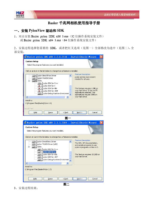
Basler千兆网相机使用指导手册一、安装PylonView驱动和SDK1、双击安装Basler_pylon_SDK_x86_3.exe(32位操作系统安装文件)或Basler_pylon_SDK_x64_3.exe(64位操作系统安装文件)2、安装过程选择您需要的SDK,或者把红叉选项(见图一)全部修改为选中(见图二),全部安装;图一图二3、安装过程结束;二、网络连接与相机IP地址设置1、摄像头:1个Basler千兆网相机2、测试板卡型号:1个支持巨帧功能的千兆网口3、修改网络连接IP地址步骤如下:3、双击电脑桌面上的Pylon IP Configuration Tool.exe,鼠标选中相机:设置IP准则:网络连接IP地址和相机的IP在一个网段,例如169.254.x.x或者192.168.x.x点击Chang Configuration,可以修改相机的Device User ID可以设定相机的名字,例如Camera1;修改相机IP地址为169.254.100.18,勾选上Use Persistent IP,不勾选Use DHCP设置IP准则:网络连接IP地址和相机的IP在一个网段,例如169.254.×.×IP地址的设置如下:网络连接IP/Mask Camera Network网络连接1IP169.254.100.18169.254.100.10 Mask255.255.0.0255.255.0.0三、千兆网高级属性设置1.主机优化设置关闭防火墙,包括系统自带的防火墙和自定义安装的防火墙。
2.采集系统优化设置设备管理器——网络适配器——“Intel(R)Pro/1000MT Desktop Adapter”属性——“高级”页(1)选择“巨帧(Jumbo Frames)”,设到可能的最大值(9k或16k);(2)选择“中断节流率(Maximum Interrupts Per Second)”,设为“极端;(3)选择“接收描述符(Receive Descriptors)”和“传输描述符(Transfer Descriptors)”,设为最大可能值;(4)选择“连接速度与双工模式”,设为1.0Gbps全双工;(非intel网卡);(5)非Intel的千兆网卡,以上几项参数请参照设置;选“确定”,关闭所有窗口。
basler相机设置详解

basler相机设置详解
请按如下顺序设置相机IP:一、确定与相机连接的网卡(1G速率)
二、设定网卡IP:
IP工具启动后的界面:
按IP工具中右上角第2个按钮“Change Configuration”后弹出对话框
修改相机IP地址“10.114.44.70”与子码掩码“255.255.255.0”,确认。
对话框确认后的画面:
按右上角第3个按钮“Write Configuration”
得到下图:注意红圈内的内容错误:
再次修改:
注意三个红圈中,左下的那个,就是上次“Write Configuration”时错误的那个。
达到这个状态后,再“Write Configuration”,就可以得到下面的状态:
三、检验上述完全正确IP——》
“10.114.44.XX”“10.114.44.YY”,子码掩码255.255.255.0。
四、正确后,启动另一个工具软件“Pylon
Viewer”
点击连续拍照(单次拍照也行),能得到图片即为正常。
设置结束。
如何修改摄像机IP网段
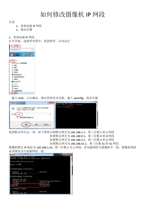
如何修改摄像机IP网段
目录
1、查询电脑IP网段
2、修改步骤
1、查询电脑IP网段
打开开始,选择所有程序,找到附件,启动运行
输入cmd,点击确定,弹出管理员对话框,输入ipconfig,按回车键
找到默认网关这一项,如下图所示例默认网关为192.168.1.1,第三位数1即1网段
如果默认网关为192.168.0.1,第三位数0即0网段
如果默认网关为192.168.2.1,第三位数2即2网段
如果默认网关为192.168.31.1,第三位数31即31网段
摄像机默认IP地址为192.168.1.10,第三位数1为1网段,若电脑网段与摄像机不一致,摄像机网段必须修改为与电脑网段一致
2、修改步骤
比如电脑网关是192.168.0.1,选择192.168.1.128,点击下面
IP地址修改为192.168.0.128
子网掩码不变255.255.255.0
网关修改为192.168.0.1
DNS不做任何变动再点击修改,便可访问网页了。
Baumer_BGAPI2

Baumer千兆网相机入门使用指南打开之后如下图所示,请点击Next1.接着点击选择同意License许可,并点击Next,如下图所示:2.完成上一步的操作之后,请选择Complete,也可以选择Typical或者Customized,并点击Next进入入下一步:3.在等待一段时间完成安装之后,会出现如下界面:请选择是否立刻启动Baumer相机的采图演示软件,然后点击Finish;此处建议不要直接打开该软件,因为后面还有很多准备事项是要在采图之前完成的;一、安装Baumer Filter Driver在状态栏的网络连接上右键打开网络和共享中心点击更改适配器设置选择一个连接相机的本地连接* 右键属性网络属性页中,如下图所示;点击Baumer Filter Driver会看到下面的描述部分,如图中的“”※注Filter Driver请直接按照该步骤以后的操作进行;请点击Install,然后会等待一段时间完成安装;4.完成安装以后会有如下界面显示,如果您想将驱动应用到具体某个网口上,请勾选要加载的网口,并点击Apply,如果要应用到您电脑上所有的网口,请直接关闭该软件:※注:上面讲了Baumer Filter Driver的安装过程,那究竟这个Baumer Filter Driver是干什么的呢?我们都知道,一般的网卡,微软的Windows系统安装之后在都会安装网卡的驱动,因此驱动已经安装了,为什么还要安装这个Baumer Filter Driver,实际上Baumer Filter Driver完整意义上并不是网卡的驱动,只是Baumer为了降低在使用Baumer千兆网相机的时候使用的电脑的CPU的负载率而专门研发的,将其加载到对应链接的网口;这在使用多相机的时候优势将比不安装这个驱动体现的更明显;5.验证当前驱动的版本是否正确,按照该章节步骤1的操作,打开网络连接--本地连接的网络属性,如下图所示:三、网卡的配置选项的设置1. 在“设备管理器”中找到“网络适配器”选项,如下图所示:2.选择一个您相机将要链接的一个网口,“右键”--“属性”,并选择|“高级”属性页,并找到“巨帧数据包”选项,然后在右边的选项中选择支持的最大巨帧数据包(9014字节或1602字节):如下图所示:3.打开“性能选项”的配置页面,需要配置的选项有下面所述的几项,如下图所示:① DMA结合:设置---禁用②传输缓冲区:设置---最大值(一般为2018)③传输延迟中断:设置---默认状态不需要设置④接收缓冲区:设置---最大值(一般为2018)⑤流量控制:设置---禁用⑥中断节流率:设置---极值※注:如果安装的没有安装网卡的随带网卡驱动,“性能选项”中的各个配置选项可能就直接散落在“高级”的唯一属性设置中,并且没有“性能选项”这个可配置项,那么只需要找到其中的各个配置项做好设置即可;四、相机的IP地址设置1.设置网络的IP地址,电脑桌面右下角“网络连接”---右键---“打开网络和共享中心”---“更改适配器设置”,如下图所示:2.然后,“本地连接”---右键---“属性”,在网络属性页中双击“Internet 协议版本4(TCP/IPv4)”选项,如下图所示:3.修改修改相机对应连接网络的IP地址,修改“自动获得IP地址(0)”为“使用下面的IP 地址(s)”,在“IP地址(I)”在“子网掩码(U)”4.在网络IP地址设置好之后,接下来设置相机的IP地址,使相机的IP地址和网络的IP地址在同一网段,否则将无法完成正确的数据传输;1)首先,打开Baumer提供的IP配置工具,打开前面提到的安装好Baumer开发包以后,打开桌面上的Baumer Camera Explorer (64 Bit),打开右下角的IP Congig-Tool,如下图所示:2)打开IPConfigTool之后,显示如下的页面,从中我们可以得到的一些信息,下面逐一说明:①当前相机的IP状态,如图中所示,当前相机的IP地址和设定的IP地址并不在一个网段;②用来强制转换相机的IP地址与网络的IP地址在同一网段,该操作是自动执行的,如果发现IP地址不正确,如上图1中所示,则点击ForceIP,如果有多台相机同时链接,选择点击Force-IP all;③该处显示本台电脑上链接的相机的详细信息,包含相机的型号名称,相机的SN,如果相机的IP地址和网络IP地址不在同一网段,字体将是蓝色的,如果IP地址在同一网段,字体为黑色,此时Force-IP,和Force-IP all按钮不会出现;④该处显示与相机链接的网络IP地址和子网掩码;⑤该处用来固定相机的IP地址为特定的值;上面提到的Force-IP只能将本次强制转换的相机IP地址保留到相机断电之前,如果相机断电之后,相机的IP地址将再次回到Force-IP之前的状态,因此此处的固定IP就尤为重要,这个部分操作将永久写入一个相机的IP地址,即使断点以后也可以永久保留;⑥给相机定重新定义一个用户定义名称,在用第三方软件取图的时候这个用户定义名称将比较重要;⑧在点击选中上面3中提到的相机,将会显示与相机相关的一些信息,包含相机的IP地址,子网掩码,与相机链接的网络IP地址,子网掩码等信息;3)Force-IP,强制装换相机的IP地址使其与网络IP地址在同一网段,如下图所示:Force-IP之后,在Available Camera中会显示黑色字体的相机信息,这时候表明相机的IP地址已经被强制转换成跟网络IP地址在同一网段了;4)固定相机的IP地址为永久IP,直到下次再次使用固定IP地址为另一个IP地址为止,如下图所示:在Force-IP之后,在Available Camera点击显示的相机,会在整个界面如2)中所示部分显示相机接口等的一些信息;请在Config Options中勾选LLA和Persistent IP来固定相机的IP地址,DHCP勾掉;然后在下面Persistent IP里面手动输入固定到相机内部的IP地址和子网掩码;这个IP地址可以根据Force-IP地址之后的Camera information中的IP address和Subnet mark后面的数据直接输入即可;到此为止相机,网络的设置都完成了,接下来可以操作软件来采图了;五、图像采集软件1.在完成IP配置之后,关掉IP ConfigTool,检测相机,双击检测到的相机,显示如下图所示:2.在右边的部分是相机某些参数的设置,你可以根据Profile的等级来操作相机参数的调节:其中Basic是最基本的操作,包含曝光,增益,帧率相关设置,连续图像的保存;Beginner,Expert,Guru等级逐一提高,意味着选择该档的面向客户开放的操作参数越高,需要客户的专业知识也越多;上面是通过安装一步一步来操作的,您也可以直接安装驱动,然后使用免安装的软件来完成相机的IP配置,采图软件的使用等;①驱动安装软件的目录为:Win32系统目录为:Win64系统目录为:②IP配置工具所在目录为:③Baumer-GAPI Exporer软件所在目录为:Win32系统目录为:Win64系统目录为:。
