Cisco MPLS-TE 配置实例
cisco交换机配置实例教程.doc

cisco交换机配置实例教程cisco交换机配置实例教程1、在交换机上启动QOSSwitch(config)#mls qos //在交换机上启动QOS2、分别定义PC1(10.10.1.1)和PC2(10.10.2.1)访问控制列表Switch(config)#access-list 10 permit 10.10.1.0 0.0.0.255 //控制pc1上行流量Switch(config)#access-list 100 permit any 10.10.1.0 0.0.0.255 //控制pc1下行流量Switch(config)#access-list 11 permit 10.10.2.0 0.0.0.255 //控制pc2上行流量Switch(config)#access-list 111 permit any 10.10.2.0 0.0.0.255 //控制pc2下行流量class-map mach-all {name}match access-group 110policy-mapclass二、详细配置过程注:每个接口每个方向只支持一个策略;一个策略可以用于多个接口。
因此所有PC的下载速率的限制都应该定义在同一个策略(在本例子当中为policy-map user-down),而PC不同速率的区分是在Class-map 分别定义。
1、在交换机上启动QOSSwitch(config)#mls qos //在交换机上启动QOS2、分别定义PC1(10.10.1.1)和PC2(10.10.2.1)访问控制列表Switch(config)#access-list 10 permit 10.10.1.0 0.0.0.255 //控制pc1上行流量Switch(config)#access-list 100 permit any 10.10.1.0 0.0.0.255 //控制pc1下行流量Switch(config)#access-list 11 permit 10.10.2.0 0.0.0.255 //控制pc2上行流量Switch(config)#access-list 111 permit any 10.10.2.0 0.0.0.255 //控制pc2下行流量3、定义类,并和上面定义的访问控制列表绑定Switch(config)# class-map user1-up //定义PC1上行的类,并绑定访问列表10Switch(config-cmap)# match access-group 10Switch(config-cmap)# exitSwitch(config)# class-map user2-upSwitch(config-cmap)# match access-group 11 //定义PC2上行的类,并绑定访问列表10Switch(config-cmap)# exitSwitch(config)# class-map user1-downSwitch(config-cmap)# match access-group 100 //定义PC1下行的类,并绑定访问列表100Switch(config-cmap)# exitSwitch(config)# class-map user2-downSwitch(config-cmap)# match access-group 111 //定义PC2下行的类,并绑定访问列表111Switch(config-cmap)# exit4、定义策略,把上面定义的类绑定到该策略Switch(config)# policy-map user1-up //定义PC1上行的速率为1MSwitch(config-pmap)# class user1-upSwitch(config-pmap-c)# trust dscpSwitch(config-pmap-c)# police 1024000 1024000 exceed-action dropSwitch(config)# policy-map user2-up //定义PC2上行的速率为2MSwitch(config-pmap)# class user2-upSwitch(config-pmap-c)# trust dscpSwitch(config-pmap-c)# police 2048000 1024000 exceed-action dropSwitch(config)# policy-map user-downSwitch(config-pmap)# class user1-downSwitch(config-pmap-c)# trust dscpSwitch(config-pmap-c)# police 1024000 1024000 exceed-action dropSwitch(config-pmap-c)# exitSwitch(config-pmap)# class user2-downSwitch(config-pmap-c)# trust dscpSwitch(config-pmap-c)# police 2048000 1024000 exceed-action dropSwitch(config-pmap-c)# exit5、在接口上运用策略Switch(config)# interface f0/1Switch(config-if)# service-policy input user1-upSwitch(config)# interface f0/2Switch(config-if)# service-policy input user2-upSwitch(config)# interface g0/1Switch(config-if)# service-policy input user-down看了cisco交换机配置实例教程还想看:1.思科交换机基本配置实例讲解2.CISCO交换机配置操作学习教程3.思科交换机配置教程详解4.cisco交换机qos配置实例教程5.思科路由器、交换机的基本管理教程6.Cisco 2960交换机的基础安装配置教程Cisco交换机入门配置的方法Cisco交换机入门配置的方法:机型:Cisco 3750想对交换机警醒配置。
Cisco路由器配置实例(经典)
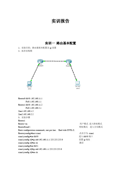
实训报告实训一路由基本配置1、实验目的:路由器基本配置及ip设置2、拓扑结构图Router0 fa0/0: 192.168.11.1Fa0/1:192.168.1.1Router1 fa0/0: 192.168.11.2Fa0/1:192.168.2.1Znn1:192.168.1.2Znn2:192.168.2.23、实验步骤Router1Router>en 用户模式进入特权模式Router#conf t 特权模式进入全局模式Enter configuration commands, one per line. End with CNTL/Z.Router(config)#host rznn1 改名字为rznn1rznn1(config)#int fa0/0 进入fa0/0端口rznn1(config-if)#ip add 192.168.11.1 255.255.255.0 设置ip地址rznn1(config-if)#no sh 激活rznn1(config)#int fa0/1rznn1(config-if)#ip add 192.168.1.1 255.255.255.0rznn1(config-if)#no shrznn1(config-if)#exitrznn1(config)#exitrznn1#copy running-config startup-config 保存Destination filename [startup-config]? startup-configrznn1#conf trznn1(config)#enable secret password 222 设置密文rznn1#show ip interface b 显示Interface IP-Address OK? Method Status Protocol FastEthernet0/0 192.168.11.1 YES manual up up FastEthernet0/1 192.168.1.1 YES manual up upVlan1 unassigned YES manual administratively down downrouter 2outer>enRouter#conf tEnter configuration commands, one per line. End with CNTL/Z.Router(config)#host rznn2rznn2(config)#int fa0/0rznn2(config-if)#ip add 192.168.11.2 255.255.255.0rznn2(config-if)#no shrznn2(config)#int fa0/1rznn2(config-if)#ip add 192.168.2.1 255.255.255.0rznn2(config-if)#no shRznn2#copy running-config startup-config 保存Destination filename [startup-config]? startup-configrznn2(config-if)#exitrznn2(config)#exitrznn2#conf trznn2(config)#enable secret 222rznn2#show ip interface bInterface IP-Address OK? Method Status Protocol FastEthernet0/0 192.168.11.2 YES manual up up FastEthernet0/1 192.168.2.1 YES manual up upVlan1 unassigned YES manual administratively down down实训二1、远程登录、密码设置及验证为路由器开设telnet端口,PC机可以远程登陆到Rznn3(Router 1)拓扑结构图Router0:192.168.1.1Pc:192.168.1.2步骤rznn3>rznn3>enrznn3#conf tEnter configuration commands, one per line. End with CNTL/Z.rznn3(config)#no ip domain lookuprznn3(config)#line cons 0rznn3(config-line)#password znnrznn3(config-line)#loginrznn3(config-line)#no exec-trznn3(config-line)#logg syncrznn3(config-line)#exitrznn3(config)#int fa0/0rznn3(config-if)#ip add 192.168.1.1 255.255.255.0rznn3(config-if)#no shrznn3(config-if)#exitrznn3(config)#line vty 0 4 打通五个端口rznn3(config-line)#password cisco 设置密码rznn3(config-line)#login 保存rznn3(config-line)#exit4、测试:实训三命令组1、目的:八条命令(no ip domain lookup\line cons 0\password\login\no exec-t\logg sync\show version\reload\copy running-config startup-config)\show cdp neighbors)2、拓扑结构图Router0 fa0/0: 192.168.11.1Router1 fa0/0: 192.168.11.23、步骤rznn1#conf tEnter configuration commands, one per line. End with CNTL/Z.1、rznn1(config)#no ip domain lookup 取消域名查找转换2、rznn1(config)#line cons 0 打开cons 0端口3、rznn1(config-line)#password znn 设置密码为znnrznn1(config-line)#login 保存rznn1(config-line)#no exec-t 设置永不超时4、rznn1(config-line)#logg sync 产生日志5、rznn1#show version 显示思科路由系统版本信息Cisco IOS Software, 2800 Software (C2800NM-ADVIPSERVICESK9-M), Version 12.4(15)T1, RELEASE SOFTWARE (fc2)Technical Support: /techsupportCopyright (c) 1986-2007 by Cisco Systems, Inc.Compiled Wed 18-Jul-07 06:21 by pt_rel_team6、rznn1#show cdp neighbors 查看路由器连接的相邻路由器的相关信息Capability Codes: R - Router, T - Trans Bridge, B - Source Route BridgeS - Switch, H - Host, I - IGMP, r - Repeater, P - PhoneDevice ID Local Intrfce Holdtme Capability Platform Port IDrznn2 Fas 0/0 139 R C2800 Fas 0/07、rznn1#copy running-config startup-config 保存刚才指令Destination filename [startup-config]? startup-configBuilding configuration...[OK]8、rznn1#reload 重启路由器Proceed with reload? [confirm]System Bootstrap, Version 12.1(3r)T2, RELEASE SOFTWARE (fc1)Copyright (c) 2000 by cisco Systems, Inc.cisco 2811 (MPC860) processor (revision 0x200) with 60416K/5120K bytes of memorySelf decompressing the image :########################################################################## [OK] Restricted Rights Legendrznn1#show ip interface bInterface IP-Address OK? Method Status Protocol FastEthernet0/0 192.168.11.1 YES manual up up FastEthernet0/1 192.168.1.1 YES manual up upVlan1 unassigned YES manual administratively down down9、rznn1(config-if)#ip add 192.168.3.1 255.255.255.0 重置ip地址rznn1#show ip interface bInterface IP-Address OK? Method Status Protocol FastEthernet0/0 192.168.3.1 YES manual up up FastEthernet0/1 192.168.1.1 YES manual up up Vlan1 unassigned YES manual administratively down down实训四发现协议1、实训目的通过发现协议显示路由器相邻路由的端口信息2、拓扑结构Router0:192.168.11.1Router1:fa0/0 192.168.11.2Fa0/1 192.168.12.1Router2:192.168.12.23、步骤R1路由器Router>enRouter#conf tEnter configuration commands, one per line. End with CNTL/Z.Router(config)#host r1r1(config)#int fa0/0r1(config-if)#ip add 192.168.11.1 255.255.255.0r1(config-if)#no sh%LINK-5-CHANGED: Interface FastEthernet0/0, changed state to upr1(config-if)#r1(config-if)#exitr1(config)#exitr1#%SYS-5-CONFIG_I: Configured from console by consoler1#show ip interface bInterface IP-Address OK? Method Status Protocol FastEthernet0/0 192.168.11.1 YES manual up down FastEthernet0/1 unassigned YES manual administratively down downVlan1 unassigned YES manual administratively down downR2 路由器Router>enRouter#conf tEnter configuration commands, one per line. End with CNTL/Z.Router(config)#host r2r2(config)#int fa0/0r2(config-if)#ip add 192.168.11.2 255.255.255.0r2(config-if)#no sh%LINK-5-CHANGED: Interface FastEthernet0/0, changed state to up%LINEPROTO-5-UPDOWN: Line protocol on Interface FastEthernet0/0, changed state to up r2(config-if)#exitr2(config)#exitr2#%SYS-5-CONFIG_I: Configured from console by consoler2#conf tEnter configuration commands, one per line. End with CNTL/Z.r2(config)#int fa0/0r2(config-if)#int fa0/1r2(config-if)#ip add 192.168.12.1 255.255.255.0r2(config-if)#no sh%LINK-5-CHANGED: Interface FastEthernet0/1, changed state to upr2(config-if)#exitr2(config)#exitr2#%SYS-5-CONFIG_I: Configured from console by consoler2#show ip interface bInterface IP-Address OK? Method Status Protocol FastEthernet0/0 192.168.11.2 YES manual up upFastEthernet0/1 192.168.12.1 YES manual up down Vlan1 unassigned YES manual administratively down downR3路由器Router>enRouter#conf tEnter configuration commands, one per line. End with CNTL/Z.Router(config)#host r3r3(config)#int fa0/0r3(config-if)#ip add 192.168.12.2 255.255.255.0r3(config-if)#no sh%LINK-5-CHANGED: Interface FastEthernet0/0, changed state to up%LINEPROTO-5-UPDOWN: Line protocol on Interface FastEthernet0/0, changed state to up r3(config-if)#exitr3(config)#exitr3#%SYS-5-CONFIG_I: Configured from console by consoler3#show ip interface bInterface IP-Address OK? Method Status Protocol FastEthernet0/0 192.168.12.2 YES manual up up FastEthernet0/1 unassigned YES manual administratively down downVlan1 unassigned YES manual administratively down downR1发现邻居r1#show cdp neighborsCapability Codes: R - Router, T - Trans Bridge, B - Source Route BridgeS - Switch, H - Host, I - IGMP, r - Repeater, P - PhoneDevice ID Local Intrfce Holdtme Capability Platform Port IDr2 Fas 0/0 165 R C2800 Fas 0/0R2发现邻居r2#show cdp neighborsCapability Codes: R - Router, T - Trans Bridge, B - Source Route BridgeS - Switch, H - Host, I - IGMP, r - Repeater, P - PhoneDevice ID Local Intrfce Holdtme Capability Platform Port IDr1 Fas 0/0 176 R C1841 Fas 0/0r3 Fas 0/1 130 R C1841 Fas 0/0R3发现邻居r3#show cdp neighborsCapability Codes: R - Router, T - Trans Bridge, B - Source Route BridgeS - Switch, H - Host, I - IGMP, r - Repeater, P - PhoneDevice ID Local Intrfce Holdtme Capability Platform Port IDr2 Fas 0/0 166 R C2800 Fas 0/14、总结show 命令(1)show ip interface b (显示端口ip信息)(2)show version (显示ios版本信息)(3)show running-config (显示刚才使用的命令配置信息)(4)show cdp neighbors (显示发现邻居直连设备信息)(5)show interface (显示所有端口详细信息)实训五静态路由1、实验目的:将不同网段的网络配通(ip route)Ip route语法:ip route 目标地址子网掩码相邻路由器接口地址Show ip route2、试验拓扑:Router0:192.168.11.1Router1:fa0/0 192.168.11.2Fa0/1 192.168.12.1Router2:192.168.12.23、实验步骤:Router1Router>enRouter#conf tRouter(config)#host r1r1(config)#int fa0/0r1(config-if)#ip add 192.168.11.1 255.255.255.0r1(config-if)#no sh%LINK-5-CHANGED: Interface FastEthernet0/0, changed state to upr1(config-if)#exitr1(config)#exitr1#show ip interface bInterface IP-Address OK? Method Status ProtocolFastEthernet0/0 192.168.11.1 YES manual up downFastEthernet0/1 unassigned YES manual administratively down downVlan1 unassigned YES manual administratively down downr1#%LINEPROTO-5-UPDOWN: Line protocol on Interface FastEthernet0/0, changed state to up r1#ping 192.168.12.1Type escape sequence to abort.Sending 5, 100-byte ICMP Echos to 192.168.12.1, timeout is 2 seconds:.....Success rate is 0 percent (0/5)r1#conf tEnter configuration commands, one per line. End with CNTL/Z.r1(config)#ip route 192.168.12.0 255.255.255.0 192.168.11.2r1(config)#exitr1#ping 192.168.12.1Type escape sequence to abort.Sending 5, 100-byte ICMP Echos to 192.168.12.1, timeout is 2 seconds:Success rate is 100 percent (5/5), round-trip min/avg/max = 31/31/32 msr1#ping 192.168.12.2Type escape sequence to abort.Sending 5, 100-byte ICMP Echos to 192.168.12.2, timeout is 2 seconds:.....Success rate is 0 percent (0/5)r1#ping 192.168.12.2Type escape sequence to abort.Sending 5, 100-byte ICMP Echos to 192.168.12.2, timeout is 2 seconds:Success rate is 100 percent (5/5), round-trip min/avg/max = 47/62/78 msr1#show ip routeCodes: C - connected, S - static, I - IGRP, R - RIP, M - mobile, B - BGPD - EIGRP, EX - EIGRP external, O - OSPF, IA - OSPF inter areaN1 - OSPF NSSA external type 1, N2 - OSPF NSSA external type 2E1 - OSPF external type 1, E2 - OSPF external type 2, E - EGPi - IS-IS, L1 - IS-IS level-1, L2 - IS-IS level-2, ia - IS-IS inter area* - candidate default, U - per-user static route, o - ODRP - periodic downloaded static routeGateway of last resort is not setC 192.168.11.0/24 is directly connected, FastEthernet0/0S 192.168.12.0/24 [1/0] via 192.168.11.2Router3Router>enRouter#conf tEnter configuration commands, one per line. End with CNTL/Z.Router(config)#host r3r3(config)#int fa0/0r3(config-if)#ip add 192.168.12.2 255.255.255.0r3(config-if)#no sh%LINK-5-CHANGED: Interface FastEthernet0/0, changed state to up%LINEPROTO-5-UPDOWN: Line protocol on Interface FastEthernet0/0, changed state to up r3(config-if)#exitr3(config)#exitr3#%SYS-5-CONFIG_I: Configured from console by consoler3#show ip interface bInterface IP-Address OK? Method Status Protocol FastEthernet0/0 192.168.12.2 YES manual up up FastEthernet0/1 unassigned YES manual administratively down downVlan1 unassigned YES manual administratively down downr3#conf tEnter configuration commands, one per line. End with CNTL/Z.r3(config)#ip route 192.168.11.0 255.255.255.0 192.168.12.1r3(config)#exitr3#ping 192.168.11.2Type escape sequence to abort.Sending 5, 100-byte ICMP Echos to 192.168.11.2, timeout is 2 seconds:Success rate is 100 percent (5/5), round-trip min/avg/max = 31/31/32 msr3#ping 192.168.11.1Type escape sequence to abort.Sending 5, 100-byte ICMP Echos to 192.168.11.1, timeout is 2 seconds:Success rate is 100 percent (5/5), round-trip min/avg/max = 62/62/63 msr3#show ip routeCodes: C - connected, S - static, I - IGRP, R - RIP, M - mobile, B - BGPD - EIGRP, EX - EIGRP external, O - OSPF, IA - OSPF inter areaN1 - OSPF NSSA external type 1, N2 - OSPF NSSA external type 2i - IS-IS, L1 - IS-IS level-1, L2 - IS-IS level-2, ia - IS-IS inter area* - candidate default, U - per-user static route, o - ODRP - periodic downloaded static routeGateway of last resort is not setS 192.168.11.0/24 [1/0] via 192.168.12.1C 192.168.12.0/24 is directly connected, FastEthernet0/04、默认路由Route 1r1>enr1#conf tEnter configuration commands, one per line. End with CNTL/Z.r1(config)#no ip route 192.168.12.0 255.255.255.0 192.168.11.2%No matching route to deleter1(config)#exitr1#%SYS-5-CONFIG_I: Configured from console by consoler1#show ip routeCodes: C - connected, S - static, I - IGRP, R - RIP, M - mobile, B - BGPD - EIGRP, EX - EIGRP external, O - OSPF, IA - OSPF inter areaN1 - OSPF NSSA external type 1, N2 - OSPF NSSA external type 2E1 - OSPF external type 1, E2 - OSPF external type 2, E - EGPi - IS-IS, L1 - IS-IS level-1, L2 - IS-IS level-2, ia - IS-IS inter area* - candidate default, U - per-user static route, o - ODRP - periodic downloaded static routeGateway of last resort is not setC 192.168.11.0/24 is directly connected, FastEthernet0/0r1#conf tEnter configuration commands, one per line. End with CNTL/Z.r1(config)#ip route 0.0.0.0 0.0.0.0 192.168.11.2r1(config)#exitr1#%SYS-5-CONFIG_I: Configured from console by consoler1#show ip routeCodes: C - connected, S - static, I - IGRP, R - RIP, M - mobile, B - BGPD - EIGRP, EX - EIGRP external, O - OSPF, IA - OSPF inter areaN1 - OSPF NSSA external type 1, N2 - OSPF NSSA external type 2i - IS-IS, L1 - IS-IS level-1, L2 - IS-IS level-2, ia - IS-IS inter area* - candidate default, U - per-user static route, o - ODRP - periodic downloaded static routeGateway of last resort is 192.168.11.2 to network 0.0.0.0C 192.168.11.0/24 is directly connected, FastEthernet0/0S* 0.0.0.0/0 [1/0] via 192.168.11.2r1#ping 192.168.12.1Type escape sequence to abort.Sending 5, 100-byte ICMP Echos to 192.168.12.1, timeout is 2 seconds:Success rate is 100 percent (5/5), round-trip min/avg/max = 16/28/31 msr1#ping 192.168.12.2Type escape sequence to abort.Sending 5, 100-byte ICMP Echos to 192.168.12.2, timeout is 2 seconds: Success rate is 100 percent (5/5), round-trip min/avg/max = 62/62/63 msRoute 3r1>enr1#conf tEnter configuration commands, one per line. End with CNTL/Z.r1(config)#no ip route 192.168.12.0 255.255.255.0 192.168.11.2%No matching route to deleter1(config)#exitr1#%SYS-5-CONFIG_I: Configured from console by consoler1#show ip routeCodes: C - connected, S - static, I - IGRP, R - RIP, M - mobile, B - BGPD - EIGRP, EX - EIGRP external, O - OSPF, IA - OSPF inter areaN1 - OSPF NSSA external type 1, N2 - OSPF NSSA external type 2E1 - OSPF external type 1, E2 - OSPF external type 2, E - EGPi - IS-IS, L1 - IS-IS level-1, L2 - IS-IS level-2, ia - IS-IS inter area* - candidate default, U - per-user static route, o - ODRP - periodic downloaded static routeGateway of last resort is not setC 192.168.11.0/24 is directly connected, FastEthernet0/0r1#conf tEnter configuration commands, one per line. End with CNTL/Z.r1(config)#ip route 0.0.0.0 0.0.0.0 192.168.11.2r1(config)#exitr1#%SYS-5-CONFIG_I: Configured from console by consoler1#show ip routeCodes: C - connected, S - static, I - IGRP, R - RIP, M - mobile, B - BGPD - EIGRP, EX - EIGRP external, O - OSPF, IA - OSPF inter areaN1 - OSPF NSSA external type 1, N2 - OSPF NSSA external type 2E1 - OSPF external type 1, E2 - OSPF external type 2, E - EGPi - IS-IS, L1 - IS-IS level-1, L2 - IS-IS level-2, ia - IS-IS inter area* - candidate default, U - per-user static route, o - ODRP - periodic downloaded static routeGateway of last resort is 192.168.11.2 to network 0.0.0.0C 192.168.11.0/24 is directly connected, FastEthernet0/0S* 0.0.0.0/0 [1/0] via 192.168.11.2r3#ping 192.168.11.1Type escape sequence to abort.Sending 5, 100-byte ICMP Echos to 192.168.11.1, timeout is 2 seconds: Success rate is 100 percent (5/5), round-trip min/avg/max = 62/62/63 ms实训六动态路由RIP 协议1、实验目的使用配置动态路由启动Rip协议使用到的命令(router rip/network/show ip protocols/show ip route)2、实验拓扑R1 fa0/0 192.168.11.1R2 fa0/0 192.168.11.2fa0/1 192.168.12.1R3 fa0/0 192.168.12.23、实验步骤R1Router>enRouter#conf tEnter configuration commands, one per line. End with CNTL/Z. Router(config)#host r1r1(config)#int fa0/0r1(config-if)#ip add 192.168.11.1 255.255.255.0r1(config-if)#no shr1(config-if)#exitr1(config)#router ripr1(config-router)#network 192.168.11.0r1(config-router)#exitr1(config)#exitr1#%SYS-5-CONFIG_I: Configured from console by consoleR2Router>enRouter#conf tEnter configuration commands, one per line. End with CNTL/Z. Router(config)#host r2r2(config)#int fa0/0r2(config-if)#ip add 192.168.11.2 255.255.255.0r2(config-if)#no shr2(config-if)#exitr2(config)#int fa0/1r2(config-if)#ip add 192.168.12.1 255.255.255.0r2(config-if)#no shr2(config-if)#exitr2(config)#router ripr2(config-router)#network 192.168.11.0r2(config-router)#network 192.168.12.0r2(config-router)#exitr2(config)#exitr2#R3Router>enRouter#conf tEnter configuration commands, one per line. End with CNTL/Z. Router(config)#host r3r3(config)#int fa0/0r3(config-if)#ip add 192.168.12.2 255.255.255.0r3(config-if)#no shr3(config-if)#exitr3(config)#router ripr3(config-router)#network 192.168.12.0r3(config-router)#exitr3(config)#exitr3#%SYS-5-CONFIG_I: Configured from console by console4、实验测试R1r1#show ip protocolsRouting Protocol is "rip"Sending updates every 30 seconds, next due in 10 secondsInvalid after 180 seconds, hold down 180, flushed after 240 Outgoing update filter list for all interfaces is not setIncoming update filter list for all interfaces is not set Redistributing: ripDefault version control: send version 1, receive any version Interface Send Recv Triggered RIP Key-chain FastEthernet0/0 1 2 1Automatic network summarization is in effectMaximum path: 4Routing for Networks:192.168.11.0Passive Interface(s):Routing Information Sources:Gateway Distance Last UpdateDistance: (default is 120)r1#show ip routeCodes: C - connected, S - static, I - IGRP, R - RIP, M - mobile, B - BGPD - EIGRP, EX - EIGRP external, O - OSPF, IA - OSPF inter areaN1 - OSPF NSSA external type 1, N2 - OSPF NSSA external type 2E1 - OSPF external type 1, E2 - OSPF external type 2, E - EGPi - IS-IS, L1 - IS-IS level-1, L2 - IS-IS level-2, ia - IS-IS inter area* - candidate default, U - per-user static route, o - ODRP - periodic downloaded static routeGateway of last resort is not setC 192.168.11.0/24 is directly connected, FastEthernet0/0R 192.168.12.0/24 [120/1] via 192.168.11.2, 00:00:24, FastEthernet0/0 r1#ping 192.168.12.0Type escape sequence to abort.Sending 5, 100-byte ICMP Echos to 192.168.12.0, timeout is 2 seconds: Success rate is 100 percent (5/5), round-trip min/avg/max = 31/31/32 msR2r2#show ip protocolsRouting Protocol is "rip"Sending updates every 30 seconds, next due in 21 secondsInvalid after 180 seconds, hold down 180, flushed after 240Outgoing update filter list for all interfaces is not setIncoming update filter list for all interfaces is not setRedistributing: ripDefault version control: send version 1, receive any versionInterface Send Recv Triggered RIP Key-chain FastEthernet0/0 1 2 1FastEthernet0/1 1 2 1Automatic network summarization is in effectMaximum path: 4Routing for Networks:192.168.11.0192.168.12.0Passive Interface(s):Routing Information Sources:Gateway Distance Last UpdateDistance: (default is 120)r2#show ip routeCodes: C - connected, S - static, I - IGRP, R - RIP, M - mobile, B - BGPD - EIGRP, EX - EIGRP external, O - OSPF, IA - OSPF inter areaN1 - OSPF NSSA external type 1, N2 - OSPF NSSA external type 2E1 - OSPF external type 1, E2 - OSPF external type 2, E - EGPi - IS-IS, L1 - IS-IS level-1, L2 - IS-IS level-2, ia - IS-IS inter area* - candidate default, U - per-user static route, o - ODRP - periodic downloaded static routeGateway of last resort is not setC 192.168.11.0/24 is directly connected, FastEthernet0/0C 192.168.12.0/24 is directly connected, FastEthernet0/1R3r3#show ip protocolsRouting Protocol is "rip"Sending updates every 30 seconds, next due in 15 secondsInvalid after 180 seconds, hold down 180, flushed after 240Outgoing update filter list for all interfaces is not setIncoming update filter list for all interfaces is not setRedistributing: ripDefault version control: send version 1, receive any versionInterface Send Recv Triggered RIP Key-chain FastEthernet0/0 1 2 1Automatic network summarization is in effectMaximum path: 4Routing for Networks:192.168.12.0Passive Interface(s):Routing Information Sources:Gateway Distance Last UpdateDistance: (default is 120)r3#show ip routeCodes: C - connected, S - static, I - IGRP, R - RIP, M - mobile, B - BGPD - EIGRP, EX - EIGRP external, O - OSPF, IA - OSPF inter areaN1 - OSPF NSSA external type 1, N2 - OSPF NSSA external type 2E1 - OSPF external type 1, E2 - OSPF external type 2, E - EGPi - IS-IS, L1 - IS-IS level-1, L2 - IS-IS level-2, ia - IS-IS inter area* - candidate default, U - per-user static route, o - ODRP - periodic downloaded static routeGateway of last resort is not setR 192.168.11.0/24 [120/1] via 192.168.12.1, 00:00:04, FastEthernet0/0 C 192.168.12.0/24 is directly connected, FastEthernet0/0r3#ping 192.168.11.0Type escape sequence to abort.Sending 5, 100-byte ICMP Echos to 192.168.11.0, timeout is 2 seconds: Success rate is 100 percent (5/5), round-trip min/avg/max = 31/31/32 ms实训七负载平衡试训目的实现负载平衡实训拓扑R1 fa0/0 192.168.11.1R2 eth0/0/0 192.168.11.2Fa0/0 192.168.12.1Fa0/0 192.168.13.1R3 fa0/0 192.168.12.2Fa0/1 192.168.14.1R4 fa0/0 192.168.13.2Fa0/1 192.168.15.1R5 fa0/0 192.168.14.2Fa0/1 192.168.15.2实训步骤(R1 )r1>enR1#conf tR1(config)#ip route 0.0.0.0 0.0.0.0 192.168.11.2R1(config)#exitr1#show ip routeCodes: C - connected, S - static, I - IGRP, R - RIP, M - mobile, B - BGPD - EIGRP, EX - EIGRP external, O - OSPF, IA - OSPF inter areaN1 - OSPF NSSA external type 1, N2 - OSPF NSSA external type 2E1 - OSPF external type 1, E2 - OSPF external type 2, E - EGPi - IS-IS, L1 - IS-IS level-1, L2 - IS-IS level-2, ia - IS-IS inter area* - candidate default, U - per-user static route, o - ODRP - periodic downloaded static routeGateway of last resort is 192.168.11.2 to network 0.0.0.0C 192.168.11.0/24 is directly connected, FastEthernet0/0S* 0.0.0.0/0 [1/0] via 192.168.11.2(R2)r2>enr2(config)#ip route 0.0.0.0 0.0.0.0 192.168.12.2r2(config)#ip route 0.0.0.0 0.0.0.0 192.168.13.2r2(config)#exitr2#%SYS-5-CONFIG_I: Configured from console by consoles% Ambiguous command: "s"r2#show ip routeCodes: C - connected, S - static, I - IGRP, R - RIP, M - mobile, B - BGPD - EIGRP, EX - EIGRP external, O - OSPF, IA - OSPF inter areaN1 - OSPF NSSA external type 1, N2 - OSPF NSSA external type 2E1 - OSPF external type 1, E2 - OSPF external type 2, E - EGPi - IS-IS, L1 - IS-IS level-1, L2 - IS-IS level-2, ia - IS-IS inter area* - candidate default, U - per-user static route, o - ODRP - periodic downloaded static routeGateway of last resort is 192.168.12.2 to network 0.0.0.0C 192.168.11.0/24 is directly connected, Ethernet0/0/0C 192.168.12.0/24 is directly connected, FastEthernet0/0C 192.168.13.0/24 is directly connected, FastEthernet0/1S* 0.0.0.0/0 [1/0] via 192.168.12.2[1/0] via 192.168.13.2(R3)r3>enr3#conf tEnter configuration commands, one per line. End with CNTL/Z.r3(config)#ip route 0.0.0.0 0.0.0.0 192.168.12.1r3(config)#exitr3#%SYS-5-CONFIG_I: Configured from console by consoler3#show ip routeCodes: C - connected, S - static, I - IGRP, R - RIP, M - mobile, B - BGPD - EIGRP, EX - EIGRP external, O - OSPF, IA - OSPF inter areaN1 - OSPF NSSA external type 1, N2 - OSPF NSSA external type 2E1 - OSPF external type 1, E2 - OSPF external type 2, E - EGPi - IS-IS, L1 - IS-IS level-1, L2 - IS-IS level-2, ia - IS-IS inter area* - candidate default, U - per-user static route, o - ODRP - periodic downloaded static routeGateway of last resort is 192.168.12.1 to network 0.0.0.0C 192.168.12.0/24 is directly connected, FastEthernet0/0C 192.168.14.0/24 is directly connected, FastEthernet0/1S* 0.0.0.0/0 [1/0] via 192.168.12.1(R4)r4>enr4#conf tEnter configuration commands, one per line. End with CNTL/Z.r4(config)#ip route 0.0.0.0 0.0.0.0 192.168.13.1r4(config)#exitr4#%SYS-5-CONFIG_I: Configured from console by consoler4#show ip routeCodes: C - connected, S - static, I - IGRP, R - RIP, M - mobile, B - BGPD - EIGRP, EX - EIGRP external, O - OSPF, IA - OSPF inter areaN1 - OSPF NSSA external type 1, N2 - OSPF NSSA external type 2E1 - OSPF external type 1, E2 - OSPF external type 2, E - EGPi - IS-IS, L1 - IS-IS level-1, L2 - IS-IS level-2, ia - IS-IS inter area* - candidate default, U - per-user static route, o - ODRP - periodic downloaded static routeGateway of last resort is 192.168.13.1 to network 0.0.0.0C 192.168.13.0/24 is directly connected, FastEthernet0/0C 192.168.15.0/24 is directly connected, FastEthernet0/1S* 0.0.0.0/0 [1/0] via 192.168.13.1(R5)r5>enr5#conf tEnter configuration commands, one per line. End with CNTL/Z.r5(config)#ip route 0.0.0.0 0.0.0.0 192.168.14.1r5(config)#ip route 0.0.0.0 0.0.0.0 192.168.15.1r5(config)#exitr5#%SYS-5-CONFIG_I: Configured from console by consoler5#show ip routeCodes: C - connected, S - static, I - IGRP, R - RIP, M - mobile, B - BGPD - EIGRP, EX - EIGRP external, O - OSPF, IA - OSPF inter areaN1 - OSPF NSSA external type 1, N2 - OSPF NSSA external type 2E1 - OSPF external type 1, E2 - OSPF external type 2, E - EGPi - IS-IS, L1 - IS-IS level-1, L2 - IS-IS level-2, ia - IS-IS inter area* - candidate default, U - per-user static route, o - ODRP - periodic downloaded static routeGateway of last resort is 192.168.14.1 to network 0.0.0.0C 192.168.14.0/24 is directly connected, FastEthernet0/0C 192.168.15.0/24 is directly connected, FastEthernet0/1S* 0.0.0.0/0 [1/0] via 192.168.14.1[1/0] via 192.168.15.1实训测试(R1)r1#ping 192.168.14.1Type escape sequence to abort.Sending 5, 100-byte ICMP Echos to 192.168.14.1, timeout is 2 seconds:Success rate is 100 percent (5/5), round-trip min/avg/max = 62/84/94 ms (R5)r5#ping 192.168.11.1Type escape sequence to abort.Sending 5, 100-byte ICMP Echos to 192.168.11.1, timeout is 2 seconds: Success rate is 100 percent (5/5), round-trip min/avg/max = 79/91/94 ms实训八DHCP 协议配置实训目的全网配通实训拓扑Fa0/0 192.168.11.1Fa0/1 192.168.12.1实训步骤Router>enRouter#conf tEnter configuration commands, one per line. End with CNTL/Z.Router(config)#host r1r1(config)#int fa0/0r1(config-if)#ip add 192.168.11.1 255.255.255.0r1(config-if)#no shr1(config-if)#exitr1(config)#int fa0/1r1(config-if)#ip add 192.168.12.1 255.255.255.0r1(config-if)#no shr1(config-if)#exitr1(config)#ip dhcp pool znn //配置一个根地址池znnr1(dhcp-config)#network 192.168.11.0 255.255.255.0 //为所有客户机动态分配的地址段r1(dhcp-config)#default-router 192.168.11.1 //为客户机配置默认的网关r1(dhcp-config)#dns-server 192.168.11.1 //为客户机配置DNS服务器r1(dhcp-config)#exitr1(config)#ip dhcp pool znn1r1(dhcp-config)#network 192.168.12.0 255.255.255.0r1(dhcp-config)#default-router 192.168.12.1r1(dhcp-config)#dns-server 192.168.12.1r1(dhcp-config)#exit。
CISCO+OSPF+MPLS+BGP配置实例加讲解

CISCO 路由器OSPF+MPLS+BGP配置实例二OO八年九月四日目录一、网络环境 (3)二、网络描述 (3)三、网络拓扑图 (4)四、P路由器配置 (4)五、PE1路由器配置 (6)六、PE2路由器配置 (9)七、CE1路由器配置 (11)八、CE2路由器配置 (13)九、业务测试 (14)一、网络环境由5台CISCO7204组成的网络,一台为P路由器,两台PE路由器,两台CE 路由器;二、网络描述在P和两台PE路由器这间通过OSPF动态路由协议完成MPLS网络的建立,两台PE路由器这间启用BGP路由协议,在PE路由器上向所属的CE路由器指VPN 路由,在CE路由器中向PE路由器配置静态路由。
配置思路:1、在P和两台PE路由器这间通过OSPF动态路由协议,在P和PE路由器两两互连的端口上启用MPLS,两台PE之间的路为备份路由,这属公网路由。
2、两台PE路由器这间启用BGP路由协议,这使得属于VPN的IP地址能在两个网络(两台CE所属的网络)互相发布,这属私网(VPN)路由。
3、在PE路由器上向所属的CE路由器指VPN路由,这打通了两个网络(两台CE所属的网络)之间的路由。
三、网络拓扑图P路由器(r1)(r4) CE1路由器(r5)LOOP0:192.168.3.1/24LOOP0:192.168.4.1/24四、P路由器配置p#SHOW RUNBuilding configuration...Current configuration : 1172 bytes!version 12.3service timestamps debug datetime msecservice timestamps log datetime msecno service password-encryption!hostname p!boot-start-markerboot-end-marker!!no aaa new-modelip subnet-zero!!!ip cefip audit po max-events 100!!interface Loopback0ip address 202.98.4.3 255.255.255.255 !interface FastEthernet0/0description to_r2ip address 10.1.1.10 255.255.255.252 ip ospf cost 20duplex fulltag-switching mtu 1508tag-switching ip!interface FastEthernet1/0description to_r3ip address 10.1.1.6 255.255.255.252 ip ospf cost 20duplex fulltag-switching mtu 1508tag-switching ip!interface FastEthernet2/0no ip addressshutdownduplex half!interface FastEthernet3/0no ip addressshutdownduplex half!router ospf 100log-adjacency-changesredistribute connected subnets redistribute static subnetsnetwork 10.1.1.6 0.0.0.0 area 0 network 10.1.1.10 0.0.0.0 area 0!ip classlessno ip http serverno ip http secure-server!gatekeepershutdown!!line con 0exec-timeout 0 0logging synchronousstopbits 1line aux 0stopbits 1line vty 0 4login!!endp#五、PE1路由器配置pe1#show runBuilding configuration...Current configuration : 1813 bytes!version 12.3service timestamps debug datetime msec service timestamps log datetime msec no service password-encryption!hostname pe1!boot-start-markerboot-end-marker!!no aaa new-modelip subnet-zero!!!ip vrf vpnard 1:100route-target export 200:1route-target import 200:1!ip cefip audit po max-events 100!!interface Loopback0ip address 202.98.4.1 255.255.255.255!interface FastEthernet0/0description to_r5ip vrf forwarding vpnaip address 172.16.1.1 255.255.255.252 duplex fulltag-switching ip!interface FastEthernet1/0description to_r1ip address 10.1.1.5 255.255.255.252ip ospf cost 20duplex fulltag-switching mtu 1508tag-switching ip!interface FastEthernet2/0ip address 10.1.1.1 255.255.255.252ip ospf cost 100duplex fulltag-switching mtu 1508tag-switching ip!interface FastEthernet3/0no ip addressshutdownduplex half!router ospf 100log-adjacency-changesredistribute connected metric-type 1 subnetsnetwork 10.1.1.0 0.0.0.255 area 0network 202.98.4.0 0.0.0.255 area 0!router bgp 100no bgp default ipv4-unicastbgp log-neighbor-changesneighbor 202.98.4.2 remote-as 100neighbor 202.98.4.2 update-source Loopback0 neighbor 202.98.4.2 version 4!address-family vpnv4neighbor 202.98.4.2 activateneighbor 202.98.4.2 send-community extendedexit-address-family!address-family ipv4 vrf vpnaredistribute connectedredistribute staticno auto-summaryno synchronizationexit-address-family!ip classlessip route vrf vpna 192.168.3.0 255.255.255.0 172.16.1.2 no ip http serverno ip http secure-server!ip ospf name-lookup!!gatekeepershutdown!!line con 0exec-timeout 0 0logging synchronousstopbits 1line aux 0stopbits 1line vty 0 4login!!endpe1#六、PE2路由器配置pe2#show runBuilding configuration...Current configuration : 1725 bytes!version 12.3service timestamps debug datetime msec service timestamps log datetime msec no service password-encryption!hostname pe2!boot-start-markerboot-end-marker!!no aaa new-modelip subnet-zero!!!ip vrf vpnard 1:100route-target export 200:1route-target import 200:1!ip cefip audit po max-events 100!!interface Loopback0ip address 202.98.4.2 255.255.255.255 !interface FastEthernet0/0description to_r1ip address 10.1.1.9 255.255.255.252ip ospf cost 20duplex fulltag-switching ip!interface FastEthernet1/0ip vrf forwarding vpnaip address 172.16.2.1 255.255.255.0duplex fulltag-switching ip!interface FastEthernet2/0ip address 10.1.1.2 255.255.255.252ip ospf cost 100duplex fulltag-switching ip!interface FastEthernet3/0no ip addressshutdownduplex half!router ospf 100log-adjacency-changesredistribute connected metric 1 subnets redistribute static metric-type 1 subnets network 10.1.1.0 0.0.0.255 area 0!router bgp 100no bgp default ipv4-unicastbgp log-neighbor-changesneighbor 202.98.4.1 remote-as 100neighbor 202.98.4.1 update-source Loopback0 neighbor 202.98.4.1 version 4!address-family vpnv4neighbor 202.98.4.1 activateneighbor 202.98.4.1 send-community extended exit-address-family!address-family ipv4 vrf vpnaredistribute connectedredistribute staticno auto-summaryno synchronizationexit-address-family!ip classlessip route vrf vpna 192.168.4.0 255.255.255.0 172.16.2.2 no ip http serverno ip http secure-server!gatekeepershutdown!!line con 0exec-timeout 0 0logging synchronousstopbits 1line aux 0stopbits 1line vty 0 4login!!End七、CE1路由器配置ce1#show runBuilding configuration...Current configuration : 892 bytes!version 12.3service timestamps debug datetime msecservice timestamps log datetime msecno service password-encryption!hostname ce1!boot-start-markerboot-end-marker!!no aaa new-modelip subnet-zero!!!ip cefip audit po max-events 100!!interface Loopback0ip address 192.168.3.1 255.255.255.0 !interface FastEthernet0/0description to_r3ip address 172.16.1.2 255.255.255.252 duplex full!interface FastEthernet1/0no ip addressshutdownduplex half!interface FastEthernet2/0no ip addressshutdownduplex half!interface FastEthernet3/0no ip addressshutdownduplex half!ip classlessip route 0.0.0.0 0.0.0.0 172.16.1.1no ip http serverno ip http secure-server!!!gatekeepershutdown!!line con 0exec-timeout 0 0logging synchronousstopbits 1line aux 0stopbits 1line vty 0 4login!!end八、CE2路由器配置Ce2#show runBuilding configuration...*Sep 3 13:53:56.167: %SYS-5-CONFIG_I: Configured from console by console Current configuration : 888 bytes!version 12.3service timestamps debug datetime msecservice timestamps log datetime msecno service password-encryption!hostname ce2!boot-start-markerboot-end-marker!!no aaa new-modelip subnet-zero!!!ip cefip audit po max-events 100!!interface Loopback0ip address 10.10.13.1 255.255.255.0!interface FastEthernet0/0no ip addressshutdownduplex half!interface FastEthernet1/0description to_r2ip address 10.10.12.2 255.255.255.0duplex full!interface FastEthernet2/0no ip addressshutdownduplex half!interface FastEthernet3/0no ip addressshutdownduplex half!ip classlessip route 0.0.0.0 0.0.0.0 172.16.2.1no ip http serverno ip http secure-server!!gatekeepershutdown!!line con 0exec-timeout 0 0logging synchronousstopbits 1line aux 0stopbits 1line vty 0 4login!!end九、业务测试ce1# ping 172.16.1.1Type escape sequence to abort.Sending 5, 100-byte ICMP Echos to 172.16.1.1, timeout is 2 seconds:Success rate is 100 percent (5/5), round-trip min/avg/max = 96/190/324 ms ce1#ce2#ping 192.168.3.1Type escape sequence to abort.Sending 5, 100-byte ICMP Echos to 192.168.3.1, timeout is 2 seconds:Success rate is 100 percent (5/5), round-trip min/avg/max = 336/468/588 ms ce2#。
Cisco MPLS流量工程TE隧道的基本配置(整理)

1 流量工程简介TE:Traffic Engineering的缩写,即流量工程的意思。
流量工程的本质就是将业务流量映射到实际的物理路径上。
就MPLS而言,此中心思想就是按照网络的实际情况为数据流确定适宜的lsp并在该lsp上快速转发数据流,通过优化网络资源的使用,防止负载不均衡而导致的网络拥塞。
说到MPLS TE,不得不提到流量工程的四个根底功能部件,即信息发布、通路选择、信令和数据转发,这四个部件形成了整个流量工程的工作流程,因此是重中之重的内容,这里将介绍每个部件的主要作用。
信息发布:MPLS流量工程使用扩展的IGP-TE来向外布告和获取网络拓扑状态信息,并形成链路状态数据库LSDB和流量工程数据库TEDB,此中LSDB 用于传统的SPF计算,而TEDB用于成立TE地道时进行选路的计算。
这里的信息发布组件就是IGP-TE,IGP-TE是在普通IGP的根底之上扩展了对第10类lsa的撑持,即opaque-lsa,opaque-lsa可以表征最大链路带宽、最大预约链路带宽、当前预留带宽、当前使用带宽和链路颜色等属性,从而形成对应的TEDB。
通路选择组件:具体的通路选择组件当然是CSPF了,即基于约束的SPF 算法。
在TEDB形成之后,入口LSR使用CSPF计算每条lsp的物理路径。
信令组件:这里的信令组件可以是RSVP-TE或者CR-LDP,目前业界一般都使用RSVP-TE作为MPLS流量工程的信令组件,其作用主要是按照通路选择组件计算出来的路径成立lsp,预留资源并分发标签等。
数据转发组件:既然是MPLS流量工程,数据转发组件当然是MPLS了,在信令组件成功的成立了lsp之后,采用MPLS对数据报文进行标签交换和转发处置。
这样,整个MPLS流量工程大致的工作机制也就展此刻大师眼前了,由于不是本文的重点,不再做更详细的阐述,仅为大师对流量工程的理解做一个铺垫。
2 Cisco流量工程的配置配置要素如下:配置IGP-TE,使IGP能够撑持opaque-lsa;配置路由器撑持TE功能,即全局模式下使能流量工程;配置对应物理接口撑持TE功能,即接口模式下使能流量工程;配置TE地道。
mpls协议族中rsvp-te协议

竭诚为您提供优质文档/双击可除mpls协议族中rsvp-te协议篇一:mplsteRsVp工作原理详解实战手册在文档开始之前,我认为mplste的信令协议是有必要知道的。
RsVp-te--协议本身比较成熟,已经规模应用。
--基于软状态,扩展性比较差。
cd-ldp--协议比较新,不太成熟,基本没有应用。
--基于硬状态,扩展性比较好。
但是,最终还是市场来决定,RsVp因为先把茅坑占了,所以,一说到mplste,大多数厂商都支持RsVp-te.很少厂商支持cd-ldp协议。
貌似,RsVp-te已经是一个业内的标准了。
所以学习mplste有必要了解RsVp的运作。
RsVp的相关知识点有下面几点:■RsVp基础■RsVp分组■RsVp操作■现实世界中的RsVp.RsVp协议类型是46,虽然把RsVp封装在udp中是又可能的,但是mplste从来不会把RsVp封装在udp中。
RsVp是拿来做什么的?我们都知道标签分发有几种方式:mplsldp/tdp,这个是标准,用来分发mpls标签的协议。
RsVp,用于mplste中的标签分发。
和ldp工作没有交集。
还有一个就是bgp对vrf路由的标签分发。
RsVp不是路由协议,任何路由决定都是igp和cspF做出的决定.(如果cspF还有疑问,请参考/351531/657115,mplscspF 工作原理详解和相关实验),RsVp唯一的工作就是通告和维护网络中的保留资源。
mplste中,RsVp在控制平面层保留带宽,所以没有对流量的转发平面上做任何控制。
RsVp有三种基本的功能:■路径的建立和维护■路径拆除■错误通告。
RsVp的主要消息类型如下:一共有7类是主要应用。
关于RsVp信令的建立,简单说来,就2个步骤,原始节点向目的Router发送RsVppath消息,然后目的路由器收到path请求以后,向原始节点回复一个ResV.那么,一个te隧道就建立成功了。
根据ericosborneccie4122的著作mplste流量工程中所描述的,这里我们来看一个RsVp是如何建立一条通路的。
MPLS_TE保护技术原理详解

摘要:MPLS TE 快速重路由技术是一项实现网络局部保护的技术,在应用了MPLS TE 的网络中,当某处出现链路或节点失效时,配置有快速重路由保护的LSP可以自动将数据切换到保护链路上去。
本文档介绍了MPLS TE快速重路由的关键技术和典型应用。
关键词:FRR、MPLS TE、快速重路由、RSVP TE、LSP。
1 前言目前传统的IP网络是一种“尽力而为”的服务模型,随着网络业务的进一步发展,作为多业务统一承载的IP网络在可靠性方面,必须要达到传统电信网络的水平,如保护切换的速度<50ms,才能满足电信级业务的需要。
MPLS技术自20世纪90年代中出现后,由于其具备快速转发、QoS保证、多业务支持等优势,获得了长足的发展,在下一代电信网络中扮演着越来越重要的角色。
为了保证MPLS网络的可靠性,MPLS快速重路由(Fast ReRoute)技术扮演了重要角色。
这种技术借助MPLS流量工程(Traffic Engineering)的能力,为LSP提供快速保护倒换能力。
MPLS快速重路由事先建立本地备份路径,保护LSP不会受链路/节点故障的影响,当故障发生时,检测到链路/节点故障的设备就可以快速将业务从故障链路切换到备份路径上,从而减少数据丢失。
快速响应、及时切换是MPLS快速重路由的特点,它可以保证业务数据的平滑过渡,不会导致业务中断;同时,LSP的头节点会尝试寻找新的路径来重新建立LSP,并将数据切换到新路径上,在新的LSP建立成功之前,业务数据会一直通过保护路径转发。
2 技术简介2.1 MPLS TE及其四个构件传统的路由器选择最短的路径作为路由,不考虑带宽等因素,这样,即使某条路径发生拥塞,也不会将流量切换到其他的路径上。
在网络流量比较小的情况下,这种问题不是很严重,但是随着Internet的应用越来越广泛,传统的最短路径优先的路由的问题暴露无遗。
MPLS TE是一种将流量工程技术与MPLS这种叠加模型相结合的技术。
MSR系列路由器MPLS TE Fast-Reroute功能的配置

MSR系列路由器
MPLS TE 快速重路由功能的配置
关键字:MSR;MPLS;TE;Fast-Reroute;快速重路由;RSVP-TE
一、组网需求:
RTA、RTB、RTC、RTD、RTE通过ISIS发布路由,RTA通过RSVP-TE + 显式路径建立一条到RTD的TE隧道,RTB为保护节点,通过显式路径建立一条经过RTE到RTC的链路,保护RTB与RTC的直连链路
设备清单:MSR系列路由器5台
二、组网图:
三、配置步骤:
设备和版本:MSR系列、Version 5.20, Release 1509
:
1) 快速重路由只能使用RSVP-TE作为信令协议;
2) 需要在RTA和RTB上建立显式路径,并且根据显式路径建立隧道;
3) RTA的Tunnel口上需要配置快速重路由感知;
4) RTB的Tunnel口必须要配置备份带宽;
5) RTB 将旁路Tunnel绑定在主隧道的出接口上。
思科路由器配置命令详解及实例
思科路由器配置命令详解及实例思科路由器配置命令详解及实例一、路由器基本配置1.1 登录路由器为了配置和管理思科路由器,您需要登录到路由器的控制台或通过远程登录方式。
使用以下命令登录路由器,并进行必要的身份验证:```Router> enableRouterconfigure terminalEnter configuration commands, one per line: End with TL/Z:Router(config)hostname [路由器名称]Router(config)enable secret [密码]Router(config)line console 0Router(config-line)password [密码]Router(config-line)logging synchronousRouter(config-line)exitRouter(config)line vty 0 4Router(config-line)password [密码]Router(config-line)logging synchronous```1.2 配置接口接下来,您需要配置路由器的接口,以便与其他网络设备进行通信。
使用以下命令配置接口:```Router(config)interface [接口类型] [接口编号]Router(config-if)ip address [IP地址] [子网掩码]Router(config-if)no shutdownRouter(config-if)exit```二、路由配置2.1 静态路由静态路由是手动配置的路由项,将特定的网络目的地与下一跳路由器关联起来。
以下是配置静态路由的示例命令:```Router(config)ip route [目的网络] [子网掩码] [下一跳地址]```2.2 动态路由动态路由是通过路由协议动态学习并自动更新的路由项。
基于MPLS TE的多光纤带宽适配算法

收稿 日期 :0 l 0 — 0 修回 日期 :0 1 0 — 8 2 1一 1 1; 21—4 0 基金项 目:0 0中兴通讯基金资助项 目( 21 合同号 :90 6) 001
传统 的路 由算 法在选路 时把两个设备之 间的多光 纤通道作 为一条链 路来 处理 。事 实上 , 邻设备 之 间 相 是用 多对光纤连接 的… , 了将业 务适配 到合适 的光 为 纤通道 , 中提 出三 种业 务适 配算法 。每种 算法 都有 文
adT cn lg f hn 。 hn d 17 1C ia n eh ooyo ia C e gu6 3 , hn l C 1
Ab t a t: r o t a e wo k o l - b rln s,t r e b n wi t d p i n a g rt ms we e p o o e o m a a e t e f e s b t e d s r c Fo p i ln t r fmu t f e k c i i i h e a d d h a a to lo h i r r p s d t n g b r e we n a — h i
和调度技术 , 使网络在尽 可能 负载均衡 的 同时将各 类
业务高效 、 灵活地填充到光纤 巨大 的带宽通道 中去 。 MP S是 继 I 术 以来 的下 一代广 域 网传输 技 L P技
比著名 的摩 尔定律 还要快 2~ 3倍 , 成为所谓 的光纤定 律或超摩尔定律 。而且 网络容 量 的增 大 , 使相邻设
理复杂度 。数据业务 的指数增长伴 随着 网络现 有选路
算法 的缺陷 , 很容 易造成 网络拥 塞。虽然 电信 运营 商 已经努力通过增加更 多的 网络 资源 ( 如用光 纤取代 电 缆, 铺设更 多 的光纤 ) 缓解 这一 矛 盾 。但 这无 疑增 来 加 了电信运 营商 的投入成本 , 而且 并不是 可 以使 网络
MPLS TE简介

MPLS traffic engineering2013年10月20日16:54概述:流量工程:操作网络中的流量走向的技术,穿越网络的流量将从最优化的路径进行转发。
传统的流量工程是通过ATM或者Frame relay技术实现,统称overlay模型早期的IP网络实现基础为fr或者arm,但是现在越来越多的网络开始建立在纯IP网络或者基于MPLS的IP网络。
IP网络需要一种新的流量工程技术,纯IP网络TE技术现在还无法实现,但是基于MPLS,可以为MPLS/IP提供TE方案每一个IP协议都为每条链路指定了一个“成本”,路径中每条链路cost累加用来就算最低成本路径,IP数据报文先通过成本最低的路径“尽可能快的转发”。
这是现代IP网络协议设计的基本原理。
OSPF和ISIS使用单一的metric度量成本。
EIGFRP使用一种复合度量技术,使用5个权重系数与链路度量值bw ,delay ,reliability,load综合考虑链路状态:RIP使用跳数作为度量单位IP网络转发报文时,每跳路由器基于自己的路由表决定如何转发该报文,转发决定并不依赖于转发路径的带宽、丢包等情况。
因此,即使该链路因为拥塞出现丢包,路由器仍然会继续向该路径转发报文。
同时另一条也能到达该目的地的路径即使空闲,但是由于cost较高,得不到利用。
对这种情况,TE能带来一种解决方案:操纵流量避开拥塞链路帮助减少丢包,抖动等情况,合理利用网络资源,为客户流量提供较好的服务质量。
MPLS TE引入了一种TE方案:在下层基础网络上构造一层LSP(标签转发路径),用以掩盖下层实际拓扑,并用于操作流量走向,路径的计算是由LSP(TE tunnel)的第一跳路由器完成。
需要记住的是TE tunnel是单向的,要完成双向通信,你需要每个方向各建立一条tunnel。
MPLS TE基本概念:首端路由器Head end router:MPLS TE tunnel 隧道起点成为TE首端路由器,相应的是尾端路由器的定义。
mpls-te隧道实现原理

mpls-te隧道实现原理
MPLS(Multiprotocol Label Switching)是一种网络协议,可以在网络内部为数据包加上标签,从而实现快速转发和路由选择。
在MPLS网络中,每个路由器都会为数据包加上一个标签,这个标签用来指示数据包的目的地和转发路径。
当数据包到达目标节点时,路由器会根据标签直接将数据包转发到目标节点,而不用进行复杂的路由选择和查找。
这种方法可以大大提高数据包的转发速度和效率。
而MPLS隧道则是在MPLS网络中加入隧道技术实现的一种方式,它可以将数据包从一个MPLS网络中的一部分转移到另一个MPLS网络中的一部分。
具体实现步骤如下:
1. 首先,隧道入口路由器将要传输的数据包添加一个特定的标签,并将其传递给MPLS网络。
2. 在MPLS网络中,标签路由器会根据标签将数据包正确地转发到隧道出口路由器。
3. 隧道出口路由器再次添加一个特定的标签,并将数据包发往目标MPLS网络。
4. 在目标MPLS网络中,标签路由器会根据新的标签将数据包正确地转发到目
标节点。
MPLS隧道技术可以用于连接不同地理位置的MPLS网络,实现跨越地域的数据通信。
同时,由于数据包在网络中的传输路径是固定的,因此MPLS隧道也具有较高的安全性和可靠性。
MPLS TE

Ro tr c n i f #e i u e (o f g—i ) xt
力 ) 其 路 由选 择 只 是 基 于 目 的 I , P地 址 和 最 短 路 径
进 行 的 , 略 了网 络 可 用 链 路 容 量 和 数 据 流 本 身 的 忽 要 求 , 以 利 用 内 部 网 关 协 议 进 行 流 量 工 程 是 比较 所
下 启 用 其 MP S功 能 , 在 所 有 参 与 MPL L 并 S交 换 的
端 口上 激 活 L S进 程 。 MP S全 局 配 置 如 下 : L
收 稿 日期 :o 2O ,2 2 o 一32
( )配 置 一 个 接 口以 支 持基 于 RS 2 VP的 隧 道 信
号 发 送 和 I P扩 散 G
难 以 控制 的 。
3 MP E配置 LST
3 1 配 置 任 务 .
在 启 用 MP S TE之 前 需 完 成 以 下 任 务 : L
而多 协 议 标 记 交 换 ( L 技 术 通 过 标 签 技 MP S)
术 , 予 互 联 网 一 种 面 向连 接 的 控 制 能 力 , 流 量 工 赋 为 程 的 实施 提 供 了 技 术 保 证 。 本 文 主要 以 C S O 网 络 设 备 为 例 , 用 I IC 采 S—I S 流 量 工 程链 路 状 态 数 据 库 , MPL 对 S流 量 工 程 进 行 了分 析 , 在 园 区 网 中 得 以实 现 。 并
维普资讯
南
京
邮
电
学
院
学
报
20 0 2链
R u e (o f o tr c n i g—i) f #mps t fi—e g tn e l rf a c n u n l s
MPLS TE流量工程笔记

一、TE的需求1、ip转发:1> 根据最小度量值转发2> 仅根据目的转发,只要是相同目的网段的报文,经过路由表的查找,报文总是会沿同一条链路转发。
2、mpls te解决的问题:1> 提高流量在网络扩散的效率,避免链路使用不充分和使用过度;2> te考虑了配置(静态)在链路上的带宽;3> te考虑链路的属性参数(延迟、延迟抖动);4> te可以自适应来改变链路的带宽和属性参数;5> te的负载使用基于源的路由,不是基于目的ip。
3、基于源的路由:M pls的转发是根据标签的,一条数据沿着lsp从上游到达下游。
也就是说,数据在上游路由器上打上标签之后,后面的转发完全是标签转发。
R6 __ R2 __\ / \R1 R5/ \_R3_R4__/R7在上图中,假设路径的开销都相同。
1> 在ip路由的情况下,R6、R7要访问R5时只会有一条路径(R1→R2→R5),R1识别不了数据源是来自R6还是R7。
2> 在mpls情况下,可以分别为R6和R7访问R5的流量设置两条LSP,一条使用链路R1→R2→R5,另一台使用R1→R3→R4—R5。
R1可以根据不同的标签识别报文属于是那条LSP。
(这个需求是IP路由做不到的)4、mpls te的特点:1> 只要存在lsp的网络都可以使用mpls te2> 因为首端lsr需要了解带宽和其他参数,所以用于mpls te端点(首、尾)的路由协议必须是链路状态协议。
3> 区域内的所有router都对拓扑有全面的了解。
这样首端LSR就知道如何安排使用基于MPLS TE的lsp了。
M pls te 的lsp叫做mpls te隧道。
4> TE 隧道是单向的(因为LSP是单向的),只需要在首端路由器上配置即可。
5> TE隧道必须要有信号穿越。
二、MPLS TE的实施1、MPLS TE正常工作的必要条件:1> 链路的限制(每条链路支持的最大流量和链路所能使用的TE隧道);2> TE信息分发(通过启动了MPLS TE的链路状态路由协议来实现);3> 一种用来计算从首端LSR到尾端LSR的最优路径算法(PCALC或者CSPF)4> 一种用户在穿越网络的TE隧道中发信号的信令协议(CR-LDP或者RSVP)5> 将流量转发至TE隧道。
s8500路由交换机 操作手册(V2.00)5-2 MPLS TE配置

目录第1章 MPLS TE配置............................................................................................................1-11.1 MPLS TE简介....................................................................................................................1-11.1.1 流量工程和MPLS TE..............................................................................................1-11.1.2 MPLS TE的基本概念..............................................................................................1-21.1.3 MPLS TE的实现.....................................................................................................1-31.1.4 CR-LSP...................................................................................................................1-41.1.5 CR-LDP...................................................................................................................1-61.1.6 RSVP-TE.................................................................................................................1-61.1.7 流量转发................................................................................................................1-101.1.8 CR-LSP备份.........................................................................................................1-121.1.9 快速重路由............................................................................................................1-121.1.10 DiffServ-Aware TE..............................................................................................1-141.2 MPLS TE配置任务简介...................................................................................................1-141.3 配置MPLS TE基本能力..................................................................................................1-151.3.1 配置准备................................................................................................................1-151.3.2 配置MPLS TE基本能力........................................................................................1-151.4 使用静态CR-LSP配置MPLS TE隧道............................................................................1-161.4.1 配置准备................................................................................................................1-161.4.2 使用静态CR-LSP配置MPLS TE隧道.................................................................1-171.5 使用动态信令协议配置MPLS TE隧道............................................................................1-181.5.1 配置准备................................................................................................................1-181.5.2 使用动态信令协议配置MPLS TE隧道..................................................................1-181.6 配置RSVP-TE高级特性..................................................................................................1-221.6.1 配置准备................................................................................................................1-231.6.2 配置RSVP-TE高级特性.......................................................................................1-231.7 调整CR-LSP的建立........................................................................................................1-261.7.1 配置准备................................................................................................................1-261.7.2 调整CR-LSP的建立.............................................................................................1-261.8 调整MPLS TE隧道的建立...............................................................................................1-281.8.1 配置准备................................................................................................................1-281.8.2 调整MPLS TE隧道的建立....................................................................................1-281.9 配置影响流量转发的参数.................................................................................................1-301.9.1 配置准备................................................................................................................1-301.9.2 配置影响流量转发的参数.......................................................................................1-301.10 配置CR-LSP备份..........................................................................................................1-341.10.1 配置准备..............................................................................................................1-341.10.2 配置CR-LSP备份...............................................................................................1-35 1.11 配置MPLS TE快速重路由.............................................................................................1-351.11.1 配置准备..............................................................................................................1-351.11.2 配置MPLS TE快速重路由..................................................................................1-36 1.12 显示和维护MPLS TE.....................................................................................................1-381.12.1 显示MPLS TE的运行状态..................................................................................1-38 1.13 MPLS TE典型组网举例.................................................................................................1-401.13.1 使用静态CR-LSP配置MPLS TE隧道示例........................................................1-401.13.2 使用RSVP-TE配置MPLS TE隧道示例.............................................................1-441.13.3 使用CR-LDP配置MPLS TE隧道示例...............................................................1-511.13.4 配置CR-LSP备份示例........................................................................................1-591.13.5 配置快速重路由示例............................................................................................1-621.13.6 配置BGP/MPLS VPN中的MPLS TE示例.........................................................1-72 1.14 MPLS TE常见配置错误举例..........................................................................................1-811.14.1 不能产生TE LSA.................................................................................................1-81第1章 MPLS TE配置说明:在以下路由协议的介绍中所指的路由器及路由器图标,代表了一般意义下的路由器以及运行了路由协议的以太网交换机。
【MPLS TE】属性标记和亲和属性(attribute-flags及Affinity Attributes)

【MPLS TE】属性标记和亲和属性(attribute-flags及Affinity Attributes)(2013-08-11 12:01:02)1. 概念简介∙属性标记attribute-flags用来描述物理链路的属性,由32bits组成,每一位都可以单独表示链路的一个属性(如是否加密等)或者管理型的策略。
这32bits没有特定的语法,每一个bit都可以进行设置后者不去动他,网络设计者可以认为的根据需要为特定的bit指定特定的意义。
在物理接口上配置:Router(config-if)# mpls traffic-eng attribute-flags ?<0x0-0xFFFFFFFF> Attribute flags∙亲和属性Affinity Attributes及掩码亲和属性是描述MPLS TE tunnel的属性,也由32bits组成,正好与管理上面所说的attribute-flags位数相同。
与亲和属性同时被配置的还有一个掩码,也是32bits,用来给属性标记和亲和属性做匹配动作。
默认是 0x0/0xFFFF。
2. 概念详解上图中,我们给R1的两个接口分别定义了属性标记,属性标记attribute-flags是一个32bits 的字段,用16进制形式输入和体现。
使用的命令如图中所示,命令输入后,将触发R1发送Opaque LSA,并且通告其链路的这个管理属性,LSA相关内容如下(注意,报文截图与上述网络环境无关,仅仅为解释attribute-flags在报文中的体现):接下去,我们在R1的tunnel中做如下配置:我们定义了R1这个TE tunnel的亲和属性及掩码,那么这样一来,R1在为这条tunnel计算路径的时候,R1将affinity值0x00000001转换成二进制,与R1两个接口上配置好的这两个attribute-flags值进行一一比对,由于我们掩码配置的是0x00000001,将其也写成二进制,掩码为1的位,就是必须匹配的,因此仅有R2-R2这段链路可用。
21.MPLSTE原理与配置

静态路由(Static Route) 自动路由(Auto Route)
静态路由
TE隧道上的静态路由没有什么特殊之处,它的工作方 式和普通的静态路由一样 TE隧道转发支持递归的静态路由 流量需要从RTA转发到RTG,TE隧道Tunnel1从RTA 到RTF,在RTA上配置:
[ RTA ] ip route-static G.G.G.G 255.255.255.255 Tunnel1
F
G H
B
Tunnel1 B
30
40 40
RTB RTA
10 Tunnel1
10
RTE
RTG
10
10
RTF
10
10
RTC
10
RTD
10
RTH
自动路由
自动路由( Auto Route )是用来避免象静态路由转 发一样需要手工配置,使隧道接口或隧道 LSP 参与 IGP路由计算。 自动路由转发的方式:
网络工程 网络工程是设计网络来满足流量的需求。 其实质是:按照流量的需求来规划、设计和部署网络的一个过 程。 流量工程 流量工程是设计流量使之能够在现有的网络中正常传送。 其核心是:将流量进行转移,从而使拥塞链路的流量转移到那 些没有被充分利用的链路上去。 两者的区别 网络工程是对网络的部署,现有网络还不存在 流量工程是对流量的规划,现有网络已经存在
带宽
链路属性
链路或节点选择的约束条件 管理权重
必须满足所有的约束条件,然后再按照SPF算法来选择 一条最佳路径
路径计算的算法
在 CSPF 算法中,对于同一个目的地只能寻找一条路径, 当存在多条满足基本要求的路径时,它的选择原则如下:
梁智建MPLS-TE实验

MPLS-TE实验梁智建配置接口和OSPFR2(config)#int e1/0R2(config-if)#ip add 23.1.1.2 255.255.255.0R2(config-if)#no shR2(config-if)#int e1/1R2(config-if)#ip add 27.1.1.2 255.255.255.0R2(config-if)#no shR2(config-if)#int lo0R2(config-if)#ip add 2.2.2.2 255.255.255.255R2(config-if)#exitR2(config)#router ospf 1R2(config-router)#network 23.1.1.0 0.0.0.255 area 0R2(config-router)#network 27.1.1.0 0.0.0.255 area 0R2(config-router)#network 2.2.2.2 0.0.0.0 areR2(config-router)#network 2.2.2.2 0.0.0.0 area 0R3(config)#int e1/0R3(config-if)#ip add 23.1.1.3 255.255.255.0R3(config-if)#no shR3(config-if)#int e1/2R3(config-if)#ip add 34.1.1.3 255.255.255.0R3(config-if)#no shR3(config-if)#int lo0R3(config-if)#ip add 3.3.3.3 255.255.255.255R3(config-if)#no shR3(config-if)#int e1/1R3(config-if)#ip add 35.1.1.3 255.255.255.0R3(config-if)#no shR3(config-if)#exitR3(config)#router ospf 1R3(config-router)#network 23.1.1.0 0.0.0.255 area 0 R3(config-router)#network 34.1.1.0 0.0.0.255 area 0 R3(config-router)#network 35.1.1.0 0.0.0.255 area 0 R3(config-router)#network 3.3.3.3 0.0.0.0 area 0R4(config)#int e1/0R4(config-if)#ip add 47.1.1.4 255.255.255.0R4(config-if)#no shR4(config-if)#int e1/1R4(config-if)#ip add 46.1.1.4 255.255.255.0R4(config-if)#no shR4(config-if)#int e1/2R4(config-if)#ip add 34.1.1.4 255.255.255.0R4(config-if)#no shR4(config-if)#int lo0R4(config-if)#ip add 4.4.4.4 255.255.255.0R4(config-if)#no shR4(config)#router ospf 1R4(config-router)#network 34.1.1.0 0.0.0.255 area 0 R4(config-router)#network 47.1.1.0 0.0.0.255 area 0 R4(config-router)#network 46.1.1.0 0.0.0.255 area 0 R4(config-router)#network 4.4.4.4 0.0.0.0 area 0R5(config)#int e1/0R5(config-if)#ip add 35.1.1.5 255.255.255.0R5(config-if)#no shR5(config-if)#int e1/1R5(config-if)#ip add 56.1.1.5 255.255.255.0R5(config-if)#no shR5(config-if)#int lo0R5(config-if)#ip add 5.5.5.5 255.255.255.255R5(config-if)#no shR5(config-if)#exitR5(config)#router ospf 1R5(config-router)#network 35.1.1.0 0.0.0.255 areR5(config-router)#network 35.1.1.0 0.0.0.255 area 0R5(config-router)#exitR6(config)#int e1/1R6(config-if)#ip add 56.1.1.6 255.255.255.0R6(config-if)#no shR6(config-if)#int e1/0R6(config-if)#ip add 46.1.1.6 255.255.255.0R6(config-if)#no shR6(config-if)#int lo0R6(config-if)#ip add 6.6.6.6 255.255.255.255R6(config-if)#no shR6(config-if)#exitR6(config)#router ospf 1R6(config-router)#network 56.1.1.0 0.0.0.255 area 0 R6(config-router)#network 46.1.1.0 0.0.0.255 area 0 R6(config-router)#network 6.6.6.6 0.0.0.0 area 0R7(config)#int e1/0R7(config-if)#ip add 27.1.1.7 255.255.255.0R7(config-if)#no shR7(config-if)#int e1/1R7(config-if)#ip add 47.1.1.7 255.255.255.0R7(config-if)#no shR7(config-if)#int lo0R7(config-if)#ip add 7.7.7.7 255.255.255.0R7(config-if)#no shR7(config)#router ospf 1R7(config-router)#network 27.1.1.0 0.0.0.255 area 0 R7(config-router)#network 47.1.1.0 0.0.0.255 area 0 R7(config-router)#network 7.7.7.7 0.0.0.0 area 0R7(config-router)#end配置MPLSR2(config)#ip cefR2(config)#mpls ipR2(config)#mpls label protocol ldpR2(config)#mpls label range 2000 2999R2(config)#mpls ldp router-id loopback 0 forceR2(config)#int e1/0R2(config-if)#mpls ipR2(config-if)#int e1/1R2(config-if)#mpls ipR3(config)#ip cefR3(config)#mpls ipR3(config)#mpls label protocol ldpR3(config)#mpls label range 3000 3999R3(config)#mpls ldp router-id loopback 0 force R3(config)#int e1/0R3(config-if)#mpls ipR3(config-if)#int e1/1R3(config-if)#mpls ipR3(config-if)#int e1/2R3(config-if)#mpls ipR4(config)#ip cefR4(config)#mpls ipR4(config)#mpls label protocol ldpR4(config)#mpls label range 4000 4999R4(config)#mpls ldp router-id loopback 0 force R4(config)#int e1/0R4(config-if)#mpls ipR4(config-if)#int e1/1R4(config-if)#mpls ipR4(config-if)#int e1/2R4(config-if)#mpls ipR5(config)#mpls ipR5(config)#mpls label protocol ldpR5(config)#mpls label range 5000 5999R5(config)#mpls ldp router-id loopback 0 force R5(config)#int e1/0R5(config-if)#mpls ipR5(config-if)#int e1/1R5(config-if)#mpls ipR6(config)#ip cefR6(config)#mpls ipR6(config)#mpls label protocol ldpR6(config)#mpls label range 6000 6999R6(config)#mpls ldp router-id loopback 0 force R6(config)#int e1/1R6(config-if)#mpls ipR6(config-if)#int e1/0R6(config-if)#mpls ipR7(config)#ip cefR7(config)#mpls ipR7(config)#mpls label protocol ldpR7(config)#mpls label range 7000 7999R7(config)#mpls ldp router-id loopback 0 forceR7(config)#int e1/0R7(config-if)#mpls ipR7(config-if)#int e1/1R7(config-if)#mpls ip配置TUNNELR2(config)#mpls traffic-eng tunnelsR2(config)#int e1/0R2(config-if)#mpls traffic-eng tunnelsR2(config-if)#ip rsvp bandwidth 20000R2(config-if)#int e1/1R2(config-if)#mpls traffic-eng tunnelsR2(config-if)#ip rsvp bandwidth 20000R2(config-if)#exitR2(config)#router ospf 1R2(config-router)#mpls traffic-eng router-id loopback 0 R2(config-router)#mpls traffic-eng area 0R2(config-router)#exitR3(config)#mpls traffic-eng tunnelsR3(config)#int e1/0R3(config-if)#mpls traffic-eng tunnelsR3(config-if)#ip rsvp bandwidth 20000R3(config-if)#int e1/1R3(config-if)#mpls traffic-eng tunnelsR3(config-if)#ip rsvp bandwidth 20000R3(config-if)#int e1/2R3(config-if)#mpls traffic-eng tunnelsR3(config-if)#ip rsvp bandwidth 20000R3(config-if)#exitR3(config)#router ospf 1R3(config-router)#mpls traffic-eng router-id loopback 0 R3(config-router)#mpls traffic-eng area 0R3(config-router)#exitR4(config)#mpls traffic-eng tunnelsR4(config)#int e1/0R4(config-if)#mpls traffic-eng tunnelsR4(config-if)#ip rsvp bandwidth 20000R4(config-if)#int e1/1R4(config-if)#mpls traffic-eng tunnelsR4(config-if)#ip rsvp bandwidth 20000R4(config-if)#int e1/2R4(config-if)#mpls traffic-eng tunnelsR4(config-if)#ip rsvp bandwidth 20000R4(config-if)#exitR4(config)#router ospf 1R4(config-router)#mpls traffic-eng router-id loopback 0 R4(config-router)#mpls traffic-eng area 0R4(config-router)#exitR5(config)#mpls traffic-eng tunnelsR5(config)#int e1/0R5(config-if)#mpls traffic-eng tunnelsR5(config-if)#ip rsvp bandwidth 20000R5(config-if)#int e1/1R5(config-if)#mpls traffic-eng tunnelsR5(config-if)#ip rsvp bandwidth 20000R5(config-if)#exitR5(config)#router ospf 1R5(config-router)#mpls traffic-eng router-id loopback 0 R5(config-router)#mpls traffic-eng area 0R5(config-router)#exitR6(config)#mpls traffic-eng tunnelsR6(config)#int e1/0R6(config-if)#mpls traffic-eng tunnelsR6(config-if)#ip rsvp bandwidth 20000R6(config-if)#int e1/1R6(config-if)#mpls traffic-eng tunnelsR6(config-if)#ip rsvp bandwidth 20000R6(config-if)#exitR6(config)#router ospf 1R6(config-router)#mpls traffic-eng router-id loopback 0 R6(config-router)#mpls traffic-eng area 0R6(config-router)#exitR7(config)#mpls traffic-eng tunnelsR7(config)#int e1/0R7(config-if)#mpls traffic-eng tunnelsR7(config-if)#ip rsvp bandwidth 20000R7(config-if)#int e1/1R7(config-if)#mpls traffic-eng tunnelsR7(config-if)#ip rsvp bandwidth 20000R7(config-if)#exitR7(config)#router ospf 1R7(config-router)#mpls traffic-eng router-id loopback 0R7(config-router)#mpls traffic-eng area 0R7(config-router)#exit配置路径R2(config)#ip explicit-path name T26 enableR2(cfg-ip-expl-path)#index 10 next-address 23.1.1.3R2(cfg-ip-expl-path)#index 20 next-address 35.1.1.5R2(cfg-ip-expl-path)#index 30 next-address 56.1.1.6R2(cfg-ip-expl-path)#exitR2(config)#interface tunnel 26R2(config-if)#ip unnumbered loopback 0R2(config-if)#tunnel mode mpls traffic-engR2(config-if)#tunnel destination 6.6.6.6R2(config-if)#tunnel mpls traffic-eng priority 7 7R2(config-if)#tunnel mpls traffic-eng bandwidth 2000R2(config-if)#tunnel mpls traffic-eng path-option 10 explicit name T26R6(config)#ip explicit-path name T62 enableR6(cfg-ip-expl-path)#index 10 next-address 46.1.1.4R6(cfg-ip-expl-path)#index 20 next-address 34.1.1.3R6(cfg-ip-expl-path)#index 30 next-address 23.1.1.2R6(cfg-ip-expl-path)#exitR6(config)#intR6(config)#interface tunnel62R6(config-if)#ip unnumbered loopback 0R6(config-if)#tunnel mode mpls traffic-engR6(config-if)#tunnel destination 2.2.2.2R6(config-if)#tunnel mpls traffic-eng priority 7 7R6(config-if)#tunnel mpls traffic-eng bandwidth 6000R6(config-if)#tunnel mpls traffic-eng path-option 10 explicit name T62配置回环口检测结果R2(config)#interface loopback 22R2(config-if)#ip add 22.22.22.22 255.255.255.255R2(config-if)#exitR2(config)#ip route 66.66.66.66 255.255.255.255 tunnel 26R2(config)#endR6(config)#int loopback 66R6(config-if)#ip add 66.66.66.66 255.255.255.255R6(config-if)#no shR6(config-if)#exitR6(config)#ip route 22.22.22.22 255.255.255.255 tunnel 62R6(config)#end结果:R6#traceroute 22.22.22.22 source loopback 66Type escape sequence to abort.Tracing the route to 22.22.22.221 46.1.1.4 [MPLS: Label 4009 Exp 0] 80 msec 116 msec 164 msec2 34.1.1.3 [MPLS: Label 3009 Exp 0] 112 msec 140 msec 156 msec3 23.1.1.2 156 msec * 104 msec。
MPLS TE快速重路由在DCN网络中的应用
第29卷第3期山东通信技术V01.29N o,3 2009年9月S handong C om m uni ca t i on T ec hnol o gy Sep.2009M PL S T E快速重路由在D C N网络中的应用周军(中国联通东营市分公司,东营257091)摘要:随着D C N网络承栽的业务系统越来越多。
对D C N网络的性能提出了更高要求。
本文介绍了M PL S T E的组成模块,根据D C N网络的业务流量特点,指出了M PLE TE的部署方法,分析了快速重路由的控制层面实现及转发平面转发情况。
关键词:M P LS T E D C N快速重路由1引言D C N网络是山东联通的企业内部信息网络,承载着各类企业生产经营系统及O A、统一邮件等办公系统。
近几年各类运营支撑系统的建设、原联通与原网通的网络融合、3G网络建设。
都对D C N网络性能提出了更高的要求.很多系统要求网络不能中断,否则系统就不能正常使用。
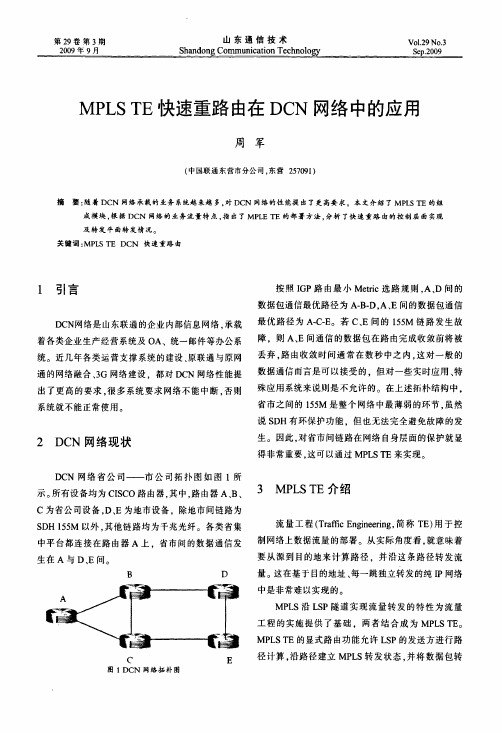
2D C N网络现状D C N网络省公司——市公司拓扑图如图l所示。
所有设备均为CI SCO路由器,其中,路由器A、B、C为省公司设备,D、E为地市设备,除地市间链路为SD H155M以外。
其他链路均为千兆光纤。
各类省集中平台都连接在路由器A上。
省市间的数据通信发生在A与D、E间。
B DC E图1D C N网络拓朴图按照I G P路由最小M et r i c选路规则。
A、D间的数据包通信最优路径为A.B.D,A、E间的数据包通信最优路径为A.C—E。
若C、E间的155M链路发生故障,则A、E间通信的数据包在路由完成收敛前将被丢弃.路由收敛时间通常在数秒中之内。
这对一般的数据通信而言是可以接受的.但对一些实时应用、特殊应用系统来说则是不允许的。
在上述拓朴结构中。
省市之间的155M是整个网络中最薄弱的环节。
虽然说SD H有环保护功能,但也无法完全避免故障的发生。
因此,对省市间链路在网络自身层面的保护就显得非常重要.这可以通过M PL ST E来实现。
- 1、下载文档前请自行甄别文档内容的完整性,平台不提供额外的编辑、内容补充、找答案等附加服务。
- 2、"仅部分预览"的文档,不可在线预览部分如存在完整性等问题,可反馈申请退款(可完整预览的文档不适用该条件!)。
- 3、如文档侵犯您的权益,请联系客服反馈,我们会尽快为您处理(人工客服工作时间:9:00-18:30)。
拓扑结构:原理说明:流量工程中tunnel的创立过程分为四步,分别为:1.开启全局和interface上面的mpls traffic engine tunnel,这一步为一个开关的作用。
2.配置端口的rsvp bandw idth,分别为各个interface指定一定的预留带宽用于分给上面的tunnel。
3.开启ospf-te或者其他协议的扩展功能,保障所有端口的流量情况被同步到area中的所有路由器,这在LER建立tunnel时提供了保障。
4.创建mpls traffic-engine tunnel,配置其带宽,优先级,recor route等属性。
通过RSVP-TE的path报文到达destination,并反向传送resv报文,用于分配标签和预留带宽。
从而真正创建出一条有保障能力的tunnel。
实验步骤:在所有设备之间运行OSPF和MPLS,保障所有设备都能够分到标签,基于标签转发。
此时,在PE1-P1-PE2上预留带宽为10M,在PE1-P2-PE2上预留带宽为20M。
在PE1上面建立dynamic tunnel和explicit r oute tunnel,看在大于或者小于等于链路所剩余带宽的情况下,是否能够成功创建mpls traffic-engine tunnel。
//CE1//ip cefmpls label protocol ldpinterface Loopback0ip address 1.1.1.1 255.255.255.255interface GigabitEthernet1/0ip address 10.0.0.1 255.255.255.0tag-switching iprouter ospf 1router-id 1.1.1.1network 1.1.1.1 0.0.0.0 area 0network 10.0.0.0 0.0.0.255 area 0//PE1//ip cefmpls label protocol ldpmpls traffic-eng tunnelsinterface Loopback0ip address 2.2.2.2 255.255.255.255interface Tunnel1ip unnumbered Loopback0tunnel destination 5.5.5.5tunnel mode mpls traffic-engtunnel mpls traffic-eng autoroute announcetunnel mpls traffic-eng priority 7 7tunnel mpls traffic-eng bandwidth 5000tunnel mpls traffic-eng path-option 5 dynamic tunnel mpls traffic-eng record-routeinterface GigabitEthernet1/0ip address 10.0.0.2 255.255.255.0tag-switching ipinterface GigabitEthernet2/0ip address 11.0.0.1 255.255.255.0mpls traffic-eng tunnelstag-switching ipip rsvp bandwidth 10000interface GigabitEthernet3/0ip address 13.0.0.1 255.255.255.0mpls traffic-eng tunnelstag-switching ipip rsvp bandwidth 20000router ospf 1mpls traffic-eng router-id Loopback0mpls traffic-eng area 0router-id 2.2.2.2network 2.2.2.2 0.0.0.0 area 0network 10.0.0.0 0.0.0.255 area 0network 11.0.0.0 0.0.0.255 area 0network 13.0.0.0 0.0.0.255 area 0ip explicit-path name 10m_link enablenext-address 11.0.0.2next-address 12.0.0.2//P1//ip cefmpls label protocol ldpmpls traffic-eng tunnelsinterface Loopback0ip address 3.3.3.3 255.255.255.255interface GigabitEthernet1/0ip address 11.0.0.2 255.255.255.0negotiation autompls traffic-eng tunnelstag-switching ipip rsvp bandwidth 10000interface GigabitEthernet2/0ip address 12.0.0.1 255.255.255.0negotiation autompls traffic-eng tunnelstag-switching ipip rsvp bandwidth 10000router ospf 1mpls traffic-eng router-id Loopback0 mpls traffic-eng area 0router-id 3.3.3.3log-adjacency-changesnetwork 3.3.3.3 0.0.0.0 area 0network 11.0.0.0 0.0.0.255 area 0network 12.0.0.0 0.0.0.255 area 0//P2//ip cefmpls label protocol ldpmpls traffic-eng tunnelsinterface Loopback0ip address 4.4.4.4 255.255.255.255 interface GigabitEthernet1/0ip address 13.0.0.2 255.255.255.0negotiation autompls traffic-eng tunnelstag-switching ipip rsvp bandwidth 20000interface GigabitEthernet2/0ip address 14.0.0.1 255.255.255.0negotiation autompls traffic-eng tunnelstag-switching ipip rsvp bandwidth 20000router ospf 1mpls traffic-eng router-id Loopback0 mpls traffic-eng area 0router-id 4.4.4.4network 4.4.4.4 0.0.0.0 area 0network 13.0.0.0 0.0.0.255 area 0network 14.0.0.0 0.0.0.255 area 0//PE2//ip cefmpls label protocol ldpmpls traffic-eng tunnelsinterface Loopback0ip address 5.5.5.5 255.255.255.255interface GigabitEthernet1/0ip address 15.0.0.1 255.255.255.0negotiation autotag-switching ip!interface GigabitEthernet2/0ip address 12.0.0.2 255.255.255.0negotiation autompls traffic-eng tunnelstag-switching ipip rsvp bandwidth 10000interface GigabitEthernet3/0ip address 14.0.0.2 255.255.255.0negotiation autompls traffic-eng tunnelstag-switching ipip rsvp bandwidth 20000router ospf 1mpls traffic-eng router-id Loopback0mpls traffic-eng area 0router-id 5.5.5.5network 5.5.5.5 0.0.0.0 area 0network 12.0.0.0 0.0.0.255 area 0network 14.0.0.0 0.0.0.255 area 0network 15.0.0.0 0.0.0.255 area 0network 16.0.0.0 0.0.0.255 area 0//CE2//ip cefmpls label protocol ldpinterface Loopback0ip address 6.6.6.6 255.255.255.255interface GigabitEthernet1/0ip address 15.0.0.2 255.255.255.0negotiation autotag-switching iprouter ospf 1network 6.6.6.6 0.0.0.0 area 0network 15.0.0.0 0.0.0.255 area 0Cisco MPLS流量工程TE隧道的基本配置(转)前言:mpls网络正在成为运营商主流网络趋势,目前国内运营商大上3G,同时也在部署更高效的mpls网络,电信的CN2(中盈承建),移动的CMnet(亚信承建),联通的集团IP承载网(中盈承建),CCIE的路由交换考试也加入了mpls可见一般,转载一篇mpls高级应用,供大家参考1 流量工程简介TE:Traffic Engineering的缩写,即流量工程的意思。
流量工程的本质就是将业务流量映射到实际的物理路径上。
就MPLS而言,其中心思想就是根据网络的实际情况为数据流确定合适的lsp并在该lsp上快速转发数据流,通过优化网络资源的使用,避免负载不均衡而导致的网络拥塞。
说到MPLS TE,不得不提到流量工程的四个基础功能部件,即信息发布、通路选择、信令和数据转发,这四个部件形成了整个流量工程的工作流程,因此是重中之重的内容,这里将介绍每个部件的主要作用。