ABB电磁流量计样本
ABB质量流量计样本

Zone 0, 1, 2, 21, 22
Zone 0, 1, 2, 21, 22
Class I Div. 1, Class I Div. 2, Zone 0, 1, 2, 20, 21
Class I Div. 1, Class I Div. 2, Zone 0, 1, 2, 20, 21
另询
一体型,分体型
选项 TE1" 加长变送器 " 的安装
图 9:T 介质 -50 º … 120 ºC(-58 … 248 º… 200(-58 … 392 ºF)1 带保温的安装 1 保温层
如果选择 TE1" 加长变送器 " 安装选项,流量计传感器保温如 图 11 所示。
图 10:T 介质 -50 º … 200(-58 … 392 ºF)的安装
液体测量精度 - 质量流量 - 体积流量 - 密度
- 温度 气体测量精度 接液材质 防护等级依照 EN 60529 待测介质允许的温度 认证与证书 1) - 防爆 ATEX/IECEx - 防爆 cFMus - 防爆其他认证 外壳
1)部分在准备中
标准型 FCB330
高精度型 FCB350
DN 10 ...200,PN 40 ... 100 DN 1/4" ...8" PN CL150 ...CL600 DN 10 ... 100 (1/4" ... 4") DIN 32676 (ISO 2852) BPE 三爪卡箍 DN 10 ... 100(1/4" ... 4")
图 1:垂直安装,可自排空
图 2:垂直安装,排放管(流向自上向下) 1 上游罐 | 2 流量计 | 3 孔板或缩径装置 | 4 阀门 | 5 下游罐
电磁流量计选型样本

:DN300-DN1200:≤0.6MPa 高压可定制
6)流量测量范围:
联系电话:010-87832746 010-61794317
网址
3
北京中航科仪测控技术有限公司
四 氟 乙 烯 和 F4 或 ETFE 乙烯
聚乙烯
PO
聚苯硫醚
PPS
化学性能略 逊于 F4
化 学 性 能 稳 60<℃ 定
150<℃
腐蚀性的酸 碱盐液体
腐蚀性的酸 碱盐液体 污水 热水
联系电话:010-87832746 010-61794317
网址
6
北京中航科仪测控技术有限公司
Qmax(m3/h) 271.0 424.0 662.0 954.0
内径(mm) 400
450
500
外接电源≤35V 导通时集电极最大电流为 250mA 10)供电电源:85-265V,45-63HZ 11)直管段长度:管道式:上游≥5DN,下游≥2DN 12)连接方式:流量计与配管之间均采用法兰连接,法兰连接尺寸应符合 GB11988 的规定. 13)防爆标志:MDIIBT4 14)环境温度湿度:-25℃-+60℃;5%-95%. 15)消耗总功率:小于 20W
流量测量范围对应流速范围是 0.1-15m/s
7)电导率范围: 被测流体电导率≥5us/cm(一体式),大多数以水为成分的介质,其电导率在 200-800 us/cm 范围内,均可选用电
磁流量计来测量其流量计. 8)电流输出: 负载电阻:0-10mA 时,0-1.5k¦¸ ,
4-20mA 时,0-750k¦¸ , 9)数字频率输出:输出频率上限可在 1-5000HZ 内设定带光电隔离的晶体管集电极开路双向输出.
ABB-电磁流量计

DN 3-300:Ex d e ia ma IIC T6… T2
CL I ZN2 Ex nA nC IIC T4 … T3
>DN 300:Ex d e ia IIC T6… T2
DIP:CL II,III / DIV1 / GP EFG / T70 OC … Tmedium DIP:CL II / DIV 1 / GP EFG
DN 3-300:Ex d e ia ma IIC T6… T2 >DN 300:Ex d e ia IIC T6… T2 DIP:CL II / DIV 1 / GP EFG
ൟো
FEP311ǃFEP315
⌟䞣ؐ䇃Ꮒ
ᷛ⌟˖ޚ䞣ؐⱘ 0.4 % 䗝乍˖⌟䞣ؐⱘ 0.2%
ᷛ鹵ሎᇌ㣗ೈ
DN 3 ... 2000 (1/10 “ ... 80 ")
FEPF3E2⟚P1(3ࡳ2无1㛑˄防˅᮴爆䰆功能)
ൟোὖ分䗄体˄型ߚԧൟ˅ 流⌕量䞣计䅵传Ӵ感ᛳ఼器
FFEEPP332255(˄防䰆爆⟚区ऎZo=nReQ2H/DiZH
FFEEPP33252(5˄防䰆爆⟚区ऎZon=eRQ1H/Div'.1L)Y˅
IEC
IEC
Ex nA IIC T6 … T3
DN 3-300:Ex e ia ma IIC T6… T2 Gb
>DN 300:Ex e ia IIC T6… T2 Gb
Ex tD A21 IP6X T85 OC … Tmedium
Ex tD A21 IP6X T85 OC … Tmedium
FM
ൟোὖ䗄˄䆒䅵䞛⫼䖰FবM䗕఼˅
⬉⌕䕧ߎ
4 ... 20 mAˈ᳝⑤᮴⑤
㛝ކ䕧ߎ
ৃՓ⫼䕃ӊᴀഄ䜡㕂Ў᳝⑤᮴⑤
电磁流量计样本

电磁流量计样本
一、概述 ........................................................................................................................................................................... 2 二、主要特点 ................................................................................................................................................................... 2 三、技术参数 ................................................................................................................................................................... 2 四、供货内容及订货须知 ............................................................................................................................................... 3
ABB AquaProbe 电磁流量计配置手册说明书

AquaProbeInsertion Type Electromagnetic Flowmeters Configuration Manual AquaProbe andAquaProbe TransmitterABB AutomationABB INSTRUMENTATIONAlthough Warning hazards are related to personal injury, and Caution hazards are associated with equipment or property damage,it must be understood that operation of damaged equipment could, under certain operational conditions, result in degraded process system performance leading to personal injury or death. Therefore, comply fully with all Warning and Caution rmation in this manual is intended only to assist our customers in the efficient operation of our equipment. Use of this manual for any other purpose is specifically prohibited and its contents are not to be reproduced in full or part without prior approval of Technical Communications Department, ABB Instrumentation.The CompanyABB Instrumentation is an established world force in the design and manufacture of instrumentation for industrial process control, flow measurement, gas and liquid analysis and environmental applications.As a part of ABB, a world leader in process automation technology, we offer customers application expertise, service and support worldwide.We are committed to teamwork, high quality manufacturing, advanced technology and unrivalled service and support.The quality, accuracy and performance of the Company’s products result from over 100 years experience, combined with a continuous program of innovative design and development to incorporate the latest technology.The NAMAS Calibration Laboratory No. 0255 is just one of the ten flow calibration plants operated by the Company, and is indicative of ABB Instrumentation’s dedication to quality and accuracy.BS EN ISO 9001St Neots, U.K. – Cert. No. Q5907Stonehouse, U.K. – Cert. No. FM 21106Stonehouse, U.K. – Cert. No. 0255EN 29001 (ISO 9001)Lenno, Italy – Cert. No. 9/90A Use of InstructionsHealth and SafetyTo ensure that our products are safe and without risk to health, the following points must be noted:1.The relevant sections of these instructions must be read carefully before proceeding.2.Warning labels on containers and packages must be observed.3.Installation, operation, maintenance and servicing must only be carried out by suitably trained personnel and in accordance with the information given.4.Normal safety precautions must be taken to avoid the possibility of an accident occurring when operating in conditions of high pressure and/or temperature.5.Chemicals must be stored away from heat, protected from temperature extremes and powders kept dry. Normal safe handling procedures must be used.6.When disposing of chemicals ensure that no two chemicals are mixed.Safety advice concerning the use of the equipment described in this manual or any relevant hazard data sheets (where applicable) may be obtained from the Company address on the back cover, together with servicing and spares information.CONTENTS Page1OPERATION1.1Intermittent Mode (2)1.2Continuous Mode (2)1.2.1Display (Continuous Mode Only) (2)1.3Totaliser (2)1.3.1Totaliser Reset (2)2PROGRAMMING2.1Programming the AquaProbe Transmitter (3)2.1.1Accessing and Using theMain Menu (3)2.2Vary Parameter Command (4)2.2.1Parameter Values (4)2.2.2Negative Parameter Values (4)2.2.3Changing Parameter Values (4)2.2.4Parameters (6)APPENDICESA1Psion Organiser Series 2 (7)A1.1Keyboard Designations (7)A2Psion Organiser Series 3 (7)A2.1Keyboard Designations (7)A3Husky Hunter Portable Computer (8)A3.1Keyboard Designations (8)A4Microscribe Series 300 (8)121.3TotaliserThe AquaProbe Transmitter is fitted with an 8 digit totaliser module. The totaliser is configured to count pulses in the forward direction only at a x1F rate, or at this rate divided by 10, 100 or 1000.Example – if x1F is in litres then the internal totaliser can be made to display cubic metres by selecting '÷ 1000' – see Fig.2.2 on page 5.1.3.1Totaliser ResetThe totaliser is reset by:a)Connecting Pin J of the output cable connector ('RESET' –white wire in cable MVBX 99147) to GND (Pins G, S or V).For full connection details see Section 4 in the AquaProbe Installation Manual.b)Applying the wand to the 'RESET' pad with Pins J and T ofthe output cable connector linked together (i.e. yellow and white wires of cable MVBX 99147) or by serial data lead assemblies MVBX 99117 or 99119.The totaliser is equipped with an overflow indicator. A small dot appears in the top left hand corner of the display when there is overflow from '99999999' to '00000000'.1OPERATIONThe AquaProbe Transmitter can be used in either a continuous or intermittent mode.1.1Intermittent ModeThe AquaProbe Transmitter measures the average flow rate over a period of approximately 5 seconds, at a regular user defined Intermittent Interval of 1 to 255 minutes. Between readings the transmitter is in a 'sleep' state resulting in minimal current usage. Battery life is proportional to the intermittent interval and can allow unattended operation from a small battery pack for in excess of one year. At the end of each measurement period the measurement is transmitted to any data terminal or data loggers connected to the AquaProbe Transmitter. The pulse output, reduced in frequency if required, is fed to an internal totaliser module.1.2Continuous ModeIf the wand is held over the 'ACTIVATE' pad for longer than 3seconds the AquaProbe Transmitter measures and displays flow continuously. Serial data is transmitted at approximately 1.2 second intervals and the frequency output is updated continuously. Once initiated continuous mode is maintained for a user defined Continuous Time of 2 to 255 minutes.Connection of 'A+' to ground or +12V (see AquaProbe Installation Manual) forces the AquaProbe Transmitter into continuous mode.1.2.1Display (Continuous Mode Only)The 4-digit liquid crystal display (l.c.d.) has automatic decimal point selection. The maximum number of figures displayed after the decimal point is automatically selected to give a resolution approximately equivalent to 0.001 m/s. Flow rate is indicated in chosen units (e.g. litres per second) to a maximum of ±9999 units.The display indicates the following overrange conditions:a)If the measuring range of the transmitter is exceeded(approximately 15 m/s), all displayed digits flash.b)If the flow rate exceeds the capacity of the display, a valueof ±9999 is shown continuously.32PROGRAMMING…Vary ParametersFlow Abort Save oror or or Testor 2.1.1Accessing and Using the Main MenuOn the data terminal, type a ‘V ’ and press enter and refer to Section 2.2 for full programming details.The Vary Parameter command allows changes to be made to the AquaProbe Transmitter internal data. To alter parameters 4 to 9 first enter the input security code for security level 1. To alter parameters 4 to 9 and 10 to 12 first enter the input security code for security level 2.On the data terminal, type an ‘F ’ and press enter. The AquaProbe returns to flow measurement, in continuous mode, using the parameter data entered in Vary Parameters until interrupted by a serial link.On the data terminal, type an ‘A ’ and press enter. The AquaProbe Transmitter returns to normal operation ignoring any alterations made to its parameters.On the data terminal, type an ‘S ’ and press enter. All data entered in Vary Parameters is saved and the AquaProbe Transmitter returns to normal operation. This is the only command which changes the AquaProbe Transmitter internal data.On the data terminal, type a ‘T ’ and press enter. The AquaProbe enters continuous mode until interrupted by a serial link. All flow settings and sensor calibration data are ignored and the display shows m/s only. This mode can be used in conjuction with the ABB Kent-Taylor VMD simulator to confirm correct operation.2.1Programming the AquaProbe TransmitterProgramming the AquaProbe transmitter allows various operating parameters to be changed. A security system consisting of two security codes is incorporated to restrict access to some parameters. If using a Psion Organiser, Husky Hunter Portable Computer or Microscribe Series 300 refer to APPENDICES for connection and/or keyboard operations.Table 2.1 Security Access to Parameters in the Vary Parameter MenuSecurity Level12Security Code to EnterSETUP TESTCALAccessible Parameters Parameters 1 to 8Factory set parameters 10, 11 and 12If required, remove page below above line to prevent unauthorised access to calibration details4…2PROGRAMMING2.2Vary Parameter Command 2.2.1Parameter ValuesParameter values are displayed as either floating point in the range ±1E –38 to ±1E+38, or integer in the range –128 to +255.Parameter values can be entered in either format but if an integer value is required then only the integer part of the entry is accepted.2.2.2Negative Parameter Valuesc)If a negative value is entered into parameter 7 (PU), thedisplayed flowrate is not affected but the forward/reverse pulse outputs are interchanged.2.2.3Changing Parameter Values – Fig. 2.1 and 2.2To change parameters 4 to 12 it is necessary to enter a security code – see Section 2.1.1 on previous page.Parameters 13 to 15 are not adjustable. Press 'Escape' to return to the main menu at any time.2PROGRAMMING…5c)Pulse Units – PU is the factor applied to the volume unitsto give the OUTPUT PULSE in the required units. It is the ratio between the volume flow rate units and the required pulse output units.Example 2– for a flow rate in m3 and a pulse output per m3the value of PU is 1.Example 3– for a flow rate in litres and a pulse output per m3 PU is 0.001.PU=Volume UnitsPulse Units1 litre1m31 litre1000 litres===0.001d)Time Mode – TM is the factor applied to the output pulseunits to give the INTERNAL TOTALISER in the required units. It is the ratio between the required totaliser units and the pulse output units and its value is expressed as a power of 10.Example 4– for a flow rate in m3 and a totaliser in m3 the value of TM should be 1. Since 1 is 100, TM = 0.Example 5– for a flow rate in litres and a pulse output in m3 the value of TM should be 1000. Since 1000 is 103, TM = 3.T M=Totaliser UnitsPulse Output Units1m31 litre1000 litres1 litre==Since 1000 = 103, TM = 32.2.4ParametersWhen programming the AquaProbe the following parametersare required:VU–Volume Units, e.g. litres, m3, gallons etc.TU–Time Units, e.g. per second, per minute etc.PU–Pulse Units (the value of pulse output),e.g. 1 pulse per m3.TM–Totaliser Mode (the value of internal totalisercount), e.g. 1 count per m3.a)Volume Units – VU is the parameter which defines theunits of measurement. It is calculated as the volume of a 1metre length of the pipeline in the required units. Table 2.2gives the values of VU for NOMINAL pipe sizes and isintended as a guide only. Calculate the actual value of VUfor a given pipe size using the formula:VU= x KWhere:D=internal diameter of pipeK=number of units in 1 m3,K=1000 if volume units are litresK=220.1 if units are Imperial GallonsK=264.17 if units are U.S. Gallonsn= a constant depending on the units of D,n=4,000,000 if D is in mmn=4 if D is in metresn=6200 if D is in inchesb)Time Units – TU is set to:1 for seconds60 for minutes3600 for hours86,400 for days.Example 1– for an 800mm pipeline and flow units of m3/hour,VU = 0.5026 and TU = 3600.…2PROGRAMMINGe z i Sep i Pl an imoN UVf oeu l aVmm)00,00,4=n(sehcn I)02,6=n(se r t i L)00,1=K()1=K(msno l l aG.pmI)1.022=K(sno l l aGSU)71.462=K(278.70514.134130.0799.6592.85248.99580.941940.0918.01569.21 0318.118386.07770.0065.514966.81 0457.51066.5217521.09376.72142.33 0596.918343.6913691.04152.346498.15 0626.320537.2827282.08932.266776.47 0805.13046.25625.06596.0115618.231 0173.930573.5874587.08719.2710374.72 02142.74049.031,1931.15959.842517.892 04121.550533.935,13935.15349.8334676.64 06199.26065.010,2610.24146.2449690.135 0247.8705.141,35141.31176.1965198.9283Table 2.2 Standard VU Parameter Values67A2Psion Organiser Series 3If using the Psion Organiser Series 3 the following must be carried out:a)Connect the Psion Organiser Communications LinkAdapter to the AquaProbe Transmitter using the Serial Interface Lead MVBX 99119.b)Refer to the Psion Series 3, 3 Link (RS232) handbook andinstall the Comms Application for use with the AquaProbe Transmitter. Access the 'Port' option on the 'Special' menu and set the following values.A1Psion Organiser Series 2If using a Psion Organiser Series 2 it is recommended that the mains adapter is used to power the organiser. The following must be carried out:a)Connect the Psion Organiser Communications LinkAdapter to the AquaProbe Transmitter using the Serial Interface Lead MVBX 99119.b)Access the Comms 'SETUP' mode and set the followingvalues.APPENDICESTransmission ParametersRate-4800Prtcl-none Pty-none CTS-n DTR-n Echo-n T/O-no Null-0 Press ENTER if acceptableReceiving ParametersRate-4800Prtcl-none Pty-none RTS-off DSR-n DCD-n T/O-no Serig-000 Press ENTER if acceptableMicroscribe 320 V 2.11 STATUSBaud Protocol TX Mode AutoLF Disp Audio4800Xon/off CHAR OFF40OFF Parity L.Echo EOF EOL Mode Sleep RESET OFF OFF CR NORM OFF BATTERY LEVEL100%XXXXXA3Husky Hunter Portable ComputerIf using a Husky Hunter Portable Computer the following must be carried out:a)Connect the Husky Hunter Portable Computer to theAquaProbe Transmitter using the Serial Data Lead MVBX 99117.b)Refer to the Husky Hunter Portable Computer handbookand enter the values shown below.A4Microscribe Series 300If using a Microscribe Series 300 the following must be carried out:a)Connect the Microscribe Series 300 to the AquaProbeTransmitter using the Serial Data Lead MVBX 99117.b)Refer to the Microscribe Series 300 handbook and enterthe values shown below.A3.1Keyboard Designations – Fig. A3.1…APPENDICES8PRODUCTS & CUSTOMER SUPPORTA Comprehensive Instrumentation RangeAnalytical Instrumentation•TransmittersOn-line pH, conductivity, and dissolved oxygen transmitters and associated sensing systems.•SensorspH, redox, selective ion, conductivity and dissolved oxygen.•Laboratory InstrumentationpH and dissolved oxygen meters and associated sensors.•Water AnalyzersFor water quality monitoring in environmental, power generation and general industrial applications including: pH, conductivity, ammonia, nitrate, phosphate, silica, sodium, chloride, fluoride, dissolved oxygen and hydrazine.•Gas AnalyzersZirconia, katharometers, hydrogen purity and purge-gas monitors, thermal conductivity.Controllers & Recorders•ControllersDigital display, electronic, pneumatic. Discrete single-loop and multi-loop controllers which can be linked to a common display station, process computer or personal computer.•RecordersCircular and strip-chart types (single and multi-point) for temperature, pressure, flow and many other process measurements.Electronic Transmitters•Smart & Analog TransmittersFor draft, differential, gauge and absolute pressure measurement. Also, liquid level and temperature.•I to P Converters and Field IndicatorsFlow Metering•Magnetic FlowmetersElectromagnetic, insertion type probes and watermeters.•Turbine Flowmeters•Wedge Flow Elements•Mass Flow MetersTransmitters, sensors, controllers and batch/display units.Level Control•Submersible, Capacitance & Conductivity.Pneumatic Instrumentation•Transmitters•Indicating Controllers•Recording Controllers Customer SupportABB Instrumentation provides a comprehensive after sales service via a Worldwide Service Organization. Contact one of the following offices for details on your nearest Service and Repair Centre.United KingdomABB Instrumentation LimitedTel: +44 (0)1480 475321Fax: +44 (0)1480 470787United States of AmericaABB Automation Inc.InstrumentationTel: +1 215-674-6000Fax: +1 215-674-7183ItalyABB Kent-Taylor SpATel: +39 (0) 344 58111Fax: +39 (0) 344 58278Client WarrantyPrior to installation, the equipment referred to in this manual must be stored in a clean, dry environment, in accordance with the Company's published specification. Periodic checks must be made on the equipment's condition.In the event of a failure under warranty, the following documentation must be provided as substantiation:1.A listing evidencing process operation and alarm logs at timeof failure.2.Copies of operating and maintenance records relating to thealleged faulty unit.The Company’s policy is one of contin u o u s prod u ct improvement and the right is reserved to modify the information contained herein without notice.© ABB 2000Printed in UK (10.00)ABB Instrumentation Ltd St. NeotsCambs.England, PE19 8EUTel: +44 (0) 1480 475321 Fax: +44 (0) 1480 217948ABB Instrumentation LtdAnalytical & Flow GroupStonehouse, Glos.England, GL10 3TATel: +44 (0) 1453 826661Fax: +44 (0) 1453 827856ABB Automation Inc.Instrumentation Division125 E. County Line RoadWarminster, PA 18974 USATel: +1 215-674-6000Fax: +1 215-674-7183IM/AP/AP–CMIssueAABB Instrumentation SpA22016 LennoComoItalyTel: +39 (0) 344 58111Fax: +39 (0) 344 58278。
ABB 电磁流量计
CL III/ DIV 1
DIP:
CL I, ZN 1 AEx d e [ia] CL II, III/ DIV 1/GP
IIC T6
EFG/ T70 OC
Zone21 AEx tD [iaD]
A21 IP6XT70 OC
cFM
cFM
XP:
NI:
CL I / DIV 1 / GP CL I,II/ DIV 2/ GP
FET325 (防爆区Zone2/Div.2)
FET321 (无防爆功能)
ϟϔ义
ATEX / NEPSI II 3 G Ex nA IIC T4 II 2 D Ex tD A21 IP6X T70 OC
IEC Ex nA C IIC Ex tD A21 IP6X T70 OC
FM NI: CL I,II / DIV2 / GP ABCDFG / T4 CL III / DIV1,2 / T4 CL I,II,III ZN 2 AEx nA IIC T4 DIP: CL II,III/ DIV1/ GP EFG/ T70 OC
˄DN 25 ... 1000)
ᇐ⬉⥛
> 5 S/cm˄20 S/cmˈᇍѢএ行ᄤ∈˅
⬉ᵕ
ϡ䫜䩶 1.4571 [316Ti]ǃ1.4539 [904L]ǃHastelloy BǃHastelloy Cǃ䪖䫅ড়䞥ǃ䪐钛ǃ䪑
䖛䖲ᴤ᭭
⺇䩶ˈϡ䫜䩶
䰆ᡸㄝ㑻
IP 65ǃIP 67ǃIP 68˄NEMA 4X˅
ѻકḋᴀ DѻSક/FEḋPP33ᴀ0000--CZNH-Rev.A
টདⱘ᪡⬠䴶 Ƶ টདⱘ᪡⬠䴶
- "Easy Set-up"ࡳ㛑ৃЎᙼᦤկᇐ㟾ᓣ᪡㦰ऩˈᐂ
ABB质量流量计样本
ABB质量流量计样本ABB是全球领先的工业技术公司,其质量流量计是一种用于测量液体或气体流量的仪器。
ABB质量流量计样本出色的设计和可靠性使其在工业自动化和流程控制领域得到广泛应用。
该样本将重点介绍ABB的质量流量计的特点和应用。
ABB的质量流量计采用了热式传感器技术,使用了革命性的质量测量原理。
其对流体中的物质进行连续热定点追踪,从而实现了高精度的质量流量测量。
同时,ABB质量流量计具有快速响应、宽测量范围和高可靠性等优点,非常适用于各种工业流程的质量流量控制。
ABB的质量流量计样本中包括多种型号和规格的流量计,以满足不同需求。
其中,一种常见的型号是ABB的CoriolisMaster。
这种质量流量计采用两根弯曲的管道,通过测量流体在管道中沿两个方向的振动来计算质量流量。
CoriolisMaster具有极高的精确度和稳定性,能够在各种工况下提供准确的测量结果。
另一种常见的ABB质量流量计是ThermalMaster。
这种流量计使用了Thermal Gas Mass Flow技术,通过测量热量传导来计算质量流量。
ThermalMaster适用于气体流量测量,能够测量极低至微米水平的流量,且不受压力、温度和湿度等环境因素的干扰。
除了CoriolisMaster和ThermalMaster之外,ABB还提供其他型号的质量流量计,如VortexMaster、MFM300和MassMaster等。
每个型号都具有特定的优点和适用范围,以满足不同行业、过程和应用领域的需求。
例如,VortexMaster是一种基于涡街原理的质量流量计,适用于液体和气体的测量。
它具有无移动部件、准确可靠和耐久性强等特点。
MFM300是一种用于纳米流量测量的质量流量计,适用于实验室和研究领域的应用。
它能够测量液体和气体的微小流量变化,提供高精度和稳定性。
MassMaster是一种用于大流量测量的质量流量计,适用于石油、化工和电力等行业的应用。
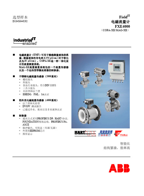
ABB电磁流量计FXE4000选型样本
■ 转换器 - 通讯方式采用PROFIBUS DP,HART-协议, FOUNDATION现场总线,PROFIBUS PA, ASCII - 脉冲输出,可组态(有源/无源) - 外置的EEPROM芯片 - 图形显示
> 5 µS/cm
> 5 µS/cm
(软化水为20 µS/cm)(软化水为20 µS/cm)(软化水为20 µS/cm)(软化水为20 µS/cm)(软化水为20 µS/cm)
电极
工艺接头材料
-
-
保护等级
IP67
IP67
IP67
IP67
IP67
流体温度 *
-25 ~ +130 °C
-25 ~ +130 °C
预热时间 30分钟
模拟输出影响 与脉冲输出相同,±0.1 %
标准校正(脉冲输出):
Q>0.07 Rangemax ±0.5 %
Q<
±
Rangemax = 流量计尺寸的最大流速(10 m/s时)
D184S044U02
操作原理
法拉第感应定律(指的是当导体通过磁场时会在导体内部产生 电势)即为电磁流量计测量的基础原理。
这种测量原理可应用于具有导电性的流体,该流体流入磁场垂 直于流体方向的管道,(参见示意图。)
在流体中感应生成的电势可利用对称布置的两个电极进行测 量。信号电压UE 与磁感应强度B,电极间距D以及流体平均速 度v成正比。
由于磁感应强度B与电极间距D为常量,所以信号电压UE与平 均流速v成正比。用于计算体积流速的等式表明信号电压UE与 体积流量成线性正比。
ABB 电磁流量计
安全要点介绍:使用调节电磁流量计系统(EMF)是按照设计技术制造操作安全的。
流量计根据规范专门安装使用。
每一个超过规范的使用被视为违规。
因此制造商不承担任何危险的结果。
使用者自责如此使用的危险结果。
使用的说明包括安装、起动和随后制造商特殊要求的服务。
安装、起动和操作人员在试图安装、启动和服务之前请阅读本使用说明和安全要点。
只有合格的人员才能接近该仪表。
该人员必须熟悉在说明公告内包含的警告和操作要求。
遵守在本文件中通过符号标明的警告要点:危险材料信息如果进行维修时。
了解1986/08/27的废料排放法(A bfG.11, 特殊废料)。
特殊废料的业主是有责任注意和根据1986/11/01的危险材料法(GefStoffV,17,通过保护责任)老板也有责任保护其员工。
我们必须提及:a)全部仪表本体和/或仪表转换器要返回ABB自动化公司进行维修是可完全避免任何危险的材料(酸、碱、溶剂等);b)仪表本体必须平直因此危险的材料不被压制。
在仪表室和管道之间有空穴在本体上。
因此在测量危险材料后这些空穴可能被压制(见危险材料法- GefStoffV)。
两半仪表室使用螺栓固定。
对于仪表本体大于14” DN350,排液孔位于室底部。
为了避免危险的材料进入磁性线圈和电极区可以去除排压。
c)为了工作和维修,要求记录完成a)和b)的测量表。
d)任何去除危险材料的成本将有使用者承担。
内容:页1. 仪表和转换器的协调1.1 适用性1.2 协调型号1.3 使用说明1.4 规格页1.5 仪表本体设计概论1.6 功能描述2. 装配和安装2.1 检查2.2 流量计本体安装要求2.2.1 流量计本体安装2.2.1.1 保护等级 IP68 的安装2.2.2 高温设计的安装2.2.3 大尺寸管线的安装3. 流量计可替代的部件3.1 更换部件表:模块盒 10DX3121/31223.2 更换部件表:铝连接盒≤12” DN3004. 使用说明的有关安全章节4.1 接地4.1.1 在管线上应用负极腐蚀保护(CCP)的安装和接地4.1.1.1 应用负极腐蚀保护电压管线内部绝缘4.1.1.2 混合系统: CCP和接地保护的管线4.1.2 供电的连接4.1.2.1 供电和信号线的连接4.1.2.2 信号线解释4.1.3 连接图4.1.4 连接区域5. 起动5.1 流量计本体的初步检查5.2 保养6. 使用转换器的流量计本体的测试和错误查找1. 仪表和转换器的协调!您是使用一直流脉冲流量计系统。
ABB电磁流量计样本

产品样本 DS/FET200-ZH Rev.A电池供电型电磁流量计水计量的智能解决方案■宽量程,高精度- 缩径设计可确保夜间小流量和白天峰值流量测量- 通径设计可以应用于常规测量■ OIML R49和MID认证- 通过OIML R49 Class 1和Class 2以及MID形式认证,并适用于各种管道安装方式■安装位置不受限制- 对前后直管段没有要求并通过OIML R49认证■良好的兼容性- 多种形式的适配器可以保证现有的变送器和原有的传感器连接■完全密封的变送器- 所有的输入输出通过外部的IP68接插头方式■可选内置的多速多通道多参数的数据记录器- 高精度高分辨率的数据记录器■变送器可用SMS短信方式直接发送数据- 方便实现对流量计管网的数据的自动处理功能■电池、电源或可再生能源供电方式- 可选10年使用寿命的电池AquaMaster 3 FET200电磁水表AquaMaster 3 FET200电磁水表新一代商用水表AquaMaster 3的标准口径为15-600 mm(1/2-24 in.),可提供水行业流量测量的整体解决方案。
出色的性能、创新的特点和优良的用户效益,以及较低的使用成本,使得AquaMaster 3能够成为区域计量、大用户计量收费、主干管和水处理应用领域中的首选。
AquaMaster 3还可以提供口径为25-300 mm (1-12 in.)的通径结构,适用于灌溉等应用,在这些应用中,零压损比量程和精度等要求更为重要。
AquaMaster 3专门为水行业设计,以满足水行业对日益提高的计量性能的严格要求,实现了更加高效、更加具有成本效益的使用,符合日益严格的法律法规要求。
AquaMaster 3基于ABB诸多成熟的技术并且得到ABB专业技术的支持,作为一个世界领先水平的流量计制造商,过去十几年ABB在水流量计量领域中拥有许多首创技术优势。
例如AquaMag™、MagMaster™、AquaProbe™以及CalMaster™等。
ABB电磁流量计

ABB电磁流量计一、工作原理:根据法拉第电磁感应定律,导体切割磁力线产生感应电势,公式:E=BLVL=D(管径),由电极测出,B由励磁提供。
型号基本有:分体型MAG-XE(类型防止管道震动)一体型COPA-XE二、安装:●必须保证衬里完整(保护电极)●安装位置为上游3D,下游2D●尽量垂直,以保证管道充满流体●外壳接地三、接线端子图:1、2信号线带屏敝V8、V9脉冲输出G2、P7触点输出G2、X1触点输入+、-电流输出3屏敝L、N220V ACSE接地端M1、M3励磁提供四、参数设定:按键说明:#C/ C E此键用于操作模式与菜单之间的切换。
▼STEP↑此键是两个箭头键之一,用于菜单的正向滚动。
▲DA TA↓此键是两个箭头键之一,用于菜单的反向滚动。
▼ENTER在同时按下STEP和DATA时,回车键的功能被激活。
▲参数菜单:Prog.protection 程序保护 On/ Off↓Prog .prot.code程序保护代码↓Language语言↓SubmenuPrimary子菜单ENTER仪表口径;仪表系数。
↓Range量程↓Low flow cutoff小流量切除↓Damping阻尼时间↓Filter滤波器ON/OFF↓┇┇Rate unit 流量单位↓Cuttent output电流输出↓Detector e.pipe 空管检测↓Totalizer 积算器↓Display 显示1st Line :瞬时流量%、工程单位、累积值、位号。
2nd Line:一般选择累积值。
↓Operating mode 工作模式↓Store data in 存储数据External EEPROM↓TAG number 仪表位号五、常见故障代码:0空管,管道没有充满流体1A/D转换器饱和2正或负参比信号太小3流量超过130%4外控回零被触发5RAM中数据出错6积算器量值出错7正参比信号过大8正参比信号太小9电源频率或驱动器、数字板出错A流量超过上限报警B流量超过下限报警C外EEPROM数据出错或模块未装。
ABB密度计质量流量计样本
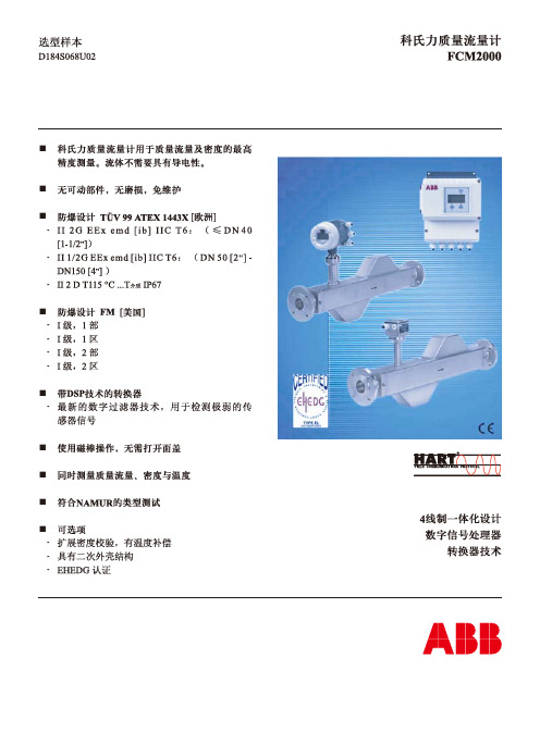
具有数字信号处理器(DSP)的质量转换器
FCM2000 的转换器包含一个数字信号处理器(DSP),可以 用它进行质量流量与密度值的最高精度测量。科氏力传感器信 号被立即转换为数字信息,而无须任何中间模拟步骤。
下图所示的推荐安装方式仅适用于可以安装具有较小截面的管 道大小头或孔板(以防止流量计传感器在测量过程中发生部分 排空)时。
原料储槽
图5:垂直安装,自排空(向上流动)
水平安装
图6:水平安装
水平安装,自排空
流量计传感器 孔板 管道缩径部分 阀门
产品储槽
图8:在下降管道中的安装
图7:水平安装,自排空,α 2-4° 6
5
科氏力质量流量计 FCM2000
D184S068U02
安装说明
垂直安装
最佳的安装方向为垂直安装,且流动方向朝上,如下图所示。 这样做的好处是,在流量为零时,流体所含的任何固体将会向 下沉降,而任何气泡将会向上移动,并从测量管排出。此外, 这还便于排空测量管。由此可以避免发生沉积。
下降管道中的安装
安装简便、流量范围广、过程连接选择多样、以及资金回收 快,这些优点使FCM2000成为生产过程应用的最佳选择。
有介质流动时,管子向 内移动时科氏力的方向
有介质流动时,管子向 外移动时科氏力的方向
图3:FCM2000 双管型流量计传感器
Fc = -2m ( ω ⋅ v) Fc = 科氏力 图1:科氏力简化示意图
ABB 差压流量计 综合样本
大 约 重 量 ,k g
法兰额定压力
150 300 600
10
11
10
12
13
14
20
22
23
23
25
27
31
36
38
Chemical Tee密 封 连接口
流向
口径4"-24"
测量 管口
径
4
6
8
10
管道的
12
14 所示为RFSO法兰 16
18
20
24
A尺寸 B尺寸 C尺寸 D尺寸
30.00 15.00 7.50 0.81 34.00 18.00 9.00 0.81 36.00 20.50 10.25 0.81 38.00 23.50 11.75 0.81 44.00 26.50 13.25 0.81 46.00 28.00 14.00 0.81 49.00 30.50 15.25 0.81 52.00 33.50 16.75 0.81 56.00 37.00 18.50 0.81 62.00 42.00 21.00 0.81
差压流量仪表
综合样本
ABB 仪器仪表 压力、流量、分析仪表、温度、执行机构、液位......
A B B
差压流量仪表综合样本
公司简介
在仪器仪表领域,ABB已有150多年的传承。许多世界领先的公 司(其中最为著名的有HarTMann&Braun、Elsag Bailey、Kent/ Taylor Instruments、Fisher&Porter、Sensycon及Tieghi) 现 在 都是ABB仪器仪表的一部分。在这150年中,我们发明并完善了 无数的产品。 在 各 种 应 用 领 域 和 各 行 各 业 中 ,ABB正 与 我 们 的 客 户 通 力 合 作: ABB仪 器 仪 表 不 仅 能 提 供 高 质 量 的 设 备 解 决 方 案 , 而 且 实 现 高 度的客户关怀,不断为其促进事业的发展。 ABB仪 器 仪 表 能 够 在 全 世 界 范 围 , 为 工 业 过 程 的 整 个 阶 段 提 供 智能支持。 近100多 年 来 ,ABB在 差 压 仪 表 领 域 广 泛 汲 取Kent、Taylor 及 Bush Beach宝贵的技术和应用经验,不断的研发与创新,形成 自己的技术特色,产品包括处于行业领先地位的楔型流量计、 一体化孔板流量计、均速管流量计等一系列产品,我们还可提 供各类差压测量设备——包括一次元件、变送器、控制设备 等。 ABB差 压 仪 表 一 直 关 注 和 支 持 中 国 工 业 的 发 展 , 尤 其 在 过 程 行 业与化工、石油、天然气行业,ABB差压仪表得到广泛应用。 ABB的 高 质 量 产 品 能 够 得 到 全 球ABB工 厂 训 练 有 素 的 工 程 师 团 队的有力支持——从安装、调试到维护以及培训。 在中国,我们在北京、上海、广州、西安成立了仪器仪表部的 技术服务中心,有专业的技术工程师为您提供咨询及现场服 务,您可拨打400-620-9919随时垂询。
电磁流量计样本范文

电磁流量计样本范文样本名称:电磁流量计(Magnetic Flowmeter)1.产品特点:-非接触式测量:传感器与液体之间无接触,不会对流体产生压力损失和阻力。
-适用范围广:可用于测量各种导电液体,包括水、酸、碱、溶液等。
-准确度高:传感器采用先进的数字信号处理技术,测量精度高,稳定性好。
-宽工作温度范围:适用于-40°C至+80°C的工作环境。
-耐腐蚀性强:传感器材质选用耐腐蚀材料,可在腐蚀环境下长期稳定工作。
-维护简便:无可动部件,不易产生故障,维护成本低。
2.技术参数:-测量范围:0-1000m3/h-工作压力:常压至2.5MPa-电源:220VAC或24VDC-输出信号:4-20mA、RS485-耐压性能:150%满量程-精度等级:0.2级、0.5级、1级-介质温度:-40°C至+80°C3.结构和工作原理:-传感器:传感器通常采用分离型结构,由上流和下流两部分组成。
上部包含了电磁线圈和流量计管道,下部包含了电磁感应电极,通过液体中的电导引起的感应电动势测量液体的流量。
-转换器:将传感器采集到的电动势信号转换为标准信号输出,通常有4-20mA和RS485两种输出方式。
转换器还可以对流量进行放大、线性化等处理,并可以通过键盘和显示屏对各种参数进行设置和显示。
4.安装和使用:-安装:安装电磁流量计时应注意流量计的正常工作需要充分均匀的流动,因此在安装流量计时应避免弯头、泵进口、出口等处的干扰,安装时应将流量计放置于充满液体的管道中。
-使用:使用前需要进行校准和参数设置,根据需要设置输出信号范围和单位等参数,确保测量结果准确可靠。
同时,应定期对流量计进行校验和维护,以确保其正常工作。
5.应用领域:以上是一份关于电磁流量计样本的详细介绍,介绍了它的特点、技术参数、结构和工作原理、安装和使用方法,以及应用领域等信息。
电磁流量计作为一种广泛应用的流量测量仪器,在工业生产和公共设施中发挥着重要作用。
ABB质量流量计样本
ABB质量流量计样本ABB是一家全球领先的工业自动化和电力技术公司,提供广泛的产品和解决方案,涵盖工业流程控制、电力传输与分配以及建筑自动化等领域。
在工业领域中,ABB的质量流量计是一种重要的仪器设备,用于测量流体的质量和流量。
以下是ABB质量流量计样本的详细信息。
1.测量精度高:ABB质量流量计采用先进的热传导技术,能够实现高精度的质量流量测量,满足工业生产过程对于流量测量精度的要求。
2.宽测量范围:ABB质量流量计适用于各种工业应用场景,具有宽广的测量范围,能够满足不同流量条件下的测量需求。
3.耐压能力强:ABB质量流量计的流体传感器具有高强度的耐压能力,能够承受高压工况下的稳定工作,保证测量结果的准确性和可靠性。
4.抗干扰能力强:ABB质量流量计具有良好的抗扰动能力,能够抵抗来自流体介质中的振动和噪声以及管道内的颗粒物等干扰信号,确保测量结果稳定可靠。
5.操作简便:ABB质量流量计采用先进的数码显示和操作界面,操作简便,人机交互友好,用户可根据需要进行参数设置和查询。
6.通信接口丰富:ABB质量流量计支持多种通信接口,如MODBUS、HART等,便于与其他设备的联网通信和数据交互。
7.可靠性高:ABB作为一家全球知名的工控产品供应商,质量流量计的可靠性得到了广泛的认可,其产品经过严格的质量控制和测试,保证了其长期稳定可靠的使用。
以上是ABB质量流量计样本的主要特点和优势。
ABB质量流量计广泛应用于石油化工、电力、水处理、生物工程等工业领域,并取得了良好的效果。
无论是在工业流程控制还是生产过程管理中,ABB质量流量计都扮演着重要的角色,并为用户提供准确可靠的质量流量测量数据。
电磁流量计选型样本
电磁流量计选型样本电磁流量计是一种通过测量电磁感应原理来测量管道中液体或气体流量的仪表。
它广泛应用于水处理、化工、石油、冶金、食品等行业中。
在选型电磁流量计时,需要考虑一系列参数和因素。
下面将介绍一般选型过程,并根据实际应用场景,提供一个电磁流量计选型样本。
首先,选型时需要考虑的参数包括测量介质的性质、流量要求、工艺参数、环境条件和要求的准确度等。
1.测量介质的性质:包括液体或气体的种类、流体状态(单相或多相)、温度、压力、粘度等。
不同介质的性质差异会对电磁流量计的选型产生影响。
2.流量要求:包括流量范围、最大流速、最小流速、流量变化范围和流速的变化频率。
根据实际需求,选择适合的电磁流量计。
3.工艺参数:包括管道尺寸、管道材质、连接方式等。
电磁流量计的选型需要符合管道的尺寸和材质要求,并能与管道方便地连接。
4.环境条件:包括温度、湿度、工作压力、防爆等级和防护等级等。
根据实际环境条件,选择具备相应防护等级和防爆等级的电磁流量计。
5.准确度要求:根据实际应用,选择准确度要求符合的电磁流量计。
一般常见的准确度等级有0.5级、1级、1.5级、2级等。
应用场景:化工生产中的液体流量测量1.测量介质的性质:-液体类型:硫酸-温度:40℃-压力:1.5MPa-粘度:0.1~0.5mPa·s2.流量要求:-流量范围:10~100m³/h-最大流速:20m/s-最小流速:0.1m/s-流量变化范围:可大于50:1-流速变化频率:1次/分钟3.工艺参数:- 管道尺寸:DN100(内径100mm)-管道材质:碳钢-连接方式:法兰连接4.环境条件:-温度:常温-湿度:相对湿度不超过85%-工作压力:1.6MPa-防护等级:IP65- 防爆等级:ExdIIBT45.准确度要求:1级根据上述要求,可选择以下型号的电磁流量计:XX型号电磁流量计。
XX型号电磁流量计的主要特点和性能如下:-采用先进的电磁感应原理,测量准确度高,反应迅速。
ABB电磁流量计FXE4000选型样本
ABB电磁流量计FXE4000选型样本FXE4000流量计的选型样本是指供用户参考的关于该型号流量计的详细信息,以帮助用户选择合适的型号和规格。
下面是一个关于ABB电磁流量计FXE4000选型样本的1200字以上的介绍:ABB电磁流量计FXE4000是一款领先的电磁式流量计,专用于测量和监控各种液体的流量。
它采用先进的电磁测量原理,通过感应液体中的电磁信号,来测量液体的流量。
FXE4000电磁流量计具有高精度、稳定性好、抗干扰能力强等优点,广泛应用于化工、制药、食品、电力等各个工业领域。
FXE4000电磁流量计的选型样本包含了以下几个方面的详细信息,帮助用户选择合适的型号和规格:1.流量计型号和规格:FXE4000电磁流量计有多种型号和规格可供选择,用户可以根据自己的具体需求来选购。
选型样本中包含了各个型号的详细参数,包括流量范围、测量精度、工作压力、工作温度等。
2.环境适应能力:FXE4000电磁流量计具有很强的环境适应能力,可以在各种恶劣的工业环境下工作。
选型样本中包含了一些典型的工业环境的介绍,用户可以根据自己的工作环境选择合适的型号。
3.安装方式和要求:FXE4000电磁流量计可以采用多种安装方式,例如垂直安装、水平安装等。
选型样本中包含了各个安装方式的详细步骤和要求,用户可以根据自己的安装条件选择合适的方式。
4.接口类型和协议:FXE4000电磁流量计支持多种接口类型和通信协议,可以与其他设备进行联网通信。
选型样本中包含了各种接口类型和协议的介绍,用户可以根据自己的通信需求选择合适的型号。
5.配件和附件:FXE4000电磁流量计的选型样本中还包含了一些附件和配件的介绍,例如电源适配器、串口线、安装支架等。
用户可以根据自己的需求选择相应的配件和附件。
总之,ABB电磁流量计FXE4000的选型样本提供了详细的商品信息和技术参数,帮助用户选择合适的型号和规格。
用户可以根据自己的实际需求来筛选合适的型号,并且可以参考样本中的附件和配件提供的信息,来完善设备的配置。
ABB电磁流量计FXE4000选型样本

ABB电磁流量计FXE4000选型样本
首先,我们需要确定测量范围。
ABB电磁流量计FXE4000提供了不同
的尺寸和测量范围选项,以适应不同的应用需求。
对于小流量应用,可以
选择较小的尺寸,而对于大流量应用,则需要选择相应的大尺寸。
其次,我们需要考虑材质和连接方式。
ABB电磁流量计FXE4000提供
了多种材质选项,如碳钢、不锈钢和钛等。
不同的材质适用于不同的介质,例如碳钢适用于一般工业用途,而不锈钢则适用于化学腐蚀介质。
此外,
还需要选择合适的连接方式,例如法兰连接或螺纹连接等。
第三,我们需要确定输出信号。
ABB电磁流量计FXE4000提供了多种
输出信号选项,例如模拟输出信号(例如4-20mA或0-10V),数字通信(例如Modbus RTU或Profibus DP)和开关量输出等。
根据系统的要求,选择适用的输出信号选项。
接下来,我们需要考虑防护等级。
ABB电磁流量计FXE4000具有不同
的防护等级选项,例如IP65或IP67等。
根据现场环境的要求,选择合适
的防护等级,以确保设备的安全和可靠性。
最后,我们需要确定安装方式。
ABB电磁流量计FXE4000提供了多种
安装方式,如法兰安装、挂装和螺纹安装等。
根据具体的安装需求,选择
适合的安装方式。
总结起来,选型样本需要考虑测量范围、材质和连接方式、输出信号、防护等级和安装方式等因素。
选择合适的ABB电磁流量计FXE4000能够确
保流量的准确测量和系统的可靠运行。
电磁流量计ABB_MFE
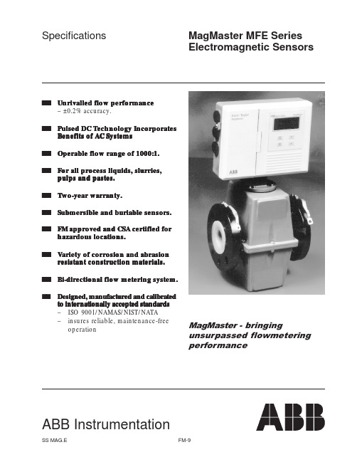
SS MAG.EFM-9SpecificationsABB InstrumentationMagMaster MFE SeriesElectromagnetic Sensorss s Unrivalled flow performance– ±0.2% accuracy.s s Pulsed DC Technology IncorporatesBenefits of AC Systems s s Operable flow range of 1000:1.s s For all process liquids, slurries,pulps and pastes.s s Two-year warranty.s s Submersible and buriable sensors.s s FM approved and CSA certified forhazardous locations.s s Variety of corrosion and abrasionresistant construction materials.s s Bi-directional flow metering system.s s Designed, manufactur Designed, manufactured and calibrateded and calibrated to inter to internationally accepted standar nationally accepted standar nationally accepted standards ds –ISO 9001/NAMAS/NIST/NATA –insures reliable, maintenance-freeoperationMagMaster - bringingunsurpassed flowmetering performanceSPECIFICATIONSConfiguration:Transmitter may be integral with sensor for sizes 1/2 to 16-inches (400mm) or remote from sensor for all sizes. Separation (remote transmitters):The maximum cable length in feet is the lower of 330 feet (100m) or 15 x the conductivity (µS/cm). Longer lengths are special order.Accuracy (under forward flow reference conditions) with MagMaster transmitterFlanged sensors:Display, Serial comms, Frequency output:±0.2% of reading or ±0.003 ft/sec (0.001m/s) (whichever is greater) up to a maximum velocity of >49 ft/sec(15m/s). See Figure below.Analog output:As Frequency output plus ±0.008mA.Wafer sensors:As for flanged meters plus ±0.3% of reading.Pressure effect:Less than 0.15% over the operating range of theinstrument.Temperature effect:Sensor:<±0.03% of rate per 10°C. Repeatability & Reproducibility:±0.05% or ±.0008ft/s (±0.25mm/s), whichever is greater. Conductivity:Liquids and slurries having a conductivity of not less than 5µS/cm (5µmho/cm).Mounting:Directly into pipeline at any attitude. Electrodes can not be in vertical plane. Flow must be up if installed in a vertical pipe. Recommended Mating Pipe Conditions:Upstream: 5 to 10 diameters straight pipe dependingon performance requirements andupstream disturbance.Downstream: 2 to 3 diameters straight pipe dependingon performance requirements anddownstream disturbances.Power consumption:Less than 20VA with transmitter.Hazardous Area Certification:FM approved and CSA certified for Class I, Div. 2, Groups A, B, C, D hazardous locations, 0.5-24 inches (15-600 mm). NOTE:FM approved sensors for hazardous locations include an intrinsic safety shunt circuit for the electrodesallowing for a Div. 1 rating inside the pipe. The circuitis located in the larger than standard terminal boxhousing. CSA certified sensors for hazardouslocations may or may not include the circuit,depending on the rating inside the pipe. Calibration:3 point, 8 point, witnessed, NAMAS (8- to 24-inch only), slurry calibration options.Sensor cable connection:0.5 inch NPT--single opening. A single cable is available that provides for the coil drive and electrode signals. See Options.INTRODUCTIONMAGMASTER flowmeters provide new levels of flow measurement and performance with an exclusive sensor design featuring ultra-linear magnetics and a patented signal processing system. The MagMaster utilizes pulsed dc technology coupled with the benefits of ac design.Two modes– Process MAGMASTER and Slurry MAGMASTER are available in a wide range of sizes and options including electrode materials, liner materials andtransmitter capabilities.SS MAG.E FM-10SPECIFICATION – SENSORSMAGMASTER sensors are available in flanged and wafer styles and come in a wide choice of lining and electrode materials to satisfy all applications. (Refer to Table B for option details.)Sizes (Nominal Bore):1/2-inch to 24-inches (15mm to 600mm).Refer to MAG.PLUS specifications for larger sizes. Refer to Micro-MAG specifications for sizes smaller than 1/2-inch. Metering Tube:Lined stainless steel. (304 SST)Lining:PFA-Perfluoroalkoxy fluorocarbon – UKWFBS* (chemically resistant to almost all liquids),Elastomer - chlorobutylrubber and EPDM – UKWFBS*, Polypropylene – UKWFBS*,Ebonite (hard rubber), Bonded FEP (Viton seals), Polyurethane and Neoprene.Polyurethane meeting FDA approval also available for potable water (consult factory for ordering information)* United Kingdom Water Fittings Bylaws Scheme (UKWFBS) listed for potable water.Electrodes:Non-removable, 316 S.S, Hastelloy C, Titanium, Tantalum and Platinum/Iridium. Treated titanium for pulp and paper applications where concentrations of stock are greater than 5% or liquid contains long fibers regardless of the concentration. Tungsten carbide coated electrodes for high abrasion mining, cement or flyash applications. Grounding Electrode:Fitted as standard in flanged meters in the same material as measuring electrodes.Grounding Ring:For Wafer meters or liner protection.< 12 in (300 mm) = 316 SST, >12 = 304 SSTNote: Pressure LimitationsFlanged meters:Sizes 0.5-inch to 24-inch (15mm to 600mm):maximum pressure dictated by flange rating.Wafer meters: 725 psi (50 bars)Process Connections:Flanged meter-Carbon steel flanges to mate with BS4504, DIN, UNI, AFNOR, ANSI, AS2129 and BS10 flanges.Wafer meters mate with the flange standard BS4504 (6, 10, 16, 25 and 40 bar), BS10 Table D & E, and ANSI 150 for 1, 1.5, 2.0, 3.0, 4.0, 6.0 inch (25, 40, 50, 80, 100, 150 mm) or with ANSI 300 for 1, 1.5, 3.0, 4.0 inch (25, 40, 80, 100 mm). NOTE: No 2 inch or 6 inch ANSI 300 Wafer meters. Temperature:Sensors (with integral transmitters, except Wafer design): Ambient:–10 to +60°C (14 to 140°F)Process Fluid:Polyurethane lining:–10 to +70°C (14 to 158°F)All other linings:–10 to +80°C (14 to 176°F) Ambient and process fluid is limited to -10° to 60°C for the integral CSA-certified hazardous area meterWafer Meters: Maximum Temperature of 26.6°C (80°F) Sensors (remote transmitter): see Table A. Environmental Protection:Sensors with integral transmitters:NEMA 4X/IP65Flanged sensors, with remote transmitters*:NEMA 6P/IP68 with potted terminal box and cable- up to 33 ft (10 M) depth.Buriable:3 ft. (1m) to 16 ft. (5m) depth (to top of sensor).Wafer sensors: NEMA 4X/IP65*NOTE:All remote sensors are supplied with potting compound for sealing on-site or can be ordered with cable connected to sensor and terminal box potted.Sensor Housing:Wafer meters:Epoxy coated SG iron (nodular cast iron)Flanged meters:1/2 to 6-inch (150mm) Cast aluminum alloy, Epoxy coated.Non-approved/certified meters:8- to 12-inch (200 to 300mm) ABS plastic14- to 24-inch (350 to 600mm) GRP (Glass Reinforced Plastic)Approved/certfied & High temperature meters:8- to 24-inch (200 to 600mm) Fabricated steel.Liner Material vs Process Fluid Temperature Maximum (°C/°F)FEP/PFASensor Construction Poly-“Teflon” &Ebonite Poly-Neoprenepropylene Elastomer urethaneABB Standard, Non-hazardous, 1/2" to 6", metal cased 8" to 24"26.6/80120/24895/20370/158110/230 FM approved, CSA certified, Non-Hazardous, high temp., 1/2" to 24"26.6/80120/24895/20370/158110/230 FM approved, CSA certified, Hazardous, high temp., 1/2" to 24"26.6/80120/248*95/20370/158110/230* ABB Standard, Non-hazardous, > 24", plastic case 8" to 24"N/A80/17680/17670/15880/176 FM approved, CSA certified, Non-Hazardous, 1/2" to 24"26.6/8080/17680/17670/15880/176 FM approved, CSA certified, Hazardous, standard temp., 1/2" to 24"26.6/8060/14060/14060/14060/140 Table A Temperature Limits for Sensors (Remote Transmitter) at -30 to 140°F (-35 to 60°C) Ambient* Note: 8- to 24-inch (200 –600mm) sizes limited to 100°C (212°F)SS MAG.E FM-11SS MAG.EFM-12Polyurethane and FEP are part face liningsDIMENSIONS1/2- to 6-inch (15 to 150mm) flanged sensors without transmitter or terminal boxPolyurethane and PFA are part face liningsDIMENSIONSWafer meters without transmitter or terminal boxDIMENSIONSDIMENSIONSStandard terminal box (mounted on sensor)Hazardous area terminal box (mounted on sensor)SS MAG.E FM-13Table B Flowmeter SizingNote 1:Flow rate deviation listed is the plus and minus inaccuracy in terms of USGPM for all flows below the Minimum Flow at Rated Accuracy column. These values apply to the pulse/frequency/displayed output of flangedmeters.Note 2:The transmitter is set to this range for the 4-20 mA output unless otherwise specified.SS MAG.E FM-14CONNECTION INFORMATIONSS MAG.E FM-15ORDERING INFORMATIONMagMaster Electromagnetic SensorSelect one character or set of characters from each category and specify complete catalog numbers for sensor as per samples below. Specify full scale if different from the calibrated ranges shown on the specification sheet. Complete a flow data sheet for further assistance. See the options section of SS MAG.MFE for selecting a transmitter, cable selection, accessories and instruction manuals.Code No.DescriptionSample catalog # MFE500361801004ERBASE Number - 1st and 2nd CharactersMF MAGMASTER Electromagnetic FlowmeterBore Size - 3rd through 6th CharactersE1500.5 in(15mm)E2000.75 in(20mm)E250 1.0 in(25mm)E250 1.0 in(25mm)Wafer Style only (7th character = 4)E400 1.5 in(40mm)E400 1.5 in(40mm) Wafer Style only (7th character = 4)E500 2.0 in(50mm)E500 2.0 in(50mm) Wafer Style only (7th character = 4)E650 2.5 in(65mm)E800 3.0 in(80mm)E800 3.0 in(80mm) Wafer Style only (7th character = 4)E101 4.0 in(100mm)E101 4.0 in(100mm) Wafer Style only (7th character = 4)E151 6.0 in(150mm)E151 6.0 in(150mm) Wafer Style only (7th character = 4)E2018.0 in(200mm)E25110.0 in(250mm)E30112.0 in(300mm)E35114.0 in(350mm)E40116.0 in(400mm)E45118.0 in(450mm)E50120.0 in(500mm)E60124.0 in(600mm)Flange Style End Connections - 7th Character3Standard: Flanged ANSI Class 150 compatible, Fully rated4Wafer 1 inch through 6 inches (25mm -150mm) (POLYPROPYLENE ONLY) (80°F max. temperature)K Flanged ANSI Class 300 compatible, Fully rated, 8 to 24 inch. Consult factory for face to face dimension.Lining Materials - 8th Character2Polypropylene, 1 through 6 inches (25mm -150mm), wafer only3Teflon bonded FEP, 8 through 24 inches (200mm -600mm), flanged only8 inch10 inch12 inch14 inch16 inch18 inch20 inch24 inch4Elastomer, 2 through 24 inches (50mm -600), flanged only5Ebonite, 8 through 24 inches (200mm -600mm), flanged only6Polyurethane, 1 through 24 inches (25mm -600mm), flanged only (Note 4)7Teflon (PFA), 0.5 through 6 inches (15mm -150mm), flanged only8Neoprene, 8 through 24 inches (200mm -600), flanged onlySS MAG.E FM-16ORDERING INFORMATION (Cont'd.)MagMaster Electromagnetic SensorCode No.DescriptionElectrodes - 9th Character (CHARACTER ALSO INCLUDES SENSOR SLURRY CALIBRATION) 1316 Stainless Steel (Standard on wafer)2Hastelloy C,3Titanium, Flanged only4Tantalum, Flanged only, .5 through 6 inches (15mm-150mm)Tantalum, Flanged only, >8 inches (>200mm)5Platinum/Iridium, Flanged only, .5 through 6 inches (15mm-150mm)Platinum/Iridium, Flanged only, >8 inches (>200mm)6Tungsten Carbide Coated 316SST, Flanged Only (For Mining, Cement, Flyash applications)8Treated Titanium Slurry Electrode, Flanged Only (only with slurry calibration & slurry mode transmitter)A316 Stainless Steel, Slurry CalibrationB Hastelloy 'C', Slurry CalibrationC Zirconium (flanged only)Sensor Construction - 10th Character1ABB standard. Non-hazardous location. 1 in. through 6 in.4ABB standard. Non-hazardous location. Metal case for 8 through 24 inches (200mm-600mm)6FM approved, CSA certified non-incendive for Class I, Div 2, Groups A, B, C, D hazardous locations, intrinsically safe electrodes, remote sensor only.Process fluid temperature 140°F (60°C) maximum..5 through 6 inches (15mm-150mm)8 through 24 inches (200mm-600mm)7FM approved, CSA certified non-incendive for Class I, Div 2, Groups A, B, C, D hazardous locations, intrinsically safe electrodes, remote sensor only.High temperature process fluid temperature above 140°F (60°C).5 through 6 inches (15mm-150mm)8 through 24 inches (200mm-600mm)8FM approved, CSA certified for non-hazardous locations.Standard temperature range..5 through 6 inches (15mm-150mm)8 through 24 inches (200mm-600mm)D FM approved, CSA certified for non-hazardous locations.High temperature process temperature above 140°F (60°C). Remote only..5 through 6 inches (15mm-150mm)8 through 24 inches (200mm-600mm)A CSA certified non-incendive for Class I, Div 2, Groups A, B, C, D hazardous locations. Non- incendiveelectrodes.Process fluid temperature 140°F (60°C) maximum..5 through 6 inches (15mm-150mm)8 through 24 inches (200mm-600mm)B CSA certified non-incendive for Class I, Div 2, Groups A, B, C, D hazardous locations. Non- incendiveelectrodes.High temperature process fluid temperature above 140°F (60°C). Remote only..5 through 6 inches (15mm-150mm)8 through 24 inches (200mm-600mm)SS MAG.E FM-17SS MAG.EFM-18ORDERING INFORMATION (Cont'd.)MagMaster Electromagnetic SensorCode No.DescriptionAccessories - 11th Character 0NoneSee Table 1Grounding ring (one piece)Grounding Rings (Note 3) - eachSee Table8Grounding rings (two pieces)Stainless SteelCalibration - 12th Character1Standard 3-point calibration28-point calibration.5 through 6 inches (15mm-150mm)>8 inches (200mm)9Custom calibrationUnused - 13th and 14th Character 00UnusedGlanding - 15th Character4Conduit entry: 0.5” NPT - order cable and length per OPTIONS8Conduit entry: 0.5” NPT - cable fitted and potted - order cable and length per OPTIONSTRANSMITTER TYPE -- 16th and 17th CharactersEH Sensor built for integral mounted MagMaster transmitter (< 16” only)See SS MAG.MFE to order transmitter.ER Sensor built for Remote MagMaster transmitter See SS MAG.MFE to order transmitter.FH Sensor built for Integral FH MagMaster Transmitter (10thcharacter = 1, or 4 only)See SS MAG.FH to order transmitter.FRSensor built for Remote FR MagMaster Transmitter (10th character = 1, or 4 only)See SS MAG.FH to order transmitter.MFE500361801004ERMagMaster 2 inch sensor, class 150 flange, polyurethane lining, stainless steel electrode, FM approved standard temperature range, 3-point calibration, built for remote transmitter.Notes:1. FM approved, CSA certified sensors or transmitter must be part of an approved/certified MAGMASTER system .2. Use a "9" in the catalog number to signify special feature in the character position (to be used with an Special Product RequestSPR number).3. Consult factory for other materials of construction.4. Character not intended for potable water. Consult factory to order polyurethane that meets FDA approval for drinking water.OPTIONS (specify as separate item on order)Cable, sensor/transmitter (list number of feet)STT3350 Standard. Can be used with FM/CSA approved instruments.STT3500 Submersible-Waterproof. Cannot be used with FM/CSA approved instruments.STT3300Armored. Cannot be used with FM/CSA approved instruments.Size Size 0.580.75101121.5142162.5183204246The Company’s policy is one of continuous product improvement and the right is reserved to modify specifications contained herein without notice.©1998 ABB InstrumentationSS MAG.E 98.2ABB Kent-Taylor Ltd.ABB Instrumentation Inc.ABB Kent-Taylor SpA St. Neots Cambs.P.O. Box 2055022016 Lenno England, PE19 3EU Rochester, New York 14602-0550Como, ItalyTel: (01480) 475321Tel: (716) 292-6050Tel: (0344) 58111Fax: (01480) 217948Fax: (716) 273-6207Fax: (0344) 56278。
- 1、下载文档前请自行甄别文档内容的完整性,平台不提供额外的编辑、内容补充、找答案等附加服务。
- 2、"仅部分预览"的文档,不可在线预览部分如存在完整性等问题,可反馈申请退款(可完整预览的文档不适用该条件!)。
- 3、如文档侵犯您的权益,请联系客服反馈,我们会尽快为您处理(人工客服工作时间:9:00-18:30)。
产品样本 DS/FET200-ZH Rev.A电池供电型电磁流量计水计量的智能解决方案■宽量程,高精度- 缩径设计可确保夜间小流量和白天峰值流量测量- 通径设计可以应用于常规测量■ OIML R49和MID认证- 通过OIML R49 Class 1和Class 2以及MID形式认证,并适用于各种管道安装方式■安装位置不受限制- 对前后直管段没有要求并通过OIML R49认证■良好的兼容性- 多种形式的适配器可以保证现有的变送器和原有的传感器连接■完全密封的变送器- 所有的输入输出通过外部的IP68接插头方式■可选内置的多速多通道多参数的数据记录器- 高精度高分辨率的数据记录器■变送器可用SMS短信方式直接发送数据- 方便实现对流量计管网的数据的自动处理功能■电池、电源或可再生能源供电方式- 可选10年使用寿命的电池AquaMaster 3 FET200电磁水表AquaMaster 3 FET200电磁水表新一代商用水表AquaMaster 3的标准口径为15-600 mm(1/2-24 in.),可提供水行业流量测量的整体解决方案。
出色的性能、创新的特点和优良的用户效益,以及较低的使用成本,使得AquaMaster 3能够成为区域计量、大用户计量收费、主干管和水处理应用领域中的首选。
AquaMaster 3还可以提供口径为25-300 mm (1-12 in.)的通径结构,适用于灌溉等应用,在这些应用中,零压损比量程和精度等要求更为重要。
AquaMaster 3专门为水行业设计,以满足水行业对日益提高的计量性能的严格要求,实现了更加高效、更加具有成本效益的使用,符合日益严格的法律法规要求。
AquaMaster 3基于ABB诸多成熟的技术并且得到ABB专业技术的支持,作为一个世界领先水平的流量计制造商,过去十几年ABB在水流量计量领域中拥有许多首创技术优势。
例如AquaMag™、MagMaster™、AquaProbe™以及CalMaster™等。
同时ABB在英国、中国、美国、德国、澳大利亚和印度均拥有国家以及国际认证的流量标定设备。
我们还提供全方位的、本地化的售前和售后的支持及服务。
除具有较高的测量性能外,通过具有工业标准的电感应适配器,AquaMaster 3还能够提供累加器读取功能。
典型应用■大用户计量收费■区域计量■主干管测量■水处理■灌溉AAquaMaster 3测量系统AquaMaster 3是AquaMaster流量计系列中采用电源、可可再生能源及电池供电的新变送器设计。
这种变送器在不锈钢外壳外是一层热塑性塑料材质,符合IP68要求,设计上保证了长期的防水性能。
所有输入/输出均通过IP68的接插头实现。
AquaMaster 3 FET200电磁水表变送器■多内容显示界面■ IP68级(NEMA 6P),可完全浸没在仪表井中使用■累加器可重设或锁定■ 8 mm高的累积量数字显示(超过ISO 4064 要求)■所有外部连接通过IP68接插头实现■安全保护功能,MID认证■ 3种输出(正反向脉冲、总脉冲、流向及报警)■ RS232或RS485数字信号输出AquaMaster 3变送器能提供水行业中所需的全面的数据和信息。
如果不是需要所有数据,则可以对仪表重新进行设置,只显示所需数据,从而使抄表过程更加简单快速。
变送器和传感器可一体或者分体安装。
如果是一体型,可以通过调整变送器的位置,保证在侧面或者顶部可以方便地观测到数据。
AquaMaster 3的程序存储器或固件采用的是经过增强处理的可编程闪存芯片,可以保证变送器通过本地串行端口或GSM在现场进行升级(仅限内置数据记录器型)。
具有向后兼容性的AquaMaster 3,使得已安装的仪表日后可以进行功能扩展或者增加新的功能。
AquaMaster 3变送器可选一个多速多通道双变量数据记录器。
该记录器能够同时以两种速度运行,从而使用户能够同时并且精确地得到某段时间内的流量和压力数据。
记录器通过直接的数字信号传输,从而保证了最佳的精确度和测量分辨率。
通过用较短记录2时间间隔来进行频率计数的传统技术,为了保持和记录器总频数一致,就存在一个“量化”的问题。
AquaMaster 3消除了这样的影响,它能够在所选记录间隔期内进行数字平均值处理。
这样的高分辨率数据可方便实现分步检测、泄漏检测和水管网分析。
AquaMaster的内部记录器的特点在于,具有先进的自动时间同步功能,确保在同步的时间范围内进行操作,不受所设置的记录间隔期影响。
这样就保证来自不同仪表的流量和压力测量数据能够实现精确的同步。
对于贸易交接应用(直接计费),除了流量和压力数据,还可提供累加器和资费记录器功能,用以记录全天的累加值(正向,方向和净值)以及资费总值。
内置的存储器能够保存所有记录长达2年。
所记录的读数是精确的,不是通过脉冲累加或其它类似方法推断得到的。
所有数据记录器访问和设置的访问受用户定义密码的安全保护。
通过移动电话技术实现远程数据传输■通过GSM网络,以SMS短信的方式,远程访问数据记录器■远程设置、状态监控以及预防性维护■通过标准GSM移动电话进行远程诊断和设置■通过SMS短信自动传输数据报告■通过基于工业标准的SMS网关获取SMS数据,并通过Windows、DDE、OLE、XML等导出数据。
AquaMaster 3 FET200电磁水表变送器电源选项交流电源供电+内部备用超级电容器■电源供电内置有可充电的超级电容器,作为备用电源■超级电容器能够在断电情况下工作长达5天的时间(取决于操作条件)■超级电容器的充电次数大于10,000次,SMS操作由电源提供■如果电源中断,仍可继续测量并通过SMS短信发送报警信号,无电源情况下可工作5天■无电池替换电源供电■电池寿命可长达10年*■高温应用可以选用3D、6D 或9D外部锂电池组■可选用碱性锰电池组*■电池组可现场更换■可以在不影响数据记录器内容的情况下更换电池组* 在极端温度条件下工作,电池容量和电池寿命会缩短。
在无外部电源条件的情况下,AquaMaster 3是理想的解决方案。
太阳能和风能供电可通过连接至相当于DC(6-12V)/5 W的太阳能电池板/风力发电装置来实现。
但ABB不提供风力发电装置和太阳能电池板。
■无需外部充电电池■无需外部调节器■安装非常简单■超级电容器作为内部备用电源若使用太阳能或风能电源,内部超级电容器可以在晚上给变送器供电并在无外部供电情况下可供变送器连续运行长达3周的时间(取决于操作条件)。
资费设置功能AquaMaster 3具有多种资费定义的特点,累积流量可被定义成两种8位的带符号的资费显示中任意一种(资费A或资费B,取决于时间及日期)。
用户可以设置一天中的某个时间、一周中的某一天或一年中的某个日期。
这些用户定义的时间/日期形成了下表中的多种结合,从而定义了多样化的资费结构。
定义为每周循环定义为每年循环AquaMaster 3 FET200电磁水表低成本且简便的现场安装无论安装位置或安装要求如何,AquaMaster总能提供高性价比的解决方案。
传感器和变送器均均可完全浸没在水中,因此可以安装在被水淹没的仪表井中。
此外,传感器也可以直埋安装,无需仪表井。
安装时仅需挖出管道,安装传感器,然后回填,使得安装过程快速简单而且成本较低。
变送器可以根据用户的需要安装在最方便的位置。
无需旁路或者辅助装置,如过滤器等,从而使得安装费用降至最低。
前后直管段的安装要求保证仪表在任何安装都可以提供最佳的性能。
上述这些因素以及创新的“Fit and Flow™”设计理念,均确保了现场安装的方便和简单,免除用户的后顾之忧。
‘Fit and Flow™’(即装即用)■传感器和变送器无需匹配■快速简单而可靠的安装■传感器能够存储全部标定数据、现场设置参数、序列号等信息■累积流量和资费设置在传感器中备份,确保安全性■多级别的操作权限,保证了测量的安全性Ϟ䚼ᰒ⼎᮹ᳳℷ⌕䞣ড⌕䞣ޔ⌕䞣䌘䌍A/Bᘏ䞣ϟջᰒ⼎ᯊ䯈⌕䗳य़ᔶ䄺ᰒ⼎⬉䞣ԢӴᛳ఼ᬙ䱰ぎㅵ⢊ᗕ⬉⑤ᬙ䱰GSM᮴㒓ֵোᔅ᮴ৃݡ⫳㛑⑤AquaMaster 3显示界面AquaMaster 3 FET200电磁水表流量测量的新性能标准AquaMaster 3具有最宽的流量测量范围、最优的测量精度以及长期稳定的标定性能,为水行业确定了新的性能标准。
缩径型(MM/GA )其性能通过过了OIML R49形式认证(DN40 – DN300),符合最新的Class 1和Class 2级精确度标准,精确度高于Q 0.5 %及Q 0.25 %(图1)。
其独特的低流量测量能力能够对以前无法记录的夜晚微小流量进行计量,这一点对于大用户计费和区域计量来说是尤其重要。
AquaMaster 3光洁的测量管使其不会由于介质中颗粒冲刷而磨损,并且不存在可动和易损部件,从而保证了长期而稳定的测量性能。
AquaMaster 3独特的传感器设计保证了测量段流场的稳定,对于上游和下游流场都起到了整流的作用。
即使在非常恶劣的安装条件下,其现场计量结果也非常满意。
在OIML R49形式认证过程中的水力干扰模型测试表明AquaMaster 3完全符合Class 1和Class 2标准规定,即使流量干扰装置直接连接在仪表的上下游位置,测量性能依然可以得到保证。
AquaMaster 3缩径型经过了多种形式认证,符合欧洲测量仪表指令(MID )的要求,同时也符合中国JJG 的认证。
㊒ᑺᗻ㛑ヺড়AquaMaster 3㊒⹂ᑺ㾘Ḑ˄DN100 – ⬉∴/ৃݡ⫳㛑⑤կ⬉˅AquaMaster Class 1 AquaMaster Class 2䇃Ꮒ˄%˅⌕䞣 (m 3/h)O I M L C l a s s 1O I M L C l a s s 2Class 2 Class 1AquaMaster 3精度性能符合OIML R49AquaMaster 3 FET200电磁水表Ё᳝Ⳍᑨⱘ㾘ᅮOIML Class 2OIML Class 1ষᕘ流量计规格缩径型-电池或可再生能源供电* OIML R49 Class 1和Class 2中有相应的规定OIML Class 2通径型-电池或可再生能源供电AquaMaster 3 FET200电磁水表OIML Class 2OIML Class 1ሎᇌOIML Class 2* OIML R49 Class 1和Class 2中有相应的规定通径型-交流电源供电缩径型-交流电源供电AquaMaster 3 FET200电磁水表传感器规格接液材质螺纹型黄铜和316L不锈钢法兰型电极-316L不锈钢饮用水认证压力限制参考法兰压力等级PN25最高介质温度50 ºC(122 ºF)PN40最高介质温度40 ºC(104 ºF)符合OIML / MID认证要求的流量计16 bar(232 psi)压力设备指令97/23/EC该产品适用于供水、排水、水网以及相应的配套设备,因此没有PED要求。
