arc303电刀说明书
KEE-T303说明书V1.9

电气触点在线测温装置Installation & Operation Manual说明书V1.9安全和注意事项危险和警告■本装置只能由专业人士进行安装和维护。
■对于因不遵守本手册的说明而引起的故障,厂家不承担任何责任。
触电、燃烧和爆炸的危险■设备只能由取得资格的工作人员才能进行安装和维护。
■对设备进行任何操作前,应隔离电压输入和切断设备的工作电源. ■要有一台可靠的电压检测设备来确认电压是否已切断。
■在将设备通电前,应该将所有的机械部件恢复原位。
■设备在使用中应该提供正确的额定电压。
■在通电前应仔细检测所有的接线是否正确。
不注意这些预防措施就有可能会引起严重损害!目录一、概述 (4)二、无线测温系统结构 (4)2.1 无线测温系统结构图 (4)2.2 无线温度传感器 (5)2.3 无线测温主机 (14)三、显示与参数设置 (16)3.1 显示面板 (16)3.2 参数设置 (17)3.2.1 报警开关设置 (17)3.2.2 参数查看 (17)3.2.3 参数设置 (18)3.2.4 极限温度记录 (21)3.2.5 温度报警记录 (21)3.2.6 温度失衡记录 (22)3.2.7 恢复出厂设置 (23)3.2.8 清除所有用户数据 (23)四、接线方式 (25)五、外形尺寸及安装方式 (26)七、维修及维护 (26)7.1 有限保用条款 (26)7.2 有限保用范围 (27)7.3 法律责任范围 (27)一、概述高压电气设备温度监测点都处于高电压、大电流、强磁场的环境中,甚至有的监测点还处在密闭的空间中,由于强电磁噪声和高压绝缘、空间的限制等问题,通常的温度测量方法无法解决这些问题而无法使用。
我公司自主开发设计的无线式温度监测系统采用无线电波进行信号传输。
传感器安装在高压设备上,与接收设备之间无电气连接,因此该系统从根本上解决了高压设备接点运行温度不易实时在线监测的难题。
无线式温度监测系统具有极高的可靠性和安全性,且价格相对低廉,可直接安装到每台高压开关、母线接头、户外刀闸或变压器上。
01有源手术器械说明

01有源手术器械说明-CAL-FENGHAI.-(YICAI)-Company One101 有源手术器械说明一、范围本子目录包括以手术治疗为目的与有源相关的医疗器械,包括超声、激光、高频/射频、微波、冷冻、冲击波、手术导航及控制系统、手术照明设备、内窥镜手术用有源设备等医疗器械。
二、框架结构本子目录按照产品预期用途和专业技术及功能特点进行层级排序,共划分为10个一级产品类别,在一级产品类别的基础上根据先设备后附件的形式设立二级产品类别共25个,列举120个品名举例。
本子目录包括2002版医疗器械分类目录中《6821医用电子仪器设备》《6822医用光学器具仪器及内窥镜设备》《6824医用激光仪器设备》《6825医用高频仪器设备》《6854手术室急救室诊疗室设备及器具》《6858医用冷疗低温冷藏设备及器具》和《〈6816烧伤(整形)科手术器械〉(部分)》,还包括了2012版医疗器械分类目录中《〈6823医用超声仪器及有关设备〉(部分)》。
该子目录中一级产品类别与2002/2012版分类目录产品类别的对应关系如下:与2002/2012版分类目录对应关系三、其他说明(一)医用激光光纤与激光治疗仪配套应用,传输激光器产生的能量,用于激光手术治疗。
依据《关于一次性前列腺治疗套件等产品分类界定的通知》(国食药监械〔2008〕587号)和《国家食品药品监督管理局关于超声肿瘤治疗系统等17个产品分类界定的通知》(国食药监械〔2012〕36号)分类界定文件规定管理类别为二类,分类编码6824。
因此将医用激光光纤纳入《01有源手术器械》目录中。
(二)射频消融设备用灌注泵,管理类别由第三类降为第二类。
(三)发光二极管(LED)手术照明灯,管理类别由第二类降为第一类。
01 有源手术器械34567。
关节镜手术器械使用说明书
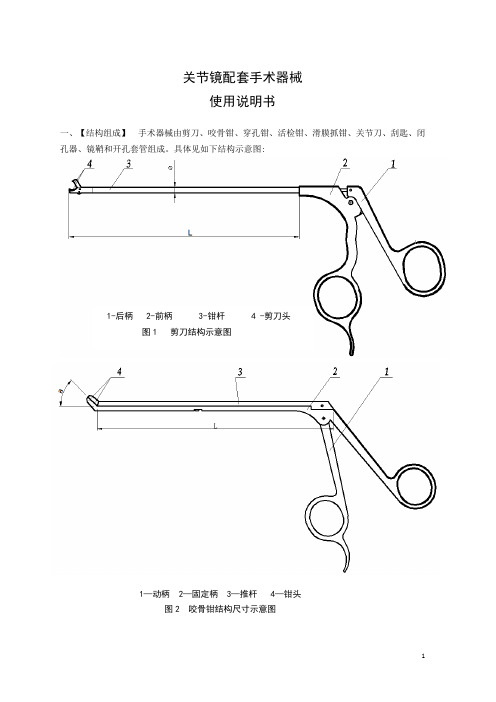
关节镜配套手术器械使用说明书一、【结构组成】手术器械由剪刀、咬骨钳、穿孔钳、活检钳、滑膜抓钳、关节刀、刮匙、闭孔器、镜鞘和开孔套管组成。
具体见如下结构示意图:1-后柄 2-前柄 3-钳杆 4 -剪刀头图1 剪刀结构示意图1—动柄 2—固定柄 3—推杆 4—钳头图2 咬骨钳结构尺寸示意图1—钳头 2—推杆 3—前柄 4—后柄图3 穿孔钳结构示意图1—后柄 2—前柄 3—钳杆 4—钳头图4 活检钳结构尺寸示意图1—基柄 2—动柄 3—推杆 4—钳头图5-1 135A型滑膜抓钳结构示意图1—动柄 2—基柄 3—钳杆 4—钳头图5-2 135B型滑膜抓钳结构示意图图6 关节刀结构尺寸示意图图7 刮匙结构尺寸示意图1—锁紧套 2—鞘座 3—阀门 4—套管图9 镜鞘结构尺寸示意图1—套管座 2—接座 3—接管图10 开孔套管结构尺寸示意图二、【适用范围】临床时在关节镜配合下,用于成人膝、肩和髋关节的诊断和手术治疗。
三、【主要性能参数】手术器械与人体组织接触的部件由符合GB1220-2007且用于医用的30Cr13、12Cr18Ni9、05Cr17Ni4Cu4Nb材料制成,具有良好的耐腐蚀性能;工作部位的表面粗糙度Ra参数值的最大数值为0.8um,其余最大值为1.6um。
剪刀、咬骨钳、穿孔钳、活检钳、滑膜抓钳、关节刀、刮匙的工作部位,经热处理后硬度规定为40-58HRC。
其余性能参数见表:表1 剪刀规格尺寸表单位:mm主要性能:1.剪刀头的动片、固定片应进行热处理,处理后的硬度规定为40-58HRC。
2.剪切刃口应锋利,有一定的剪切力,剪切后的断口应整齐。
3. 剪刀各连接部位应牢固可靠,焊缝应光滑平整,不得有堆焊、脱焊、虚焊现象。
表2 咬骨钳规格尺寸表主要性能:1.咬骨钳钳头动片应进行热处理,处理后的硬度规定为40-58HRC。
2.咬骨钳各连接部位应牢固可靠,焊缝应光滑平整,不得有堆焊、脱焊、虚焊现象。
3.咬骨钳应开闭灵活,松紧适度,不得有卡滞现象。
303E说明书-推荐下载

对全部高中资料试卷电气设备,在安装过程中以及安装结束后进行高中资料试卷调整试验;通电检查所有设备高中资料电试力卷保相护互装作置用调与试相技互术关,系电通,力1根保过据护管生高线产中0不工资仅艺料可高试以中卷解资配决料置吊试技顶卷术层要是配求指置,机不对组规电在范气进高设行中备继资进电料行保试空护卷载高问与中题带资2负料2,荷试而下卷且高总可中体保资配障料置2试时32卷,3各调需类控要管试在路验最习;大题对限到设度位备内。进来在行确管调保路整机敷使组设其高过在中程正资1常料中工试,况卷要下安加与全强过,看度并25工且52作尽22下可护都能1关可地于以缩管正小路常故高工障中作高资;中料对资试于料卷继试连电卷接保破管护坏口进范处行围理整,高核或中对者资定对料值某试,些卷审异弯核常扁与高度校中固对资定图料盒纸试位,卷置编工.写况保复进护杂行层设自防备动腐与处跨装理接置,地高尤线中其弯资要曲料避半试免径卷错标调误高试高等方中,案资要,料求编试技5写、卷术重电保交要气护底设设装。备备置管4高调、动线中试电作敷资高气,设料中课并技3试资件且、术卷料中拒管试试调绝路包验卷试动敷含方技作设线案术,技槽以来术、及避管系免架统不等启必多动要项方高方案中式;资,对料为整试解套卷决启突高动然中过停语程机文中。电高因气中此课资,件料电中试力管卷高壁电中薄气资、设料接备试口进卷不行保严调护等试装问工置题作调,并试合且技理进术利行,用过要管关求线运电敷行力设高保技中护术资装。料置线试做缆卷到敷技准设术确原指灵则导活:。。在对对分于于线调差盒试动处过保,程护当中装不高置同中高电资中压料资回试料路卷试交技卷叉术调时问试,题技应,术采作是用为指金调发属试电隔人机板员一进,变行需压隔要器开在组处事在理前发;掌生同握内一图部线纸故槽资障内料时,、,强设需电备要回制进路造行须厂外同家部时出电切具源断高高习中中题资资电料料源试试,卷卷线试切缆验除敷报从设告而完与采毕相用,关高要技中进术资行资料检料试查,卷和并主检且要测了保处解护理现装。场置设。备高中资料试卷布置情况与有关高中资料试卷电气系统接线等情况,然后根据规范与规程规定,制定设备调试高中资料试卷方案。
SECUMAX 320安全刀具说明书

SECUMAX 320NO. 32000110SAFETY KNIFE WITH CONCEALED BLADE, ESPECIALLY FOR CUTTING FILM AND PLASTIC STRAPPING BAND.Safety technologyTECHNICAL DATA SHEETOrder No. 32000110.02COMBI reloaded. The new generation.The SECUMAX COMBI was always in a class of its own as a film cutting expert – until it found its legitimate successor. The new SECUMAX 320 makes an instant impression with its outstanding design. And if you look more closely, you will appreciate its inner values. For example, in comparison to its predecessor, the perfected ergonomics and the completely overhauled blade change. What about the subject of …the highest level of work safety“? It has always been in the COM-BI’s DNA – and so it will remain that way.Safety firstThe concealed blade and rounded nose reliably protects you and your products. Furthermore, the knife head has been significantly strengthened making it more robust and longer lasting.Blade change made easyAnother benefit for handling and safety is the newly de-signed blade change. Simply lift up at the blade change but-ton and remove the cover. You can then directly access the 4-cutting edge blade.Perfect ergonomicsCan you feel the difference? The new handle shape with the finger friendly contours fits like a glove. The preset cutting angle is also kind to the hand and arm helping you to posi-tion the knife for cutting.Optimised blade areaJust two examples: The cutting channel is formed so that your safety knife moves away the freshly cut material even faster. Diagonal cuts are also easier than ever to perform. Your benefits: Less effort required for the task.Two splitting depthsWhen splitting tape, you now have a choice of depth be-tween 5 mm and 3.5 mm – for even more goods protection. Just open the handle, turn around the splitter, finished.Working with the splitter is just as uncomplicated. Pierce the tape and away you go.Concealed blade – a maximum degree of safetyThe SECUMAX 320 blade is not an open one, but is hidden from people andgoods. This provides you with a maximum degree of safety from cut injuries and from damage to goods.USAGEMain cutting materialsPRODUCT FEATURESTechnical featuresbutton.cover. Remove the blade from theside. Turn or change the blade.locating lugs.letting the blade change buttonaudibly snap into place.Maximum safety Safer blade change (withmagnet)Abrasion resistant Very ergonomic 4-times usable blade Cutting depth Tape splitter Soft-gripFor right and left hander Lanyard hole Printable for promotionalpurposesWrapping, stretch, andshrink foilLayers of foil or paper Plastic strapping band Cardboard: 1-ply Tape Bagged goods Textile, material FeltSafety belt Leather Coated film Laminated filmSAFETY CERTIFICATEPRODUCT AND PACKAGING DETAILSSECURITY ADVICETo ensure that you use your new MARTOR knife safely and most effectively, please read and note the following user-in-structions. Please keep the written guide in a safe place so that you can access it at any time.1. General application instructions: Please always use the product carefully for manual cutting work only and not for any purposes other than those that are intended. Please take the correct handling and the proper use of the knives into account in this regard. As an additional safety measure, we recommend the wearing of safe gloves.2. Special application instructions to avoid the danger of in-juries: Only use knives that are in perfect condition and have sharp, clean and undamaged MARTOR blades. Employ the utmost care when handling the knives. Prior to use, famil-iarise yourself with the safety features and their functioning. Ensure that these safety features are not impaired by the type of material to be cut. CAUTION: The blade is sharp and can result in serious and deep cuts. Therefore, never reach into the blade! Do not place your free hand in the line of cut-ting and never cut directly towards you.3. Replacement of spare parts: Replace any blades that be-come dull at the right time! Use only the replacement blades from MARTOR for this purpose. Dispose of old blades in aproper fashion. They should not be placed in a waste paper bin, as this poses a considerable danger of injuries. Never perform any repairs yourself. If the knife shows signs of aging or any other wear, e.g. which impair safety features, blade changing or usage, the knife must be taken out of service and replaced. Do not modify this product in any way. Modifications of any kind may impair product safety. CAU-TION: The risk of injury caused by manipulation of this prod-uct is extremely high.4. Non-use of the knife: Always secure the blade in such a way (depending on product type) that injuries due to cuts are excluded. Store the knife in a secure place.5. Care instructions: To guarantee a long service life, always keep the knife clean and do not expose it to unnecessary soiling and humidity.CAUTION: No liability will be assumed for consequential loss-es. Subject to technical changes and errors! This knife does not belong in the hands of children!SERVICES OFFEREDSafety posterTraining videoTechnical data sheetConsulting serviceACCESSORIES MANUFACTURERBELT HOLSTER M WITH CLIPNO. 9921What do you do with your cutting tools when you are not ac-tually using them? The MARTOR BELT HOLSTER M is a robust holder that allows you to carry all midsize MARTOR cutters as well as our safety scissors at all times. In addition, the inte-rior and exterior pockets are designed to allow you to load different tools: for example you can carry an extra cutter, a pen and a pack of blades. The MARTOR BELT HOLSTER is the ideal place to stow your tools safely when moving from A to B - and have them at hand, as soon as they are ED BLADE CONTAINERNO. 9810You can fill the USED BLADE CONTAINER with the content of your SAFEBOX. Or directly with your used blades. When the box is full, turn the lid until it shuts. Now the box cannot be reopened. The next step is to safely and completely dispose of the filled USED BLADE CONTAINER as normal waste.WALL MOUNT BRACKET USED BLADE CONTAINERNO. 9845Include it in your order now! With this mounting bracket you can fix your USED BLADE CONTAINER to a central location. Use the clamp and screws and nuts supplied with the prod-uct to attach it to either a pipe or a rod.SAFEBOXNO. 108000The SAFEBOX is large enough to store a large number of used blades safely. And at the same time, it is compactenough to carry with you. The two slits are not only used for filling, but also to …shorten“ your snap-off blades. When your SAFEBOX is full, empty it into your USED BLADE CONTAINER.MARTOR KG | Lindgesfeld 28 | 42653 Solingen | GermanyT+4921273870-0|F+4921273870-90|**************|。
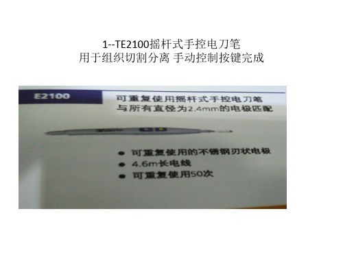
Ligasure刀头 - 副本
12--Wpsm256 (小 中 大号)
胃切除术
Gastroduodenal artery Hepatic artery proper Right gastric artery Hepatic artery Left gastric artery Short gastric arteries Splenlc artery Left gastroeplplolc artery Right gastroeplplolc artery Inferior pancreaticoduodenal artery Superior pancreaticoduodenal artery 胃十二指肠动脉 肝固有动脉 胃右动脉 肝动脉 胃左动脉 胃段动脉 脾动脉 胃网膜左动脉 胃网膜右动脉 胰腺下动脉
肾切除术
Aorta Interior vena cava Division of left renal artery
腹主动脉 下腔静脉 左肾动脉静脉分枝
Site of ligation and division of left renal vein
Line of dissection of kidney from adrenal vein Site of ligation and division of left adrenal vein Site of ligation and division of left gonadal vein Site of ureteral transection
8886848700Lapro-clip可重复使用单发施夹钳
该产品主要用于胆囊动脉和胆管的结扎及其它普通结扎术。性能及组成: 可吸收结扎夹与施夹钳配合使用,施夹钳主要有器械杆、握把构成,器械杆 材质为17-4PH(05Cr17Ni4Cu4Nb)不锈钢;可吸收结扎夹主要有内外两层结 构组成,外层夹的材料为聚甘醇酸,内层夹的材质为聚甘醇碳酸。施夹钳为 重复使用器械,使用前必须对其进行清洗和灭菌
303系列说明书

产品型号:303系列产品名称:多工位母线加工机合格证(HGZ)设备编号:检验员:本设备经检验合格济南力建数控设备有限公司制造检验技术指标对照表产品型号:303系列产品名称:多工位母线加工机使用说明书OPERATION MANUAL(SM)济南力建数控设备有限公司目录1.概述 (5)2.机器外形照片 (7)3.机器的基本参数 (12)4.机器的用途和特点 (13)5.机器的结构和原理 (14)6.机器安装和开机前的注意事项 (15)7.各单元的使用方法 (16)8.机器的液压系统 (21)9.机器的操作方法和电气的控制原理 (25)10.机器的常见故障和排除方法 (27)1 概述安全操作注意事项:操作前1.操作前使机器周围有一个安全的工作环境。
2.不要带围巾或穿大衣之类的衣服开机,以免危及人身安全。
3.用正确的方法进行工作,以便在发生故障时尽快停车和摆脱危险。
4.电源要求:三相四线380V±10%+PE。
5.如果环境温度低于10℃时,工作前应先开机空运转5分钟。
6.操作前,必须认真阅读本使用说明书,彻底熟悉机器的结构、性能和操作方法。
操作中1.安装、调试(对模、调整刀片间隙)或拆卸模具,必须由熟悉机器的人员按照规定的规程进行。
2.当机器开动时,切勿把手或身体的一部分放在上下模(刀片)之间,以免发生事故。
3.一切杂物及工具勿放在工作台上,以免轧入模具或刀口而造成事故。
4.由于本机器可多人操作,所以必须有专人负责指挥生产。
5.一定要根据铜排(或铝排)的厚度选择好剪切刀片和冲模的间隙及折弯圆角半径。
6.在更换模具时一定要停机,以免发生危险。
7.在操作时,拿着工件等待滑块下行时必须小心。
8.应定期检查刀片和冲模刃口锋利程度,如发现刃口用钝,应及时修磨或更换。
9.保持油液清洁及油路畅通,每班给各单元运动部件加油。
10.电气与液压元件必须保证动作灵活与位置正确,发现不正常现象时必须立即停车检查。
操作后操作完后,一定要按下列顺序安全关机:(1)关断各单元工作按钮。
高频电刀技术要求
采用AEC五个电离室自动曝光控制系统
8.4
胸片架滤线器为活动滤线栅非固定滤线栅
栅比为≥8:1栅密度≥36lp/cm
8.5
球管与探测器运动定位功能:平衡式运动,电磁式安全刹车,与球管同步自动跟踪,自动(电动)定位和手动定位;
8.6
SID(片源距)自动测量和指示,SID110-180的摄影范围
8.7
4.2
球管具有和探测器同步自动跟踪自动(电动)定位和手动定位功能
4.3
阳极旋转≥9000转/分钟
4.4
阳极热容量≥300KHU
*4.5
双焦点≤0.6/1.2mm
4.6
焦点功率≥33/100KW
4.7
自动缩光器,可根据检查类型自动设定照射野。
4.8
请提供球管质保期后单价。
五、
高压发生器
5.1
高频逆变式X线发生器:输出功率≥60KW;频率≥20KHZ
7.11
可分别调整肺野和纵隔的密度,调整图像的大体对比度和图象细节对比度
7.12
具有调节亮度、对比度调整、边缘增强等功能
7.13
具有电子光栅:可将图像中的无用部分隐去,使用图像更加美观
7.14
图像放大功能:可放大5倍以上
7.15
图像旋转功能有:能提供上下、左右/逆时针90°/顺时针90°旋转功能
7.16
十、
图像处理工作站(品牌商用机)
10.1
CPU:主频>3.0 GHZ
10.2
内存:>2GB
10.3
硬盘容量:>120GB
10.4
网卡:100MB/S
10.5
DVD刻录机
10.6
显示器:专业医用显示器1兆以上
手术室高频电刀操作规程

高频电刀操作规程高频电刀是一种取代机械手术刀进行组织切割的电外科器械。
它通过有效电极尖端产生的高频高压电流与肌体接触时对组织进行加热,实现对肌体组织的分离和凝固,从而起到切割和止血的目的。
高频电刀是由主机和电刀刀柄、负极板、双极镶、脚踏开关等附件组成的,有两种主要的工作模式:单极和双极。
(一)单极电刀(monopolarelectricalcautery)【工作原理】利用RF射频原理,使其输出的300〜500HZ高频电流释放的热能和放电对组织进行切割、止血。
其理论基础是焦耳定律。
电流在电刀的刀尖形成高温、热能和放电,使接触的组织快速脱水、分解、蒸发、血液凝固,实现分解组织和凝血作用,达到切割、止血的目的。
人体组织吸收的热量和温度升高与电极和组织的接触面积成反比。
【操作流程】(1)评估患者:患者是否佩戴金属首饰及手表,有无金属植入物,是否安装永久性心脏起搏器等。
患者身体是否接触手术床及其他装置的金属部分。
手术台上的敷料是否干燥,手术床垫是否干燥、绝缘。
(2)检查仪器设备是否完好,检查电刀附件是否齐全。
(3)接通电源,打开仪器开关,仪器完成自检。
(4)连接电极板,将负极板黏贴于肌肉丰富处,长方形负极板的长边与身体纵轴垂直。
(5)选择合适的输出功率及输出模式,一般手术输出功率为30~70W0(6)洗手护士将单极电刀固定于手术台,勿缠绕固定在金属器械上,主机接口端传递给巡回护士将其插入高频电刀对应插口。
(7)术中应及时用电刀清洁器清除电刀头上的焦痂;暂时不用时,将电刀头放置于绝缘的保护套内;发现电刀头功能不良时应及时更换。
(8)手术结束后先关主机电源开关,拔出单极电凝线,按正确方法撕除电极板,再拔电源线,清洁整理电刀设备。
【注意事项】(1)选择合适的电极板:使用分散电极;使用高质量的电极板;电极板一次性使用;尽可能使用软极板;体重15kg以下的小儿,应选择婴幼儿电极板或新生儿电极板;禁止裁剪,且要求黏性强并容易撕脱;应使用双箔负极板。
PSE-303操作说明书

Setting ProceduresInitializebutton when [Sor] is1.Display Color SettingSelect a color for the LCD display.When changing the display color,to select a display color.desired display color.2.Output linked to display color Settingbutton and select output.Press to set.3.Pressure Range Settingbutton and select thebutton to set.4. Selecting Display Unit (In case [-M] is not assigned to unit specification in model indication)Refer to page 17, “Selecting Display Unit”.Unit LabelHow to use the labels printed the unitsIn order to display the selected unit, the unit label according to the pressure range or the display unit is attached.•In case [M] is assigned to unit specification in model indication.•In case [M] is not assigned to unit specification in model indication.5. Output Method Setting•Four output mode can be selected by an operating mode and by output style. One of these four output mode can be selected for each output.•OUT1 and OUT2 can be set independently.•Refer to Output Mode Selection on next page.1) The operating mode for OUT1 is set.•button and select the hysteresis mode or the•Press to set.•button and select the normally open or the•Press to set.•Press and to set, as in OUT1.•When setting in the Auto Presetting mode, the Hysteresis mode will be set automatically.•The following is given using OUT1 as an example. The descriptions for OUT2 are the same as those for OUT1, under the conditions that [n_1] and [n_2] should be replaced by [n_3] and [n_4] , [P_1] and [P_2] should be replaced by [P_3] and [P_4] and [H_1] should be replaced by [H_2].6.Response Time Setting•A response time for switch output can be set as user desires.•Set the optimum response time to prevent the chattering of a switch.orto set .7.Pressure setting•There are two methods for pressure set-up : manual and auto preset,either one of which can be selected. The auto preset is provided for anautomatic optimum set-up by using a sample for a case in which switchoutput is used to check absorption.•or button to select the set-up methodPress to set.8.Auto Shift setting (PSE302 / 305 model only)1) Select the display mode of the pressure value at the time of auto shiftoperation.Either [AS (Auto Shift)] or [ASO (Auto Shift Zero)] can be selected.AS (Auto Shift) : [AS] displays the differential pressure of the atmosphere and measurement pressure.ASO (Auto Shift Zero) : [ASO] displays the differential pressure of the measurement pressure and the •Press to select the Auto Shift or Auto Shift zero. Press to set.2) Selecting the switches which Auto Shift mode apply,•Press to select the A1, A2 or Ab. Press to set.•The initialize setting will be completed and return to the Measurement mode.Manual SettingManually set a set value of the controller.•button during the Measurement mode to display set values.•(In case the Normally Closed mode is selected in initialization, [n_1]•button to enter into the Value Changing mode,•button to set the set value.2. Selection of OUT1 [P_2] setting mode•[P_2] and the current set value will flicker alternately.(In case the Normally Closed mode selected in initialization, [n_2] and •button to enter into the Value Changing mode,•button to set the set value.3.Selection of OUT1 [H_1] setting mode••button to enter into the Value Changing mode,•button to set the set value.4.Selection of OUT2 setting modeSet the set values [P_3] [P_4] and [H_2] of OUT2 as in OUT1.[P_3] [P_4] or [H_2] and current set value will flicker alternately.(In case the Normally Closed mode selected in initialization, [n_3] [n_4] or [H_2] and set value will flicker alternately)•button to enter into the Value Changing mode, •button to set the set value.5. Auto shift compensation value setting (PSE302 / 305 model only)••button.•Auto Preset SettingIn case auto preset is selected in Initialize, this function stores in the memory a pressure setting value which is calculated from a measurement pressure as a reference value. The set value of controller is automatically set to an optimum value by repeating absorption and non-absorption several times with a sample which is to be set up.•Press to display [AP1].button at the same time longer than onesecond.)2.Preparation of unit for OUT1Prepare a unit for which pressure for OUT1 is to be set.•Press to display [A1L].••Detection will be made and a set value will be stored in the memoryautomatically and display [A1H].••button at the same time longer than one second.)5.Preparation of unit for OUT2 and pressure setting••Press to display [A2L].•display [A2H].•button to set the set value of [P_3],[P_4] ([n_3],[n_4] in Normally Closed mode), and auto•The mode will return to the Measurement mode.A pressure setting value in auto preset is as follows in Normally Open mode with OUT1.(P_1 is n_1 in Normally Closed mode with OUT1.)P_1 = A – (A – B)/4 A = maximum pressure valueH_1 = (A – B)/2 B = minimum pressure valueFor OUT2 set-up, above P_1, n_1, and H_1 become P_3, n_3, and H_2 respectively.Auto shift functionIn case the source pressure fluctuates too much, the controller may not be able to operate normally. Auto shift is provided to compensate for the fluctuation of the source pressure.While measured pressure becomes standard pressure value when auto shift input is received, this function correct set value of the switches.With Auto ShiftSet auto shift input as Lo at the time pressure source change, in order to memorize the pressure change and to correct pressure set value, so that correct decision emerge.Conditions and explanations for auto shift function•Keep constant pressure for 5ms or more from the close signal of auto shift input.•At auto shift input, the pressure at that time is memorized to [C_5] as corrected value, and the switch operates with the value which applied compensation value to setting value.Display indicates [ooo] for approx.1 sec.•The switch set as auto shift mode at the time of initial setting operates with the value which applied corrected value [C_5] to setting value.•OUT1 will operate with Auto shift function, when “A1” is selected.The operating value of OUT1 applies corrected value [C_5] to [P_1],[P_2] or [n_1],[n_2].•OUT2 will operate with Auto shift function, when “A2” is selected.The operating value of OUT2 applies corrected value [P_3],[P_4] or [n_3],[n_4].•Both OUT1 and OUT2 will operate with Auto shift function, when “Ab” is selected.The operating value of OUT1 and OUT2 applies corrected value [P_1] to [P_4] or [n_1] to [n_4].•Span is 10ms or less until switch output perform soon after auto shift input.•When corrected set value exceed the set pressure range with auto shift input, corrected value is not memorized and displays [o.r] for approx.1sec.•Correct value [C_5] after auto shift input vanish when off the power.•Correct value [C_5] for auto shift input function is reset as zero (Initial value) when re-supplied power.•In case of auto shift zero selected, the display indicates [0] (zero)] if the auto shift signal is inputted.Note: No EEPROM in the memory of corrected value.Peak and Bottom Hold Display Function•button again for more than one second. The measurement mode will be set.•button again more than one second. The Measurement mode will be set.•Key Lock FunctionThis function prevents errors such as changing a set value by mistake.Lock•displayed.•Presstoset the display to [LoC].•Unlock••buttons to change the display to [unL].•Zero Clear FunctionA displayed value can be adjusted to zero when pressure to be measured is within ±7%F.S. of the atmospheric±4digits according to a product characteristic.)•buttons simultaneously more than one second to reset to “0” on the display.•The mode will return to the Measurement mode automatically.Error Display FunctionThis function displays error location and nature when a problem or an error occurs.。
r-S330M-说明书

schneider ATV303通用型变频器 说明书

ATV32
ATV 21
请参考“ATV 32 变频器” 产品目录
请参考“ATV 21 变频器” 产品目录
0.37...2400 – 0.37...5.5 – 0.75...90 0.75...1400 – – 2.2...2400
0.5...500 Hz,用于整个系列 0.5...1000 Hz,在 200...240 V a 与 380...480 V a 时最高至 37 kW Kn2 二次比 无传感器的磁通矢量控制 电压/频率比 (2 或 5 个点) 能量节省比
ATV 61
请参考“ATV 61 变频器” 产品目录
ATV 71
请参考“ATV 71 变频器” 产品目录
3
介绍
4
变频器
ATV303
产品介绍
ATV303变频器是针对三相电压为380V(-15%)...460V(+10%)的异步电机而设计的, 功率范围是0.37kW至11kW。
ATV303 变频器的设计从以下方面考虑而实现即插即用: b 紧凑的尺寸 b 集成的功能 b 优化的电机控制 b 宏配置功能
变频器
输出频率
控制类型
异步电机
瞬时过转矩
同步电机
功能 功能数量 预置速度的数量 I/O数量
通讯
模拟输入 逻辑输入 模拟输出 逻辑输出 继电器输出
集成通讯协议 可选配件
卡 (可选配件) 标准与认证
型号 页码
2
0.18...4 0.18...0.75 0.18...2.2 – 0.18...4 – – – –
3
2
Modbus和CANopen-Bluetooth®link
DeviceNet, PROFIBUS DP V1, EtherNet/IP, Modbus TCP, EtherCat
高频电刀使用说明书

SERVOTOME Classic 高频电刀使用说明书法国赛特力公司SERVOTOME CLASSIC高频电刀使用说明目录配置说明-随机配件 2 -面板 2 -背板 2 -技术数据 3 安装-连接 3开机 3保养-更换保险 4 使用建议 4 故障的排除 5 售后服务 6随机主要配件●1个脚闸开关及其连接线(2米长)(图1-①)●1条可摘电源线(2米长) 220V +接地线(图1-②)●1个电极手柄+连接线(2米长)(图1-③)●1个中性极板+连线(2米长)(图1 -④)●1盒10支可消毒电极和使用调节表结构介绍SERVOTOME 面板:①电源开关(I/o)②绿色电源指示灯③功率调节旋钮④黄色工作指示灯,机器工作时伴有蜂鸣音⑤电凝调节旋钮*切割模式切割+中度电凝切割+强电凝⑥电极柄连线插座* 电凝效果与电极直径有关,请参阅临床手册:I 58703SERVOTOME的背板(图4)①中性极板插座②脚闸插座③主电源插座④保险丝座技术特点:高频电外科设备电源电压:50/60 Hz,230V保险丝:Type 5×20mm220V 2×1AT最大功率消耗:220VA1级设备— BF型工作间歇:工作10s/30s输出功率:42W + 20%输出频率:1.8MHz+0.7外形体积:长:170mm宽:140mm高:65mm安装连接:提示:如果与当地电源不匹配,请找专业电工帮助,连接至当地电源,然后进行以下连接。
SERVOTOME 面板的各项连接(图6)* 将电极柄连线接入插座①SERVOTOME 背板的各项连接(图7)* 将中性极板连线接入插座①* 将脚踏开关连线接入插座②* 将主电源线接入插座③。
电源线必须插在接地线的电源插座上。
机器上的电源插座内有两个保险开机:- 机器必须连接于接地线的电源上- 将电极固定在电极柄上-中性极板放在病人后背与椅背之间。
留意中性极板上印有“PATIENT SIDE”为朝向病人的一面- 将开关键①置于“I”的位置,绿灯亮,显示已打开- 调节功率③和凝血⑤- 踩脚闸,黄灯亮伴随蜂音,此时处于切割状态,松开脚闸停止切割注意:间歇时间应为工作时间的3倍。
innoflame 电火器操作手册说明书
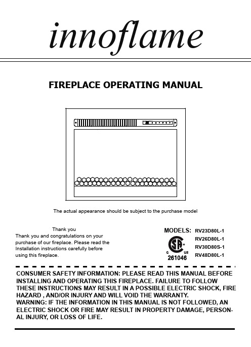
FIREPLACE OPERATING MANUALCONSUMER SAFETY INFORMATION: PLEASE READ THIS MANUAL BEFORE INSTALLING AND OPERATING THIS FIREPLACE. FAILURE TO FOLLOWTHESE INSTRUCTIONS MAY RESULT IN A POSSIBLE ELECTRIC SHOCK, FIRE HAZARD , AND/OR INJURY AND WILL VOID THE WARRANTY.WARNING: IF THE INFORMATION IN THIS MANUAL IS NOT FOLLOWED, AN ELECTRIC SHOCK OR FIRE MAY RESULT IN PROPERTY DAMAGE, PERSON-AL INJURY, OR LOSS OF LIFE.Thank youThank you and congratulations on your purchase of our fireplace. Please read the Installation instructions carefully before using this fireplace.MODELS:innoflameRV23D80L-1RV26D80L-1RV30D80S-1RV48D80L-1The actual appearance should be subject to the purchase modelIMPORTANT INSTRUCTIONSWhen using fireplace, basic precautions should always be followed to reduce the risk of fire, electri-cal shock, and/or injury including the following:1. Read all instructions before using this fireplace.2. This fireplace is hot when in use. To avoid burns, do not let bare skin touch hot surfaces. If provid-ed, use handles when moving this fireplace.DANGER: High temperature may be generated under certain abnormal conditions. Do not partially or fully cover or obstruct the front of the fireplace.WARNING: In order to avoid overheating, do not cover the fireplace. It cannot be used in a closet.3. CAUTION: The fireplace should not be used by children or persons with reduced physical, senso-ry or mental capabilities.4. Children should be advised not to play with the fireplace.5. The fireplace is suitable for using in a recreational vehicle.6. Do not operate any fireplace with a damaged cord or plug or after the fireplace malfunctions, or if it has been dropped or damaged in any manner.7. If the supply cord is damaged, it must be replaced by the manufacturer, it’s service agent or simi-larly qualified persons in order to avoid a hazard.8. Any repairs to this fireplace should be carried out by a qualified electrician.9. Under no circumstances should this fireplace be modified. Parts having to be removed for servic-ing must be replaced prior to operating this fireplace again.10. Do not use outdoors.11. This fireplace is not intended for use in bathrooms, laundry areas and similar indoor locations. Never locate this fireplace where it may fall into a bathtub or other water container.12. Do not run cord under carpeting. Do not cover cord with throw rugs, runners or the like. Arrange cord away from traffic areas and where it will not be tripped over.13. To disconnect this fireplace, turn controls to the off position, then remove plug from outlet.14. Connect to properly grounded outlet only.15. This fireplace, when installed, must be electrically grounded in accordance with local codes or, in the absence of local codes, with the current CSA C22.1 Canadian Electrical Code or for USA installations, follow local codes and the National Electrical Code, ANSI/NFPA NO.70.16. There is a protective thermostat limiter inside the fireplace. When the inner temperature over heat, the thermostat limiter will shut off the power supply to avoid the risk of fire damage to the fireplace.17. The fireplace must not be located immediately below a socket-outlet.18. Do not insert or allow foreign objects to enter any ventilation or exhaust opening as this may cause an electric shock or fire, or damage to the fireplace.19. To prevent a possible fire, do not block air intakes or exhaust in any manner. Do not use on soft surfaces, like bed, where opening may become blocked20. This fireplace has hot and arcing or sparking parts inside. Do not use where gasoline, paint, or flammable liquids are used or stored. This fireplace should not be used as a drying rack for clothing. Christmas stockings or decorations should not be hung in area of it.21. Use this fireplace only as described in the manual. Any other use not recommended by the man-ufacturer may cause fire, electric shock or injury to persons.22. Always plug fireplace directly into a wall outlet/receptacle. Never use with an extension cord or relocatable power tap (outlet/power strip).SAVE THESE INSTRUCTIONSINSTALLATION INSTRUCTIONSFireplace DimensionsCabinet DimensionsElectrical Specifications120V 60Hz 1400WGrounding Instructions:RV48D80L-1RV48D80L-1RV30D80S-1Figure 141”41.5”6.2”18.3”4.7”18.1”RV30D80S-129.2”29.7” 6.2”14.9” 4.7”14.7”This fireplace is for use on 120 volt circuits. The cord has a plug as shown at (A) in figure 1.An adapter as shown at (C) is available for connecting three-blade grounding-type plugs to two-slot receptacles. The green grounding lug extending from the adapter must be connected to a permanent ground such as a prop-erly grounded outlet box. The adapter should not be used if a three-slot grounded receptacle is available.NOTE: Adapters are NOT for use in CanadaModel NO.W D H RV23D80L-1RV26D80L-1Model NO.W D H RV23D80L-1RV26D80L-121.9”22.3” 6.2”18.3”18.3”6.2” 4.7”18.1”18.1”4.7”25.1”25.5”WARNING: Cabinet construction and electrical outlet wiring must comply with local bulding codes regulations to reduce the risk of fire, electrical shock and injury to persons.OPERATING INSTRUCTIONSThe Power ButtonThe power button turns the fireplace on & off. When the fireplace is off pressing the power button once will switch on the fireplace. Once on, if the fireplace display is not illuminated pressing the power button will light up the display. If the power button is pressed again within 10 seconds it will turn off the fireplace. If the display is already illuminated then only one press of the power button is needed to turn off the fireplace.The power button has a built in memory function that will retain the status of the fireplace when turned off. With the exception of the timer, the fireplace will restart in its previous status. If the fireplace is disconnected from the main power source it will lose the memory and restart at the default settings.The Flame ButtonEach time the Flame Button is pressed, the color of the flame changes. There are 7 colors, dynamic condition ,and the OFF setting you can cycle through.The Heater ButtonThe Heater Button turns the heater On & Off. When the heater is on, press the Increase/Decrease button to change the desired temperature. There are 11 temperature settings: 72℉-74℉-76℉-78℉-80℉-82℉-ON-64℉---72℉(22℃-23℃- 24℃-25℃-26℃-27℃-ON-18℃---22℃).Temperature unit convert function: When the heater is on, press and hold the Power Button for 5 seconds, current temperature unit display will flash 3 timers and convert to another temperature unit (Note: This can't be set with the remote control).Lock & unlock heater function: press and hold the Heater Button for 10 seconds, the ember bed will flash 6 times, indicating that the heater function is locked. To unlock the heater function, just repress and hold the heater icon for 10 seconds again, then the ember bed will also flash 6 times indicating the heater function is unlocked and to recover the original states which you have set.(Note: This can't be set with the remote control).CONTROL PANELControl panel can be access at upper-right corner of the fireplace.NOTE: The remote control is intended only for the functional operation of the product, It can not lock/unlock the heating function !The Timer ButtonThe TIMER has adjustable setting with range from 30 minutes to 6 hours and OFF. As shown the following: 30 minutes- 1h-2h-3h-4h-5h-6h-OFF. Once you have set the timer, and the timer is up, the ember bed will flash 6 timers and close all the functions and enter standby mode. In this mode, you should touch the power icon to restart the fireplace.The Ember Bed ButtonEach time the Ember Bed Button is pressed, the color of the ember bed changes. There are 7 colors and dynamic condition you can cycle through.The Increase/Decrease ButtonThis button is only used to setting the temperature.BATTERY REPLACEMENTBATTERY DISPOSALNOTE:Do not mix old and new batteries. Do not mix alkaine, standard (carbon zinc), or rechargable (nicad, nimh, etc.) batteries. Do not ingest batteries.Always purchase the correct size and grade of battery most suitable for the intended use. Replace all batteries of a set at the same time.Clean the battery contacts and also those of the device prior to battery installation. Ensure the batteries are installed correctly with regard to polarity (+ and -).Remove batteries from equipment which is not to be used for an extended period of time.Battery may contain hazardous substances which could endanger the environment and human health. This symbol marked on the battery and/ or packaging indicates that used battery shall not be treated as municipal waste. Batteries should be disposed of at an appropriate collection point for recycling. By ensuring the used batteries are disposed of correctly, you will help preventing potential negative consequences for the environ-ment and human health. The recycling of materials will help to conserve natural resources. For more information about recycling of used batteries, please contact your local municipality waste disposal serviceCARE AND MAINTENANCETROUBLESHOOTINGIMPORTANT:▪ Always unplug the power cord before cleaning the fireplace. Allow the unit to cool before cleaning it.▪ Wipe the exterior surface of the fireplace occasionally with a soft, damp cloth (not dripping wet), and dry the exterior surface before operating. ▪ Do not immerse the fireplace in water.▪ Do not use any cleaning chemicals such as detergents and abrasives.▪ Do not allow the interior to get wet, as this could create a hazard.▪ Light accumulated dust may be removed from the fireplace with a soft, dry cloth.▪ To store the fireplace, put it back into its original packaging and store in a clean, dry place.▪ The blower and flame motor are pre-lubricated for a durable using time and need no further lubrication or maintenance. Dust particles will accumulate on/in the fireplace, so periodic clean-ing/vacuuming of the fireplace is recommended.Fault codeFault CauseSolutionE1The overheatingCall service.E2NTC is defective.E3The not working.If the vents are dirty or clogged.Unplug the power,clean the dust and debri of the vent area.Wait for 5minutes,plug in and turn on the .If the heater still work,please call service.heater is heater dealer for Call service.dealer for dealer for heater does notCIRCUIT DIAGRAMRV23D80L-1 & RV26D80L-1 & RV30D80S-1 CIRCUIT DIAGRAMRV48D80L-1 CIRCUIT DIAGRAMMade in ChinaPrinted in China。
热能刀资料

美国斯塔龙电热能手术系统(热能刀)产品简介一种新型使用热能和压力同时切割和封闭血管或其它组织的新型手术设备,由美国哥伦比亚大学手术系和美国starion instruments设备公司开发制造。
公司的专利技术-“组织焊接技术”应用于包括普外科、耳鼻喉科和心胸外科在内的很多手术设备上,外科医生可利用此项技术,闭合和分离软组织。
由于组织焊接技术不使用射频能量,所以它既提高手术质量,又不会造成组织损伤。
它是能够让外科医生除选择双极电刀和超声刀凝血、封闭组织的仪器之外,在技术方面的又一个选择。
这种新型手术设备高效的直热式技术可以作为止血和切割方式的有效替代,特别是用于要明显减低对周围组织最低的侧面损伤的情况电热能手术系统(热能刀)与电刀比较starion热能刀组织损伤最小(热传导小于0.861mm)没有电流通过手术部位,不受限制同时切割组织和封闭血管,无粘刀、炭化、焦痂。
视野清晰无烟雾,安全可靠,体积小,节省空间,便于携带。
电刀热损伤范围广(大于3mm),多余的热能对柔弱的器官和组织有潜在热损伤的危险。
有电流通过,腹腔镜外科手术中,由于可见度差,导致局部和远端的电损伤。
对电敏感的器官,如神经、心脏、脑等,电刀有局限性。
电刀也有禁忌症:对电敏感的部位不能手术(如心脏、神经组织);不能同时切割组织和封闭血管,封闭血管小且效果不切实粘刀,炭化和焦痂现象。
易再出血,有大量烟雾,视野不清晰,体积大。
电热能手术系统(热能starion热能刀)无极纯热,无电热传导损伤小(平均小于0.861mm);同时切割组织和封闭血管(靠瞬间集中最小范围高热能切割);器械多样化;设计精巧,满足多学科各种精细解剖;应用范围广;便宜;设计紧凑。
starion热能刀与ligasure比较starion热能刀无极纯热,无电热传导损伤小(平均小于0.861mm),同时切割组织和封闭血管(靠瞬间集中最小范围高热能切割);器械多样化;设计精巧,满足多学科各种精细解剖;应用范围广;便宜;设计紧凑。
一、高频电刀性能及技术参数要求
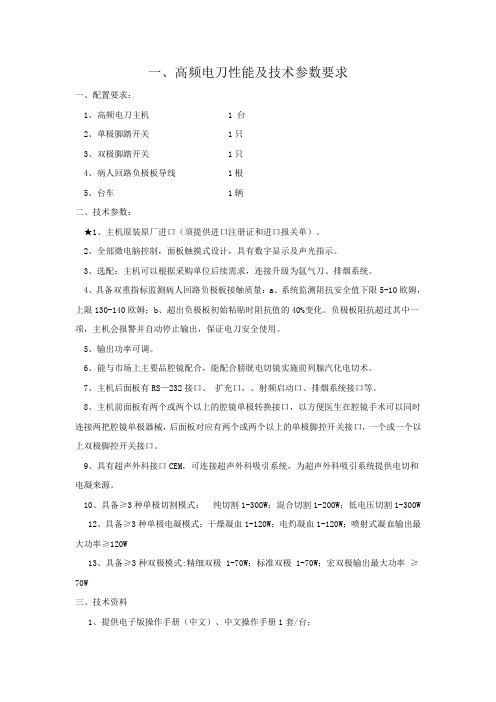
一、高频电刀性能及技术参数要求一、配置要求:1、高频电刀主机 1 台2、单极脚踏开关 1只3、双极脚踏开关 1只4、病人回路负极板导线 1根5、台车 1辆二、技术参数:★1、主机原装原厂进口(须提供进口注册证和进口报关单)。
2、全部微电脑控制,面板触摸式设计,具有数字显示及声光指示。
3、选配:主机可以根据采购单位后续需求,连接升级为氩气刀、排烟系统。
4、具备双重指标监测病人回路负极板接触质量:a、系统监测阻抗安全值下限5-10欧姆,上限130-140欧姆;b、超出负极板初始粘贴时阻抗值的40%变化。
负极板阻抗超过其中一项,主机会报警并自动停止输出,保证电刀安全使用。
5、输出功率可调。
6、能与市场上主要品腔镜配合,能配合膀胱电切镜实施前列腺汽化电切术。
7、主机后面板有RS—232接口、扩充口,、射频启动口、排烟系统接口等。
8、主机前面板有两个或两个以上的腔镜单极转换接口,以方便医生在腔镜手术可以同时连接两把腔镜单极器械,后面板对应有两个或两个以上的单极脚控开关接口,一个或一个以上双极脚控开关接口。
9、具有超声外科接口CEM,可连接超声外科吸引系统,为超声外科吸引系统提供电切和电凝来源。
10、具备≥3种单极切割模式:纯切割1-300W;混合切割1-200W;低电压切割1-300W 12、具备≥3种单极电凝模式:干燥凝血1-120W;电灼凝血1-120W;喷射式凝血输出最大功率≥120W13、具备≥3种双极模式:精细双极 1-70W;标准双极 1-70W;宏双极输出最大功率≥70W三、技术资料1、提供电子版操作手册(中文)、中文操作手册1套/台;2、提供维修手册:包括线路图、电路板位置图、检测、调试方法、故障代码等(可以是电子版或光盘)四、售后服务要求(实质性响应条款):1、整机(含电脑等)保修≥1年;装机合格后使用寿命≥7年;维修、维护及配件,厂方终身提供(终身指使用单位未报废处理之前),出保后收费不得高于市场价格。
电刀的使用

电刀的使用电刀的使用手册1-引言1-1 本文档旨在提供电刀的详细使用说明,以确保用户正确、安全地使用电刀。
1-2 电刀是一种高频电切工具,主要用于医疗手术中的切割和凝固操作。
2-术语定义2-1 电刀:一种通过高频电流产生热能并将其传递给手术刀具的医疗器械。
2-2 切割:使用电刀进行组织切割的操作。
2-3 凝固:使用电刀进行血管封闭等操作,以达到止血和减少出血的目的。
2-4 高频电流:频率超过100,000赫兹的电流。
3-电刀使用前的准备3-1 检查器械:确认电刀及相关配件是否完好,如电极、电缆等。
3-2 电源连接:将电刀正确连接到电源并确保电源供应稳定。
3-3 操作区域准备:清洁工作区域并将需要使用的器械、药品等准备好。
4-切割操作步骤4-1 确定切割位置:根据手术需要确定要切割的组织位置。
4-2 选择电刀电极:根据手术需要选择合适的电刀电极,如剑形电极、球形电极等。
4-3 设置电刀功率:根据组织性质和手术要求设置电刀的功率。
4-4 切割操作:将电刀电极与组织接触并进行切割操作,注意保持电极清洁和持续水冷却。
4-5 切割完毕:切割操作完成后,关闭电刀电源并将电刀电极进行清洁和消毒处理。
5-凝固操作步骤5-1 确定凝固位置:根据手术需要确定要凝固的血管位置。
5-2 选择电刀电极:根据手术需要选择适合的电刀电极,如细电极、钳形电极等。
5-3 设置电刀功率:根据血管大小和手术要求设置电刀的功率。
5-4 凝固操作:将电刀电极与血管接触并进行凝固操作,注意保持电极清洁和持续水冷却。
5-5 凝固完毕:凝固操作完成后,关闭电刀电源并将电刀电极进行清洁和消毒处理。
6-安全注意事项6-1 仅限专业人员操作:电刀操作应由经过相关培训的医护人员进行。
6-2 注意电刀功率:根据实际情况调整电刀功率,避免对组织造成不必要的损伤。
6-3 避免电刀电极碰撞:电刀电极碰撞可能导致电刀短路或器械损坏,需谨慎操作。
6-4 维护保养:定期清洁和维护电刀及相关设备,确保其正常工作。
Arcair SLICE 热切割设备操作指南说明书

Exothermic Cutting Equipment - Cutting Rods
Uncoated/Coated • Uncoated rods are used in applications when
igniting with a battery source • Coated rods are used when cutting with DC
Blue 3 meter industrial gas hose.
Exothermic Cutting Equipment - SLICE® Torch
Spark arrestor are included in all SLICE torch kits for safety reasons. The location of these require relocating when using the torch extension.
EXOTHERMIC CUTTING
EQUIPMENT
Objectives
By the end of this session, you will be able to: • Identify the difference between the Arcair packages that are available to EU customers. • Recognise the main components within the Arcair SLICE® package. • Demonstrate how to correctly assemble Arcair equipment, initiate the arc and complete various cuts using various ‘setups’. • Understand how to maintain the equipment before, whilst in use and post cutting application.
带你了解高频电刀的使用(附精彩视频)

带你了解高频电刀的使用(附精彩视频)有关于高频电及参数的内容有专题学习过了,今天就与高频电发生器相连接的电刀做一次学习,主要是ESD所用的电刀。
分为常用电刀和前沿电刀两大类。
针对刀的参数简单了解胃肠用不同种类,是否刀头长度可调节,是否可旋转,是否可同时注射等。
来源:医学界消化频道(内镜学习驿站出品)作者:薛润国苏彬承德市中心医院内镜室审稿:赵洪礼海博刀发生器和电刀一、常用电刀IT刀家族1994年日本学者发明首次使用IT刀并应用到ESD操作以来已经有20多年了,设计的目的是为了防止电刀对粘膜下层的意外损伤甚至是电刀造成消化道穿孔穿孔。
IT刀即insulated tip,尖端绝缘的意思,这个刀的出现,使ESD 的剥离更加安全,也使ESD的操作技术有了突破式的发展。
经过多年的发展和产品改进,逐渐出现IT1代和2代,甚至是ITnano。
nano的出现解决了1、2代IT刀在狭小的粘膜下层空间中因绝缘帽过大而操作不够灵活的不足。
1代IT刀主要的设计要点就是在刀头前端增加了绝缘帽,为半球形陶瓷帽。
既能防止深部粘膜损伤也能使刀在粘膜下层能够较好的活动。
刀头长度可控,导丝长度为4mm。
2代IT刀在半球形陶瓷帽的内侧置放3个电极,使IT刀的横向切开速度更快。
刀头长度可控,刀丝长度'4mm+0.7mm*3'。
IT-nano将1代IT尖端帽的“帽子”缩小,即IT-nano(记不记得苹果公司的Ipod-nano,就是这个词)。
由于绝缘帽变得“瘦小”,在粘膜下层进行剥离和移动变得比较灵活,而且较1、2代IT刀更加容易“钻进”黏膜下层,方便操作医生进行ESD剥离操作。
勾刀:即HOOK刀。
先端采用L 型设计,勾住组织纤维后实施剥离。
由于勾住组织后向上挑起,不会侵入更深的组织,避免穿孔。
虽如此说,但在实际使用时由于刀头前端没有绝缘保护,进行剥离时还是风险比较大,稍有不慎容易切破肌层甚至是穿孔,所以需要经验丰富的医生进行操作。
- 1、下载文档前请自行甄别文档内容的完整性,平台不提供额外的编辑、内容补充、找答案等附加服务。
- 2、"仅部分预览"的文档,不可在线预览部分如存在完整性等问题,可反馈申请退款(可完整预览的文档不适用该条件!)。
- 3、如文档侵犯您的权益,请联系客服反馈,我们会尽快为您处理(人工客服工作时间:9:00-18:30)。
arc303电刀说明书
ARC303 电刀说明书感谢您选择使用ARC303电刀。
本说
明书将为您提供有关电刀的详细信息和正确使用方法,以
确保您的安全和最佳使用体验。
1. 产品概述\nARC303电刀
是一款高性能的厨房工具,专为快速、精确地处理食材而
设计。
它采用先进的电动技术,具有强大的切割能力和稳
定性。
2. 安全操作\n- 在使用前,请确保插头与插座连接
牢固,并确保电源开关处于关闭状态。
\n- 使用时,请务
必戴上防护手套,以防止意外伤害。
\n- 切勿将手指或其
他物体靠近刀片区域,以免发生意外伤害。
\n- 在清洁或
更换刀片时,请务必断开电源,并等待刀片完全停止旋转
后再进行操作。
3. 使用方法\n- 将食材放置在稳定的工作
台上,并确保其固定在适当位置。
\n- 打开电源开关,并
调节速度控制旋钮以适应不同的食材。
\n- 将电刀轻轻放
置在食材上,并用适当的压力进行切割。
请注意保持手部
稳定,以确保切割的准确性和安全性。
\n- 在使用过程中,如遇到异常情况或刀片卡住,请立即关闭电源开关,并检
查刀片和食材。
4. 清洁与维护\n- 在清洁电刀之前,请务
必断开电源,并等待刀片完全停止旋转。
\n- 使用湿布轻
轻擦拭电刀的外部表面,避免水分进入机身内部。
\n- 切
勿将电刀浸入水中清洗,以免损坏电路和机械部件。
\n-
定期检查刀片的磨损情况,并根据需要进行更换。
5. 注意
事项\n- 请将ARC303电刀放置在儿童无法触及的地方,以
防止意外伤害。
\n- 请勿将电刀用于非食品相关的用途,
以免损坏产品或引发危险。
\n- 如需长时间存放,请将电
源开关关闭,并拔掉插头。
感谢您阅读本ARC303电刀说明书。
我们相信,通过正确使用和维护,您将能够充分发挥
这款高性能厨房工具的优势,并获得出色的烹饪体验。
如
有任何疑问或需要进一步的帮助,请随时联系我们的客户
服务团队。
祝您使用愉快!。
