抽油烟机线路板说明书
典型吸油烟机电路的识图方法,一看就懂

典型吸油烟机电路的识图方法,一看就懂普通双电动机吸油烟机电路图4-16所示是一种典型的普通双电机吸油烟机电路。
该电路的核心元器件是电动机M1、M2,运转电容C1、C2,辅助元器件是琴键开关(组合开关)S,熔丝管FU1~FU3,指示灯EL。
图4-16 普通双电机吸油烟机电路按下琴键开关S内的照明灯按键,照明灯EL的供电回路被接通,EL开始发光;按下左风道键或右风道键,接通左风道风机M1或右风道风机M2的供电回路,在运转电容C1或C2的配合下M1或M2开始运转,进行排污;当按下双风道按键时,M1和M2同时转动进行抽油烟;当按下停止键后,各按键自动复位,照明灯熄灭,电动机停转,整机停止工作,进入关机状态。
FU1是普通熔丝管,当电动机或运转电容发生短路引起大电流时,FU1过电流熔断,实现过电流保护。
FU2、FU3是温度型熔丝管。
当M1、M2或其运转电容异常使它的表面温度升高并达到85℃时,FU3或FU2熔断,切断电动机供电线路,以免扩大故障,实现过热保护。
普通单电动机型吸油烟机电路下面以方邦CXW-160-136型吸油烟机电路为例,介绍普通单电机型吸油烟机电路的识图方法。
该电路的核心元器件是可变速电动机、启动电容,辅助元器件是照明灯、功能开关,如图4-17所示。
图4-17 方邦CXW-160-136型吸油烟机电路1.吸油烟电路在油烟较少时,按下慢速按键,市电电压通过慢速键的触点为电动机的慢速供电端子供电,电动机在启动电容(运行电容)的配合下低速运转,将油烟排到室外。
当油烟较多时按下快速按键,市电电压通过快速键的触点为电动机的快速供电端子供电,电动机在启动电容的配合下高速运转,将油烟快速排到室外。
风扇电动机运转时,按一下电动机开关键,电动机开关键断开,电动机失去供电而停转。
2.照明灯电路按下照明开关键,照明灯的供电回路被接通,照明灯获得供电后被点亮。
3.过热保护电路电动机内置了热保护器。
当电动机或运行电容发生短路产生大电流,使电动机表面的温度升高,被热保护器识别后动作,它的触点断开,实现过热保护功能。
烟机控制器规格书(显示型)
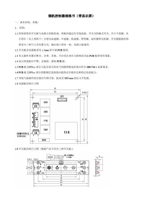
烟机控制器规格书(带显示屏)一.基本结构、参数:1.结构:1.1控制系统有开关板与电源主控板组成,两板间通过信号线连接,开关为轻触式开关,共六个按键,从左到右(从上到到下)分别为高速键、中速键、低速键、照明键、延时键和关机键。
开关板根据结构要求分三种尺寸及布置方式,输出接口排布一致,电源主板通用。
1.2开关板及电源板采用1.5mm厚半玻PCB板材。
1.3各元器件布置应整齐、合理、美观,不应受自身应力影响而引起PCB板材变形现象。
1.4显示屏装配应平整、无倾斜,紧贴PCB板。
1.5 PCB板220Va.c部分与低压部分的电气间隙和爬电距离应符合GB4706.1标准要求。
1.6 PCB板220Va.c部分的敷铜层连接线应能保证负载有足够的过电流能力。
1.7导线与接插件的压接应牢固可靠,能承受30N/min的拉力不松脱。
1.8电源板结构尺寸图1.9开关板结构尺寸图(根据产品不同分三种开关板):1.10开关板与电源板连接线1. 11上述电源板的元器件布置仅供参考,具体可按设计需要调整,但尺寸应符合要求。
2.基本参数:2.1额定输入工作电压:220V a.c;可工作电压范围:0.8倍~1.1倍额定工作电压。
2.2风机额定工作电压:220V a.c;驱动器件7A继电器。
2.3照明额定工作电压:220V a.c;驱动器件3A继电器。
2.4高速、中速、低速档继电器切换延时时间:0.1s。
2.5按键响应有效时间:0.15s≤T≤0.3s;按键为下压时有效。
2.6按键提示声时间: ≤1.5s。
2.7延时关机时间:3min±3s。
2.8变压器空载电流≤25mA;带载运行温升≤35K。
二.按键功能及显示要求:1、按键说明:1.1“电源”键:按键进入启动状态,5s内如无键操作则自动退出到待机状态。
1.2“高速”键:开启和关闭风机的高速档,为循环开/关方式,并与“中速”及“低速”键互锁。
“延时”键:工作状态下按键1次1.3“中速”键:开启和关闭风机的中速档,为循环开/关方式,并与“高速”及“低速”键互锁。
万家乐吸油烟机使用说明书
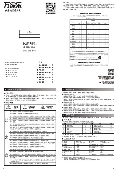
尊敬的用户:由衷地感谢您选购万家乐牌吸油烟机。
在您安装使用本产品前,请仔细阅读随机附带的使用说明书以及各个文件。
阅后,请与购机发票一起妥善保管,以备日后查阅。
本产品执行国家标准:GB4706.28-2008GB29539-2013GB/T 17713-2011GB 4706.1-2005吸油烟机使用说明书使用产品前请仔细阅读本使用说明书, 并妥善保管为了避免对使用人员及其他人员造成危害及财产损害,请仔细阅读以下有关安全的重要事项,敬请严格遵守,并在充分理解内容的基础上正确使用。
使用前,请您仔细阅读本说明书并严格按照说明书规定使用,如因对本产品使用不当而造成的人身伤害、财产损失,本公司不承担任何法律责任。
安全须知本说明书中内容及参数与实物有差异,或吸油烟机设计上因改动与说明书中有差异,不另行说明,以实物为准。
重要信息吸油烟机长期不使用时,请将电源插头从插座中拔出来。
新吸油烟机的安装如发现附件与说明书不符,请与当地经销商或服务中心联系。
请以环保的态度处置可回收的包装材料,以保持一个良好的环境。
请勿让儿童玩耍塑料薄膜和包装箱,这可能会产生窒息事故,所以请让包装材料远离儿童,包装材料不是玩具。
旧吸油烟机的处理当旧的吸油烟机无法使用时,请剪断电源线使其无法通电使用。
旧的吸油烟机中包含可再利用的材料,请协助处理或回收利用,从而对环境保护做出贡献。
使用新吸油烟机之前如发现吸油烟机有明显的损坏,请勿安装使用,请立即与当地经销商或服务中心联系。
为确保您能正确地、更安全地使用本吸油烟机,在使用之前请您仔细阅读您所购买的吸油烟机的使用说明书,并严格遵守使用说明书中的注意事项。
产品中有害物质的名称及含量根据中华人民共和国《电器电子产品有害物质限制使用管理办法》,列出了本产品中可能包含的有害物质的名称和含量。
为了更好地关爱及保护地球,当用户不再需要此产品或产品寿命终止时,请遵守国家电器电子产品相关法律法规,将其交给当地具有国家认可的回收处理资质的厂商进行回收处理。
【最新】油烟机电机接线图

【最新】油烟机电机接线图抽油烟机其实现在很多家庭都在使用抽油烟机这样的厨卫电器产品,当然有了它能给我们的厨房带来一定的新鲜空气,而且还可以帮助排除我们厨房的废气哦,可以说是一举两得。
在安装的时候一定要注意电机的接线问题,下面就给大家介绍一下抽油烟机电机接线图及分析。
抽油烟机电机接线图及分析要保证接线准确无误,最好用万用表R_10档来测试电机绕组的直流电阻,根据绕组出线的直流电阻值进行判断接线。
首先确定启动绕组,可以用万用表测量,与黑色电阻最大的那条就是启动绕组(电容线),与黑色电阻最小的为高速,阻值居中的为低速,红-1速(高)蓝-2速(低)黄-电容黑-电容-零线就是黑色,黄色接电容,黑色再接电源其中一条线,电源另外一条线接双速开关上分成二个速度。
一般的电机有4根引出线。
1,用万用表R_10档找出其中电阻值最大的两根线,在标准产品中,此二线一般以蓝、黑为代表,对于引出线之间直流电阻值要进行比较,辨别出R 值最大的两根。
并把电容器的两个端子连接到这两根线上。
2、把连接电容器的这两根线的其中一根(蓝线,或黑线)接到电源的零线(公共端子)上。
3、把剩余的两根导线分别且任意地接到油烟机的“快慢”档上,这两根线是电源的火线,快慢档就是用开关来控制电机的火线端子,(试机时如果快慢相反,对调快慢引出线在开关上的位置就可)。
4,接好后可以通电试验,此时可能电机会反转,出现此情况把接电容器的两根电机引出线对调就行了,一切正常后就可以进一步处理引线的绝缘和布线。
5.电源进线L为红色线,N为黑色线,两只照明灯的黑色线通到控制板,照明灯的另一端是蓝色线铰接在一起,从控制板出来3根线,分别是红色线、黑色线、白色线,这3根线中必定有1根是照明灯控制线,于是把照明灯的两根蓝色线和控制板出来的白色线连接,插上电源插头,控制板显示屏亮,照明灯不亮,按下控制板照明灯按钮,照明灯点亮,说明照明灯接线正确。
总结:以上就是对抽油烟机电机接线图以及分析的介绍,不知道大家都了解了多少呢,是不是心里已经有了一定的数,如果以后遇到这类问题是不是可以自己动手试一试呢?希望能对大家有一定的帮助。
除油烟机 安装及说明书
除 油 煙 機高排煙力以讓您使用得更舒適、更清靜。
安裝及使用前,請先詳細閱讀此說明書。
感謝您對本產品的惠顧,本系列產品始終秉持親愛的顧客:最佳的品質及完善的服務外,並追求低噪音及※本說明書內示意圖樣僅供參考,實際以實體為主。
安裝完畢後,請務必將此說明書交給顧客妥善保管。
若對本產品有任何使用上的疑問或需服務的地方請洽各區代理商服務站。
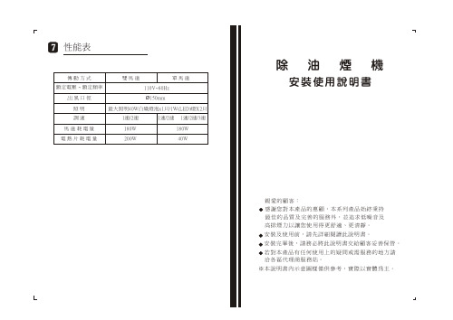
安裝使用說明書性能表傳 動 方 式 雙 馬 達 單 馬 達額定電壓出 風 口 徑 Ø150mm照 明 最大照明40W白熾燈泡x1只/1W(LED)燈X2只~ 額定頻率110V~60Hz調 速 1速/2速 1速/2速 1速/2速/3速 馬 達 耗 電 量 180W 180W 電 熱 片 耗 電 量 200W 40W二. 按裝施工說明.............P3四. 使用注意事項.............P5一. 按 裝 原 則...............P2 三. 使用方法.................P4七. 性能表..................P7五. 保 養.................P5六. 異常狀況之處理...........P6異常狀況之處理使用中發現異常狀況時,請將電源插頭拔掉,並就近洽經銷商或服務站或具專業資格人員至府上維修。
處理異常狀況時請將開關電源關掉。
異常狀況原 因 及 處 置 方 法電源線損壞請就近洽經銷商或服務站或具有專業資格人員至府上維修。
電源線規格:300V 0.75mm2*3c。
插頭規格:125V 7A 兩扁一圓插頭。
馬達不轉A. 查看開關或插頭接觸是否正常。
B. 查看燈泡是否會亮以確定電源是否正常。
C. 拆下保護網,用手轉動風葉,如轉不動則查看風葉是否 卡住。
若是,則請更換整組馬達。
D.如風葉用手輕動皆能運轉自如,則是電容器的問題:1.先查看電容器與馬達接線是否脫落。
2.若接線正常,就是電容器損壞,必須更換電容器。
A70 半嵌入式抽油烟机 中文操作手册说明书
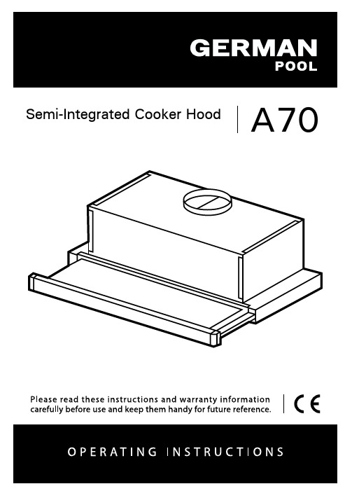
A70 Semi-Integrated Cooker HoodINDEXRECOMMENDATIONS AND SUGGESTIONS (3)CHARACTERISTICS (6)INSTALLATION (7)USE (9)MAINTENANCE (10)RECOMMENDATIONS AND SUGGESTIONSThe Instructions for Use apply to several versions of this appliance.Accordingly, you may find descriptions of individual features that do not apply to your specific appliance.INSTALLATION•The manufacturer will not be held liable for any damages resulting from incorrect or improper installation.• The minimum safety distance between the cooker topand the extractor hood is 650 mm (some models canbe installed at a lower height, please refer to theparagraphs on working dimensions and installation).• Check that the mains voltage corresponds to thatindicated on the rating plate fixed to the inside of thehood.• For Class I appliances, check that the domesticpower supply guarantees adequate earthing.Connect the extractor to the exhaust flue through a pipe of minimum diameter Ø 125 /5” , Ø 152/6” . The route of the flue must be as short as possible. • Do not connect the extractor hood to exhaust ducts carrying combustion fumes (boilers, fireplaces, etc.).• If the extractor is used in conjunction with non-electrical appliances (e.g. gas burningappliances), a sufficient degree of aeration mustbe guaranteed in the room in order to prevent thebackflow of exhaust gas. The kitchen must havean opening communicating directly with the openair in order to guarantee the entry of clean air.When the cooker hood is used in conjunction withappliances supplied with energy other than electric, the negative pressure in the room must not exceed 0,04 mbar to prevent fumes being drawn back into the room by the cooker hood.• In the event of damage to the power cable, it must be replaced by the manufacturer or by the technical service department, in order to prevent any risks.• If the instructions for installation for the gas hob specify a greater distance specified above, this has to be taken into account. Regulations concerning the discharge of air have to be fulfilled.• Use only screws and small parts in support of the hood.Warning: Failure to install the screws or fixing device in accordance with these instructions may result in electrical hazards.• Connect the hood to the mains through a two-pole switch having a contact gap of at least 3 mm.USE•The extractor hood has been designed exclusively for domestic use to eliminate kitchen smells.• Never use the hood for purposes other than for which it has been designed. • Never leave high naked flames under the hood when it is in operation. • Adjust the flame intensity to direct it onto the bottom of the pan only, making sure that it does not engulf the sides.• Deep fat fryers must be continuously monitoredduring use: overheated oil can burst into flames.• Do not flambè under the range hood; risk of fire.• This appliance can be used by children aged from8 years and above and persons with reducedphysical, sensory or mental capabilities or lack ofexperience and knowledge if they have been given supervision or instruction concerning use of the appliance in a safe way and understand the hazards involved. Children shall not play with the appliance. Cleaning and user maintenance shall not be made by children without supervision.• “CAUTION: Accessible parts may become hot when used with cooking appliances.”MAINTENANCE•Switch off or unplug the appliance from the mains supply before carrying out any maintenance work.• Clean and/or replace the Filters after the specified time period (Fire hazard). • The Grease filters must be cleaned every 2 months of operation, or more frequently for particularly heavy usage, and can be washed in a dishwasher. • The Activated charcoal filter is not washable and cannot be regenerated, and must be replaced approximately every 4 months of operation, or more frequently for particularly heavy usage.• Clean the hood using a damp cloth and a neutral liquid detergent.The symbol on the product or on its packaging indicates that this product may not be treated as household waste. Instead it shall be handed over to the applicable collection point for the recycling of electrical and electronic equipment. By ensuring this product is disposed of correctly, you will help prevent potential negative consequences for the environment and human health, which could otherwise be caused by inappropriate waste handling of this product. For more detailed information about recycling of this product, please contact your local city office, your household waste disposal service or the shop where you purchased the product.CHARACTERISTICSDimensionsComponentsRef. Q.ty Product Components1 1 Hood Body, complete with: Controls, Light, Blower,Filters8 1 Directional Air Outlet grille9 1 Reducer Flange Ø 125 / Ø 15220 1 Closing elementRef. Q.ty Installation Components12a 4 Screws 4,2 x 44,412b 2 Screws 4,2 x 12,712e 2 Screws 2,9 x 9,5Q.ty Documentation1Instruction ManualINSTALLATIONDrilling the Support surface and Fitting the HoodSCREW FITTING• The hood support surface must be 135 mm above the bottom surface of the wall units.• Drill the support with a ø 4,5 mm drill bit, using the drilling template provided.• Cut a hole ø 150 mm in size on the support surface, using the drilling template provided.• Fix using the 4 screws 12a (4,2 x 44,4) provided.SNAP-ON FITTING• The hood can be installed either directly on the bottom surface of the wall units using snap-on side supports.• Cut a fitted opening in the bottom surface of the wall unit, as shown.• Insert the hood until the side supports snap into place.• Lock in position by tightening the screws Vf from underneath the hood.Hood Type 45 50 55 60 70 80 90 L1360 410 460 510 610 710 810CLOSING ELEMENT• The space between the edge of the hood and the rear wall can be closed by applying the element 20provided, using the screws 12b.ConnectionsDUCTED VERSION AIR EXHAUST SYSTEM When installing the ducted version, connect the hood toor ø125 mm, the choice of which is left to the installer. • To install a ø 125 mm air exhaust connection, insert the reducer flange 9 on the hood body outlet.• Fix the pipe in position using sufficient pipe clamps (not supplied).• Remove possible charcoal filters.RECIRCULATION VERSION AIR OUTLET• Cut a hole ø 125 mm in any shelf that may be posi-tioned over the hood.• Insert the reducer flange 9 on the hood body outlet. • Connect the flange to the outlet on the shelf over the hood by using a flexible or rigid pipe ø125 mm. • Fix the pipe in position using sufficient pipe clamps (not supplied).• Fix the air outlet grid 8 on the recirculation air outlet by using the 2 screws 12e (2,9 x 9,5) provided. • Ensure that the activated charcoal filters have beeninserted.zELECTRICAL CONNECTION• Connect the hood to the mains through a two-pole switch having a contact gap of at least 3 mm.• When opening the sliding carriage for the first time after installing the hood, pull it out briskly until it clicks.USEControl panelL Light Switches the lighting systemon and off.M Motor Switches the extractor motoron and off.V Speed Sets the operating speed of theextractor:1. Low speed, used for a con-tinuous and silent airchange in the presence oflight cooking vapour.2. Medium speed, suitable formost operating conditionsgiven the optimum treatedair flow/noise level ratio.3. Maximum speed, used foreliminating the highestcooking vapour emission,including long periods. LM Motor Switches the extractor motoron and off.V Speed Sets the operating speed of theextractor:1. Low speed, used for a con-tinuous and silent airchange in the presence oflight cooking vapour.2. Medium speed, suitable formost operating conditionsgiven the optimum treatedair flow/noise level ratio.MAINTENANCEter efficiency).• When refitting the filters, make sure that the handle is visible on the outside.• Close the sliding suction panel.MAINTENANCECharcoal filter (Recycling version)REPLACING CHARCOAL FILTERSWarning: Turn the lights off and wait until the lamps cool down before you change the odour filter.• These filters are not washable and cannot be regenerated, and must be replaced approximately every four months or more frequently by particularly heavy use.• Pull out the sliding suction panel.• Remove the grease filters.• Remove the saturated carbon filter by releasing the fixing hooks• Fit the new filter by hooking it into its seating.• Replace the grease filters.•Close the sliding suction panel.LightingLIGHT REPLACEMENT28W-40W light.• Remove the metal grease filters.• Unscrew the bulbs and replace them with new ones having the same characteristics.•Replace the metal grease filters.請即進行保用登記﹗有關保用條款細則,請看本說明書最後一頁。
BOSCH 抽油烟机 产品说明书
Serie | 6, Built-in microwave oven with hot air, 60 x 45 cm, Stainless steelCMA585MS0B Included accessories 1 x grid high 1 x grid flat 1 x TurntableOptional accessoriesHEZ915003 : Glass roasting dish, 5,4 LThe built-in compact microwave defrosts,heats and cooks helping you prepare food in the kitchen.Pop-out controls: for an easy to clean front.Technical DataType of micro-wave oven : MW-Combi Type of control :Electronic Color / Material Front : Stainless steel Dimensions :454 x 594 x 570Cavity dimensions (mm) :220 x 420 x 420Length electrical supply cord (cm) : 180Net weight (kg) : 35.108Gross weight (kg) : 39.1EAN code :4242005036639Maximum micro-wave power (W) : 900Connection Rating (W) : 3350Current (A) : 16Voltage (V) :220-240Frequency (Hz) : 50Plug type :fixed connection'!2E 20A F -a d g d j !1/3Serie | 6, Built-in microwave oven with hot air, 60 x 45 cm, Stainless steel CMA585MS0BThe built-in compact microwave defrosts,heats and cooks helping you prepare food in the kitchen.Design-LCD Display, White -Electronic clock timer-Rotary dial, Retractable control dials, Touch controls, round,Start button-Straight bar handle -Touch key operation -Drop down door-stainless steel cavity interior -36 cm Metal turntableFeatures-Control panel lockAutomatic safety switch offDoor contact switch-AutoPilot, 15-LED light-Integral cooling fanProgrammes/functions-Built-in Microwave with hot air function with the heatingfunctions: Microwave, Hot Air Cooking, Hotair grilling, full width variable grill, pizza function-Microwave may be used separately or in combination-Grill and microwave power levels 90 W, 180 W, 360 W, 600 Wcombinable-900 W maximum microwave power and the following options:180 W, 360 W, 600 W, 90 W, 900 W-1.75 KW grill function-4 defrost and 3 cooking programmes in microwave function, 8programmes for combination function-Fast pre-heating functionAccessories-1 x Turntable, 1 x grid high, 1 x grid flatPerformance/technical information-Temperature range 40 °C - 230 °C -Cavity volume: 44 l -180 cm Cable length-Total connected load electric: 3.35 KW -Nominal voltage: 220 - 240 V -Appliance dimension (hxwxd): 454 mm x 594 mm x 570 mm-Niche dimension (hxwxd): 450 mm - 452 mm x 560 mm - 568mm x 550 mm -Please refer to the dimensions provided in the installationmanual2/3Serie | 6, Built-in microwave oven with hotair, 60 x 45 cm, Stainless steelCMA585MS0B3/3。
吸油烟机的接线图
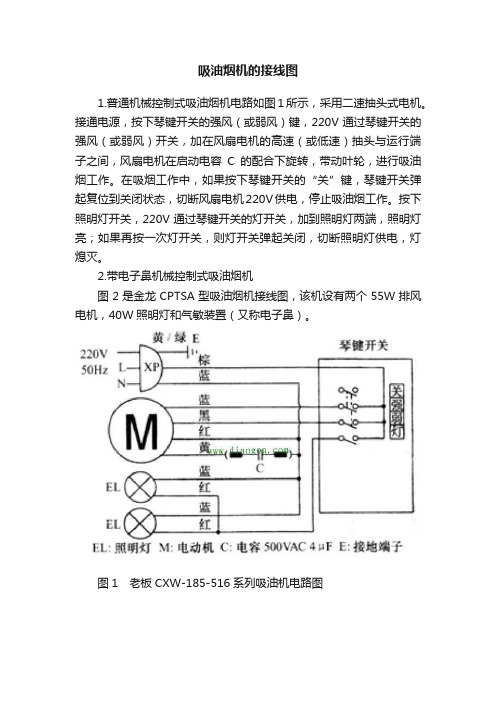
吸油烟机的接线图1.普通机械控制式吸油烟机电路如图1所示,采用二速抽头式电机。
接通电源,按下琴键开关的强风(或弱风)键,220V通过琴键开关的强风(或弱风)开关,加在风扇电机的高速(或低速)抽头与运行端子之间,风扇电机在启动电容C的配合下旋转,带动叶轮,进行吸油烟工作。
在吸烟工作中,如果按下琴键开关的“关”键,琴键开关弹起复位到关闭状态,切断风扇电机220V供电,停止吸油烟工作。
按下照明灯开关,220V通过琴键开关的灯开关,加到照明灯两端,照明灯亮;如果再按一次灯开关,则灯开关弹起关闭,切断照明灯供电,灯熄灭。
2.带电子鼻机械控制式吸油烟机图2是金龙CPTSA型吸油烟机接线图,该机设有两个55W排风电机,40W照明灯和气敏装置(又称电子鼻)。
图1 老板CXW-185-516系列吸油机电路图图2 金龙CPTSA型吸油烟机接线图(l)照明灯控制在开关K4和停止开关闭合时,220V电源电压就可加到照明两端,照明灯亮。
再按开关K4,则该开关复位到断开状态,切断照明灯220V供电,照明灯熄灭。
(2)左/右风扇手动控制按下左/右风扇开关K2、K3,220V电源电压通过这两个开关、气敏装置上的继电器J常闭触点、停止开关K5常闭触点,加到左/右风扇电机Ml、M2两端,在1.2VF的启动电容的配合下,左/右风扇电机运转进行吸油烟工作。
在吸油烟工作期间,如果按下开关K2(或K3时),则该开关弹起,复位到断开状态,切断风扇电机M1(或M2)的220V供电,风扇电机M1(或M2)停止运转。
在吸油烟工作期间,如果按下停止开关K5,则切220V供电,风扇电机、照明灯、气敏装置等220V供电,整机停止工作。
3.气敏自动控制气敏装置内部电路如图3所示,继电器J触点为常闭;QM是气敏管,接触可燃气体时电阻下降(气体浓度越高阻值越小);运算器IC2(Al、A2、A3、A4)负责气敏检测及控制,IC3(KD-9561)负责气敏报警控制。
方太油烟机系列产品使用安装说明书

操作
警告 1. 防过猛过重操作按键; 2. 防灶具空烧; 3. 防通电拆卸和违嘱拆卸; 4. 防油杯油满外溢; 5. 防非专业人员拆检; 6. 禁止炉火直接烘烤油烟机。
使用方法 操Βιβλιοθήκη 界面描述产品信息型号
EMG9030
净重
76 lbs(34.5 Kg)
油网及蝶翼板中的油脂沉淀物可能着火,绝不 在此产品附近使用明火。请不要在使用固体燃 料(比如木头或煤)的加热设备附近安装此产 品。禁止有飘飞的火花。 请避免在烟机下方使用会产生火焰的食品。 为降低灶台油火风险: 1. 绝不使灶台表面的器具在无人看管下高档位
运行。溢锅造成冒烟和可能起火的油脂外溢, 请在低档或中档设置下缓慢加热油脂。 2. 烹饪时请总是开启烟机。 3. 请清洁油烟机,叶轮、滤网上或在排烟管道 里不应积油。 4. 请使用合适尺寸的锅具。请总是使用与灶台 表面的器具尺寸吻合的炊具。 为降低灶烤一体机上方油火对人身伤害的危 险,请遵守以下说明: 1. 用合身的锅盖、烤板或金属托盘扑灭火焰, 然后关闭灶具。注意谨防烫伤。如果火焰未 立即熄灭,请疏散并报火警。 2. 油锅着火时,请立即关闭油烟机 ( 油烟机的 运行会助燃火势 )。立即采用有效的灭火措 施,如用金属封盖盖住明火、关闭燃气总阀、 使易燃物远离明火等。 3. 绝不拿起着火的锅具,您可能被烫伤。 4. 请勿用水,包括湿抹布或毛巾灭火,这样会 导致猛烈的蒸汽喷发。 仅在以下条件使用灭火器: 1. 当您上过基础的灭火器课程,并且已经知 道如何操作; 2. 当火较小并且控制在火源处; 3. 当您已打火警电话; 4. 当您背向出口时可救火。 人身伤害危险 此产品不适用于(包括儿童在内)身体、感知 或精神能力减弱或缺乏经验或知识的人群,除 非在对其安全负责的人监督或指导如何安全使 用此产品的情况下。孩童应受监管,确保其不 玩弄此产品。 油烟机可能有非常锋利的边,在进行安装、清 洁或修理时,谨防被油烟机内金属板快口等划 伤和擦伤。应佩戴合格的防护手套。 操作中可触及部分会变得很烫。绝不触摸变烫 的部分。保持儿童在安全距离以外。
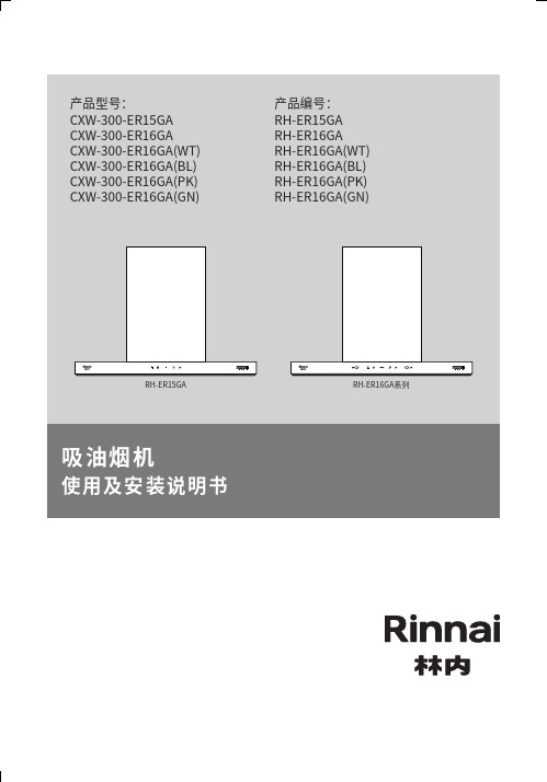
林内RH-ER15GA RH-ER16GA系列吸油烟机使用及安装说明书
1
2
注:空气性能特性曲线及阻力曲线不作为明示参数的一致性评价依据。
静压(P a )
标引序号说明: 1 — 空气性能特性曲线 2 — 排烟阻力曲线
上海林内有限公司
Shanghai Rinnai Co., Ltd.
公司地址:上海市奉贤区团青公路4500号 电话:(021)67583500 传真:(021)67583555 邮编:201411上海林内有限公司售后服务中心地址:上海市奉贤区团青公路4500号 传真:(021)67583555
邮编:201411上海林内有限公司展示厅地址:上海市南京西路499号 电话:(021)63590262
邮编:200003全国服务热线:4006990606
SX021-608
敬告:
由于产品的改进,本说明书中的某些内容,插图可能与产品不完全一致,恕不另行通知,产品规格以器具铭牌为准,请谅解。
扫描此二维码获取林内官网扫描此二维码获取林内官方微信服务号扫描此二维码获取售后网点。
抽油烟机使用说明书 - Power Series PW2300HAS、PW2336HAS
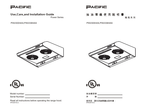
抽油煙機使用說明書極 風 系 列抽油機型號:序 號:Use,Care,and lnstallation GuidePower SeriesPW2300HAS,PW2336HASPW2300HAS,PW2336HASModel number:Serial Number:IMPORTANT SAFETY NOTICEREAD AND SAVE THESE INSTRUCTIONS a) Use this unit only in the manner intended by the manufacturer, if you have questions, contact the manufacturer.b) Before servicing or cleaning unit, switch power off at service panel and lock the service disconnecting means to prevent power from being switched on accidentally. When the service disconnecting means cannot be locked, securely fasten a prominent warning device, such as a tag, to the service panel.a) Never leave surface units unattended at high settings. Boil overs cause smoking and greasy spillovers that may ignite. Heat oils slowly on low or medium settings.b) Always turn hood ON when cooking at high heat or when flaming food.(i.e.Cherries Jubilee, Peppercom Beef Flambe’).c) Clean ventilating fans frequently. Grease should not be allowed to accumulate on fan or filter.d) Use proper pan size. Always use cookware appropriate for the size of the surface element.e) Keep fan, fillters and grease laden surfaces clean.f ) Use high setting on hood only when necessary. g) Don’t leave hood unattended when cooking.h) Always use cookware and utensils appropriate for the type of and amount of food being prepared. a) SMOTHER FLAMES with a close-fitting lid, cookie sheet, or metal tray, then turn off the burner. BE CAREFUL TO PREVENT BURNS. If the flames do not go out immediately, EVACUATE AND CALL THE FIRE DEPARTMENT.b) NEVER PICK UP A FLAMING PAN – You may be burned.c) DO NOT USE WATER, including wet dishcloths or towels – a violent steam explosion will result.d) Use an extinguisher ONLY if:1) You know you have a Class ABC extinguisher, and you already know how to operate it. 2) The fire is small and contained in the area where it started. 3) The fire department is being called.4) You can fight the fire with your back to an exit WARNINGWARNINGTO REDUCE THE RISK OF FIRE, ELECTRIC SHOCK, OR INJURY TO PERSONS, OBSERVE THE FOLLOWING:WARNING -TO REDUCE THE RISK OF A RANGE TOP GREASE FIRE:WARNING -TO REDUCE THE RISK OF INJURY TO PERSONS IN THE EVENT OF A RANGE TOP FIRE, OBSERVE THE FOLLOWING:WARNING -TO REDUCE THE RISK OF FIRE, ELECTRIC SHOCK OR INJURY TO PERSONS, CAUTIONFor General Ventilating Use Only. Do Not Use To Exhaust Hazardous Or Explosive Materials And Vapors. TO REDUCE THE RISK OF FIRE OR ELECTRIC SHOCK, DO NOT USE THIS FAN WITH ANY SOLID-STATE CONTROL DEVICE.IMPORTANT SAFETY NOTICEa) Installation work and electrical wiring must be done by qualified person(s) in accordance with all applicable codes and standards. Including fire-rated construction.b) Sufficient air is needed for power combustion and exhausting of gases through the flue (chimney) of fuel burning equipment to prevent back-drafting. Follow the heating equipment manufacturer’s guideline and safety standards such as those published by the National Fire Protection Association (NFPA) and the American Society for Heating, Refrigeration and Air Conditioning Engineers (ASHRAE) and the local code authorities.c) When cutting or drilling into wall or ceiling, do not damage electrical wiring and other hidden utilities.d) Ducted fans must always vent to the outdoors.e) NEVER place a switch where it can be reached from a tub or shower.f ) Make sure the power is off before installing, wiring or maintenancing.WARNINGTO REDUCE THE RISK OF FIRE, USE ONLY METAL DUCTWORK. ELECTRICAL REQUIREMENTSImportant: Observe all governing codes and ordinances. OPERATIONAlways leave safety grilles and filters in place. Without these components, operating blowers could catch onto hair, fingers and loose clothing.The manufacturer declines all responsibility in the event of failure to observe the instructions given here for installation, maintenance and suitable use of the product. The manufacturer further declines all responsibility for injury due to negligence and the warranty of the unit automatically expires due to improper maintenance. CAUTIONTo reduce risk of fire and to properly exhaust air outside - Do not vent exhaust air into spaces within walls, ceilings, attics, crawl spaces or garages.It is the customer’s responsibility:- To contact a qualified electrical installer.- To assure that the electrical installation is adequate and in conformance with National Electrical Code, ANSI/NFPA 70 latest edition* or CSA standards C22.1-94, Canadian Electrical Code, Part 1 and C22.2 No.0-M91 - latest edition** and all local codes and ordinances.If codes permit and a separate ground wire is used, it is recommended that a qualified electrician determine that the ground path is adequate.*National Fire Protection Association Batterymarch Park, Quincy, Massachusetts 02269** CSA International 8501 East Pleasant Valley Road, Cleveland, Ohio 44131-5575This appliance requires a 120V 60Hz electrical supply and connected to an individual properly grounded branch circuit protected by a 15 or 20 ampere circuit breaker or time delay fuse. Wiring must be 2 wire with ground. Please also refer to Electrical Diagram on product.Do not have a fuse in the neutral or ground circuit.Check with a qualified electrician if you are not sure the range hood is properly grounded.Do not ground to a gas pipe.目錄一.功能簡介/性能規格表………………………....1二.配件說明………………………………………. 2三.安裝原則………………………………………. 3四.安裝步驟………………………………………. 4五.按鍵說明 ….........................................… 5 .......................................5 六.移除燈泡.............................................. 6七.機身表面保養和清潔 ................................ 7八.注意事項...............................................8九.排除故障. (9)Table of ContentI. PRODUCT FEATURES/PERFORMANCE SPECIFICATION CHART..1II. PARTS INSTRUCTIONS ........................................................2III. INSTALLATION GUIDELINES ...........................................3IV. INSTALLATION PROCEDUR ES . (4)V. OPERATING INSTRUCTIONS VI. REPLACING LIGHT BULB ................................................6VII. SURFACE MAINTENANCE ..............................................7VIII. CAUTIONS ....................................................................8IX. TROUBLESHOOTING (9)I. PRODUCT FEATURES/PERFORMANCE SPECIFICATION CHARTA. Product FeaturesModel:PW2300HAS,PW2336HAS 1. 6-speed options.2. Light has varying degrees of brightness: Bright, Dim and Off.3. Delay-off function.4. Display Window: indicates speed levels and delay off, heater.B. Performance Specification Chart PW2336HAS PW2300HAS 2.0A/214W Net Weight(LBS)ModelsMeasurement (inch)Maximum Voltage Exhaust Pipe Diamet AL foil heater powerer LightMaximum consumption powerRound 7 inches, Rectangle 3-1/4"x10 inches LED Light strip 8Wx1120V – 60Hz29-3/4"X24-13/16"X7-7/8"35-11/16"X24-13/16"X7-7/8"37.9 LBS34.1 LBS一.功能簡介/性能規格表1. 6速風速選擇。
抽油烟机说明书

抽油烟机说明书尊敬的用户:感谢您选择使用我们的抽油烟机,并给予我们的产品信任。
为了确保您能充分了解和正确使用我们的抽油烟机,我们编写了以下说明书,希望能为您提供清晰的使用指南。
一、产品概述我们的抽油烟机是一种家用厨房电器,主要用于吸附和排除烹饪过程中产生的油烟、异味和热气等有害物质,确保厨房空气的清洁与流通。
我们的产品结构合理、设计前卫,外观精致美观,操作简便,具有以下特点:1. 强劲的排风功能:通过高效电机及优质风叶的配合,实现了快速、高效的排风效果,有效清除油烟和异味,保持厨房空气清新。
2. 多档调速:内置多档风速调节功能,您可以根据不同的烹饪需求选择适当风速,保证烹饪时的灵活性和舒适性。
3. 超静音设计:通过科学的降噪技术和优质材料的使用,使得我们的抽油烟机在工作时噪音极低,不会对您的生活和休息造成干扰。
4. 易于清洁:我们的抽油烟机设计合理,可拆卸清洗,方便快捷,确保产品始终保持洁净卫生。
二、安装说明1. 安全须知:在安装我们的抽油烟机之前,请务必仔细阅读并理解以下安全须知:1.1 请确保安装环境通风良好,不要堵塞抽油烟机的进出风口。
1.2 请确保电气安装符合国家/地区的相关规范,避免因错误电气连接引起安全隐患。
1.3 请在使用过程中,保持抽油烟机与可燃物体保持一定的距离,避免因接触火源引起事故。
1.4 请勿将抽油烟机安装于高温、潮湿或易燃的环境中,避免影响产品安全性能。
2. 安装步骤:我们提供了详细的安装图解供您参考,在安装之前,您可以阅读以下步骤:2.1 确定安装位置:请根据您的厨房布局和操作需求,选择适当的安装位置,确保与烹饪设备之间有足够的间隔。
2.2 安装支架:将抽油烟机支架固定于安装位置,确保支架水平牢固。
2.3 安装油烟机:将抽油烟机的连接口与支架连接好,确保稳定。
2.4 连接电源:根据产品说明书上的电气连接图,正确接入电源线,确保安全可靠。
2.5 安装检查:在完成以上步骤后,请检查安装是否牢固可靠,所有电气接线是否正确无误。
抽油烟机产品说明书.

抽油烟机说明书
一、产品特色
✧本产品材质采用
✧医用级不锈钢
✧防腐耐摔
✧侧吸式
✧不容易碰
头,外观
时尚
✧采用现代
工业自动
控制技
术、互联
网技术与多媒体技术的完美组合,为
现代智能厨房提供了样板
二、产品优势◆安装在厨
房健康节能◆吸油烟机炉灶上方
◆能将炉灶燃烧的废物和烹饪过程中产生的对人体有害的油烟迅速抽走
◆排出室外
◆减少污染,净化空气,并有防毒、防爆的安全
三、装配示意图
四、售后服务
全国联保,2年保修,7天包退,30天包换。
服务热线700820。
老板吸油烟机使用说明书

CXW-CXW-使用产品前请仔细阅读本使用说明书,并妥善保管本产品执行标准 GB/T 17713 GB 4706.1 GB 4706.28 GB 19606 GB 29539老板厨房电器 为世界构建更多幸福的家目 录1.安全注意事项 (1)2.重要信息 (3)3.产品简介 (4)4.装箱单 (4)5.安装说明 (5)6.使用说明 (8)7.维护与保养 (10)8.部件拆卸 (10)9.线路图 (12)10.一般故障的排除 (13)11.客户服务 (14)12.全国电码电话防伪查询使用说明 (15)13.产品包修卡 (16)●吸油烟机的安装及电路设置必须由有经验的专业人员进行,只有经过专业培训的,并具有安装资质的人员,才能对吸油烟机进行安装,非专业人员请勿安装、拆卸及维修吸油烟机。
●安装前请勿接通吸油烟机电源,以免触电。
●如果您的厨房正处于装修状态,请勿将吸油烟机暴露在外,因为建筑材料、灰尘、油漆、涂料以及它们所挥发的气体,会使吸油烟机表面产生腐蚀和失去光泽。
因此建议您在装修完毕后再安装吸油烟机。
●如果在安装吸油烟机前,需要移动燃气灶,则在移动燃气灶前,请先关闭燃气叫阀门。
●请勿将吸油烟机安装在木质等易燃物的墙面上,安装吸油烟机的墙面应为有足够强度的不可燃物,且表面平直。
●吸油烟机可能有非常锋利的边,在移动吸油烟机进行安装、清洁或修理时,请佩戴防护手套。
●在墙壁或天花板等上面钻孔时,应避开墙内埋设的电线及其它隐藏设备,以免引起触电及火灾。
●吸油烟机不要装得太高,也不要受外界气流干扰,以免降低吸烟效果。
●制作橱柜时,请给机体留下装取空间,以利维护保养与检修。
●装机时,请使机体保持水平。
●请使用单相带接地插座,并良好接地(自来水管接地不可靠,煤气管道接地有引发火灾与爆炸的危险)。
●为保证安全和安装顺利,请使用随机附件进行安装,否则吸油烟机可能会有掉下来的危险。
●如电源软线损坏,为了避免危险,必须由制造商、其维修部或类似部门的专业人员进更换。
Miele 抽油烟机 DA 428-4 使用和说明书

抽油烟机DA 428-4DA 428-4 EXT DA 429-4DA 429-4 EXT为了避免发生事故或损坏本机器,请您务必在安装和首次使用之前仔细阅读本说明书。
v M.-Nr. 06 812 820目录环境保护 (3)注意事项和安全说明 (4)工作模式 (9)结构示意图 (10)操作 (12)打开排气扇 (12)选择风力 (12)加强设置 (12)延续运行选项 (13)关闭排气扇 (13)打开炉具照明灯 (14)调节炉具照明灯 (14)关闭炉具照明灯 (14)滤油网使用时间计数器 (14)清洁与保养 (18)外壳 (18)滤油网 (19)安装和更换活性炭过滤网 (21)更换卤素灯泡 (22)售后服务 (23)抽油烟机尺寸 (24)安全距离(S) (25)安装 (26)组装配件 (26)安装说明 (28)保护膜 (28)拆除 (28)排气管道的连接 (29)冷凝槽 (30)减噪器 (30)电源连接 (31)用DSM 400控制模块进行操作 (32)连接到窗户接触开关 (32)连接其他设备的可能性 (32)连接到照明开关 (33)技术参数 (34)2环境保护包装材料的处理用于运输和保护的包装材料符合环保规范,通常可以回收再利用。
切勿将包装材料,比如包装薄膜、聚苯乙烯和塑料包装放在婴儿或儿童可以触及的地方。
以防止因误用而导致儿童窒息!请您尽可能迅速地处理或者循环利用所有的包装材料。
处理旧的机器电器和电子设备中往往包含某些特殊材料,这些材料如果处理不当或随意丢弃,可能会对人类健康和环境造成潜在的危害。
然而,对您的电器设备而言,它们是使其正常运作不可或缺的部分。
因此,请不要将旧的设备与生活垃圾丢弃在一起。
请您将旧的机器送到当地社区的垃圾收集或回收中心处理,并确保待处理的旧机器妥善存放,不会对儿童构成危险。
应该由专业人员将旧机器的插头拔下或断开电源。
如果旧机器连有插头,请丢弃无效的插头,并从机器背后将电源线剪断,以防止被误用。
吸油烟机基础知识手册
吸油烟机基础知识手册目录第一章吸油烟机基础知识1一、吸油烟机执行标准1二、吸油烟机标准术语1三、吸油烟机解析23.1、................................................................................................................................. 吸油烟机分类23.2、................................................................................................................................. 型号命名33.3、................................................................................................................................. 吸油烟机排放方式分类及代号33.4、................................................................................................................................. 红日吸油烟机产品特征序号解析33.5、................................................................................................................................. 产品型号示例33.6、................................................................................................................................. 吸油烟机出风管外径尺寸3第二章吸油烟机产品结构与工作原理4一、红日在线吸油烟机产品型号汇总41.1、产品型号整机图片汇总4二、吸油烟机结构与工作原理72.1、................................................................................................................................. 近吸式烟机不锈钢爆炸图72.2、................................................................................................................................. 欧式烟机爆炸图82.3、................................................................................................................................. 中式烟机爆炸图92.4、................................................................................................................................. 吸油烟机结构与功能102.4.1动力部分102.4.2控制部分132.4.3机壳部分142.4.4导油部分152.4.5附属功能部分152.5、................................................................................................................................. 基本工作原理162.6、................................................................................................................................. 电气控制原理17第一章吸油烟机基础知识吸油烟机是专供厨房使用的电动器具,它能迅速有效的排除厨房由于烹饪所产生的油烟和有害气体,保持厨房的清洁卫生和空气清新,是现代家庭不可缺少的电器设备。
惠而浦 CXW-WVB9933BK 吸油烟机 安装及使用说明书

吸油烟机
安装及使用说明书
安装及使用说明书
前言
使用本产品前请仔细阅读本说明书,并请妥善保管。 本机包含可再次利用的材料,废弃时请协助正确处理或回收利用,以利于保护环境。 本产品今后如有结构、性能参数变化,恕不另行通知。
目录
产品介绍
重要提示信息
2
新吸油烟机使用注意事项
2
装箱清单
3
主要技术参数
3
产品执行标准
手势控制键:吸油烟机上电后,手势控制功能自动开启。 左挥(从左向右挥手):加速,低-高-爆炒-低…循环切换档位。挥手时照明灯同 步开启,但若此时风机处于工作状态下,则不改变照明灯的状态。 右挥(从右向左挥手):减速,爆炒-高-低-爆炒…循环切换档位。挥手时照明灯 同步开启,但若此时风机处于工作状态下,则不改变照明灯的状态。 悬停:用手掌悬放置在手势功能区域1秒,相当于按一次电源键(关机状态下悬停 =开机进入待机状态,翻板自动打开;待机或照明灯开启状态下悬停=关机操作; 风机运转状态下悬停=进入延时关机状态,再次悬停=直接关机)。 手势控制功能关闭和开启:在关机状态下,长按开关键3秒,“叮咚”一声,指示 灯闪烁3秒后恢复原指示状态,则手势功能关闭;若想再次开启手势功能:1、可 断电后重新上电 ;2、长按开关键3秒,“叮咚”一声,开关指示灯闪烁3秒,手 势功能开启,开关键指示灯恢复原指示状态。
800-850
安装步骤:
钻孔时请确认墙内预埋电气电线的位置,钻孔请避开电气电线,以免发生触电危险及 其他不便。 1、参照安装钻孔图在安装吸油烟机的墙面上相应的位置上用冲击电钻钻出直径为 10 mm 深度为 50 mm 的孔 3 只,埋设好膨胀管,用木螺钉将整机挂钩板固定到墙壁上, 安装完之后请检查整机挂钩板和装饰罩固定板是否水平。 2、卸下箱体顶部出风口处十字槽盘头螺钉,然后对风罩的孔位,分别用卸下的螺钉将 风罩紧固在箱体上。
方太吸油烟机使用说明书

Please read these instructions and warranty information carefully before use and keep them handy for future reference.U S E R M A N U A LChimney Type Range Hood RDC-S SERIESRDC-6356S / RDC-7356S / RDC-8356S / RDC-9356SRDC-6457S / RDC-7457S / RDC-8457S / RDC-9457SOnline Warranty RegistrationContentFor safety purpose, you should read the instructions carefully before using the appliance for the first time. Save the instructions for future reference. The appliance is designed for domestic use and may only be installed and operated in accordance with these instructions for use.• This appliance complies with all current European safety legislation, however, the Manufacturer must emphasise that this compliance does not prevent the surfaces of the appliance fromheating up during use and remaining hot during its operation.• Accessible parts may become hot during use. Young children should be kept away. Care should be taken to avoid touching the appliance.• Highly recommends that this appliance be kept out of the reach of babies and young children.• This appliance can be used by children aged from 8 years and above and persons with reduced physical, sensory or mental capabilities or lack of experience and knowledge if they have been given supervision or instruction concerning use of the appliance in a safe way and understand the hazards involved. Children shall not play with the appliance. Cleaning and user maintenance shall not be made by children unless they are older than 8 and supervised.• Keep the appliance and its cord out of reach of children less than 8 years.• Regularly check the power plug and power cord for damage. If the supply cord is damaged, it must be replaced by the manufacturer, its service agent or similarly qualified persons in order to avoida danger or injury.• Do not allow the electric cables to touch the hot parts of the appliance.• Make sure that the power cord is not caught under or in the appliance and avoid damage to the power cable.• Do not install the appliance outdoors in a damp place or in an area which may be prone to water leaks such as under or near a sink unit. In the event of a water leak, allow the machine to dry naturally.• Please dispose of the packing material carefully.• Do not use flammable sprays in close vicinity to the appliance.• We recommend that great care be taken during use and cleaning. Read the cleaning and maintenance sections for this appliance carefully.• A steam cleaner is not to be used.• The appliance is not intended to be operated by means of external timer or separated remote-control system.• The appliance is for domestic use only.• To avoid the risk of fire, clean the metal filter regularly and closely watch and regulate pans containing hot oil.• Do not use the hood if it shows signs of damage or imperfection. Contact customer services centre.• Flambe cooking must not be carried out underneath this appliance.• When installing the appliance, make sure that the following distances between the top of cooker or hob and the lowest part of the hood must be observed: Gas Hobs 750mm; Electric hobs650mm.• The manufacturer declines all liability for personal or material damage as a result of misuse or incorrect installation of this appliance.• Regarding the information pertaining to installation, please refer to the “Installation Instruction”of Manual.theProduct Structure1. Motor cover (optional purchase)2. Control panel3. Body4. Air Inlet5. LED Light6. Rectification plate (oil collector inside)Things to check before installation• To avoid the constant danger when using electrical appliance, it is important to properly install this range hood and read the safety instructions carefully to avoid misuse and danger. Werecommend that you keep this instruction manual for future reference and pass it to any future owners. After unpacking the range hood, check that the range hood is intact. When in doubt, do not use the device.• Check the package and make sure you have all of the parts listed.• Decide on the appropriate location for your product.• If this product contains glass, please take care with fitting or handing to prevent personal injury or damage to the product.• The specifications plate is available on the appliance. This plate displays all the necessary identification information for ordering replacement parts.• If you sell the appliance, give it away, or leave it behind when you move house, make sure you also pass this manual to the new owner, so that the new owner can become familiar with theappliance and its safety warnings.Installation Tools1. Phillips Screwdriver2. Spirit Level3. Pull Ruler4. Electric Drill5. Drill bit (Ø8mm)6. Pencil7. Aluminium Tape8. Adapter (Ø150mm to Ø120mm) & M4*8 screw x 2Installation Steps1. Type of installation: Ducted option; Failure to install the screws or fixing device in accordance with these instructions may result in electrical hazards.2. Mark on the wall the hole positions as shown in diagram (pic 2); The wall plugs supplied are suitable for solid walls only. When fixing to any other type of wall, please use suitable alternative fixings.3. Distances between the top of cooker or hob and the lowest part of the hood must be observed: Gas Hobs 750mm; Electric hobs 650mm (pic. 3).4. Drill 4 holes according to the marked positions, insert the wall plugs, then screw on the upper 2 screws leaving 2 mm space between the wall and the screw head (pic. 4).5. Hang the range hood on the upper 2 screws, then secure the range hood by tightening the lower two screws from the inside of the hood (pic. 5).6. Open the rectification plate and install the oil cup (fig. 6).Fix the Ducting Tube by using tape or clamp (make use of the Φ150mm to Φ120mm adapter if needed) (pic. 7)7. (Optional) Attach the motor cover onto the top of the range hood (pic. 8).8.Remove all protective films after installation (pic. 9).Before useSwitch on the product at the switched fused connection unit. The product is ready for use.Touch Control Panel1. Gear Up Key:Tap to move up one level.2. Gear Down Key:Tap to gear down one level.3. Booster Key:Tap to enter Turbo Boost Mode and count down for 3 minutes. After the timing is over, return to the level before entering Turbo Boost Mode.4. Gear Display5. RPM Display:When in Turbo Boost Mode, Countdown Timer and RPM will be shown on LED Display alternately.6. Lighting Key:Tap to turn on or turn off LED light.7. Self-cleaning Key:Tap and hold for 2 seconds to enter the 11 minutes countdown. The first 10 minutes are the heating state of the electric heater. The last 1 minute is the time when the motor is running. Tap and hold for 2 seconds to turn off Self-Cleaning Function.8. On / Off Key:• Tap once to turn on the product.• When the product is operating, tap once to enter 90-second delay shutdown; anytime during the 90-second delay shutdown period, tap one more time and the product will shut downimmediately. During the 90-second delay shutdown period, On/Off Key will blink, and LED Display will show Countdown Timer and RPM alternately.Gesture ControlWithin a distance of 8cm from the front of the control panel, Wave to turn on or turn off the hood. When waving the gesture range needs to cover the entire control panel.Waving from left to right:Turn on the hood, the motor and the lights are turned on, the motor remains in the memory of the last shutdown Gear.Waving from right to left:Turn off the motor and lights.Care & MaintenanceCleaning of Oil CupTo avoid fire, please clean the oil cup thoroughly every month or after using the self-cleaning function. To do this, remove the oil cup and soak it in hot water and detergent for an hour. If using a dishwasher, do not exceed 65℃.1. After loosening the screw counterclockwise by philips screwdriver, pull down the rectification plate (pic. 1).2. Pull the oil cup slightly outwards and remove the oil cup (pic. 2).3. Pull the latches on the left and right ends of the rectification plate inward to take off the rectificationplate. The rectification plate is detachable for easy cleaning (pic.3).Daily CleaningIn order to prevent the oil cup from overflowing, it is recommended to clean the oil cup at least once a week; if the product is used frequently, the cleaning frequency of the oil cup should be increased.TroubleshootingRecycling & Disposal• The exhaust flow is affected by factors such as environment, temperature, air pressure, usage, etc.• Specifications are subject to change without prior notice.• If there is any inconsistency or ambiguity between the English version and the Chinese version, the Chinese version shall prevail.• Refer to for the most up-to-date version of the User Manual.目錄為安全起見,初次使用產品前請先細說本說明書,並保存說明書,以便作參考之用。
Panasonic FR-HT2190V, FR-HT2170V 油烟机使用说明书
Cooker Hood Operating/Installation ManualFR-HT2170VFR-HT2190VPlease read this manual carefully before using this appliance.ContentSAFETY INSTRCUTION (1)INSTALLATION (4)START USING YOUR COOKER HOOD (9)TROUBLESHOOTING (10)MAINTENANCE AND CLEANING (11)ENVIRONMENTAL PROTECTION (13)LIST OF INCLUDED IT EM S (14)CIRCUIT DIAGRAM (15)INFORMATION FOR LAMP (15)SPECIFICATION (15)目录安全指引 (16)安装 (18)开始使用吸油烟机 (23)故障排除 (24)维修及清洁 (24)环境保护 (26)包含物品清单 (28)电路图 (29)灯具信息 (29)规格 (29)目錄安全指引 (30)安裝 (32)開始使用吸油煙機 (37)故障排除 (38)保養及清潔 (38)環境保護 (40)包含物品清單 (42)電路圖 (43)燈具資料 (43)規格 (43)SAFETY INSTRCUTIONThis manual explains the proper installation and use of your cooker hood,please read it carefully before using even if you are familiar with the product.The manual should be kept in a safe place for future reference.Never to do:●Do not try to use the cooker hood without the grease filters or if the filters are excessively greasy!Do not install above a gas hob with a high level grill.Do not leave frying pans unattended during use because overheated fats or oils might catch fire.Never leave naked flames under the cooker hood.If the cooker hood is damaged,do not attempt to use.Do not flambéunder the cooker hood.C AUTION :Accessible parts may become hot when used with cooking appliances.The minimum distance between the supporting surface for the cooking vessels on the hob and the lowest part of the cooker hood.●●●●●●●(When the cooker hood is located above a gas appliance,this distance shall be at least 5cm)●The air must not be discharged into a flue that is used for exhausting fumes from appliances burning gas or other fuels.Cooker hoods and other cooking fumeextractors may adversely affect the safeoperation of appliances burning gas or otherfuels (including those in other rooms)due toback flow of combustion gases.Thesegases can potentially result incarbonmonoxide poisoning.After installation of a cooker hood or other cooking fume extractor,the operation of open flued gas appliances should be tested by a competent person to ensure that back flow of combustion gases does not occur.Always to do:●Important!Always switch off the electricity supply at the mainsduring installation.●The cooker hood must be installed in accordance with theinstallation instructions and all measurements followed.●All installation work must be carried out by a competent person orqualified electrician.●Please dispose the packing material carefully.Children arevulnerable to it.●Pay attention to the sharp edges inside the cooker hood especiallyduring installation and cleaning.●Make sure the ducting has no bends sharper than90degrees asthis will reduce the efficiency of the cooker hood.●WARNING:Failure to install the screws or fixing device inaccordance with these instructions may result in electrical hazards.●WARNING:Before obtaining access to terminals,all supply circuitsmust be disconnected.●Always put lids on pots and pans when cooking on a gas cooker.●When in extraction mode,air in the room is being removed by thecooker hood.Please make sure that proper ventilation measures are being observed.The cooker hood removes odours from room but not steam.●This cooker hood is for domestic use only.●If the supply cord is damaged,it must be replaced by themanufacturer,its service agent or similarly qualified persons in order to avoid a hazard.●This appliance can be used by children aged from8years andabove and persons with reduced physical,sensory or mental capabilities or lack of experience and knowledge if they have been given supervision or instruction concerning use of the appliance in a safe way and understand the hazards involved.Children shall not play with the appliance.Cleaning and user maintenance shall not be made by children without supervision.●CAUTION:The appliance and its accessible parts can become hotduring operation.Be careful to avoid touching the heating elements.Children younger than8years old should stay away unless they are under permanent supervision.●There shall be adequate ventilation of the room when the cookerhood is used at the same time as appliances burning gas or other fuels.●There is a fire risk if cleaning is not carried out in accordance withthe instructions.●Regulations concerning the discharge of air have to be fulfilled.●Clean your appliance periodically by following the method given inthe chapter MAINTENANCE.●For safety reason,please use only the same size of fixing ormounting screw which are recommended in this operating/installation manual.●Regarding the details about the method and frequency of cleaning,please refer to maintenance and cleaning section in the operating/installation manual.●Cleaning and user maintenance shall not be made by childrenwithout supervision.●When the cooker hood and appliances supplied with energy otherthan electricity are simultaneously in operation,the negative pressure in the room must not exceed4Pa(4x10⁻⁵bar).●WARNING:Danger of fire:do not store items on the cookingsurfaces.●A steam cleaner is not to be used.●Never try to extinguish a fire with water,but switch off the applianceand then cover flame e.g.with a lid or a fire blanket.INSTALLATIONMOUNTING OF THE V-FLAPIf the cooker hood does not have an assembled V-flap 1,you should mount the half-parts to its body.The images only show an example of how to mount the V-flap,because the outlet may vary according to differentmodels and configurations.To mount the V-flap 1you should:●●●●Mount two half-parts 2into the body 6;The pin 3should be top oriented;The axis 4should be inserted into the holes 5on the body;Repeat all the operations for the 2ndhalf-part.INSTALLATIONIf you have an outlet to the outside,your cooker hood can be connected as below picture by means of an extraction duct (enamel,aluminum,flexible pipe or non-flammable material with an interior diameter of 150mm).1.Before installation,turn the unit off and unplug it from the outlet.2.The cooker hood should be placed at a distance of PRUH WKDQ FPDQG OHVV WKDQ FP IURP WKH cooking surface for best effect.See Pic1.3.After determining the installation height,drill 7φ8holes on a suitable place and then insert the attached plastic expansion pipes into the hole.Fix the hanging bracket on the wall with 3pcs ST4x40screws and keep it in line.Install the duct cover fixing bracket on the wall with 2pcs ST4x40Pic 1screws.The fixed position of the duct cover fixing bracket is the highestplace of slide duct cover.See Pic2. 4.Fix the flexible tube duct on the cooker hood.See Pic3.5.Put the slide duct cover into the duct cover,and be sure that the slide duct cover can be adjusted the height in it freely.See Pic 4.Note:Theflexible tube duct is not included in theproduct.6.Put the cooker hood on the hanging bracket and fix it with 2pcs ST4x30 wood screws.See Pic 5.Note:The 2woodscrews are positioned on the main unit back housing,with a diameter of 6mm.7.Adjust the height of the slide duct cover to the position of the duct cover fixing bracket and fix it with 2pcs ST4x8screws,then fix the duct coverwith 2pcs ST4x8screws.Se e Pic 6.8.Put on the magnetic ring rubber sleeve.See Pic7.9.Hang the oil guide plate on two U-shaped hooks.See Pic8.10.Install the oil tray.Se e Pic 9.HINTS FOR EXHAUST DUCT INSTALLATIONThe following rules must be strictly followed to obtain optimal air extraction:●Keep flexible tube duct short and straight.●Do not reduce the size or restrict the flexible tube duct.●When using the flexible tube duct always install the pipe pulled taut tominimize pressure loss.●Failure to observe these basic instructions will reduce theperformance and increase noise level of the cooker hood.●Any installation work must be carried out by a qualified electrician orcompetent person.●Do not connect the ducting system of the hood to any existingventilation system which is being used for any other appliance,such as warmer tube,gas tube,hot wind tube.●The angle of the bend of the flexible tube duct should not be less than90°;you must direct the pipe horizontally,or,alternatively,the pipe should go up from the initial point and should be led to an outer wall.●After the installatio n,make sure that the cooker hood is installedcorrectly to avoid grease collection at on end.●Ensure the flexible tube duct selected for installation complies withrelevant standards and is fire retardant.WarningFor safety reason,please use only the same size offixing or mounting screws which are recommended in this instruction manual.Failure to install the screws or fixing device in accordance with these instructions may affect the use of range hood.START USING YOUR COOKER HOODTouch control with LED displayTimer Lamp Speed Power1.Press the “Power”button,the button control the “on”&“off ”of the hood.2.Press the button “Speed”time after time,the motor runs as low /mid /high /low mid …,the speed runs circularly;and the LED display will indicate as 1-2-3-1-2…circularly.3.Press “Lamp”button,the light is on,press this button again,the light is off.Please note the Lamp is not under control of the on/off button.4.When the hood is working,if press the “Timer”button,the hood will gointo the status of acquiescent working (acquiescent time is 9mins),and then,LED display will be shown 9.8.7.6...decreasing by 1,when time is up,L ed displaythe hood will be off automatically and the lamp will extinguish.If pressing “Timer”button,the hood will go in or go out“Timer”function.TROUBLESHOOTINGNOTE:Any electrical repairs to this appliance must conform to yourlocal,state and federal laws.Please contact the service centreif in any doubt before undertaking any of the above actions.Always disconnect the unit from the power source whenopening the unit.MAINTENANCE AND CLEANINGCaution:●Before maintenance or cleaning is carried out,the cooker hood should be disconnected from the mains power supply.Ensure that the cooker hood is switched off at the wall socket and the plug removed.●External surfaces are susceptible to scratches and abrasions,so follow the cleaning instructions to ensure the best possible result withoutdamage.GENERALCleaning and maintenance should be carried out only when the appliance is cooled after use especially.Avoid leaving alkaline or acids substances (lemon juice,vinegar etc.)on the surfaces.STAINLESS STEELThe stainless steel must be cleaned regularly (e.g.weekly)to ensure a long life expectancy.Dry with a clean soft cloth after cleaning.A specialized stainless steel cleaning fluid may be used.NOTE:Ensure that wiping is done along with the grain of the stainless steel to prevent any unsightly crisscross scratching patterns from appearing.CONTROL PANEL SURFACEThe inlay control panel can be cleaned using warm soapy water.Ensure the cloth is clean and well wrung before e a dry soft cloth to remove any excess moisture left after cleaning.THE OIL TRAY ●Your cooker hood includes a unique oil tray which collects the oil thatImportantUse neutral detergents and avoid using harsh cleaning chemicals,strong household detergents or products containing abrasives,as these will affect the appearance of the appliance and potentially remove any printings on the control panel and will void manufactures warranty.is deposited on the grease filters.●When the oil tray is about2/3full the oil tray needs to be cleaned.●Take away the oil tray as the diagram below shows,by slightly pullingthe oil tray forwards to release it from the Cooker hood.●Discard the oil before cleaning/washing the oil.●Ensure the oil has been cleaned and dried before reattaching to theCooker hood.GREASE FILTERThe filter can be cleaned by hand.Soak them for about3minute in water with a mild detergent and then brush it gently with a soft brush.Do not apply too much pressure so as to avoid any damage to it.(Leave to dry naturally out of direct sun light)Filter should be washed separately to crockery and kitchen utensils.It is advisable not to use rinse aid.REMOVING GREASE FILTER1.Hold he oil tray with your hands and pull it back to remove the oil tray, pour out the oil and clean the oil tray.2.Open the rectifier panel(note that the oil tray must be removed before opening the rectifier panel,otherwise it will cause oil stains in the in the oil tray pour out),remove the screws that fix the filter and remove the filter.3.Apply the reverse procedure to install the filter back. ENVIRONMENTAL PROTECTION:This product is marked with the symbol on the selectivesorting of waste electronic equipment.This means that thisproduct must not be disposed of with household waste butmust be supported by a system of selective collection inaccordance with Directive2012/19/EU.It will then berecycled or dismantled to minimize impacts on theenvironment,electrical and electronic products arepotentially dangerous for the environment and humanhealth due to the presence of hazardous substances.Formore information,please contact your local or regionalauthorities.NOTE:The following shows how to reduce total environmental impact(e.g. energy use of the cooking process).(1)Install the cooker hood in a proper place where there is efficient ventilation.(2)Clean the cooker hood regularly so as not to block the airway.(3)Remember to switch off the cooker hood light after cooking.(4)Remember to switch off the cooker hood after cooking. INFORMATION FOR DISMANTLINGDo not dismantle the appliance in a way which is not shown in the user manual.The appliance can not be dismantled by user.At the end of life, the appliance should not be disposed of with household waste.Check with your Local Authority or retainer for recycling advice.LIST OF INCLUDED ITMESNo.Items name Drawing Qty.1Main unit1 2Rectifier panel1 3Oil tray1 4Duct cover1 5Slide duct cover1 6Duct cover fixing bracket1 7Hanging bracket18Plastic expansion pipe79Wood Screw(ST4x40mm)510Wood Screw(ST4x30mm)211Screw(ST4X8mm)412V-flap2 13Magnetic ring rubber sleeve2CIRCUIT DIAGRAMINFORMATION FOR LAMPILCOS D code for this lamp is:DSR-1.5/65-S-64-LED modules -round lamp -Max wattage:2x1.5W -Voltage range:DC 12V -Dimensions:SPECIFICATIONRatedvoltage (V)Speed Frequency (Hz)Power consumption (W)Air flow(m³/h)Sound(dB)220Hi 5024472558Med 19456052Low16741045230Hi 5026074559Med 20858553Low18043547240Hi 5027576059Med 22361554Low19446048*With 2x1.5W=3W Watts for lamp安全指引本手册说明了吸油烟机的正确安装和使用方法,即使熟悉产品,也请在使用前仔细阅读。