E+H Soliphant T FTM20 FTM21 限位开关简明操作指南
E+H Liquiphant S FTL70 FTL71 限位开关简明操作指南
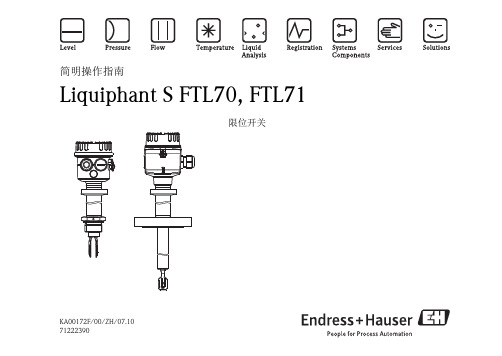
KA00172F/00/ZH/07.1071222390简明操作指南Liquiphant S FTL70, FTL71限位开关目录安全指南3操作4设备标识6应用12测量系统13安装17设置26指示灯信号 30电气连接 31维护和清洁52技术参数53附件55故障排除58备件60维修61补充文档资料62"小心!=禁止;导致不正确操作或损坏。
安全指南Liquiphant S FTL70、FTL71设计用于液体的限位检测。
使用不当可能会导致应用危险。
仅允许经授权的合格专业人员进行Liquiphant S FTL70、FTL71限位开关的安装、电气连接、调试、操作和维护,必须严格遵守《操作手册》、相关标准、法律要求和证书(取决于实际应用)中的要求。
在设备附近安装易于操作的电源开关。
标识电源开关方便设备通断。
C F 2C G 2C G 5C G 6C I 2C I 5C I 6C J 2C M 2C N 2C N 5C N 6C Q 2C U 2C U 5C U 6C 02C 05C 06C 12C 82C 85C 86D G 2D N 2D 82K F 2K F 5K F 6J I S B 2220D N 50,P N 10/16B 1,316L D N 50,P N 25/40B 1,316L D N 50,P N 25/40,A l l o y C 4>1.4462D N 50,P N 63B 2,316L D N 50,P N 63,A l l o y C 4>1.4462D N 50,P N 100B 2,316L D N 80,P N 10/16B 1,316L D N 80,P N 25/40B 1,316L D N 80,P N 25/40,A l l o y C 4>1.4462D N 100,P N 10/16B 1,316L D N 100,P N 63B 2,316L D N 100,P N 63,A l l o y C 4>1.4462D N 80,P N 63B 2,316L D N 80,P N 63,A l l o y C 4>1.4462D N 80,P N 100B 2,316L D N 25,P N 25/40B 1,316L D N 25,P N 25/40,A l l o y C 4>1.4462D N 50,P N 40B 1,316L D N 80,P N 40B 1,316L D N 25,P N 40B 1,316L20K 50,R F ,316L20K 50,R F ,A l l o y C 4>316L D N 50,P N 25/40,A l l o y C 22>1.4462D N 50,P N 63,A l l o y C 22>1.4462D N 80,P N 25/40,A l l o y C 22>1.4462D N 100,P N 63,A l l o y C 22>1.4462D N 80,P N 63,A l l o y C 22>1.4462D N 25,P N 25/40,A l l o y C 22>1.446220K 50,R F ,A l l o y C 22>316L。
Soliphant T FTM20、FTM21级别限位开关说明书

TI389F/24/aeTechnical InformationSoliphant T FTM20, FTM21Level limit switchRobust vibration limit switch for bulk solids,also for dust incendive hazardous areasApplicationSoliphant T is a robust level limit switch for silos with fine-grained or coarse-grained, non-fluid bulk solids.Multiple designs allow the device to be used in various applications. Certificates are also available for use in dust incendive hazardous areas.FTM20: compact design, 10" (250 mm) with vibrating rod for installation in any direction.FTM21: vibrating rod with extension pipe -20 in, 40 in, or 60 in (500 mm, 1000 mm, 1500 mm)for installation in any orientation.Typical applications include: cereals, coffee beans, sugar, animal feed, rice, detergents, dye powder, chalk, gypsum, cement, sand, plastic granules, etc.Your benefits•No calibration: easy commissioning•Insensitive to build-up: maintenance-free operation •No mechanically moving parts: no wear, long operating life•Sensor material 316L SS: minimal abrasion even with materials that tend to build up•Plastic housing with cover and sight glass: switch status visible from outside•Aluminum housing also available •Relays or PNP output•Insensitive to external vibration and flow noises •Available with explosion protection including FM or CSA approvalSoliphant T FTM20/FTM212Endress+HauserTable of contentsFunction and system design. . . . . . . . . . . . . . . . . . . . .3Measuring principle . . . . . . . . . . . . . . . . . . . . . . . . . . . . . . . . . . . 3Measuring system . . . . . . . . . . . . . . . . . . . . . . . . . . . . . . . . . . . . . 3Cable specifications. . . . . . . . . . . . . . . . . . . . . . . . . . .3Cable entries . . . . . . . . . . . . . . . . . . . . . . . . . . . . . . . . . . . . . . . . 3Input . . . . . . . . . . . . . . . . . . . . . . . . . . . . . . . . . . . . . .4Measured variable . . . . . . . . . . . . . . . . . . . . . . . . . . . . . . . . . . . . 4Measuring range (application) . . . . . . . . . . . . . . . . . . . . . . . . . . . . 4Input signal . . . . . . . . . . . . . . . . . . . . . . . . . . . . . . . . . . . . . . . . . 4Output. . . . . . . . . . . . . . . . . . . . . . . . . . . . . . . . . . . . .4Switching delay . . . . . . . . . . . . . . . . . . . . . . . . . . . . . . . . . . . . . . 4Switch behavior . . . . . . . . . . . . . . . . . . . . . . . . . . . . . . . . . . . . . 4Fail-safe mode . . . . . . . . . . . . . . . . . . . . . . . . . . . . . . . . . . . . . . . 4FEM22 electronic insert(DC PNP). . . . . . . . . . . . . . . . . . . . . . . . . . . . . . . . . . .5Power supply . . . . . . . . . . . . . . . . . . . . . . . . . . . . . . . . . . . . . . . . 5Electrical connection . . . . . . . . . . . . . . . . . . . . . . . . . . . . . . . . . . 5Output signal . . . . . . . . . . . . . . . . . . . . . . . . . . . . . . . . . . . . . . . . 5Signal on alarm . . . . . . . . . . . . . . . . . . . . . . . . . . . . . . . . . . . . . . 5Connectable load . . . . . . . . . . . . . . . . . . . . . . . . . . . . . . . . . . . . . 5FEM24 electronic insert(AC/DC with relay output) . . . . . . . . . . . . . . . . . . . . .6Power supply . . . . . . . . . . . . . . . . . . . . . . . . . . . . . . . . . . . . . . . . 6Electrical connection . . . . . . . . . . . . . . . . . . . . . . . . . . . . . . . . . . 6Output signal . . . . . . . . . . . . . . . . . . . . . . . . . . . . . . . . . . . . . . . . 6Signal on alarm . . . . . . . . . . . . . . . . . . . . . . . . . . . . . . . . . . . . . . 6Connectable load . . . . . . . . . . . . . . . . . . . . . . . . . . . . . . . . . . . . . 6Performance characteristics. . . . . . . . . . . . . . . . . . . . .7Reference operating conditions . . . . . . . . . . . . . . . . . . . . . . . . . . . 7Measuring frequency . . . . . . . . . . . . . . . . . . . . . . . . . . . . . . . . . . 7Maximum measured error . . . . . . . . . . . . . . . . . . . . . . . . . . . . . . 7Repeatability . . . . . . . . . . . . . . . . . . . . . . . . . . . . . . . . . . . . . . . . . 7Start-up settling time. . . . . . . . . . . . . . . . . . . . . . . . . . . . . . . . . . 7Installation. . . . . . . . . . . . . . . . . . . . . . . . . . . . . . . . . .7Installation instructions . . . . . . . . . . . . . . . . . . . . . . . . . . . . . . . . . 7Environment . . . . . . . . . . . . . . . . . . . . . . . . . . . . . . . .7Ambient temperature range . . . . . . . . . . . . . . . . . . . . . . . . . . . . . 7Storage temperature . . . . . . . . . . . . . . . . . . . . . . . . . . . . . . . . . . . 7Climate class . . . . . . . . . . . . . . . . . . . . . . . . . . . . . . . . . . . . . . . . 7Degree of protection . . . . . . . . . . . . . . . . . . . . . . . . . . . . . . . . . . . 7Electrical safety . . . . . . . . . . . . . . . . . . . . . . . . . . . . . . . . . . . . . . 7Vibration resistance . . . . . . . . . . . . . . . . . . . . . . . . . . . . . . . . . . . 8Electromagnetic compatibility . . . . . . . . . . . . . . . . . . . . . . . . . . . . 8Process . . . . . . . . . . . . . . . . . . . . . . . . . . . . . . . . . . . .8Environment . . . . . . . . . . . . . . . . . . . . . . . . . . . . . . . . . . . . . . . . 8Thermal shock resistance . . . . . . . . . . . . . . . . . . . . . . . . . . . . . . . 8Limiting medium pressure range. . . . . . . . . . . . . . . . . . . . . . . . . 8State of aggregation . . . . . . . . . . . . . . . . . . . . . . . . . . . . . . . . . . . 8Density. . . . . . . . . . . . . . . . . . . . . . . . . . . . . . . . . . . . . . . . . . . . 8Rod lateral load . . . . . . . . . . . . . . . . . . . . . . . . . . . . . . . . . . . . . . 8Pipe lateral load . . . . . . . . . . . . . . . . . . . . . . . . . . . . . . . . . . . . . . 8Mechanical construction . . . . . . . . . . . . . . . . . . . . . . .9Design, dimensions . . . . . . . . . . . . . . . . . . . . . . . . . . . . . . . . . . . 9Weight . . . . . . . . . . . . . . . . . . . . . . . . . . . . . . . . . . . . . . . . . . . 11Material . . . . . . . . . . . . . . . . . . . . . . . . . . . . . . . . . . . . . . . . . . . 11Human interface . . . . . . . . . . . . . . . . . . . . . . . . . . . .11Operating elements . . . . . . . . . . . . . . . . . . . . . . . . . . . . . . . . . . 11Display elements . . . . . . . . . . . . . . . . . . . . . . . . . . . . . . . . . . . . 11Certificates and approvals . . . . . . . . . . . . . . . . . . . . .12CE mark . . . . . . . . . . . . . . . . . . . . . . . . . . . . . . . . . . . . . . . . . . 12Other standards and guidelines . . . . . . . . . . . . . . . . . . . . . . . . . . 12Hazardous area approval . . . . . . . . . . . . . . . . . . . . . . . . . . . . . . 12Type of protection . . . . . . . . . . . . . . . . . . . . . . . . . . . . . . . . . . . 12Ordering information. . . . . . . . . . . . . . . . . . . . . . . . .13Soliphant T FTM20 . . . . . . . . . . . . . . . . . . . . . . . . . . . . . . . . . . 13Soliphant T FTM21 . . . . . . . . . . . . . . . . . . . . . . . . . . . . . . . . . . 13Accessories . . . . . . . . . . . . . . . . . . . . . . . . . . . . . . . .14Soliphant T. . . . . . . . . . . . . . . . . . . . . . . . . . . . . . . . . . . . . . . . 14Spare parts . . . . . . . . . . . . . . . . . . . . . . . . . . . . . . . . . . . . . . . . . 14Documentation . . . . . . . . . . . . . . . . . . . . . . . . . . . . .15Operating Instructions. . . . . . . . . . . . . . . . . . . . . . . . . . . . . . . . 15Soliphant T FTM20/FTM21Function and system designMeasuring principle A piezoelectric drive excites the vibrating rod of the Soliphant T FTM20 and FTM21 to its resonancefrequency.When the medium covers the vibrating rod, the rod's vibrating amplitude changes (the vibration is damped).Soliphant's electronics compare the actual amplitude with a target value and indicates whether the vibratingrod is vibrating freely or whether it is covered by medium.1. Vibrating amplitude with probe vibrating freely2. Vibrating amplitude with probe coveredMeasuring system Soliphant T is a compact electronic switch.The entire measuring system consists of:•Soliphant T FTM20 or FTM21 with FEM22 or FEM24 electronic insert•a power supply and•the connected control systems, switching units, signalling systems (e.g. lamps, horns, PCS, PLC, etc.)Cable specificationsUse a standard commercial cable max. 18 AWG (max. 2.5 mm2).Note!Use a shielded cable in the event of strong electromagnetic radiation.Endress+Hauser3Soliphant T FTM20/FTM214Endress+HauserCable entries ½" NPT (others on request, please consult factory)InputMeasured variable From 12.5 lb/ft 3 (200 g/l) within the length of the sensor.Measuring range (application)The measuring range depends on the mounting location of Soliphant T and the length of the pipe extension selected. The pipe extension is available in the following lengths: 20 in, 40 in, 60 in (500 mm, 1000 mm,1500 mm).Input signalProbes covered => small amplitude of vibrating rod Probe not covered => large amplitude of vibrating rodOutputSwitching delay0.5 s when the sensor is covered 1 s when the sensor is exposed Switch behavior ON/OFFFail-safe modeMinimum/maximum quiescent current safety can be switched at the electronic insert.Max. = maximum safety (high level):When the vibrating rod is covered, the output switches in the direction of the signal on alarm.For example, used for overfill protection.Min. = minimum safety (low level):When the vibrating rod becomes exposed, the output switches in the direction of the signal on alarm For example, used for dry running protection and empty running protection.Soliphant T FTM20/FTM21Endress+Hauser 5FEM22 electronic insert (DC PNP)Power supplyDC voltage 10 V to 45 V Ripple max. 5 V, 0 to 400 HzCurrent consumption max. 18 mA Power consumption max. 0.81 W Reverse polarity protectedFEM22 overvoltage protection: overvoltage category III Electrical connectionThree-wire direct current connection Output signalSignal on alarm Output signal in event of power failure: < 100 μA Connectable loadLoad switched via transistor and separate PNP connection.Max. 45 V (cyclical overload and short-circuit protection);Continuous max. 350 mA;Max. 0.5 μF for 45 V, max. 1.0 μF for 24 V;Residual voltage < 3 V (for transistor switched through);Residual current < 100 μA (for blocked transistor).Preferred in conjunction with programmable logic controllers (PLC),DI modules as per EN 61131-2.Positive signal at electronics switch output (PNP);Output blocked at level limit.IL< 100 μA L00-FTL2xxxx-07-05-xx-xx-000= Load current(switched through)= Residual current(blocked)= Lit = Not litSoliphant T FTM20/FTM216Endress+HauserFEM24 electronic insert (AC/DC with relay output)Power supplyAlternating voltage 19 V to 253 V, 50/60 Hz or DC voltage 19 V to 55 V Power consumption max. 1.3 W Reverse polarity protectionFEM24 overvoltage protection: overvoltage category III Electrical connectionUniversal current connection with relay output Output signalSignal on alarm Output signal in event of power failure: relay de-energized Connectable loadLoads switched via 2 floating change-over contacts.I~ max. 6 A, U~ max. 253 V;P~ max. 1500 VA, cos ϕ = 1, P~ max. 750 VA, cos ϕ > 0.7;I- max. 6 A to 30 V, I- max. 0.2 A to 125 V.The following applies when connecting a functional extra-low voltage circuit with double insulation as per IEC 1010: Sum of voltages of relay output and power supply max. 300 VOutput:When connecting a device withhigh inductance, provide a spark arrester to protect the relay contact.A fine-wire fuse (depending on the load connected) protects the relay contact in the event of a short-circuit.Both relay contacts switch simultaneously.DPDT (double pole double throw)*When jumpered, therelay output works with NPN logic.** Please refer to "Connectable load" section Note! Please note the different voltage ranges for direct and alternating current.L00-FTL2xxxx-07-05-xx-xx-001= Relay energized = Relay de-energized = Lit = Not litSoliphant T FTM20/FTM21Endress+Hauser7Performance characteristicsReference operating conditionsAmbient temperature: 68°F (20°C)Process temperature: 68°F (20°C)Medium: ABS granules 38 to 42 lb/ft 3 (610 to 680 g/l)Grain size: 0.08" to 0.14" (2 to 3.5 mm)Pressure: atmosphericSensor installation: vertical from above or below; horizontal from the side Measuring frequency 700 to 800 Hz Maximum measured error ≤ 0.20" (5 mm)Repeatability < 0.04" (1 mm)Start-up settling time< 3 sInstallationInstallation instructionsMounting locatione.g. storage or buffer container OrientationHorizontal installation/vertical installation* With protective cover (to be provided by customer)** With protecting tube (to be provided by customer)EnvironmentAmbient temperature range -40 to +158°F (-40 to +70°C)Storage temperature -40 to +185°F (-40 to +85°C)Climate class Tropicalized as per DIN IEC 68 Part 2-38Degree of protection NEMA 4X (F18 Aluminum housing), IP66/IP67 (F16, F18 housing)Electrical safetyIEC 61010, CSA 1010.1-92, FM3600Soliphant T FTM20/FTM218Endress+HauserVibration resistanceDIN 60068-2-27 / IEC 68-2-27: shock 50 g; vibration 0.05 g 2/Hz Electromagnetic compatibilityInterference emission to EN 61326, Electrical Equipment Class B Interference immunity to EN 61326, Annex A (Industrial)ProcessEnvironmentPermitted ambient temperature T 1 at housing depending on the medium temperature T 2 in the container:Thermal shock resistance 120 KLimiting medium pressure range-14.5 to 362 psi (-1 to 25 bar)State of aggregation SolidsDensityBulk solids weight: ≥ 12.5 lb/ft 3 (200 g/l), not fluidized Grain size: ≤ 0.98" (25 mm)Rod lateral load ≤ 101 lbf (450 N)Pipe lateral load≤ 22.5 lbf per 3 ft of pipe (160 N per 1 m)Soliphant T FTM20/FTM21Mechanical constructionDesign, dimensions Compact version, aluminum housing, FTM 20Pipe extension, aluminum housing, FTM 21x = 20 in,40 in, or60 in (500 mm,1000 mm,or 1500 mm)Endress+Hauser9Soliphant T FTM20/FTM21 Design, dimensions Compact version, plastic housingPipe extension, plastic housingx = 20 in,40 in, or 60 in (500 mm,1000 mm, or1500 mm)10Endress+HauserEndress+Hauser 11Weight FTM20/FTM21 with F16 housing, FEM24 and R1" thread:Material Sensor 316L SS F16 housingPTB-FR, cover with sight glass made of PA12, EPDM cover seal F18 housingAluminum EN-AC-AlSi10Mg, plastic-coated EPDM cover seal Process connections •1¼ - 11½ NPT •1½ - 11½ NPTOther process connections available, please consult factory.Human interfaceOperating elementsFEM22, FEM24One switch to set maximum or minimum detection (see also fail-safe mode on Page 4)One switch to set the density of the bulk solids, > 25 lb/ft 33Display elementsFEM22FEM24Compact= 2 lb (963 g)20" (500 mm)= 3 lb (1325 g)40" (1000 mm)= 4 lb (2011 g)60" (1500 mm)= 6 lb (2607 g)L00-FEM22xxx-07-05-xx-xx-001One green LED: operationOne yellow LED: electronic switch closedL00-FEM24xxx-07-05-xx-xx-002One green LED: operationOne yellow LED: contact closed (relay energized or fed with current)Certificates and approvalsCE mark Soliphant T meets the statutory requirements of the EC Directives. Endress+Hauser confirms successful testingof the device by affixing the CE mark.Other standards and guidelines Other standards and guidelines that were taken into consideration in designing and developing Soliphant T FTM20, FTM21:•Low Voltage Directive (73/23/EEC)•DIN EN 61010 Part 1, 2001Protection Measures for Electrical Equipment for Measurement, Control, Regulation and Laboratory ProceduresPart 1: General requirements•EN 61326Electrical Equipment for Measurement, Control and Laboratory UseEMC requirementsEx approval Your Endress+Hauser sales center can provide you with information on the hazardous area versions which cancurrently be delivered (FM, etc.).All explosion protection data are given in separate documentation which is available upon request.Type of protection•FM DIP, Dust ignition proof Class II, III; Division 1; Groups E, F, G (for aluminum housing)•CSA DIP, Dust ignition proof Class II, III; Division 1; Groups E, F, G (for aluminum housing)•ATEX II 1/3 D12Endress+HauserOrdering informationSoliphant T FTM20 Soliphant T FTM2110ApprovalA Non-hazardous areaC CSA General Purpose, CSA C USD CSA DIP (Dust ignition proof), Class II, III; Div. 1, Grps. E, F, G (aluminum housing)FM DIP (Dust ignition proof), Class II, III; Div. 1, Grps. E, F, G (aluminum housing) Y Special version20Process connection *M Thread, ANSI NPT 1¼",316L SSN Thread, ANSI NPT 1½",316L SSY Special version* Other process connections available, please consult factory30Electronics; output2FEM22:3-wire PNP,10 to 45 V DC4FEM24:Relay DPDT,19 to 253 V AC or 10 to 55 V DC9Special version40Housing; cable entry3F16Polyester IP66/IP67Thread, NPT ½"6F18Aluminum NEMA 4X (IP66/IP67)Thread, NPT ¾"9Special version50Additional fittingsA Basic versionY Special versionFTM20Complete product designation10ApprovalA Non-hazardous areaC CSA General Purpose, CSA C USD CSA DIP (Dust ignition proof), Class II, III; Div. 1, Grps. E, F, G (aluminum housing)FM DIP (Dust ignition proof), Class II, III; Div. 1, Grps. E, F, G (aluminum housing) Y Special version20Process connection *M Thread, ANSI NPT 1¼",316L SSN Thread, ANSI NPT 1½",316L SSY Special version* Other process connections available, please consult factory25Sensor length620 inch740 inch860 inch9Special version30Electronics; output2FEM22:3-wire PNP,10 to 45 V DC4FEM24:Relay DPDT,19 to 253 V AC or 10 to 55 V DC9Special version40Housing; cable entry3F16Polyester IP66/IP67Thread, NPT ½"6F18Aluminum NEMA 4X (IP66/IP67)Thread, NPT ¾"9Special version50Additional fittingsA Basic versionY Special versionFTM21Complete product designationEndress+Hauser1314Endress+HauserAccessoriesSoliphant TSpare parts•FEM22 electronic insert TN 52025688•FEM24 electronic insert TN 52025691•Plastic cover with sight glass with seal TN 52025790•Aluminum cover with seal TN 52005910•Sliding sleeve, pressurized R 1½: TN 52023312NPT 1½-11½:TN 52025090Note!Suitable for multiple switch-point configurations•Sliding sleeve, non-pressurized, IP65R 1½: TN 52023313NPT 1½-11½:TN 52024578Note!Only suitable for one-time switch-point configuration!DocumentationOperating Instructions•Soliphant T FTM20, FTM21KA227F/00/a6Endress+Hauser15United States Endress+Hauser, Inc. 2350 Endress Place Greenwood, IN 46143 Tel. 317-535-7138 Sales 888-ENDRESS Service 800-642-8737 fax 317-535-8498******************.com TI 389F/24/ae/04.08© 2008 Endress+HauserMexicoEndress+Hauser, México, S.A. de C.V.Fernando Montes de Oca 21 Edificio A Piso 3Fracc. Industrial San Nicolás54030. Tlalnepantla de BazEstado de MéxicoTel: +52 55 5321 2080Fax +52 55 5321 2099********************.comCanadaEndress+Hauser Canada1075 Sutton DriveBurlington, ON L7L 5Z8Tel. 905-681-9292800-668-3199Fax 905-681-9444***************.com。
E+H音叉开关FTM20 FTM21

过程条件 . . . . . . . . . . . . . . . . . . . . . . . . . . . . . . . . . . . 8 环境条件 . . . . . . . . . . . . . . . . . . . . . . . . . . . . . . . . . . . . . . . . . . 8 抗热冲击 . . . . . . . . . . . . . . . . . . . . . . . . . . . . . . . . . . . . . . . . . . 8 介质压力范围 . . . . . . . . . . . . . . . . . . . . . . . . . . . . . . . . . . . . . . 8 聚集状态 . . . . . . . . . . . . . . . . . . . . . . . . . . . . . . . . . . . . . . . . . . 8 颗粒大小 . . . . . . . . . . . . . . . . . . . . . . . . . . . . . . . . . . . . . . . . . . 8 固料密度 . . . . . . . . . . . . . . . . . . . . . . . . . . . . . . . . . . . . . . . . . 8 横向负载 . . . . . . . . . . . . . . . . . . . . . . . . . . . . . . . . . . . . . . . . . . 8
E+H Soliphant T FTM50 FTM51 限位开关简明操作指南
A PTFE>316L; ৹փᑖ⎲ቲ
B PTFE>316L; ⎲ޘቲ
C ETFE>316L; ⎲ޘቲ
2 5
316L; 316L;
Ra ≤ Ra ≤
3.2 μm/80 grit, *1
0.8 μm/180 grit;
৹փᣋݹ
7 316L; Ra ≤ 0.8 μm/180 grit; ৹փᣋݹ
5 FEM55; 8/16 mA, 11...36 V DC
7 FEM57; PF M
8 FEM58; NAMUR +
⍻䈅᤹䫞
9 *2
11
12
A аփᔿԚ㺘
D E G
6 20
6
m> ft > m,
**33
H
䬐㻵 20 ft,
>
*3
Y
䬐㻵
*2
>
*3
H T13,䬍,IP66/68 NEMA4X, ࠶ර᧕㓯㞄
9 *2
A 155 mm/6 in; min. 10 g/l (0.7 lbs) K 100 mm/4 in; min. 50 g/l (3 lbs)
Y *2
1 FEM51;
19...253 V AC
2 FEM52; PNP , 10...55 V DC
4 FEM54; DPDT , 19...253 V AC / 55 V DC
CSA C U S
D FM DIP-AI S Cl. II, III, Div. 1, G r. E- G +
CSA DIP C l. II, III, Div. 1+2, Gr. E -G
E IE C E x iaD A20
蜂巢钢限位开关说明书

DESCRIPTIONWhen the application requires an industrial grade limit switch where wet, dust, or corrosive environments may be present, Honeywell offers the LS2 Series of stainless steel limit switches. The limit switch body and actuating heads are cast from 316 stainless steel. These limit switches are available with a wide variety of actuating heads with a one-pole or two-pole snap-action double-break contact block. A threaded conduit isintegral to the switch body with terminal screws for each wiring point on the contact block. Honeywell can provide the switches factory wired for reduced installation. The limit switches can also be factory wired with the limit switch body epoxy encapsulated, minimizing any dust or liquid migrating to the switch contacts. The limit switches can be front mounted with two through holes or rear mounted with two integral threaded holes from the back side.As with the other HDLS Series of limit switches, the LS2 Series have UL, CSA, CE, UKCA and CCC certifications for global acceptance.VALUE TO CUSTOMERS• Harsh-duty stainless steel switch withstands many tough environments including dust, dirt, grime, heat, and washdown areas• Variety of actuator heads and switch options• Threaded conduit or factory wired • Silver contacts or optional gold-plated contacts• Made in the USA FEATURES• 316 Series stainless steel actuating heads and body with stainless steel screws• Designed to IP 65/66/67 and NEMA 1, 3, 3R, 4, 4X, 6, 6P, 12, and 13• Diaphragm seal between head and body provides an extra degree of sealing• Fluorocarbon seals standard for chemically harsh environments and/or higher temperature applications (121 °C/250 °F)• Optional fluorosilicone seals for low temperature(-40 °C/-40 °F) applications• Available with 1NC/1NO or 2NC/2NO double break contacts. Same polarity for each pole (Za)• Side rotary head with center neutral or sequential switch design available • Actuator heads can be field rotated to any of four positions 90° apart• Side rotary heads are factory adjusted for CW and CCW actuation of the switch. Heads can be field adjusted for CW only or CCW only to actuate the switch• CCC, CE, UKCA, CSA, and UL certifications for global acceptanceHDLS LS2 SERIESMICRO SWITCH Heavy-Duty Limit Switch (Stainless Steel)002426 Issue 2APPLICATIONS• Food processing plants• Petrochemical plants• Power generating plants• Pulp and paper mills• Shipboard and dockside locations • Transportation hubs and facilities• Water treatment and wastewater treatment facilities DIFFERENTIATION• Stainless steel housing designed for corrosive and adverse environments • All-metal drive chain for consistent operating characteristics• Three different electrical connectivity options; threaded conduit, factory wired, or factory wired with epoxy encapsulated body• Side rotary head incorporates stainless steel shaft with bronze bearing for increased mechanical life of up to 50 million operations• Wide selection of stainless steel levers to compliment the side rotary limit switchFigure 1. Product Nomenclature: Stainless Steel Version LS2Switch Type LS2 Series Limit Switchhousing, fluorocarbonseals,with orwithoutfactory wiringOpt. Factory Wiring(RequiresAActuator Heads(unless noted, all side rotary4KContact Block &TerminationCFigure 2. Product Nomenclature: Low Temperature VersionsFigure 3. Product Nomenclature: Factory Sealed VersionsLS2Switch TypeLS2 Series Limit Switch housing, fluorocarbonseals, and factory sealedNOTE: Not all combinations of model codes are available. Please contact your local Honeywell provider for assistance.Factory SealedAActuator Heads(unless noted, all side rotary4LContact Block &TerminationX-FPLS2Switch TypeLS2 SeriesLimit Switchhousing,with low temp.seals, with orwithoutfactorywiringNOTE: Not all combinations of model codes are available. Please contact your local Honeywell provider for assistance.MActuator Heads(unless noted, all side rotary4NContact Block & TerminationSealsBOpt. Factory Wiring(RequiresMSIDE ROTARY: Available levers provide greater versatility. Actuating heads may be indexed in any of four positions, 90° apart. All are momentary action except maintained head (LSN Series).LSN - Maintained contact: rotation and reset on clockwise rotation, and vice versa. LSH - Low torque, low differential travel: operating torque and narrow differential travel. 68° minimum overtravel.LSL - Sequence action: two poles. 48° minimum overtravel.LSM - Center neutral: TOP PLUNGERS: Available with 4,83 mm [0.19 in] minimum overtravel. Top pin plungers are offered in pin plunger, anadjustable plunger, and a roller plunger.SIDE PLUNGERS: Available with 4,83 mm [0.19 in] minimum overtravel. Side plungers are offered in a pin plunger and aroller plunger.MICRO SWITCH HDLS SERIES ACTUATOR HEADSNOTE: The pre-wired cable or mini-style connector have a temperature rating of -20 °C to 105 °C [-4 °F to 221 °F]. When temperature extremes are involved, the application should be reviewed to ensure cable or connector suitability.Figure 6. 4KC, 4KPC, 4KP-FP 1NC/1NO with 5-conductor cableWIRING DIAGRAMSWhiteGreen = GroundBlack Orange RedSame polarityFigure 5. 3E, 3K, 4K 1NC/1NOGreen internal screw= GroundSame polarityFigure 8. 4LM, 4LX-FP2NC/2NO with 9-conductor cableFigure 7. 4L 2NC/2NOYellow Red Same polarity each poleOrange Brown BlackBlue WhitePinkSamepolarity each poleFigure 10. 4MM, 4MX-FP2NC/2NO sequential with 9-conductor cableFigure 9. 4M2NC/2NO sequentialYellow Red Same polarity each poleOrange Brown Black Blue WhitePink 12nd 12nd Same polarity each poleFigure 12. 4NM, 4NX-FP2NC/2NO center neutral with 9-conductor cableFigure 11. 4N2NC/2NO center neutralYellow Red Same polarity each poleOrange Brown Black Blue WhitePink CW CW Same polarity each poleNote: Wiring diagrams for limit switches with maintained contacts are illustrated with lever/shaft in CW position.ELECTROMECHANICAL SWITCHES Definitions below explain the meaning of operating characteristics. Characteristics shown in tables were chosen as most significant. They are taken at normal room temperature and humidity. These may vary as temperature and humidity conditions differ. Sketches show how characteristics are measured for in-line plunger actuation and rotary actuation.Linear dimensions for in-line actuation are from top of plunger to a reference line, usually the center of the mounting holes. Rotary actuated HDLS limit switches have the characteristics in degrees of angular rotation.Differential Travel (D.T.) – Plunger or actuator travel from point wherecontacts ‘‘snap-over’’ to point where they ‘‘snapback.’’Free Position (F.P.) – Position of switch plunger or actuator when no external force is applied (other than gravity).Full Overtravel Force – Force required to attain full overtravel of actuator.Operating Position (O.P.) – Position of switch plunger or actuator at which point contacts snap from normal to operated position. Note that in the case of flexible or adjustable actuators, the operating position is measured from the end of the lever or its maximum length. Location of operating position measurement shown on mounting dimension drawings.Operating Force (O.F.) – Amount of force applied to switch plunger or actuator to cause contact ‘‘snap-over.’’ Note in the case of adjustable actuators, the force is measured from the maximum length position of the lever.Overtravel (O.T.) – Plunger or actuator travel safely available beyond operating position.Pretravel (P.T.) – Distance or angle traveled in moving plunger or actuator from free position to operating position.Release Force (R.F.) – Amount of force still applied to switch plunger or actuator at moment contacts snap from operated position to unoperated position.Total Travel (T.T.) – Distance fromactuator free position to overtravel limitposition.Bar Chart Description (Inline and Rotary)> Actuation< ReleaseNC = Normally closed contact(s)NO = Normally open contact (s)LS2Z51ALS2Z52A Adjustable RodLS2Z54NMICRO SWITCH HDLS Side Rotary Levers’ Cam TrackingLevers for side and top rotary switches are normally ordered as separate catalog listings. They also may be ordered by including a suffix to the switch catalog listing (see nomenclature tree in this document) and adding the lever price. Figure 13. LS2Z51 Type Levers Cam TrackingFigure 14. LS2Z52 Type Levers Cam TrackingFigure 15. LS2Z54 Type Levers Cam TrackingADJUSTMENTLSZ51 TYPE LEVERS CAM TRACKING adjustment[0.43 in]OR OR adjustmentFigure 16. LS2 Series Side Rotary (mm [in])Figure 17. LS2 Series Side Rotary with Cable (mm [in])Figure 18. LS2 Series Top Pin Plunger (mm [in])Figure 19. LS2 Series Top Roller Plunger (mm [in])8,6 [0.34]31,75 [1.25]across flats31,0[1.22]Ø 5,1 / 0.20MOUNTING HOLES (2)47,81.8839,61.5614,70.5825,41.0036,61.44122,94.8486,63.4159,42.3419,10.7529,51.16)TAPPED FROM REAR ONLY7,9 / 0.31 MIN DEP62,02.4493,73.69MTG. PADSØ 9,6 / 0.38 DIA x 6,4 / 0.25 DEEP COUNTERBORE (2)21,30.8421,30.8438,11.5045,21.7847,8[1.88]29,5 [1.16]across flats8,1 [0.32]Figure 20. LS2 Series Side Plunger (mm [in])45,2FOR MORE INFORMATION Honeywell Sensing and Safety Technologies services its customers through a worldwide network of sales offices and distributors. For application assistance, current specifications, pricing or the nearest Authorized Distributor, visit our website or call:USA/Canada +1 302 613 4491Latin America +1 305 805 8188 Europe +44 1344 238258 Japan +81 (0) 3-6730-7152 Singapore +65 6355 2828 Greater China +86 4006396841HoneywellSensing and Safety Technologies830 East Arapaho RoadRichardson, TX 75081 WARRANTY/REMEDYHoneywell warrants goods of its manufactureas being free of defective materials andfaulty workmanship during the applicablewarranty period. Honeywell’s standard productwarranty applies unless agreed to otherwise byHoneywell in writing; please refer to your orderacknowledgment or consult your local salesoffice for specific warranty details. If warrantedgoods are returned to Honeywell during theperiod of coverage, Honeywell will repair orreplace, at its option, without charge thoseitems that Honeywell, in its sole discretion,finds defective. The foregoing is buyer’s soleremedy and is in lieu of all other warranties,expressed or implied, including those ofmerchantability and fitness for a particularpurpose. In no event shall Honeywell beliable for consequential, special, or indirectdamages.While Honeywell may provide applicationassistance personally, through our literatureand the Honeywell web site, it is buyer’s soleresponsibility to determine the suitability ofthe product in the application.Specifications may change without notice.The information we supply is believed tobe accurate and reliable as of this writing.However, Honeywell assumes no responsibilityfor its use.m WARNINGPERSONAL INJURYDO NOT USE these products as safetyor emergency stop devices or in anyother application where failure of theproduct could result in personal injury.Failure to comply with theseinstructions could result in death orserious injury.m WARNINGMISUSE OFDOCUMENTATION• The information presented in thisproduct sheet is for reference only.Do not use this document as aproduct installation guide.• Complete installation, operation,and maintenance informationis provided in the instructionssupplied with each product.Failure to comply with theseinstructions could result in death orserious injury.002426-2-EN | 2 | 11/22。
流量开关操作手册

间,取决于流体的流速.
第二种情况: 现场不可以模拟实际的报警流量点(现场管道内的流量不可调或者不知道实际 的流量值)
的位置 LED 灯常亮----检查探头的电阻值是否在规定范围内,如果
超出范围请更换探头 把 HEATER/HTR 拨到”-”的位置 LED 灯暗----把 HEATER/HTR 处于”+”的位置同时 FAULT/FLT 处于”OFF”位置,或者把 HEATER/HTR 放在“-”
的位置 LED 灯长亮----检查探头的电阻值是否在规定范围内,如果
开关指示错误(红色 LED 报警灯会闪 烁)
工作状况 气体流量检测 液体液位—探头湿
液体液位—探头干
液体流量—探头干或 者气体流量—无
液体流量—探头湿无 流量
液体流量—实际流量
气体流量—实际流量
方法 确保探杆延伸到流量中. 改变 HEATER(FS)/HTR(FS2) 到’’-” 检查 HEATER(FS)/HTR(FS2)是否设在“-”的位置 改变 HEATER/HTR 的位置为”+” LED 灯 暗----联系工厂解决 LED 灯 一直亮----检查探头的电阻值是否在规定范围内,如 果超出范围请更换探头 检查 HEATER(FS)/HTR(FS2)是否设在“-”的位置 把 FAULT(FS)/FLT(FS2)处于”OFF”位置 LED 灯暗----工作在这种模式下 LED 灯一直亮----检查探头的电阻值是否在规定范围内,如 果超出范围请更换探头 把 FAULT(FS)/FLT(FS2)处于”OFF”位置 LED 灯暗----把 HEATER/HTR 处于”+”的位置同时 FAULT/FLT 处于”OFF”位置,或者把 HEATER/HTR 放在“-”
E+H Soliphant T FTM20 FTM21 限位开关简明操作指南
90
150 T2*
°C
x °C = (1.8 x + 32) °F
䗷〻䘎᧕䱴Ԧ
pe = max. 25 bar (363 psi) *
പᯉᇶᓖ
䉧㋂བྷሿ
i
min. 200 g/l
5l
1.0
kg
ø max. 25 mm
(max. 1.0 in)
Endress + Hauser
25
滑动套管 常压操作, IP65
5 F18 , IP66/67; M20
6 F18 , IP66/67; NPT ¾
7 F18 , IP66/67; G ½
F18
9 *2
䬍
A สᵜර
Y *2
*1 ᰐ *2 ަԆ
9
应用 固料中的限位检测
* 防护罩 或 ** 保护管
10
*
**
Endress + Hauser
⭥ᆀᨂԦ
䇒䍗ਧ˖ FTM20 - # # # # #
3
Endress + Hauser
操作 握住外壳、法兰或延长管。
4
Endress + Hauser
禁止弯曲 禁止截短 禁止拉伸
Endress + Hauser
5
设备标识
6
ENDRESS+HAUSER Soliphant T
䇒䍗ਧ FTM20– # # # # #
A C
C*1SA䙊⭘රˈCS A C US
A DIN 2999 R 1
316L
G DIN 2999 R 1 ½ 316L
M ANSI
NP T 1¼ 316L
N ANSI
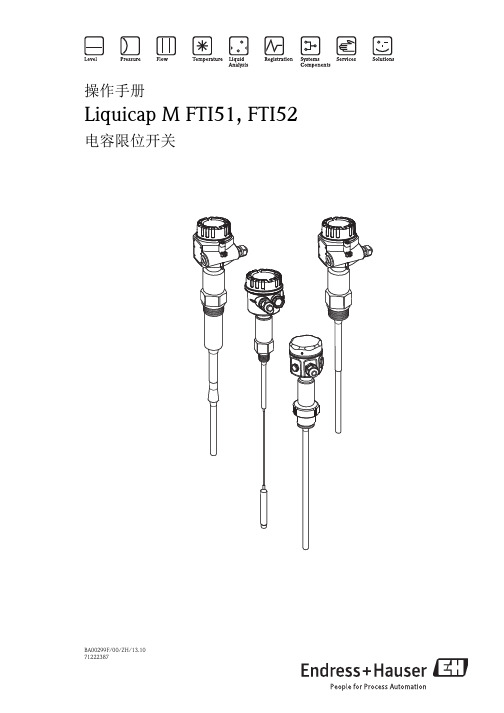
E+H Liquicap M FTI51 FTI52 电容限位开关操作手册
6 调试 . . . . . . . . . . . . . . . . . . . . . . . . . . 46
6.1 安装和功能检查 . . . . . . . . . . . . . . . . . . . . . . . . . 46 6.2 调试电子插件 FEI51、 FEI52、 FEI54、 FEI55 . 46 6.3 调试电子插件 FEI53 或 FEI57S . . . . . . . . . . . . . 62 6.4 调试电子插件 FEI58 . . . . . . . . . . . . . . . . . . . . . . 64
3 安装 . . . . . . . . . . . . . . . . . . . . . . . . . . 13
3.1 快速安装指南 . . . . . . . . . . . . . . . . . . . . . . . . . . . 13 3.2 到货验收和储存 . . . . . . . . . . . . . . . . . . . . . . . . . 13 3.3 安装指南 . . . . . . . . . . . . . . . . . . . . . . . . . . . . . . 14 3.4 测量条件 . . . . . . . . . . . . . . . . . . . . . . . . . . . . . . 16 3.5 安装实例 . . . . . . . . . . . . . . . . . . . . . . . . . . . . . . 16 3.6 分离型外壳 . . . . . . . . . . . . . . . . . . . . . . . . . . . . . 21 3.7 不带自动粘度补偿功能的传感器 . . . . . . . . . . . 23 3.8 带自动粘度补偿功能的传感器 . . . . . . . . . . . . . 25 3.9 安装指南 . . . . . . . . . . . . . . . . . . . . . . . . . . . . . . 27 3.10 安装后检查 . . . . . . . . . . . . . . . . . . . . . . . . . . . . . 29
限位开关产品说明说明书

• High mechanical resistance • Degree of protection IP66• Zinc alloy (Zamack) body • Positive Opening Operation• Minimum Force to achieve Positive Opening Operation • Precise operating points (consistency)• Immune to electromagnetic disturbances• Zb type contact blocks • Current Ith = 10A• Rated insulation voltage Ui = 500V • UL, CSA, CE• Conform with IEC 947-5-1 (EN 60947-5-1)They are developped in order to be used for following operations:• Presence/Absence• Positioning and travel limit• Objects passing/countingLimit Switches - Limit Type Metal Body IP66Product DescriptionDescription of the key codesRated insulation voltage U i-according to IEC 60947-1 and EN 60947-1 400V (PS21, PS42), 500V (PS31, PS43) (degree of pollution 3)-according to UL 508, CSA C22-2 n°14A 300 Q 300 (PS21, PS42),A 600 Q 600(PS31, PS43)Rated impulse withstand voltage U impkV 6(according to IEC 60947-1 and EN 60947-1)Conventional enclosed thermal current I theA 10(according to IEC 60947-5-1 and EN 60947-5-1) (θ≤40°C)Short-circuit protection - gG type fuses A 10Rated operational current I e / AC-15- acc.to IEC 60947-5-124Vac (50/60 Hz)A 10130Vac (50/60 Hz)A 5.5230Vac (50/60 Hz)A 3.1240Vac (50/60 Hz)A 3400Vac (50/60 Hz)A 1.8- acc.to UL 508, CSA C22 n°14A 300 (PS21, PS42), A 600 (PS31, PS43)I e / DC-13- acc.to IEC 60947-5-124Vdc A 2.8110Vdc A 0.6250VdcA0,27- acc.to UL 508, CSA C22 n°14Q 300 (PS21, PS42), Q 600 (PS31, PS43)Electrical durability (according to IEC 60497-5-1 annex C)Utilization categories AC-15 and DC-13 (see curves and value below)- max. switching frequency Cycles/h 3600- load factor0,5Connecting data of contact blocks Connecting terminalsM3,5 (+,-) pozidriv 2 screw with cable clamp Connecting capacity 1 or 2 x mm2 / AWG 0,5mm2 / AWG 20 to 2,5mm2 / AWG 14Terminal marking According to EN 50013PositivityContacts with positive opening operation as per IEC 60947-5-1 chapter 3StandardsIEC 60947-1, IEC 60947-5-1, EN 60947-1, EN 60947-5-1, UL508 and CSA C22-2 n°14Certifications – ApprovalsUL – CSAAir temperature near the device - during operation °C -25 … +70- for storage°C -30 … +80Climatic withstand According to IEC 68-2-3 and salty mist according to IEC 68-2-11Mounting positionsAll positions are authorized Shock withstand (according to IEC 68-2-27 and 60068-2-27)g 50g*(1/2sinusoidal shock for 11 ms) no change in contact positionResistance to vibrations (acc.to IEC 68-2-6 and EN 60068-2-6)g25g (10…500Hz) no change in position of contacts greater than 100µs Protection against electrical shocks (acc.to IEC 536)Class I Degree of protection (according to IEC 529 and EN 60529)IP66Consistency (measured over 1 milion operations)0.1 mm (upon closing point)Technical DataElectrical Data* except for PS21/PS42 with head type W0, W1: 25g.Limit Switches - Limit Type (PS21)Metal Body IP66A M 1Cable GlandConformity /Limit Switches - Limit Type (PS21)Metal Body IP66Cable GlandA M 1Utilization precautionsUtilization precautionsElectrical connection and mountingCorrect Incorrect Incorrect AdjustementPosition adjustement of lever and head。
海克斯康机器操作说明书
海克斯康机器操作说明书 Prepared on 24 November 2020NO. 操作说明图片1 1.每天开机前,必须先检查供气压力是否达到要求,如果达到,方可开控制柜。
检查气压时,还需看下过滤器内是否有水和油,当杯中的油水混合物达到5mm时,需手动将水和油放干净。
只需旋开过滤器下的黑色的阀即可(具体气压要求见右方)。
如滤杯中的滤芯太脏,则需要通知机修更换滤芯。
每台机器的气压表都在机器的右下方。
CMM1气压: Mpa CMM3气压: barCMM2气压: Mpa CMM5气压: Mpa图(1)气压表过滤油的过滤水的排放阀22、测量室的温湿度要求温度必须在:20±2℃湿度必须在:50±10%RH如果温湿度没有在上述范围内,请及时上报主管,并调整空调温度或相应措施。
图(2)温湿指示针温湿指示针5保养机台所用的擦拭布必须是高织纱纯棉布或无尘布,酒精必须是无水酒精,注意,严禁使用酒精擦拭机台喷漆表面及Renishaw光栅。
图(12)控制柜上必须保证无铝削,以防止铝削不慎掉入控制柜内,长时间高温,导致主板烧掉。
图(11)图(11) 图(12)台面上的正确放置66、操作盒的使用和注意事项使用操作盒是,应注意操作盒的操作杆在旋转时是否有旋不动,或很难旋,或还没旋Z轴就直接下滑现象,如有上述现象,需立即和技术员反映,技术员将对操作杆进行更换。
在测量打点时,快接近踩点位置时,需按减速键。
如操作面板有破损时,请及时和技术员反映,将进行面板更换。
图(13)SLOW键--控制手动采点测头慢速移动,防止打点有回旋型箭头标志的↓键--控制测头前后运动SPEED键--控制测头移动速度的,按↑标记说明是加速度,按↓标记说明是减←→键--控制测头左右移动紧急按钮键—一般不用,出现紧急事情时才DONE键--确认键当采点结束需操作杆--控制测头上下左右运动ENABLE键--测头须运动时和黑色操作杆结合用,缺一MACHSTART键键--开机时用来加电的,测量过程中测针撞停后,绿灯不亮时,需要加电。
E+H Solicap M FTI55 FTI56 电容限位开关操作手册

4.1 推荐连接 . . . . . . . . . . . . . . . . . . . . . . . . . . . . . . . 36 4.2 在 F16、 F15、 F17、 F13 外壳中接线 . . . . . . . 38 4.3 在 T13 外壳中接线 . . . . . . . . . . . . . . . . . . . . . . . 39 4.4 连接设备 . . . . . . . . . . . . . . . . . . . . . . . . . . . . . . . 40 4.5 防护等级 . . . . . . . . . . . . . . . . . . . . . . . . . . . . . . . 40 4.6 连接电子插件 FEI51
( 交流 (AC) 供电,两线制连接 ) . . . . . . . . . . . . . 41 4.7 连接电子插件 FEI52
( 直流 (DC) 供电, PNP) . . . . . . . . . . . . . . . . . . . 42 4.8 连接电子插件 FEI53 ( 三线制连接 ) . . . . . . . . . . 43 4.9 连接电子插件 FEI54
Solicap M FTI55, FTI56
电子插件:FEI53、 FEI57S
A 1
FEI5x
ḽ
-+
B 2
0...1600pF 0.....500pF
概述
LED示⚥ Ӟ䎧 䰚⛱ ➴⚝
LED 指示灯 1 工作 :每 5 s 闪烁一次
FTL20液体限位开关
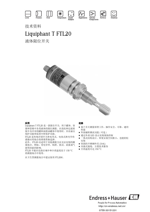
性能参数 . . . . . . . . . . . . . . . . . . . . . . . . . . . . . . . . . . . 8 开关切换延迟时间 . . . . . . . . . . . . . . . . . . . . . . . . . . . . . . . . . . 8 参考操作条件 . . . . . . . . . . . . . . . . . . . . . . . . . . . . . . . . . . . . . . . 8 测量值分辨率 . . . . . . . . . . . . . . . . . . . . . . . . . . . . . . . . . . . . . . . 8 工作频率 . . . . . . . . . . . . . . . . . . . . . . . . . . . . . . . . . . . . . . . . . . 8 最大测量误差 . . . . . . . . . . . . . . . . . . . . . . . . . . . . . . . . . . . . . . . 8 重复性 . . . . . . . . . . . . . . . . . . . . . . . . . . . . . . . . . . . . . . . . . . . . 8 迟滞性 . . . . . . . . . . . . . . . . . . . . . . . . . . . . . . . . . . . . . . . . . . . . 8 稳定时间 . . . . . . . . . . . . . . . . . . . . . . . . . . . . . . . . . . . . . . . . . . 8 环境温度的影响 . . . . . . . . . . . . . . . . . . . . . . . . . . . . . . . . . . . . . 8 介质温度的影响 . . . . . . . . . . . . . . . . . . . . . . . . . . . . . . . . . . . . . 8 介质压力的影响 . . . . . . . . . . . . . . . . . . . . . . . . . . . . . . . . . . . . 8
E+H Liquiphant M FTL51C 限位开关简明操作指南

KA00162F/00/ZH/07.1071222389
简明操作指南
Liquiphant M FTL51C
限位开关
目录
安全指南3操作4设备标识6应用10测量系统11安装15设置24指示灯信号 28电气连接 29维护50技术参数51故障排除52备件54维修55补充文档资料56
"小心!
=禁止;
导致不正确操作或损坏。
安全指南
Liquiphant M FTL51C设计用于液体的限位检测。
使用不当可能会导致应用危险。
仅允许经授权的合格专业人员进行Liquiphant M FTL51C的安装、电气连接、调试、操作和维护,必须严格遵守《操作手册》、相关标准、法律要求和证书(取决于实际应用)中的要求。
在设备附近安装易于操作的电源开关。
标识电源开关方便设备通断。
E+H技术手册FTM50_FTM51_FTM52

深圳市百合顺电子科技有限公司
Soliphant M FTM50, FTM51, FTM52
电源 电气连接
电子插件FEM55—(8/16 mA)
·直 流电 压 :11...36 V DC ·功 率消 耗 :< 600 mW ·极 性反接 保护 ·隔 离电 压 :3.6 kV ·FEM55的过 压 保护 :过 压保 护等 级III
5
深圳市百合顺电子科技有限公司
电源 电气连接
Soliphant M FTM50, FTM51, FTM52
电子插件FEM54—带继电器输出的AC/DC连接
·交 变电 压 :19...25 3 V,50/ 60 Hz或交 流 电压 :19 ...55 V ·功 率消 耗 :m ax. 1 .5 W ·极 性反接 保护 ·隔 离电 压 :3.6 kV ·FEM54的过 压 保护 :过 压保 护等 级II
3
深圳市百合顺电子科技有限公司
电源 电气连接
输出信号
报警信号 连接负载
4
Soliphant M FTM50, FTM51, FTM52
电子插件FEM51—两线AC交流型
·供 电电 压 :19...25 3 V AC ·功 率消 耗 :<1 .0 W ·残 余电 流 消耗(IR):<4 mA; 短叉 体时 为5.5 mA(开 关瞬 间(1 00 m s)为<1m A) ·短 路保护 ·隔 离电 压 :3.6 kV ·FEM51的过 压 保护 :过 压保 护等 级II
三线DC直流供电连接
电源: 请注意交/直流(AC/DC)的不同供电范围。
输出: 连接高阻抗仪表时,请使用火花吸收器以保护 继电器触点。 短路现象发生时,保险丝(与连接的负载类型 相关)保护继电器触点。 两路继电器触点同时开关。
Endress+Hauser Soliphant M 安全指南说明书

XA00393F-C/00/B2/13.1271160243Safety InstructionsSoliphant MFTM50, FTM51, FTM52Ex tD A20/21 T+23K IP6X (FTM50/51)Ex tD A20/22 T+23K IP6X (FTM50/51)Ex tD iaD A20/21 T+23K IP6X (FTM52)Ex tD iaD A20/22 T+23K IP6X (FTM52)NEPSI GYJ11.1561en -Document: XA00393F-CSafety instructions for electrical apparatus for explosion-hazardous areas→ä3zh -文档:XA00393F-C爆炸环境中电气仪表的安全指南→ä7NEPSI GYJ11.1561 / XA00393F-C Soliphant M 2Endress+HauserSoliphant MNEPSI GYJ11.1561 / XA00393F-C Endress+Hauser 3Soliphant M FTM50, FTM51, FTM52AssociatedDocumentationThis document is an integral part of the following Operating Instructions:KA229F/00, KA230F/00The Operating Instructions which are supplied and correspond to the device type apply.DesignationApplied standardsDesignation of explosion protection FTM50Ex tD A20/21T+23K IP6X Ex tD A20/22T+23K IP6X FTM51Ex tD A20/21T+23K IP6X Ex tD A20/22T+23K IP6X FTM52Ex tD iaD A20/21T+23K IP6X Ex tD iaD A20/22T+23K IP6X GB 3836.1-2010Explosive atmospheres - Part 1:Equipment-General requirements GB 3836.4-2010Explosive atmospheres - Part 4:Equipment protection by intrinsic safety "i"IEC 60079-31:2008Explosive atmospheres - Part 31:Equipment dust ignition protection by enclosure "t"IEC 61241-0:2004Electrical apparatus for use in the presence of combustible dust - Part 0:General requirement GB 12476.4-2010Electrical apparatus for use in the presence of combustible dust - Part 4: Protection by intrinsic safety "iD"NEPSI GYJ11.1561 / XA00393F-C Soliphant Må 1A Zone 21 or Zone 221Tank; Hazardous area, Zone 20; process temperature Tp2Version:–FTM50–FTM51–FTM523Separate installation (optional)4Temperature spacer (opional at 150°C)5Intrinsically safe sensor circuit6Electronic insert:–FEM51–FEM52–FEM54–FEM557Housing:–F13 (Aluminium)–F15 (Stainless steel)–F16 (Plastic)–F17 (Aluminium)–T13 (Aluminium with separate connection compartment)8Power supply4Endress+HauserSoliphant MNEPSI GYJ11.1561 / XA00393F-C Endress+Hauser 5Safety instructions:Installation•Comply with the installation and safety instructions in the Operating Instructions.•Install the device according to the manufacturer's instructions and any other valid standards and regulations.•Max. heat-up of device surface in Zone 20 under error conditions: ≤ 10 K (measured with deposited material with a layer > 50 mm in thickness).•Max. heat-up of device surface in Zone 21 or Zone 22 under error conditions: ≤ 23 K.•Only install the devices in media for which the wetted materials have sufficient durability (→ Technical Information TI392F).•Once the sensor has been mounted and connected, ensure that at least IP66 protection as per GB 4208-2008 is provided for the housing (screw cover tightly, mount cable entry correctly).•Use a process connection seal that meets the materials compatibility and temperature requirements.•When connecting the cables, ensure there is adequate strain relief at place of installation.•Protect the connecting cable between the separate housing and the level sensor from tension and friction (e.g. due to electrostatic charge from medium flow).•The external earth connection facility should be connected reliably.•The electronic enclosure of the level limit switch is suitable for Zone 21 or Zone 22; while the sensor can be suitable for Zone 20.•Obey the warning "Keep tight when the circuit is alive".•Clean the surface of the product in time to prevent the product from beeing covered by the dust layer.•Forbid user to change the configuration to ensure the equipment’s explosion protection performance.Changes should be done only by experts from the manufacturer.•For installation, use and maintenance of the device, users must also observe the requirements stated in the Operating Instructions and the standards:–GB 50257-1996: "Code for construction and acceptance of electric device for explosion atmospheres and fire hazard electrical equipment installation engineering".–GB 15577-2007: "Safety regulations for dust explosive prevention and protection".–GB 12476.2-2006: "Electrical apparatus for use in the presence of combustible dust, Part 1-2: Electrical apparatus protected by enclosures and surface temperature limitation - Selection, installation and maintenance".FTM51•Support extension tube of the device if a dynamic load is expected.F16 housing •Only use plastic housing in Zone 22 without conductive dusts.•Avoid a build-up of electrostatic charge on the F16 enclosure (polyester material). Do not make friction,clean with dry cloth or install it in the strong airflow.NEPSI GYJ11.1561 / XA00393F-C Soliphant M 6Endress+HauserRelationship between sensor type and type of explosion protection:Compact version Version with separate housing Temperature tablesConnection data Housing Zone Type of protection Type Ambient temperature Ta (Housing)Process temperature Tp F13, F15, F17, T13Zone 20/21Ex tD A20/21 T+23K IP6X FTM50,FTM51–50 °C ≤ Ta ≤ +70 °C –50 °C ≤ Tp ≤ +150 °C –50 °C ≤ Tp ≤ +230 °C –50 °C ≤ Tp ≤ +280 °C Zone 20/22Ex tD A20/22 T+23K IP6X –50 °C ≤ Ta ≤ +70 °C F16Zone 20/22Ex tD A20/22 T+23K IP6X –40 °C ≤ Ta ≤ +70 °C F13, F15, F17, T13Zone 20/21Ex tD iaD A20/21 T+23K IP6X FTM52–50 °C ≤ Ta ≤ +70 °C –40 °C ≤ Tp ≤ +80 °C Zone 20/22Ex tD iaD A20/22 T+23K IP6X –50 °C ≤ Ta ≤ +70 °C F16Zone 20/22Ex tD iaD A20/22 T+23K IP6X –40 °C ≤ Ta ≤ +70 °C Housing Zone Type of protection Type Ambient temperature Ta (Housing)Process temperature Tp F13, F15, F17, T13Zone 21Ex tD [iaD] A21 T+23K IP6X FTM50,FTM51,FTM52–50 °C ≤ Ta ≤ +70 °C –Zone 22Ex tD [iaD] A22 T+23K IP6X –50 °C ≤ Ta ≤ +70 °C F16Zone 22Ex tD [iaD] A22 T+23K IP6X –40 °C ≤ Ta ≤ +70 °C Sensor Zone 20/21Ex iaD 20/21 T+10K IP6X Ex iaD 20/22 T+10K IP6X FTM50,FTM51–50 °C ≤ Ta ≤ +120 °C –50 °C ≤ Tp ≤ +150 °C –50 °C ≤ Tp ≤ +230 °C –50 °C ≤ Tp ≤ +280 °C Zone 20/21Ex iaD 20/21 T+10K IP6X Ex iaD 20/22 T+10K IP6X FTM52–50 °C ≤ Ta ≤ +80 °C –40 °C ≤ Tp ≤ +80 °C Type Process temperature Tp Max. surface temperature,Sensor (Zone 20)(under fault condition)Max. surface temperature,Housing (Zone 21 or 22)(under fault condition)FTM50/51–50 to +150 °C –50 to +230 °C/+280 °C 150 °C +10 K 230 °C/280 °C +10 K –50 to + 70 °C +23 K –50 to +230 °C/+280 °C +23 K FTM52–40 to +80 °C 80 °C +10 K –40 to + 70 °C +23 K Electronic insert Power supply Signal circuit FEM5119 to 253 V AC max. 350 mA FEM5210 to 55 V DC max. 350 mA FEM5419 to 253 V AC 253 V AC / 6 A 1500 VA / cos ϕ = 1750 VA / cos ϕ > 0.719 to 55 V DC 30 V DC / 6 A 125 V DC / 0.2 A FEM5511 to 36 V DC --Soliphant MNEPSI GYJ11.1561 / XA00393F-C Endress+Hauser 7Soliphant M FTM50, FTM51, FTM52相关资料本文档是下列操作手册的组成部分:KA229F/00, KA230F/00根据用户订购仪表的具体型号所提供的相应操作手册。
Endress + Hauser FTS 20 浮动限位开关说明书

52010119EEKA 180F/00/en/06.01 (a)52010984Floating SwitchFTS 20F üllstandgrenzschalterLevel Limit Switch D étecteur de niveauSafety instructionsThe FTS 20 floating switch may only be used as a level limit switch in suitable liquids. Improper use may cause dangerous situations.The instrument may only be installed, connected and commissioned by qualified and authorised personnel, paying particular attention to:•this compact manual•the appropriate standards•the statutory regulations and•certificates (depending on version and application)Safety symbols#Warning!“Warning” indicates an action or procedure which, if not performed correctly, can result in injury ora safety hazard. Read the instructions thoroughly and proceed carefully.!Note!"Note" indicates processes which – if improperly executed – could affect operation or trigger unexpect-ed instrument actions.Instrument variantsOrder Code Type of switchInitiator with switching ball for use in explosion-hazardous areas2-wire to EN 60947-5-6 (NAMUR)Use with isolating amplifier; hazardous explosion areas to Zone1Cable length 5 m52010119With PVC cable material (for water, wastewater)52010120With PUR cable material (for fuels and oils)52010121With CSM cable material (for acids and alkalis)Microswitch with switching ball for standard application,3-wire, change-over contact for max. 250 V AC / 150 V DCCable length 5 m52010122With PVC cable material (for water, wastewater)52010123With PUR cable material (for fuels and oils)52010124With CSM cable material (for acids and alkalis)AccessoriesNivotester FTL 325N Isolating amplifier52010125Compression gland G1A, PVC52010126Counter nut G1A, PVC52010127Weight (coated with polyamide)FunctionAn element built into the floating switch switches when a deviation in the horizontal is detected.The switching process is triggered by the movement of a steel ball and, depending on the version, is carried out by an inductive initiator or a microswitch.The inductive initiator acts as a switching output and provides a switching signal to EN 60947-5-6 (NAMUR). The microswitch version is a two-way switch.Features•Reliable level limit detection in liquids•Electrical connections to NAMUR for hazardous areas (to Zone 1) or change-over contact (AC/DC) for universal standard application•Different cable materials for different media•Small diameter for simple installation using tapped hole G1AApplicationsInstallationThe floating switch can be installed as follows:•The floating switch can be inserted into the tank – through a tapped hole G1A – and screwed to the compression gland (G1A).•If it is installed from above, use the weight.!Note!•The fulcrum of the cable should always be horizontal.•The cable length between the fixture and the floating body is dependent on the cable type (see "Technical data").•When using the weight, place an extra strain relief (e.g. a knot in the cable) behind the com-pression gland – on the outside of the tank.EElectrical connection#Warning!Note the switch type.Measuring system Comprising an FTS 20 floating switch and an isolating amplifier, e.g.Endress+Hauser Nivotester FTL 325NSwitching element Inductive proximity switch with switching ball, closed when floating Power supply8.2 V ±2 VOperating current<1.2 mA unswitched; >2.1 mA switchedReverse polarity protection yesSwitching angle Switching points top/bottom ±12°, measured to the horizontal Ambient temperature dependent on cable material; PVC, PUR and CSM: -20 … +70°C Ambient pressure≤ 3 barDensity of floating switch≥ 0.8 g/cm3Floating body material Polypropylene (PP)Cable material PVC, CSM: standard length 5 m, cross section 2 x 0.75 mm2PUR:standard length 5 m, cross section 2 x 0.50 mm2Areas of application and mini-mum cable length between fixing and floating body PVC: ≥ 50 mm, suitable for water, dirty water, slightly aggressive media PUR: ≥ 100 mm, suitable for fuels, heating oils, liquids containing oil CSM: ≥ 100 mm, suitable for acids and alkalisEx approval TÜV 01 ATEX 1709Ex ingress protection0 II 2G EEx ia II B T5Ex data T5 (T a = 70 °C)T4 (T a = 70°C)Voltage Ci16V16 VCurrent Ii52 mA72 mAPower Pi180 mW242 mWInductance Li 1 mH1mHCapacitance Ci153 nF153 nF Standards EN 60947-5-2, EN 50014:1997, EN 50020:1994Measuring system Comprising an FTS 20 floating switchSwitching element Microswitch with switching ballSwitching function Change-over contactSwitching voltage AC: max. 250 V; DC: max. 150 VSwitching current Max. 3 A (AC), max. 1 A (DC)Switching angle Upper switching point: +25° ±6°Lower switching point: +14° ±3°, measured to the horizontalAmbient temperature Dependent on cable material; PVC: +5 … +70°C, PUR and CSM: -20 … +85°C Ambient pressure≤ 3 barDensity of floating switch≥ 0.8 g/cm3Floating body material Polypropylene (PP)Cable material PVC, CSM: standard length 5 m, cross section 2 x 0.75 mm2PUR:standard length 5 m, cross section 2 x 0.50 mm2Areas of application and mini-mum cable length between fixing and floating body PVC: ≥ 50 mm, suitable for water, dirty water, slightly aggressive media PUR: ≥ 100 mm, suitable for fuels, heating oils, liquids containing oil CSM: ≥ 100 mm, suitable for acids and alkalisDimensionsFTS 20 floating switchCompression gland weight Weight (Dimensions in mm)E52010119。
控制阀限位开关安全操作及保养规程
控制阀限位开关安全操作及保养规程前言控制阀在各种工业设备中发挥着非常重要的作用,同时,限位开关也是控制阀的重要组成部分之一。
限位开关主要用于控制阀门的开关范围,并将该信息反馈给PLC控制系统。
因此,对于限位开关的安全操作及保养规则,我们必须高度重视。
安全操作规程1.操作前应对设备进行检查和维护在工作前,必须进行设备的检查和维护,以确保限位开关的正常运行。
例如,检查设备的外观、检查阀门的开关状态、检查限位开关的电路接线、检查限位开关的工作状态、检查阀门的动力装置、检查电气控制柜和PLC控制系统等。
如果发现设备出现问题,必须及时处理。
2.操作时要注意安全在操作过程中,必须注意安全,需要戴上防护帽及鞋套等安全防护设备,避免直接暴露在现场的危险之中,同时还需要做好平衡调整的工作,重视现场的风险控制。
3.严格按照生产设备说明书操作在使用限位开关之前,务必要查看生产设备说明书。
不合理使用限位开关,可能会对厂家机器造成损坏,从而影响安全性。
在操作限位开关时,必须严格按照生产设备说明书进行操作,做好记录及说明工作。
4.需深入了解限位开关原理要彻底理解限位开关的原理、流程及相应的控制策略。
这是必要的,因为了解它的工作原理可以使人们更快地识别出现的故障,在修改时更容易发现问题。
5.避免强制关闭设备避免强制关闭设备,切勿急于处理问题。
如果设备长时间停止运行,不仅会影响正常生产,而且还会增加损坏设备的风险。
遇到故障,应该第一时间向维修师傅报修,避免自我修维。
保养规程1.定期清洁设备及配件控制阀限位开关需要定期清洗,以确保其正常运行。
使用干净的抹布或棉花棒轻轻擦拭限位开关,避免出现水分及油污。
2.确定保养时间需要定期检测各项设备的状态,保障设备的正常运转。
在所述设备的名称版上,我们可以了解其维护时间,特殊防护类型,等情况。
通过各项维护措施,可以 Maxim 设备长期稳定运行,同时减少维护成本。
3.每隔一段时间更换阀门润滑油阀门润滑油需要定期更换,以提供更优质的润滑效果,避免涂布木材杆时涂布山南油的情况。
- 1、下载文档前请自行甄别文档内容的完整性,平台不提供额外的编辑、内容补充、找答案等附加服务。
- 2、"仅部分预览"的文档,不可在线预览部分如存在完整性等问题,可反馈申请退款(可完整预览的文档不适用该条件!)。
- 3、如文档侵犯您的权益,请联系客服反馈,我们会尽快为您处理(人工客服工作时间:9:00-18:30)。
FEM22, FEM24
固料密度 堆料的测量单位:g/l
U= 0 V
ḷ߶
>400g/ l
> 400 g/l *
Endress + Hauser
>200g/ l
> 200 g/l
* 对粘附不敏感
17
指示灯信号
18
⏢սਈॆ
FEM
LEDᤷ皮⚟ ᖵᵪ
ᔰޣ⣦ᘱ
Ӟ䎧 ➴⚝ 䗃ࠪؑਧ
㔯(GN)
哴(YE)
26
52023313φR 1 ½ DIN 2999 AISI 316L
SW 50 / 50 AF
52024578φ1½ - 11½ NPT ANS I B 1.20.1 AISI 316L
SW 50 / 50 AF
22 23
22 23
pe = 0 bar (p e = 0 psi)
max. 150 °C (max. 300 °F)
㔯(GN) 哴(YE)
FEM22
L+ 1
IL
+ 3
(L–)
ΔU < 3 V
R
< 100 µA
L+ 1
3
(L–)
R
L+ 1
IL
+ 3
(L–)
ΔU < 3 V
R
ք䲆(Min.)
1 U 0V 2
< 100 µA
L+ 1
3
(L–)
R
+ 1 < 100 µA 3
–
R
Endress + Hauser
21
FEM24 的连接 通用连接 继电器输出
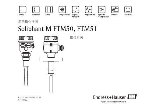
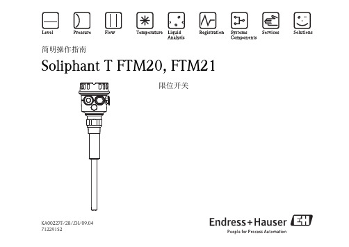
简明操作指南
Soliphant T FTM20, FTM21
限位开关
KA00227F/28/ZH/09.04 71229152
目录
安全指南
3
操作
4
设备标识
6
应用
10
测量系统
11
安装
12
设置
16
指示灯信号
18
电气连接
19
维护
24
技术参数
25
滑动套管
26
故障排除
28
备件
29
补充文档资料
30
"
小心! = 禁止;
90
150 T2*
°C
x °C = (1.8 x + 32) °F
䗷〻䘎᧕䱴Ԧ
pe = max. 25 bar (363 psi) *
പᯉᇶᓖ
䉧㋂བྷሿ
i
min. 200 g/l
5l
1.0
kg
ø max. 25 mm
(max. 1.0 in)
Endress + Hauser
25
滑动套管 常压操作, IP65
Soliphant T FTM20, FTM21
《安全指南》 XA00300F
4 0 II 1/3 D, EEx ia IIC/IIB
30Βιβλιοθήκη Endress + Hauser
KA00227F/28/ZH/09.04, FM10.0
/worldwide
7122916512
导致不正确操作或损坏
2
Endress + Hauser
安全指南 Soliphant T FTM20, FTM21 是一款限 位开关,用于细粒固料和粗糙块料 的限位检测。 使用不当可能会导致应用危险。 仅允许经授权的合格专业人员进行 限位开关的安装、电气连接、调 试、操作和维护,必须严格遵守 《操作手册》、相关标准、法律要求 和证书 ( 取决于实际应用 ) 中的要 求。 在设备附近安装易于操作的电源开 关。 标识电源开关方便设备通断。
Endress + Hauser
2 FEM 22; PN P, 10...45 V DC
4 FEM 24; DPDT , 19...253 V AC / 55 V DC
9 *2
20...23
F16
2 F16, IP66/67; M20
PBT
3 F16, IP66/67; NP T ½
4 F16, IP66/67; G ½
~70 22
SW 60 / 60 AF
SW 60 / 60 AF
R 1½
1½ - 11½ NPT
Endress + Hauser
27
故障排除
故障 开关不动作
开关不正确 间断故障切换
原因 无电源 信号线故障 电子插件故障 固料密度过低
传感器杆硬化 FEM24: 触点焊接在一起 ( 短路后 ) 低限 (MIN) / 高限 (MAX) 设置错误 强射频干扰 (RFI) 强振动
22
FEM24
12 345678
F 0.5 A
NO C NC NO C NC aur aur
L1 N PE (᧕ൠ)
*
*
U~ 19…253 V (AC)
L+ L– U…– 19...55 V (DC)
U~ max. 253 V, I~ max. 6 A P~ max. 1500 VA , cos ϕ = 1
Endress + Hauser
䚥ᆸഭᇦ⌅㿴ʽ
电气连接
FEM …
M 20x1.5
ø 5…9 mm (ø 0.2…0.35 in )
max. 2.5 mm² (max. AWG 14)
max. 4 mm² (max. AWG 12)
3 mm (1/8 in)
Endress + Hauser
19
FEM22 的连接 直流 (DC) 连接 (PNP)
D CSA DIP+FM, DIP
Y 4
A*2TEX II 1/3 D
A DIN 2999 R 1
316L
G DIN 2999 R 1 ½ 316L
M ANSI
NP T 1¼ 316L
N ANSI
NP T 1½ 316L
Y *2
2 FEM22; PN P, 10... 45 V D C
4 FEM24; DPDT , 19...253 V AC/55 V D C
5 F18 , IP66/67; M20
6 F18 , IP66/67; NPT ¾
7 F18 , IP66/67; G ½
F18
9 *2
䬍
A สᵜර
Y *2
*1 ᰐ *2 ަԆ
9
应用 固料中的限位检测
* 防护罩 或 ** 保护管
10
*
**
Endress + Hauser
⭥ᆀᨂԦ
䇒䍗ਧ˖ FTM20 - # # # # #
57. 5
10
M6 (3x)
G 1¼
ø28.17 x 3.53 SW 50 / 50 AF
24.5
R 1½
57.5
24.5
10
M6 (3x)
G 1¼ ø28.17 x 3.53 SW 50 / 50 AF
1½ - 11½ NPT
Endress + Hauser
52023312φR 1 ½ DIN 2999 AISI 316L
A DIN 2999 R 1
316L
G DIN 2999 R 1 ½ 316L
M ANSI
NP T 1¼ 316L
N ANSI
NP T 1½ 316L
Y *2
2 500 mm 3 1000 mm 4 1500 mm 6 20 inch 7 40 inch 8 60 inch 9 *2
Endress + Hauser
28
Endress + Hauser
52025688 (FEM22) 52025691 (FEM24)
备件 电子插件、外壳盖和密封圈
䬍(F18)
EPDM
*
PA (F16) EPDM
* * ֯⭘㜲ᡆ⸣໘⏖━
52005910 52025790
Endress + Hauser
29
补充文档资料
《技术资料》 TI00389F
52025090φ1½ - 11½ NPT ANS I B 1.20.1 AISI 316L
滑动套管 带压操作
M 6x25 SW 5 / 5 AF
ø70
M 6x25 SW 5 / 5 AF
ø70
pe = 25 bar (p e = 360 psi)
max. 150 °C (max. 300 °F)
~70 25
20
FEM22
12 3
(+)
਼ṧ䘲⭘ҾDI⁑ඇ EN 61131-2
F 0.5 A
R –
L+ L– U …– 1 0 V…4 5 V (DC)
R = ཆ䜘䍏䖭
IL Imax. 350 mA Umax. 45 V Endress + Hauser
12 3
FEM22
FEM22 的功能
儎䲆(Max.)
* P~ max. 750 VA , cos ϕ > 0.7 I…– max. 6 A, U…– < 30 V I…– max. 0.2 A, U…– < 125 V
Endress + Hauser
FEM24 12 345678
儎䲆(Max.)
㔯(GN) 哴(YE)
FEM24
345 678
345 678
7 F18, IP66/67; G ½ 9 *2