实验5 图像频域增强
第5章频域图像增强20160801资料.
阶为1
阶为2
阶为5
阶为20
截止频率15下、不同阶巴特沃斯低通滤波器传递函数及其冲激响应函数
9
低通滤波器
截止频率为5
截止频率为15
截止频率为30
截止频率为50
截止频率为90
截止频率为180
不同截止频率下巴特沃斯低通滤波器的滤波结果
10
低通滤波器
– 指数低通滤波器:是一种物理可实现的低通滤波器, n阶指 数低通滤波器的传递函数定义为,
– 带通滤波器:带通滤波器允许某一带宽范围的频率成分通过,而
限制带宽范围以外的频率成分通过。
– 理想带通滤波器具有完全平坦的通带,在通带内没有增益或者衰 减,完全阻止通带之外的所有频率成分,通带与阻带之间的过渡 在瞬时频率完成,其传递函数定义为,
式中,W为带宽,半径 为频带中心,
和
分别
为下限和上限截止频率, 是点 到频谱中心的距离。
12
低通滤波器
截止频率为5
截止频率为15
截止频率为30
截止频率为50
截止频率为90
截止频率为180
不同截止频率指数低通滤波器的滤波结果
13
高通滤波器
高通滤波器:其目的是允许图像的高频成分通过, 而限制低频成分通过。
– 理想低通滤波器:最理想的低通滤波器是完全截断频谱中 的低频成分,传递函数定义为,
通过,并限制高频成分通过;高通滤波是指允许高频成 分通过,并限制低频成分通过。
– 频域滤波表示为频域滤波器的传递函数
频谱
乘积的形式:
与输入图像
– 最后,对频域滤波结果 空域中,可表示为,
进行傅里叶逆变换,转换回
输入图像
f (x;y)
实验五 图像的频域增强

实验五 图像的频域增强一、实验目的1、了解图像滤波的基本定义及目的;2、了解频域滤波的基本原理及方法;3、掌握用MA TLAB 语言进行图像的频域滤波的方法。
二、实验原理1、低通滤波一般来说,图像的边缘和噪声都对应于傅立叶变换中的高频部分,所以能够 让低频信号畅通无阻而同时滤掉高频分量的低通滤波器能够平滑图像,去除噪声.常用的几种有,理想的低通滤波器,巴特沃斯低通滤波器,指数滤波器等.传递函数形式如下所示.理想的低通滤波器:001(,)(,)0(,)D u v D H u v D u v D ≤⎧=⎨>⎩巴特沃斯低通滤波器201(,)1[(,)/]n H u v D u v D =+ 指数滤波器 0[(,)/](,)n D u v D H u v e -=(,)D u v 表示(,)u v 到原点的距离,0D 表示截止频率点到原点的距离。
傅立叶变换的主要能量集中在频谱的中心,合理的选择截止频率对保留图象的能量至关重要。
理想的低通滤波后的图象将会出现一种“振铃”特性,造成图象不同程度的模糊,0D 越小,模糊的程度越明显。
造成这种模糊的原因在于理想的低通滤波器的传递函数在0D 处有1突变为0,经傅立叶反变换后在空域中表现为同心圆的形式。
2、高通滤波与图像中灰度发生骤变的部分与其频谱的高频分量相对应,所以采用高通滤波器衰减或抑制低频分量,是高频分量畅通并对图象进行锐化处理。
常用的高通滤波器有理想的高通滤波器、巴特沃斯高滤波器,指数高通滤波等。
传递函数如下。
理的高通滤波器:001(,)(,)0(,)D u v D H u v D u v D ≥⎧=⎨<⎩巴特沃斯低通滤波器201(,)1[/(,)]nH u v D D u v =+指数滤波器0[/(,)](,)nD D u v H u v e -=由于经过高通滤波后图像丢失了许多低频信息,所以图像平滑区基本会消失。
为此,需要采用高频加强滤波来弥补。
ch5_频域增强

5.1 频域增强原理
陷波滤波器
0, (u, v) ( M / 2, N / 2) H (u, v) 1, 其他
设置F(0,0)=0(结果图像的平均值为零),而保留 其它傅里叶变换的频率成分不变 除了原点处有凹陷外,其它均是常量函数 由于图像平均值为0而产生整体平均灰度级的降低 用于识别由特定的、局部化频域成分引起的空间 图像效果
2 12 2
5.2.1 理想低通滤波
理想低通滤波器的三维透视图、频谱图及径向剖
面图
说明:在半径为D0的圆内,所有频率没有衰减地通过滤波 器,而在此半径的圆之外的所有频率完全被衰减掉
5.2.1 理想低通滤波
ቤተ መጻሕፍቲ ባይዱ想低通滤波器截止频率的设计
先求出总的图像功率谱PT
M 1 N 1
P T
5.1 频域增强原理
5.1 频域增强原理
5.1 频域增强原理
频率域滤波的基本步骤
思想:通过滤波器函数以某种方式来修改图 像变换,然后通过取结果的反变换来获得处 理后的输出图像
5.1 频域增强原理
一些基本的滤波器:如何作用于图像?
陷波滤波器 低通(平滑)滤波器 高通(锐化)滤波器
人脸图像处理
原图像 D0=30的GLPF滤波 D0=10的GLPF滤波
5.3 高通滤波
频域高通滤波的基本思想
G u, v H u, v F u, v
F(u,v)是需要锐化的傅里叶变换形式 目标是选取一个低通滤波器H(u,v),通过它减少
F(u,v)低频部分来得到G(u,v) 运用傅里叶逆变换得到锐化的图像
透视图
滤波器
各种D0值的滤波器横截面
实验五--图像频域变换
实验五图像频域变换一、实验目的1.了解傅里叶变换在图像处理中的应用2.利用Matlab语言编程实现图像的频域变换。
二、实验内容1. 打开并显示一幅图像,对其进行Fourier变换,观察其频谱图像。
2. 用两种方法将图像的频域中心移动到图像中心,然后观察其Fourier变换后的频谱图像。
(见Fourier变换的性质:f(x,y) (-1)x+y F(u-N/2,v-N/2))对图像的Fourier变换频谱进行滤波,如:将频谱超过某个给定的值(均值或2/3均值)的变换值变为0,然后再求其Fourier逆变换,比较所得图像与原图像的差别。
3.对图像进行离散余弦变换,并观察其变换域图像。
要求:用Matlab语言进行编程实现上述功能,同时也应该熟悉用Matlab中现有的函数来实现。
傅里叶变换A)傅里叶变换基本操作I = imread(你的图像);imshow(I);title('源图像');J = fft2(I);figure, imshow(J);title('傅里叶变换');%频移JSh = fftshift(J);figure, imshow(JSh);title('傅里叶变换频移');%直接傅里叶反变换Ji = ifft2(J);figure, imshow(Ji/256);title('直接傅里叶反变换');%幅度JA = abs(J);iJA = ifft2(JA);figure, imshow(iJA/256);title('幅度傅里叶反变换');%相位JP = angle(J);iJP = ifft2(JP);figure, imshow(abs(iJP)*100);title('相位傅里叶反变换');B)利用MATLAB软件实现数字图像傅里叶变换的程序I=imread(‘原图像名.gif’); %读入原图像文件imshow(I); %显示原图像fftI=fft2(I); %二维离散傅里叶变换sfftI=fftshift(fftI); %直流分量移到频谱中心RR=real(sfftI); %取傅里叶变换的实部II=imag(sfftI); %取傅里叶变换的虚部A=sqrt(RR.^2+II.^2);%计算频谱幅值A=(A-min(min(A)))/(max(max(A))-min(min(A)))*225;%归一化figure; %设定窗口imshow(A); %显示原图像的频谱C)绘制一个二值图像矩阵,并将其傅里叶函数可视化。
实验五图像增强

实验五图像增强实验五图像增强⼀、实验⽬的1.了解灰度变换增强和空域滤波增强的Matlab实现⽅法2.掌握直⽅图灰度变换⽅法3.掌握噪声模拟和图像滤波函数的使⽤⽅法4.了解图像复原的Matlab实现⽅法⼆、实验步骤1、打开MATLAB软件,设置⼯作路径,新建M⽂件。
2、将图⽚放到当前⼯作路径下3、写⼊图像增强(包括灰度变换增强、空域滤波增强)程序保存并调试运⾏。
程序具体要求:1)灰度变换增强A)线段上像素灰度分布B)直⽅图变换(直⽅图显⽰、直⽅图灰度调节、直⽅图均衡化)2)空域滤波增强A)噪声模拟B)空域滤波空域滤波对上述噪声图像进⾏均值滤波和中值滤波,⽐较滤波效果。
总结均值滤波和中值滤波的特点及使⽤场合。
*对图像'saturn.tif'采⽤'laplacian'⾼通滤波器进⾏锐化滤波。
4、保存实验结果并完善实验报告。
三、实验程序1.灰度变换增强A)线段上像素灰度分布读⼊灰度图像‘cameraman.tif’,采⽤交互式操作,⽤improfile绘制⼀条线段的灰度值。
imshow('cameraman.tif')improfile读⼊RGB图像‘trees.tif’,显⽰所选线段上红、绿、蓝颜⾊分量的分布imshow('trees.tif')i mprofileB)直⽅图变换直⽅图显⽰读⼊图像‘trees.tif’,在⼀个窗⼝中显⽰灰度级n=64,128和256的图像直⽅图。
I=imread('trees.tif');imshow(I)figure,imhist(I,64)figure,imhist(I,128)figure,imhist(I,256)直⽅图灰度调节利⽤函数imadjust调解图像灰度范围,观察变换后的图像及其直⽅图的变化。
I=imread('trees.tif');imshow(I)figure,imhist(I)J=imadjust(I,[0.15 0.9],[0 1]);figure,imhist(J)figure,imshow(J)I=imread('cameraman.tif');imshow(I)figure,imhist(I)J=imadjust(I,[0 0.2],[0.5 1]);figure,imhist(J)figure,imshow(J)直⽅图均衡化分别对图像‘pout.tif’和‘tire.tif’进⾏直⽅图均衡化处理,⽐较处理前后图像及直⽅图分布的变化。
遥感图像的频率域增强

遥感图象的频率增强与多光谱增强一、实验目的:学习并掌握遥感图象频率域增强的原理与方法,理解频率域增强的意义。
学习和掌握主成分变换,缨帽变换和色彩变换的基本原理与方法,理解三种变换方法处理的效果及意义二、实验内容:频率域平滑频率域锐化主成分变换缨帽变换色彩变换三、实验原理与方法:频率域增强的方法的基本过程:将空间域图象通过傅立叶变换为频率域图象,然后选择合适的滤波器频谱成分进行增强,再经过傅立叶逆变换变回空间域,得到增强后的图象。
K-L变换是离散(Karhunen-Loeve)变换的简称,又被称作主成分变换。
它是对某一多光谱图像X,利用K-L变换矩阵A进行线性组合,而产生一组新的多光谱图像Y,表达式为Y=AX对图像中每一个像元矢量逐个乘以矩阵A,便得到新图像中每一个像元矢量。
A的作用是给多波段的像元亮度加权系数,实现线性变换。
由于变换前各波段之间有很强的相关性,经过K-L变换组合,输出图像Y的各分量yi之间将具有最小的相关性,这就是变换矩阵A 的作用K-T变换是Kauth-Thomas变换的简称,也称缨帽变换。
这种变换也是一种线性组合变换,其变换公式为:Y=BX彩色变换实际上就是根据人眼对色彩的分辨力远远大于对灰度的分辨力,将RGB色彩系统和IHS色彩系统相互转化来提高图像被人眼感知的效果四、实验步骤:(省略)实验原图:傅立叶变换图Butterworth滤波器处理Butterworth 高通滤波器Butterworth 低通滤波器Ideal滤波器Ideal 低通滤波器Ideal 高通滤波器Ideal 低通滤波器处理Ideal 高通滤波器处理Butterworth 高通滤波器处理Butterworth低通滤波器处理实验原图主成分正变换后图像实验原主成分处理后再经逆变换处理后图像实验原图缨帽变换后图像原RGB图像HIS图像五、结果分析和讨论:1.比较滤波处理前后的图像,分析低通滤波和高通滤波处理的效果1)经过高通滤波器处理后的图像,图像被锐化,边缘出现抖动现象,2)经过低通滤波处理后的图像,可以有效的消除噪声,由于高频部分含有大量边缘信息,导致边缘损失,图像边缘模糊。
图像处理与分析-5频域图像增强
W.Q. Wang (SCCE,UCAS)
Image Processing and Analysis
November 10, 2015
1 / 42
Outline
1
2-D Discrete Fourier Transform Filtering in the Frequency Domain Obtaining Frequency Domain Filters from Spatial Filters Generating Filters Directly in the Frequency Domain
f or x = 0, 1, 2, ..., M − 1
Since ejθ = cos θ + j sin θ, then DFT can be redefined as F (u) = − j sin 2πux M ] f or u = 0, 1, 2, ..., M − 1
Frequency (time) domain: the domain (values of u) over which the values of F (u) range; because u determines the frequency of the components of the transform. Frequency (time) component: each of the M terms of F (u).
10 / 42
2-D Discrete Fourier Transform
Properties of 2-D DFT (cont.)
Seperability F (u, v ) = [f (x, y )]
yv = Σy [Σx f (x, y )exp(−j 2π xu M )]exp(−j 2π N )
第5章 图像频域增强

我们人眼能分别得出图像的灰度不仅仅是由于光照函数(照射分量)决定,而且还与 反射函数(反射分量)有关: 反射函数反映出图像的具体内容。光照强度一般具有一致性,在空间上通常会有缓 慢变化的性质,在傅立叶变换下变现为低频分量 然而不一样的材料的反射率差异较大,经常会引起反射光的急剧变化,从而使图像 的灰度值发生变化,这种变化与高低频分量有关。 为了消除不均匀照度的影响,增强图像的高频部分的细节,可以采用建立在频域的 同态滤波器对光照不足或者有光照变化的图像进行处理,可以尽量减少因光照不足 引起的图像质量下降,并对感兴趣的景物进行有效增强,这样就在很大程度上做到 了原图像的图像增强。 同态滤波器能够减少低频并且增加高频,从而能减少光照变化并锐化边缘细节。
频域空间中,图像的信息表现为不同频率分量的组合。通过抑制某些频率分 量的输出,改变频率分布,达到不同的增强目的。 频域空间的增强有三个步骤: step 1:空域 频域 step 2:频域内增强 step 3:频域 空域
卷积定理
去除(抑制)图像中的高频分量而使低频通过,达到平滑和去除噪音 的效果。 (1)理想低通滤波器 截止频率 (5.2.1)
(3)带通和带阻滤波器的联系 两者是互补关系。
带通滤波器 带阻滤波器
陷波滤波器可以阻止或通过以某个频率为中心的邻域里的频率,所以本质上仍然是带 阻或带通滤波器 可分为陷波带阻滤波器和陷波带通滤波器 借助陷波滤波器可以消除周期噪声
理想陷波带阻滤波器
根据Fourier 变换的对称性,为了消除不是以原点为中心的给定区域内的频率,陷波带
第5章-频域图像增强20161028

知识回顾(1)
第3章 空域图像增强
图像平滑:模糊和降噪; 图像锐化:增强图像中的边缘和细节,减弱或清除灰度变 化缓慢的区域。
空域图像增强和频域图像增强结合起来就是图像增强技术的 完整内容。
输入图像
进行傅里叶逆变换,转换回空域中: 表示傅里叶逆变换。
傅里叶逆变换 增强图像
为滤波图像,
F (u; v )
傅里叶变换 滤波函数
H (u; v ) F (u; v )
f (x; y )
H (x; y )
g (x; y )
频域滤波的方框图
9
频域滤波基本步骤
传递函数 为实数的滤波器称为零相位滤波器,不
图像平滑
均值平滑模板 高斯平滑模板
图像锐化
4邻域拉普拉斯 8邻域拉普拉斯
知识回顾(2)
第4章 频域变换
傅里叶变换:频谱是一种在频域中描述图像特征的方法, 反映了图像的幅度和相位随频率的分布情况。
频谱特性:图像的平坦区域对应频谱中的低频成分,而图 像的细节内容对应频谱中的高频成分。
频域图像增强正是利用图像在频域中特有的频率特征进行 滤波处理。
截止频率为15
截止频率为30
理想高通滤波器的传递函数及其冲激响应函数
35
理想高通滤波器
高通滤波器的空域冲激响应函数中心都有一个冲激,这 是因为
式中,
为单位脉冲函数,
表示互为傅里叶变换对。
36
理想高通滤波器
灰度图像
截止频率为5
截止频率为15
傅里叶谱
数字图像处理之频率域图像增强

图像增强技术广泛应用于医学影 像、遥感、安全监控、机器视觉
等领域。
频率域图像增强的概念
01
频率域图像增强是指在频率域 对图像进行操作,通过改变图 像的频率成分来改善图像的质 量。
02
频率域增强方法通常涉及将图 像从空间域转换到频率域,对 频率域中的成分进行操作,然 后再将结果转换回空间域。
直方图规定化
直方图规定化是另一种频率域图像增强 方法,其基本思想是根据特定的需求或 目标,重新定义图像的灰度级分布,以
达到增强图像的目的。
与直方图均衡化不同,直方图规定化可 以根据具体的应用场景和需求,定制不 同的灰度级分布,从而更好地满足特定
的增强需求。
直方图规定化的实现通常需要先对原始 图像进行直方图统计,然后根据规定的 灰度级分布进行像素灰度值的映射和调
灵活性
频率域增强允许用户针对特定频率成 分进行调整,从而实现对图像的精细 控制。例如,可以增强高频细节或降 低噪声。
总结与展望 数字图像处理之频率域图像增强的优缺点
频谱混叠
在频率域增强过程中,如果不采取适 当的措施,可能会导致频谱混叠现象, 影响图像质量。
计算复杂度
虽然频率域增强可以利用FFT加速, 但对于某些复杂的图像处理任务,其 计算复杂度仍然较高。
傅立叶变换具有线性、平移不变性和周期性等性质,这些性质在图像增强中具有重 要应用。
傅立叶变换的性质
线性性质
傅立叶变换具有线性性质,即两 个函数的和或差经过傅立叶变换 后,等于它们各自经过傅立叶变
换后的结果的和或差。
平移不变性
傅立叶变换具有平移不变性,即 一个函数沿x轴平移a个单位后, 其傅立叶变换的结果也相应地沿
THANKS
图像频域增强研究

图像频域增强方法研究一、设计目的1.掌握图像频域增强的概念及其计算方法。
2.熟练掌握傅立叶变换和卷积的计算过程。
3.熟练掌握频域滤波中常用的Butterworth低通滤波器。
4.利用MATLAB程序进行图像增强。
二、设计要求1.熟练掌握MATLAB的运行环境,并能熟练应用。
2.掌握并理解MATLAB的各种编程方式及函数定义。
3.加深对数字图像处理的研究。
三、设计方案1.图像频域增强原理图像增强是指按特定的需要突出一幅图像中的某些信息,同时,消弱或去除某些不需要的信息的处理方法。
其主要目的是处理后的图像对某些特定的应用比原来的图像更加有效。
图像增强的方法分为空域法和频域法两类,空域法主要是对图像中的各个像素点进行操作;而频域法是在图像的某个变换域内,对图像进行操作,修改变换后的系数,例如傅立叶变换、DCT变换等的系数,然后再进行反变换得到处理后的图像。
卷积理论是频域技术的基础。
设函数f(x,y)与线性位不变算子h(x,y)的卷积结果是g(x,y),即g(x,y)=h(x,y)*f(x,y),那么根据卷积定理在频域有:G(u,v)=H(u,v)F(u,v) (1)其中G(u,v),H(u,v),F(u,v)分别是g(x,y),h(x,y),f(x,y)的傅立叶变换。
用线性系统理论的话来说,H(u,v)是转移函数。
在具体的增强应用中,f(x,y)是给定的(所以F(u,v)可利用变换得到),需要确定的是H(u,v),这样具有所需特性的g(x,y)就可由式(1)算出G(u,v)而得到:g(x,y)=F-1[H(u,v)F(u,v)] (2)2.MATLAB简介它的名称源自Matrix Laboratory ,它是一种科学计算软件,专门以矩阵的形式处理数据。
MATLAB 将高性能的数值计算和可视化集成在一起,并提供了大量的内置函数,从而被广泛地应用于科学计算、控制系统、信息处理等领域的分析、仿真和设计工作,而且利用MATLAB 产品的开放式结构,可以非常容易地对MATLAB 的功能进行扩充,从而在不断深化对问题认识的同时,不断完善MATLAB 产品以提高产品自身的竞争能力。
实验5 图像频域增强

试验5 图像频域增强一.试验目的通过本实验使学生掌握使用MATLAB的二维傅里叶变换进行频域增强的方法。
二.试验内容(一)dftuv函数:function [U,V]=dftuv(M,N)u=0:(M-1);v=0:(N-1);idx=find(u>M/2);u(idx)=u(idx)-M;idy=find(v>N/2);u(idy)=v(idy)-N;[V,U]=meshgrid(v,u);低通滤波器函数:function [H,D]=lpfilter(type,M,N,D0,n)[U,V]=dftuv(M,N);D=sqrt(U.^2+V.^2);switch typecase'ideal'H=double(D<=D0);case'btw'if nargin==4n=1;endH=1./(1+(D./D0).^(2*n));case'gaussian'H=exp(-(D.^2)./(2*(D0^2)));otherwiseerror('Unknown filter type')end教材程序:%====================¶ÁÈëÔ-ͼÏñ====================================== lena=imread('d:\test_images\lena_gray_1.tif','tif');figure(1);subplot(1,2,1);imshow(lena);title('origin');size(lena);%===ÁãÑÓÍØ===lena_B=padarray(lena,[512,512],'post');%0 padd fp 2subplot(1,2,2);imshow(lena_B);title('lena_B');%====°áÒÆ====for i=1:1024for j=1:1024lena_B_2(i,j)=(-1).^(i+j).*lena_B(i,j);endendfigure(2);subplot(1,2,1);imshow(lena_B_2);title('banyi');S=abs(fft2(lena_B));%δ°áÒƵÄƵÆ×Fc_lena=fftshift(fft2(lena_B));subplot(1,2,2);imshow(abs(Fc_lena),[]);title('Spectum lena');%4[H1,D1]=lpfilter('gaussian',1024,1024,50,1);F=fft2(lena_B,size(H1,1),size(H1,2));G=real(ifft2(H1.*F));Gf=G(1:size(lena_B,1),1:size(lena_B,2));figure(3);subplot(1,2,1);imshow(uint8(Gf));title('δ²Ã¼ôµÄͼÏñ'); Gf1=G(1:size(lena,1),1:size(lena,2));subplot(1,2,2);imshow(uint8(Gf1));;title('»Ö¸´µÄͼÏñ');origin lenaBbanyi Spectum lena未裁剪的图像恢复的图像(二)频域低通滤波器(白条)f1=zeros(64,64);f1(12:52,24:40)=255;subplot(1,3,1);imshow(f1);title('origin');F1=padarray(f1,[64,64],'post');%==理想滤波器=======H=lpfilter('ideal',128,128,60);F=fft2(F1,size(H,1),size(H,2));G=real(ifft2(H.*F));GF=G(1:size(f1,1),1:size(f1,2));subplot(1,3,2);imshow(GF);title('ideallp');%==巴特沃斯滤波器===========[H1,D1]=lpfilter('btw',128,128,70);F1=fft2(F1,size(H1,1),size(H1,2));G1=real(ifft2(H1.*F1));GF1=G1(1:size(f1,1),1:size(f1,2));subplot(1,3,3);imshow(GF1);title('btwlp');origin ideallp btwlp频域低通滤波器(lena)lena_gray=imread('lena_gray.tif','tif');lena_gauss=imnoise(lena_gray,'gauss',0.03);subplot(1,3,1);imshow(lena_gauss);title('origin');LENA=padarray(lena_gauss,[512,512],'post');%==理想滤波器=========H=lpfilter('ideal',1024,1024,80);F=fft2(LENA,size(H,1),size(H,2));G=real(ifft2(H.*F));GF=G(1:size(lena_gauss,1),1:size(lena_gauss,2));subplot(1,3,2);imshow(uint8(GF));title('ideallp');%==巴特沃斯滤波器=======H1=lpfilter('btw',1024,1024,100);F1=fft2(LENA,size(H1,1),size(H1,2));G1=real(ifft2(H1.*F1));GF1=G1(1:size(lena_gauss,1),1:size(lena_gauss,2));subplot(1,3,3);imshow(uint8(GF1));title('btwlp');origin ideallp btwlp(3)低通滤波器函数:function [H,D]=hpfilter(type,M,N,D0,n)[U,V]=dftuv(M,N);D=sqrt(U.^2+V.^2);switch typecase'ideal'H=double(D>=D0);case'btw'if nargin==4n=1;endH=1-1./(1+(D./D0).^(2*n));case'gaussian'H=1-exp(-(D.^2)./(2*(D0^2)));otherwiseerror('Unknow filter type')end频域低通滤波器(白条)f1=zeros(64,64);f1(12:52,24:40)=255;subplot(1,3,1);imshow(f1);title('origin');F1=padarray(f1,[64,64],'post');%==理想滤波器=========H=hpfilter('ideal',128,128,50);F=fft2(F1,size(H,1),size(H,2));G=real(ifft2(H.*F));GF=G(1:size(f1,1),1:size(f1,2));subplot(1,3,2);imshow(GF);title('ideallp'); %==巴特沃斯滤波器=============[H0,D]=hpfilter('btw',128,128,50);F0=fft2(F1,size(H0,1),size(H0,2));G0=real(ifft2(H0.*F0));GF0=G0(1:size(f1,1),1:size(f1,2));subplot(1,3,3);imshow(GF0);title('btwlp');origin ideallp btwlp频域低通滤波器(lena)lena_gray=imread('lena_gray.tif','tif');lena_gauss=imnoise(lena_gray,'gauss',0.02);subplot(1,3,1);imshow(lena_gauss);title('origin');LENA=padarray(lena_gauss,[512,512],'post');%==H=hpfilter('ideal',1024,1024,150);F=fft2(LENA,size(H,1),size(H,2));G=real(ifft2(H.*F));GF=G(1:size(lena_gauss,1),1:size(lena_gauss,2));subplot(1,3,2);imshow(uint8(GF));title('ideallp');%==H0=hpfilter('btw',1024,1024,50);F0=fft2(LENA,size(H0,1),size(H0,2));G0=real(ifft2(H0.*F0));GF0=G0(1:size(lena_gauss,1),1:size(lena_gauss,2));subplot(1,3,3);imshow(uint8(GF0));title('btwlp');origin ideallp btwlp三.思考理想低通滤波器会产生振铃现象,巴特沃斯不会,但高阶的滤波器会产生振铃;低通滤波器会保留大部分信息,即低频成分,而高通滤波器会滤掉低频成分,剩下图像的大体形状。
实验5 图像频域增强
实验5 图像频域增强一、实验目的通过本实验使学生掌握使用MATLAB的二维傅里叶变换进行频域增强的方法。
二、实验原理本实验是基于数字图像处理课程中的图像频域增强理论来设计的。
本实验的准备知识:第四章频域图像增强中的一维傅里叶变换和二维傅里叶变换,频域图像增强的步骤,频域滤波器。
根据教材285页到320页的内容,开展本实验。
可能用到的函数:1、延拓函数padarray例:A=[1,2;3,4];B=padarray(A,[2,3],’post’);则结果为B =1 2 0 0 03 4 0 0 00 0 0 0 00 0 0 0 0使用该函数实现图像的0延拓。
Padarray还有其它用法,请用help查询。
2、低通滤波器生成函数首先编写dftuv函数,如下function [U,V]=dftuv(M,N)%DFTUV Computes meshgrid frequency matrices.% [U,V]=DFTUV(M,N] computes meshgrid frequency matrices U and V. Uand V are useful for computing frequency-domain filter functions thatcan be used with DFTFILT. U and V are both M-by-N.% Set up range of variables.u=0:(M-1);v=0:(N-1);% Compute the indices for use in meshgrid.idx=find(u>M/2);u(idx)=u(idx)-M;idy=find(v>N/2);v(idy)=v(idy)-N;%Compute the meshgrid arrays.[V,U]=meshgrid(v,u);然后编写低通滤波器函数function [H,D]=lpfilter(type,M,N,D0,n)% LPFILTER computers frequency domain lowpass filters.% H=lpfilter(TYPE,M,N,D0,n) creates the transfer function of a lowpassfilter, H, of the specified TYPE and size(M-by-N). To view the filter asan image or mesh plot, it should be centered using H=fftshift(H).% valid values for TYPE, D0, and n are:% 'ideal' Ideal lowpass filter with cutoff frequency D0. n need notbe supplied. D0 must be positive.% 'btw' Butterworth lowpass filter of ordern, and cutoff D0. Thedefault value for n is 1. D0 must be positive.% 'gaussian' Gaussian lowpass filter with cutoff (standard deviation)D0.n need not be supplied. D0 must be positive.%Use function dftuv to set up the meshgrid arrays needed for computingthe required distances.[U,V]=dftuv(M,N); %D=sqrt(U.^2+V.^2); % Compute the distances D(U,V)% Begin filter computations.switch typecase 'ideal'H=double(D<=D0);case 'btw'if nargin==4n=1;endH=1./(1+(D./D0).^(2*n));case 'gaussian'H=exp(-(D.^2)./(2*(D0^2)));otherwiseerror('Unknown filter type')end通过调用函数lpfilter可生成相应的滤波器掩膜矩阵。
5.图像的频域增强及傅里叶变换
5. 图像的频域增强及傅里叶变换傅立叶变换在图像处理中有非常非常的作用。
因为不仅傅立叶分析涉及图像处理的很多方面,傅立叶的改进算法,比如离散余弦变换,gabor与小波在图像处理中也有重要的分量。
印象中,傅立叶变换在图像处理以下几个话题都有重要作用:1.图像增强与图像去噪绝大部分噪音都是图像的高频分量,通过低通滤波器来滤除高频——噪声; 边缘也是图像的高频分量,可以通过添加高频分量来增强原始图像的边缘;2.图像分割之边缘检测提取图像高频分量3.图像特征提取:形状特征:傅里叶描述子纹理特征:直接通过傅里叶系数来计算纹理特征其他特征:将提取的特征值进行傅里叶变换来使特征具有平移、伸缩、旋转不变性4.图像压缩可以直接通过傅里叶系数来压缩数据;常用的离散余弦变换是傅立叶变换的实变换;傅立叶变换傅里叶变换是将时域信号分解为不同频率的正弦信号或余弦函数叠加之和。
连续情况下要求原始信号在一个周期内满足绝对可积条件。
离散情况下,傅里叶变换一定存在。
冈萨雷斯版<图像处理>里面的解释非常形象:一个恰当的比喻是将傅里叶变换比作一个玻璃棱镜。
棱镜是可以将光分解为不同颜色的物理仪器,每个成分的颜色由波长(或频率)来决定。
傅里叶变换可以看作是数学上的棱镜,将函数基于频率分解为不同的成分。
当我们考虑光时,讨论它的光谱或频率谱。
同样,傅立叶变换使我们能通过频率成分来分析一个函数。
傅立叶变换有很多优良的性质。
比如线性,对称性(可以用在计算信号的傅里叶变换里面);时移性:函数在时域中的时移,对应于其在频率域中附加产生的相移,而幅度频谱则保持不变;频移性:函数在时域中乘以,可以使整个频谱搬移w。
这个也叫调制定理,通讯里面信号的频分复用需要用到这个特性(将不同的信号调制到不同的频段上同时传输);卷积定理:时域卷积等于频域乘积;时域乘积等于频域卷积(附加一个系数)。
(图像处理里面这个是个重点)信号在频率域的表现在频域中,频率越大说明原始信号变化速度越快;频率越小说明原始信号越平缓。
5频域增强技术

频域图像增强-滤波应用举例
打印、传真、复印、扫描过程会造成字符失真或断裂 等,采用D0=80的高斯低通滤波器修复字符
频域图像增强-滤波应用举例
分别采用D0=100和80的GLPF滤波来减少眼部鱼尾纹
频域图像增强-滤波应用举例
分别采用D0=30和10的GLPF滤波来模糊细节,同时保 留区域的特征,便于计算机分析和识别
频域图像增强-噪声去除
噪声去除:从被噪声污染的图像恢复原图像 g ( x, y ) = f ( x, y ) + η ( x , y )
G (u, v) = F (u, v) + N (u , v)
噪声来源
图像获取的数字化过程,如图像传感器的质量和环 境条件 图像传输过程中传输信道的噪声干扰,如通过无线 网络传输的图像会受到光或其它大气因素的干扰
D0为截至频率距原点的距离,D(u,v)是点(u,v)距原 点的距离 不同于ILPF,BLPF滤波函数没有明显的截断,但随 着D(u,v)的增大,H(u,v)越来越小 当D(u,v)=0时,H(u,v)取最大值1 当D(u,v)=D0时,H(u,v)=0.5
频域图像增强-巴特沃思低通滤波器
要点:阶数n越高,越接近理想低通滤波器
频域图像增强-理想低通滤波器
理想低通滤波器(ILPF)
截断傅里叶变换中的所有高频成分,这些高 频成分处于指定距离D0之外
频率矩形的中心在(u,v)=(M/2,N/2),从点(u,v) 到中心(原点)的距离定义如下:
频域图像增强-理想低通滤波器
要点:截断频率距离D0的选择决定滤波的效果
频域图像增强-理想低通滤波器
n阶BHPF:H (u , v) =
1 1 + [ D0 / D(u , v)]2 n
7.图像增强—频域滤波 - 数字图像处理实验报告
计算机与信息工程学院验证性实验报告一、实验目的1.掌握怎样利用傅立叶变换进行频域滤波 2.掌握频域滤波的概念及方法 3.熟练掌握频域空间的各类滤波器 4.利用MATLAB 程序进行频域滤波二、实验原理及知识点频域滤波分为低通滤波和高通滤波两类,对应的滤波器分别为低通滤波器和高通滤波器。
频域低通过滤的基本思想:G (u,v )=F (u,v )H (u,v )F (u,v )是需要钝化图像的傅立叶变换形式,H (u,v )是选取的一个低通过滤器变换函数,G (u,v )是通过H (u,v )减少F (u,v )的高频部分来得到的结果,运用傅立叶逆变换得到钝化后的图像。
理想地通滤波器(ILPF)具有传递函数:01(,)(,)0(,)ifD u v D H u v ifD u v D ≤⎧=⎨>⎩其中,0D 为指定的非负数,(,)D u v 为(u,v )到滤波器的中心的距离。
0(,)D u v D =的点的轨迹为一个圆。
n 阶巴特沃兹低通滤波器(BLPF)(在距离原点0D 处出现截至频率)的传递函数为201(,)1[(,)]nH u v D u v D =+与理想地通滤波器不同的是,巴特沃兹率通滤波器的传递函数并不是在0D 处突然不连续。
高斯低通滤波器(GLPF)的传递函数为222),(),(σv u D ev u H =其中,σ为标准差。
相应的高通滤波器也包括:理想高通滤波器、n 阶巴特沃兹高通滤波器、高斯高通滤波器。
给定一个低通滤波器的传递函数(,)lp H u v ,通过使用如下的简单关系,可以获得相应高通滤波器的传递函数:1(,)hp lp H H u v =-利用MATLAB 实现频域滤波的程序f=imread('room.tif');F=fft2(f); %对图像进行傅立叶变换%对变换后图像进行队数变化,并对其坐标平移,使其中心化 S=fftshift(log(1+abs(F)));S=gscale(S); %将频谱图像标度在0-256的范围内 imshow(S) %显示频谱图像h=fspecial('sobel'); %产生空间‘sobel’模版 freqz2(h) %查看相应频域滤波器的图像 PQ=paddedsize(size(f)); %产生滤波时所需大小的矩阵 H=freqz2(h,PQ(1),PQ(2)); %产生频域中的‘sobel’滤波器H1=ifftshift(H); %重排数据序列,使得原点位于频率矩阵的左上角 imshow(abs(H),[]) %以图形形式显示滤波器 figure,imshow(abs(H1),[])gs=imfilter(double(f),h); %用模版h 进行空域滤波gf=dftfilt(f,H1); %用滤波器对图像进行频域滤波 figure,imshow(gs,[]) figure,imshow(gf,[])figure,imshow(abs(gs),[]) figure,imshow(abs(gf),[])f=imread('number.tif'); %读取图片PQ=paddedsize(size(f)); %产生滤波时所需大小的矩阵 D0=0.05*PQ(1); %设定高斯高通滤波器的阈值H=hpfilter('gaussian',PQ(1),PQ(2),D0); %产生高斯高通滤波器 g=dftfilt(f,H); %对图像进行滤波 figure,imshow(f) %显示原图像figure,imshow(g,[]) %显示滤波后图像三、实验步骤:1.调入并显示所需的图片;2.利用MATLAB 提供的低通滤波器实现图像信号的滤波运算,并与空间滤波进行比较。
频域增强(图像平滑)
exp{ 0 . 347 [ D ( u , v ) D 0 ] }
D(u,v)=D0,H(u,v)降为最大值的 n为阶数。
1 2
。
3阶指数形低通滤波器转移函数剖面图
(4)梯形低通滤波器
1 H ( u , v ) [ D ( u , v ) D 1 ] ( D 0 D 1 ) 0 D (u , v ) D 0 D 0 D (u , v ) D1 D (u , v ) D1
(2)巴特沃思低通滤波器
H (u , v ) 1 1 ( 2 1)[ D ( u , v ) D 0 ] 1 1 0 . 414 [ D ( u , v ) D 0 ]
1 2
2n
2n
D(u,v)=D0,H(u,v)降为最大值的 n为阶数。
。
(3)指数形低通滤波器
H ( u , v ) exp{[ln( 1 2 )][ D ( u , v ) D 0 ] }
4.4.2 低通滤波法
低通滤波法: 滤除高频成分,保留低频成分,在频域中实 现平滑处理。 滤波公式: G ( u , v ) H ( u , v ) F ( u , v ) F(u,v) 原始图象频谱, G(u,v) 平滑图象频谱, H(u,v) 转移函数。
空间域与频率域
傅氏光谱图像 中间高频,四周低频
4.4
频域增强
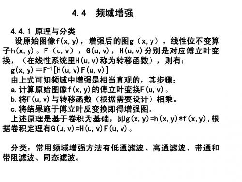
4.4.1 原理与分类 设原始图像f(x,y),增强后的图g(x,y),线性位不变算 子h(x,y)。F(u,v),G(u,v),H(u,v)分别是对应傅立叶变 换,(在线性系统里H(u,v)称为转移函数),则有: g(x,y)=F-1[H(u,v)F(u,v)] 由上式可知频域中增强是相当直观的,其步骤: a.计算原始图像f(x,y)的傅立叶变换F(u,v)。 b.将F(u,v)与转移函数(根据需要设计)相乘。 c.将结果施于傅立叶反变换即得增强图。 上述原理是基于卷积为基础,即g(x,y)=h(x,y)*f(x,y),根 据卷积定理有G(u,v)=H(u,v)F(u,v)。 分类:常用频域增强方法有低通滤波、高通滤波、带通和 带阻滤波、同态滤波。
基于matlab软件的图像频率域增强实验
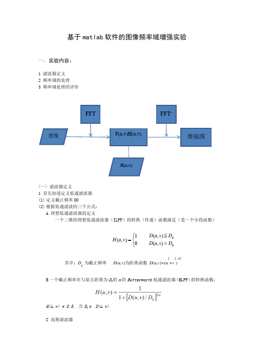
基于matlab 软件的图像频率域增强实验一.实验内容:1 滤波器定义2 频率域的处理3 频率域处理的评价<一> 滤波器定义1 首先知道定义低通滤波器(1) 定义截止频率D0(2) 根据低通滤波的三个公式:A 理想低通滤波器的定义一个二维的理想低通滤波器(ILPF )的转换(传递)函数满足(是一个分段函数)B 一个截止频率在与原点距离为D 0的n 阶Butterworth 低通滤波器(BLPF )的转换函数:H(u,v) = 0.5, 当 D 0 = D(u,v)C 高斯滤波器 FFT图像 F(u,v)H(u,v) H(u,v)FFT -增强图⎩⎨⎧>≤=0),(0),(1),(D v u D D v uD v u H 其中:D 0 为截止频率 D(u,v)为距离函数 D(u,v)=(u 2+v 2)1/22 能够用定义的滤波器与频率图像计算1) 图像傅立叶变换F=fft2(I);F=fftshift(F);2) 图像与滤波器点击G(u,v)=F(u,v)H(u,v)3) 图像反傅立叶变换G=ifftshift(G);g=abs(ifft2(G));二.实验目的:利用matlab 软件对图像进行处理,要求利用傅里叶变换函数fft2进行对图像的傅里叶变换,利用频谱中心化函数fftshift 对图像进行频谱中心化操作,最后检查保存处理后的图像。
三.实验步骤:1.打开matlab 软件,读取目标图像2.利用函数fft2对图像进行傅里叶变换操作3.利用函数fftshift 对图像进行频谱中心化处理4.检查并保存处理后图像四.实验结果:1/222(,)22M N D u v u v ⎡⎤⎛⎫⎛⎫=-+-⎢⎥ ⎪ ⎪⎝⎭⎝⎭⎢⎥⎣⎦五.实验心得:通过本次实验,学习了matlab软件对图像进行频率域增强处理时的基本功能和函数指令操作,让我认识到matlab软件功能的强大,以及自己在研究软件处理图像时的不足,对傅里叶变换和频谱中心操作时函数指令的认识和理解不够透彻。
- 1、下载文档前请自行甄别文档内容的完整性,平台不提供额外的编辑、内容补充、找答案等附加服务。
- 2、"仅部分预览"的文档,不可在线预览部分如存在完整性等问题,可反馈申请退款(可完整预览的文档不适用该条件!)。
- 3、如文档侵犯您的权益,请联系客服反馈,我们会尽快为您处理(人工客服工作时间:9:00-18:30)。
实验5 图像频域增强一、实验目的通过本实验使学生掌握使用MATLAB的二维傅里叶变换进行频域增强的方法。
二、实验原理本实验是基于数字图像处理课程中的图像频域增强理论来设计的。
本实验的准备知识:第四章频域图像增强中的一维傅里叶变换和二维傅里叶变换,频域图像增强的步骤,频域滤波器。
根据教材285页到320页的内容,开展本实验。
可能用到的函数:1、延拓函数 padarray例:A=[1,2;3,4];B=padarray(A,[2,3],’post’);则结果为B =1 2 0 0 03 4 0 0 00 0 0 0 00 0 0 0 0使用该函数实现图像的0延拓。
Padarray还有其它用法,请用help查询。
2、低通滤波器生成函数首先编写dftuv函数,如下function [U,V]=dftuv(M,N)%DFTUV Computes meshgrid frequency matrices.% [U,V]=DFTUV(M,N] computes meshgrid frequency matrices U and V. Uand V are useful for computing frequency-domain filter functions thatcan be used with DFTFILT. U and V are both M-by-N.% Set up range of variables.u=0:(M-1);v=0:(N-1);% Compute the indices for use in meshgrid.idx=find(u>M/2);u(idx)=u(idx)-M;idy=find(v>N/2);v(idy)=v(idy)-N;%Compute the meshgrid arrays.[V,U]=meshgrid(v,u);然后编写低通滤波器函数function [H,D]=lpfilter(type,M,N,D0,n)% LPFILTER computers frequency domain lowpass filters.% H=lpfilter(TYPE,M,N,D0,n) creates the transfer function of a lowpassfilter, H, of the specified TYPE and size(M-by-N). To view the filter as an image or mesh plot, it should be centered using H=fftshift(H).% valid values for TYPE, D0, and n are:% 'ideal' Ideal lowpass filter with cutoff frequency D0. n need not be supplied. D0 must be positive.% 'btw' Butterworth lowpass filter of ordern, and cutoff D0. The default value for n is 1. D0 must be positive.% 'gaussian' Gaussian lowpass filter with cutoff (standard deviation)D0.n need not be supplied. D0 must be positive.%Use function dftuv to set up the meshgrid arrays needed for computing the required distances.[U,V]=dftuv(M,N); %D=sqrt(U.^2+V.^2); % Compute the distances D(U,V)% Begin filter computations.switch typecase 'ideal'H=double(D<=D0);case 'btw'if nargin==4n=1;endH=1./(1+(D./D0).^(2*n));case 'gaussian'H=exp(-(D.^2)./(2*(D0^2)));otherwiseerror('Unknown filter type')end通过调用函数lpfilter可生成相应的滤波器掩膜矩阵。
参考该函数可相应的生成高通滤波器函数。
3、频域滤波F=fft2(f,size(H,1),size(H,2)); % 对延拓的 f 计算 FFT。
注意,这里隐含着对 f 的延拓。
G=real(ifft2(H.*F)); % 滤波Gf=G(1:size(f,1),1:size(f,2)); %裁剪后的图像三、实验内容(一)图像频域增强的步骤参考教材286页的Figure 4.36,重复该图像中的步骤,并将相应的结果显示出来。
(二)频域低通滤波产生实验四中的白条图像。
设计不同截止频率的理想低通滤波器、Butterworth低通滤波器,对其进行频域增强。
观察频域滤波效果,并解释之。
设计不同截止频率的理想低通滤波器、Butterworth低通滤波器,对含高斯噪声的lena 图像进行频域增强。
观察频域滤波效果,并解释之。
(三)频域高通滤波设计不同截止频率的理想高通滤波器、Butterworth高通滤波器,对上述白条图像进行频域增强。
观察频域滤波效果,并解释之。
设计不同截止频率的理想高通滤波器、Butterworth高通滤波器,对含高斯噪声的lena 图像进行频域增强。
观察频域滤波效果,并解释之。
四、实验步骤(二)频域低通滤波理想低通滤波器1. D0=5程序:A=zeros(64,64);A(32-20:32+20,32-8:32+8)=255;subplot(1,2,1)imshow(A);s=fftshift(fft2(A));[M,N]=size(s);n1=floor(M/2); %对M/2进行取整n2=floor(N/2);d0=5;for i=1:Mfor j=1:Nd=sqrt((i-n1)^2+(j-n2)^2); %点(i,j)到傅立叶变换中心的距离h=1*exp(-1/2*(d^2/d0^2)); %GLPF滤波函数s(i,j)=h*s(i,j); %GLPF滤波后的频域表示endends=ifftshift(s);s=uint8(real(ifft2(s)));subplot(1,2,2); %创建图形图像对象imshow(s);运行结果:2.D0=50程序:A=zeros(64,64);A(32-20:32+20,32-8:32+8)=255;subplot(1,2,1)imshow(A);s=fftshift(fft2(A));[M,N]=size(s);n1=floor(M/2); %对M/2进行取整n2=floor(N/2);d0=50;for i=1:Mfor j=1:Nd=sqrt((i-n1)^2+(j-n2)^2); %点(i,j)到傅立叶变换中心的距离h=1*exp(-1/2*(d^2/d0^2)); %GLPF滤波函数s(i,j)=h*s(i,j); %GLPF滤波后的频域表示endends=ifftshift(s);s=uint8(real(ifft2(s)));subplot(1,2,2); %创建图形图像对象imshow(s);运行结果:Butterworth 低通滤波器1.程序A=zeros(64,64);A(32-20:32+20,32-8:32+8)=255;subplot(1,2,1)imshow(A);s=fftshift(fft2(A));[M,N]=size(s);n1=floor(M/2); %对M/2进行取整n2=floor(N/2);d0=5;for i=1:Mfor j=1:Nd=sqrt((i-n1)^2+(j-n2)^2); %点(i,j)到傅立叶变换中心的距离h=1/(1+0.414*(d/d0)^(2*n));s(i,j)=h*s(i,j); %GLPF滤波后的频域表示 endends=ifftshift(s);s=uint8(real(ifft2(s)));subplot(1,2,2); %创建图形图像对象imshow(s);运行结果:含高斯噪声的lena图像进行频域增强clear all;A=imread('D:\pic\lena.bmp')subplot(2,3,1),imshow(A,[]);title('原图') %把图像显示出来B=imnoise(A,'gauss',0.02)subplot(2,3,3),imshow(B,[]); %添加高斯噪声后的图像title('添加高斯噪声后的图像')f=double(B); %图像存储类型转换g=fft2(f); %傅立叶变换g=fftshift(g); %转换数据矩阵[N1,N2]=size(g); %测量图像尺寸参数n=2;d0=50;n1=fix(N1/2);n2=fix(N2/2);for i=1:N1for j=1:N2d=sqrt((i-n1)^+(j-n2)^2)c=double(d<=d0); %result(i,j)=c*g(i,j);endendresul=ifftshift(result); %傅立叶逆变换X2=ifft2(result);X3=uint8(real(X2));subplot(2,3,5)imshow(X3) %显示频域增强后的图像D0=20,butterworth 滤波器D0=50,低通滤波器D0=50,butterworth 滤波器title('D0=50,低通滤波器')运行结果:原图添加高斯噪声后的图像D0=20,低通滤波器(三)频域高通滤波理想高通滤波器 A=zeros(64,64);A(32-20:32+20,32-8:32+8)=255;subplot(1,2,1);imshow(A);s=fftshift(fft2(A));[M,N]=size(s);n1=floor(M/2);%对M/2进行取整n2=floor(N/2);d0=5;for i=1:Mfor j=1:Nd=sqrt((i-n1)^2+(j-n2)^2); %点(i,j)到傅立叶变换中心的距离h=1-(1*exp(-1/2*(d^2/d0^2)));s(i,j)=h*s(i,j); %GLPF滤波后的频域表示endends=ifftshift(s);s=uint8(real(ifft2(s)));subplot(1,2,2); %创建图形图像对象imshow(s);Butterworth 高通滤波器A=zeros(64,64);A(32-20:32+20,32-8:32+8)=255;subplot(1,2,1);imshow(A);s=fftshift(fft2(A));[M,N]=size(s);n1=floor(M/2); %对M/2进行取整n2=floor(N/2);d0=5;for i=1:Mfor j=1:Nd=sqrt((i-n1)^2+(j-n2)^2); %点(i,j)到傅立叶变换中心的距离h=1-(1/(1+0.414*(d/d0)^(2*n)));s(i,j)=h*s(i,j); %GLPF滤波后的频域表示endends=ifftshift(s);s=uint8(real(ifft2(s)));subplot(1,2,2); %创建图形图像对象imshow(s);对含高斯噪声的lena图像理想高通滤波器A1= imread('D:\pic\lena.bmp')A=imnoise(A1, 'gauss', 0.02);subplot(1,2,1);imshow(A);s=fftshift(fft2(A));[M,N]=size(s);n1=floor(M/2); %对M/2进行取整n2=floor(N/2);d0=5;for i=1:Mfor j=1:Nd=sqrt((i-n1)^2+(j-n2)^2); %点(i,j)到傅立叶变换中心的距离h=1-(1*exp(-1/2*(d^2/d0^2)));s(i,j)=h*s(i,j); %GLPF滤波后的频域表示endends=ifftshift(s);s=uint8(real(ifft2(s)));subplot(1,2,2); %创建图形图像对象imshow(s);运行结果:Butterworth 高通滤波器A1= imread('D:\pic\lena.bmp')A=imnoise(A1, 'gauss', 0.02);subplot(1,2,1)imshow(A);s=fftshift(fft2(A));[M,N]=size(s);n1=floor(M/2); %对M/2进行取整n2=floor(N/2);d0=5;for i=1:Mfor j=1:Nd=sqrt((i-n1)^2+(j-n2)^2); %点(i,j)到傅立叶变换中心的距离h=1-(1/(1+0.414*(d/d0)^(2*n)));s(i,j)=h*s(i,j); %GLPF滤波后的频域表示endends=ifftshift(s);s=uint8(real(ifft2(s)));subplot(1,2,2); %创建图形图像对象imshow(s);五、实验心得通过MATLAB软件实现了原理程序及仿真图像。
