切割机网格刻线机中英文对照外文翻译文献
机床行业常用英文对照

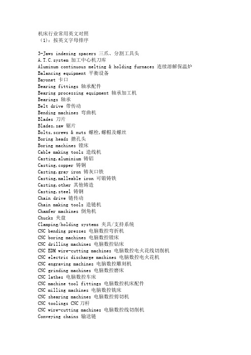
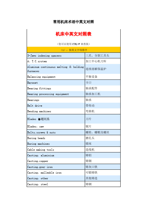
机床行业常用英文对照 3-Jaws indexing spacers 三爪、分割工具头 A.T.C.system 加工中心机刀库A luminum continuous melting & holding furnaces 连续溶解保温炉 Balancing equipment 平衡设备Bayonet 卡口Bearing fittings 轴承配件Bearing processing equipment 轴承加工机Bearings 轴承Belt drive 带传动Bending machines 弯曲机Blades 刀片Blades,saw 锯片Bolts,screws & nuts 螺栓 ,螺帽及螺丝Boring heads 搪孔头Boring machines 镗床Cable making tools 造线机 Casting,aluminium 铸铝Casting,copper 铸铜 Casting,gray iron 铸灰口铁Casting,malleable iron 可锻铸铁 Casting,other 其他铸造Casting,steel 铸钢Chain drive 链传动Chain making tools 造链机Chamfer machines 倒角机Chucks 夹盘Clamping/holding systems 夹具/支持系统 CNC bending presses 电脑数控弯折机 CNC boring machines 电脑数控镗床CNC drilling machines 电脑数控钻床 CNC EDM wire-cutting machines 电脑数控电火花线切削机 CNC electric discharge machines 电脑数控电火花机 CNC engraving machines 电脑数控雕刻机 CNC grinding machines 电脑数控磨床CNC lathes 电脑数控车床CNC machine tool fittings 电脑数控机床配件CNC milling machines 电脑数控铣床CNC shearing machines 电脑数控剪切机CNC toolings CNC 刀杆CNC wire-cutting machines 电脑数控线切削机 Conveying chains 输送链Coolers 冷却机Coupling 联轴器Crimping tools 卷边工具Cutters 刀具Cutting-off machines 切断机Diamond cutters 钻石刀具 Dicing saws 晶圆切割机 Die casting dies 压铸冲模 Die casting machines 压铸机 Dies-progressive 连续冲模 Disposable toolholder bits 舍弃式刀头 Drawing machines 拔丝机 Drilling machines 钻床 Drilling machines bench 钻床工作台 Drilling machines,high-speed 高速钻床 Drilling machines,multi-spindle 多轴钻床 Drilling machines,radial 摇臂钻床 Drilling machines,vertical 立式钻床 drills 钻头Electric discharge machines(EDM) 电火花机 Electric power tools 电动刀具Engraving machines 雕刻机Engraving machines,laser 激光雕刻机 Etching machines 蚀刻机Finishing machines 修整机Fixture 夹具 Forging dies 锻模 Forging,aluminium 锻铝 Forging,cold 冷锻Forging,copper 铜锻 Forging,other 其他锻造 Forging,steel 钢锻 Foundry equipment 铸造设备 Gear cutting machines 齿轮切削机 Gears 齿轮Gravity casting machines 重力铸造机 Grinder bench 磨床工作台Grinders,thread 螺纹磨床 Grinders,tools & cutters 工具磨床Grinders,ultrasonic 超声波打磨机 Grinding machines 磨床 Grinding machines,centerless 无心磨床 Grinding machines,cylindrical 外圆磨床Grinding machines,universal 万能磨床 Grinding tools 磨削工具Grinding wheels 磨轮Hand tools 手工具Hard/soft and free expansion sheet making plant 硬(软)板(片)材及自由发泡板机组 Heat preserving furnaces 保温炉Heating treatment funaces 熔热处理炉Honing machines 搪磨机Hydraulic components 液压元件Hydraulic power tools 液压工具Hydraulic power units 液压动力元件Hydraulic rotary cylinders 液压回转缸Jigs 钻模Lapping machines 精研机Lapping machines,centerless 无心精研机Laser cutting 激光切割Laser cutting for SMT stensil 激光钢板切割机Lathe bench 车床工作台Lathes,automatic 自动车床Lathes,heavy-duty 重型车床Lathes,high-speed 高速车床Lathes,turret 六角车床Lathes,vertical 立式车床Lubricants 润滑液Lubrication Systems 润滑系统Lubricators 注油机Machining centers,general 通用加工中心Machining centers,horizontal 卧式加工中心Machining centers,horizontal & vertical 卧式及立式加工中心Machining centers,vertical 立式加工中心Machining centers,vertical double-column type 立式双柱加工中心Magnetic tools 磁性工具Manifolds 集合管Milling heads 铣头Milling machines 铣床Milling machines,bed type 床身式铣床Milling machines,duplicating 仿形铣床Milling machines,horizontal 卧式铣床Milling machines,turret vertical 六角立式铣床Milling machines,universal 万能铣床Milling machines,vertical 立式铣床Milling machines,vertical & horizontal 立式及卧式铣床Mold & die components 模具单元Mold changing systems 换模系统Mold core 模芯Mold heaters/chillers 模具加热器 /冷却器Mold polishing/texturing 模具打磨 /磨纹Mold repair 模具维修Molds 模具Nail making machines 造钉机Oil coolers 油冷却器Overflow cutting machines for aluminium wheels 铝轮冒口切断机 P type PVC waterproof rolled sheet making plant P 型 PVC 高分子防水 PCB fine piecing systems 印刷电器板油压冲孔脱料系统Pipe & tube making machines 管筒制造机Planing machines 刨床Planing machines vertical 立式刨床Pneumatic hydraulic clamps 气油压虎钳Pneumatic power tools 气动工具Powder metallurgic forming machines 粉末冶金成型机Presses,coldforging 冷锻冲压机 presses,crank 曲柄压力机Presses,eccentric 离心压力机Presses,forging 锻压机Presses,hydraulic 液压冲床Presses,knuckle joint 肘杆式压力机Presses,pneumatic 气动冲床Presses,servo 伺服冲床Presses,transfer 自动压力机Pressing dies 压模Punch formers 冲子研磨器Quick die change systems 速换模系统Quick mold change systems 快速换模系统Reverberatory furnaces 反射炉Rollers 滚筒Rolling machines 辗压机Rotary tables 转台Sawing machines 锯床Sawing machines,band 带锯床Saws,band 带锯Saws,hack 弓锯Saws,horizontal band 卧式带锯Saws,vertical band 立式带锯shafts 轴Shapers 牛头刨床Shearing machines 剪切机Sheet metal forming machines 金属板成型机Sheet metal working machines 金属板加工机Slotting machines 插床 spindles 主轴Stamping parts 冲压机 Straightening machines 矫直机 Switches & buttons 开关及按钮 Tapping machines 攻螺丝机 Transmitted chains 传动链 Tube bending machines 弯管机 Vertical hydraulic broaching machine 立式油压拉床 Vises 虎钳Vises,tool-maker 精密平口钳 Wheel dressers 砂轮修整器 Woven-Cutting machines 织麦激光切割机 Wrenches 扳手(2):按中文拼音字母排序铝轮冒口切断机 Overflow cutting machines for aluminium wheels 离心压力机Presses,eccentric六角立式铣床 Milling machines,turret vertical 六角车床 Lathes,turret 螺栓 ,螺帽及螺丝 Bolts,screws & nuts 螺纹磨床 Grinders,thread 冷却机Coolers 冷锻 Forging,cold 冷锻冲压机 Presses,cold forging 立式双柱加工中心 Machining centers,vertical double-column type 立式铣床 Milling machines,vertical立式油压拉床 Vertical hydraulic broaching machine 立式刨床 Planing machines vertical 立式车床 Lathes,vertical 立式带锯 Saws,vertical band 立式加工中心 Machining centers,vertical 立式及卧式铣床 Milling machines,vertical & horizontal 立式钻床 Drilling machines,vertical 联轴器 Coupling连续溶解保温炉 Aluminum continuous melting & holding furnaces 连续冲模Dies-progressive 链传动 Chain drive 切断机 Cutting-off machinesCNC 刀杆 CNC toolings 曲柄压力机 presses,crank 修整机 Finishing machines舍弃式刀头 Disposable toolholder bits 润滑系统 Lubrication Systems 润滑液 Lubricantssjedeqs谢両诫步 sauiqoeiu 6uiue|d 当両 ]UE|d 6ui>|eiujaai|s pa||OJ joojdjajeM QAd eclA; d *厨£岳豊 OAd fgd sjapui|Ao A JBJOJ oi|riRipAH 珂鋪回刃邈 S|ooi」OMod sinejpAn 菅工刃邈SJIU n」a/v\od oiinejpAn 劫MH匝刃邈Gin ejpAq'sassajd 谢诚刃邈 sjuauodiuoo sinejpAn 秋圧刃邈 sauiqoeiu bu川03 刑刃曙 ]UE|d bupiEiu 记eqs uojsuedxa 334 pue yos/pjen 甲目区斡(畀)您(询)亜lejpej'saumoeiii 6u!i|ua 谢玛昌樹 smajsAs 6u!O8!daujj ggd 腸劉飙!联诚ET耿您兽用侧由 saujqoeujbup|EUJ HBN刑為磽SQOI bupiEiu aiqeg 刑需磽 S|00]bupiEiii ujeqo MH熹 sjeiooo no兽嘩叙耿 sauiqoeiu6unseo aiQ 刑鹊刃 syp 6URSBO Q\Q渤诚鹊ET saip6uissajd 渤刃 ssaijajuao'sauiqoeiu Buidden 刑抱耿q工ssaijajuao'sauiqoeiu 6uipuu9 谢曇Q工 sauiiioeiu6ui||!i/\| 谢菊 speaq 6u!ini/\| 诫菊」eddobbuQjOT 鶴酣 lejauaB'sjajuao 6uiu!qoe|/\| <?申工凹宙爵sauiiioeiu 6uipuaq oqn丄刑易昱 sauiqoeiu 6uipuag 刑聊昱 sauiqoeiu 6uuog 当舅 IBSJ8AIun'sauiqoeiu 6uipuu9谢黑臨 IBSJ8AIun'sauiqoeiu 6ui||!i/\| 当粉曲 |EO屮"$ lejuozuoq'sjajuao 6u!U!qoe|/\| Q出工凹爭军区爭咄lejuozuoii'sjajuao 6uiu!i|oe|/\| q出工凹爭咄pueq lejuozuoq'SMes 酣卑旧目lejuozuoii'sauiiioeiu 6ui||!i/\| 谢菊爭咄 speeq 6uuog 灯聊 sauiiioeiu6UIUOH Ml[團 leoupuiiAo'sauiqoeiu6uipuu9 当曇囿场 sauiiioeiu bqip口刑隆舸 sjdssdjp leaqM HBWWS|001 puen菅工圭 suieqo 6uiAaAuog 列买酚 OAjas'sassajd 当诚齟回 sjaoeds6uixapu! SMep-g 诫菅工[1 曇岳 '汕三saoeunj juaiujeaj; 6uneaH 出if®请物其他铸造 Casting,other 其他锻造Forging,other 模芯 Mold core 模具 Molds 模具维修 Mold repair 模具打磨 /磨纹 Mold polishing/texturing 模具单元 Mold & die components 模具加热器/冷却器 Mold heaters/chillers 磨轮 Grinding wheels 磨削工具 Grinding tools 磨床 Grinding machines 磨床工作台 Grinder bench 平衡设备 Balancing equipment 气油压虎钳 Pneumatic hydraulic clamps 气动冲床Presses,pneumatic 气动工具 Pneumatic power tools 轴 shafts 轴承 Bearings 轴承配件 Bearing fittings 轴承加工机 Bearing processing equipment 肘杆式压力机 Presses,knuckle joint 铸铝 Casting,aluminium 铸铜 Casting,copper 铸造设备 Foundry equipment 铸钢 Casting,steel 铸灰口铁 Casting,gray iron织麦激光切割机 Woven-Cutting machines 重力铸造机 Gravity casting machines 重型车床 Lathes,heavy-duty 主轴 spindles 扳手 Wrenches 拔丝机Drawing machines 保温炉 Heat preserving furnaces 插床 Slotting machines 齿轮 Gears 齿轮切削机 Gear cutting machines 冲压机 Stamping parts 冲子研磨器 Punch formers 超声波打磨机 Grinders,ultrasonic 车床工作台 Lathe bench 磁性工具 Magnetic tools 传动链 Transmitted chains 床身式铣床Milling machines,bed type 带传动 Belt drive带锯 Saws,band 带锯床 Sawing machines,band 电脑数控镗床 CNC boring machines 电脑数控弯折机 CNC bending presses 电脑数控铣床 CNC milling machines 电脑数控线切削机 CNC wire-cutting machines 电脑数控磨床 CNC grinding machines 电脑数控车床 CNC lathes 电脑数控电火花线切削机 CNC EDM wire-cutting machines 电脑数控电火花机 CNC electric discharge machines 电脑数控雕刻机 CNC engraving machines 电脑数控机床配件 CNC machine tool fittings 电脑数控剪切机 CNC shearing machines 电脑数控钻床CNC drilling machines 电动刀具 Electric power tools 电火花机 Electric discharge machines(EDM) 雕刻机 Engraving machines 刀片 Blades 刀具Cutters 倒角机 Chamfer machines 多轴钻床 Drilling machines,multi-spindle 锻铝 Forging,aluminium 锻压机 Presses,forging 锻模 Forging dies 仿形铣床Milling machines,duplicating 粉末冶金成型机 Powder metallurgic forming machines 反射炉 Reverberatory furnaces 钢锻 Forging,steel 高速车床Lathes,high-speed 高速钻床 Drilling machines,high-speed 管筒制造机 Pipe & tube making machines 滚筒 Rollers 工具磨床 Grinders,tools & cutters 攻螺丝机 Tapping machines 弓锯 Saws,hack 虎钳 Vises 换模系统 Mold changing systems 夹盘 Chucks 夹具 Fixture夹具 / 支持系统 Clamping/holding systems 剪切机 Shearing machines 加工中心机刀库 A.T.C.system 激光切割 Laser cutting 激光雕刻机 Engraving machines,laser激光钢板切割机 Laser cutting for SMT stensil 集合管 Manifolds矫直机 Straightening machines 金属板成型机 Sheet metal forming machines 金属板加工机Sheet metal working machines 锯片Blades,saw 锯床Sawing machines 卷边工具Crimping tools 晶圆切割机Dicing saws 精密平口钳Vises,tool-maker 精研机 Lapping machines 可锻铸铁 Casting,malleable iron 快速换模系统 Quick mold change systems 卡口 Bayonet 开关及按钮 Switches & buttons 钻石刀具Diamond cutters 钻头drills 钻模Jigs 钻床Drilling machines 钻床工作台Drilling machines bench 自动压力机Presses,transfer 自动车床 Lathes,automatic 注油机 Lubricators 转台 Rotary tables 作者:中国数控世界。
金属切削加工毕业设计论文中英文对照资料外文翻译文献

中英文对照资料外文翻译文献Metal machining knowledge1 Mechanical processing systemFrom the whole process of mechanical manufacturing, the most basic components of machine part, also is the first to produce qualified parts, and then assembled into components, again from zero, parts assembly into machine, therefore, manufactured to meet the requirements of the various parts of processing machinery is main purpose, and in the vast majority of material machining is a metal material, so the machining is mainly to a variety of metal cutting.Parts of the surface is usually several simple surface such as plane, cylindrical surface, conical surface, forming surface and spherical, combination, and thesurface of the part is through a variety of machining method, in which the metal cutting machine tool with the workpiece and tool coordination relative movement of resection of part machining surplus materials, access to in shape, size and surface quality are compatible with the requirements of this process is called the metal cutting processing.Metal cutting processing, often as part of the final processing method, it needs to use metal cutting tools to process parts, between them to determine the relative motion and bear great cutting force, usually in the metal cutting machine tool for processing, parts and tools required by machine tool fixture and tool and machine tool for reliable connection they do the relative motion, drive, realize the cutting process, the metal cutting machine tool, cutting tool, fixture and workpiece machining closed system called mechanical processing system, the metal cutting machine tool processing machinery parts mechanical work, supporting and providing dynamic action; cutting tool direct action of parts machining; machine tool fixture used on parts positioning and clamping, the correct position of processing. The chapter on machining process system four part is analyzed, the mechanical parts of the processing of the whole process.2 Cutting motion and parameters2.1 Cutting movementMetal cutting processing, workpiece machining process is processed object in general, any one of the workpiece are composed of rough processing to finished product process, in this process, to make the tool on the workpiece machining to form various surfaces, must make the tool and workpiece relative motion is generated, this in metal cutting processing must be relative motion is known as the cutting movement. To lathe processing outer cylindrical surface as an example, Figure 2-1 shows a turning movement, cutting layer and formed on the workpiece surface.Figure 2-1 turning movement, cutting layer and formed on theworkpiece surfaceCutting motion can be divided into the main movement and feed movement of the two kind.(1)Main movementMain movement is the removal of the unnecessary metal layer, forming the new surface necessary for the movement, it is the most basic, cutting the main motion, it is usually the highest speed, consumption of machine tool power most, such as turning, boring machining workpiece turning, milling and drilling processing cutter rotary motion, planing is planing linear motion.(2)Feed motionFeed movement is to be cutting metal layer intermittent or continuous input of cutting a movement, with the main movement coordination can becontinuously removed metal layer,to obtain the desired surface. Feed motion is characterized by low speed, low power consumption, can be composed of one or more exercise. Figure 2-1 in excircle turning along the axial direction of the longitudinal feed motion is continuous, radially along the workpiece transverse feeding motion, it is intermittent.(3)Layer cuttingCutting layer refers to cutting cutting workpiece to a single stroke the resection of the workpiece material layer. Shown in Figure 2-1, the workpiece rotates a circle back to the original level, because the tool longitudinal feed motion is continuous, the cutting tool from the position I had moved to position II, in the two position of the formed workpiece material layer (Figure ABCD region ) is cutting layer.(4)The cutting process is formed on the workpiece surfaceThe workpiece in the cutting process in the formation of the three surfaces: one of the surfaces to be processed is refers to the workpiece to be cut away the surface figure external circular surface 1; the transition surface is the workpiece cutting edges are cutting surface, as shown in the figure 2 surface; surface refers to the workpiece by the cutting process after the formation of the the surface of external circular surface, as shown in figure 3.2.2 CuttingBetween the tool and the workpiece with relative movement can be cutting, used to measure the movement of cutting size parameter called the cutting parameters, cutting speed, feed rate and depth ( depth ) called the cutting elements of the three. It is only reasonable to determine the amount of cutting can be carried out smoothly cutting.(1)Cutting speedThe cutting edge of selected points on the workpiece relative to the main movement speed, unit or. Because each point on the cutting edge of the cutting speed is different, when calculating the maximum cutting speed cutting tool usedon behalf of the cutting speed. The outer circle lathe turning cutting speed calculation formula:( 2-2 )In — the workpiece surface diameter ( mm ),—workpiece speed ().(2) FeedCutting tool in the direction of feed on the workpiece relative to the displacement of said feed, different processing methods, the cutting tool and the cutting movement in different forms, the feed formulation and measurement methodsare also different. Feed unit( used for turning, boring )or Stroke ( used for planing, grinding etc.). The feed that feed movement speed. Feed velocity can also be used to feed speed( company) Or feed per tooth( used for milling cutter, reamer, cutter, unit is Tooth) Express. In general(2-3)Type of—main motor speed(),—the cutter teeth.(3) Back cutting depth (depth of cut )In the direction perpendicular to the direction of main movement and feed movement in the direction of the working plane measurement of workpiece and the cutting tool edge cutting surface contact length. For cylindrical turning, back cutting depth for the workpiece on the machined surface and the vertical distance between the surface to be machined, the unit. That is( 2-4 )In —the workpiece surface diameter ( ), — machined surface diameter ( )3 Cutting tool basic knowledgeIn the process of metal cutting, cutting work is done directly tool, and the cutting tool is fit for cutting work, mainly by cutting part of the tool geometry and cutting tool materials reasonable physical, mechanical properties.3.1 Cutting part of the tool structural elementsCutting tool type are many, varied structure. Lathe tool, planer is asingle-point cutting tool, and the drill bit, cutter, cutter, although they differ in shape, but they are cutting part of the structural elements and geometry have many features in common, so a correct understanding and understanding a single-point cutting tool is the recognition and understanding of knife with foundation.As shown in Figure 3-1, tool comprises a knife body ( clamping part) and the cutter head ( cutting ). The knife body is used to the tool clamp on lathe tool holder, supporting and force transmission effect, the cutter head to cutting work. Tool cutting part ( also known as the cutter head ) by the rake face, the flank, minor flank, the main cutting edge, a secondary cutting edge and tip.Figure 3-1tool.Their definitions respectively:(1) front ( front) tool and chip contact and the interaction of surface.(2) the flank ( main behind the cutter and workpiece ) transition surface relative to and interacts with the surface of.(3) the minor flank ( side behind) tool and machined surface relative to and interacts with the surface of.(4) the main cutting edge rake face and flank of the intersection of main. It completes the main cutting work.(5) a secondary cutting edge rake face and flank of the line side. It is matched with the main cutting edge finish cutting, and finally forming the machined surface.Figure 3-2 cutter, drill bit, milling cutter cutting section shape(6) the main cutting edge and the side cutting edges at the connection of a blade. It can be small line segment or arc.Thus, turning tool is mainly composed of three blades, two cutting edges and a nose, and other types of tools, such as knives, drill bits, milling cutter, can be seen as the evolution and combination tool. As shown in Figure 3-2, planing cutting part of the tool shape and same ( Figure 3-2a ); the drill bit can be regarded as two positive and reverse turning hole wall and at the same time the tool, which has two main cutting edge, two side cutting edge, also adds a transverse blade (FIG. 3-2b ); milling cutter a plurality of cutter can be regarded as the combination of composite tools, each of which corresponds to a lathe tool cutter tooth ( Figure 3-2c ).3.2 Tool geometric angle(1)Tool angle reference coordinate systemThe angle of cutting tool is to determine the cutting part of the tool geometry parameters, to determine the angle of cutting tool, must determine for definitions and regulations angle of various reference plane, consisting of various reference coordinate system, outside round tool as an example in the production practice of the most commonly used coordinates are orthogonal plane reference coordinate system, as in Figure 3-3 in three main planar composition:① surface cutting edge of selected points, perpendicular to the point of main movement direction of plane assumption. To express with Pr.② the cutting plane cutting edge of selected points, and cutting edge tangential and perpendicular to the cutting tool, the flat base surface. The main cutting plane is indicated by Ps, side cutting plane with P ' s.③ orthogonal plane cutting edge selected point and perpendicular to the base surface and the cutting plane of the plane cutter. To express with Po.The three planar two two mutually perpendicular, called orthogonal coordinate system, so called orthogonal plane reference frame, in the picture, the main cutting edge and the side cutting edges of selected points selected point can be establishedin the orthogonal plane reference coordinate system, their base with the bottom surface of the flat surface parallel tool.Figure3-3 orthogonal plane reference coordinate system(2)Angles of cutterEstablishment of plane coordinate system, cutter knife surface and each coordinate plane arose between angle, so that they can be used to express the degree of tilt of each knife, thereby changing the sharp edges of the cutter and the strength, design, grinding and measuring tool geometry, the cylindrical turning tool, knife surface are three main one, each blade according to the side two analysis requires two angles to determine the spatial position, therefore requires a total of six angles to determine the outer circle lathe tool geometry, the six angle is called the outer circle lathe tool independent point of view, as shown in figure 3-4:Figure3-4The orthogonal plane of the reference coordinate system of cutting tool angleThe angle of cutting tool manufacturing and grinding tool is needed, and the cutter design drawing shall be stated angle, outside round tool as an example, the angle is defined:① anterior horn in the orthogonal plane measurement of the rake face and the angle between the front surface, angle of rake face inclined degree. Higher the rake angle cutter sharper rake face and the base surface, according to the relative positions of the different, respectively defined as positive rake angle, zero rake angle and side rake angle.② the angle in the orthogonal plane measurement of the flank and the angle between the cutting plane. After the main main flank angle of tilt degree, generally positive.③ side angle in the side cutting edges orthogonal plane measuring side flank face and the angle between the cutting plane. Back clearance angle said side flank inclination degree, generally positive.④ the main angle in the inner base surface measurement of the main cutting edge on the base with the direction of feed angle projection. The main general positive angle.⑤ on the surface side angle measurement in the secondary cutting edge on the surface projection and the feed motion in the opposite direction angle. General positive side angle.⑥ in a cutting plane cutting edge inclination measurement in the main cutting edge and base of the angle between the. When the blade is positive, the strength of the tool tip is low, iron filings to knife direction outflow, applicable to finish type cutter.3.3 Commonly used tool materials(1)Tool material should have the properties ofIn the process of metal cutting, cutting part of the tool at a high temperature under a lot of cutting force and cutting of intense friction, when working, also accompanied by shock and vibration caused by cutting, temperature fluctuations, therefore, cutting part of the tool materials should have good mechanical and physical and chemical properties, mainly:① high hardness hardness must be higher than the material hardness, general cutting tool materials at room temperature shall be above 60HRC hardness.② high wear resistance between the tool and the workpiece has a lot of relative motion velocity, friction, require high wear resistance material, generally the higher hardness wear resistance.③ sufficient strength and toughness of cutting tool and workpiece to produce great cutting force, simultaneously also has the big impact force, the cutting tool material should have enough strength and toughness to ensure that the tool does not generate damage.④ high heat resistance and high heat resistance is at a high temperature can still maintain the cutting performance of a character, usually with high temperature hardness values measured, can also be used while the tool is cutting allows the heat resisting temperature values measured. It is the important index of cutting tool material. Heat resistance and better material allows the cutting speed is higher.Tool material should also have better technological and economic. Tool steel should have good heat treatment, quenching deformation, hardening layer depth, decarburized layer shallow; high hardness materials need grinding processing; welding material, should have better thermal conductivity and welding technology. In addition, in satisfies the performance requirement, should as far as possible to meet the requirements of rich resources, low price.Selection of cutting tool materials, it is difficult to find all aspects of performance are the best, because the material properties between some restrict each other, can according to the needs of technology to ensure that the main performance requirements, such as rough rough forging, required to maintain a higher strength and toughness, and machining of hard materials with high hardness.金属切削加工基础知识节选1 机械加工工艺系统从机械制造的整个过程来看,机器的最基本组成单元为零件,也就是首先要制造出合格的零件,然后组装成部件,再由零、部件装配成机器,因此,制造出符合要求的各种零件是机械加工的主要目的,而机械加工中绝大部分材料是金属材料,故机械加工主要是对各种金属进行切削加工。
激光切割机的传动控制可变结构系统外文翻译、中英文翻译、外文文献翻译

徐州工程学院毕业设计外文翻译学生姓名刘星星学院名称机电工程学院专业名称机械设计制造及其自动化指导教师陈跃2011年5月27日VSS motion control for a laser-cutting machine☆Ales\ Hace, Karel Jezernik*, Martin TerbucUniversity of Maribor, Faculty of Electrical Engineering and Computer Sciences, Institute of Robotics, Smetanova ul. 17, SI-2000 Maribor, SloveniaReceived 18 October 1999; accepted 2 June 2000AbstractAn advanced position-tracking control algorithm has been developed and applied to a CNC motion controller in a laser-cutting machine. The drive trains of thelaser-cutting machine are composed of belt-drives. The elastic servomechanism can be described by a two-mass system interconnected by a spring. Owing to the presence of elasticity, friction and disturbances, the closed-loop performance using a conventional control approach is limited. Therefore, the motion control algorithm is derived using the variable system structure control theory. It is shown that the proposed control e!ectively suppresses the mechanical vibrations and ensures compensation of the system uncertainties. Thus, accurate position tracking is guaranteed. ( 2001 Elsevier Science ¸td. All rights reserved.)Keywords: Position control; Drives; Servomechanisms; Vibrations; Variable structure control; Chattering; Disturbance rejection; Robust control1.IntroductionFor many industrial drives, the performance of motion control is of particular importance. Rapid dynamic behaviour and accurate position trajectory tracking are of the highest interest. Applications such as machine tools have to satisfy these high demands. Rapid movement with high accuracy at high speed is demanded for laser cutting machines too. This paper describes motion control algorithm for a low-cost laser-cutting machine that has been built on the base of a planar Cartesian table with two degrees-of-freedom (Fig. 1). The drive trains of the laser-cutting machine are composed of belt-drives with a timing belt. The use of timing belts in the drive system is attractive because of their high speed, high efficiency, long travel lengths andlow-cost (Haus, 1996). On the other hand, they yield more uncertain dynamics and a higher transmission error ( Kagotani, Koyama & Ueda, 1993). Consequently,belt-drives suffer from lower repeatability and accuracy. Moreover, the belt-drive dynamics include more resonance frequencies, which are a destabilising factor in a feedback control (Moon, 1997). Therefore, a conventional control approach like PI, PD or PID control fails to achieve acceptable performance. Plant parameter variations, uncertain dynamics and load torque disturbances, as well as mechanical vibrations, are factors that have to be addressed to guarantee robust system stability and the high performance of the system. An advanced robust motion control scheme is introduced in this paper, which deals with the issues related to motion control of the drives with timing belts. The control scheme is developed on the basis of the motion control algorithm introduced by Jezernik, Curk and Harnik (1994). It possesses robust properties against the disturbances that are associated with a nominal plant model, as it has been developed with the use of the variable structure system (VSS) theory (Utkin, 1992). The crucial part of the control scheme is the asymptotic disturbance estimator. However, as shown in this paper, it fails to stabilise resonant belt dynamics, since it was developed for a rigid robot mechanism. Therefore, this paper introduces an improved motion control scheme, which suppresses the vibrations that would arise due to the non-rigid, elastic drive. Consequently, a rapid response with low position tracking error is guaranteed.The paper is set out as follows. The laser-cutting machine is presented and the control plant model of the machine drives is developed in Section 2. In Section 3, the VSS control regarding the elastic servomechanism is discussed and the derivation of the motion control scheme is described. Section 4 presents the experimental results and a follow-up discussion. The paper is summarized and concluded in Section 5.2. The control plant2.1. The machine descriptionThe laser-cutting machine consists of the XY horizontal table and a laser system (Fig. 1). The fundamental components of the laser system are:● the power supply unit, which is placed off the table and thus is not considered in the motion control design;● the laser-beam source, which generates the laser beam (the laser-generator);●the laser-head, which directs the laser beam onto the desired position in the cutting plane.Fig. 1. The machine and the controller hardware.The table has to move and position the laser head in a horizontal plane. This is achieved by the means of a drive system with two independent motion axes. They provide movement along the Cartesians' XY axes of 2 and 1m, respectively. TheX-drive provides the motion of the laser-head in X-direction. The drive and thelaser-head as well as the laser-generator are placed on the bridge to ensure ahigh-quality optical path for the laser-beam. The movement of the bridge along theY-axis is provided by the Y-drive. The laser-head represents the X-drive load, while the Y-drive is loaded by the bridge, which carries the complete X-drive system, the laser-head, and the laser-generator. The loads slide over the frictionless slide surface.The positioning system consists of the motion controller, the amplifiers, theDC-motors and the drive trains. The X-drive train is composed of a gearbox and a belt-drive (Fig. 2). The gearbox reduces the motor speed, while the belt-drive converts rotary motion into linear motion. The belt-drive consists of a timing belt and of two pulleys: a driving pulley and a driven pulley that stretch the belt. The Y-drive train is more complex. The heavy bridge is driven by two parallel belt-drives; eachbridge-side is connected to one of the belt-drives. The driving pulleys of thebelt-drives are linked to the driving axis, which is driven via the additional belt-drive and the gearbox is used to reduce the speed of the motor.Fig. 2. The drive.2.2. AssumptionsThe machine drives represent a complex non-linear distributed parameter system. The high-order system possesses several resonant frequencies that can be observed by the drives' step response (see Section 4). From a control design perspective, difficulties arise from mechanical vibrations that are met in the desired control bandwidth (~10 Hz). On the other hand, the design objective is to have ahigh-performance control system while simultaneously reducing the complexity of the controller. Therefore, a simple mathematical model would only consider thefirst-order resonance and neglect high-order dynamics. In other words, the design model of the control plant will closely match the frequency response of the real system up to the first resonance. Next, the controller should be adequately designed to cope with the higher-order resonance in such a way that the resonance peaks drop significantly to maintain the system stability. Thus, according to the signal analysis and the drives' features, the following assumptions could be made:●the DC-servos operating in the current control mode ensure a high-dynamic torque response on the motor axis with a negligible time constant;●the small backlash in the gearboxes and the backlash of the belt-drives due to the applied pre-tension of the timing belts is negligible;●a rigid link between a motor shaft and a driving pulley of the belt-drive could be adopted;●the iner tia of the belt-drives' driven pulleys is negligible in comparison to other components of the drive system.Using the assumptions above, dynamic modeling could be reduced to a two-mass model of the belt-drives that only includes the first resonance. In the control design,the uncertain positioning of the load due to the low repeatability and accuracy of the belt-drive has to be considered as well.Note, that no attention is paid to the coupled dynamics of the Y-drive due to the parallel driving, thus, the double belt-drive is considered as an equivalent singlebelt-drive.2.3. The belt-drive modelThe belt-drives could be modelled as a multi-mass system using modal analysis. In the belt-drive model with concentrated parameters, linear, massless springs characterize the elasticity of the belt. According to the assumptions above, a two-mass model can be obtained. The driving-pulley, motor shaft and the speed reducer are considered as the concentrated inertia of the driving actuator. The driven-pulley and the load are concentrated in the load mass. The inertia and the mass are linked by a spring. Friction present in the motor bearings, the gearbox, the belt-drive, andnon-modelled higher-order dynamics are considered as an unknown disturbance that affects the driving side as well as the load side. The mechanical model of thetwo-mass system and its block scheme are shown in Figs. 3 and 4, respectively.The belt-stretch occurs due to the inherent elasticity of the timing belts. However, according to a vibration analysis of belt-drives (Abrate, 1992), the obtained model could be rearranged. Assume the unit transmission constant (L=1). Then, the control plant model is presented by Fig. 5. The control plant consists of two parts connectedin a cascaded structure. The first part is described by poorly damped dynamics due to the elastic belt. The second part consists of the load-side dynamics. The belt-stretch τ forced by the applied torque q. The dynamics are described by Eq. (1)(1)where Hw(s) denotes the belt-stretch dynamics transfer function,(2)and is the natural resonant frequency(3)and is hte disturbance that affects the belt. The load-side dynamicsare (4)(4)where Fw denotes the force, which drives the load(5)Fig. 3. The mechanical model of the elastic drive. M is the load side mass; J the driving sideinertia; K the spring stiffness; the motor shaft angular position; x the load position; w thebelt-stretch; τ the motor shaft torque; the driving side disturbance torque; theload side disturbance force; the spring force and ¸the transmission constant.Fig. 4. The block scheme of the mechanical model: symbol are asexplained in Fig. 3.Fig. 5. The block scheme of the control plant.3. The motion control algorithmThe erroneous control model with structured and unstructured uncertainties demands a robust control law. VSS control ensures robust stability for the systems with a non-accurate model, namely, it has been proven in the VSS theory that the closed-loop behavior is determined by selection of a sliding manifold. The goal of the VSS control design is to find a control input so that the motion of the system states is restricted to the sliding manifold. If the system states are restricted to the sliding manifold then the sliding mode occurs. The conventional approach utilises discontinuous switching control to guarantee a sliding motion in the sliding mode. The sliding motion is governed by the reduced order system, which is not affected by system uncertainties. Consequently, the sliding motion is insensitive to disturbance and parameter variations (Utkin, 1992).The essential part of VSS control is its discontinuous control action. In the control of electrical motor drives power switching is normal. In this case, the conventional continuous-time/discontinuous VSS control approach can be successfully applied. However, in many control applications the discontinuous VSS control fails, and chattering arises (S[abanovicH, Jezernik, & Wada, 1996; Young, Utkin & OG zguK ner, 1999). Chattering is an undesirable phenomenon in the control of mechanical systems, since the demanded performance cannot be achieved, or even worse―mechanical parts of the servo system can be destroyed. The main causes of the chattering are neglected high-order control plant dynamics, actuator dynamics, sensor noise, and computer controlled discrete-time implementation in sampled-data systems. Since the main purpose of VSS control is to reject disturbances and to desensitise the system against unknown parametric perturbations, the need to evoke discontinuous feedback control vanishes if the disturbance is sufficiently compensatedfor, e.g. by the use of a disturbance estimator (Jezernik et al., 1994; Kawamura, Itoh& Sakamoto, 1994). Jezernik has developed a control algorithm for a rigid robot mechanism by combining conventional VSS theory and the disturbance estimation approach. However, the rigid body assumption, which neglects the presence of distributed or concentrated elasticity, can make that control input frequencies of the switcher excite neglected resonant modes. Furthermore, in discrete-time systems discontinuous control fails to ensure the sliding mode and has to be replaced by continuous control (Young et al., 1999). Avoiding discontinuous-feedback control issues associated with unmodelled dynamics and related chattering are no longer critical. Chattering becomes a non-issue.In plants where control actuators have limited bandwidth there are two possibilities: actuator bandwidth is outside the required closed-loop bandwidth, or, the desired closed-loop bandwidth is beyond the actuator bandwidth. In the fist case, the actuator dynamics are to be considered as the non-modelled dynamics. Consequently, the sliding mode using discontinuous VSS control cannot occur, because the control plant input is continuous. Therefore, the disturbance estimation approach is preferred rather than VSS disturbance rejection. In the second case, the actuator dynamics are to be lumped together with the plant. The matching conditions (Draz\enovicH, 1969) for disturbance rejection and insensitivity to parameter variations in the sliding mode are violated. This results from having dominant dynamics inserted between the physical input to the plant and the controller output. When unmatched disturbances exist the VSS control cannot guarantee the invariant sliding motion. This restriction may be relaxed by introducing a high-order sliding mode control in which the sliding manifold is chosen so that the associated transfer function has a relative degree larger than one (Fridman& Levant, 1996). Such a control scheme has been used in a number of recently developed VSS control designs, e.g. in Bartolini, Ferrara and Usai (1998). In the latter, the second-order sliding mode control is invoked to create a dynamical controller that eliminates the chattering problem by passing discontinuous control action onto a derivative of the control input.The system to be controlled is given by Eqs. (1) ―(5) and the system output is the load position. The control objective is the position trajectory tracking. The control algorithm that is proposed in this paper has been developed following the idea of the VSS motion control presented by Jezernik. Since the elastic belt-drive behaves as alow bandwidth actuator, the conventional VSS control algorithm failed to achieve the prescribed control objective. Thus, the robust position trajectory tracking control algorithm presented in the paper has been derived using second-order sliding mode control. In order to eliminate the chattering problem and preserve robustness, the control algorithm uses the continuous control law. Following the VSS disturbance estimation approach, it will be shown that the disturbance estimation feature of the proposed motion control algorithm is similar to the control approach of Jezernik (Jezernik et al., 1994). Additionally, the proposed control algorithm considers the actuator dynamics in order to reshape the poorly damped actuator bandwidth. Consequently, the proposed motion controller consists of a robust position-tracking controller in the outer loop and a vibration controller in the inner loop (Fig. 6). This section is organized as follows. Section 3.1 presents the proposed VSS control design.Section 3.2 describes the derivation of the robust position controller.Section 3.3 provides a description of the vibration controller. Finally, the proposed control scheme is described in Section 3.4.激光切割机的传动控制可变结构系统艾力斯•霍斯,卡瑞尔•诘责尼克,马丁•特布马里博尔大学机器人学学院电气工程系和计算机科学系截稿于1999年10月18日,出版与2000年6月2日.内容摘要﹕一种先进的位置跟踪控制算法已经研制出来了,并将其应用在激光切割机的数控运动控制器上。
机械加工刀具中英文对照外文翻译文献

中英文对照外文翻译英文原文Selection of optimum tool geometry and cutting conditionsusing a surface roughness prediction model for end milling Abstract Influence of tool geometry on the quality of surface produced is well known and hence any attempt to assess the performance of end milling should include the tool geometry. In the present work, experimental studies have been conducted to see the effect of tool geometry (radial rake angle and nose radius) and cutting conditions (cutting speed and feed rate) on the machining performance during end milling of medium carbon steel. The first and second order mathematical models, in terms of machining parameters, were developed for surface roughness prediction using response surface methodology (RSM) on the basis of experimental results. The model selected for optimization has been validated with the Chi square test. The significance of these parameters on surface roughness has been established with analysis of variance. An attempt has also been made to optimize the surface roughness prediction model using genetic algorithms (GA). The GA program gives minimum values of surface roughness and their respective optimal conditions.1 IntroductionEnd milling is one of the most commonly used metal removal operations in industry because of its ability to remove material faster giving reasonably good surface quality. It is used in a variety of manufacturing industries including aerospace and automotive sectors, where quality is an important factor in the production of slots, pockets, precision moulds and dies. Greater attention is given to dimensional accuracy and surface roughness of products by the industry these days. Moreover, surface finish influences mechanical properties such as fatigue behaviour, wear, corrosion, lubrication and electrical conductivity. Thus, measuring and characterizing surface finish can be considered for predicting machining performance.Surface finish resulting from turning operations has traditionally received considerable research attention, where as that of machining processes using multipoint cutters, requires attention by researchers. As these processes involve large number of parameters, it would bedifficult to correlate surface finish with other parameters just by conducting experiments. Modelling helps to understand this kind of process better. Though some amount of work has been carried out to develop surface finish prediction models in the past, the effect of tool geometry has received little attention. However, the radial rake angle has a major affect on the power consumption apart from tangential and radial forces. It also influences chip curling and modifies chip flow direction. In addition to this, researchers [1] have also observed that the nose radius plays a significant role in affecting the surface finish. Therefore the development of a good model should involve the radial rake angle and nose radius along with other relevant factors.Establishment of efficient machining parameters has been a problem that has confronted manufacturing industries for nearly a century, and is still the subject of many studies. Obtaining optimum machining parameters is of great concern in manufacturing industries, where the economy of machining operation plays a key role in the competitive market. In material removal processes, an improper selection of cutting conditions cause surfaces with high roughness and dimensional errors, and it is even possible that dynamic phenomena due to auto excited vibrations may set in [2]. In view of the significant role that the milling operation plays in today’s manufacturing world, there is a need to optimize the machining parameters for this operation. So, an effort has been made in this paper to see the influence of tool geometry(radial rake angle and nose radius) and cutting conditions(cutting speed and feed rate) on the surface finish produced during end milling of medium carbon steel. The experimental results of this work will be used to relate cutting speed, feed rate, radial rake angle and nose radius with the machining response i.e. surface roughness by modelling. The mathematical models thus developed are further utilized to find the optimum process parameters using genetic algorithms.2 ReviewProcess modelling and optimization are two important issues in manufacturing. The manufacturing processes are characterized by a multiplicity of dynamically interacting process variables. Surface finish has been an important factor of machining in predicting performance of any machining operation. In order to develop and optimize a surface roughness model, it is essential to understand the current status of work in this area.Davis et al. [3] have investigated the cutting performance of five end mills having various helix angles. Cutting tests were performed on aluminium alloy L 65 for three milling processes (face, slot and side), in which cutting force, surface roughness and concavity of a machined plane surface were measured. The central composite design was used to decide on the number ofexperiments to be conducted. The cutting performance of the end mills was assessed using variance analysis. The affects of spindle speed, depth of cut and feed rate on the cutting force and surface roughness were studied. The investigation showed that end mills with left hand helix angles are generally less cost effective than those with right hand helix angles. There is no significant difference between up milling and down milling with regard tothe cutting force, although the difference between them regarding the surface roughness was large. Bayoumi et al.[4] have studied the affect of the tool rotation angle, feed rate and cutting speed on the mechanistic process parameters (pressure, friction parameter) for end milling operation with three commercially available workpiece materials, 11 L 17 free machining steel, 62- 35-3 free machining brass and 2024 aluminium using a single fluted HSS milling cutter. It has been found that pressure and friction act on the chip – tool interface decrease with the increase of feed rate and with the decrease of the flow angle, while the cutting speed has a negligible effect on some of the material dependent parameters. Process parameters are summarized into empirical equations as functions of feed rate and tool rotation angle for each work material. However, researchers have not taken into account the effects of cutting conditions and tool geometry simultaneously; besides these studies have not considered the optimization of the cutting process.As end milling is a process which involves a large number f parameters, combined influence of the significant parameters an only be obtained by modelling. Mansour and Abdallaet al. [5] have developed a surface roughness model for the end milling of EN32M (a semi-free cutting carbon case hardening steel with improved merchantability). The mathematical model has been developed in terms of cutting speed, feed rate and axial depth of cut. The affect of these parameters on the surface roughness has been carried out using response surface methodology (RSM). A first order equation covering the speed range of 30–35 m/min and a second order equation covering the speed range of 24–38 m/min were developed under dry machining conditions. Alauddin et al. [6] developed a surface roughness model using RSM for the end milling of 190 BHN steel. First and second order models were constructed along with contour graphs for the selection of the proper combination of cutting speed and feed to increase the metal removal rate without sacrificing surface quality. Hasmi et al. [7] also used the RSM model for assessing the influence of the workpiece material on the surface roughness of the machined surfaces. The model was developed for milling operation by conducting experiments on steel specimens. The expression shows, the relationship between the surface roughness and the various parameters; namely, the cutting speed, feed and depth of cut. The above models have not considered the affect of tool geometry on surface roughness.Since the turn of the century quite a large number of attempts have been made to find optimum values of machining parameters. Uses of many methods have been reported in the literature to solve optimization problems for machining parameters. Jain and Jain [8] have used neural networks for modeling and optimizing the machining conditions. The results have been validated by comparing the optimized machining conditions obtained using genetic algorithms. Suresh et al. [9] have developed a surface roughness prediction model for turning mild steel using a response surface methodology to produce the factor affects of the individual process parameters. They have also optimized the turning process using the surface roughness prediction model as the objective function. Considering the above, an attempt has been made in this work to develop a surface roughness model with tool geometry and cutting conditions on the basis of experimental results and then optimize it for the selection of these parameters within the given constraints in the end milling operation.3 MethodologyIn this work, mathematical models have been developed using experimental results with the help of response surface methodolog y. The purpose of developing mathematical models relating the machining responses and their factors is to facilitate the optimization of the machining process. This mathematical model has been used as an objective function and the optimization was carried out with the help of genetic algorithms.3.1 Mathematical formulationResponse surface methodology(RSM) is a combination of mathematical and statistical techniques useful for modelling and analyzing the problems in which several independent variables influence a dependent variable or response. The mathematical models commonly used are represented by:where Y is the machining response, ϕ is the response function and S, f , α, r are milling variables and ∈is the error which is normally distributed about the observed response Y with zero mean.The relationship between surface roughness and other independent variables can be represented as follows,where C is a constant and a, b, c and d are exponents.To facilitate the determination of constants and exponents, this mathematical model will have to be linearized by performing a logarithmic transformation as follows:The constants and exponents C, a, b, c and d can be determined by the method of least squares. The first order linear model, developed from the above functional relationship using least squares method, can be represented as follows:where Y1 is the estimated response based on the first-order equation, Y is the measured surface roughness on a logarithmic scale, x0 = 1 (dummy variable), x1, x2, x3 and x4 are logarithmic transformations of cutting speed, feed rate, radial rake angle and nose radius respectively, ∈is the experimental error and b values are the estimates of corresponding parameters.The general second order polynomial response is as given below:where Y2 is the estimated response based on the second order equation. The parameters, i.e. b0, b1, b2, b3, b4, b12, b23, b14, etc. are to be estimated by the method of least squares. Validity of the selected model used for optimizing the process parameters has been tested with the help of statistical tests, such as F-test, chi square test, etc. [10].3.2 Optimization using genetic algorithmsMost of the researchers have used traditional optimization techniques for solving machining problems. The traditional methods of optimization and search do not fare well over a broad spectrum of problem domains. Traditional techniques are not efficient when the practical search space is too large. These algorithms are not robust. They are inclined to obtain a local optimal solution. Numerous constraints and number of passes make the machining optimization problem more complicated. So, it was decided to employ genetic algorithms as an optimization technique. GA come under the class of non-traditional search and optimization techniques. GA are different from traditional optimization techniques in the following ways:1.GA work with a coding of the parameter set, not the parameter themselves.2.GA search from a population of points and not a single point.3.GA use information of fitness function, not derivatives or other auxiliary knowledge.4.GA use probabilistic transition rules not deterministic rules.5.It is very likely that the expected GA solution will be the global solution.Genetic algorithms (GA) form a class of adaptive heuristics based on principles derived from the dynamics of natural population genetics. The searching process simulates the natural evaluation of biological creatures and turns out to be an intelligent exploitation of a random search. The mechanics of a GA is simple, involving copying of binary strings. Simplicity of operation and computational efficiency are the two main attractions of the genetic algorithmic approach. The computations are carried out in three stages to get a result in one generation oriteration. The three stages are reproduction, crossover and mutation.In order to use GA to solve any problem, the variable is typically encoded into a string (binary coding) or chromosome structure which represents a possible solution to the given problem. GA begin with a population of strings (individuals) created at random. The fitness of each individual string is evaluated with respect to the given objective function. Then this initial population is operated on by three main operators – reproduction cross over and mutation– to create, hopefully, a better population. Highly fit individuals or solutions are given the opportunity to reproduce by exchanging pieces of their genetic information, in the crossover procedure, with other highly fit individuals. This produces new “offspring” solutions, which share some characteristics taken from both the parents. Mutation is often applied after crossover by altering some genes (i.e. bits) in the offspring. The offspring can either replace the whole population (generational approach) or replace less fit individuals (steady state approach). This new population is further evaluated and tested for some termination criteria. The reproduction-cross over mutation- evaluation cycle is repeated until the termination criteria are met.中文翻译选择最佳工具,几何形状和切削条件利用表面粗糙度预测模型端铣摘要:刀具几何形状对工件表面质量产生的影响是人所共知的,因此,任何成型面端铣设计应包括刀具的几何形状。
机床行业常用英文对照
机床行业常用英文对照(1):按英文字母排序3-Jaws indexing spacers 三爪、分割工具头A.T.C.system 加工中心机刀库Aluminum continuous melting & holding furnaces 连续溶解保温炉Balancing equipment 平衡设备Bayonet 卡口Bearing fittings 轴承配件Bearing processing equipment 轴承加工机Bearings 轴承Belt drive 带传动Bending machines 弯曲机Blades 刀片Blades,saw 锯片Bolts,screws & nuts 螺栓,螺帽及螺丝Boring heads 搪孔头Boring machines 镗床Cable making tools 造线机Casting,aluminium 铸铝Casting,copper 铸铜Casting,gray iron 铸灰口铁Casting,malleable iron 可锻铸铁Casting,other 其他铸造Casting,steel 铸钢Chain drive 链传动Chain making tools 造链机Chamfer machines 倒角机Chucks 夹盘Clamping/holding systems 夹具/支持系统CNC bending presses 电脑数控弯折机CNC boring machines 电脑数控镗床CNC drilling machines 电脑数控钻床CNC EDM wire-cutting machines 电脑数控电火花线切削机CNC electric discharge machines 电脑数控电火花机CNC engraving machines 电脑数控雕刻机CNC grinding machines 电脑数控磨床CNC lathes 电脑数控车床CNC machine tool fittings 电脑数控机床配件CNC milling machines 电脑数控铣床CNC shearing machines 电脑数控剪切机CNC toolings CNC刀杆CNC wire-cutting machines 电脑数控线切削机Conveying chains 输送链Coolers 冷却机Coupling 联轴器Crimping tools 卷边工具Cutters 刀具Cutting-off machines 切断机Diamond cutters 钻石刀具Dicing saws 晶圆切割机Die casting dies 压铸冲模Die casting machines 压铸机Dies-progressive 连续冲模Disposable toolholder bits 舍弃式刀头Drawing machines 拔丝机Drilling machines 钻床Drilling machines bench 钻床工作台Drilling machines,high-speed 高速钻床Drilling machines,multi-spindle 多轴钻床Drilling machines,radial 摇臂钻床Drilling machines,vertical 立式钻床drills 钻头Electric discharge machines(EDM) 电火花机Electric power tools 电动刀具Engraving machines 雕刻机Engraving machines,laser 激光雕刻机Etching machines 蚀刻机Finishing machines 修整机Fixture 夹具Forging dies 锻模Forging,aluminium 锻铝Forging,cold 冷锻Forging,copper 铜锻Forging,other 其他锻造Forging,steel 钢锻Foundry equipment 铸造设备Gear cutting machines 齿轮切削机Gears 齿轮Gravity casting machines 重力铸造机Grinder bench 磨床工作台Grinders,thread 螺纹磨床Grinders,tools & cutters 工具磨床Grinders,ultrasonic 超声波打磨机Grinding machines 磨床Grinding machines,centerless 无心磨床Grinding machines,cylindrical 外圆磨床Grinding machines,universal 万能磨床Grinding tools 磨削工具Grinding wheels 磨轮Hand tools 手工具Hard/soft and free expansion sheet making plant 硬(软)板(片)材及自由发泡板机组Heat preserving furnaces 保温炉Heating treatment funaces 熔热处理炉Honing machines 搪磨机Hydraulic components 液压元件Hydraulic power tools 液压工具Hydraulic power units 液压动力元件Hydraulic rotary cylinders 液压回转缸Jigs 钻模Lapping machines 精研机Lapping machines,centerless 无心精研机Laser cutting 激光切割Laser cutting for SMT stensil 激光钢板切割机Lathe bench 车床工作台Lathes,automatic 自动车床Lathes,heavy-duty 重型车床Lathes,high-speed 高速车床Lathes,turret 六角车床Lathes,vertical 立式车床Lubricants 润滑液Lubrication Systems 润滑系统Lubricators 注油机Machining centers,general 通用加工中心Machining centers,horizontal 卧式加工中心Machining centers,horizontal & vertical 卧式及立式加工中心Machining centers,vertical 立式加工中心Machining centers,vertical double-column type 立式双柱加工中心Magnetic tools 磁性工具Manifolds 集合管Milling heads 铣头Milling machines 铣床Milling machines,bed type 床身式铣床Milling machines,duplicating 仿形铣床Milling machines,horizontal 卧式铣床Milling machines,turret vertical 六角立式铣床Milling machines,universal 万能铣床Milling machines,vertical 立式铣床Milling machines,vertical & horizontal 立式及卧式铣床Mold & die components 模具单元Mold changing systems 换模系统Mold core 模芯Mold heaters/chillers 模具加热器/冷却器Mold polishing/texturing 模具打磨/磨纹Mold repair 模具维修Molds 模具Nail making machines 造钉机Oil coolers 油冷却器Overflow cutting machines for aluminium wheels 铝轮冒口切断机P type PVC waterproof rolled sheet making plant P型PVC高分子防水PCB fine piecing systems 印刷电器板油压冲孔脱料系统Pipe & tube making machines 管筒制造机Planing machines 刨床Planing machines vertical 立式刨床Pneumatic hydraulic clamps 气油压虎钳Pneumatic power tools 气动工具Powder metallurgic forming machines 粉末冶金成型机Presses,cold forging 冷锻冲压机presses,crank 曲柄压力机Presses,eccentric 离心压力机Presses,forging 锻压机Presses,hydraulic 液压冲床Presses,knuckle joint 肘杆式压力机Presses,pneumatic 气动冲床Presses,servo 伺服冲床Presses,transfer 自动压力机Pressing dies 压模Punch formers 冲子研磨器Quick die change systems 速换模系统Quick mold change systems 快速换模系统Reverberatory furnaces 反射炉Rollers 滚筒Rolling machines 辗压机Rotary tables 转台Sawing machines 锯床Sawing machines,band 带锯床Saws,band 带锯Saws,hack 弓锯Saws,horizontal band 卧式带锯Saws,vertical band 立式带锯shafts 轴Shapers 牛头刨床Shearing machines 剪切机Sheet metal forming machines 金属板成型机Sheet metal working machines 金属板加工机Slotting machines 插床spindles 主轴Stamping parts 冲压机Straightening machines 矫直机Switches & buttons 开关及按钮Tapping machines 攻螺丝机Transmitted chains 传动链Tube bending machines 弯管机Vertical hydraulic broaching machine 立式油压拉床Vises 虎钳Vises,tool-maker 精密平口钳Wheel dressers 砂轮修整器Woven-Cutting machines 织麦激光切割机Wrenches 扳手(2):按中文拼音字母排序铝轮冒口切断机 Overflow cutting machines for aluminium wheels 离心压力机 Presses,eccentric六角立式铣床 Milling machines,turret vertical六角车床 Lathes,turret螺栓,螺帽及螺丝 Bolts,screws & nuts螺纹磨床 Grinders,thread冷却机 Coolers冷锻 Forging,cold冷锻冲压机 Presses,cold forging立式双柱加工中心 Machining centers,vertical double-column type 立式铣床 Milling machines,vertical立式油压拉床 Vertical hydraulic broaching machine立式刨床 Planing machines vertical立式车床 Lathes,vertical立式带锯 Saws,vertical band立式加工中心 Machining centers,vertical立式及卧式铣床 Milling machines,vertical & horizontal立式钻床 Drilling machines,vertical联轴器 Coupling连续溶解保温炉 Aluminum continuous melting & holding furnaces 连续冲模 Dies-progressive链传动 Chain drive切断机 Cutting-off machinesCNC刀杆 CNC toolings曲柄压力机 presses,crank修整机 Finishing machines舍弃式刀头 Disposable toolholder bits润滑系统 Lubrication Systems润滑液 Lubricants熔热处理炉 Heating treatment funaces三爪、分割工具头 3-Jaws indexing spacers伺服冲床 Presses,servo输送链 Conveying chains手工具 Hand tools砂轮修整器 Wheel dressers蚀刻机 Etching machines外圆磨床 Grinding machines,cylindrical搪磨机 Honing machines搪孔头 Boring heads卧式铣床 Milling machines,horizontal卧式带锯 Saws,horizontal band卧式加工中心 Machining centers,horizontal卧式及立式加工中心 Machining centers,horizontal & vertical万能铣床 Milling machines,universal万能磨床 Grinding machines,universal镗床 Boring machines弯曲机 Bending machines弯管机 Tube bending machines通用加工中心 Machining centers,general铜锻 Forging,copper铣头 Milling heads铣床 Milling machines无心磨床 Grinding machines,centerless无心精研机 Lapping machines,centerless压模 Pressing dies压铸冲模 Die casting dies压铸机 Die casting machines油冷却器 Oil coolers造链机 Chain making tools造线机 Cable making tools造钉机 Nail making machines印刷电器板油压冲孔脱料系统 PCB fine piecing systems摇臂钻床 Drilling machines,radial硬(软)板(片)材及自由发泡板机组 Hard/soft and free expansion sheet making plant辗压机 Rolling machines液压元件 Hydraulic components液压冲床 Presses,hydraulic液压动力元件 Hydraulic power units液压工具 Hydraulic power tools液压回转缸 Hydraulic rotary cylindersP型PVC高分子防水 P type PVC waterproof rolled sheet making plant 刨床 Planing machines牛头刨床 Shapers其他铸造 Casting,other其他锻造 Forging,other模芯 Mold core模具 Molds模具维修 Mold repair模具打磨/磨纹 Mold polishing/texturing模具单元 Mold & die components模具加热器/冷却器 Mold heaters/chillers磨轮 Grinding wheels磨削工具 Grinding tools磨床 Grinding machines磨床工作台 Grinder bench平衡设备 Balancing equipment气油压虎钳 Pneumatic hydraulic clamps气动冲床 Presses,pneumatic气动工具 Pneumatic power tools轴 shafts轴承 Bearings轴承配件 Bearing fittings轴承加工机 Bearing processing equipment肘杆式压力机 Presses,knuckle joint铸铝 Casting,aluminium铸铜 Casting,copper铸造设备 Foundry equipment铸钢 Casting,steel铸灰口铁 Casting,gray iron织麦激光切割机 Woven-Cutting machines重力铸造机 Gravity casting machines重型车床 Lathes,heavy-duty主轴 spindles扳手 Wrenches拔丝机 Drawing machines保温炉 Heat preserving furnaces插床 Slotting machines齿轮 Gears齿轮切削机 Gear cutting machines冲压机 Stamping parts冲子研磨器 Punch formers超声波打磨机 Grinders,ultrasonic车床工作台 Lathe bench磁性工具 Magnetic tools传动链 Transmitted chains床身式铣床 Milling machines,bed type带传动 Belt drive带锯 Saws,band带锯床 Sawing machines,band电脑数控镗床 CNC boring machines电脑数控弯折机 CNC bending presses电脑数控铣床 CNC milling machines电脑数控线切削机 CNC wire-cutting machines电脑数控磨床 CNC grinding machines电脑数控车床 CNC lathes电脑数控电火花线切削机 CNC EDM wire-cutting machines 电脑数控电火花机 CNC electric discharge machines电脑数控雕刻机 CNC engraving machines电脑数控机床配件 CNC machine tool fittings电脑数控剪切机 CNC shearing machines电脑数控钻床 CNC drilling machines电动刀具 Electric power tools电火花机 Electric discharge machines(EDM)雕刻机 Engraving machines刀片 Blades刀具 Cutters倒角机 Chamfer machines多轴钻床 Drilling machines,multi-spindle锻铝 Forging,aluminium锻压机 Presses,forging锻模 Forging dies仿形铣床 Milling machines,duplicating粉末冶金成型机 Powder metallurgic forming machines 反射炉 Reverberatory furnaces钢锻 Forging,steel高速车床 Lathes,high-speed高速钻床 Drilling machines,high-speed管筒制造机 Pipe & tube making machines滚筒 Rollers工具磨床 Grinders,tools & cutters攻螺丝机 Tapping machines弓锯 Saws,hack虎钳 Vises换模系统 Mold changing systems夹盘 Chucks夹具 Fixture夹具/支持系统 Clamping/holding systems剪切机 Shearing machines加工中心机刀库 A.T.C.system激光切割 Laser cutting激光雕刻机 Engraving machines,laser激光钢板切割机 Laser cutting for SMT stensil 集合管 Manifolds矫直机 Straightening machines金属板成型机 Sheet metal forming machines金属板加工机 Sheet metal working machines锯片 Blades,saw锯床 Sawing machines卷边工具 Crimping tools晶圆切割机 Dicing saws精密平口钳 Vises,tool-maker精研机 Lapping machines可锻铸铁 Casting,malleable iron快速换模系统 Quick mold change systems卡口 Bayonet开关及按钮 Switches & buttons钻石刀具 Diamond cutters钻头 drills钻模 Jigs钻床 Drilling machines钻床工作台 Drilling machines bench自动压力机 Presses,transfer自动车床 Lathes,automatic注油机 Lubricators转台 Rotary tables。
机床行业中英文对照

机床行业中英文对照(一)机床行业中英文对照(一)3-Jaws indexing spacers 三爪、分割工具头A.T.C.system 加工中心机刀库Aluminum continuous melting & holding furnaces 连续溶解保温炉Balancing equipment 平衡设备Bayonet 卡口Bearing fittings 轴承配件Bearing processing equipment 轴承加工机Bearings 轴承Belt drive 带传动Bending machines 弯曲机Blades 刀片Blades,saw 锯片Bolts,screws & nuts 螺栓,螺帽及螺丝Boring heads 搪孔头Boring machines 镗床Cable making tools 造线机Casting,aluminium 铸铝Casting,copper 铸铜Casting,gray iron 铸灰口铁Casting,malleable iron 可锻铸铁Casting,other 其他铸造Casting,steel 铸钢Chain drive 链传动Chain making tools 造链机Chamfer machines 倒角机Chucks 夹盘Clamping/holding systems 夹具/支持系统CNC bending presses 电脑数控弯折机CNC boring machines 电脑数控镗床CNC drilling machines 电脑数控钻床CNC EDM wire-cutting machines 电脑数控电火花线切削机CNC electric discharge machines 电脑数控电火花机CNC engraving machines 电脑数控雕刻机CNC grinding machines 电脑数控磨床CNC lathes 电脑数控车床CNC machine tool fittings 电脑数控机床配件CNC milling machines 电脑数控铣床CNC shearing machines 电脑数控剪切机CNC toolings CNC刀杆CNC wire-cutting machines 电脑数控线切削机Conveying chains 输送链Coolers 冷却机Coupling 联轴器Crimping tools 卷边工具Cutters 刀具Cutting-off machines 切断机Diamond cutters 钻石刀具Dicing saws 晶圆切割机Die casting dies 压铸冲模Die casting machines 压铸机Dies-progressive 连续冲模Disposable toolholder bits 舍弃式刀头Drawing machines 拔丝机Drilling machines 钻床Drilling machines bench 钻床工作台Drilling machines,high-speed 高速钻床Drilling machines,multi-spindle 多轴钻床Drilling machines,radial 摇臂钻床Drilling machines,vertical 立式钻床drills 钻头Electric discharge machines(EDM) 电火花机Electric power tools 电动刀具Engraving machines 雕刻机Engraving machines,laser 激光雕刻机Etching machines 蚀刻机Finishing machines 修整机Fixture 夹具Forging dies 锻模Forging,aluminium 锻铝Forging,cold 冷锻Forging,copper 铜锻Forging,other 其他锻造Forging,steel 钢锻Foundry equipment 铸造设备Gear cutting machines 齿轮切削机Gears 齿轮Gravity casting machines 重力铸造机Grinder bench 磨床工作台Grinders,thread 螺纹磨床Grinders,tools & cutters 工具磨床Grinders,ultrasonic 超声波打磨机Grinding machines 磨床Grinding machines,centerless 无心磨床Grinding machines,cylindrical 外圆磨床Grinding machines,universal 万能磨床Grinding tools 磨削工具Grinding wheels 磨轮Hand tools 手工具Hard/soft and free expansion sheet making plant 硬(软)板(片)材及自由发泡板机组Heat preserving furnaces 保温炉Heating treatment funaces 熔热处理炉Honing machines 搪磨机Hydraulic components 液压元件Hydraulic power tools 液压工具机床行业中英文对照(一)Hydraulic power units 液压动力元件Hydraulic rotary cylinders 液压回转缸Jigs 钻模Lapping machines 精研机Lapping machines,centerless 无心精研机Laser cutting 激光切割Laser cutting for SMT stensil 激光钢板切割机Lathe bench 车床工作台Lathes,automatic 自动车床Lathes,heavy-duty 重型车床Lathes,high-speed 高速车床Lathes,turret 六角车床Lathes,vertical 立式车床Lubricants 润滑液Lubrication Systems 润滑系统Lubricators 注油机Machining centers,general 通用加工中心Machining centers,horizontal 卧式加工中心Machining centers,horizontal & vertical 卧式及立式加工中心Machining centers,vertical 立式加工中心Machining centers,vertical double-column type 立式双柱加工中心Magnetic tools 磁性工具Manifolds 集合管Milling heads 铣头Milling machines 铣床Milling machines,bed type 床身式铣床Milling machines,duplicating 仿形铣床Milling machines,horizontal 卧式铣床Milling machines,turret vertical 六角立式铣床Milling machines,universal 万能铣床Milling machines,vertical 立式铣床Milling machines,vertical & horizontal 立式及卧式铣床Mold & die components 模具单元Mold changing systems 换模系统Mold core 模芯Mold heaters/chillers 模具加热器/冷却器Mold polishing/texturing 模具打磨/磨纹Mold repair 模具维修Molds 模具Nail making machines 造钉机Oil coolers 油冷却器Overflow cutting machines for aluminium wheels 铝轮冒口切断机P type PVC waterproof rolled sheet making plant P型PVC高分子防水PCB fine piecing systems 印刷电器板油压冲孔脱料系统Pipe & tube making machines 管筒制造机Planing machines 刨床Planing machines vertical 立式刨床Pneumatic hydraulic clamps 气油压虎钳Pneumatic power tools 气动工具Powder metallurgic forming machines 粉末冶金成型机Presses,cold forging 冷锻冲压机presses,crank 曲柄压力机Presses,eccentric 离心压力机Presses,forging 锻压机Presses,hydraulic 液压冲床Presses,knuckle joint 肘杆式压力机Presses,pneumatic 气动冲床Presses,servo 伺服冲床Presses,transfer 自动压力机Pressing dies 压模Punch formers 冲子研磨器Quick die change systems 速换模系统Quick mold change systems 快速换模系统Reverberatory furnaces 反射炉Rollers 滚筒Rolling machines 辗压机Rotary tables 转台Sawing machines 锯床Sawing machines,band 带锯床Saws,band 带锯Saws,hack 弓锯Saws,horizontal band 卧式带锯Saws,vertical band 立式带锯shafts 轴Shapers 牛头刨床Shearing machines 剪切机Sheet metal forming machines 金属板成型机Sheet metal working machines 金属板加工机Slotting machines 插床spindles 主轴Stamping parts 冲压机Straightening machines 矫直机Switches & buttons 开关及按钮Tapping machines 攻螺丝机Transmitted chains 传动链Tube bending machines 弯管机Vertical hydraulic broaching machine 立式油压拉床Vises 虎钳Vises,tool-maker 精密平口钳Wheel dressers 砂轮修整器机床行业中英文对照(一)Woven-Cutting machines 织麦激光切割机Wrenches 扳手。
机械外文翻译中英文-机床【范本模板】

英文原文Basic Machining Operations and Cutting TechnologyBasic Machining OperationsMachine tools have evolved from the early foot—powered lathes of the Egyptians and John Wilkinson’s boring mill. They are designed to provide rigid support for both the work piece and the cutting tool and can precisely control their relative positions and the velocity of the tool with respect to the workpiece. Basically, in metal cutting, a sharpened wedge-shaped tool removes a rather narrow strip of metal from the surface of a ductile workpiece in the form of a severely deformed chip. The chip is a waste product that is considerably shorter than the workpiece from which it came but with a corresponding increase in thickness of the uncut chip. The geometrical shape of workpiece depends on the shape of the tool and its path during the machining operation。
机床术语中英文对照表
Grinding tools
磨削工具
Grinding wheels
磨轮
Hand tools
手工具
Hard/soft and free expansion sheet making plant
硬(软)板(片)材及自由发泡板机组
Heat preserving furnaces
保温炉
Heating treatment funaces
磁性工具
Manifolds
集合管
Milling heads
铣头
Milling machines
铣床
Milling machines,bed type
床身式铣床
Milling machines,duplicating
仿形铣床
Milling machines,horizontal
卧式铣床
Milling machines,turret vertical
精研机
Lapping machines,centerless
无心精研机
Laser cutting
激光切割
Laser cutting for SMT stensil
激光钢板切割机
Lathe bench
车床工作台
Lathes,automatic
自动车床
Lathes,heavy—duty
重型车床
Lathes,high-speed
高速车床
Lathes,turret
六角车床
Lathes,vertiubrication Systems
润滑系统
Lubricators
注油机
Machining centers,general
钢筋切断机毕业课程设计外文文献翻译、中英文翻译
1英文文献翻译1.1Automatic wire straightening and cutting machineReinforcing steel cutting machine is a kind of shear of reinforced by the use of a tool. The general automatic steel cutting machine, and automatic steel bar cutting machine of. It is one of the essential equipment in steel processing, it is mainly used for buildings, bridges, tunnels, hydropower, large-scale water conservancy projects of steel cutting. Reinforcing steel cutting machine and other cutting equipment, has the advantages of light weight, low energy consumption, reliable work, high efficiency, so in recent years has been gradually mechanical processing and small rolling mill is widely used, in all areas of national economic construction play an important role.The general automatic steel cutting machine, and automatic steel bar cutting machine of. Full automatic electric cutting machine is also called the electric energy is converted to kinetic energy by the motor control cutter incision, to achieve the effect of shear reinforcement. The semi-automatic is artificial control of incision, and shear reinforcement operation. But there is more to belong to the hydraulic steel bar cutting machine hydraulic steel bar cutting machine is divided into a charging and portable two categories.Steel bar cutting machineApplicable to all types of ordinary carbon steel construction, hot rolling bar, screw steel, flat steel, square steel cutting. Cut round: ( Q235-A ) diameter: (Φ 6-Φ 40) mm cut flat maximum specifications: (70x15) mm cut square: (Q235-A) the maximum specifications: (32x32) mm cut angle maximum specifications: (50x50) mmDomestic and international comparison: because the cutting machine cutting machine technical content is low, easy imitation, profit is not high, so the manufacturer for decades to maintain the basic present situation, development israpid, with foreign counterparts in particular has following several aspects the gap.1) foreign cutting machine of the eccentric shaft of large eccentricity, such as vertical cutting machine eccentric distance 24mm, and general domestic17mm. seemingly saves material, some small gear structure, but to give the user to bring trouble, not easy to management. Because the cut the expected cut small material, not for a knife pad is for the blade, sometimes also need to change perspective.2) foreign cutting machine frame is welded steel structure, precision machining parts and components, roughness especially heat treatment technology is excellent, so that the cutter under overload load, fatigue failure, wear etc. more than domestic machine.3) domestic cutter blade design is reasonable, the single screw bolt is fixed, the blade thickness is thin enough, type 40and type 50blade thickness is 17mm; and abroad are double bolt,25~ 27mm thickness, so foreign blade in stress and life are more domestic excellent comprehensive performance.4) domestic cut machine cut fewer times per minute. Home is generally 28 to31 times, foreign higher than 15~ 20 times,30times the highest high, high work efficiency. 5) foreign models generally use the semi-open structure, gear, bearing grease, crank shaft, connecting rod, cutting knife holder, swivel by manual plus dilute oil lubrication. The model structure has fully open, fully closed, half open3, lubrication methods are concentration of dilute oil lubrication and splash lubrication of 2. 6) domestic cutting machine appearance quality, machine performance is unsatisfactory; foreign manufacturers generally is the scale of production, make investment in technology and equipment inInto, automated production level is higher, form a complete set of quality assurance and processing system. Especially on the appearance quality is refine on, cover one-time stamping molding, paint the paint spraying processing, color collocation is scientific and reasonable, the appearance can not see where the weld, burrs, sharp corners, the bright and clean appearance. And some domestic manufacturers although production history is long, but not one of the formationof scale, and aging equipment, process, production technology experience to spellphysical power, always make a few years, so the appearance of rough, perceptionof poor quality.Reinforcing steel cutting machine safety requirements for operation(1) to the surface of the work material feeding and cutter lower level, the lengthof the working platform can be processed according to material length.(2) before, should check and confirm the cutter without crack, carriage bolts, protective cover firm. And then hand belt pulley, gear meshing clearance check,adjust the cutting clearance. (3) after the start, should first air operation,check the transmission part and the bearing can be normal operation, operation.(4) machinery does not reach the normal speed, not cutting. When cutting materials, should be used in the next part, cutter, hold the reinforced alignmentedge quickly put, the operator should stand in a fixed blade side press bar, shouldprevent the reinforced end pop. Prohibit the use of both hands in blade on bothsides hold reinforced leaned feeding.(5) may not be cutting diameter and strength more than machinery nameplate provisions and a red-hot steel reinforced. A cut of a plurality of steel, the totalcross-sectional area should be within the specified scope. (6) cutting low alloysteel, should be replaced with high hardness cutting knife, cutting diameter shallbe in accordance with the provisions of machinery nameplate.(7) cut short when feeding, the distance between the hand and the knife shouldbe maintained above 150mm, such as holding end is less than 400mm, should adoptthe casing or fixture to be reinforced short head down or clip. (8) operation,prohibit the use of hand direct clear cutting knife near the end and sundries.Steel swing around and cutter may not stay around, non operators. (9) found thatwhen the machine is not operating properly, abnormal noise or the cutter deflection,should immediately stop machine overhaul.(8) operation, prohibit the use of hand direct clear cutting knife near the endand sundries. Steel swing around and cutter may not stay around, non operators.found that when the machine is not operating properly, abnormal noise or the cutter deflection, should immediately stop machine overhaul.(10) after the operation, the power should be cut off, with the steel brush to clean the sundries cutter machine, cleaning and lubricating.(11) hydraulic transmission type cutting machine operation before, should check and confirm the hydraulic oil and the rotation direction of the motor meets the requirements. After starting, no-load operation, loosen oil drain valve, hydraulic cylinder air, can be cut tendons. (12) manual hydraulic cutting machine before use, should the oil drain valve in a clockwise direction, after the cutting, should immediately counterclockwise unscrewing. During the operation, the hand should besteady and cutting machine, and wear insulated gloves.This article introduces a kind of architectural lie type steel cutting machines. Its operating principles are: It use electric motors level triangle belt transmission and secondary gear transmission to slowdown. Then, it drives the crank rotate, The crank connected to slide block and moving blades in the slippery way make the back and forth straight line sport, makes the moving blades and the fixed blade shear and cut steel.According to the working environment choice thetype of electric motors,using horizontal installation, protection of the electrical, squirrel-cage three-phase asynchronous motor.momentum, and the scope of power, transmission efOption three slowdown,first level belt slowdown, followed by the secondary gear deceleration. firstthe introduction of automated, because it has a buffer, absorb shock and operate smoothly, small noise, and can protect the over loading. Then introduce a secondary gear deceleration slowdown, because gear transmission can be used to transmit arbitrary space between the two axis movement andficient transmission accurately, long using life, such as safe and reliable character. Power output by electric motors through slow down transmission system to import power to the executive body.As the system make rotation movement, The steel cutting machine needs the back and forth straight line sport ,in order to achieve this transformation, we can use c slider-crank institutions or gear and rack. I decided to consider realistic machinery.conditions using slider-crank as the executing.1.2毕业设计中文文献钢筋切断机是一种剪切钢筋所使用的一种工具。
高速切削加工中英文对照外文翻译文献

中英文对照外文翻译文献(文档含英文原文和中文翻译)英文:High-speed millingHigh-speed machining is an advanced manufacturing technology, different from the traditional processing methods. The spindle speed, cutting feed rate, cutting a small amount of units within the time of removal of material has increased three to six times. With high efficiency, high precision and high quality surface as the basic characteristics of the automobile industry, aerospace, mold manufacturing and instrumentation industry, such as access to a wide range of applications, has made significant economic benefits, is the contemporary importance of advanced manufacturing technology. For a long time, people die on the processing has been using a grinding or milling EDM (EDM) processing, grinding, polishing methods. Although the high hardness of the EDM machine parts, but the lower the productivity of its application is limited. With the development of high-speed processing technology, used to replace high-speed cutting, grinding and polishing process to die processing has become possible. To shorten the processing cycle, processing and reliable quality assurance, lower processing costs.1 One of the advantages of high-speed machiningHigh-speed machining as a die-efficient manufacturing, high-quality, low power consumption in an advanced manufacturing technology. In conventional machining in a series of problems has plagued by high-speed machining of the application have been resolved.1.1 Increase productivityHigh-speed cutting of the spindle speed, feed rate compared withtraditional machining, in the nature of the leap, the metal removal rate increased 30 percent to 40 percent, cutting force reducedby 30 percent, the cutting tool life increased by 70% . Hardened parts can be processed, a fixture in many parts to be completed rough, semi-finishing and fine, and all other processes, the complex can reach parts of the surface quality requirements, thus increasing the processing productivity and competitiveness of products in the market.1.2 Improve processing accuracy and surface qualityHigh-speed machines generally have high rigidity and precision, and other characteristics, processing, cutting the depth of small, fast and feed, cutting force low, the workpiece to reduce heat distortion, and high precision machining, surface roughness small. Milling will be no high-speed processing and milling marks the surface so that the parts greatly enhance the quality of the surface. Processing Aluminum when up Ra0.40.6um, pieces of steel processing at up to Ra0.2 ~ 0.4um.1.3 Cutting reduce the heatBecause the main axis milling machine high-speed rotation, cutting a shallow cutting, and feed very quickly, and the blade length of the workpiece contacts and contact time is very short, a decrease of blades and parts of the heat conduction. High-speed cutting by dry milling or oil cooked up absolute (mist) lubrication system, to avoid the traditional processing tool in contact with the workpiece and a lot of shortcomings to ensure that the tool is not high temperature under the conditions of work, extended tool life.1.4 This is conducive to processing thin-walled partsHigh-speed cutting of small cutting force, a higher degree of stability, Machinable with high-quality employees compared to the company may be very good, but other than the company's employees may Suanbu Le outstanding work performance. For our China practice, we use the models to determine the method of staff training needs are simple and effective. This study models can be an external object, it can also be a combination of internal and external. We must first clear strategy for the development of enterprises. Through the internal and external business environment and organizational resources, such as analysis, the future development of a clear business goals and operational priorities. According to the business development strategy can be compared to find the business models, through a comparative analysis of the finalization of business models. In determining business models, a, is the understanding of its development strategy, or its market share and market growth rate, or the staff of the situation, and so on, according to the companies to determine the actual situation. As enterprises in different period of development, its focus is different, which means that enterprises need to invest the manpower and financial resources the focus is different. So in a certain period of time, enterprises should accurately selected their business models compared with the departments and posts, so more practical significance, because the business models are not always good, but to compare some aspects did not have much practical significance, Furthermore This can more fully concentrate onthe business use of limited resources. Identify business models, and then take the enterprise of the corresponding departments and staff with the business models for comparison, the two can be found in the performance gap, a comparative analysis to find reasons, in accordance with this business reality, the final identification of training needs. The cost of training is needed, if not through an effective way to determine whether companies need to train and the training of the way, but blind to training, such training is difficult to achieve the desired results. A comparison only difference between this model is simple and practical training.1.5 Can be part of some alternative technology, such as EDM, grinding high intensity and high hardness processingHigh-speed cutting a major feature of high-speed cutting machine has the hardness of HRC60 parts. With the use of coated carbide cutter mold processing, directly to the installation of a hardened tool steel processing forming, effectively avoid the installation of several parts of the fixture error and improve the parts of the geometric location accuracy. In the mold of traditional processing, heat treatment hardening of the workpiece required EDM, high-speed machining replace the traditional method of cutting the processing, manufacturing process possible to omit die in EDM, simplifying the processing technology and investment costs .High-speed milling in the precincts of CNC machine tools, or for processing centre, also in the installation of high-speed spindle on the general machine tools. The latter not only has the processing capacity of general machine tools, but also for high-speed milling, a decrease of investment in equipment, machine tools increased flexibility. Cutting high-speed processing can improve the efficiency, quality improvement, streamline processes, investment and machine tool investment and maintenance costs rise, but comprehensive, can significantly increase economic efficiency.2 High-speed millingHigh-speed milling the main technical high-speed cutting technology is cutting the development direction of one of it with CNC technology, microelectronic technology, new materials and new technology, such as technology development to a higher level. High-speed machine tools and high-speed tool to achieve high-speed cutting is the prerequisite and basic conditions, in high-speed machining in the performance of high-speed machine tool material of choice and there are strict requirements.2.1 High-speed milling machine in order to achieve high-speed machiningGeneral use of highly flexible high-speed CNC machine tools, machining centers, and some use a dedicated high-speed milling, drilling. At the same time a high-speed machine tool spindle system and high-speed feeding system, high stiffness of the main characteristics of high-precision targeting and high-precision interpolation functions, especially high-precision arc interpolation function. High-speed machining systems of the machine a higher demand, mainly in the followingareas:General use of highly flexible high-speed CNC machine tools, machining centers, and some use a dedicated high-speed milling, drilling. At the same time a high-speed machine tool spindle system and high-speed feeding system, high stiffness of the main characteristics of high-precision targeting and high-precision interpolation functions, especially high-precision arc interpolation function. High-speed machining systems of the machine a higher demand, mainly in the following areas:High-speed milling machine must have a high-speed spindle, the spindle speed is generally 10000 ~ 100000 m / min, power greater than 15 kW. But also with rapid speed or in designated spots fast-stopping performance. The main axial space not more than 0 .0 0 0 2 m m. Often using high-speed spindle-hydrostatic bearings, air pressure-bearing, mixed ceramic bearings, magnetic bearing structure of the form. Spindle cooling general use within the water or air cooled.High-speed processing machine-driven system should be able to provide 40 ~ 60 m / min of the feed rate, with good acceleration characteristics, can provide 0.4 m/s2 to 10 m/s2 acceleration and deceleration. In order to obtain good processing quality, high-speed cutting machines must have a high enough stiffness. Machine bed material used gray iron, can also add a high-damping base of concrete, to prevent cutting tool chatter affect the quality of processing. A high-speed data transfer rate, can automatically increase slowdown. Processing technology to improve the processing and cutting tool life. At present high-speed machine tool manufacturers, usually in the general machine tools on low speed, the feed of the rough and then proceed to heat treatment, the last in the high-speed machine on the half-finished and finished, in improving the accuracy and efficiency at the same time, as far as possible to reduce processing Cost.2.2 High-speed machining toolHigh-speed machining tool is the most active one of the important factors, it has a direct impact on the efficiency of processing, manufacturing costs and product processing and accuracy. Tool in high-speed processing to bear high temperature, high pressure, friction, shock and vibration, such as loading, its hardness and wear-resistance, strength and toughness, heat resistance, technology and economic performance of the basic high-speed processing performance is the key One of the factors. High-speed cutting tool technology development speed, the more applications such as diamond (PCD), cubic boron nitride (CBN), ceramic knives, carbide coating, (C) titanium nitride Carbide TIC (N) And so on. CBN has high hardness, abrasion resistance and the extremely good thermal conductivity, and iron group elements between the great inertia, in 1300 ℃ would not have happened significant role in the chemical, also has a good stability. The experiments show that with CBN cutting toolHRC35 ~ 67 hardness of hardened steel can achieve very high speed. Ceramics have good wear resistance and thermal chemical stability, its hardness, toughness below the CBN, can be used for processing hardness of HRC <5 0 parts. Carbide Tool good wear resistance, but thehardness than the low-CBN and ceramics. Coating technology used knives, cutting tools can improve hardness and cutting the rate, for cutting HRC40 ~ 50 in hardness between the workpiece. Can be used to heat-resistant alloys, titanium alloys, hightemperature alloy, cast iron, Chungang, aluminum and composite materials of high-speed cutting Cut, the most widely used. Precision machining non-ferrous metals or non-metallic materials, or the choice of polycrystalline diamond Gang-coated tool.2.3 High-speed processing technologyHigh-speed cutting technology for high-speed machining is the key. Cutting Methods misconduct, will increase wear tool to less than high-speed processing purposes. Only high-speed machine tool and not a good guide technology, high-speed machining equipment can not fully play its role. In high-speed machining, should be chosen with milling, when the milling cutter involvement with the workpiece chip thickness as the greatest, and then gradually decreased. High-speed machining suitable for shallow depth of cut, cutting depth of not more than 0.2 mm, to avoid the location of deviation tool to ensure that the geometric precision machining parts. Ensure that the workpiece on the cutting constant load, to get good processing quality. Cutting a single high-speed milling path-cutting mode, try not to interrupt the process and cutting tool path, reducing the involvement tool to cut the number to be relatively stable cutting process. Tool to reduce the rapid change to, in other words when the NC machine tools must cease immediately, or Jiangsu, and then implement the next step. As the machine tool acceleration restrictions, easy to cause a waste of time, and exigency stop or radical move would damage the surface accuracy. In the mold of high-speed finishing, in each Cut, cut to the workpiece, the feed should try to change the direction of a curve or arc adapter, avoid a straight line adapter to maintain the smooth process of cutting.3 Die in high-speed milling processing ofMilling as a highly efficient high-speed cutting of the new method,inMould Manufacturing has been widely used. Forging links in the regular production model, with EDM cavity to be 12 ~ 15 h, electrodes produced 2 h. Milling after the switch to high-speed, high-speed milling cutter on the hardness of HRC 6 0 hardened tool steel processing. The forging die processing only 3 h20min, improve work efficiency four to five times the processing surface roughness of Ra0.5 ~ 0.6m, fully in line with quality requirements.High-speed cutting technology is cutting technology one of the major developments, mainly used in automobile industry and die industry, particularly in the processing complex surface, the workpiece itself or knives rigid requirements of the higher processing areas, is a range of advanced processing technology The integration, high efficiency and high quality for the people respected. It not only involves high-speed processing technology, but also including high-speed processing machine tools, numerical control system, high-speed cutting tools and CAD / CAMtechnology. Die-processing technology has been developed in the mold of the manufacturing sector in general, and in my application and the application of the standards have yet to be improved, because of its traditional processing with unparalleled advantages, the future will continue to be an inevitable development of processing technology Direction.4 Numerical control technology and equipping development trend and countermeasureEquip the engineering level, level of determining the whole national economy of the modernized degree and modernized degree of industry, numerical control technology is it develop new developing new high-tech industry and most advanced industry to equip (such as information technology and his industry, biotechnology and his industry, aviation, spaceflight, etc. national defense industry) last technology and getting more basic most equipment. Marx has ever said "the differences of different economic times, do not lie in what is produced, and lie in how to produce, produce with some means of labor ". Manufacturing technology and equipping the most basic means of production that are that the mankind produced the activity, and numerical control technology is nowadays advanced manufacturing technology and equips the most central technology. Nowadays the manufacturing industry all around the world adopts numerical control technology extensively, in order to improve manufacturing capacity and level, improve the adaptive capacity and competitive power to the changeable market of the trends. In addition every industrially developed country in the world also classifies the technology and numerical control equipment of numerical control as the strategic materials of the country, not merely take the great measure to develop one's own numerical control technology and industry, and implement blockading and restrictive policy to our country in view of " high-grade, precision and advanced key technology of numerical control " and equipping. In a word, develop the advanced manufacturing technology taking numerical control technology as the core and already become every world developed country and accelerate economic development in a more cost-effective manner, important way to improve the overall national strength and national position. Numerical control technology is the technology controlled to mechanical movement and working course with digital information, integrated products of electromechanics that the numerical control equipment is the new technology represented by numerical control technology forms to the manufacture industry of the tradition and infiltration of the new developing manufacturing industry, namely the so-called digitization is equipped, its technological range covers a lot of fields: (1)Mechanical manufacturing technology; (2)Information processing, processing, transmission technology; (3)Automatic control technology; (4)Servo drive technology;(5)Technology of the sensor; (6)Software engineering ,etc..Development trend of a numerical control technologyThe application of numerical control technology has not only brought the revolutionary change to manufacturing industry of the tradition, make the manufacturing industry become the industrialized symbol , and with the constant development of numerical control technology andenlargement of the application, the development of some important trades (IT , automobile , light industry , medical treatment ,etc. ) to the national economy and the people's livelihood of his plays a more and more important role, because the digitization that these trades needed to equip has already been the main trend of modern development. Numerical control technology in the world at present and equipping the development trend to see, there is the following several respect [1- ] in its main research focus.5 A high-speed, high finish machining technology and new trend equippedThe efficiency, quality are subjavanufacturing technology. High-speed, high finish machining technology can raise the efficiency greatly , improve the quality and grade of the products, shorten production cycle and improve the market competitive power. Japan carries the technological research association first to classify it as one of the 5 great modern manufacturing technologies for this, learn (CIRP) to confirm it as the centre in the 21st century and study one of the directions in international production engineering.In the field of car industry, produce one second when beat such as production of 300,000 / vehicle per year, and many variety process it is car that equip key problem that must be solved one of; In the fields of aviation and aerospace industry, spare parts of its processing are mostly the thin wall and thin muscle, rigidity is very bad, the material is aluminium or aluminium alloy, only in a situation that cut the speed and cut strength very small high, could process these muscles, walls. Adopt large-scale whole aluminium alloy method that blank " pay empty " make the wing recently, such large-scale parts as the fuselage ,etc. come to substitute a lot of parts to assemble through numerous rivet , screw and other connection way, make the intensity , rigidity and dependability of the component improved. All these, to processing and equipping the demand which has proposed high-speed, high precise and high flexibility.According to EMO2001 exhibition situation, high-speed machining center is it give speed can reach 80m/min is even high , air transport competent speed can up to 100m/min to be about to enter. A lot of automobile factories in the world at present, including Shanghai General Motors Corporation of our country, have already adopted and substituted and made the lathe up with the production line part that the high-speed machining center makes up. HyperMach lathe of U.S.A. CINCINNATI Company enters to nearly biggest 60m/min of speed, it is 100m/min to be fast, the acceleration reaches 2g, the rotational speed of the main shaft has already reached 60 000r/min. Processing a thin wall of plane parts, spend 30min only, and same part general at a high speed milling machine process and take 3h, the ordinary milling machine is being processed to need 8h; The speed and acceleration of main shaft of dual main shaft lathes of Germany DMG Company are up to 120000r/mm and 1g.In machining accuracy, the past 10 years, ordinary progression accuse of machining accuracy of lathe bring 5μm up to from 10μm already, accurate grades of machining center from 3~5μm, rise to 1~1.5μm, and ultrap recision machining accuracy is it enter nanometer grade to begin already(0.01μm).In dependability, MTBF value of the foreign numerical control device has already reached above 6 000h, MTBF value of the servo system reaches above 30000h, demonstrate very high dependability .In order to realize high-speed, high finish machining, if the part of function related to it is electric main shaft, straight line electrical machinery get fast development, the application is expanded further .5.2 Link and process and compound to process the fast development of the lathe in 5 axesAdopt 5 axles to link the processing of the three-dimensional curved surface part, can cut with the best geometry form of the cutter , not only highly polished, but also efficiency improves by a large margin . It is generally acknowledged, the efficiency of an 5 axle gear beds can equal 2 3 axle gear beds, is it wait for to use the cubic nitrogen boron the milling cutter of ultra hard material is milled and pared at a high speed while quenching the hard steel part, 5 axles link and process 3 constant axles to link and process and give play to higher benefit. Because such reasons as complicated that 5 axles link the numerical control system , host computer structure that but go over, it is several times higher that its price links the numerical control lathe than 3 axles , in addition the technological degree of difficulty of programming is relatively great, have restricted the development of 5 axle gear beds.At present because of electric appearance of main shaft, is it realize 5 axle complex main shaft hair structure processed to link greatly simplify to make, it makes degree of difficulty and reducing by a large margin of the cost, the price disparity of the numerical control system shrinks. So promoted 5 axle gear beds of head of complex main shaft and compound to process the development of the lathe (process the lathe including 5).At EMO2001 exhibition, new Japanese 5 of worker machine process lathe adopt complex main shaft hair, can realize the processing of 4 vertical planes and processing of the wanton angle, make 5 times process and 5 axles are processed and can be realized on the same lathe, can also realize the inclined plane and pour the processing of the hole of awls. Germany DMG Company exhibits the DMUVoution series machining center, but put and insert and put processing and 5 axles 5 times to link and process in once, can be controlled by CNC system or CAD/CAM is controlled directly or indirectly.5.3 Become the main trend of systematic development of contemporary numerical control intelligently, openly, networkedly.The numerical control equipment in the 21st century will be sure the intelligent system, the intelligent content includes all respects in the numerical control system: It is intelligent in order to pursue the efficiency of processing and process quality, control such as the self-adaptation of the processing course, the craft parameter is produced automatically; Join the convenient one in order to improve the performance of urging and use intelligently, if feedforward control , adaptiveoperation , electrical machinery of parameter , discern load select models , since exactly makes etc. automatically; The ones that simplified programming , simplified operating aspect are intelligent, for instance intelligent automatic programming , intelligent man-machine interface ,etc.; There are content of intelligence diagnose , intelligent monitoring , diagnosis convenient to be systematic and maintaining ,etc..Produce the existing problem for the industrialization of solving the traditional numerical control system sealing and numerical control application software. A lot of countries carry on research to the open numerical control system at present, such as NGC of U.S.A. (The Next Generation Work-Station/Machine Control), OSACA of European Community (Open System Architecture for Control within Automation Systems), OSEC (Open System Environment for Controller) of Japan, ONC (Open Numerical Control System) of China, etc.. The numerical control system melts to become the future way of the numerical control system open. The so-called open numerical control system is the development of the numerical control system can be on unified operation platform, face the lathe producer and end user, through changing, increasing or cutting out the structure target(numerical control function), form the serration, and can use users specially conveniently and the technical know-how is integrated in the control system, realize the open numerical control system of different variety , different grade fast, form leading brand products with distinct distinction. System structure norm of the open numerical control system at present, communication norm , disposing norm , operation platform , numerical control systematic function storehouse and numerical control systematic function software development ,etc. are the core of present research.The networked numerical control equipment is a new light spot of the fair of the internationally famous lathe in the past two years. Meeting production line , manufacture system , demand for the information integration of manufacturing company networkedly greatly of numerical control equipment, realize new manufacture mode such as quick make , fictitious enterprise , basic Entrance that the whole world make too. Some domestic and international famous numerical control lathes and systematic manufacturing companies of numerical control have all introduced relevant new concepts and protons of a machine in the past two years, if in EMO2001 exhibition, " Cyber Production Center " that the company exhibits of mountain rugged campstool gram in Japan (Mazak) (intellectual central production control unit, abbreviated as CPC); The lathe company of Japanese big Wei (Okuma ) exhibits " IT plaza " (the information technology square , is abbreviated as IT square ); Open Manufacturing Environment that the company exhibits of German Siemens (Siemens ) (open the manufacturing environment, abbreviated as OME),etc., have reflected numerical control machine tooling to the development trend of networked direction.5.4 Pay attention to the new technical standard, normal setting-up5.4.1 Design the norm of developing about the numerical control systemAs noted previously, there are better common ability, flexibility, adaptability, expanding in theopen numerical control system, such countries as U.S.A. ,European Community and Japan ,etc. implement the strategic development plan one after another , carry on the research and formulation of the systematic norm (OMAC , OSACA , OSEC ) of numerical control of the open system structure, 3 biggest economies in the world have carried on the formulation that nearly the same science planned and standardized in a short time, have indicated a new arrival of period of change of numerical control technology. Our country started the research and formulation of standardizing the frame of ONC numerical control system of China too in 2000.5.4.2 About the numerical control standardThe numerical control standard is a kind of trend of information-based development of manufacturing industry. Information exchange among 50 years after numerical control technology was born was all because of ISO6983 standard, namely adopt G, M code describes how processes, its essential characteristic faces the processing course, obviously, he can't meet high-speed development of modern numerical control technology's needs more and more already. For this reason, studying and making a kind of new CNC system standard ISO14649 (STEP-NC) in the world, its purpose is to offer a kind of neutral mechanism not depending on the concrete system, can describe the unified data model in cycle of whole life of the products, thus realize the whole manufacture process, standardization of and even each industrial field product information.The appearance of STEP-NC may be a revolution of the technological field of the numerical control, on the development and even the whole manufacturing industry of numerical control technology, will exert a far-reaching influence. First of all, STEP-NC puts forward a kind of brand-new manufacture idea, in the traditional manufacture idea, NC processes the procedures to all concentrate on individual computer. Under the new standard, NC procedure can be dispersed on Internet, this is exactly a direction of open , networked development of numerical control technology. Secondly, STEP-NC numerical control system can also reduce and process the drawing (about 75%), process the procedure to work out the time (about 35%) and process the time (about 50%) greatly.At present, American-European countries pay much attention to the research of STEP-NC, Europe initiates IMS plan (1999.1.1-2001.12.3) of STEP-NC. 20 CAD/CAM/CAPP/CNC users, manufacturers and academic organizations from Europe and Japan participated in this plan. STEP Tools Company of U.S.A. is a developer of the data interchange software of manufacturing industry in the global range, he has already developed the super model (Super Model ) which accuses of information exchange of machine tooling by counting, its goal is to describe all processing courses with the unified norm. Such new data interchange form has already been verified in allocating the SIEMENS, FIDIA and European OSACA-NC numerical control at present.6 pairs of basic estimations of technology and industry development of numerical control of our country。
机械加工切削加工中英文对照外文翻译文献
中英文资料翻译英文部分The new concept of cutting processingThe nowadays cutting tool company cannot only be again the manufacture and the sales cutting tool, in order to succeed, they must be consistent with the globalization manufacture tendency maintenance, through enhances the efficiency, cooperates with the customer reduces the cost. Approaches the instantaneous global competition after this after NAFTA, the WTO time, the world company is making quickly to the same feeling, is lighter, a cheaper response. In other words, they make the product and the components contain can in high speed under revolve, as a result of the cost pressure, best, is lighter moreover must make cheaply. Obtains these goals a best way is through develops and applies the new material, but these is new and the improvement material usually all with difficulty processes. In in this kind of commercial power and the technical difficulty combination is especially prominent in the automobile and the aviation industry, and has become has the experience the cutting tool company to research and develop the department the most important driving influence.For example, takes the modular cast iron to say that, it has become the engine part and other automobiles, the agriculture the material which see day by day with the equipment and in the machine tool industry components. This kind of alloy provides the low production cost and the good machine capability combination. They are cheaper than the steel products, but has a higher intensity and toughness compared to the cast iron. But at the same time the modular cast iron is extremely wear-resisting, has fast breaks by rubbing the cutting tool material the tendency. In this wear resistant very great degree bead luminous body content influence. Some known modular cast iron bead luminous body content higher, its resistance to wear better, moreover its machinability is worse. Moreover, the modular cast iron porosity causes off and on to cut, this even more reduces the life.May estimate that, the high degree of hardness and the high wear-resisting cutting material quality must consider the modular cast iron the high resistance to wear. And the material quality contains extremely hard TiC in fact (carbonized titanium) or TiCN (carbon titanium nitrides) thick coating when cutting speed each minute 300 meters processes the modular cast iron to prove usually is effective. But along with cutting speed increase, scrap/The cutting tool junctionplane temperature also is increasing. When has such situation, the TiC coating favors in has the chemical reaction with the iron and softens, more pressures function in anti- crescent moon hollow attrition coating. Under these conditions, hoped has one chemical stability better coating, like Al2O3 (although under low speed was inferior to TiC hard or is wear-resisting).The chemical stability becomes an important performance performance dividing line compared to the resistance to wear the factor, the speed and the temperature is decided in is processed the modular cast iron the crystal grain structure and the performance. But usually thick coating of TiCN and TiC or only ductile iron oxides in the soil coating is applied to, because the today majority of this kinds are processed the material the cutting speed in each minute 150 to 335 meters between. Is higher than each minute 300 meter applications regarding the speed, the people to this kind of material are satisfied.In order to cause this scope performance to be most superior, the mountain high researched and developed and has promoted in view of modular cast iron processing material quality TX150. This kind of material quality has hard also the anti- distortion substrate, is very ideal regarding the processing modular cast iron. Its coating the oxide compound coating which hollowly wears by thick very wear-resisting carbon titanium nitrides and a thin anti- crescent moon, the top is thin layer TiN. This kind of coating which needs the center warm chemistry gas phase deposition using the state of the art production resistance to wear and the anti- crescent moon hollow attrition which the CVD coating complete degree of hardness moreover the tough smoothness increases (MTCVD) the craft. Substrate/The coating combination performance gives the very high anti- plastic deformation and the cutting edge micro collapses the ability, causes it to become under the normal speed to process the modular cast iron the ideal material quality.The coating ceramics also display can effectively process the modular cast iron. In the past, the aluminum oxide ceramics application which not the coating tough good such as nitriding silicon and the silicon carbide textile fiber strengthened the work piece material chemistry paralysis limit. Today but could resist the scrap distortion process through the use to have the high thermal coating cutting tool life already remarkably to increase. But certain early this domains work piece processing use aluminum oxides spread the layer crystals to have to strengthen the ceramics, today most research concentrate in the TiN coating nitriding silicon. This kind of coating can remarkably open up the tough good ceramics the application scope.When machining, the work piece has processed the surface is depends upon the cutting tool and the work piece makes the relative motion to obtain.According to the surface method of formation, the machining may divide into the knife point path law, the formed cutting tool law, the generating process three kinds.The knife point path law is depends upon the knife point to be opposite in the work piecesurface path, obtains the superficial geometry shape which the work piece requests, like the turning outer annulus, the shaping plane, the grinding outer annulus, with the profile turning forming surface and so on, the knife point path are decided the cutting tool and the work piece relative motion which provides in the engine bed;The formed cutting tool law abbreviation forming, is with the formed cutting tool which matches with the work piece final superficial outline, or the formed grinding wheel and so on processes the formed surface, like formed turning, formed milling and form grinding and so on, because forms the cutting tool the manufacture quite to be difficult, therefore only uses in processing the short formed surface generally;The generating process name rolls cuts method, is when the processing the cutting tool and the work piece do unfold the movement relatively, the cutting tool and the work piece centrode make the pure trundle mutually, between both maintains the definite transmission ratio relations, obtains the processing surface is the knife edge in this kind of movement envelope, in the gear processing rolls the tooth, the gear shaping, the shaving, the top horizontal jade piece tooth and rubs the tooth and so on to be the generating process processing.Some machining has at the same time the knife point path law and the formed cutting tool method characteristic, like thread turning.The machining quality mainly is refers to the work piece the processing precision and the surface quality (including surface roughness, residual stress and superficial hardening).Along with the technical progress, the machining quality enhances unceasingly.The 18th century later periods, the machining precision counts by the millimeter; At the beginning of 20th century, machining precision Gao Yida 0.01 millimeter; To the 50's, the machining precision has reached a micron level; The 70's, the machining precision enhances to 0.1 micron.The influence machining quality primary factor has aspects and so on engine bed, cutting tool, jig, work piece semifinished materials, technique and processing environment.Must improve the machining quality, must take the suitable measure to the above various aspects, like reduces the engine bed work error, selects the cutting tool correctly, improves the semifinished materials quality, the reasonable arrangement craft, the improvement environmental condition and so on.Enhances the cutting specifications to enhance the material excision rate, is enhances the machining efficiency the essential way.The commonly used highly effective machining method has the high-speed cutting, the force cutting, the plasma arc heating cuts and vibrates the cutting and so on.The grinding speed is called the high-speed grinding in 45 meters/second above es the high-speed cutting (or grinding) both may enhance the efficiency, and mayreduce the surface roughness.The high-speed cutting (or grinding) requests the engine bed to have the high speed, the high rigidity, the high efficiency and the vibration-proof good craft system; Requests the cutting tool to have the reasonable geometry parameter and the convenience tight way, but also must consider the safe reliable chip breaking method.The force cutting refers to the roughing feed or cuts the deep machining greatly, uses in the turning and the grinding generally.The force turning main characteristic is the lathe tool besides the main cutting edge, but also some is parallel in the work piece has processed superficial the vice-cutting edge simultaneously to participate in the cutting, therefore may enhance to feed quantity compared to the general turning several times of even several pares with the high-speed cutting, the force cutting cutting temperature is low, the cutting tool life is long, the cutting efficiency is high; The shortcoming is processes the surface to be rough.When force cutting, the radial direction cutting force death of a parent is not suitable for to process the tall and slender work piece very much.The vibration cutting is along the cutting tool direction of feed, the attachment low frequency or the high frequency vibration machining, may enhance the cutting efficiency.The low frequency vibration cutting has the very good chip breaking effect, but does not use the chip breaking equipment, makes the knife edge intensity to increase, time the cutting total power dissipation compared to has the chip breaking installment ordinary cutting to reduce about 40%.The high frequency vibration cutting also called the ultrasonic wave vibration cutting, is helpful in reduces between the cutting tool and the work piece friction, reduces the cutting temperature, reduces the cutting tool the coherence attrition, thus the enhancement cutting efficiency and the processing surface quality, the cutting tool life may enhance 40% approximately.To lumber, plastic, rubber, glass, marble, granite and so on nonmetallic material machining, although is similar with the metal material cutting, but uses the cutting tool, the equipment and the cutting specifications and so on has the characteristic respectively.The lumber product machining mainly carries in each kind of joiner's bench, its method mainly has: The saw cuts, digs cuts, the turning, the milling, drills truncates with the polishing and so on.The plastic rigidity is worse than the metal, the easy bending strain, the thermoplastic thermal conductivity to be in particular bad, easy to elevate temperature the conditioning.When cutting plastic, suitably with the high-speed steel or the hard alloy tools, selects the small to feed quantity and the high cutting speed, and uses compressed air cooling.If the cutting tool is sharp, the angle is appropriate, may produce the belt-shaped scrap, easy to carry off the quantity of heat.Glass (including semiconducting material and so on germanium, silicon) but degree of hardness high brittleness is big.To methods and so on glass machining commonly used cutting, drill hole, attrition and polishing.To thickness in three millimeters following glass plates, the simple cutting method is with the diamond or other hard materials, in glass surface manual scoring, the use scratch place stress concentration, then uses the hand to break off.To the marble, the granite and the concrete and so on the hard material processing, mainly uses methods and so on cutting, turning, drill hole, shaping, attrition and polishing.When cutting the available circular saw blade adds the grinding compound and the water; The outer annulus and the end surface may use the negative rake the hard alloy lathe tool, by 10~30 meter/minute cutting speed turning; Drills a hole the available hard alloy drill bit; The big stone material plane available hard alloy planing tool or rolls cuts planing tool shaping; The precise smooth surface, available three mutually for the datum to the method which grinds, or the grinding and the polishing method obtains.Cutting tool in hot strong alloy applicationThe aviation processing also changes rapidly. For example, nickel base heat-resisting alloy like several years ago the most people had not heard Rene88 now occupies to the aircraft engine manufacture uses the total metal quantity 10~25%. Has very good showing and the commercial reason regarding this. For example, these heat strong alloy will be able to increase the engine endurance moreover to permit the small engine work on the big airplane, that will enhance the combustion efficiency and reduces the operation cost. These tough good materials also present the expense on the cutting tool. Their thermal stability causes on the knife point the temperature to be higher, thus reduced the cutting tool life. Similarly, in these alloy carbide pellet remarkably increased the friction, thus reduces the cutting tool life.As a result of changes in these conditions, can be very pleased to have processed many titanium alloys and nickel-based alloy materials C-2 hard metal alloys, in the application to today's cutting edge of blade to the crushing and cutting depth of the trench lines badly worn. But using the latest high-temperature processing of small particles hard metal alloys to be effective, cutlery life improved, but more importantly to enhance the reliability of applications in high-temperature alloys. Small particles hard metal than traditional hard metal materials higher compression strength and hardness, only a small increase in the resilience of the cost. And resulted in high temperature alloy processing than traditional hard metal resistance common failure mode more effective.PVD (physical gas phase deposition) coating also by certificate effective processing heat-resisting alloy. TiN (titanium nitrides) the PVD coating was uses and still was most early most receives welcome. Recently, TiAlN (nitrogen calorization titanium) and TiCN (carbontitanium nitrides) the coating also could very good use. In the past the TiAlN coating application scope and TiN compared the limit to be more. But after the cutting speed enhances them is a very good choice, enhances the productivity in these applications to reach 40%. On the other hand, is decided under the low cutting speed in coating superficial operating mode TiAlN can cause to accumulate the filings lump afterwards, micro collapses with the trench attrition.Recently, used in the heat-resisting alloy application material quality already developing, these coating but became by several combinations. The massive laboratories and the scene test has already proven this kind of combination and other any kind of sole coating compares in time the very wide scope application is very effective. Therefore aims at the heat-resisting alloy application the PVD compound coating possibly to become the focal point which the hard alloy new material quality research and development continues. With the MTCVD coating, the coating ceramics gather in the same place, they hopefully become a more effective processing to research and develop newly are more difficult to process the work piece material the main impact strength.Dry processingIncluding the refrigerant question is technical and the commercial expansion industrial production tendency another domain which the cutting tool makes. North America and the European strict refrigerant management request and the biggest three automobile manufacturer forces them the core supplier to obtain the ISO14000 authentication (the ISO9000 environment management edition), this causes the refrigerant processing cost rise. To the car company and their core supplier said obviously one of responses which welcome is in the specific processing application avoids completely the refrigerant the use. This kind did the processing the new world to propose a series of challenges for the cutting tool supplier.Recently, already appeared some to concern this topic to promulgate the speed, to enter for, the coating chemical composition and other parameters very substantial comprehensive nature very strong useful technical papers. Wants to concentrate the elaboration in here me "does the processing viewpoint" in the operation and commercial meaning automobile manufacturer new.The metal working jobholders can the very good understanding related refrigerant use question, but majority cannot understand concerns except the technical challenge (for example row of filings) beside does the processing question in the cutting tool - work piece contact face between. Usually may observe to the refrigerant disperser scrap which flows out, but the pressure surpasses 3,000 pounds/An inch 2 high speed refrigerant also can help to break the filings, specially soft also the continual scrap can cause in the cutting tool - work piece contact face trouble.Uses does the cutting craft the components result is the engine bed uses the wet typeprocessing components to be hotter than. Whether before you do allow them to survey in the open-air natural cooling? If processes newly the hot components put frequently to the turnover box, elevates the environment temperature, whether components full cooling and just right enough permission precision examination? Also has the handling side several dozens on hundred components to be able to operate the worker to increase the extra burden.With many cutting tools/The work piece technical question same place, these latent questions need to state whether dryly adds the ability line. Luckily, has very many ways to elaborate these questions. For example, the compressed air was proven row of filings becomes the question in very many applications the situation to have the successful echo.Another plan is called MQL (minimum lubrication) a technology, it replaces the traditional refrigerant by the application the quite few oil mists constitution. This is a recognition compromise plan, this kind of minimum technology can large scale reduce the refrigerant the headache matter, moreover the smooth finish which processes in many applications very is also good. This domain still had very many research to do, moreover the cutting tool company positively participated in such research was absolutely essential. If they will not do fall behind the competitor, will be at the disadvantageous position.In the factory the special details design other perhaps better plan according to the world in. The manufacturing industry jobholders possibly still could ask why they do have to use recent development the technology to replace the refrigerant method diligently which the tradition already an experience number generation of person improved enhances, because implemented especially does the experiment and the defeat which the processing or the subarid processing produced possibly causes the higher short-term cutting tool cost. The concise answer is when the bit probably accounts for the model processing components cost 3%, the refrigerant cost (from purchases to maintenance, storage, processing) can account for the components cost 15%.Perhaps does the dry processing is not all suits to each application, but above discusses likely other processing questions are same, needs from a wider operation, the environment and the commercial angle appraises. Will be able to help the cutting tool company which the customer will do this to have the competitive advantage, but these will not be able to provide unceasingly is in the passive position.Cutting tool and nanotechnologyCan fiercely change the cutting tool industry the enchanting new domain is the miniature manufacture, or the processing small granule forms the product which needs. Must refer to is its here does not have about the cutting tool miniature manufacture first matter; Second must say the matter is it is not remote.Why the miniature manufacture and are the cutting tool related. Because most main is theparticle size smaller, the hard alloy toughness of material better also is more wear-resisting. (Some experts define with the nanometer level pellet for are smaller than 0.2 mu m, but other people persisted a nanometer pellet had to be smaller than the hard alloy tools prototype which 0.1 mu m) made already to complete and the test,It is said that wear resistant theatrically increase. The question is the nanometer level hard alloy pellet cannot depend on the smashing big material formation, they are certain through the smaller material constitution, but processes the molecular level granule is not easy and the economical matter.中文部分切削加工新概念现今的刀具公司再也不能只是制造和销售刀具,为了成功,他们必须与全球化制造趋势保持一致,通过提高效率、同客户合作来降低成本。
机械加工外文翻译、中英文翻译、机械类外文文献翻译
机械加工外文翻译、中英文翻译、机械类外文文献翻译The engine lathe is an old but still useful metal removal machine with many desirable attributes。
While it is no longer commonlyXXX。
In today's n shops。
it has largely been XXX。
turret lathes。
and automatic XXX of single-point tooling for maximum metal removal。
and the use of form tools for finished products that are on par with the fastest processing XXX.When it XXX for the engine lathe。
it largely depends on the skill of the operator。
Design XXX part for n。
it is XXX.XXX cutting tools。
XXX ns。
as the machine can perform these ns in one setup。
They are also capable of producing parts with high n and accuracy。
XXX industries.Now more than ever。
n machining XXX of a specific method。
the XXX.When designing for low quantities。
such as 100 or 200 parts。
it is most cost-effective to use a XXX。
designers should aim to minimize the number of ns required.Another n for n XXX。
机械加工切削加工中英文对照外文翻译文献

机械加工切削加工中英文对照外文翻译文献中英文资料翻译英文部分The new concept of cutting processingThe nowadays cutting tool company cannot only be again the manufacture and the sales cutting tool, in order to succeed, they must be consistent with the globalization manufacture tendency maintenance, through enhances the efficiency, cooperates with the customer reduces the cost. Approaches the instantaneous global competition after this after NAFTA, the WTO time, the world company is making quickly to the same feeling, is lighter, a cheaper response. In other words, they make the product and the components contain can in high speed under revolve, as a result of the cost pressure, best, is lighter moreover must make cheaply. Obtains these goals a best way is through develops and applies the new material, but these is new and the improvement material usually all with difficulty processes. In in this kind of commercial power and the technical difficulty combination is especially prominent in the automobile and the aviation industry, and has become has the experience the cutting tool company to research and develop the department the most important driving influence.For example, takes the modular cast iron to say that, it has become the engine part and other automobiles, the agriculture the material which see day by day with the equipment and in the machine tool industry components. This kind of alloy provides the low production cost and the good machine capability combination. They are cheaper than the steel products, but has a higher intensity and toughness compared to the cast iron. But atthe same time the modular cast iron is extremely wear-resisting, has fast breaks by rubbing the cutting tool material the tendency. In this wear resistant very great degree bead luminous body content influence. Some known modular cast iron bead luminous body content higher, its resistance to wear better, moreover its machinability is worse. Moreover, the modular cast iron porosity causes off and on to cut, this even more reduces the life.May estimate that, the high degree of hardness and the high wear-resisting cutting material quality must consider the modular cast iron the high resistance to wear. And the material quality contains extremely hard TiC in fact (carbonized titanium) or TiCN (carbon titanium nitrides) thick coating when cutting speed each minute 300 meters processes the modular cast iron to prove usually is effective. But along with cutting speed increase, scrap/The cutting tool junctionplane temperature also is increasing. When has such situation, the TiC coating favors in has the chemical reaction with the iron and softens, more pressures function in anti- crescent moon hollow attrition coating. Under these conditions, hoped has one chemical stability better coating, like Al2O3 (although under low speed was inferior to TiC hard or is wear-resisting).The chemical stability becomes an important performance performance dividing line compared to the resistance to wear the factor, the speed and the temperature is decided in is processed the modular cast iron the crystal grain structure and the performance. But usually thick coating of TiCN and TiC or only ductile iron oxides in the soil coating is applied to, because the today majority of this kinds are processed the material the cutting speed in each minute 150 to 335 meters between. Is higher than each minute 300 meter applications regarding thespeed, the people to this kind of material are satisfied.In order to cause this scope performance to be most superior, the mountain high researched and developed and has promoted in view of modular cast iron processing material quality TX150. This kind of material quality has hard also the anti- distortion substrate, is very ideal regarding the processing modular cast iron. Its coating the oxide compound coating which hollowly wears by thick very wear-resisting carbon titanium nitrides and a thin anti- crescent moon, the top is thin layer TiN. This kind of coating which needs the center warm chemistry gas phase deposition using the state of the art production resistance to wear and the anti- crescent moon hollow attrition which the CVD coating complete degree of hardness moreover the tough smoothness increases (MTCVD) the craft. Substrate/The coating combination performance gives the very high anti- plastic deformation and the cutting edge micro collapses the ability, causes it to become under the normal speed to process the modular cast iron the ideal material quality.The coating ceramics also display can effectively process the modular cast iron. In the past, the aluminum oxide ceramics application which not the coating tough good such as nitriding silicon and the silicon carbide textile fiber strengthened the work piece material chemistry paralysis limit. Today but could resist the scrap distortion process through the use to have the high thermal coating cutting tool life already remarkably to increase. But certain early this domains work piece processing use aluminum oxides spread the layer crystals to have to strengthen the ceramics, today most research concentrate in the TiN coating nitriding silicon. This kind of coating can remarkably open up the tough good ceramics the application scope.When machining, the work piece has processed the surface is depends upon the cutting tool and the work piece makes the relative motion to obtain.According to the surface method of formation, the machining may divide into the knife point path law, the formed cutting tool law, the generating process three kinds.The knife point path law is depends upon the knife point to be opposite in the work piecesurface path, obtains the superficial geometry shape which the work piece requests, like the turning outer annulus, the shaping plane, the grinding outer annulus, with the profile turning forming surface and so on, the knife point path are decided the cutting tool and the work piece relative motion which provides in the engine bed;The formed cutting tool law abbreviation forming, is with the formed cutting tool which matches with the work piece final superficial outline, or the formed grinding wheel and so on processes the formed surface, like formed turning, formed milling and form grinding and so on, because forms the cutting tool the manufacture quite to be difficult, therefore only uses in processing the short formed surface generally;The generating process name rolls cuts method, is when the processing the cutting tool and the work piece do unfold the movement relatively, the cutting tool and the work piece centrode make the pure trundle mutually, between both maintains the definite transmission ratio relations, obtains the processing surface is the knife edge in this kind of movement envelope, in the gear processing rolls the tooth, the gear shaping, the shaving, the top horizontal jade piece tooth and rubs the tooth and so on to be the generating process processing.Somemachining has at the same time the knife point path law and the formed cutting tool method characteristic, like thread turning.The machining quality mainly is refers to the work piece the processing precision and the surface quality (including surface roughness, residual stress and superficial hardening).Along with the technical progress, the machining quality enhances unceasingly.The 18th century later periods, the machining precision counts by the millimeter; At the beginning of 20th century, machining precision Gao Yida 0.01 millimeter; To the 50's, the machining precision has reached a micron level; The 70's, the machining precision enhances to 0.1 micron.The influence machining quality primary factor has aspects and so on engine bed, cutting tool, jig, work piece semifinished materials, technique and processing environment.Must improve the machining quality, must take the suitable measure to the above various aspects, like reduces the engine bed work error, selects the cutting tool correctly, improves the semifinished materials quality, the reasonable arrangement craft, the improvement environmental condition and so on.Enhances the cutting specifications to enhance the material excision rate, is enhances the machining efficiency the essential way.The commonly used highly effective machining method has the high-speed cutting, the force cutting, the plasma arc heating cuts and vibrates the cutting and so on.The grinding speed is called the high-speed grinding in 45 meters/second above /doc/9c977104.html es the high-speed cutting (or grinding) both may enhance the efficiency, and mayreduce the surface roughness.The high-speed cutting (or grinding) requests the engine bed to have the high speed, thehigh rigidity, the high efficiency and the vibration-proof good craft system; Requests the cutting tool to have the reasonable geometry parameter and the convenience tight way, but also must consider the safe reliable chip breaking method.The force cutting refers to the roughing feed or cuts the deep machining greatly, uses in the turning and the grinding generally.The force turning main characteristic is the lathe tool besides the main cutting edge, but also some is parallel in the work piece has processed superficial the vice-cutting edge simultaneously to participate in the cutting, therefore may enhance to feed quantity compared to the general turning several times of even several /doc/9c977104.htmlpares with the high-speed cutting, the force cutting cutting temperature is low, the cutting tool life is long, the cutting efficiency is high; The shortcoming is processes the surface to be rough.When force cutting, the radial direction cutting force death of a parent is not suitable for to process the tall and slender work piece very much.The vibration cutting is along the cutting tool direction of feed, the attachment low frequency or the high frequency vibration machining, may enhance the cutting efficiency.The low frequency vibration cutting has the very good chip breaking effect, but does not use the chip breaking equipment, makes the knife edge intensity to increase, time the cutting total power dissipation compared to has the chip breaking installment ordinary cutting to reduce about 40%.The high frequency vibration cutting also called the ultrasonic wave vibration cutting, is helpful in reduces between the cutting tool and the work piece friction, reduces the cutting temperature, reduces the cuttingtool the coherence attrition, thus the enhancement cutting efficiency and the processing surface quality, the cutting tool life may enhance 40% approximately.To lumber, plastic, rubber, glass, marble, granite and so on nonmetallic material machining, although is similar with the metal material cutting, but uses the cutting tool, the equipment and the cutting specifications and so on has the characteristic respectively.The lumber product machining mainly carries in each kind of joiner's bench, its method mainly has: The saw cuts, digs cuts, the turning, the milling, drills truncates with the polishing and so on.The plastic rigidity is worse than the metal, the easy bending strain, the thermoplastic thermal conductivity to be in particular bad, easy to elevate temperature the conditioning.When cutting plastic, suitably with the high-speed steel or the hard alloy tools, selects the small to feed quantity and the high cutting speed, and uses compressed air cooling.If the cutting tool is sharp, the angle is appropriate, may produce the belt-shaped scrap, easy to carry off the quantity of heat.Glass (including semiconducting material and so on germanium, silicon) but degree of hardness high brittleness is big.To methods and so on glass machining commonly used cutting, drill hole, attrition and polishing.T o thickness in three millimeters following glass plates, the simple cutting method is with the diamond or other hard materials, in glass surface manual scoring, the use scratch place stress concentration, then uses the hand to break off.To the marble, the granite and the concrete and so on the hard material processing, mainly uses methods and so on cutting, turning, drill hole, shaping, attrition and polishing.When cuttingthe available circular saw blade adds the grinding compound and the water; The outer annulus and the end surface may use the negative rake the hard alloy lathe tool, by 10~30 meter/minute cutting speed turning; Drills a hole the available hard alloy drill bit; The big stone material plane available hard alloy planing tool or rolls cuts planing tool shaping; The precise smooth surface, available three mutually for the datum to the method which grinds, or the grinding and the polishing method obtains.Cutting tool in hot strong alloy applicationThe aviation processing also changes rapidly. For example, nickel base heat-resisting alloy like several years ago the most people had not heard Rene88 now occupies to the aircraft engine manufacture uses the total metal quantity 10~25%. Has very good showing and the commercial reason regarding this. For example, these heat strong alloy will be able to increase the engine endurance moreover to permit the small engine work on the big airplane, that will enhance the combustion efficiency and reduces the operation cost. These tough good materials also present the expense on the cutting tool. Their thermal stability causes on the knife point the temperature to be higher, thus reduced the cutting tool life. Similarly, in these alloy carbide pellet remarkably increased the friction, thus reduces the cutting tool life.As a result of changes in these conditions, can be very pleased to have processed many titanium alloys and nickel-based alloy materials C-2 hard metal alloys, in the application to today's cutting edge of blade to the crushing and cutting depth of the trench lines badly worn. But using the latest high-temperature processing of small particles hard metal alloys to be effective, cutlery life improved, but more importantly to enhance thereliability of applications in high-temperature alloys. Small particles hard metal than traditional hard metal materials higher compression strength and hardness, only a small increase in the resilience of the cost. And resulted in high temperature alloy processing than traditional hard metal resistance common failure mode more effective.PVD (physical gas phase deposition) coating also by certificate effective processing heat-resisting alloy. TiN (titanium nitrides) the PVD coating was uses and still was most early most receives welcome. Recently, TiAlN (nitrogen calorization titanium) and TiCN (carbontitanium nitrides) the coating also could very good use. In the past the TiAlN coating application scope and TiN compared the limit to be more. But after the cutting speed enhances them is a very good choice, enhances the productivity in these applications to reach 40%. On the other hand, is decided under the low cutting speed in coating superficial operating mode TiAlN can cause to accumulate the filings lump afterwards, micro collapses with the trench attrition.Recently, used in the heat-resisting alloy application material quality already developing, these coating but became by several combinations. The massive laboratories and the scene test has already proven this kind of combination and other any kind of sole coating compares in time the very wide scope application is very effective. Therefore aims at the heat-resisting alloy application the PVD compound coating possibly to become the focal point which the hard alloy new material quality research and development continues. With the MTCVD coating, the coating ceramics gather in the same place, they hopefully become a more effective processing to research and develop newly are moredifficult to process the work piece material the main impact strength.Dry processingIncluding the refrigerant question is technical and the commercial expansion industrial production tendency another domain which the cutting tool makes. North America and the European strict refrigerant management request and the biggest three automobile manufacturer forces them the core supplier to obtain the ISO14000 authentication (the ISO9000 environment management edition), this causes the refrigerant processing cost rise. To the car company and their core supplier said obviously one of responses which welcome is in the specific processing application avoids completely the refrigerant the use. This kind did the processing the new world to propose a series of challenges for the cutting tool supplier.Recently, already appeared some to concern this topic to promulgate the speed, to enter for, the coating chemical composition and other parameters very substantial comprehensive nature very strong useful technical papers. Wants to concentrate the elaboration in here me "does the processing viewpoint" in the operation and commercial meaning automobile manufacturer new.The metal working jobholders can the very good understanding related refrigerant use question, but majority cannot understand concerns except the technical challenge (for example row of filings) beside does the processing question in the cutting tool - work piece contact face between. Usually may observe to the refrigerant disperser scrap which flows out, but the pressure surpasses 3,000 pounds/An inch 2 high speed refrigerant also can help to break the filings, specially soft alsothe continual scrap can cause in the cutting tool - work piece contact face trouble.Uses does the cutting craft the components result is the engine bed uses the wet typeprocessing components to be hotter than. Whether before you do allow them to survey in the open-air natural cooling? If processes newly the hot components put frequently to the turnover box, elevates the environment temperature, whether components full cooling and just right enough permission precision examination? Also has the handling side several dozens on hundred components to be able to operate the worker to increase the extra burden.With many cutting tools/The work piece technical question same place, these latent questions need to state whether dryly adds the ability line. Luckily, has very many ways to elaborate these questions. For example, the compressed air was proven row of filings becomes the question in very many applications the situation to have the successful echo.Another plan is called MQL (minimum lubrication) a technology, it replaces the traditional refrigerant by the application the quite few oil mists constitution. This is a recognition compromise plan, this kind of minimum technology can large scale reduce the refrigerant the headache matter, moreover the smooth finish which processes in many applications very is also good. This domain still had very many research to do, moreover the cutting tool company positively participated in such research was absolutely essential. If they will not do fall behind the competitor, will be at the disadvantageous position.In the factory the special details design other perhaps betterplan according to the world in. The manufacturing industry jobholders possibly still could ask why they do have to use recent development the technology to replace the refrigerant method diligently which the tradition already an experience number generation of person improved enhances, because implemented especially does the experiment and the defeat which the processing or the subarid processing produced possibly causes the higher short-term cutting tool cost. The concise answer is when the bit probably accounts for the model processing components cost 3%, the refrigerant cost (from purchases to maintenance, storage, processing) can account for the components cost 15%.Perhaps does the dry processing is not all suits to each application, but above discusses likely other processing questions are same, needs from a wider operation, the environment and the commercial angle appraises. Will be able to help the cutting tool company which the customer will do this to have the competitive advantage, but these will not be able to provide unceasingly is in the passive position.Cutting tool and nanotechnologyCan fiercely change the cutting tool industry the enchanting new domain is the miniature manufacture, or the processing small granule forms the product which needs. Must refer to is its here does not have about the cutting tool miniature manufacture first matter; Second must say the matter is it is not remote.Why the miniature manufacture and are the cutting tool related. Because most main is theparticle size smaller, the hard alloy toughness of material better also is more wear-resisting. (Some experts define with the nanometer level pellet for are smaller than 0.2 mu m, but otherpeople persisted a nanometer pellet had to be smaller than the hard alloy tools prototype which 0.1 mu m) made already to complete and the test,It is said that wear resistant theatrically increase. The question is the nanometer level hard alloy pellet cannot depend on the smashing big material formation, they are certain through the smaller material constitution, but processes the molecular level granule is not easy and the economical matter.中文部分切削加工新概念现今的刀具公司再也不能只是制造和销售刀具,为了成功,他们必须与全球化制造趋势保持一致,通过提高效率、同客户合作来降低成本。
机械加工中术语中英文对照

机械加工术语中英文对照机械加工专业术语中英文对照拋光polishing安装to assemble扳手wrench半机械化semi—mechanization; semi—mechanized 半自动滚刀磨床semi-automatic hob grinder半自动化semi-automation;semi—automatic备件spare parts边刨床side planer变速箱transmission gear柄轴arbor部件units; assembly parts插床slotting machine拆卸to disassemble超高速内圆磨床ultra-high-speed internal grinder车床lathe; turning lathe车刀lathe tool车轮车床car wheel lathe车削turning车轴axle衬套bushing 按英文字母排序3-Jaws indexing spacers 三爪、分割工具头A。
T.C。
system 加工中心机刀库Aluminum continuous melting &holding furnaces 连续溶解保温炉Balancing equipment 平衡设备Bayonet 卡口Bearing fittings 轴承配件Bearing processing equipment 轴承加工机Bearings 轴承Belt drive 带传动Bending machines 弯曲机Blades 刀片Blades,saw 锯片Bolts,screws &nuts 螺栓,螺帽及螺丝Boring heads 搪孔头Boring machines 镗床Cable making tools 造线机Casting,aluminium 铸铝Casting,copper 铸铜Casting,gray iron 铸灰口铁Casting,malleable iron 可锻铸铁Casting,other 其他铸造Casting,steel 铸钢Chain drive 链传动Chain making tools 造链机Chamfer machines 倒角机Chucks 夹盘Clamping/holding systems 夹具/支持系统CNC bending presses 电脑数控弯折机CNC boring machines 电脑数控镗床CNC drilling machines 电脑数控钻床CNC EDM wire—cutting machines 电脑数控电火花线切削机CNC electric discharge machines 电脑数控电火花机CNC engraving machines 电脑数控雕刻机CNC grinding machines 电脑数控磨床CNC lathes 电脑数控车床CNC machine tool fittings 电脑数控机床配件CNC milling machines 电脑数控铣床CNC shearing machines 电脑数控剪切机CNC toolings CNC刀杆CNC wire-cutting machines 电脑数控线切削机Conveying chains 输送链Coolers 冷却机Coupling 联轴器Crimping tools 卷边工具Cutters 刀具Cutting-off machines 切断机Diamond cutters 钻石刀具Dicing saws 晶圆切割机Die casting dies 压铸冲模Die casting machines 压铸机Dies—progressive 连续冲模Disposable toolholder bits 舍弃式刀头Drawing machines 拔丝机Drilling machines 钻床Drilling machines bench 钻床工作台Drilling machines,high—speed 高速钻床Drilling machines,multi-spindle 多轴钻床Drilling machines,radial 摇臂钻床Drilling machines,vertical 立式钻床drills 钻头Electric discharge machines(EDM)电火花机Electric power tools 电动刀具Engraving machines 雕刻机Engraving machines,laser 激光雕刻机Etching machines 蚀刻机Finishing machines 修整机Fixture 夹具Forging dies 锻模Forging,aluminium 锻铝Forging,cold 冷锻Forging,copper 铜锻Forging,other 其他锻造Forging,steel 钢锻Foundry equipment 铸造设备Gear cutting machines 齿轮切削机Gears 齿轮Gravity casting machines 重力铸造机Grinder bench 磨床工作台Grinders,thread 螺纹磨床Grinders,tools & cutters 工具磨床Grinders,ultrasonic 超声波打磨机Grinding machines 磨床Grinding machines,centerless 无心磨床Grinding machines,cylindrical 外圆磨床Grinding machines,universal 万能磨床Grinding tools 磨削工具Grinding wheels 磨轮Hand tools 手工具Hard/soft and free expansion sheet making plant 硬(软)板(片)材及自由发泡板机组Heat preserving furnaces 保温炉Heating treatment funaces 熔热处理炉Honing machines 搪磨机Hydraulic components 液压元件Hydraulic power tools 液压工具Hydraulic power units 液压动力元件Hydraulic rotary cylinders 液压回转缸Jigs 钻模Lapping machines 精研机Lapping machines,centerless 无心精研机Laser cutting 激光切割Laser cutting for SMT stensil 激光钢板切割机Lathe bench 车床工作台Lathes,automatic 自动车床Lathes,heavy—duty 重型车床Lathes,high-speed 高速车床Lathes,turret 六角车床Lathes,vertical 立式车床Lubricants 润滑液Lubrication Systems 润滑系统Lubricators 注油机Machining centers,general 通用加工中心Machining centers,horizontal 卧式加工中心Machining centers,horizontal &vertical 卧式及立式加工中心Machining centers,vertical 立式加工中心Machining centers,vertical double-column type 立式双柱加工中心Magnetic tools 磁性工具Manifolds 集合管Milling heads 铣头Milling machines 铣床Milling machines,bed type 床身式铣床Milling machines,duplicating 仿形铣床Milling machines,horizontal 卧式铣床Milling machines,turret vertical 六角立式铣床Milling machines,universal 万能铣床Milling machines,vertical 立式铣床Milling machines,vertical &horizontal 立式及卧式铣床Mold &die components 模具单元Mold changing systems 换模系统Mold core 模芯Mold heaters/chillers 模具加热器/冷却器Mold polishing/texturing 模具打磨/磨纹Mold repair 模具维修Molds 模具Nail making machines 造钉机Oil coolers 油冷却器Overflow cutting machines for aluminium wheels 铝轮冒口切断机P type PVC waterproof rolled sheet making plant P型PVC高分子防水PCB fine piecing systems 印刷电器板油压冲孔脱料系统Pipe &tube making machines 管筒制造机Planing machines 刨床Planing machines vertical 立式刨床Pneumatic hydraulic clamps 气油压虎钳Pneumatic power tools 气动工具Powder metallurgic forming machines 粉末冶金成型机Presses,cold forging 冷锻冲压机presses,crank 曲柄压力机Presses,eccentric 离心压力机Presses,forging 锻压机Presses,hydraulic 液压冲床Presses,knuckle joint 肘杆式压力机Presses,pneumatic 气动冲床Presses,servo 伺服冲床Presses,transfer 自动压力机Pressing dies 压模Punch formers 冲子研磨器Quick die change systems 速换模系统Quick mold change systems 快速换模系统Reverberatory furnaces 反射炉Rollers 滚筒Rolling machines 辗压机Rotary tables 转台Sawing machines 锯床Sawing machines,band 带锯床Saws,band 带锯Saws,hack 弓锯Saws,horizontal band 卧式带锯Saws,vertical band 立式带锯shafts 轴Shapers 牛头刨床Shearing machines 剪切机Sheet metal forming machines 金属板成型机Sheet metal working machines 金属板加工机Slotting machines 插床spindles 主轴Stamping parts 冲压机Straightening machines 矫直机Switches & buttons 开关及按钮Tapping machines 攻螺丝机Transmitted chains 传动链Tube bending machines 弯管机Vertical hydraulic broaching machine 立式油压拉床Vises 虎钳Vises,tool—maker 精密平口钳Wheel dressers 砂轮修整器Woven—Cutting machines 织麦激光切割机Wrenches 扳手。
机械加工中术语中英文对照

机械加工术语中英文对照机械加工专业术语中英文对照拋光polishing安装to assemble扳手wrench半机械化semi-mechanization; semi-mechanized 半自动滚刀磨床semi—automatic hob grinder半自动化semi—automation;semi—automatic备件spare parts边刨床side planer变速箱transmission gear柄轴arbor部件units; assembly parts插床slotting machine拆卸to disassemble超高速内圆磨床ultra-high—speed internal grinder 车床lathe; turning lathe车刀lathe tool车轮车床car wheel lathe车削turning车轴axle衬套bushing 按英文字母排序3—Jaws indexing spacers 三爪、分割工具头A。
T。
C.system 加工中心机刀库Aluminum continuous melting & holding furnaces 连续溶解保温炉Balancing equipment 平衡设备Bayonet 卡口Bearing fittings 轴承配件Bearing processing equipment 轴承加工机Bearings 轴承Belt drive 带传动Bending machines 弯曲机Blades 刀片Blades,saw 锯片Bolts,screws &nuts 螺栓,螺帽及螺丝Boring heads 搪孔头Boring machines 镗床Cable making tools 造线机Casting,aluminium 铸铝Casting,copper 铸铜Casting,gray iron 铸灰口铁Casting,malleable iron 可锻铸铁Casting,other 其他铸造Casting,steel 铸钢Chain drive 链传动Chain making tools 造链机Chamfer machines 倒角机Chucks 夹盘Clamping/holding systems 夹具/支持系统CNC bending presses 电脑数控弯折机CNC boring machines 电脑数控镗床CNC drilling machines 电脑数控钻床CNC EDM wire-cutting machines 电脑数控电火花线切削机CNC electric discharge machines 电脑数控电火花机CNC engraving machines 电脑数控雕刻机CNC grinding machines 电脑数控磨床CNC lathes 电脑数控车床CNC machine tool fittings 电脑数控机床配件CNC milling machines 电脑数控铣床CNC shearing machines 电脑数控剪切机CNC toolings CNC刀杆CNC wire-cutting machines 电脑数控线切削机Conveying chains 输送链Coolers 冷却机Coupling 联轴器Crimping tools 卷边工具Cutters 刀具Cutting—off machines 切断机Diamond cutters 钻石刀具Dicing saws 晶圆切割机Die casting dies 压铸冲模Die casting machines 压铸机Dies-progressive 连续冲模Disposable toolholder bits 舍弃式刀头Drawing machines 拔丝机Drilling machines 钻床Drilling machines bench 钻床工作台Drilling machines,high—speed 高速钻床Drilling machines,multi-spindle 多轴钻床Drilling machines,radial 摇臂钻床Drilling machines,vertical 立式钻床drills 钻头Electric discharge machines(EDM) 电火花机Electric power tools 电动刀具Engraving machines 雕刻机Engraving machines,laser 激光雕刻机Etching machines 蚀刻机Finishing machines 修整机Fixture 夹具Forging dies 锻模Forging,aluminium 锻铝Forging,cold 冷锻Forging,copper 铜锻Forging,other 其他锻造Forging,steel 钢锻Foundry equipment 铸造设备Gear cutting machines 齿轮切削机Gears 齿轮Gravity casting machines 重力铸造机Grinder bench 磨床工作台Grinders,thread 螺纹磨床Grinders,tools & cutters 工具磨床Grinders,ultrasonic 超声波打磨机Grinding machines 磨床Grinding machines,centerless 无心磨床Grinding machines,cylindrical 外圆磨床Grinding machines,universal 万能磨床Grinding tools 磨削工具Grinding wheels 磨轮Hand tools 手工具Hard/soft and free expansion sheet making plant 硬(软)板(片)材及自由发泡板机组Heat preserving furnaces 保温炉Heating treatment funaces 熔热处理炉Honing machines 搪磨机Hydraulic components 液压元件Hydraulic power tools 液压工具Hydraulic power units 液压动力元件Hydraulic rotary cylinders 液压回转缸Jigs 钻模Lapping machines 精研机Lapping machines,centerless 无心精研机Laser cutting 激光切割Laser cutting for SMT stensil 激光钢板切割机Lathe bench 车床工作台Lathes,automatic 自动车床Lathes,heavy-duty 重型车床Lathes,high-speed 高速车床Lathes,turret 六角车床Lathes,vertical 立式车床Lubricants 润滑液Lubrication Systems 润滑系统Lubricators 注油机Machining centers,general 通用加工中心Machining centers,horizontal 卧式加工中心Machining centers,horizontal & vertical 卧式及立式加工中心Machining centers,vertical 立式加工中心Machining centers,vertical double—column type 立式双柱加工中心Magnetic tools 磁性工具Manifolds 集合管Milling heads 铣头Milling machines 铣床Milling machines,bed type 床身式铣床Milling machines,duplicating 仿形铣床Milling machines,horizontal 卧式铣床Milling machines,turret vertical 六角立式铣床Milling machines,universal 万能铣床Milling machines,vertical 立式铣床Milling machines,vertical &horizontal 立式及卧式铣床Mold &die components 模具单元Mold changing systems 换模系统Mold core 模芯Mold heaters/chillers 模具加热器/冷却器Mold polishing/texturing 模具打磨/磨纹Mold repair 模具维修Molds 模具Nail making machines 造钉机Oil coolers 油冷却器Overflow cutting machines for aluminium wheels 铝轮冒口切断机P type PVC waterproof rolled sheet making plant P型PVC高分子防水PCB fine piecing systems 印刷电器板油压冲孔脱料系统Pipe & tube making machines 管筒制造机Planing machines 刨床Planing machines vertical 立式刨床Pneumatic hydraulic clamps 气油压虎钳Pneumatic power tools 气动工具Powder metallurgic forming machines 粉末冶金成型机Presses,cold forging 冷锻冲压机presses,crank 曲柄压力机Presses,eccentric 离心压力机Presses,forging 锻压机Presses,hydraulic 液压冲床Presses,knuckle joint 肘杆式压力机Presses,pneumatic 气动冲床Presses,servo 伺服冲床Presses,transfer 自动压力机Pressing dies 压模Punch formers 冲子研磨器Quick die change systems 速换模系统Quick mold change systems 快速换模系统Reverberatory furnaces 反射炉Rollers 滚筒Rolling machines 辗压机Rotary tables 转台Sawing machines 锯床Sawing machines,band 带锯床Saws,band 带锯Saws,hack 弓锯Saws,horizontal band 卧式带锯Saws,vertical band 立式带锯shafts 轴Shapers 牛头刨床Shearing machines 剪切机Sheet metal forming machines 金属板成型机Sheet metal working machines 金属板加工机Slotting machines 插床spindles 主轴Stamping parts 冲压机Straightening machines 矫直机Switches & buttons 开关及按钮Tapping machines 攻螺丝机Transmitted chains 传动链Tube bending machines 弯管机Vertical hydraulic broaching machine 立式油压拉床Vises 虎钳Vises,tool—maker 精密平口钳Wheel dressers 砂轮修整器Woven—Cutting machines 织麦激光切割机Wrenches 扳手。
机械加工刀具中英文对照外文翻译文献

(文档含英文原文和中文翻译)中英文对照外文翻译英文原文Selection of optimum tool geometry and cutting conditionsusing a surface roughness prediction model for end milling Abstract Influence of tool geometry on the quality of surface produced is well known and hence any attempt to assess the performance of end milling should include the tool geometry. In the present work, experimental studies have been conducted to see the effect of tool geometry (radial rake angle and nose radius) and cutting conditions (cutting speed and feed rate) on the machining performance during end milling of medium carbon steel. The first and second ordermathematical models, in terms of machining parameters, were developed for surface roughness prediction using response surface methodology (RSM) on the basis of experimental results. The model selected for optimization has been validated with the Chi square test. The significance of these parameters on surface roughness has been established with analysis of variance. An attempt has also been made to optimize the surface roughness prediction model using genetic algorithms (GA). The GA program gives minimum values of surface roughness and their respective optimal conditions.1 IntroductionEnd milling is one of the most commonly used metal removal operations in industry because of its ability to remove material faster giving reasonably good surface quality. It is used in a variety of manufacturing industries including aerospace and automotive sectors, where quality is an important factor in the production of slots, pockets, precision moulds and dies. Greater attention is given to dimensional accuracy and surface roughness of products by the industry these days. Moreover, surface finish influences mechanical properties such as fatigue behaviour, wear, corrosion, lubrication and electrical conductivity. Thus, measuring and characterizing surface finish can be considered for predicting machining performance.Surface finish resulting from turning operations has traditionally received considerable research attention, where as that of machining processes using multipoint cutters, requires attention by researchers. As these processes involve large number of parameters, it would be difficult to correlate surface finish with other parameters just by conducting experiments. Modelling helps to understand this kind of process better. Though some amount of work has been carried out to develop surface finish prediction models in the past, the effect of tool geometry has received little attention. However, the radial rake angle has a major affect on the power consumption apart from tangential and radial forces. It also influences chip curling and modifies chip flow direction. In addition to this, researchers [1] have also observed that the nose radius plays a significant role in affecting the surface finish. Therefore the development of a good model should involve the radial rake angle and nose radius along with other relevant factors.Establishment of efficient machining parameters has been a problem that has confronted manufacturing industries for nearly a century, and is still the subject of many studies. Obtaining optimum machining parameters is of great concern in manufacturing industries, where the economy of machining operation plays a key role in the competitive market. In material removal processes, an improper selection of cutting conditions cause surfaces with high roughness anddimensional errors, and it is even possible that dynamic phenomena due to auto excited vibrations may set in [2]. In view of the significant role that the milling operation plays in today’s manufacturing world, there is a need to optimize the machining parameters for this operation. So, an effort has been made in this paper to see the influence of tool geometry (radial rake angle and nose radius) and cutting conditions (cutting speed and feed rate) on the surface finish produced during end milling of medium carbon steel. The experimental results of this work will be used to relate cutting speed, feed rate, radial rake angle and nose radius with the machining response i.e. surface roughness by modelling. The mathematical models thus developed are further utilized to find the optimum process parameters using genetic algorithms.2 ReviewProcess modelling and optimization are two important issues in manufacturing. The manufacturing processes are characterized by a multiplicity of dynamically interacting process variables. Surface finish has been an important factor of machining in predicting performance of any machining operation. In order to develop and optimize a surface roughness model, it is essential to understand the current status of work in this area.Davis et al. [3] have investigated the cutting performance of five end mills having various helix angles. Cutting tests were performed on aluminium alloy L 65 for three milling processes (face, slot and side), in which cutting force, surface roughness and concavity of a machined plane surface were measured. The central composite design was used to decide on the number of experiments to be conducted. The cutting performance of the end mills was assessed using variance analysis. The affects of spindle speed, depth of cut and feed rate on the cutting force and surface roughness were studied. The investigation showed that end mills with left hand helix angles are generally less cost effective than those with right hand helix angles. There is no significant difference between up milling and down milling with regard tothe cutting force, although the difference between them regarding the surface roughness was large. Bayoumi et al.[4] have studied the affect of the tool rotation angle, feed rate and cutting speed on the mechanistic process parameters (pressure, friction parameter) for end milling operation with three commercially available workpiece materials, 11 L 17 free machining steel, 62- 35-3 free machining brass and 2024 aluminium using a single fluted HSS milling cutter. It has been found that pressure and friction act on the chip – tool interface decrease with the increase of feed rate and with the decrease of the flow angle, while the cutting speed has a negligible effect on some of the material dependent parameters. Process parameters are summarized into empirical equations as functions of feed rate and tool rotation angle for each work material. However,researchers have not taken into account the effects of cutting conditions and tool geometry simultaneously; besides these studies have not considered the optimization of the cutting process.As end milling is a process which involves a large number f parameters, combined influence of the significant parameters an only be obtained by modelling. Mansour and Abdallaet al. [5] have developed a surface roughness model for the end milling of EN32M (a semi-free cutting carbon case hardening steel with improved merchantability). The mathematical model has been developed in terms of cutting speed, feed rate and axial depth of cut. The affect of these parameters on the surface roughness has been carried out using response surface methodology (RSM). A first order equation covering the speed range of 30–35 m/min and a second order equation covering the speed range of 24–38 m/min were developed under dry machining conditions. Alauddin et al. [6] developed a surface roughness model using RSM for the end milling of 190 BHN steel. First and second order models were constructed along with contour graphs for the selection of the proper combination of cutting speed and feed to increase the metal removal rate without sacrificing surface quality. Hasmi et al. [7] also used the RSM model for assessing the influence of the workpiece material on the surface roughness of the machined surfaces. The model was developed for milling operation by conducting experiments on steel specimens. The expression shows, the relationship between the surface roughness and the various parameters; namely, the cutting speed, feed and depth of cut. The above models have not considered the affect of tool geometry on surface roughness.Since the turn of the century quite a large number of attempts have been made to find optimum values of machining parameters. Uses of many methods have been reported in the literature to solve optimization problems for machining parameters. Jain and Jain [8] have used neural networks for modeling and optimizing the machining conditions. The results have been validated by comparing the optimized machining conditions obtained using genetic algorithms. Suresh et al. [9] have developed a surface roughness prediction model for turning mild steel using a response surface methodology to produce the factor affects of the individual process parameters. They have also optimized the turning process using the surface roughness prediction model as the objective function. Considering the above, an attempt has been made in this work to develop a surface roughness model with tool geometry and cutting conditions on the basis of experimental results and then optimize it for the selection of these parameters within the given constraints in the end milling operation.3 MethodologyIn this work, mathematical models have been developed using experimental results with the help of response surface methodolog y. The purpose of developing mathematical models relating the machining responses and their factors is to facilitate the optimization of the machining process. This mathematical model has been used as an objective function and the optimization was carried out with the help of genetic algorithms.3.1 Mathematical formulationResponse surface methodology (RSM) is a combination of mathematical and statisticaltechniques useful for modelling and analyzing the problems in which several independent variables influence a dependent variable or response. The mathematical models commonly used are represented by:where Y is the machining response, ϕ is the response function and S, f , α, r are milling variables and ∈ is the error which is normally distributed about the observed response Y with zero mean.The relationship between surface roughness and other independent variables can be represented as follows, where C is a constant and a, b, c and d are exponents.To facilitate the determination of constants and exponents, this mathematical model will have to be linearized by performing a logarithmic transformation as follows:The constants and exponents C, a, b, c and d can be determined by the method of leastsquares. The first order linear model, developed from the above functional relationship using least squares method, can be represented as follows:where Y1 is the estimated response based on the first-order equation, Y is the measured surface roughness on a logarithmic scale, x0 = 1 (dummy variable), x1, x2, x3 and x4 arelogarithmic transformations of cutting speed, feed rate, radial rake angle and nose radius respectively, ∈ is the experimental error and b values are the estimates of corresponding parameters.The general second order polynomial response is as given below:where Y2 is the estimated response based on the second order equation. The parameters, i.e. b0, b1, b2, b3, b4, b12, b23, b14, etc. are to be estimated by the method of least squares. Validity of the selected model used for optimizing the process parameters has been tested with the help of statistical tests, such as F-test, chi square test, etc. [10].3.2 Optimization using genetic algorithmsMost of the researchers have used traditional optimization techniques for solving machining problems. The traditional methods of optimization and search do not fare well over a broad spectrum of problem domains. Traditional techniques are not efficient when the practical search space is too large. These algorithms are not robust. They are inclined to obtain a local optimal solution. Numerous constraints and number of passes make the machining optimization problem more complicated. So, it was decided to employ genetic algorithms as an optimization technique. GA come under the class of non-traditional search and optimization techniques. GA are different from traditional optimization techniques in the following ways:1.GA work with a coding of the parameter set, not the parameter themselves.2.GA search from a population of points and not a single point.3.GA use information of fitness function, not derivatives or other auxiliary knowledge.4.GA use probabilistic transition rules not deterministic rules.5.It is very likely that the expected GA solution will be the global solution.Genetic algorithms (GA) form a class of adaptive heuristics based on principles derived from the dynamics of natural population genetics. The searching process simulates the natural evaluation of biological creatures and turns out to be an intelligent exploitation of a random search. The mechanics of a GA is simple, involving copying of binary strings. Simplicity of operation and computational efficiency are the two main attractions of the genetic algorithmic approach. The computations are carried out in three stages to get a result in one generation or iteration. The three stages are reproduction, crossover and mutation.In order to use GA to solve any problem, the variable is typically encoded into a string (binary coding) or chromosome structure which represents a possible solution to the given problem. GA begin with a population of strings (individuals) created at random. The fitness of each individual string is evaluated with respect to the given objective function. Then this initial population is operated on by three main operators – reproduction cross over and mutation – to create, hopefully, a better population. Highly fit individuals or solutions are given the opportunity to reproduce by exchanging pieces of their genetic information, in the crossover procedure, with other highly fit individuals. This produces new “offspring” solutions, which share some characteristics taken from both the parents. Mutation is often applied after crossover by altering some genes (i.e. bits) in the offspring. The offspring can either replace the whole population (generational approach) or replace less fit individuals (steady state approach). This new population is further evaluated and tested for some termination criteria. The reproduction-cross over mutation- evaluation cycle is repeated until the termination criteria are met.中文翻译选择最佳工具,几何形状和切削条件利用表面粗糙度预测模型端铣刀具几何形状对工件表面质量产生的影响是人所共知的,因此,任何成型面端铣摘要: 刀具几何形状对工件表面质量产生的影响是人所共知的,因此,任何成型面端铣设计应包括刀具的几何形状。
- 1、下载文档前请自行甄别文档内容的完整性,平台不提供额外的编辑、内容补充、找答案等附加服务。
- 2、"仅部分预览"的文档,不可在线预览部分如存在完整性等问题,可反馈申请退款(可完整预览的文档不适用该条件!)。
- 3、如文档侵犯您的权益,请联系客服反馈,我们会尽快为您处理(人工客服工作时间:9:00-18:30)。
中英文对照外文翻译GRID RULING MACHINEAbstract This invention relates to grid ruling machine and, more particularly, to apparatus for effecting an accurate transverse ruling of a grid blank of extensive length. Key words grid ruling machineGRID RULING MACHINEThis invention relates to grid ruling machine and more particularly, to apparatus for effecting an accurate transverse ruling of a grid blank of extensive length.In the past grids have been ruled by machines using conventional mechanical drives and stop and start controls in conjunction with a reciprocating mechanical scribing carriage . However, it is apparent that the numerous increments of short movement of the carriage interrupted by a complete stop during the operating stroke of the scribing carriage permits a repeated back lash or play between the machine elements within the limits of manufacturing tolerances. Since perfect accuracy in the design and construction of conventional machine elements is unattainable, evenmore small errors in scribing are multiplied with repetition so that grids scribed by such machines are necessarily limited in length.More recently interferometers have been employed to control the longitudinal increment of movement of the scribing carriages but since interference fringes lose their brilliance and contrast to an unusable level beyond certain minimum limits of movement, grids of more than a few centimeters in length cannot be produced under conventional interferometer control.It is, therefore, an object of my invention to provide a machine capable of producing ruled grids of a length unlimited by the necessity of minimizing multiplication of machine errors, or by the limits of practical interferometer operation.It is a further object of my invention to provide a means for ruling grids during continuous motion of the ruling device along the length of the grid blank.It is a further object of my inversion to provide an inter interferometer having an operating range limited only by the length of the machine ways along which it is guided.It is a further object of my invention to provide a novel method of ruling a grid blank which does not requires start and stop increments of movement of the supporting carriage.It is a further object of my invention to provide a grid ruling machine that is automaticand, at the same time, reliable and accurate in operation.In carrying out my invention, I provide a pair of carriages adapted to move along well machined ways. Drive means and stop means which may be integrated are provided for independent movement of each carrier. Elements of an interferometer are arranged on the carriages, so that relatively movable elements thereof are separately movable. Control means are provided to move the carriages along the ways alternately, step by step, in increments within the practical range of the interferometer, with one carriage supporting a unique marking device that is operable during movement of that carriage. Thus, there is a setting stroke of one carriage, an active stroke of the marking carriage, a setting stroke and so. on until the full length of the ways has been traversed if desired. For marking the grid blank, I provide a coating of light sensitive emulsion on the blank arid employ as the marking device a source of light capable of exposing a fine line across the width of the grid blank. The source of light is fired at intervals during continuous movement of the marking carriage in response to signals generated by the interferometer.Other objects and advantages of my invention will become apparent from the description following when read in connection with the drawing wherein: FIG. 1 is an isometric view of my apparatus;FIG. 2 is a schematic plan view of the ruling machine.Referring now to the drawing, my grid ruling machine comprises two carriages l and 2 separately driven along .well machined ways by any conventional drive means such .as pinions 3 and 4, engaging racks 5 and 6 along the machined ways. Each gear 3, 4 is driven by an electric motor 7 and 8, preferably of the servo type so that the velocity, starting and stopping of the carriages l and 2 along the ways, can be maintained under close control. As is well known, the desired velocity control is achieved with a servo motor by modifying the current delivered thereto in response to variations in speed actually delivered thereby But-in any event, the specific drive means employed for the carriages is not material and the motors and gears described are shown by way of illustration only. Other speed control mechanisms such as speed reducers can be utilized to supplement the means shown. Moreover, other mechanisms such as constant tension springs or even gravity may be substituted as drive means. The important consideration in the apparatus to be hereinafter described is that means be provided to start, stop and otherwise control with extreme accuracy the movements of the carriages l and 2.The extent of movement of the carriages l and 2 is closely controlled by an interferometer 10 mounted thereon. The interferometer includes a source of monochromatic light, such as a cadmium vapor discharge tube 11 coupled with a narrowband filter 12. The near monochromatic light issuing from filter 12 is passed through a collimating lens 13 which directs a column of light into a dividing prism 14, comprising tw0 30-60-90 degree prisms 15 and 116 cemented together. Significantly, at least one of the prisms 15, 16 is aluminized at their union face 17 so that equal amounts of light will be reflected and transmitted by the plane of union, the reflected light being designated by the arrows R and the transmitted light by the narrows T. From the dividing prism 14 the reflected and transmitted light R and T pass into tetrahedral or corner prisms 18 and 19, respectively, which characteristically reflect light back along a path parallel to its path of entry, even though the prism is displaced in any direction transverse to such path of entry.After being reflected from their respective tetrahedral prisms l8, 19, the reflected and transmitted light R and T return to the dividing prism 14 where each is again divided by the plane of union 17. Here we are concerned with the transmitted components of the originally reflected light R and the reflected components of the originally transmitted light T both issuing from prism 14 along the lines R T toward a lens 20 which controls the diameter of the column of light impinging upon a shield or mask 21 having an annular aperture 22 there through which permits only a ring of light coincidental there with to pass and impinge upon a photoelectric cell 23 which converts pulses of light into electrical pulses.It will be noted that all components of the interferometer 10 are mounted on one carriage l except only one of the reflectors or tetrahedral prisms 18 which is mounted on carriage2 to move therewith. As is well known in interferometers, relative movement between the reflecting prisms 18 and 19 will vary progressively the phase relationship of the light reflected therefrom and reunited in its exit from dividing prism 14. That is, a prism movement of one-half wave length will increase the distance traveled by the light over both the paths of incidence and reflection of one full wave length. Consequently, after a relative movement of one-half wave length, the originally reflected and transmitted light waves R and T will exit toward shield 21 in phase again. By the same token, a relative movement of one-fourth wave length will cause the reflected and transmitted light R and T to exit from prism 14 in interference, i.e. one-half wave length out of phase. Consequently, continuous movement through the maximum light of phase coincidence and the darkness of interference produces a successively light and dark fringe pattern which from the collimated light l emitted from lens 13 is in the form of concentric rings moving outwardly from or inwardly toward the center, depending upon the direction of relative movement between reflecting prisms 18 and 19.As each ring of light in the fringe pattern produced assumes a diameter wherein itcoincides with the annular aperture 22 of shield 21, a pulse of light impinges upon the photo-electric cell 23 to be converted into a pulse of electricity fed by conductors 23a to an electronic counter arid control circuit 24 for counting such pulses. Thus, relative movement between the reflecting prisms 18 and 19, and hence carriages l and 2, can be indicated by electrical pulses in increments of one-fourth wave length of the monochromatic light emitted from source 11. Of particular significance is the capability of my apparatus to extend this indication or measurement of minute increments over a total travel of the carriages l and 2 limited only by the length of the ways 5 and 6.The electronic counter and control circuit 24 functions to control the speed of the carriages l and 2 and the operation of electrical switches in accordance with the receipt of given numbers of electrical pulses. Through such switches, a source of alternating current 25 may be varied and selectively connected through conductors 26 and 27 to motors 7 and 8, respectively, driving carriages l and 2. For example, when the carriages l and 2 are in the position shown, a signal produced the counter and control circuit 24, will close an appropriate switch to direct current from the source 25 to the motor 8 for driving the leading carriage 2. During this movement intermittent fringes impinge upon photo-electric cell 23 to produce electrical pulses to be counted by control circuit 24. When a predetermined number of pulses have been counted, the circuit of motor 8 is opened to stop further movement of the carriage 2. The number of pulses measuring this movement is determined by the effective range of the interferometer 10. That is, the relative movement of this and, in fact, all interferometers must be within a range wherein the fringe pattern produced thereby is sufficiently sharp and brilliant to effect reliable functioning of the photo-electric cell 23. Therefore, assuming that the reflecting prisms 18 and 19 as illustrated in FIG. 2 are within the usable range, the carriage 2 may be moved until prism 18 has moved from the left of prism 19' (in FIG. 2) to the same distance to the right thereof.After the circuit of motor 8 has been opened, a delayed signal closes the circuit of motor 7 to move carriage I to the right in FIG. 2 and, hence, prism 19 first toward and then beyond prism 18 to the original position, shown in FIG. 2. Again, electrical pulses are fed to the counter and control circuit 24 until in response to appropriate signal the circuit of motor 7 is opened. Subsequently, motor 8 is energized and the cycle repeated.Therefore, it is apparent that the carriages1and 2 can be moved along over indefinite lengths in step by step stages measured in terms of one-fourth wave length of monochromatic light source 11. Such apparatus is particularly adapted to produce elongate grids by a novel means.Adjacent to the path traveled by the carriages1 and 2 is secured an elongate grid blank 30; of metal, glass plastic or the like. The grid blank 30 may be held stationary by any conventional fasteners, clamps or other holding means and disposed as shown with its longitudinal axis parallel to the ways 5 and 6 and its transverse axis perpendicular to the plane of the carriages 1 and 2. On the adjacent surface of the grid blank 30 is a coating 31 of a light sensitive emulsion requiring the maintenance of controlled conditions of area illumination to avoid inadvertent exposure.Mounted on carriage l to travel therewith is an elongate electronic flash tube 34 having its longitudinal axis disposed perpendicular to the plane of the carriage l and hence, parallel to the surface of the grid blank 30. the flash tube 34 has the surface thereof aluminized to prevent the transmission of light except through a narrow straight line slit 35 etched or scribed along the length thereof by accurate machine tool methods. Therefore each time the tube is flashed, a narrow, vertical bean of light is transmitted to and through a lens 35 a which focuses the beam to a narrow line of light impinging upon the light sensitive coating 31 to expose a fine line L transversely across the surface of grid blank 30.The flash tube 34 is energized upon closing of an appropriate switch in the control circuit :24 by the souro of stored electrical power of a conventional power supply and trigger circuit 36 and conductors 37. The control circuit is adapted to trigger the power supply each time a predetermined number of pulses are delivered by photoelectric cell 23 0nly during the movement of carriage 1.It is believed that the operation of my apparatus can now be readily understood. In response to appropriate signal the motor 8 is energized to move carriage 2 in advance of carriage l to set the grid ruling apparatus for operation. Throughout the movement of carriage 2, the power supply 36 is inactive. Then, carriage l is driven by motor 7 through a distance measured by a predetermined number of pulses delivered by photo-electric cell 23. Throughout this movement power supply 36 is operative and repeatedly on appropriate signal from control circuit 24 in response to a fixed number of pulses delivered thereto releases an electrical signal to energize the flash tube 34 and expose a narrow line on the face of grid blank 30. After exposure the light sensitive emulsion is processed by conventional photographic techniques. In the case of extremely long grids the developing process can be performed with the grid still in position by manual application of developing chemicals.Again, while I have referred specifically to a motor and gear and rack drive for the carriage, it is obvious that many different types of drive means may be employed. It is significant only that start and stop means for the carriage be under the control ofmechanism operated in response to signals generated by the interferometer 10.While I have shown a preferred embodiment of my Invention, it is apparent that m any modifications an changes may be made therein without departing from the spirit and scope of my invention which is defined by the claims appended hereto.Having described my invention, I claim :1. Apparatus for ruling a grid blank comprising, a grid marking device, first and second carriages independently movable along a fixed path parallel to said grid blank, said grid marking device being mounted upon said second carriage for movement relative to said grid blank, 'an interferometer including a pair of light reflectors, one of said reflectors being mounted or said first carriage, the other of said reflectors being mounted on said second carriage,movement of said one reflector relative to said other reflector producing interference fringes of relative light and dark, a transducer for converting such fringes of relative light and dark into electrical pulses upon relative movement between said fist and said second carriages, means for effecting movement of said first carriage along its said path over a predetermined distance and then terminating such movement, activating means operative after completion of said first carriage movement for moving said second carriage, and means connected to said transducer for energizing periodically said grid marking device upon receipt of a predetermined number of electrical pulses during movement of said second carriage.2. A grid ruling apparatus as defined in claim l including means for stopping movement of said second carriage, said stopping means being energized in response to a given number of electrical pulses.3. Apparatus for ruling a grid blank comprising, first and second carnages movable along a fixed path parallel to said grid blank, an interferometer including a pair of light reflectors, movement of one of said reflectors relative to the other of said reflectors of said interferometer producing interference fringes, said one reflector being mounted on said first carriage and said other reflector being mounted on said second carriage, a transducer for converting light pulses into electrical pulses, a shield having an aperture therein concentric to said interference fringes to permit intermittent light pulses to impinge upon said transducer during relative movement of said first and second carriages, setting means for effecting movement of said first carriage, first carriage stopping means connected to said transducer and energized responsive to transmission of a given number of electrical pulses for preventing further movement of said first carriage, activating means operative after energization of said first carriage stopping means for effecting movement of said second carriage, a grid marking device, one of said grid marking devices and said gridblank being mounted on said second carriage, and means connected to said transducer for .energizing periodically said grid marking device upon every receipt of predetermined number of electrical pulses during movement of said second carriage.4. A grid ruling apparatus as defined. in claim 3 including means connected to said transducer for stopping movement of said second carriage, said stopping means being energized in response to 'a given number of electrical pulses.5. Apparatus for ruling a stationary grid blank having a light sensitive coating thereon comprising first and second carriages movable along a fixed path parallel to said grid blank, an interferometer including a pair of light reflectors, one of said reflectors being mounted on said first carriage and the other of said reflectors being mounted on said second carriage, movement of said one reflector relative to other reflector producing interference fringes, a transducer on said second carriage for converting light pulses into electrical pulses, ,a shield having an aperture therein concentric to said interference fringes to permit intermittent light pulses to impinge upon said transducer during relative movement of said first and second carriages, setting means for effecting movement of said first carriage, first carriage stopping means connected to said transducer .and energized upon transmission of a given number of electrical pulses for preventing further movement of said first carriage, activating means operative after energization of said first carriage stopping means for effecting movement .of said second carriage, a light source operative when energized to project a line of light on said light sensitive coating transverse to said fixed path, and means connected to said transducer for energizing said light source periodically in response to transmission by said transducer of predetermined ones of electrical pulses produced during movement of said second carriage.6. A grid ruling apparatus as defined in claim 5 including means for stopping movement of said second carriage, said stopping means being energized in response to a given number of electrical pulses.7. Apparatus for ruling an elongate stationary grid blank comprising, first and second carriages movable along a fixed path parallel to said fixed path, driving means for each of said first and second carriages, an interferometer including a pair of light reflectors, one of said reflectors being mounted on said first carriage and the other of said reflectors being mounted on said second carriage, movement of said one reflector relative to said other reflector producing interference fringes, a transducer on said second carriage for converting light pulses into electrical pulses; a shield having an aperture therein concentric to said interference fringes to- permit intermittent light pulses to impinge upon said transducer during relative movement of said first and second carriages, energizing meansfor said first carriage driving means, signal means connected to said transducer and operative upon receiving a first given number of electrical pulses for de-energizing said first carriage driving means and then energizing said second, carriage driving means, said signal means being further operative upon receiving a second given number of electrical pulses to, de-energize said second carriage driving means and then to. Energize said first carriage driving means, a grid marking device on said second carriage, and power means actuated upon receiving predetermined ones of said second given number of electrical pulses to energize said grid marking device.8. Apparatus for ruling an elongate stationary grid having a light sensitive coating thereon comprising, first and second carriages movable along a fixed path parallel to said fixed path, driving means for each of said first and second carriages, an interferometer including a pair of light reflectors, one of said reflectors being mounted on said first carriage and the other of said reflectors being mounted on said second carriage, movement of said one reflector relative to, said other reflector producing interference fringes, a transducer on said second carriage for converting light pulses into electrical pulses, a shield having an aperture therein concentric to said interference fringes to permit intermittent light pulses to impinge upon said transducer during relative movement of said first and second carriages, means energizing said first carriage driving means, signal means connected to said transducer and operative upon receiving a first given number of electrical pulses for de-energizing said first carriage driving means and then energizing said second carriage driving means, said signal means being further operative upon receiving a second given number of electrical pulses to de-energize said second carriage driving means and then to energize said first carriage driving means, a light source operative when energized to direct a line of light on said grid blank and power means actuated upon receiving predetermined ones of said second given number of electrical pulses for energizing said light source.9 .Apparatus for ruling art elongate stationary grid Blank comprising, first and second carriages movable along a fixed path parallel to said fixed path, driving means for each of said first and second carriages, a power source connectable to each of said driving means, an interferometer including a pair of light reflectors, one of said reflectors being mounted on said first carriage and the other of said reflectors being mounted on said second carriage, movement of said one reflector relative to said other reflector producing interference fringes, a transducer on said second carriage for converting light pulses into electrical pulses. a shield having an aperture there in concentric to said interference fringes to permit intermittent light pulses to impinge upon said transducer during relative movement of saidfirst and second carriages, means connecting said source to said first carriage driving means, switch means connected to said transducer and operative upon receiving a first given number of pulses there from to disconnect said power source from said first carriage driving means and then to connect said power source to said second carriage driving means and operative upon receiving a second given number of pulses from said transducer to disconnect said power source from said second carriage driving means and then to connect said power source to said first carriage driving means, a grid marking device on said second carriage, and power means actuated upon receiving predetermined ones of said second given number of electrical pulses to energize said grid marking device.10. Apparatus for producing controlled movement of a member comprising first and second carriages movable independently along a fixed path, said member being carried on one of said carriages, driving means for each of said first and second carriages, a power source connectable to each of said driving means, an interferometer including a pair of light reflectors, movement of one of said reflectors relative to the other of said reflectors producing interference fringes, said one reflector being mounted on said first carriage and said other reflector being mounted on said second carriage, a transducer on said second carriage for converting light pulses into electrical pulses, a shield having an aperture therein concentric to said interference fringes to permit intermittent light pulses to impinge upon said transducer during relative movement of said first and second carriages, means connecting said source to said first carriage driving means, switch means connected to said transducer and operative upon receiving a first given number of pulses there from to disconnect said power source from said first carriage driving means and then to connect said power source to said second carriage driving means and operative upon receiving a second given number of pulses from said transducer to disconnect said power source from said second carriage driving means and then to connect said power source to said first carriage driving means.11. Apparatus for producing controlled movement of a member comprising first and second carriages movable independently along a fixed path, said member being carried on one of said carriages, driving means for each of said first and second carriages, an interferometer including a pair of light reflectors, movement of one of said reflectors relative to the other of said reflectors producing interference fringes on relative light and dark, said one reflector being mounted on said first carriage and said other reflector being mounted on said second carriage, a transducer for converting such fringes of relative light and dark into electrical pulses upon relative movement between said first and second carriages, means energizing said first carriage driving means, signal means connected tosaid transducer and operative upon receiving a first given number of electrical pulses for de-energizing said first carriage driving means and then energizing said second carriage driving means, said signal means being further operative upon receiving a second given number of electrical pulses to de energize said second carriage driving means and then to energize said first carriage driving means.网格划线机摘要本发明涉及到网格划线机,更特别是,此设备为得到准确的横向划长度广泛的空白网格给与保障。