超声骨密度仪OSTEO KJ3000系列保修说明
超声骨密度仪器说明书

超声骨密度仪器说明书超声骨密度仪器是一种用于测量骨质密度的设备。
它是基于超声波的技术,通过向骨骼发射超声波并测量其传播速度来测量骨质密度。
这种技术是无创的,无放射性的,不会对人体造成伤害。
超声骨密度仪器的使用超声骨密度仪器主要用于诊断骨质疏松症。
它可以检测骨骼中的矿物质含量,并给出相应的评估结果。
这些评估结果可以帮助医生确认患者是否患有骨质疏松症,以及患病程度的严重程度。
超声骨密度仪器的特点超声骨密度仪器具有如下特点:1.无创:超声骨密度仪器不需要插入任何物体到患者的身体内部,因此是一种无创的检测方法。
2.无放射性:超声骨密度仪器不会使用放射性物质,因此不会对患者造成任何伤害。
3.快速:超声骨密度仪器的检测时间通常在几分钟之内。
4.准确:超声骨密度仪器的检测结果准确可靠。
超声骨密度仪器的适用人群超声骨密度仪器适用于以下人群:1.女性:女性更容易患有骨质疏松症,因此超声骨密度仪器通常用于女性的检测。
2.老年人:老年人更容易患有骨质疏松症,因此超声骨密度仪器通常用于老年人的检测。
3.患有某些疾病的人:有些疾病会增加骨质疏松症的风险,因此超声骨密度仪器通常用于这类人的检测。
超声骨密度仪器的注意事项使用超声骨密度仪器时需要注意以下事项:1.不能在穿着厚重衣服或鞋子的情况下进行检测,因为这会影响检测结果。
2.需要在检测前饮食正常,不要过度饮酒或饮用咖啡因含量高的饮料。
3.女性在月经期间不适合进行检测。
4.妊娠期和哺乳期的女性不适合进行检测。
超声骨密度仪器的维护超声骨密度仪器需要定期进行维护,以确保其正常工作。
以下是一些常见的维护方法:1.每日清洁超声骨密度仪器,以确保其干净卫生。
2.定期更换超声骨密度仪器的滤波器、电池等易耗品。
3.定期进行校准和维修,以确保其准确和稳定性。
总结超声骨密度仪器是一种无创、无放射性的测量骨质密度的设备,主要用于诊断骨质疏松症。
它具有快速、准确等特点,适用于女性、老年人以及患有某些疾病的人群。
超声骨密度测定仪技术参数

超声骨密度测定仪技术参数:
1设备用途说明:诊断骨质疏松症
2产地:原装进口
3测量方式:全干式超声波透射法,双向超声波传导与接收
4测量部位:足跟。
5★测量人群:0-100岁,且0-8岁按月测量的儿童月龄模式报告(应提供2个月以下婴儿按月龄测量报告一份)
6超声探头直径:≤20mm,适合婴幼儿测量
7★移动式永不磨损型非硅胶探头,内外不应有水囊、油囊等任何液体软囊,保证无须测量中更换探头。
探头中心频率范围:0.5MHz±1%或0.005MHz,保证探头的稳定性(应提供国家认可的检测报告证明)
8内置环境温度补偿和跟骨温度补偿双系统,无需预热加温。
9★内置热敏打印机和4英寸以上非触摸液晶显示屏
10★质量控制:主机内置自动电子质控系统及方案,无需使用质控模块(骨膜),减少误差。
(应提供热敏打印质控报告)
11★4级以上智能化可调节式脚台,避免脚大小对测量带来的影响。
12单机内置0-100岁年龄段数据库,并且可打印0-100岁热敏打印纸报告。
13具有数据统计功能和操控测量功能,且内置中国人使用的标准数据库,可形成EXCEL格式资料数据库。
14★参数要求:至少包括SOS、T值、Z值、%YAM值、%AGE值。
15测量时间:≤10秒
16测量精度:SOS<0.2%CV(应提供国家认可机构出具的检测证明报告)
17操作测量温度范围:10-35℃
18操作环境温度范围:-10-50℃
19操作湿度范围:35-80%RH(无冷凝)
20仪器重量:小于12kg。
德尔格 X-am 3000多种气体检测仪 使用说明书 中文版
在乙炔焊接工作地点附近使用仪器时,要特别小心。
若不小心将未点燃的富氧乙炔吹在催化燃烧传感器上,传感器有可能会自燃。
CSA认证补充 该设备仅易燃气体检测部分的性能被评定。可燃气体体积百分比测量形式未经过 CSA测试。 当使用可燃气体体积百分比测量形式时,针对危险空气的IS等级来说,该设备仍 然是安全可靠的。
小心! 高刻度读数有可能表示爆炸浓度。
小心! 催化燃烧传感器有可能由于铅化合物或者含铝气体而中毒。如果怀疑传感器中 毒,请按照此手册中的标定程序进行标定。 如果传感器无法被标定,请更换催化燃烧传感器。
7
操作
操作
第一次使用德尔格X-am® 3000:
如果德尔格X-am® 3000的电池是与设备分开运输的,在使用前要对电池进行安装 和充电(详见“更换电池仓”和“电池充电”部分)。
a灵敏度测量值月报警通过ccvision设定声光及振动报警lelos两级报警阈值可调锁定泵流量见远程采样在30cm内报警音量90db可选配的数据存储器通用gasvision软件设定每分钟记录一次安装4个传感器的情况下60小时可选配的采样泵采样距离20mecal与标定和文件编辑兼容技术参数52订货信息名称及描述订货号仪器xam30008317740xam3000带内置泵8317730附件充电附件充电组件8317763车载充电转接件8317754泵的附件泵转接件8317328手泵与标定转接件配合使用6801933电源镍氢电池仓8317709碱性电池仓不包含电池8317716碱性电池1890433数据存储器及附件可选配的数据存储器出厂时安装在仪器内8317717gasvision软件8314034ccvision软件6408515rs232电线8317612延长管和探枪水尘过滤器8313648浮球不含软管6802337探枪05m6408238探枪15m6408239探枪插接式6401954探枪100带附件8316530探枪908316532订货信息53名称及描述订货号标定附件标定转接件8317336标定气瓶50lel甲烷100ppmco6810395流量控制阀8316556标准控制阀6810397其他附件尼龙便携包配有肩带8317720真皮便携包配有肩带8317726皮套配有肩带8317727传感器催化燃烧传感器0100lel或05vol
骨密度评估仪安全操作及保养规程

骨密度评估仪安全操作及保养规程前言骨密度评估仪是一种重要的医疗设备,用于评估人体骨骼的健康状态。
为了确保设备的安全使用和长期维护,本文档旨在介绍骨密度评估仪的安全操作和保养规程。
安全操作1. 操作前在进行操作前,需要对设备进行全面检查。
检查内容包括:•设备的电源线、插头、开关是否正常;•设备的外观和显示屏是否存在损伤或其他异常状况;•设备的所有机械部件和电子部件是否正常工作。
如果发现设备存在任何异常情况,应立即停机并联系维修人员进行处理。
2. 操作中在操作设备时,需要注意以下事项:•操作人员需要佩戴防护眼镜和手套;•在操作过程中,保持设备清洁干净,并确保设备的稳定性;•遵循设备的操作说明书,避免不必要的错误操作。
3. 操作后当操作完成后,需要进行清洁消毒,以确保设备的卫生安全。
具体操作步骤如下:•关闭设备电源;•将设备表面的杂物和污垢清除干净;•使用消毒剂对设备进行彻底消毒。
保养规程1. 日常保养在日常使用中,需要注意以下事项:•定期清洁设备外表面的污垢和杂物;•避免设备进入液体、尘埃和异物。
2. 工作时保养在设备运行时,需要注意保养如下事项:•监测操作人员的操作情况,避免对设备造成碰撞或其他损伤;•及时清理和更换设备的滤网、灯泡等易损件;•定期进行设备的维护保养,确保设备长期稳定运行。
3. 长期保养对于长期不使用的设备,需要注意以下事项:•将设备的电源线拔出,避免电路老化或损坏;•在存放设备时,使用防潮箱或其他防潮措施,避免设备受潮。
结语以上是骨密度评估仪的安全操作和保养规程,操作人员需要严格遵守,确保设备的长期稳定和可靠运行。
如有需要维修或更新设备,应及时联系维修人员进行处理。
超声骨密度评估仪安全操作及保养规程

超声骨密度评估仪安全操作及保养规程一、前言超声骨密度评估仪是用于检测骨骼疾病的重要仪器,为保证其正常运行和使用安全,制定本操作及保养规程。
此规程适用于所有使用超声骨密度评估仪的人员。
二、安全操作1.在使用前,必须对超声骨密度评估仪进行全面检查,确保各个部件运行正常。
2.操作过程中,必须使用符合规格的纯净水,并保持水箱中水的充分。
3.操作前,应检查仪器所使用的电缆以及设备本身是否存在明显的磨损、裂纹等缺陷。
如果发现这些问题,应立即停止使用,向管理人员报告并进行修理。
4.操作前,必须在安全位置安装仪器,并正确连接各种插头,确保各个部件的电源和数据链路被正确连接。
5.操作过程中,操作人员必须使用专业的操作技能和方法,对超声骨密度评估仪进行正确的使用。
需要注意的是,在使用过程中应该保持清洁,避免污染仪器。
6.操作后,要将超声骨密度评估仪断电,并进行及时的清洁、消毒、保养。
7.如果在使用过程中发生设备故障或其他意外,应立即停止使用并通知管理人员。
三、保养规程为保证超声骨密度评估仪的正常运行和使用寿命,需遵循以下规程:1. 在使用仪器之前,必须对它进行全面检查,并根据使用说明书进行操作。
2. 避免在使用过程中对超声骨密度评估仪制造任何物理损伤。
3. 适当清洁和保养超声骨密度评估仪,确保不会遗留任何污垢或细菌。
可以使用不含酸碱、腐蚀性物质的中性清洁剂进行清洁。
4. 对仪器进行消毒,以确保安全。
消毒期限及方法按照国家标准进行。
5. 在露天存储时,要避免它暴露在阳光下,并注意湿度和温度的影响。
6. 不要对超声骨密度评估仪进行维修或保养,除非您是专业技术人员或已被许可进行操作,否则禁止拆卸和改变设备内部部件。
7. 定期对超声骨密度评估仪进行维护保养工作。
如发现仪器有故障或者性能有下降,应及时向商家或者相关技术人员进行反馈,并进行更换或修理操作。
四、总结以上是超声骨密度评估仪的安全操作及保养规程,为了确保仪器的正常运行和保持使用寿命,须严格遵守以上规程。
osteosys 骨密度说明书
osteosys 骨密度说明书
OsteoSys骨密度仪是一种用于测量骨密度的设备。
以下是关于OsteoSys骨密度仪的一些基本信息,但请注意,这并不是一份完整的说明书,而是对该设备的一些概述。
OsteoSys骨密度仪通常采用超声技术来测量骨密度,这是一种无创且相对安全的方法。
该设备通常由主机和配件组成,配件可能包括超声传感器、足部定位器和电源线等。
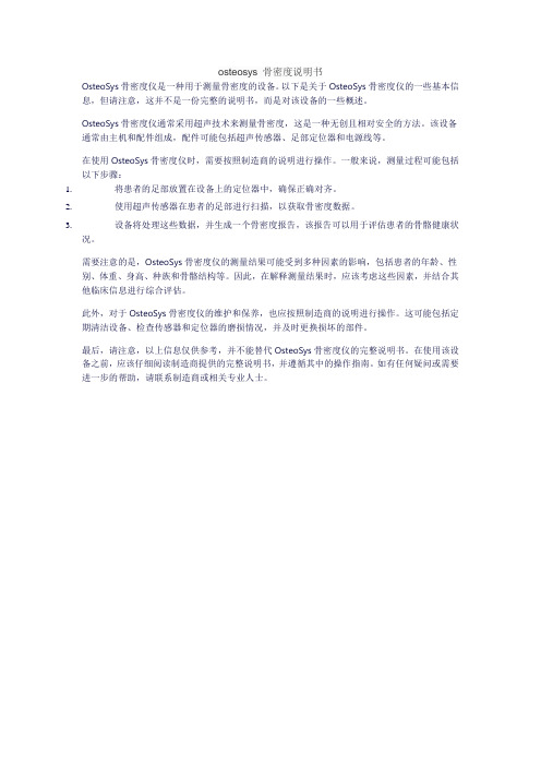
在使用OsteoSys骨密度仪时,需要按照制造商的说明进行操作。
一般来说,测量过程可能包括以下步骤:
1.将患者的足部放置在设备上的定位器中,确保正确对齐。
2.使用超声传感器在患者的足部进行扫描,以获取骨密度数据。
3.设备将处理这些数据,并生成一个骨密度报告,该报告可以用于评估患者的骨骼健康状
况。
需要注意的是,OsteoSys骨密度仪的测量结果可能受到多种因素的影响,包括患者的年龄、性别、体重、身高、种族和骨骼结构等。
因此,在解释测量结果时,应该考虑这些因素,并结合其他临床信息进行综合评估。
此外,对于OsteoSys骨密度仪的维护和保养,也应按照制造商的说明进行操作。
这可能包括定期清洁设备、检查传感器和定位器的磨损情况,并及时更换损坏的部件。
最后,请注意,以上信息仅供参考,并不能替代OsteoSys骨密度仪的完整说明书。
在使用该设备之前,应该仔细阅读制造商提供的完整说明书,并遵循其中的操作指南。
如有任何疑问或需要进一步的帮助,请联系制造商或相关专业人士。
超声骨密度仪操作说明书

超声骨密度仪操作说明书一、前言超声骨密度仪是一种用于测量人体骨骼密度的设备。
本操作说明书将为您详细介绍超声骨密度仪的使用方法和注意事项。
二、设备概述超声骨密度仪由主机、传感器、显示屏等组成。
主机是设备的控制中心,传感器用于测量骨密度数据,并通过显示屏将结果展示给用户。
三、操作步骤1.准备工作a) 确保使用环境安静,无明显干扰;b) 将超声骨密度仪连接至电源,并确保设备处于正常工作状态;c) 根据需要选择合适的传感器,并连接至主机。
2.患者信息录入a) 打开超声骨密度仪,进入初始页面;b) 根据屏幕提示,输入患者的个人信息,如姓名、性别、年龄等;c) 确认信息无误后,进入下一步。
3.操作示范a) 将患者就坐于测量椅上,并调整好姿势,保持舒适;b) 选择要测量的骨骼部位(如腰椎、髋部等),并将传感器应用于该部位;c) 按下开始测量按钮,仪器会自动进行测量过程;d) 在屏幕上显示完成提示后,可以移除传感器,并告知患者测量已结束。
4.数据解读a) 预测骨折风险:根据测量结果,超声骨密度仪可以预测患者骨折的风险,以帮助医生进行骨质疏松症的诊断;b) 数据分析:仪器会自动计算骨密度数值,并提供相应的评估报告;c) 结果解读:医生应根据测量结果及患者其他相关因素进行综合判断,以制定适当的治疗方案。
5.注意事项a) 患者安全:在操作过程中,应确保患者的身体安全,并避免造成不必要的伤害;b) 设备维护:定期维护超声骨密度仪,确保设备的正常运行,并定期进行校准以保证测量精确度;c) 数据保存:及时将测量数据保存,以备后续分析之用;d) 清洁卫生:使用完毕后,及时对仪器及相关部件进行清洁,保持设备的卫生。
6.故障排除a) 若设备无法正常启动,请检查电源连接是否正常;b) 若传感器无法正确连接,请检查连接是否牢固;c) 若测量结果异常,请检查设备是否需要进行维护或校准。
四、结语超声骨密度仪作为一种先进的骨密度测量设备,可为医生提供重要的骨质疏松症筛查和诊断依据。
超声骨密度仪操作使用说明

超声骨密度仪操作使用说明
一、开机校验步骤
1、检前连接电源打开电脑显示器、主机、系统电源开关、测
试。
2、正确放置骨模块靠近探测器,对齐标准线。
3、登系统界面- 点击日常检测- 测试 -进行仪器自动检测记
录自测结果。
二、单击测试 -新受检者
1、受检者ID:核对录入住院号或体检编号、姓名等基本信
息。
2、确认检测部位,正确摆放体位。
3、点击立刻测试 -确认-完成检测。
三、检后指导
1、点击查找受检者,可进行受检者信息修改,查阅打印报告
单,解读分析并进行健康指导。
2、点击主菜单返回。
四、退出程序
1、关闭主机,显示器断开电源,整理用物。
2、洗手做好日常登记工作。
详情见医务共享文件中《超声骨密度仪使用方法》视频。
骨密度设备SOP

设备管理文件骨密度设备 SOP 仪器档案仪器名称:超声骨密度仪 SONOST---3000 制造厂家:韩国 OsteoSys 供应商:北京格瑞朗博价值:启用时间: 2007 年 7 月 8 号仪器放置科室:骨密度检测室一、开机前准备 1. 确保电源线外皮没有损坏以免引起触电。
2. 如发现破损请马上与供应商联系。
3. 请使用单独电源。
4. 确保 SONOST—3000 使用单独的接线板。
二、校准日常检测校准系统减小误差幅度准确测量骨密度,通过每日检测提高系统的测试结果的准确性。
进行系统校准,在“ Home ”界面点选 <Daily Test> 键。
然后“Daily Test ”界面出现,当你点击<StartDailyTset> 键,日常检测开始。
如果检测成功,提示框“ Complete Daily Test ”出现并回到“ Home ”界面。
如果选择“ Time ”框,时间图表将出现。
如果选择“ Frequency ”框,频率图表将出现。
无论你什么时候进行校准,你需要使用随设备附带的骨模。
当你点击 <Start> 键,超声波开始产生 <Start> 键变成 <Stop> 。
在紧急情况下,点击这个键用于停止检测。
一般情况下,提示框“ Complete Daily Test ”伴随一声报警声出现点击 <OK> 键,校准完成。
超声骨密度仪器说明书

超声骨密度仪器说明书一、产品概述超声骨密度仪器是一种用于测量骨骼密度的设备。
通过利用超声波的特性,非侵入性地测量骨骼中的声速和衰减,从而得出骨骼密度的数据。
该仪器具有测量快速、无辐射、无创伤等优点,被广泛应用于临床检查、骨质疏松筛查和骨骼健康评估等领域。
二、产品特点1. 高精度测量:超声骨密度仪器采用先进的超声技术,能够对骨骼进行精确测量,提供可靠的骨密度数据。
2. 高效便捷:测量过程简单快速,无需特殊准备,只需将仪器放置在测量部位即可完成测量。
3. 安全无创:超声骨密度仪器使用无辐射的超声波进行测量,无任何损伤和副作用,安全可靠。
4. 多功能应用:该仪器不仅可测量骨骼密度,还可提供骨质疏松风险评估、骨骼健康指数等相关数据,为医生和患者提供全面的骨骼健康评估。
5. 数据管理方便:仪器配备数据存储和管理系统,可方便地查看、分析和导出测量结果,满足临床需求。
三、使用方法1. 准备工作:将仪器放置在平稳的工作台上,接通电源并开启仪器。
2. 患者准备:患者需脱掉鞋袜,坐于测量椅上,将待测部位暴露出来。
3. 测量操作:将超声探头贴紧待测部位,仪器会发出超声波进行测量,待测量完成后,仪器会自动显示骨密度数据。
4. 数据分析:根据测量结果,医生可结合患者的年龄、性别等因素,进行骨质疏松风险评估和骨骼健康指数计算。
四、注意事项1. 使用前请阅读说明书,了解仪器的使用方法和注意事项。
2. 仪器应放置在干燥、通风良好的环境中,避免暴露于高温、潮湿等恶劣条件下。
3. 使用过程中,应保持仪器的清洁和卫生,避免污染或损坏超声探头。
4. 为确保测量结果的准确性,测量时应避免患者有运动或咳嗽等干扰动作。
5. 使用过程中如遇到异常情况或故障,请及时联系售后服务人员进行处理。
五、维护保养1. 定期清洁超声探头,可用干净柔软的布擦拭,避免使用有腐蚀性的清洁剂。
2. 仪器长时间不用时,应断开电源并存放在干燥、防尘的地方。
3. 如需维修或保养,请联系售后服务人员,切勿私自拆卸或修理。
骨密度仪使用说明书
骨密度仪使用说明书一、产品介绍骨密度仪是一种用于测量骨骼密度的设备,是医学领域中重要的诊断工具之一。
它可以通过非侵入性的方法测量人体骨骼的密度,帮助医生判断骨质疏松症等骨骼疾病的风险。
二、安全注意事项1. 在使用骨密度仪前,请确保设备完好,并接通电源。
2. 骨密度仪通常需要使用X射线,因此在使用过程中应注意避免照射到非目标区域。
3. 如果您怀孕或者疑似怀孕,请在使用骨密度仪前咨询医生。
4. 使用过程中保持设备的稳定,避免摔落或碰撞。
三、使用步骤1. 准备工作a. 确保骨密度仪已接通电源。
b. 穿着合适的衣物,避免金属物品干扰测量结果。
c. 根据需要,选择不同的扫描模式和扫描区域。
2. 坐姿测量a. 按照仪器提示,坐在骨密度仪的测量座椅上,确保舒适稳定。
b. 保持身体直立,头部与仪器保持垂直,肩膀自然放松。
c. 跟随仪器的语音提示,完成扫描过程。
3. 立姿测量a. 按照仪器提示,站立在骨密度仪的测量区域上。
b. 双脚自然分开,与肩同宽,臀部和后背紧贴仪器。
c. 跟随仪器的语音提示,完成扫描过程。
4. 测量结果a. 测量完成后,仪器将自动计算出骨骼密度等相关数据。
b. 医生或操作人员可以通过仪器的显示屏或打印功能查看或保存测试结果。
c. 根据测量结果,医生将给出相应的建议和诊断。
四、维护保养1. 定期清洁仪器外壳,避免积尘和污垢影响仪器正常工作。
2. 如果发现仪器故障或异常情况,请及时联系供应商或维修人员进行检修。
五、环境要求1. 骨密度仪通常需要在室内环境下进行操作,温度和湿度应保持在适宜范围内。
2. 避免骨密度仪暴露在过高或过低的温度、湿度环境中,以免影响仪器性能和寿命。
六、附录:常见问题解答Q: 使用骨密度仪是否会对身体造成辐射危害?A: 骨密度仪使用的是低剂量的X射线,对人体健康影响较小,但仍需遵守仪器的使用说明,避免过度曝光。
Q: 如何保证测量结果的准确性?A: 在测量过程中,遵循操作步骤,保持身体放松稳定,避免移动,可以获得更准确的测量结果。
精准可靠的骨密度仪使用说明

精准可靠的骨密度仪使用说明骨密度仪是一种用于评估骨质疏松程度的仪器,它通过测量骨骼中钙盐和矿物质的含量来判断骨骼的强度和密度。
本文将介绍如何正确地使用骨密度仪,并提供一些建议,以确保测试的准确性和可靠性。
一、准备工作在开始使用骨密度仪之前,请确保仪器处于正常工作状态,并且已经校准。
同时,您需要按照以下步骤做好准备工作:1. 检查设备和电源是否正常连接,确保仪器能够正常开启和关闭。
2. 调整仪器的位置和高度,以适应被测试者的身高和体型。
通常情况下,被测试者应以站立姿势进行测试,双腿保持并拢。
3. 保证被测试者穿着合适的服装,最好是轻便舒适、不影响测试的服装。
二、测试操作步骤以下是使用骨密度仪进行测试的基本步骤:1. 提示被测试者进入测试区域并进行测试准备。
2. 将被测试者的身份信息输入到仪器中,并确保信息的准确性。
3. 让被测试者采取正确的姿势,双手自然垂放在身体两侧。
确保被测试者的身体重心平衡稳定。
4. 按下开始测试的按钮,骨密度仪将开始进行扫描。
在测试过程中,被测试者需要保持身体不动。
5. 测试完成后,仪器将显示测试结果。
您可以记录下结果,以备后续参考。
三、保养与维护骨密度仪是一种精密的仪器,需要定期的保养和维护,以确保其使用的准确性和可靠性。
以下是一些建议:1. 根据仪器厂商的指南,定期清洁仪器的表面,并确保仪器无尘无污。
2. 防止仪器接触水分和其他液体,避免损坏其内部部件。
3. 如果发现仪器出现故障或异常情况,请及时联系专业的维修人员进行检修。
四、注意事项使用骨密度仪时,还需要注意以下事项,以确保测试的准确性和可靠性:1. 在进行测试前,请确定被测试者没有穿戴任何金属饰品或其他可能影响测试结果的物品。
2. 确保被测试者在测试前至少两小时内没有接受过放射性物质注射。
3. 对于某些特殊人群,如孕妇、临床治疗中的患者等,请在使用骨密度仪之前咨询专业的医疗人员。
总结:骨密度仪是一种精确可靠的测试工具,可以用于评估骨质疏松程度和骨骼健康状况。
欧昊斯 3000 系列底座 说明书
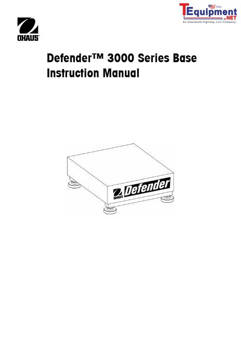
Defender™ 3000 Series Base Instruction ManualComplianceThis product conforms to the EMC directive 89/336/EEC and the Low Voltage Directive 73/23/EEC. Thecomplete declaration of Conformity is available from Ohaus CorporationDisposalI n conformance with the European Directive 2002/96 EC on Waste Electrical and Electronic Equipment(WEEE) this device may not be disposed of in domestic waste. This also applies to countries outside theEU, per their specific requirements.Please dispose of this product in accordance with local regulations at the collecting point specified forelectrical and electronic equipment.If you have any questions, please contact the responsible authority or the distributor from which youpurchased this device.Should this device be passed on to other parties (for private or professional use), the content of thisregulation must also be related.Thank you for your contribution to environmental protection.ISO 9001 RegistrationIn 1994, Ohaus Corporation, USA, was awarded a certificate of registration to ISO 9001 by Bureau Veritus Quality International (BVQI), confirming that the Ohaus quality management system is compliant with the ISO 9001 standard’s requirements. On May 15, 2003, Ohaus Corporation, USA, was re-registered to the ISO 9001:2000 standard.INTRODUCTIONThis manual covers installation, and maintenance instructions for the Ohaus Defender 3000 Series Base. Please read this manual completely before installation and operation.TMSAFETY PRECAUTIONSFor safe and dependable operation of this product, please comply with the following precautions:• Operate the base only under ambient conditions specified in these instructions • Ensure that the load cell cable does not pose an obstruction or tripping hazard • Do not operate the base in hazardous environments or unstable locations • Do not drop loads on the base• Do not lift the base by the top frame; always lift from the bottom frame when moving the base • Service should only be performed by authorized personnelINSTALLATIONUnpackingUnpack and inspect the product to make sure that all components have been included. The package includes the following:• Base • Weighing Pan • Warranty Card • Instruction ManualWhen purchased as a complete Defender 3000 Series Scale, will also include:• 3000 Series Indicator • Column AssemblyAssemblyWeighing PanPlace the weighing pan securely over the rubber load pads on the top frame of the base.Wiring ConnectionsConnect the load cell cable to an indicator using the wiring codes in Table 1 below. Refer to the indicator manual for information about load cell connections, setup and calibration.Note : When purchased as a Defender Series Scale, the base is already pre-wired to the 3000 Series Indicator.TABLE 1. SIX WIRE LOAD CELL CONNECTION.FUNCTION WIRE COLOR + Excitation Green - Excitation Black + Signal Red - Signal White + Sense Blue - Sense Brown Shield YellowSelecting the LocationTo ensure accuracy, proper performance and safety, locate and operate the base on a stable, level surface. Avoid locations withrapid temperature changes or excessive dust, air currents, vibrations, electromagnetic fields or heat.Level the base by adjusting the four leveling feet until the bubble in the level indicator (located at the rear of the base) is centered. A wrench may be needed to loosen the locking nut above each leveling foot. When the base is level, retighten the locking nuts up against the base to lock each foot into place.Note: Ensure that the base is level each time its location is changed.MAINTENANCECleaningThe base components should be kept clean and free of excessive material build up.•Damp cloth with water and a mild detergent may be used to wipe clean the external surfaces—do not use acids,alkalis, strong solvents or abrasive materials and chemicalsTroubleshootingAside from installing components and leveling adjustments, the Defender Series Base does not require any other adjustments asshipped from the factory.Operational difficulties that may be encountered can often be traced to simple causes such as:•Loose or incorrect wiring connections•Obstructions to the base frame•Unstable environments•Incorrect calibration or setup of the indicatorIf the troubleshooting section does not resolve or describe your problem, contact your authorized Ohaus service agent. Forservice assistance or technical support in the United States call toll-free 1-800-526-0659 between 8:00 AM and 5:00 PM EST.An Ohaus product service specialist will be available to provide assistance. Outside the USA, please visit our web site, to locate the Ohaus office nearest you.TECHNICAL DATATechnical SpecificationsThe technical data is valid under the following ambient conditions:Ambient temperature: -10ºC to +40 ºCRelative humidity: 10% to 90% relative humidity, non-condensingHeight above sea level: Up to 4,000mOperability is assured at ambient temperature -10ºC to +40 ºCTABLE 2a. SPECIFICATIONSD150BXD300BXD150BLD60BLMODEL D30BRD60BRCapacity 30 kg 60 kg 60 kg 150 kg 150 kg 300 kgResolution 6000d 6000d 6000d 7500d 7500d 6000dMaximumPan Dimensions 305 x 355 x 75 mm 420 x 550 x 80 mm 500 x 650 x 90 mmBase Construction Stainless Steel platform with painted steel frame and rubber leveling feetSafe Overload Capacity 125% of capacityRepeatability (std. deviation) 1dLinearity ±1d Load Cell Cable 2 m L x 6-wire 2.3 m L x 6-wireLoad Cell Type 350 Ohm, aluminum, single pointLoad Cell Excitation 5-15V DC/ACLoad Cell Rated Output 2mV/VLoad Cell Protection IP67Net Weight 9 kg 16 kg 28 kgShipping Weight 11 kg 19 kg 32 kgTABLE 2b. SPECIFICATIONSD150VXD300VXD150VLD60VLMODEL D30VRD60VRCapacity 30 kg 60 kg 60 kg 150 kg 150 kg 300 kgResolution 6000d 6000d 6000d 7500d 7500d 6000dMaximumPan Dimensions 305 x 355 x 75 mm 420 x 550 x 80 mm 500 x 650 x 90 mmBase Construction Stainless Steel platform with stainless steel frame and rubber leveling feetSafe Overload Capacity 125% of capacityRepeatability (std. deviation) 1dLinearity ±1d Load Cell Cable 2 m L x 6-wire 2.3 m L x 6-wireLoad Cell Type 350 Ohm, stainless steel, single pointLoad Cell Excitation 5-15V DC/ACLoad Cell Rated Output 2mV/VLoad Cell Protection IP67Net Weight 9 kg 21 kg 33 kgShipping Weight 11 kg 24 kg 37 kgDrawingsBase shown with 3000 series indicator and columnFigure 1. Defender Base Dimension Drawing.TABLE 3. DIMENSIONS.A B C D EBase Pan Depth Pan WidthHeight of Pan toSurface of Table*Height of Pan Depth Including Level Indicator D30BR, D60BR 355 mm 305 mm 123 mm 75 mm 380 mm D60BL, D150BL 550 mm 420 mm 136 mm 80 mm 575 mm D150BX, D300BX 650 mm 500 mm 143 mm 90 mm 675 mm D30VR, D60VR 355 mm 305 mm 119 mm 75 mm 380 mm D60VL, D150VL550 mm420 mm145 mm80 mm 575 mm D150VX, D300VX 650 mm 500 mm 154 mm 90 mm675 mm*For leveling purposes, the feet may be extended up to an additional 11mm.TABLE 4. ACCESSORIES.Description Part Number Column Kit, 35 cm painted steel 80251743 Column Kit, 70 cm painted steel 80251744 Column Kit, 35 cm stainless steel 80251745 Column Kit, 70 cm stainless steel80251746LIMITED WARRANTYOhaus products are warranted against defects in materials and workmanship from the date of delivery through the duration of the warranty period. During the warranty period Ohaus will repair, or, at its option, replace any component(s) that proves to be defective at no charge, provided that the product is returned, freight prepaid, to Ohaus. This warranty does not apply if the product has been damaged by accident or misuse, exposed to radioactive or corrosive materials, has foreign material penetrating to the inside of the product, or as a result of service or modification by other than Ohaus. In lieu of a properly returned warranty registration card, the warranty period shall begin on the date of shipment to the authorized dealer. No other express or implied warranty is given by Ohaus Corporation. Ohaus Corporation shall not be liable for any consequential damages.As warranty legislation differs from state to state and country to country, please contact Ohaus or your local Ohaus dealer for further details.*80251065*P/N 80251065 B ©2007 Ohaus Corporation, all rights reserved Printed in China。
骨密度仪操作手册

骨密度仪操作手册骨密度仪(Bone Densitometer)是一种常用于测量骨骼系统密度的医疗设备。
本操作手册旨在为用户提供关于如何正确操作骨密度仪的详细指导。
请用户在使用设备之前仔细阅读本手册,并按照要求进行操作,以确保准确的测量结果和使用安全。
一、设备介绍1. 设备外观及主要部件:骨密度仪外观呈矩形箱体,配备显示屏、键盘等操作部件。
2. 设备功能:骨密度仪主要功能包括骨密度测量、骨质状况评估等。
具体功能请参考设备说明书。
二、操作准备1. 设备准备:(1)确保骨密度仪已连接电源,并处于正常工作状态。
(2)检查设备连接是否牢固,所有部件是否正常。
2. 患者准备:(1)提醒患者穿着轻便舒适的服装,避免穿戴过重的金属饰品。
(2)询问患者是否存在与骨密度测量有关的医疗禁忌。
三、操作步骤1. 登记信息:(1)按照设备要求,在屏幕上输入患者相关信息,如姓名、性别、年龄等。
(2)根据需要选择特定的测量模式或骨密度测量部位。
2. 准备测量位置:(1)将患者安置在仪器所指定的测量位置上。
(2)确保患者的身体姿势正确和稳定,避免任何活动或移动。
3. 开始测量:(1)按下开始测量按钮,启动设备进行测量。
(2)在测量过程中,仪器可能会发出声音或震动,提醒患者保持稳定。
4. 测量结束:(1)待测量完成后,仪器会自动显示骨密度测量结果。
(2)记录测量结果并给予患者必要的解读和建议。
四、使用注意事项1. 设备维护:(1)定期检查设备连接部件,确保其牢固,如有松动应及时修复。
(2)保持设备清洁,避免灰尘或其他物质进入设备内部。
2. 使用安全:(1)在操作过程中,避免将手指或其他物体触摸到设备内部。
(2)严禁非专业人员擅自拆卸设备或进行维修保养。
3. 设备存放:(1)将设备妥善存放在通风干燥、温度适宜的地方。
(2)避免设备长时间放置不用,定期开机检查设备运行状态。
五、故障处理1. 常见问题解决:(1)如果设备无法启动,请检查电源连接是否正确。
骨密度仪使用说明
骨密度仪使用说明骨密度仪是一种先进的医疗设备,用于测量人体骨骼的密度以评估骨质疏松症的风险。
本文将为您提供骨密度仪的详细使用说明,以便您正确操作和解读测试结果。
第一步:准备工作1. 确认骨密度仪的完好性:首先,请检查设备是否完好无损,没有明显的外部损坏或故障。
如果发现任何异常,请联系您的供应商或专业技术人员进行维修或更换。
2. 了解仪器功能:在操作骨密度仪之前,对其各项功能和指示灯的意义有一定的了解非常必要。
请阅读设备的用户手册,熟悉每个按键和显示屏上的符号。
第二步:进行测量操作1. 控制环境条件:为确保测量结果的准确性,必须注意控制测试环境的条件。
房间应保持安静,温度适宜,并有足够的光线。
2. 建立测量档案:首次使用骨密度仪,或者测量不同个体时,请先建立测量档案。
根据设备的操作指南,输入被测试人员的相关信息,例如姓名、性别、年龄等。
3. 测量部位的选择:使用骨密度仪前,请确保确定测量部位。
通常,腰椎和股骨颈是最常用的测量区域,但不同型号的骨密度仪可能还提供其他测量选项。
选择合适的部位,并将被测试人员放置在仪器的正确位置上。
4. 正确的体位:被测试人员的体位对测量结果至关重要。
请确保被测试者保持平卧位或直立位,身体放松,并按照设备指引调整自己的姿势。
5. 启动测量:一旦被测试人员处于正确的体位并准备好,按下“测量”按钮开始测量过程。
此时,骨密度仪将利用特定的技术(如双能X射线吸收法)进行扫描和测量。
第三步:解读测试结果1. 等待测量完成:测量过程可能需要一些时间,请耐心等待设备自动完成扫描和测量。
在此期间,被测试人员应保持相对静止。
2. 分析结果:一旦测量完成,设备将生成一份结果报告。
注意仪器上的显示屏或连接的计算机上的结果图表,以及任何相关的数值数据和图像。
通常,结果以骨密度单位(如g/cm^2)或标准分数(如T值、Z值)表示。
3. 解读结果:根据设备的说明书,解读测试结果并进行风险评估。
不同的骨密度仪可能有不同的标准和参考范围,因此请参考设备制造商提供的相关资料。
超声骨密度测定仪技术参数
超声骨密度测定仪技术参数:
1设备用途说明:诊断骨质疏松症
2产地:原装进口
3测量方式:全干式超声波透射法,双向超声波传导与接收
4测量部位:足跟。
5★测量人群:0-100岁,且0-8岁按月测量的儿童月龄模式报告(应提供2个月以下婴儿按月龄测量报告一份)
6超声探头直径:≤20mm,适合婴幼儿测量
7★移动式永不磨损型非硅胶探头,内外不应有水囊、油囊等任何液体软囊,保证无须测量中更换探头。
探头中心频率范围:0.5MHz±1%或0.005MHz,保证探头的稳定性(应提供国家认可的检测报告证明)
8内置环境温度补偿和跟骨温度补偿双系统,无需预热加温。
9★内置热敏打印机和4英寸以上非触摸液晶显示屏
10★质量控制:主机内置自动电子质控系统及方案,无需使用质控模块(骨膜),减少误差。
(应提供热敏打印质控报告)
11★4级以上智能化可调节式脚台,避免脚大小对测量带来的影响。
12单机内置0-100岁年龄段数据库,并且可打印0-100岁热敏打印纸报告。
13具有数据统计功能和操控测量功能,且内置中国人使用的标准数据库,可形成EXCEL格式资料数据库。
14★参数要求:至少包括SOS、T值、Z值、%YAM值、%AGE值。
15测量时间:≤10秒
16测量精度:SOS<0.2%CV(应提供国家认可机构出具的检测证明报告)
17操作测量温度范围:10-35℃
18操作环境温度范围:-10-50℃
19操作湿度范围:35-80%RH(无冷凝)
20仪器重量:小于12kg。
DC-3000C系列超声厚度测量仪说明书
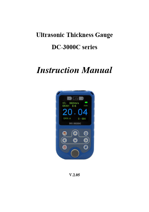
Ultrasonic Thickness Gauge DC-3000C seriesInstruction ManualV.2.05CONTENTS1. General Description ..................................................................... - 1 -2. Technical Specifications ................................................................ - 1 -3. Standard Delivery ........................................................................ - 2 -4. Overview the Display Unit ............................................................ - 2 -5. Keypad Functions ......................................................................... - 3 -6. Display Screen.............................................................................. - 4 -7. Preparation before measurement................................................. - 5 -【7.1】Preparation of the instrument .............................................. - 5 -【7.2】Selection of the Probe ........................................................... - 5 -【7.3】Treatment of the measured surface ...................................... - 6 -8. Basic Gauge Operations ................................................................ - 6 -【8.1】Switch on ............................................................................... - 6 -【8.2】Probe Zero ............................................................................. - 6 -【8.3】Contrast ................................................................................. - 7 -【8.4】Measurement mode .............................................................. - 7 -【8.5】Setting .................................................................................... - 9 -【8.6】Memory ............................................................................... - 12 -【8.7】Function ............................................................................... - 14 -9. Measuring technology ................................................................ - 16 -【9.1】Measuring methods ........................................................... - 16 -【9.2】Pipeline measurement method ......................................... - 17 -10. Maintenance and precautions .................................................. - 17 -【10.1】Power check....................................................................... - 17 -【10.2】Precautions ........................................................................ - 17 -10.2.1General precautions ............................................................ - 17 -10.2.2 Precaution during the measuring ........................................ - 17 -APPENDIX 1: Sound Velocity Measurement Chart..............................- 19 -1.General DescriptionThe Ultrasonic Thickness Gauge DC-3000C/DC-3020C is our new and improved readout unit with automatic probe recognition, automatic zeroing and a larger, more easily read LCD. It is a Multi-Mode thickness gauge that has the ability to measure through painted or coated surfaces and eliminate the thickness of the paint using a dual element style probe in echo-echo mode. This instrument can measure with very high resolution (0.01 mm or 0.001 inches) the thickness of metallic and non-metallic materials such as steel, aluminum, titanium, plastics, ceramics, glass and any other good ultrasonic wave conductor. The DC-3000C/DC-3020C accurately displays readings in either inches or millimeters.3. Standard Delivery-- Main Unit-- Standard 5MHZ probe D5301-- 75ML Couplant-- Build-in calibration block-- Cable (DC-3020C)--Carrying case--Operating manual--Certificate4. Overview the Display Unit1. LCD Screen2. Key Pad3. Battery Pack4. Probe connector5. Standard Test Block6. USB connector2 13 4565. Keypad FunctionsKey Function- On/ Off Key - Esc. Menu Press this key to switch on or off . Press this Key to Escape the Menu.- Menu Key - Confirm Key Press This Key to enter the Menu. Press this Key to confirm the selection.- Return Key - Storage Key Press this key to previous menu (DC-3000C) Press this key to store current data(DC-3020C)-Contrast-Adjustment Press this key to enter menu of Contrast and make adjustment- Up arrow Key Achieve switch among the menu options in the menu operation-Down arrow Key - Calibration Key Achieve switch among the menu options in the menu operation.Put the probe in the air, press this key to completethe manual calibration. (Under the measurement)- Left arrow key Achieve switch among the menu options in the menu operation. (under the measurement) -Right arrow key-Shortcut key Achieve switch among the menu options in the menu operation(under the measurement) Resolution setting between mm and inch6. Display Screen① Measurement ValueWhen it is under measurement condition, measurement value is in WHITE color. When users remove the probe, measurement value is frozen on the LCD and it is in BLUE color.② Current Velocity③ Current Probe model④ Gain setting⑤ Battery Life⑥ Resolution⑦ Measurement Mode⑧ Current memory location (DC-3020C)⑥ ⑤ ②①③④ ⑧ ⑦7. Preparation before measurement【7.1】Preparation of the instrumentFor the newly purchased instrument, please check the instrument and its accessory according to the “3 stan dard delivery”. If you find it is not the same as the table listed, please contact the manufacture in time. If the instrument is damaged, please do not use it and contact the manufacture as soon as possible.【7.2】Selection of the ProbeUsers can select the suitable probe according to the thickness of the workpiece to be measured.【7.3】Treatment of the measured surfaceWhen the surface to be measured is too rough or rusty heavily, please perform the treatment according to the following methods:1.Clean the measured surface by grinding, polishing or filing, etc. or use coupling agent with high viscosity for that.2.Use coupling agents on the workpiece surface to be measured. 3.Take multiple measurements around the same testing point8. Basic Gauge Operations【8.1】Switch onSelect the probe and insert it into the probe socket; and then pressto switch on the instrument, the screen displays: the Series No. and the version number.If you did not insert the probe before switching on the instrument, the screen will prompt you that “Plug in th e probe”, at this moment insert the probe into the socket and waiting to go to the measuring status. Notice: Please use the standard provided probe, otherwise the instrument will does not work normally and displaying “Error”.【8.2】Probe ZeroThe gauge does an automatic zeroing of the probe thus eliminating the need for an on-block zero. And then the gauge came into the measurement mode directly.Notice: Please make sure the probe is not coupled to the test piece when the gauge is first turned on and that there is no coolant on the end of the probe. The probe should also be at the room temperature, clean without any noticeable wear.【8.3】ContrastPress to easily enter into the contrast adjustment menu. (Under the measurement state)Press or to make fine adjustmentPress or to make rough adjustment【8.4】Measurement modeThere are 2 measuring modes provided, T-E mode and E-E mode .Users can select different measuring modes according to their requirements and measuring environments.Press into the measurement mode settingPress or to select desired measurement modePress to confirm selection,Press to Esc. Menu and into the measurement.8.4.1.1 T-E Mode:When the T-E mode is selected, all probes are available, and users can select following measuring modes:Standard Measurement:Display the current value, satisfied with the normal measuring needs.Minimum Measurement:Among one measurement, display the point. It is suitable for testing the curvature surface or needs to get the minimum value which is widely used in the thickness measurement of pipeline.Note: it is not recommended to use this function when measuring cast iron or alloy materials.Difference mode: (DC-3020C)Display the accurate differential value between the measured value and reference value set by the users, suitable for quality check to identifying the qualified products, whose thickness is in the admissive error.Average mode: (DC-3020C)Provides the average value of 2 to 9 measured points and display it suitable for testing the flat surface.Limitation setting: (DC-3020C)Set the upper and lower limit, when the measured thickness exceeds the preset limit, it will display and give alarm, this measurement mode is more widely used than differential mode.Scan:It is available for measuring the thickness of test piece with high temperature surface. The gauge will alarm for each fast measurement. And will display the all measured thickness upon the complete measurement finished.8.4.1.2 E-E Mode:When the E-E mode is selected, only probe D5301 is available. This function allows you to make measurement between two consecutive backwall echoes. Therefore, a good usage of the E-E option is for measuring through coatings (Max. 2mm) to measure only the true metal thickness. 【8.5】Setting8.5.1 Velocity rateSound velocity played an important role in measurement. Different material is of different sound velocity. When the sound velocity is incorrect, it will cause wrong measured results. There are two ways to select the material's sound velocity, which are Velocity selection and Velocity measurement.8.5.1.1 MaterialsThe gauge gives the sound velocity of 9 different materials which can be select by yourself. The 9 materials are: aluminum, titanium, steel, stainless steel, glass, copper, brass, polystyrene, cast iron.Press into“ SETTING” –“Velocity rate”-“Material”Press or to select material needed,Press to confirm.Notice: the 9 values are just the theoretic values, if users want to get accurate measurements , please refer to the”Velocity measurement”and get the more accurate sound velocity.8.5.1.2 Velocity inputWhen the sound velocity of 9 materials is not satisfied with the requirements of the users, there is a sound velocity table which gives the sound velocity of various materials in the appendix. Use this table to set the correct sound velocity. The usage is as follows:Press key into the menu- “SETTING”-“Vel. Rate”-“Vel. input”,Press or to move the arrow, press or to change the new velocity rate,Press to store this new Velocity.Press or to select the location where you want to store,Press to confirm.8.5.1.3 Velocity measurementBecause the workpiece is made from various materials and even the same material with different content and processing technology, the sound velocity will be changed and this change will cause the measuring error. If the error is not enough to influence the measuring accuracy, it can be neglect, otherwise it is necessary to get the accurate sound velocity of the workpiece to be measured. The “velocity measurement” can be used, the usage is as follows:Select T-E mode, Velocity can be neglect, and directly measure the sample which thickness is known.Press key into the menu- “SETTING”-“Vel. Rate”-“Vel measurement”,Press or to move the arrow, press or to change the value of velocity to determine the thickness as the same as the value of sample that is measured,Press to store this new velocity,Press or to select the location where you want to store,Press to confirm.8.5.1.4 Velocity storageThis function allows user to store 4 new velocities Rate.8.5.2 ResolutionUsers can select the displayed resolution. When selecting the high accuracy, the workpiece surface to be measured should be smooth, for the purpose of getting a accurate value.Press key into “Resolution”,Press or to select resolution and unit.1. 0.1 mm2. 0.01 mm3. 0.01 in4. 0.001 inPress key to enter/confirmNotice: When probe D5113 and D2012 is selected, it is recommended to use 0.1 mm and 0.01in.8.5.3 Probe CalibrationIt will cause error during the primary stage of usage and operating, this caused by the following three aspects:1. The probe itself or the temperature variation2. System error caused by the match of the instrument and the probe.3. Calculation error caused by the sound velocity set in the instrument is different from that of the actual material.In order to eliminate the possible error, please use following calibration method:Measure the test piece with known thickness. Get a measurement value, Press into menu-“SETTING”-“PROBE CALIBRATION”,Pressing or to adjust the measured value as the same as the value of sample that is measured,Press to confirm.Notice: Please notice that calibration range is within ±0.25mm. If it is out of range, which means users should replace a new probe.【8.6】Memory (DC-3020C)Press into the menu, and then go into “Memory”,the screen will display1 Memory unit2 Memory read3 Delete memory4 Data transferPress or into the selected item, press to confirm.8.6.1 Memory unitThe gauge has a memory capacity of 5,200 measurements. The memory location was composed by alphabet A-Z + location number. There aremaximum 200 test results in each alphabet. Users could set an Alphabet freely to store the test result.Press into the menu- “Memory”-“Memory unit”,Press or to select Alphabet A-Z which you wantPress to confirm.Press key to store each test result with a location number after take away the probe from the workpiece each time.Notice: Users cannot set location number; it begins as 000 andplus1automatically after users store each test result.8.6.2 Memory ReadPress into the menu- “Memory”-“Memory r ead”(Under the measurement),Press or to select desired Alphabet. Then the desired group of value can be readable by pressing or .8.6.3 Delete MemoryPress into the menu- “Memory”- “Delete Memory”(Under the measurement), Press or to select “Yes”or “No”. Press again to confirm the delete.8.6.4 Date Transfer1) Turn on the main unit and press into the menu-“Memory”- “Data transfer” (Under the measurement), press to confirm.2) Then connect PC with a cable in standard delivery. Meanwhile, LCD of main unit shows “Please keep the gauge and the PC connected” and new disk is auto identified;3) If it is completed, users double click U disk, then Alphabet shows on the screen of PC;4) Click each Alphabet, users could check the data stored in the formof .TXT or copy to Word or Excel for further analysis.【8.7】FunctionPress into the menu - “FUNCTION”, screen shows:1. Switch off mode2. Gain setting3. Language4. Contrast5. Default6. InformationPress or into the selected item, press to confirm. 8.7.1 Switch off modeAuto shut down after 1 Min. 3 Min. 5 Min. can be selectable.8.7.2 Gain settingPress into the “Gain adjustment”, the screen will display:1. High2. Medium3. Low4. AutomaticPress or to select desired itemPress to confirm.In the user's measuring environment, both different materials and the same material with different status will have different effects on the accurate and stable measuring. So for different measured objects and different measuring environment, users should adjust the work status of the instrument to meet more measurements.For many materials and measuring conditions, auto gain adjustment can be used, but for some special measurement, adjusting the instrument's working status is necessary. There are four different working modes: Auto, Low, medium and high.Auto: match different probe and meets almost all the measuring requirements.Low: Suitable for high scattering and small attenuation materials, Medium: Suitable for many measurements,High: Suitable for high attenuation material8.7.3 LanguageThe gauge provides English, Spanish, Portuguese, Japanese and Czech language for selection.8.7.4 ContrastUser can adjust contrast of display.Press or to make fine adjustmentPress or to make rough adjustment8.7.5 DefaultDuring the usage, when users can not ensure why the problems comes out and with some questions on setting, he can use this function to make the parameters to restore the factory status to eliminate any abnormal because of the parameters setting.8.7.6 InformationThe screen displays the version number and Probe Number.9. Measuring technology【9.1】Measuring methodsThe instrument provides many measuring methods.1.Single point measuring method: use the probe to measure any point of the workpiece to be measured and the displayed value is the thickness.2.Two point measuring method: Perform two measurements on the same point of the measured surface, in the second measurement, splitting plane of the probe should be 90 degree, take the minimum as the thickness value.3.Multiple point measurement method: perform several measurements in a circle about 30mm in diameter and take the minimum value as the thickness value.4. Continuous measurement methods: apply the single point measurement method, and take measurements continuously along the designated route, the intervals should be less than 5mm, and take the minimum value as the workpiece's thickness.【9.2】Pipeline measurement methodDuring the measurement, make the probe's crosstalk interlayer plate be perpendicular or parallel to the axial line of the pipeline. For a pipeline with larger diameter, the probe's crosstalk interlayer plate should be perpendicular to the axial line of the pipeline, but for pipeline with small diameter, users should perform measurements making the crosstalk being both parallel and perpendicular to the axial line of the pipeline and take the minimum readout as the thickness value.10. Maintenance and precautions【10.1】Power checkWhen the power is low, the low battery indicator will appear, at this moment users should replace the battery in time, or it will affect the measuring accuracy. The backlight cannot be switched on for a long time, because it is a big consumer of electricity.Note: if the instrument did not used for a long time, please take out of the battery to avoid leakage to damage the instrument.【10.2】Precautions10.2.1General precautionsThe instrument should avoid strong vibration, do not let it in an excessively humid environment, plug in or out the probe should hold the jacket to avoid the core wire of the probe damaged.10.2.2 Precaution during the measuring①During the measurement, only the measuring icon appears and displayed stable, it can be regarded as a good measurement.②If there are large quantity coupling agents attached on the measured surface, when taking away the probe, it will cause error. so when the measurement is completed, please move the probe away from the measured surface quickly.③If the probe wears out, it will cause the displayed value unstable, please replace the probe.DC-3000C SERIES ULTRASONIC THICKNESS GAUGE- 19 -。
超声骨密度仪维修需求书
3、对更换的零部件需保修一年以上;
4、维修完成后,使用科室需试用1个月。
四、维修付款方式
维修完成,使用科室试用1个月无异常后,维修方将相关维修工单及验收单、发票,交至设备科申请付款。
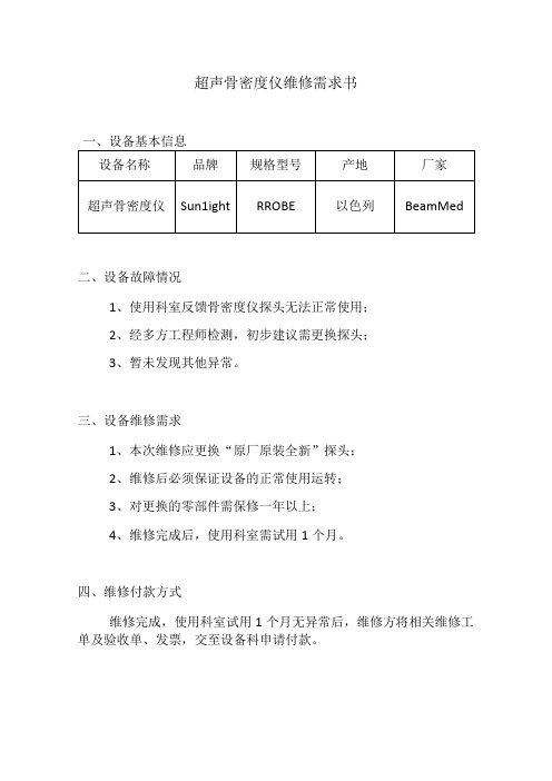
超声骨密度仪维修需求书
一、设备基本信息
设备名称
品牌
规格型号
产地
厂家
超声骨密度仪
Sun1ight
RROBE
以色列
BeamMed
二、设备故障情况
1、使用科室反馈骨密度仪探头无法正常使用;
2、经多方工程师检测,初步建议需更换探头;
次维修应更换“原厂原装全新”探头;
产品质保单
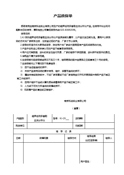
产品质保单
感谢使用由南京科进实业有限公司生产的超声经颅多普勒血流分析仪产品。
在使用中如出现问题影响您的使用,请致电我公司售后服务热线025-********。
保修说明:
1.K J系列超声经颅多普勒血流分析仪产品质保期为壹年,以产品交货日期为准。
请用户以联系码的方式与厂家联系注册,注册登记后的产品,厂家才予以保修。
2.保修的标准方式为寄修或送修,除非用户与厂家或代理商签有产品现场服务的约定。
3.产品中非科进公司安装认可的产品不能享受保修服务。
4.用户应对其数据、资料的安全性自行负责,厂家的维修不承担数据、资料损坏或丢失的责任。
5.消耗品不属于保修范畴。
6.在保修期内距保修期结束已不足三个月,维修更换的配件自更换之日起享有三个月的保修。
7.在保修期内以下情况恕不免费维修:
1)因不当运输造成的损坏;
2)未按产品使用说明的要求使用、维护、保管而造成的损坏;
3)擅自安装或删除软件,不经厂家同意或不经厂家指导自行开机并更换配件导致产品不能正常工作或损坏;
4)因用户维护不当或计算机感染病毒导致产品不能正常工作;
5)人为或不可抗力所造成的故障或损坏;
6)无故障产品的清洁或正常维护;
南京科进实业有限公司
(盖章)。
- 1、下载文档前请自行甄别文档内容的完整性,平台不提供额外的编辑、内容补充、找答案等附加服务。
- 2、"仅部分预览"的文档,不可在线预览部分如存在完整性等问题,可反馈申请退款(可完整预览的文档不适用该条件!)。
- 3、如文档侵犯您的权益,请联系客服反馈,我们会尽快为您处理(人工客服工作时间:9:00-18:30)。
超声骨密度仪OSTEO KJ3000系列保修说明
感谢您使用南京科进实业有限公司生产的超声骨密度仪产品。
在使用中如出现问题影响使用,请致电我公司售后服务热线(零25-836九二五九八)
保修说明:
1. 超声骨密度仪产品质保期为壹年,以产品交货日期为准。
请用户以联系码的方式与厂家联系注册,注册登记后的产品,厂家才予以保修。
2. 保修的标准方式为寄修或送修,除非用户与厂家或代理商签有产品现场服务的约定。
3. 非本公司安装认可的产品不能享受保修服务。
4. 用户应对其数据、资料的安全性自行负责,厂家的维修不承担数据、资料损坏或丢失的责任。
5. 消耗品不属于保修范畴。
6. 在保修期内距保修期结束已不足三个月,维修更换的配件自更换之日起享有三个月的保修。
7. 在保修期内以下情况恕不免费维修:
1) 因不当运输造成的损坏;
2) 未按产品使用说明的要求安装、使用、维护、保管而造成的损坏;
3) 擅自安装或删除软件,不经厂家同意或不经厂家指导自行开机并更换配件导致产品不能正常工作或损坏;
4) 因用户维护不当或计算机感染病毒导致产品不能正常工作;
5) 人为或不可抗力所造成的故障或损坏;
6) 无故障产品的清洁或正常维护。