EXATA 5.4源码下载调试
ESA数控折弯系统S540550中文操作手册v
1.3.1 要绘制的上模 ................................................................................................... 1.9
1.3.2 预设上模
...................................................................................................1.14
1.4如何输入一个新的上模 .....................................................................................................1.15 1.4.1 要绘制的下模............................. ........................................................................1.17 1.4.2 预设下模 ..........................................................................................................1.24
2.11.2 如何使用校正系数 ................................ .........................................................2.35
2.12 半自动模式校正 ................................ ..........................................................................2.36
ADXL345程序。(amoBBS阿莫电子论坛)
ADXL345程序。
(amoBBS阿莫电子论坛)之前是用C8051F340来驱动这个ADXL345的。
没问题。
现在想把这个程序移植到STM32上。
可是就是不行。
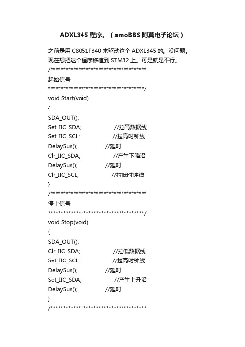
/**************************************起始信号**************************************/void Start(void){SDA_OUT();Set_IIC_SDA; //拉高数据线Set_IIC_SCL; //拉高时钟线Delay5us(); //延时Clr_IIC_SDA; //产生下降沿Delay5us(); //延时Clr_IIC_SCL; //拉低时钟线}/**************************************停止信号**************************************/void Stop(void){SDA_OUT();Clr_IIC_SDA; //拉低数据线Set_IIC_SCL; //拉高时钟线Delay5us(); //延时Set_IIC_SDA; //产生上升沿Delay5us(); //延时}/**************************************发送应答信号入口参数:ack (0:ACK 1:NAK)**************************************/ void SendACK(unsigned char ack){SDA_OUT();if(ack){Set_IIC_SDA; //写应答信号}else{Clr_IIC_SDA;}Set_IIC_SCL; //拉高时钟线Delay5us(); //延时Clr_IIC_SCL; //拉低时钟线Delay5us(); //延时}/**************************************接收应答信号**************************************/ unsigned char RecvACK(void){unsigned char CY;SDA_IN();Set_IIC_SCL; //拉高时钟线Delay5us(); //延时CY = READ_SDA; //读应答信号Clr_IIC_SCL; //拉低时钟线Delay5us(); //延时return CY;}/************************************** 向IIC总线发送一个字节数据**************************************/ void SendByte(BYTE dat){BYTE i;SDA_OUT();for (i=0; i<8; i++) //8位计数器{dat <<= 1; //移出数据的最高位if(dat&0x80){Set_IIC_SDA;} //送数据口else{Clr_IIC_SDA;}Set_IIC_SCL; //拉高时钟线Delay5us(); //延时Clr_IIC_SCL; //拉低时钟线Delay5us(); //延时}RecvACK();}/************************************** 从IIC总线接收一个字节数据**************************************/ BYTE RecvByte(){BYTE i;BYTE dat = 0;SDA_OUT();Set_IIC_SDA; //使能内部上拉,准备读取数据,SDA_IN();for (i=0; i<8; i++) //8位计数器{dat <<= 1;Set_IIC_SCL; //拉高时钟线Delay5us(); //延时dat |= READ_SDA; //读数据Clr_IIC_SCL; //拉低时钟线Delay5us(); //延时}return dat;}//******单字节写入******************************************* void Single_Write(unsigned char REG_Address,unsigned char REG_data,unsigned char SlaveAddress){Start(); //起始信号SendByte(SlaveAddress); //发送设备地址+写信号SendByte(REG_Address); //内部寄存器地址,请参考中文pdf22页SendByte(REG_data); //内部寄存器数据,请参考中文pdf22页Stop(); //发送停止信号}//********单字节读取***************************************** //uchar Single_Read(uchar REG_Address,uchar SlaveAddress) //{ uchar REG_data;// Start(); //起始信号// SendByte(SlaveAddress); //发送设备地址+写信号// SendByte(REG_Address); //发送存储单元地址,从0开始// Start(); //起始信号// SendByte(SlaveAddress+1); //发送设备地址+读信号// REG_data=RecvByte(); //读出寄存器数据// SendACK(1);// Stop(); //停止信号// return REG_data;//}//*********************************************************////连续读出ADXL345内部加速度数据,地址范围0x32~0x37////*********************************************************void Multiple_read(unsigned char SlaveAddress){unsigned char i;Start(); //起始信号SendByte(SlaveAddress); //发送设备地址+写信号if(SlaveAddress==ADXL345_SlaveAddress){SendByte(0x32); //发送存储单元地址,从0x32开始}else{SendByte(0x03);}Start(); //起始信号SendByte(SlaveAddress+1); //发送设备地址+读信号for (i=0; i<6; i++) //连续读取6个地址数据,存储中BUF{BUF[i] = RecvByte(); //BUF[0]存储0x32地址中的数据if (i == 5){SendACK(1); //最后一个数据需要回NOACK}else{SendACK(0); //回应ACK}}Stop(); //停止信号Delay5ms();}//************************************************************* ****//初始化ADXL345,根据需要请参考pdf进行修改************************void Init_ADXL345(){Single_Write(0x31,0x0b,ADXL345_SlaveAddress); //测量范围,正负16g,13位模式Single_Write(0x2C,0x08,ADXL345_SlaveAddress); //速率设定为12.5 参考pdf13页Single_Write(0x2D,0x08,ADXL345_SlaveAddress); //选择电源模式参考pdf24页Single_Write(0x2E,0x80,ADXL345_SlaveAddress); //使能DATA_READY 中断Single_Write(0x1E,0x00,ADXL345_SlaveAddress); //X 偏移量根据测试传感器的状态写入pdf29页Single_Write(0x1F,0x00,ADXL345_SlaveAddress); //Y 偏移量根据测试传感器的状态写入pdf29页Single_Write(0x20,0x05,ADXL345_SlaveAddress); //Z 偏移量根据测试传感器的状态写入pdf29页}。
飞马5214伪马电控JS5A0中英文安装使用说明书V1.1
JS-5A0全自动工业缝纫机伺服控制器AUOMATIC INDUSTRIAL SEWING MACHINE SERVO CONTROLLER安装使用说明INSTRUCTION MANUAL BOOK前言感谢您选用本公司的工业缝纫机伺服控制器。
本手册提供了使用该系统所需知识及注意事项。
l为了您更好地使用该产品,有使用之前请仔细阅读本手册。
您在使用中若有任何疑问或对我们的产品和服务有任何意见,请随时与我们联系。
主要技术数据供电电压范围:单相AC200V~AC240V±10%供电电源频率:50Hz/60Hz整机最大功率:700W电机额定功率:550W电机额定转速:6000rpm电机额定扭矩:0.6 N·m电机最大扭矩:1.8 N·m目录1 安全注意事项.........................................................................................................................- 1 -1.1 使用范围......................................................................................................................- 1 -1.2 工作环境:..................................................................................................................- 1 -1.3 注意事项......................................................................................................................- 1 -1.4 保养维修......................................................................................................................- 1 -1.5 危险提示......................................................................................................................- 1 -1.6 接线与接地..................................................................................................................- 2 -1.7 其它安全规定..............................................................................................................- 3 -2. 脚踏速控器前后踏力量的调整.............................................................................................- 3 -3. 操作面板说明........................................................................................................................- 4 -3.1基本框图.......................................................................................................................- 4 -3.2按键定义.......................................................................................................................- 4 -3.3按键操作.......................................................................................................................- 6 -3.4基本功能.......................................................................................................................- 8 -3.5指示灯...........................................................................................................................- 9 -3.6界面显示.....................................................................................................................- 10 -4. 参数说明..............................................................................................................................- 11 -4.1 包缝参数表(一区U)................................................................................................- 11 -4.2 包缝参数表(二区U.)...............................................................................................- 15 -4.3 工艺参数表................................................................................................................- 16 -5. 故障分析..............................................................................................................................- 18 -5.1 故障表........................................................................................................................- 18 -6. 接口及接线图......................................................................................................................- 20 -6.1接口板连接线及接口图(附图)..............................................................................- 20 - JIJU布边传感器.......................................................................................................................- 21 -7.1JIJU布边传感器外形..................................................................................................- 21 -1 安全注意事项1.1 使用范围本伺服控制器及其电机是专为工业缝纫机开发设计的,如果在其它方面使用,请注意使用者的安全。
5400调试手册
K 604504en-02 12 K 604504en-02K 604504en-02 34 K 604504en-02K 604504en-02 56 K 604504en-02K 604504en-02 78 K 604504en-02K 604504en-02 9+FU 变频器+MR 机房+NG 电源供应单元+S 井道+T 门2. 总的系统图2.1 电梯控制系统概览图K 604504en-02 112.2 串行或并行元件串行-并行元件2.3 串行和并行接口2.4 带闭环控制系统的同步电机带同步电机的变频器2.5 有机房控制柜控制柜内各元件分布K 604504en-02 13位置名称描述1 基础印板ASIXA 基础模块带控制模块2 有机房控制柜供电有机房电源模块3 制动器制动控制模块4 选项增加的选项模块5 DM236 仅对意大利6 机房墙上电源外部带主开关的电源模块7 RMVE 风扇继电器模块2.6 安全回路安全回路是由24V..52V直流电压供给和控制。
它弥补了安全回路电压由于长距离电缆和氧化开关等造成的损失。
安全回路断开,直流电压是52V!安全回路接触器2.7 井道信息井道信息由下列两个元素组成:·井道绝对值编码信息AGSI·电磁或光电开关KUET元件两侧跨接开关和编码器图K 604504en-02 15齿型带长度[m]+N(附加齿的数量)F[kg](对应力)15 6 324 10 545 19 880 33 15 齿型带涨紧以后,执行下列步骤:·进行测量运行·有必要的话调节”Tacho Factor”转速因素·检查平层精度有必要的话调节一下3.带SMLCD的用户接口3.1MX用户接口上的开关和显示带SMLCD的用户接口图位置名称1 电压供应状态和门触发灯2 安全回路诊断显示灯K 604504en-02 173.2 SMLCD主菜单SLMCD主菜单位置描述1 LON/BIO状态软件下载/冻结闪“%”正在下载软件到LON/BIO结点中“?”需要对LON-或BIO结点冻结闪“?”正进行冻结命令闪“!”冻结没有成功“!”冻结后丢失或出现新的LON/BIO结点空白冻结结束并且LON/BIO结点没有改变2 控制状态(M=有控制,空白=没有控制)3 服务访问状态(如果”*”在闪说明服务访问激活)4 轿厢载重是额定载重的百分之多少5 梯名和梯号位置描述6 驱动状态0 驱动停止+ 驱动加速= 驱动在正常速度_ 驱动在减速F 驱动无效? 状态未知7 轿厢状态= 轿厢在门区并且停止# 轿厢停在门区外向上运行向下运行? 状态未知8 当前楼层所在值(1到n)9 运行控制状态(根据不同的错误情况显示不同的错误运行控制号码)10 显示在失电情况下轿厢在最近楼层的上面还是下面.最近楼层可以看位置8,如果轿厢停在门区,也可以看位置11。
4500韦伯触摸屏软件调试说明书
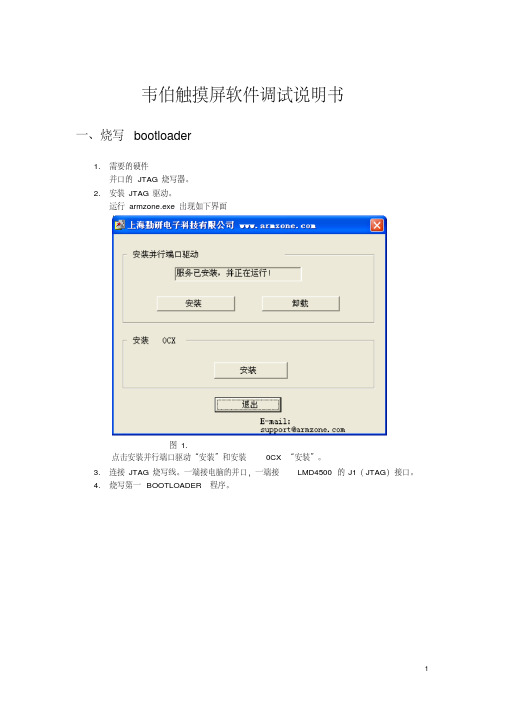
韦伯触摸屏软件调试说明书一、烧写bootloader1.需要的硬件并口的JTAG烧写器。
2.安装JTAG驱动。
运行armzone.exe 出现如下界面图1.点击安装并行端口驱动“安装”和安装0CX “安装”。
3.连接JTAG烧写线。
一端接电脑的并口,一端接LMD4500的J1(JTAG)接口。
4.烧写第一BOOTLOADER程序。
图25.点击nboot1st.bat.出现如下界面。
图3.注意红框的部分,如果和里面的内容不同,请检查驱动是否安装好。
JTAG线是否连接好,LMD4500 是否上电。
6.选择K9S1208 prog 即输入”0”。
出现下图界面。
图47.选择K9S1208 Program 即选择“0”.出现如下界面图58.输入block number 是“0“.出现如下界面图69.等烧写完之后出现如下界面。
图79.输入“2“结束第一个bootloader的烧写。
10.第二个bootloader的烧写。
运行“nboot2nd.bat “出现的界面如图 3.输入”0“之后出现图4界面。
再输入”0“之后出现图5界面。
此时要注意输入的block number 是”2“.然后出现图6界面。
烧写完成之后出现图7界面。
输入”2“结束烧写。
11.第三个bootloader的烧写。
运行“QT2440_Amon.bat “出现的界面如图 3.输入”0“之后出现图4界面。
再输入”0“之后出现图5界面。
此时要注意输入的block number 是”8“.然后出现图6界面。
烧写完成之后出现图7界面。
输入”2“结束烧写。
二、烧写NK1.运行DNW .出现如下界面:图1.2.连接串口线,一端接电脑的串口,一端接板子的P3.点击Serial Port 菜单的connect,出现如下界面图2.3.板子上电后,在DNW界面中出现“*”后输入“u”。
图3.图4.4.插入USB线,后按空格键,出现如下界面。
图5.5.选择1,按回车后界面如下:图6.6.选择USB Port—>Transmit ,找到nk.nb0。
新手必读教材,亚拓450组装到调试全套图文详细讲解
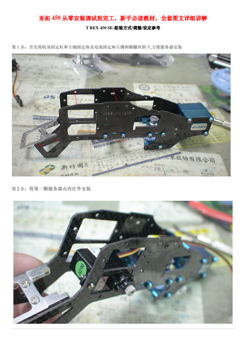
亚拓450从零安装调试到完工,新手必读教材,全套图文详细讲解T REX 450 SE-组装方式/调整/设定参考第1步:首先将机身固定柱和主轴固定座及电池固定座左侧两颗螺丝拆下,方便服务器安装第2步:将第一颗服务器由内往外安装第3步:同样的由内往外安装第二颗服务器,并将讯号线排列整齐用速线带固定,切记,1.速线带头在机身内侧2.在固定于册版的地方用透明胶带包覆两圈,防止组装时讯号线破损第4步:将伺服机讯号线由内侧版经沟槽穿往机身外侧第5步,将服务器的讯号线整理后,再用蛇管包覆第6步:将机身固定柱和主轴固定座及电池固定座左侧两颗螺丝装回原来位置记得要上螺丝胶喔第7步:将中间的侧版固定柱套入,并对准螺丝孔.将马达固定座装上下侧版第8步:1.利用马达固定座将上.下侧版组合2.将中侧版固定柱锁上螺丝第9步:将服务器讯号线穿过上.下侧版并将左侧三颗螺丝锁上第10步:右侧版先锁上1的螺丝,其它两颗先不锁第11步:将所需的马达同齿固定后,在将马达固定在马达坐上第12步:将马达线穿过机身底板和组装好的脚架,并将脚架固定第13步:将皮带穿过尾管(注意皮带的方向性)并将尾服务器座套入尾管,然后跟机身组合,并将垂直/水平/支撑架装上,调整皮带的松紧度后上紧尾管固定座的螺丝第14步:金属尾传动轮座组固定前,需确认与尾管固定座呈平行状态第15步:陀螺仪的整线后用蛇管包覆第16步:将陀螺仪用双面胶固定在尾管固定座上后,将包覆好的讯号线穿过上.下侧版后再将右侧版的两颗螺丝上紧(陀螺仪安装在尾固定座的下方,以防炸机时被副翼打到)第17步:先抓出尾服务器的中点,并将球头固定在服务器的摆臂上(上下两个圈是行程终点),并将服务器固定在尾伺服座上第18步:装好尾服务器时,套上连杆后,注意,这是重点1,尾舵控制组需在尾主轴中央2.调整尾服务器座让连杆跟尾管平行3.尾服务器摆臂球头需在中点4. 尾连杆和尾管尽量跟尾管呈平行以上确定后在固定尾伺服座螺丝第19步:1.将主轴上的连杆按说明书上的长度组装,并套上摆臂平衡杆先量好两边相等长度后套入平衡杆重垂在装上平衡翼2.将主轴和机身组合第20步:组合好后请注意大齿盘于机身的间隙,不能摩擦到机身或尾传动轮第21步:调整马达铜齿的高度并将铜齿固定螺丝上紧,调整马达与大齿盘的间隙后再将马达固定螺丝上紧第22步:1.用2mm钻尾将欲锁球头的摆臂扩孔2.将球头利用螺母固定在摆臂上3.将多余的摆臂去掉.以免摆动时干涉4.将服务器连杆依说明书长度组装好第23步:将组装好的摆臂套上服务器,先不上服务器螺丝,以便调整时需拆下,此时连杆都是呈垂直状态第24步:接收的整理1.用热缩套管或由机的油管将接收线的前端包覆,以防接收线和侧版接触而出现干扰现象,相信很多人有这个经验2.用1mm的泡棉将接受包覆并用透明胶带在包覆,以防日久泡棉脱落,这可以防止摔机后的碰撞以以多一层的防干扰的作用第25步:1.用双面胶将接收固定在底板2.将讯号线接上接收第26步:1.用打火机熏烤将热缩套管定型你要的角度2.在用热缩套管将整理的接收线固定在线管上第27步:将电子变速器的讯号线穿过脚架和底板之间并接上接收(马达线先不要接,以便遥控器设定和调机)-----------------------------------以上是机械及电子部件的安装--------------------------第28步:控的设置,打开遥控器进入SWASH TYP,打开选项选择120度第29步:接上电池,将摆臂尽量以90度脚平行装上,并推油门游戏杆以确认伺服机的方向正确,如有反向,可进入REV.SW个别调整正确方向第30步:如摆臂有微些差距,可进入sub trim个别微调至所有摆臂至平行,调整好后记得看看十字盘是否平行,如没平行,调整十字盘连杆使起平行既可第31步:接下来先将主旋翼做好静态平衡后,装上直升机,并将服务器螺丝锁上第32步:进入遥控器选项里的PIT.CURV.1.并将油门游戏杆推至中点2.在NORM设定页面3.将EXP显至ON 的位置,这可以自行调整曲线较为顺畅第33步:已有贴配重贴纸的桨为主1.将螺距规套上,并以螺距规的上沿跟平衡杆呈平行2.此时应为0度,如没0度,可依差距大小调整连杆使其成为O度第34步:将油门游戏杆推至最高并记下为+11度第35步:将油门推至最低,并记下为-11度,对高手来说,这个螺距应该是可以的第36步:如想减少螺距行程,可进入swash mix的PIT降低%数(5%为一度左右),所以我降了10%,此时螺距为(-9 0 +9)这应该适合一般飞友第37步:接下来是在进入PIT. CURV设定NORM的螺距,第一点位置设定为-2度,此时数据为38%第38步:接着将油门游戏杆推至中点3的位置(约是停悬点),为+5度,此时该点数据为75%第39步:在来是将刚刚设定的38%和75%以及最高的100%三点中的曲线,设定调整一条顺畅的拋物线,这样一来,在操控的过程会顺畅许多,不会又高高低低的情况发生第40步:接下来进入THRO CHRV的NORM页面设定油门曲线,首先在第3点(中点)位置将数据设定为68%第41步:接下来是一般人常遇到也是最让你头痛的尾巴设定,如果你刚刚再组装的时候有按照图示安装,基本上尾服务器的中立点已经抓好了,所以不会有偏的问题发生,只要了解陀螺一的功能和调整就可以了,A.接上电源如果灯恒亮,就表示锁头模式,1数字/模拟的切换开关,如果你用的尾舵机不是数码的,必须将开关切至OFF的位置,如果是数码舵机择切换至ON的位置2.陀螺仪反向开关3.延迟开关,如果是数字服务器这个开关可以不用管他,在O的位置.如是用模拟服务器,感度以将很低仍有追踪现象,可调整此开关改善4.陀螺仪行程开关,如行程太大会产生操控尾舵时,定点会有抖几下的情况,可降低此行程来改善第42步:确认方向舵方向,通常尾舵控制组跟方向游戏杆是反方向移动,这才是正确的第43步:确认好后接下来进入遥控器GYRO SENS AUTO页面设定陀螺仪感度POS.0为一般飞行感度设定POS.1为3D飞行感度设定设定好感度后不要忘了也要进入由上角将POS.0和POS.1个别设定好如此一来,感度才会跟着你切换的飞行模式而改变第44步:设定好后,将电子变速器和马达的线依颜色接上,并将固定第45步:设定的过程中,有些飞友会利用这个页面调整服务器的行程,来达到所需的螺距,这是错误的,就算调整好了,+-数据不相等,这会产生打动作时,左右的速度不均现象第46步:还有一种错误的调整螺距的方式,如图示,降低/提高螺距曲线的%数来迎合所需的螺距,这也会让你在操控时,游戏杆上下不均匀,也缩短了螺距变化的空间,所谓一步错步步错!第47步:接下来是调整双桨,以量螺距的桨为机准桨(贴配重贴纸的桨),此桨不动视另一只桨高低作调整就可以了,完工!资料来源:亚拓台湾官网论坛编辑制作:5IMX之dtjj(欢迎传播,功德无量)。
Ver5.0调试软件功能简介及使用说明书
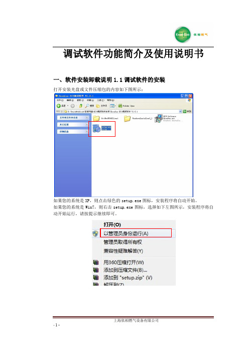
一、软件安装卸载说明 1.1 调试软件的安装
打开安装光盘或文件压缩包的内容如下图所示:
如果您的系统是 XP,则点击绿色的 setup.exe 图标,安装程序将自动开始。 如果您的系统是 Win7,则右击 setup.exe 图标,选择如下左图所示,安装程序将自 动开始运行,请按提示继续即可。
1.4L 1.6L 1.8L 2.0L 2.4L 3.0L 1.8T 2.0T
LPG
1.6 1.8 2.0 2.0 2.2 2.6 2.4 2.6
CNG
2.0 2.0 2.2 2.2 2.4 2.6 2.6 2.8
注释:
- 11 -
上海依相燃气设备有限公司
A:燃油时的喷油脉宽 B:燃气时的喷油脉宽 C:燃气时的喷气脉宽 C=全段比例×B+全段偏移 减压器压力和喷轨孔径按上述设定好后,开始调试,调试的步骤为:
缸序选择:选择正向时,即采集喷油信号一、二、三、四缸后,转化的喷气信号对 应一、二、三、四缸;选择反向时,即采集喷油信号一、二、三、四缸 后,转化的喷气信号对应四、三、二、一缸。
注:此选项请慎重更改,错误更改后有可能导致自动标定时发生非正常熄火,高速 滑行熄火、怠速不稳等情况;
- 10 -
上海依相燃气设备有限公司
第二步 燃气开环调试: 使发动机转速瞬间加到最高转速,加速瞬间听发动机声音是否发闷(正常情
况下是清脆的声音)最高转速是否和燃油一样(可对比燃油同工况下的现象),如果 加速瞬间发动机声音发闷,最高转速低于燃油最高转速,可以尝试把分段偏移的 10ms 以上的区间减小,再次试验看现象有无好转,如果效果不明显,可以尝试降低全段 比例的数值,再次试验,直至上述现象消失;
气脉宽(G.inj)、燃气温度(T.Gas)七个实时数据。 油气脉宽区:显示八个缸的油气脉宽(根据实际缸数而定,无信号则显示 0.0ms) 通讯指示灯:通讯指示灯蓝绿色交替闪烁,表示通讯成功
(分享)使用CCS5下载调试StarterWare例程代码的方法(1)

1分享如何使用CCS5下载调试StarterWare例程代码首先说明一下为什么需要了解或者学习StarterWare。
个人认为第一点是,StarterWare软件中包含有大量例程,均可查看源代码,在初期学习阶段,借助于StarterWare有助于深入了解AM335x的硬件(可为操作系统驱动程序打下一定基础);第二点就是StarterWare实时性好,使用简单,在不需要OS的场合有很大的价值。
我按照的版本是StarterWare_02_00_00_07,支持AM335x,包含有AM335x Starter Kit开发板的例程。
CCS版本是5.2,官方下载,连接Starter Kit无需破解(CCS识别到TI自家的仿真器或者开发板时,无需license)。
StarterWare所有例程的工程文件所在目录为:\AM335X_StarterWare_02_00_00_07\build\armv7a\cgt_ccs\am335x\evmskAM335x ;所有工程的*.c和*.h源文件所在的目录是:\AM335X_StarterWare_02_00_00_07\examples\evmskAM335x;使用CCS重新编译工程所生成的*.bin可执行文件和*.out下载文件目录是\AM335X_StarterWare_02_00_00_07\binary\armv7a\cgt_ccs\am335x\evmskAM335 x。
1.1 加载所有例程可以使用CCS5一次性加载所有的例程到当前workspace中,步骤如下:1,打开CCS5.2,点击主菜单File→Import…,弹出如下对话框,并选择其中的“Code Composer Studio →Existing CCS Eclipse Projects”,并点击下方的“Next”按钮。
2,点击上图中的“Next”按钮后,弹出如下对话框:按钮,选择目录如下图所示:并点击下方的“确定”按钮。
step7v5.4的安装和升级方法
STEP7 V5.4官方中文版下载简介:西门子STEP7 V5.3 SP2 中文版下载西门子 step7 V5.3是用于SIMATIC S7-300/400站创建可编程逻辑控制程序的标准软件,可使用梯形图逻辑、功能块图和语句表进行编程操作。
PCD1 和 PCD2 Saia-PCD 控制设备也可以用 Siemens Step7 来编程。
使用Step7编程可以在Saia PCD 上实现某些集成在Step7内的功能.不只是兼容在常规功能之外还具备以下的特点:DK 3964 R/RK 512 等标准协议已经集成到控制器内,不需要额外驱动MPI 接口集成 modem 支持: 内置modem 功能,可进行远程编程、诊断或数据传输编程不需 MPI 转换器,直接通过PC上的 RS232 口现场总线通讯功能. 控制器功能中已集成了Profibus DP Master / Slave, Profibus FMS 和 LONWorks.利用web server进行监控. 储存 HTML 网页、图片、PDF 文件等到控制器里供通用浏览器查看扩展操作系统功能如保护技术秘密,防止被非法查看或复制用Siemens 原装Step7编程直接运行Step7程序,毋需转换兼容普遍使用的编程环境,使用熟悉的编程测试功能用STL, LAD, FBD编程使用Siemens工程工具,监视修改变量,程序状态等相同指令集 (Siemens S7-300 和S7-400系列)一些特殊功能,如串口通讯、计数等可在系统功能 (SFCs)中编辑Step7 v5.3 Professional 正确安装方法Step7 v5.3 Professional 安装步骤1 安装Windows 2000 SP4/xp Professional+SP1/SP2 (xp home除外)2 安装 IE6\IE6b2800\ie6setup.exe3 设置 Windows 2000 默认语言为"英语(美国)"控制面板->区域选择->设置默认值, 选择"英语(美国)"4 安装Step7 v5.3\ STEP7_PROFESSIONAL_2004\Setup.exe注: 源文件的路径不能有汉字, 否则Setup.exe不能执行选择: Step7 v5.3S7-SCL v5.3S7-GRAPH v5.3 (Graph 7 )S7-PLCSIM v5.3 (PLC仿真)Aotomation License Manager v1.1选择语言:English提示: Transfer License KeysYes, Transfer should take place during installationNo, Transfer license keys later选择: No, Transfer license keys later5 恢复Windows 2000 默认语言为"中文(中国)"6 安装 Step7 v5.3 和Graph v5.3授权将"\Step7 v5.3+graph5.3授权"目录拷贝到硬盘执行STEP7V53key.exe安装 Step7 v5.3授权A1710453执行s7graph53.exe安装Graph v5.3授权A1S7GR53注: 我并没有先装Step7 v52有些朋友将WIN2000的"当前用户的设置/您的区域设置"设为英语,这是没有用的,应将"系统的语言设置/设置默认值"设为英语才有效安装与运行环境STEP 7是面向MS Windows 2000 Professional和MS Windows XP Professional而发布的。
E4AZ E5EZ温度控制器通讯功能

E5AZ/EZ/EZ-PRR/CZ 支持串行通信,包括 CompoWay/F 和 Sysway。 本用户手册对 E5AZ/EZ/EZ-PRR/CZ 的通信功能进行说明。 在使用 E5AZ/EZ/EZ-PRR/CZ 之前,请务必认真阅读本手册,并充分理解,以确保正确的使用。 另外,阅读之后请妥善保管本手册,以便随时取阅。
I
安全注意事项
●用于保证安全的标识及其含义
为了安全使用 E5AZ/EZ/EZ-PRR/CZ,在本手册中用以下标识和符号来表述注意事项。 在此所表示的注意事项是有关安全方面的重要内容。请务必遵守。 标志及其含义如下所示。
注意 如果操作不当,其引起的危险程度会引起轻度/中度伤害或者 物品损坏等。
●图标说明
III
安全使用注意事项
请确保遵守以下注意事项以保证安全使用。 (1) 请勿在下列环境中使用
z 有水、油等飞溅的地方 z 阳光直射的地方 z 有粉尘、腐蚀性气体(尤其是硫化气体、氨气等)存在的地方 z 温度变化激烈的地方 z 会产生结冰、凝露的地方 z 振动或冲击很强烈的地方 z 会直接受到加热机器辐射热的地方 (2) 为了防止火灾和触电,必须在相对远离污染源并且可控制的环境中使用。 (3) 在各型号规定的温度和湿度范围内使用和储藏温控器,当二个或多个温控器水平紧靠安装或垂直紧安装时,由于温 控器的热辐射会导致内部温度上升而降低使用寿命。这种情况下,需要采取风扇强制冷却或其它通风措施来降低温 控器的温度,但是,小心不要单冷却接线端部分以避免造成测量误差。 (4) 为了不妨碍散热,温控器周边请勿封闭。温控器本身的通风孔也不要堵塞。 (5) 配线用压接端子请使用指定尺寸(M3.5、宽 7.2mm 以下)的端子。 (6) 配线用材料,请使用 AWG24(截面积 0.205mm2)~AWG18(截面积 0.832mm2)的电线,剥线长度 5~6mm。 (7) 请确认端子的极性,做正确的配线。 (8) 不使用的端子,请勿连接。 (9) 内部电路和电压输出(控制输出)不是电隔离的。当使用一个接地温度传感器时,不能连接任何控制输出接地端。 否则不明电流会导致计量错误。 (10) 为了避免感应噪声,温控器的接线板的接线应远离高压线或大电流的电源电缆,同样不要让电源线一起走线或平行 于温控器连线。推荐使用单独的管道屏蔽线。在可能产生噪声的外围设备上安装浪涌吸收器或噪声过滤器,例如电 感应设备(如电机、变压器、螺线管圈、磁性线圈等)。在电源上使用噪声过滤器时,除了确认其电压和电流值外, 还应尽可能近地安装在温控器附近。将温控器及其电源尽可能地远离产生强大的、高频波(如频焊接机、高频机器 等)的设备和产生浪涌的设备。 (11) 电源电压及负载,请在规格、式样范围内使用。 (12) 为了使电源投入时在 2 秒内到达额定电压,请借助开关、继电器等进行瞬间加载。如果电源电压缓慢增加,温控器 没有复位,输出可能会有误动作。 (13) 使用自调节时,同时打开温度控制器和负载(如加热器),或在温控器打开前接通负载。如果在接通负载前打开温 控器电源,则不能再进行正确的自调节和实现最优控制。预热完成后开始操作,预热一完成即断开电源,然后同时 打开温控器和负载。(也可以通过从停止模式转换到运行模式得以实现这种温控器的电源关闭。) (14) 电源启动后经约 2 秒钟输出才开启,在配置控制回路时请给予充分的考虑。 (15) 请设置作业人员能够马上关上电源的开关或断路器,并做适当的表示。 (16) 请确认至少有 30 分钟以上的预热时间。 (17) 切换成初始菜单时(菜单切换时)若输出为 ON 的状态将会变为 OFF,请考虑到这一点再进行操作。 (18) 切断电源时,请借助开关、继电器等进行瞬时切断。如果缓慢切断电源会导致输出误动作和存储器异常等。 (19) 当要延长热电偶的导线时,要使用与热电偶类型相匹配的补偿导线,不要延长铂电阻的导线。只能使用低阻值的导 线(每根最大 5Ω),并且保证三根导线的阻值都是相同的。 (20) 请将 OPTION 模块安装在正确的位置。安装时,请不要将本体内部的其它基板取下。 (21) 当温控器从机壳中抽出时,不能用力过大,以免使温控器发生变形或损坏。 (22) 当将温控器从后机壳中抽出更换时,要检查端子的状态;若使用腐蚀过的端子,由于端子金具接触不良有可能会导 致温控器内部温度上升以致引起火灾。在这种场合下,将后机壳一起更换。 (23) 将前盖插入后外壳时,若无法顺利进行,请不要勉强插入,因为可能会损坏内部的其它元件。 (24) 可直接由前盖取出的温控器,在取出前需先关闭电源,请绝对不要用手触摸端子或电子部品,或者给予冲击。插回 时,请不要让电子部品与外壳接触。 (25) 静电能够损坏内部部品,在用手拿温控器前,一定要先触摸一下与地相连的金属物,以释放手上的静电。在抽出温 控器时,不要接触到板上的电子部品和电路;但用手拿温控器时,抓住前面板的边缘部分。 (26) EEPROM 的写入次数是有寿命的。通过通信等频繁写入数据的场合请使用 RAM 写入模式。 (27) 关于清洁:请勿使用油漆稀释剂,请用标准等级的酒精。 (28) 请使用工具来分离部品,以免受到内部锐利部品的伤害。
ESX4和ESX3.5调试安装带图指导,不信调不好-convert+error

More on "ERROR: Failed to take snapshot ...drbking 7 posts sinceFeb 28, 2009I have seen previous posts on this and have tried to follow all of the suggestions but nothing is helping. I am running XP and have two hard drives, both NTFS and both have plenty of room. My destination is an external hard drive, FAT32, also with plenty of room. I am getting the message *ERROR: Failed to take snapshot of a source volume.P*ossible causes include not having any NTFS volumes on Windows XP or Windows 2003 source systems, and not having enough free disk space.I installed the converter as an administrator, I have rebooted multiple times, I ran checkdsk /f on both hard drives and the external drives, I have turned off all of the services that I am comfortable turning off, but I just keep getting this message. I've attached the log file.Thanks for any help. Attachments:•vmware-converter-7.log (149.4 K)ryan.gallagher37 posts sinceJul 2, 2006Reply1.Re: More on "ERROR: Failed to take snapshot of a source volume". Mar 1, 2009 6:11 PM Is the volume shadow copy service (vss) enabled and started? Does "vssadmin list shadows" produce anything? What does "vssadmin list volumes" output?Any chance you could try Converter 4.0 instead of 3.0.3? You'll probably have the same issue, but the logs may be more informative. Thanks,-Ryandrbking7 posts sinceFeb 28, 2009Reply2.Re: More on "ERROR: Failed to take snapshot of a source volume". Mar 2, 2009 5:39 AMin response to: ryan.gallagherThanks very much for your reply. The volume shadow copy service was enabled and started before I ran the program. Now that the program has failed (more on that in a minute), it shows that it isn't started.I assume vssadmin list shadows is something to run at a DOS prompt? It returns Error: 0x8000ffff.I tried running 4.0 as you suggested. The first three times it failed, just as 3.0 had failed. Each time I removed the history of the failed attempted, rebooted, and tried again. On the fourth try it ran for about 12 hours and then failedat 94% with a new message "FAILED: Unable to create a VSS snapshot of the source volume(s). Error code: 2147549183 (0x8000FFFF)."I've included a screen shot of the task progress, another of the summary, and a zip file it created when I told it to export logs.Thanks very much for you help. Attachments:•vmware summary screenshot.jpg (122.4 K)•vmware screenshot.jpg (121.2 K)•ConverterDiagnostics20090302081455.zip (424.0 K)ryan.gallagher37 posts sinceJul 2, 2006Reply3.Re: More on "ERROR: Failed to take snapshot of a source volume". Mar 2, 2009 10:06 AM in response to: drbkingdrbking wrote:I assume vssadmin list shadows is something to run at a DOS prompt? It returns Error: 0x8000ffff.Interesting.After you run this command do the Windows Application Event logs have anything in them? (Control Panel > Administrative Tools > Event Viewer)Reboot your system again, then please also try "vssadmin list writers" and "vssadmin list providers", checking the event logs after each. My understanding is that 0x8000ffff is a generic error that can be caused my many issues. For example, if "vssadmin list writers" isn't working then it may be covered by the following kb article:/kb/940184I don't know that this is your issue though, perhaps the event logs have more information.Do you have any backup utilities installed on this machine? What other software is running on this machine (database, etc)?drbking7 posts sinceFeb 28, 2009Reply4.Re: More on "ERROR: Failed to take snapshot of a source volume". Mar 3, 2009 4:44 PMin response to: ryan.gallagherI tried yesterday to run the whole thing again, after first double-checking that the volume shadow copy service was running. I hoped I might get lucky, but instead I got the exact same result. I've attached the zipped error logs again. The following is what the event viewer showed at a point during the attempt:Event Type: ErrorEvent Source: VSSEvent Category: NoneEvent ID: 8193Date: 03/02/2009Time: 11:25:45 PMUser: N/AComputer: PN1011394Description:Volume Shadow Copy Service error: Unexpected error calling routine CoCreateInstance. hr = 0x80004002.For more information, see Help and Support Center at /fwlink/events.asp.Data:0000: 42 55 45 43 58 4d 4c 43 BUECXMLC0008: 31 36 38 33 00 00 00 00 1683....0010: 42 55 45 43 58 4d 4c 43 BUECXMLC0018: 33 34 39 34 00 00 00 00 3494....And at the point where it bombed out, it showed this:Event Type: ErrorEvent Source: AutoEnrollmentEvent Category: NoneEvent ID: 15Date: 03/03/2009Time: 3:18:02 AMUser: N/AComputer: PN1011394Description:Automatic certificate enrollment for local system failed to contact the active directory (0x8007054b). The specified domain either does not exist or could not be contacted.Enrollment will not be performed.For more information, see Help and Support Center at /fwlink/events.asp.Back to your questions, if I run vssadmin list shadows, I get the error message in DOS, and the event viewer shows:Event Type: ErrorEvent Source: VSSEvent Category: NoneEvent ID: 12292Date: 03/03/2009Time: 7:33:22 PMUser: N/AComputer: PN1011394Description:Volume Shadow Copy Service error: Error creating the Shadow Copy Provider COM class with CLSID{65ee1dba-8ff4-4a58-ac1c-3470ee2f376a} 0x80040154.For more information, see Help and Support Center at /fwlink/events.asp.Data:0000: 43 4f 52 53 4f 46 54 43 CORSOFTC0008: 37 30 00 00 00 00 00 00 70......0010: 43 4f 52 53 4f 46 54 43 CORSOFTC0018: 36 30 00 00 00 00 00 00 60......vssadmin list writers gives me the same DOS error and this:Event Type: ErrorEvent Source: VSSEvent Category: NoneEvent ID: 8193Date: 03/03/2009Time: 7:34:27 PMUser: N/AComputer: PN1011394Description:Volume Shadow Copy Service error: Unexpected error calling routine CoCreateInstance. hr = 0x80040154.For more information, see Help and Support Center at /fwlink/events.asp.Data:0000: 42 55 45 43 58 4d 4c 43 BUECXMLC0008: 31 36 38 33 00 00 00 00 1683....0010: 42 55 45 43 58 4d 4c 43 BUECXMLC0018: 33 34 39 34 00 00 00 00 3494....vssadmin list providers gave me the results shown in the attached jpg and did not produce any error in the event viewer.I do not have any backup utilities running on the machine. The only thing active while I try the programare McAfee (which I've disabled the scan) and Fiberlink, a VPN to the office, but it is only sitting in the background, not active.I'm going to try what the microsoft link you sent said. In the meantime, thank you for any further help you can provide.Attachments:•vmware screenshot DOS.jpg (19.4 K)•ConverterDiagnostics20090303191028.zip (727.6 K)vmnewbee93 posts sinceMar 3, 2009Reply5.Re: More on "ERROR: Failed to take snapshot of a source volume". Mar 3, 2009 6:21 PM hello...I'm having the same error see attached word docs..i have never used VM ware before and have been trying to conver abt 40gig hrad drive with xp pro to ext 140 gig via usb...Pretty frustrating limited and disappointing support from VM... Attachments:•vm2.doc (48.0 K)•screen vmware.doc (53.5 K)drbking7 posts sinceFeb 28, 2009Reply6.Re: More on "ERROR: Failed to take snapshot of a source volume". Mar 3, 2009 6:38 PMin response to: vmnewbee9This is my first time with VM too. Following the advice I got, I ran the advice I got "if "vssadmin list writers" isn't working then it may be covered by the following kb article:[|/kb/940184]vmnewbee93 posts sinceMar 3, 2009Reply7.Re: More on "ERROR: Failed to take snapshot of a source volume". Mar 3, 2009 6:48 PM in response to: drbking thanks I'm there now...ryan.gallagher37 posts sinceJul 2, 2006Reply8.Re: More on "ERROR: Failed to take snapshot of a source volume". Mar 3, 2009 6:49 PM in response to: drbkingThanks for all the info drbking; this looks like a good place to start in figuring out the issue with vss on your system. I'll try to research it a bit and see if there's anything else we can try.Let me know how your attempt at following that KB goes; just be careful with any registry modifications,-Ryandrbking7 posts sinceFeb 28, 2009Reply9.Re: More on "ERROR: Failed to take snapshot of a source volume". Mar 3, 2009 6:51 PMin response to: ryan.gallagherI found that I was missing vssui.dll on the PC. Downloaded it and then vssadmin list writers worked. So I'm running the converter again now. Won't know till morning if it works.Thanks for all the help.ryan.gallagher37 posts sinceJul 2, 2006Reply10.Re: More on "ERROR: Failed to take snapshot of a source volume". Mar 3, 2009 6:53 PM in response to: vmnewbee9bmnewbee9,Can you follow the same diagnostics steps of running "vssadmin" and checking event logs, etc. given earlier in this thread. Also attaching the diagnostic bundle for this task would be helpful. (Based upon the screen shot you may have a different vss issue than drbking.) Thanks,-Ryandrbking7 posts sinceFeb 28, 2009Reply11.Re: More on "ERROR: Failed to take snapshot of a source volume". Mar 3, 2009 6:53 PMin response to: vmnewbee9 I see that a small part of my reply was missing - running the microsoft thing, I found that I was missing vssui.dll. Downloaded it, ran the microsoft thing, and now am running converter again. Will know in the morning if it works (takes about 9 hours).ryan.gallagher37 posts sinceJul 2, 2006Reply12.Re: More on "ERROR: Failed to take snapshot of a source volume". Mar 3, 2009 6:54 PM in response to: drbkingThat's good news. Let us know how it goes. I'll be back online in a couple hours. Hope the conversion goes well for you,-Ryanvmnewbee93 posts sinceMar 3, 2009Reply13.Re: More on "ERROR: Failed to take snapshot of a source volume". Mar 3, 2009 8:08 PMin response to: ryan.gallagher ok I've gone through the steps except for the last part, question are my "VSS writers are now listed" should i see all of the listing of the last step and if not should I carry on with the manual entries?Check the attached..in any case I tried once i got to this step and no joy same error...so i guess i have to start from the top?ThanksJacques Attachments:•vssadmin screen .doc (49.5 K)•ATT00002.htm (1.5 K)ryan.gallagher37 posts sinceJul 2, 2006Reply14.Re: More on "ERROR: Failed to take snapshot of a source volume". Mar 3, 2009 11:53 PMin response to: vmnewbee9 Hi Jacques,vmnewbee9 wrote:ok I've gone through the steps except for the last part, question are my "VSS writers are now listed" should i see all of the listing of the last step and if not should I carry on with the manual entries?Was "vssadmin list writers" failing before you ran through the KB steps? I'm not really sure that this was your problem given the error code in the screenshot you gave.Check the attached..in any case I tried once i got to this step and no joy same error...so i guess i have to start from the top?This screenshot looks like what you want. So vss should at least be able to communicate with the writers.Can you attached the Converter task logs? (Right click on the failed task and choose "Export Logs".)Also can you run through the other "vssadmin list" commands as drbking had done, attaching the Windows Event log entries for any that fail.Thanks,-Ryanryan.gallagher37 posts sinceJul 2, 2006Reply15.Re: More on "ERROR: Failed to take snapshot of a source volume". Mar 4, 2009 12:39 PMin response to: drbking drbking wrote:I see that a small part of my reply was missing - running the microsoft thing, I found that I was missing vssui.dll. Downloaded it, ran the microsoft thing, and now am running converter again. Will know in the morning if it works (takes about 9 hours).How's the conversion going?-Ryandrbking7 posts sinceFeb 28, 2009Reply16.Re: More on "ERROR: Failed to take snapshot of a source volume". Mar 4, 2009 5:28 PMin response to: ryan.gallagherSorry to take so long to get back to you with an answer. When I left for work this morning it was still running, so I had to wait until I got home to find out if it worked.Great news! It worked! Thank you so much, I am really grateful for the help.For anyone looking at this thread, here's a summary of what I did:I ran "vssadmin list writers"from a DOS prompt. When that returned an error, I followed the instructions in the following kb article:/kb/940184It turned out that I was missing a file - vssui.dll. I googled the file, downloaded it to my WINNT directory, rebooted, and the Conversion program worked.。
4EAC5000 用户调试软件说明书

EAC 5000 用户调试软件说明书一、概述:1、EAC5000用户调试软件用于用户站端维护人员对EAC5000装置进行初始化、现场装置和电表的数据查询设置、初始化和调试报告的显示和打印等操作。
2、软件运行环境要求:WINDOWS 95、98或NT操作系统;一个可用的通讯串口。
3、使用科立公司提供的串口线连接在微机串口与装置串口之间,或使用MODEM拨号至装置所接的电话号码上。
二、EAC5000调试软件的使用详细说明:1、进入EAC5000调试软件:如下图(图0-0)所示,双击“EAC5000调试软件”的快捷方式,启动程序,进入登录窗体(如下图0-1):。
图0-0(双击快捷方式启动程序)注:若要进入EAC5000调试软件,必须与EAC5000装置进行登录建链。
图0-1(输入操作人与口令、选择串口和登录方式)输入操作人和口令,选择使用的串口号和登录形式。
如果直接使用串口,则单击[登录]按钮。
若登录成功则进入调试软件。
如果使用MODEM远程修改,则先单击[拨号]按钮,输入电话号码,确定后进行拨号,等MODEM建链成功后,单击[登录]按钮。
登录成功后进入调试软件主窗体(见图0-2):图0-2(调试软件主窗体图)如图0-2所示,主要分为1、文件;2、功能;3、通讯模块;4、采集模块5、窗口6、帮助等6个菜单选项,下面详细对此6个菜单的操作进行说明。
1、文件菜单:单击[文件]菜单,显示三项下拉菜单选项:A.查看报告:可以打开以前保存的数据报告,查阅或打印;可保存当前报告。
如下图1-1所示:如图1-1所示(查看、保存、打印报告)B.打开操作板:在主窗体中显示“通讯模块”“采集模块”操作板,同时在选中二者之一时,使主窗体上的相应菜单有效C.退出:结束程序2、功能菜单:单击[功能]菜单,显示三项下拉菜单选项:A.自动初始化:根据设置文件,对EAC5000装置进行自动初始化操作。
几点说明:a)初始化选择和初始化文件选择:对于通讯模块是通讯模块号下拉框右边的“初始化选择”多选框,当有“对勾”时有效表示初始化此通讯模块,其初始化文件在单击[选择通讯模块文件]后选择;对于采集模块是网格的“选择”列中选择当有“对勾”时有效表示初始化此采集模块,其初始化文件在单击“文件”列对应采集模块后选择。
INCA5.4使用手册解释
INCA5.4使用手册解释INCA 5.4 使用手册解释1.1总览和目标1.1.1介绍本文档介绍主要围绕测量和标定两个主要任务介绍各个实用的步骤,不要求有INCA的任何知识,但需要有使用windows系统的能力1.1.2 准备在介绍该指导书之前,你需要准备如下系统(1)必须要安装INCA系统软件(2)有A2L,HEX文件(3)确保系统有网页浏览器,因为.HTM的文档需要实用网页浏览器打开1.1.3 INCA连接步骤(1)建立数据库,包括workspace,project,hardware,experiment(最好提前建好)(2)初始化硬件,连接设备,注意链接前要进行网络设置(utilities->ETAS networking setting->选default IP)(3)download数据到控制器(4)测量与标定1.1.4重要概念●测量任务(measuring task):发动机的状态是通过传感器得知的,传感器能够测量发动机参数,传递给控制器得到具体数值。
测量任务包括采集一定时间内所有的传感器数值。
●标定任务(calibration task):标定是用于控制发动机按照预定目标运行的行为。
控制器使用一个闭环控制行为去实现:它首先用传感器测量发动机状态,然后用执行器改变发动机状态使之达到目标状态。
新的状态不断地得到调整,直到达到平衡。
标定就是这个调整过程,它调整其中的参数,使发动机运行在目标状态。
●INCA: INCA是一种测量和标定工具,它提供给标定工程师图像化的界面和连接控制器硬件的手段。
●存储器仿效(memory emulation):一般控制器包含只读存储器,标定数据放在只读存储器中不能被修改。
我们可以使用一定的硬件和INCA软件去嫁接只读存储器和随机存储器,标定数据同时下载到INCA的随机储存器,这样标定工程师就能在线修改标定数据,而不需要修改实际存储器中的标定数据。
Exadata一体机使用的50个小技巧

Exadata一体机使用的50个小技巧Exadata管理 (5)Exadata性能优化 (5)让表使用flash cache (5)可以使用如下公式计算Exadata特性对IO的优化 (5)可以使用如下公式计算Exadata Storage Index对Disk IO减少的共享 (5)可以使用如下计算Flash Cache的使用率 (5)收集cell级别的表缓存统计信息的方法 (6)确认在使用write back flash cache (6)确认所有的griddisk均为正常online状态 (7)确认所有的flashdisk均为正常online状态 (7)启用write back flash cache的方法 (7)确认Exadata 计算节点间的网络带宽 (9)检测多个ORACLE_HOME是否RDS可用? (9)relink ORACLE_HOME的RDS (10)不同配置Exadata的推荐最大并行度 (10)Exadata EHCC支持 (10)Exadata 压缩信息 (10)针对写日志redo特别多的应用建议启用Smart Flash logging特性 (11)Exadata DB管理 (11)Exadata存储空间计算 (11)查看cell软件版本 (11)了解cell的温度 (11)cell存储节点的日志存放位置 (12)列出cell中的alert history (12)为cell创建一个告警阈值 (12)cell可用性监控 (12)如何禁用Smart Scan? (13)如何禁用storage index? (13)如何禁用flash cache? (13)cell相关的数据库视图有以下这些视图 (13)配置Inter-Database IORM (13)如何禁用布隆过滤Bloom Fliter (14)Exadata数据备份 (14)backup备份速率 (14)recovery应用日志恢复速率 (14)standby database搭建 (15)Exadata恢复 (15)cell 救护 (15)Exadata部署 (15)onecommand下载 (15)Exadata安装前准备工作 (15)环境检查 (16)验证网络连通性 (16)Exadata监控 (18)Exadata文档信息 (19)Exadata硬件篇 (19)常规 (19)默认密码,以下是Exadata中cell/db node IB等的默认密码:(19)硬件常规巡检: (20)检测Exadata数据库机器上的硬件和固件版本是否匹配? (20)检测软件版本与平台是否匹配? (20)为cell启用告警 (21)监控磁盘故障 (21)更换Storage Cell硬盘 (21)观察Database Server 磁盘状态 (21)观察Database Server RAID状态 (22) Storage Cell加电启动 (22)检测memory ECC错误 (22)若发现Exadata上存在磁盘损毁则: (23) 检测cell server Cache Policy (23) Exadata 停机: (25)Exadata 启动 (26)Infiniband篇 (27)启停IBSwitch (27)检查IB链路状态 (27)诊断IB链路没有错误 (28)查看IB网络连线 (28)查看IB健康状态 (28)IB健康检查 (28)IB故障处理 (29)IB硬件监控 (29)Switch端口错误 (29)Link状态 (30)Subnet manager (30)CISCO交换机 (30)例行维护操作 (30)KVM (31)PDU (31)故障处理 (31)Exadata管理Exadata性能优化让表使用flash cacheALTER TABLE可以使用如下公式计算Exadata特性对IO的优化[ 1 –{(cell physical IO interconnect bytes returned by smart scan)/ (cell IO uncompressed bytes + cell physical IO bytes saved by storage index)} ] * 100可以使用如下公式计算Exadata Storage Index对Disk IO减少的共享(cell physical IO bytes saved by storage index / physical read total bytes) * 100可以使用如下计算Flash Cache的使用率(cell flash cache read hit / physical read total IO requests) * 100收集cell级别的表缓存统计信息的方法SQL> SELECT data_object_id FROM DBA_OBJECTS WHERE object_name=’EMP';OBJECT_ID———57435CellCLI> LIST FLASHCACHECONTENT –WHERE objectNumber=57435 DETAIL cachedSize: 495438874dbID: 70052hitCount: 415483missCount: 2059objectNumber: 57435tableSpaceNumber: 1确认在使用write back flash cache#dcli -g ~/cell_group -l root cellcli -e “list cell attributes flashcachemode”Results:flashCacheMode: WriteBack -> write back flash cache is enabled flashCacheMode: WriteThrough -> write back flash cache is not enabled确认所有的griddisk均为正常online状态# dcli -g cell_group -l root cellcli -e list griddisk attributes asmdeactivationoutcome, asmmodestatus确认所有的flashdisk均为正常online状态# dcli -g cell_group -l root cellcli -e list flashcache detail启用write back flash cache的方法A. Enable Write Back Flash Cache using a ROLLING method (RDBMS & ASM instance is up –enabling write-back flashcache one cell at a time)Log onto the first cell that you wish to enable write-back FlashCache 1. Drop the flash cache on that cell# cellcli -e drop flashcache2. Check if ASM will be OK if the grid disks go OFFLINE. The following command should return ‘Yes’for the grid disks being listed:# cellcli -e list griddisk attributesname,asmmodestatus,asmdeactivationoutcome3. Inactivate the griddisk on the cell# cellcli –e alter griddisk all inactive4. Shut down cellsrv# cellcli -e alter cell shutdowns cellsrv5. Set the cell flashcache mode to writeback# cellcli -e “alter cell flashCacheMode=writeback”6. Restart the cellsrv# cellcli -e alter cell startups cellsrv7. Reactivate the griddisks on the cell# cellcli –e alter griddisk all active8. Verify all grid disks have been successfully put online using the following command:# cellcli -e list griddisk attributes name, asmmodestatus9. Recreate the flash cache# cellcli -e create flashcache all10. Check the status of the cell to confirm that it’s now in WriteBack mode:# cellcli -e list cell detail | grep flashCacheMode11. Repeat these same steps again on the next cell. However, before taking another storage server offline, execute the following making sure ‘asmdeactivationoutcome’displays YES: # cellcli -e list griddisk attributesname,asmmodestatus,asmdeactivationoutcomeB . Enable Write Back Flash Cache using a NON-ROLLING method (RDBMS & ASM instances are down while enabling write-back flashcache)1. Drop the flash cache on that cell# cellcli -e drop flashcache2. Shut down cellsrv# cellcli -e alter cell shutdowns cellsrv3. Set the cell flashcache mode to writeback# cellcli -e “alter cell flashCacheMode=writeback”4. Restart the cellsrv# cellcli -e alter cell startups cellsrv5. Recreate the flash cache# cellcli -e create flashcache all确认Exadata 计算节点间的网络带宽可以采用nc nc-1.84-10.fc6.x86_64.rpm获得检测多个ORACLE_HOME是否RDS可用?dcli -g /opt/oracle.SupportT ools/onecommand/dbs_group -l oraclemd5sum ${ORACLE_HOME}/lib/libskgxp11.sorelink ORACLE_HOME的RDSdcli -g /opt/oracle.SupportT ools/onecommand/dbs_group -l oracle“export ORACLE_HOME=$ORACLE_HOME;;cd `pwd`;;make –f i*mkipc_rds”dcli -g /opt/oracle.SupportT ools/onecommand/dbs_group -l oracle“export ORACLE_HOME=$ORACLE_HOME;;cd `pwd`;;make –f i*mk ioracle”| egrep ‘rm|mv.*oracle’不同配置Exadata的推荐最大并行度配置CPU个数推荐最大Parallelism Full Rack64 core DOP=256 Half Rack32 core DOP=128 Quarter Rack16 core DOP=64 Exadata EHCC支持Exadata的EHCC支持宽表最大支持1000个字段的表,而不像11.1中的压缩仅支持最多255列的表Exadata 压缩信息通过dbms_compression.get_compression_ratio 可以获得表的压缩信息针对写日志redo特别多的应用建议启用Smart Flash logging特性CREATE FLASHLOG ALLCREATE FLASHLOG ALL SIZE=1GCREATE FLASHLOG CELLDISK=’fd1,fd2′CREATE FLASHLOG CELLDISK=’fd1,fd2′SIZE=1GExadata DB管理Exadata存储空间计算FreeMB(最大可用空间) =GridDisk*12*Num of Cells/RedundancyUsableMB (支持1个CELL故障的最大可用空间) =GridDisk*12*(Num of Cells –1) /Redundancy查看cell软件版本imagehistoryimageinfo了解cell的温度dcli -g cell_group -l root “ipmitool sensor | grep ‘Inlet Amb Temp'”cell存储节点的日志存放位置$ADR_BASE/diag/asm/cell/`hostname`/trace/alert.log$ADR_BASE/diag/asm/cell/`hostname`/trace/ms-odl.*$ADR_BASE/diag/asm/cell/`hostname`/trace/svtrc__0.trc —ps -ef | grep “cellsrv 100″$ADR_BASE/diag/asm/cell/`hostname`/incident/* /var/log/messages*, dmesg /var/log/sa/*/var/log/cellos/*列出cell中的alert historylist alerthisto ry where notificationState like ‘[]’and severity like‘[warning|critical]’and examinedBy = NULL;为cell创建一个告警阈值cellclicreate threshold CD_IO_ERRS_MIN warning=1, comparison=’>=’, occurrences=1, observation=1;cell可用性监控一般建议使用EMGC Oracle Exadata Storage Server Management Plug-In 监控如何禁用Smart Scan?设置Cell_offload_processing=false如何禁用storage index?设置_kcfis_storageidx_disabled=true如何禁用flash cache?11.2.0.2 以后设置_kcfis_keep_in_cellfc_enabled=false11.2.0.1中设置_kcfis_control1=1cell相关的数据库视图有以下这些视图select * from sys.GV_$CELL_STATE;select * from sys.GV_$CELL;select * from sys.GV_$CELL_THREAD_HISTORY;select * from sys.GV_$CELL_REQUEST_TOTALS;select * from sys.GV_$CELL_CONFIG;配置Inter-Database IORMCellCLI> alter iormplan –dbplan = ((name = production, level = 1, allocation = 100), –(name = test, level = 2, allocation = 80), –(name = other, level = 2, allocation = 20))IORMPLAN successfully alteredCellCLI> alter iormplan activeIORMPLAN successfully alteredCellCLI> list iormplan detailname: cell4_IORMPLANcatPlan:dbPlan: name=production,level=1,allocation=100name=test,level=2,allocation=80name=other,level=2,allocation=20status: active如何禁用布隆过滤Bloom Fliter设置_bloom_pruning_enabled=falseExadata数据备份backup备份速率Exadata下rman备份的速率从1通道到8通道大约为1003MB/s到2081MB/s,视乎配置不同也略微有区别recovery应用日志恢复速率exadata recovery的速率大约为每秒600~1000MB/s的归档日志standby database搭建对于50TB的standby database搭建,若使用infiniband + 4rman通道大约耗费5.5小时,若使用GigE则在18个小时左右Exadata恢复cell 救护可以通过/opt/oracle.SupportT ools/make_cellboot_usb脚本创建部USB cellboot_usb_in_rescure_modeExadata部署onecommand下载可以下载patch (9935478) ONECOMMAND FOR Exadata 11gR2 Exadata安装前准备工作1. 下载安装介质包括Grid, Database,Patches等2. 硬件设备到货验收并安装就绪3. 规划DBM用的管理网,生产网,ILOM等用的网段和IP地址4. 配置DNS服务器5. 将IP地址和域名注册到DNS服务器6. 配置NTP服务器7. 网络连线环境检查1. 检查DBM主机的eth0网卡是否可以通过cisco交换机被访问2. 检查hardware and firmware profile是否正确3. 验证InfiniBand Network验证网络连通性1.登陆第一台数据库服务器使用sh脚本验证网络连通性2.验证DNS是否正常3.验证NTP 服务器是否正常安装Exadata Storage Server Image Patch (root user)1. 在db server和cell server上为root用户配置SSH# /opt/oracle.SupportT ools/onecommand/setssh.sh -s -u root -p password -n N -h dbs_group2. 检查当前Cell storage server的Exadata Image 版本3. 安装最新的Patch具体步骤详见Readme4. 验证当前Exadata Image version#cd /opt/oracle.SupportT ools/firstconf#dcli -l root -g quarter ‘imagehistory | grep –i Version使用OneCommand工具完成DBM的配置安装1. #cd /opt/oracle.SupportT ools/onecommand2. Display the onecommand steps# ./deploy112.sh -i –l3. The steps in order are…Step 0 = ValidateThisNodeSetupStep 1 = SetupSSHForRootStep 2 = ValidateAllNodesStep 3 = UnzipFilesStep 4 = UpdateEtcHostsStep 5 = CreateCellipnitoraStep 6 = ValidateHWStep 7 = ValidateIBStep 8 = ValidateCellStep 9 = PingRdsCheckStep 10 = RunCalibrateStep 11 = ValidateTimeDateStep 12 = UpdateConfigStep 13 = CreateUserAccountsStep 14 = SetupSSHForUsersStep 15 = CreateOraHomesStep 16 = CreateGridDisksStep 17 = InstallGridSoftwareStep 18 = RunGridRootScriptsStep 19 = Install112DBSoftwareStep 20 = Create112ListenerStep 21 = RunAsmCaStep 22 = UnlockGIHomeStep 23 = UpdateOPatchStep 24 = ApplyBPStep 25 = RelinkRDSStep 26 = LockUpGIStep 27 = SetupCellEmailAlertsStep 28 = RunDbcaStep 29 = SetupEMDbControlStep 30 = ApplySecurityFixesStep 31 = ResecureMachineTo run a command#./deploy112.sh –i –s NWhere N corresponds to a step number Example to run step 0Exadata监控exachk健康检查脚本exachk脚本可以以daemon形式后台运行./exachk –d start以daemon形式cluster support运行./exachk –clusternodes [node1,[node N]] –d start! Exadata文档信息Exadata的官方文档docs.oracle./cd/E50790_01/welcome.html另外文档还保存在您cell 的/opt/oracle/cell/doc/ 目录下。
ATA_5.4考试管理系统使用手册

5.4考试管理系统使用手册目录一.系统组成 (6)二.系统运行环境 (7)三.系统安装 (8)3。
1 安装考试管理机程序 (8)3。
2 安装考试服务器程序 (11)3.3 安装考试机程序 (11)3。
4 安装完成 (11)四.管理机操作流程 (12)4.1 启动考试服务器 (13)4.2 启动考试管理机 (13)4.3 注册考场 (13)4.4选择考试 (15)4.5注册考试机 (16)4.5.1 扫描考试机 (17)4。
6 摄像头设置 (21)4.7考试基本流程 (22)4.7。
1 封场流程 (22)4.7.2 在线更新 (23)4。
7.3 环境检查 (27)4。
7。
4 试考 (31)4。
7.5 下载正式数据 (33)五.考试流程 (37)5.1 考前准备 (37)5。
1。
1 启动考试机 (38)5。
1.2 考勤拍照 (38)5.1.3 考生拍照 (40)5.2 考试 (42)5。
2。
1开始考试425.2。
2收卷 (42)5.2。
3导出考试结果 (43)5。
2。
4关闭考试机575。
2.5备份单机 (58)六辅助功能 (60)6.1 转移考试 (61)6。
1.1 联机转移 (61)6.1。
2 脱机转移 (64)6.1。
3 强制转移 (65)6。
2 考试延时 (65)6.2.1 单机延时 (66)6。
3 迟到登陆 (68)6。
4 撤销收卷 (69)6。
5 上传缺考考生 (71)6.6 导入单机 (71)6.6。
1 收集单机 (71)6.6。
2 导入单机 (73)6.6。
3 备份数据导入 (74)6。
7 紧急拍照 (75)6。
7.1 预置照片 (75)6。
7。
2 紧急拍照工具 (75)6.7.3 照片批量导入 (76)6。
8 查看成绩 (77)6.9补考 (79)6。
9.1 考生报名 (81)6。
9.2 上传工具(断网上传考试结果) (83)七考试机基本流程 (86)7。
1 基本流程图演示 (86)7.2 基本流程说明 (86)7.2.1启动考试机 (86)7.2。
Oracle ZFS Storage ZS5-4 入门指南说明书

Oracle® ZFS Storage ZS5-4 Getting Started Guide Contents1 Oracle ZFS Storage ZS5-4 controller2 Cable management arm3 Slide rail kit4 Four 6-meter Ethernet cables5 Three 2.5-meter Ethernet cables6 Eight 3-meter SAS cables (up to sixteen 3-meter or 6-meter cables per customer request) 7 Two power cordsFront Panel Components1 LEDs (left to right)■Locator■Service action required ■Power/OK2 Power button3 Alert indicators (left to right)■Service Processor (SP) OK/Fault ■Fan/ CPU/ Memory service action required■Power Supply (PS) service action required■Over-temperature warning4 Permanent HDD filler panels5 System disk 16 System disk 07 DVD filler panel8 DB-15 VGA port9 Two USB 2.0 ports 10 RFID tagBack Panel Components1 Power Supply Unit (PSU) 02 PSU 13 DB-15 VGA port4 SER MGT port5 Service Processor (SP) NET MGT port6 First PCle (slot 11)7 Fifth PCIe (slot 10)8 Third 4x4 SAS HBA or seventh PCIe (slot 9)9 Second PCIe (slot 8)10 4X4 SAS HBA (slot 7)11 Two USB 2.0 ports 12 Network (NET) 10 Gb Ethernet ports,NET 0 - NET 313 4X4 SAS HBA (slot 6)14 Third PCIe (slot 5)15 Cluster interface card (slot 4)16 Fourth 4X4 SAS HBA or sixth PCIe (slot 3)17 Internal SAS-3 HBA (slot 2)18 Fourth PCIe (slot 1)19 System status LEDs (left to right)■Power/OK (green)■Attention (amber)■Locate (white)20 PSU 1 AC inlet21 PSU 0 AC inletInstall the HardwareFor detailed information, see the Oracle ZFS Storage Appliance Installation Guide available from http://docs. /en/storage.Connect System CablesFor detailed information, see the Oracle ZFS Storage Appliance Installation Guide available from http://docs. /en/storage. If you have clustered controllers, connect the cables to both controllers. Do not connect power cables to the controllers or disk shelves until instructed to do so in "Power On and Configure the System."Connect Clustered ControllersIf you have clustered controllers, connect the two controllers together. For detailed information, see the Oracle ZFS Storage Appliance Cabling Guide available from /en/storage.Connect Disk ShelvesThe following illustration shows clustered ZS5-4 controllers, each with two HBAs connected to four Oracle Storage Drive Enclosure DE3-24 disk shelves in two chains. For additional configuration options, see the Oracle ZFS Storage Appliance Cabling Guide available from /en/storage. Do not connect powercables to the disk shelves or controllers until instructed to do so in "Power On and Configure the System."Power On and Configure the SystemRequired information: A) Network host name and port of your serial connection, or B) Network management portDHCP-assigned address. Connect disk shelf power cables, power on disk shelves, connect controller power cables,power on controllers, and configure the system as described in the Oracle ZFS Storage Appliance Installation Guide available from /en/storage.Perform Initial ConfigurationFor detailed information, see the Oracle ZFS Storage Appliance Installation Guide available from http://docs. /en/storage, including properly configuring the management interfaces and updating the controller software.Product Documentation LibraryDocumentation for this product is available in the storage section of the Oracle Help Center, located at http:// /en/storage/.Documentation AccessibilityFor information about Oracle's commitment to accessibility, visit the Oracle Accessibility Program web site at http: ///pls/topic/lookup?ctx=acc&id=docacc.Access to Oracle SupportOracle customers that have purchased support have access to electronic support through My Oracle Support. For information, visit /pls/topic/lookup?ctx=acc&id=info or visit http://www.oracle. com/pls/topic/lookup?ctx=acc&id=trs if you are hearing impaired.FeedbackProvide feedback on this document at /goto/docfeedback.Copyright © 2016, Oracle and/or its affiliates. All rights reserved.Copyright © 2016, Oracle et/ou ses affiliés. Tous droits réservés.Part No: E73146-04Mfg. No: 7341185December 2016。
交易软件下载、安装和调试(精)

我们现在比较常用的指标就是这些,大家也可 以根据自己的爱好来添加指标,技术指标的添 加方式一般都和上面的方式相同,在这里就不 在复叙。
好了,下面我们继续开始我们的盘面了解之旅。
这个红圈里面的图标可以实现 时段的选择,我们一共有以下 几个时段供大家选择:M1、M5、 M15、M30、H1、H4、D1、 W1、MIN。其中M就是分钟的 意思,M1就是1分钟,在这个 时段每一根K线就是代表黄金在 1分钟的波动情况;M5就是表 示5分钟,在这个时段每一根K 线就表示黄金在5分钟内的波动 情况。依次类推。H是小时的意 思,D是天、W是周、MIN是月。 所以H1是表示1小时图,H4是 表示4小时图。D1是天图 ,W1 是周图,MIN是月图。
交易软件下载、安装和 调试
交易软件下载
在电脑浏览器输入富方 达的网址; ; 进入网站后在网页上方 找到右边图所表示软件 下载的图标; 左键单击(正傲国际)图 标进入软件下载界面。
软件的解压
交易系统下载完毕后, 会出现1个压缩包,一般 双击就能解压,步骤:1、 双击压缩包(出现右上 图),2、单击解压到出 现右下图这里注意红色 圈住的地方最好记下, 这个位置是我们解压后 安装包所在的位置。
我们还有画线工具栏 (右上图)。这里可以 实现趋势线、通道、黄 金分割等工具的使用。 最后我们设置一下盘面 直接按F8,出现下图。 把下图红圈里面的颜色 该成和图上的一样就可 以了,然后点下左上角 的红圈傍边的常用按照 自己的喜好改动。
好了,这个就是我们分析系统和交易系统的下 载、安装、调试全过程。大家感觉是不是很简 单,在这里我衷心的祝福大家财源滚滚,好运 连连,心想事成!
