美国费希尔(fisher)299H系列调压器
FISHER 调压器操作规程

FISHER 调压器操作规程
1 范围
本规程规定了调压器的操作和使用技术要求。 本规程适用于 FISHER 公司的 627 型、99 型、310A 型、399A 型调压器。
2 要求
2.1 调压器启动之前必须确认上下游截断阀关闭,放空阀关闭,气源导向阀关闭,调整螺钉调至弹簧 完全放松。旁路处于开启状态。 2.2 调压器入口压力不能超过标注铭牌上规定的最大入口压力,调节压力必须在规定的出口压力范围。 2.3 阀门开启或关闭操作应缓慢进行。 2.4 当出口管线为空管时,应先开调节器下游截断阀,再开管路出口控制阀并配合调压控制,防止流 速过大对调压器阀芯和膜片的损坏。不是空管时按 3 章的规定执行。 2.5 调压器关闭操作时必须先关上游截断阀,再关下游截断阀。
Q/SY XN 0163—2002
目次
前言……………………………………………………………………………………………………………Ⅱ 1 范围……………………………………………………………………………………………………1 2 要求………………………………………………………………………………………………1 3 启动、调节、关闭操作………………………………………………………………………………1 4 检查与维修……………………………………………………………………………………………4
1
Q/SY XN 0163—2002
3.1.1.7 拧紧锁紧螺母。
3.1.1.8 装上调整螺钉螺帽盖。
3.1.1.9 检查出口压力是否准确、稳定,螺帽盖,锁紧螺母是否拧紧。
3.1.1.10 关闭旁道阀。时顺时针旋转调整螺钉。
3.1.2.2 需要减小出口压力时逆时针旋转调整螺钉。
3 启动、调节、关闭操作
美国fisher299H调压器

主要特点:
1.调压精确、关闭灵敏、压力设定简单
2.大皮膜执行机构组合指挥器使得调压器动作灵敏,
反应速度快
3.一体化的过压、失压切断装置,确保用户安全
4.可在线维修
5.可作监控连接,保证安全
6.流通能力大,结构紧凑;密封严密,无气体渗漏
7.安装省力,经济实惠
8.选项:可在指挥器前配置过滤器
9.内置超高压/超低压切断装置
10.大皮膜执行机构组合指挥器使得调压器动作灵敏,反应速度快
11.多种压力信号选取方式
产品参数FISHER 299H
1.进口压力范围:最大1
2.1 bar
2.出口压力范围:9m bar -4.14 bar
3.最大流量:2.898 Nm3/h
4.精度:±2.5%
5.连接方式:2"螺纹,ANSI 125FF/150RF/250RF/300RF/PN10/PN16 法兰
6.材料:铸铁,韧性铸铁或WCB 钢制阀体
7.温度:-29°~66℃
8.可用于天然气、人工煤气、液化石油气、空气等多种气体。
各国的燃气调压器
各国的燃气调压器美国FISHER系列调压器有:EZR、MP、310A、630、627等系列调压器可广泛应用于城市门站、高中压区域调压站,EZR、1098、299型调压器可应用于中低压区域调压站及中型调压箱、133、299、REGAL2、REGAL3、S200、S300、系列调压器则大量在工业及公福用户调压站上所使用,REGAL2、R622、S100、B系列调压器同时也供应于居民用户调压站。
FISHER调压器性能稳定,调压范围较广、分有带切断与不带切断、部分调压器带有滤网保护,可作监控连接、保证安全、安装省力、经济实惠,性价比高。
意大利TATANINI系列调压器有:FL系列带指挥器轴流式调压器、R系列弹簧负载式调压器、MN及MBN系列带切断监控式调压器、RP系列、MR系列全固定弹簧负载式调压器、RP/10系列气动式调压器等等。
美国AMCO系列调压器/皮膜表有:2003、1800PFM系列、AFV-50、AFV-80、AFV-100、RFV等轴流式系列调压器可广泛应用于城市门站、高中压区域调压站,1200系列、1813B2系列、1800系列、1800CPB2型调压器可应用于中低压区域调压站及中型调压箱,美国AMCO 产品当中还包括ZSC系列指挥器。
AMCO皮膜表有AL-425、AL-630等系列,压力为中压,适用于工业及酒店。
AMCO调压器性能稳定,调压范围较广、分有带切断与不带切断、部分调压器带有滤网保护,可作监控连接、保证安全、安装省力、经济实惠,性价比高。
德国RMG系列调压器有:德国RMG集团公司始建于1908年,提供德国RMG调压器,如果需要欢迎来电联系至今已拥有7家下属公司,德国RMG集团公司是生产与燃气有关产品的专业公司,其产品包括:燃气输配用各种类型调压器,阀门,过滤器,安全切断阀,安全放散阀,流量计等。
自20世纪80年代开始,RMG公司的产品开始在中国使用,目前我司现货供应:RMG331,RMG320,RMG330,RMG342,RMG300,RMG219,RMG270,RMG512,RMG530等带切断与法兰接口式调压器。
fisher299H调压阀
fisher 299H调压阀美国FISHER费希尔299H 带切断299HS燃气减压阀。
北京爱墨科燃气有限公司代理美国FISHER299系列减压阀在同等流量的减压阀种,同时有要体切断功能的FISHER299HS燃气调压器,口径DN50,螺纹接和法兰连接可选配,FI SHER299H和FISHER299HS减压阀常备货是螺蚊连接的,有自带法兰的299产品,技术参数、来电咨询。
适用于天然气系统区域控制及工业、公福用户的调压器Fisher299H系列特点:调压精确、关闭灵敏、压力设定简单大皮膜执行机构组合指挥器使得调压器动作灵敏,反应速度快一体化的过压、失压切断装置,确保用户安全可在线维修可作监控连接,保证安全流通能力大,结构紧凑;密封严密,无气体渗漏安装省力,经济实惠进口压力范围:最大12.1 bar出口压力范围:9m bar -4.14 bar最大流量:2.898 Nm3/h精度:2.5%连接方式:2螺纹,ANSI 125FF/150RF/250RF/300RF/PN10/PN16 法兰材料:铸铁,韧性铸铁或WCB 钢制阀体温度:-2966选项:可在指挥器前配置过滤器内置超高压/超低压切断装置大皮膜执行机构组合指挥器使得调压器动作灵敏,反应速度快多种压力信号选取方式可用于天然气、人工煤气、液化石油气、空气等多种气体Fisher299HS带切断系列特点:适用于天然气系统区域控制及工业、公福用户的调压器调压精确、关闭灵敏、压力设定简单大皮膜执行机构组合指挥器使得调压器动作灵敏,反应速度快一体化的过压、失压切断装置,确保用户安全可在线维修可作监控连接,保证安全流通能力大,结构紧凑;密封严密,无气体渗漏安装省力,经济实惠进口压力范围:最大12.1 bar出口压力范围:9m bar -4.14 bar最大流量:2.898 Nm3/h精度:2.5%连接方式:2螺纹,ANSI 125FF/150RF/250RF/300RF/PN10/PN16 法兰材料:铸铁,韧性铸铁或WCB 钢制阀体温度:-2966选项:可在指挥器前配置过滤器内置超高压/超低压切断装置大皮膜执行机构组合指挥器使得调压器动作灵敏,反应速度快多种压力信号选取方式可用于天然气、人工煤气、液化石油气、空气等多种气体。
fisher调压器的安装、调试及使用说明
调压器的安装、调试及使用说明费希尔(FISHER )第一部分:通用注意事项1 安装要求1.1 取压管(Control line/Sensing line ):调压器的取压(Presure registration )分两种:外取压(External registration, 简写:ext. )和内取压(Internal registration ,简写:int. )。
(1)为什么有时需要外接下游取压管:调压器通过取压管将出口压力引到膜片的一侧,并与膜片的另一侧的弹簧压力进行比较,以感知调压器出口压力的变化,并做出相应的调节,以保证出口压力的稳定。
如果调压器需要外接(即:外取压)下游(Down stream )取压管,但实际未接上的话,那么,调压器感受到的出口压力将是零,调压器会试图将出口压力提高到弹簧的设定值,结果调压器会一直100% 打开,出入口压力接近而无法调压。
(2)取压管的安装:取压管的管径要不小于调压器阀体上的取压接口的尺寸。
如果取压管的长度每增加6.1 米,要增加一个尺寸的管径(英制)。
较细的取压管会延迟调压器的反应时间,而且容易使调压器变得不稳定。
3/8 ″外径的取压管是允许的最细的取压管,具体各种型号调压器的取压管的口径要求见《第三部分:各种型号的具体说明》。
取压点要尽量选择在需要测量的、压力比较平稳的地方,而要远离阀门、弯管等会产生压力波动的地方。
下游取压点最好是在距离调压器出口的6-10 倍管径处;如果变径(或截止阀,弯管等)离调压器的出口很近,下游取压点要在距离调压器的入口4 倍管径处。
取压点处的取压管要与主管线垂直。
取压管上要安装截止阀,截止阀要使用全通阀。
取压管不能堵塞,否则,会影响正常的取压。
1.2 下游管径:在很多情况中,为将流速控制在一定的范围内,或者为了减小下游管线的压力损失,要将调压器下游的管径扩大,而且,尽量使扩径接近调压器的出口。
1.3 弹簧腔上的放散口:要指向地面,以免杂质或水进入放散口,使调压器无法放散或正常工作。
费希尔 雷诺式调压器

费希尔雷诺式调压器全文共四篇示例,供读者参考第一篇示例:费希尔雷诺式调压器是一种常用于气体调压的装置,其原理基于雷诺效应和费希尔定律。
该调压器在工业生产中起着非常重要的作用,能够确保气体压力稳定,保护设备免受高压的损害,同时也有助于提高生产效率和降低能耗。
一、费希尔雷诺式调压器的原理费希尔雷诺式调压器是由费希尔和雷诺两位科学家共同发明的,其原理基于雷诺效应和费希尔定律。
雷诺效应是指当气体从高速流速区域进入低速流速区域时,气体的压力将增加。
而费希尔定律则是描述了气体通过节流装置时,其流速和密度之间的关系。
费希尔雷诺式调压器利用了这两个原理,通过调节气体的流速和密度来实现气体的调压。
当气体通过调压器时,会经过一个节流装置,减小气体的流速,使其进入低速流速区域,从而增加气体的压力。
而调压器内部的阀门则可以根据需要进行调节,确保气体的出口压力稳定在设定的数值范围内。
费希尔雷诺式调压器广泛应用于各种工业领域,如石油化工、制药、食品加工等。
在这些行业中,气体是常见的介质,需要进行调压以满足生产需求。
费希尔雷诺式调压器能够有效地调节气体的压力,并具有以下几个优点:1. 稳定性好:费希尔雷诺式调压器具有高精度的调压性能,能够保持气体出口压力在设定范围内,避免了因高压导致的设备损坏和生产事故。
2. 节能环保:通过调节气体的流速和密度,费希尔雷诺式调压器可以有效地减少能耗,降低生产成本,同时也减少了气体的排放,保护环境。
3. 精密控制:费希尔雷诺式调压器采用高精度的传感器和控制系统,可以实现对气体压力的精确控制,满足不同生产工艺的需要。
4. 使用寿命长:费希尔雷诺式调压器采用高质量的材料和先进的制造工艺,具有较长的使用寿命,能够在恶劣的工作环境下稳定运行。
第二篇示例:费希尔雷诺式调压器是一种常见的流体控制装置,用于调节流体的压力。
它通过改变流体的通道面积来实现压力的调节,常用于气体和液体的流体控制系统中。
费希尔雷诺式调压器具有结构简单、性能稳定、调节精度高等特点,广泛应用于石油化工、电力、冶金、制药等领域。
299H产品维护手册

VSX2 切断装置的重新设定 对于 299HS 调压器,还必须注意 VSX2 切断装置的重新设定(切断之后的恢 复过程)。 请注意:只有 299HS 调压器的下游压力处于超压-低压(欠压)设定点之间 的时候,才可以开始重新设定。 过程如下: 1、 旋出黄铜螺盖以打开平衡旁通阀; 2、 向外拉黄铜手柄直到停止。这个动作可以重新设定触发装置部分; 3、 将手柄推回,并上紧黄铜螺盖。
如果需要使用一个(下游)控制信号管,请在调压器后 0.6 – 0.9 米直管 段处取压。如果由于安装条件限制,不能达到以上要求,建议将取压口距离调 压器出口比距离下游隔断阀门更近一些。不要使取压口距离弯管,大小头太近。 在实际的安装当中,为了获得最佳的调压效果,请尽可能使用较长的下游控制 信号管。同时,为了使调压器下游的气体流速控制在工程实践允许的范围内,
启动 当产品的安装已经正确完成 以后(下游设备已经正常调试完毕),遵循以 下步骤启动调压器;但是注意监控下游压力(通过压力表)。 1、 非常缓慢地打开上上游阀门; 2、 缓慢打开在控制线上的手阀(如果有的话);这个时候调压器会把
下游压力控制在指挥器控制弹簧设定点上。如果需要在启动过程 中改变设定点,则要遵从下列“调解”章节中的步骤要求。 3、 缓慢开启下游阀门; 4、 缓慢关闭旁通阀(如果有的话)。 5、 对所有连接处进行全面检漏。
调节 请参见下图 2。 对调压器的唯一调节就是通过影响指挥器控制弹簧(图中 第 32 项)来减少压力设定。过程如下:除去指挥器的盖帽(图中第 29 项),然 后旋动调节螺栓(图中第 36 项)。当顺时针旋转时可以增加下游压力的设定值; 反时针则会减少下游设定。请注意, 在完成出口压力重新设定之后,记得将锁 紧螺母(图中第 35 项)拧紧,并盖上指挥器的盖帽。
美国费希尔fisher调节阀基础知识以及产品介绍
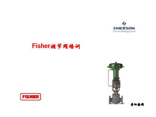
不同的阀笼形状决定了阀门的不同流量特性 以等百分比特性为最优,其调节稳定,调节性能好。
气动调节阀分类:
按流向不同分为:流开和流关(闭) 流开:在阀芯节流处介质流动方向与阀门打开方向相同。 流关:在阀芯节流处介质流动方向与阀门关闭方向相同。
哪些阀需要进行流向选择,
哪些不需要?单密封类的调节阀: 单阀座、高压阀无平衡孔的单密 封套筒阀需进行流量选择(通常 选择流开)。
气动调节阀组成:
调节阀=执行机构+阀体部件 其中,执行机构是调节阀的推 动装置,它按信号压力的大小 产生相应的推力,使推杆产生 相应的位移,从而带动调节阀 的阀芯动作。
数字式阀门定位器 接受阀门行程位置 的反馈,以及供气 压力、执行机构的 气动压力+4~20mA 电信号
80年代末(日本)精小 型调节阀出现,在结构 方面,将单弹簧的气动 薄膜执行机构改为多弹 簧式薄膜执行机构,并 将弹簧直接置于上下膜 盖内,使支架大大地减 小减轻;它的突出特点 是使调节阀的重量和高 度下降30%,流量提高 30%。
(阀座保持架)
(导向套)
(阀座)
(阀芯)
ET、ED型直通套筒阀:高低加疏水调整门
Fisher调节阀结构:直通套筒阀(笼式阀)
填料压盖 缠绕垫 阀芯 阀笼 阀座 阀体
阀杆 上阀盖 (盘根室)
密封环
正作用阀
反作用阀
在阀芯顶部开有平衡孔的叫平衡式套筒阀,
否则是非平衡套筒阀
直通套筒阀(笼式阀)特点:
套筒阀用阀笼内表面导向,用阀笼节流可满足所需流量特性特点如下: 1、阀座通过阀笼、阀盖压紧在阀体上,不采用螺纹连接,安装维修方便。 2、流量特性更改方便:在套同上对称的开有3~6个节流孔, 节流开孔形 状与节流特性有关,通过更换套筒(节流开孔形状)来改变节流阀流量 特性。 3、降噪和降低空化影响。为降低控制阀噪音,可采用降噪阀笼或在阀笼 上开小孔降噪。
费舍尔 299H 系列 减压阀 安装指南说明书

简介本安装指南提供了299H系列调压器的安装、启动和调节的相关说明。
如需获取指导手册副本,请联系您的当地销售办事处或登录查看副本。
关于299H系列调压器的说明和零件列表,可参阅指导手册D102684X012。
关于67C系列仪器供气调压器的说明和零件列表,可参阅指导手册D102601X012。
关于P590系列过滤器的说明和零件列表,可参阅指导手册D101555X012。
关于VSX2型紧急切断装置的说明和零件列表,可参阅指导手册D103695X012。
关于VSX8型紧急切断装置的说明和零件列表,可参阅指导手册D103127X012。
P.E.D.类别本产品可用作以下压力设备指令类别的压力设备的安全附件。
也可按照下表,使用安全可靠的工程惯例 (SEP),在压力设备指令外使用。
关于当前PED版本的信息,请查看技术通告:D103053X012。
产品尺寸类别流体类型DN 40, 50 / NPS 1-1/2, 2I1技术规格可用配置型号299H:指挥器操作式减压调压器,配有指挥器,与执行机构外壳一体化安装。
型号299HR:型号299H配备内部微量放散阀,用于释放因热膨胀导致的轻微过压型号299HS:与型号299H相同,配备VSX2紧急切断阀,提供过压或过压和欠压保护型号299HV:与型号299H相同,配备VSX8紧急切断阀,提供过压或过压和欠压保护。
型号299HSR:与型号299 HS相同,配备内部微量放散阀型号299HVR:与型号299 HV相同,配备内部微量放散阀。
阀体尺寸和端部连接形式见表1进口最大工作压力(1),按孔板尺寸划分6.4 x 9.5 mm / 1/4 x 3/8 in. ...........12.1 bar / 175 psig9.5 mm / 3/8 in. ...........................12.1 bar / 175 psig13 mm / 1/2 in. ............................12.1 bar / 175 psig19 mm / 3/4 in. ............................10.3 bar / 150 psig22 mm / 7/8 in.(3) ............................8.6 bar / 125 psig25 mm / 1 in.(3)...............................6.9 bar / 100 psig30 mm / 1-3/16 in.(3) .........................5.5 bar / 80 psig 最大外壳和紧急出口压力(1)4.5 bar / 66 psig验证试验压力所有压力保持组件已根据指令进行验证试验。
费希尔fisher调压阀

费希尔fisher调压阀费希尔fisher调压阀有⾊⾦属冶炼及压延加⼯业利润同⽐将增长100%。
有⾊⾦属矿采选业利润同⽐将增长70%。
⼯程机械⾏业利润同⽐将增长100%。
造船业利润同⽐将增长100%。
汽车整车业利润同⽐将增长50%。
农业机械⾏业利润同⽐将增长50%。
⽔泥制造业利润同⽐将增长60%。
⼀、产品[⾼灵敏度蒸汽减压阀]的详细资料:产品型号:YG43H/Y型产品名称:⾼灵敏度蒸汽减压阀产品特点:本产品主要⽤于蒸汽管路,适⽤于进⼝压⼒变化⼤,流量变化⼤的蒸汽管路。
⼆、结构特点和⽤处:本系列减压阀属于先导活塞式减压阀。
由主阀和导阀两部分组成。
主阀主要由阀座、主阀盘、活塞、弹簧等零件组成。
导阀主要由阀座、阀瓣、膜⽚、弹簧、调节弹簧等零件组成。
通过调节调节弹簧压⼒设定出⼝压⼒、利⽤膜⽚传感出⼝压⼒变化,通过导阀启闭驱动活塞调节主阀节流部位过流⾯积的⼤⼩,实现减压稳压功能。
本系列产品在普通减压阀基础上做了以下改进,加⼤了活塞⾯积,改变了节流结构,改变了密封形式,改进了导阀结构和调节2、改善了流线分布,降低了噪声。
3、改进了密封⾯结构,延长了密封⾯寿命。
三、主要技术参数和性能指标:公称压⼒(Mpa) 1.0 1.6壳体试验压⼒(Mpa)* 1.5 2.4密封试验压⼒(Mpa) 1.0 1.6最⾼进⼝压⼒(Mpa) 1.0 1.6出⼝压⼒范围(Mpa) 0.04-0.6 0.04-1.0 压⼒特性偏差(Mpa)△Pp2P GB12246-1989流量特性偏差(Mpa)P2G GB12246-1989最⼩压差(Mpa) 0.05 0.07渗漏量GB12245-1989*:壳体试验不包括膜⽚、顶盖四、主要零件材料:零件名称零件材料阀体阀盖底盖WCB阀座阀瓣2Cr13缸套活塞铝铁青铜膜⽚PH15-7Mo活塞环对位聚苯导阀座导阀瓣2Cr13主阀弹簧50CrV A导调主弹簧50CrV A调节弹簧60Si2Mn五、流量系数(Cv):DN 15 20 25 32 40 50 65 80Cv 1 2.5 4 6.5 9 16 25 36 六、⼯洲牌⾼灵敏度蒸汽减压阀YG43H/Y系列连接尺⼨:公称通径DN外形尺⼨连接尺⼨L H H1PN 1.0MPa PN 1.6MPaD K n-ф d C D K n-ф d C15 140 160 65 95 65 414 45 12 95 65 414 45 1 420 140 160 65 1010575 414 551425 150 168 68 11585 414 65 1411585 414 651432 180 185 75 13100 418 78 16 13100 418 78 1 5 5 640 180 185 78 145110 418 85 16145110 418 851650 200 193 88 16125 418 100 1616125 418 1001665 230 208 98 18145 418 120 1818145 418 12080 260 228 117 195160 418 135 18195160 818 1352⼀、结构特点和⽤处:⾼压减压阀属于先导活塞式减压阀。
费希尔调压阀说明书

费希尔调压阀说明书费希尔调压阀是一种技术先进、性能稳定的调节阀,通常用于液体、气体、蒸汽等介质的调节。
本说明书旨在介绍费希尔调压阀的结构、工作原理、安装使用、维护保养等方面的相关知识,以帮助用户正确使用并保障其安全运行。
一、结构简介费希尔调压阀由阀体、阀座、阀瓣、弹簧、阀盖等部件组成。
阀盖上设有调节螺帽和开放、关闭阀门的螺旋杆,通过杆与弹簧连接,使弹簧产生一定的压力。
阀瓣则通过旋转与阀座接触,用于调节介质的流量和压力。
阀座面采用不锈钢材料,能够耐受多种介质的腐蚀。
二、工作原理在正常工作状态下,压力入口通过管道进入阀体内部,由阀瓣调节介质流量、降压,经过阀座后流出调压阀输出口。
当介质压力高于设定值时,弹簧压缩,阀瓣适时关闭,介质流量减小,压力降低。
反之,当介质压力低于设定值时,弹簧伸长,阀瓣逐渐打开,介质流量增大,压力升高。
通过阀体上的调节螺帽,可以调节弹簧压力和阀门开度,实现对介质压力的精确控制和调节。
三、安装使用1.安装前应检查调压阀各部件是否完好,防止阀体内有杂物影响正常工作。
2.安装时应按照调压阀进出口标志和箭头方向正确安装。
3.应注意安装调压阀前后管道的清洁和对接完好,避免介质泄漏。
4.在安装前,应检查弹簧是否适合工作压力,如需要更换,请使用原厂生产的配套弹簧。
5.应注意不要损坏调节螺帽和阀门螺旋杆,避免调节不准确。
四、维护保养1.调压阀定期检查:每1-2个月对调压阀进行检查,观察是否有异常噪声、泄漏等情况,如有则及时处理。
2.清洗:清洗调压阀要用温水或清洁剂对外壳和内部部件进行清洗。
3.故障排除:如调节不准确或存在泄漏等问题,需及时调整或更换相应零件。
通过本说明书的介绍,用户可以了解到费希尔调压阀的结构、工作原理、安装使用和维护保养等方面的知识。
在实际使用中,用户应根据实际情况进行操作,确保调压阀的安全稳定运行。
FISHER减压阀说明
FISHER减压阀说明FISHER是全球财富500强艾默生(Emerson)电气公司Management)旗下的一个品牌其在化工、石油天然气、炼油、工业的自动化领域中居于领先地位。
针对特定的燃气设备行业提供优质的产品和技术、咨询、项目管理和维护服务,美国FISHER燃气设备质量一流、技术先进,是燃气设备行业的技术风向标。
国内的广州赫蒂能源设备有限公司自公司成立以来就与fisher精诚合作,已是fisher产品的代理商,建立了稳固的长期合作关系,及专业的售后服务队伍。
燃气减压阀(gas pressure regulator)俗称调压器,是通过自动改变经减压阀的燃气流量而使出口燃气保持规定压力的设备,通常分为直接作用式和间接作用式两种。
减压阀是一种无论气体的流量和上游压力如何变化,都能保持下游压力稳定的装置。
减压阀应能够:1、将上游压力减低到一个稳定的下游压力;2、当减压阀发生故障时应能够限制下游压力在安全范围内。
液化石油气安全燃烧的一个重要部件,连通在钢瓶和炉具之间.FISHER减压阀不仅能把瓶内的高压石油气变为低压石油气(从980千Pa降至100千Pa左右)而且作为液化石油气安全燃烧的一个重要部件,连通在钢瓶和炉具之间,还能把低压气,稳定在适合炉具安全燃烧的压强范围内.即做到经它输出的石油气,在炉具火孔处的气压,随地随时地比外界大气压值大2940Pa左右,因此实际上减压阀是一种自动稳压装置,通过皮膜伸缩减压运行的工作原理。
FISHER费希尔常用调压器型号:299H,299HS,627-496,627-497,627-498,627-499,627-576,627-577,627-578,627-579,1098-EGR,99,EZR,67CFR,CS400,S200,S300,1301F,1301G,FS-67CH-743,R622H-DGJ,R622-DFF,HSR,95H,95L,133L,133H,98H,98L,289H,289L,289HH,67CFR-226,67CFR-237,67CFR-239,67CFR-600等(详情咨询代理--壹捌零贰柒叁柒陆壹捌肆。
费希尔调压器技术资料
费希尔(F I S H E R)调压器的安装、调试及使用说明第一部分:通用注意事项1安装要求1.1取压管(Controlline/Sensingline):调压器的取压(Presureregistration)分两种:外取压(Externalregistration,简写:ext.)和内取压(Internalregistration,简写:int.)。
(1)为什么有时需要外接下游取压管:调压器通过取压管将出口压力引到膜片的一侧,并与膜片的另一侧的弹簧压力进行比较,以感知调压器出口压力的变化,并做出相应的调节,以保证出口压力的稳定。
如果调压器需要外接(即:外取压)下游(Downstream)取压管,但实际未接上的话,那么,调压器感受到的出口压力将是零,调压器会试图将出口压力提高到弹簧的设定值,结果调压器会一直100%打开,出入口压力接近而无法调压。
(2)取压管的安装:取压管的管径要不小于调压器阀体上的取压接口的尺寸。
如果取压管的长度每增加6.1米,要增加一个尺寸的管径(英制)。
较细的取压管会延迟调压器的反应时间,而且容易使调压器变得不稳定。
3/8″外径的取压管是允许的最细的取压管,具体各种型号调压器的取压管的口径要求见《第三部分:各种型号的具体说明》。
取压点要尽量选择在需要测量的、压力比较平稳的地方,而要远离阀门、弯管等会产生压力波动的地方。
下游取压点最好是在距离调压器出口的6-10倍管径处;如果变径(或截止阀,弯管等)离调压器的出口很近,下游取压点要在距离调压器的入口4倍管径处。
取压点处的取压管要与主管线垂直。
取压管上要安装截止阀,截止阀要使用全通阀。
取压管不能堵塞,否则,会影响正常的取压。
1.2下游管径:在很多情况中,为将流速控制在一定的范围内,或者为了减小下游管线的压力损失,要将调压器下游的管径扩大,而且,尽量使扩径接近调压器的出口。
1.3弹簧腔上的放散口:要指向地面,以免杂质或水进入放散口,使调压器无法放散或正常工作。
美国fisher调节阀基础知识

李阳编辑
气 动 薄 膜 式 执 行 机 构
直 行 程 反 作 用
我分公司fisher调阀均为电动调节阀和气动调节阀。
气动调节阀:气动调节阀就是以压缩空气为动力源,以气缸为执行器, 并借助于电/气阀门定位器、转换器、电磁阀、保位阀等附件驱动阀门, (阀芯阀座相对移动)来实现开关量或比例式调节,接收控制信号: 4—20mA电流信号并将电信号转变为压力信号(由定位器完成或电磁 阀完成)来调节管道介质的流量、压力、温度等各种工艺参数。 气动调节阀优点:结构简单、动作可靠稳定、输出力大、安装维修方便、 价格便宜且防火防爆。缺点:响应时间大、信号不适于远传。 电动调节阀:电动执行机构接收4—20mA电流信号,通过电机的正反 转驱使阀芯阀杆产生相对位移(直行程、角行程)来改变阀芯和阀座 之间的截面积大小,控制管道介质的流量、温度、压力等工艺参数。 电动调节阀优点:动作快、适合远距离传送;节能(只在工作时才消耗 电),环保(无碳排放),安装快捷方便(无需复杂的气动管路和气泵 工作站)。 缺点:结构复杂、推力小、价格贵,适用于防爆要求不太高 及缺乏气源的场合。
气动调节阀分类:
按流向不同分为:流开和流关(闭) 流开:在阀芯节流处介质流动方向与阀门打开方向相同。 流关:在阀芯节流处介质流动方向与阀门关闭方向相同。 哪些阀需要进行流向选择, 哪些不需要?单密封类的调节阀: 单阀座、高压阀无平衡孔的单密 封套筒阀需进行流量选择(通常 选择流开)。 流开、流闭各有利弊:流开型阀 门工作比较稳定,但自洁性和密 封性较差,寿命短。流闭型的阀 寿命长、自洁性和密封性好,但 当阀杆直径小于阀芯直径时稳定 性差。 当冲刷严重或有自洁要求时选择 流闭。两位型快关特性调节阀选 择流闭。
行程限位 推杆O型环 密封轴套 行程标尺 执行机构推杆 单作用、直行程 活塞、弹簧式
FISHER调压器技术

Fisher调压器的工作原理
• Fisher调压器的工作原理基于压力调节和反馈控制。通过改变 调压器内部结构或填充物,可以改变出口压力与进口压力之间 的比例关系,从而实现压力的调节。同时,调压器内部通常装 有压力传感器和控制器,能够实时监测出口压力并调整调节机 构,以保持出口压力的稳定。
对环境温度敏感
Fisher调压器对环境温度有一定的 要求,如果工作环境温度过高或过 低,可能会影响其性能和稳定性。
Fisher调压器的未来发展
01
02
03
智能化
随着智能化技术的发展, Fisher调压器将进一步实 现智能化,提高其自动化 和智能化水平。
高效能
未来Fisher调压器将进一 步优化其性能,提高其调 节精度和响应速度,以满 足更广泛的应用需求。
Fisher调压器还应用于家用空调和制冷设备中,能够调节空 调和制冷设备的压力,提供更加舒适的生活环境。
03 Fisher调压器的优势与挑 战
Fisher调压器的优势
高精度调节
Fisher调压器采用先进的电子控制 技术,能够实现高精度的压力调节,
确保气体或液体的流量稳定。
快速响应
Fisher调压器具有快速的响应能 力,能够快速地适应系统压力的 变化,保证系统的稳定运行。
调压器调节不准确
检查传感器是否正常,如有问题需及 时修复或更换;检查调压器设定值是 否正确,如有问题需重新设定。
05 Fisher调压器的案例分析
工业领域的案例分析
费希尔调压器技术
费希尔(F I S H E R)调压器的安装、调试及使用说明第一部分:通用注意事项1安装要求1.1取压管(Controlline/Sensingline):调压器的取压(Presureregistration)分两种:外取压(Externalregistration,简写:ext.)和内取压(Internalregistration,简写:int.)。
(1)为什么有时需要外接下游取压管:调压器通过取压管将出口压力引到膜片的一侧,并与膜片的另一侧的弹簧压力进行比较,以感知调压器出口压力的变化,并做出相应的调节,以保证出口压力的稳定。
如果调压器需要外接(即:外取压)下游(Downstream)取压管,但实际未接上的话,那么,调压器感受到的出口压力将是零,调压器会试图将出口压力提高到弹簧的设定值,结果调压器会一直100%打开,出入口压力接近而无法调压。
(2)取压管的安装:取压管的管径要不小于调压器阀体上的取压接口的尺寸。
如果取压管的长度每增加6.1米,要增加一个尺寸的管径(英制)。
较细的取压管会延迟调压器的反应时间,而且容易使调压器变得不稳定。
3/8″外径的取压管是允许的最细的取压管,具体各种型号调压器的取压管的口径要求见《第三部分:各种型号的具体说明》。
取压点要尽量选择在需要测量的、压力比较平稳的地方,而要远离阀门、弯管等会产生压力波动的地方。
下游取压点最好是在距离调压器出口的6-10倍管径处;如果变径(或截止阀,弯管等)离调压器的出口很近,下游取压点要在距离调压器的入口4倍管径处。
取压点处的取压管要与主管线垂直。
取压管上要安装截止阀,截止阀要使用全通阀。
取压管不能堵塞,否则,会影响正常的取压。
1.2下游管径:在很多情况中,为将流速控制在一定的范围内,或者为了减小下游管线的压力损失,要将调压器下游的管径扩大,而且,尽量使扩径接近调压器的出口。
1.3弹簧腔上的放散口:要指向地面,以免杂质或水进入放散口,使调压器无法放散或正常工作。
费希尔调压阀说明书

费希尔调压阀说明书篇一:标题: 费希尔调压阀说明书正文:费希尔调压阀是一种广泛应用于各种工业设备和管道上的安全、可靠的调节阀。
它主要用于调节管道中的压力,以达到预定的目标。
本说明书将详细介绍费希尔调压阀的工作原理、使用方法和注意事项。
一、工作原理费希尔调压阀由两个阀门和一个控制器组成。
其中一个阀门是主阀门,另一个是调节阀门。
主阀门和调节阀门之间的连接管道称为调压管。
当需要调节管道中的压力时,可以通过控制调节阀门的开度来调节主阀门的输出流量,从而实现压力的调节。
二、使用方法1. 安装调压阀将调压阀安装在管道上,并确保与管道的连接正确。
安装时需要注意调压阀的密封圈是否磨损,如果有磨损需要更换密封圈。
2. 连接调压管将调压管连接到调压阀的进气管和输出水管上。
连接时需要注意调压管的接口是否正确,管径是否匹配,并确保连接处密封良好。
3. 打开主阀门打开主阀门,使调压管中的水流动起来。
此时,调压阀的控制器将开始工作。
4. 调节调节阀门通过调节调节阀门的开度,可以控制调压管中的压力。
调节时需要注意调节阀门的开度不要过大,以免对管道造成损坏。
5. 关闭主阀门当调节调节阀门的开度达到所需值时,关闭调节阀门。
此时,调压阀的控制器将停止工作。
6. 测试调压效果在使用完调压阀后,需要对调压效果进行测试。
将调压阀关闭,测量调压管中的压力,确保达到预定的目标。
三、注意事项1. 调压阀应安装在管道的适当位置,避免安装在压力过高或过低的区域。
2. 在使用调压阀时,应确保调压管的接口正确,管径匹配,密封良好。
3. 调压阀的控制器应定期检查,确保其正常工作。
4. 在使用调压阀前,应仔细阅读说明书,了解其使用方法和注意事项。
5. 禁止在危险的环境中使用调压阀。
四、总结费希尔调压阀是一种广泛应用于各种工业设备和管道上的安全、可靠的调节阀。
它简单易用,性能稳定,可以有效地调节管道中的压力。
在使用费希尔调压阀时,需要安装正确,注意使用方法和注意事项,并定期检查和维护。
fisher调节阀基础

截止阀的流体阻力较大,适用于需要控制流量和压力的场合。
截止阀的阀体通常采用铸造或锻造工艺制成,具有较高的强度和耐腐蚀性。
03 Fisher调节阀的选型与安 装
选型原则
根据工艺需求
根据管道中介质的性质、流量 、压力等参数,选择适合的调
节阀类型和规格。
考虑流通能力
选择流通能力与工艺需求相匹 配的调节阀,以确保调节阀能 够满足流量调节的要求。
Fisher调节阀基础
目录
• Fisher调节阀简介 • Fisher调节阀的类型 • Fisher调节阀的选型与安装 • Fisher调节阀的故障排除 • Fisher调节阀的发展趋势与未来展望
01 Fisher调节阀简介
定义与特点
易于维护
调节阀结构简单,易于维护和保养。
定义
Fisher调节阀是一种控制流体流量的阀门 ,通过改变阀口开度来调节流量,从而实 现压力、温度等工艺参数的自动控制。
确定控制精度
根据工艺控制精度要求,选择 控制精度高的调节阀,以确保 工艺参数的稳定。
考虑环境因素
根据现场环境条件,如温度、 湿度、压力等,选择适合的调
节阀材料和密封形式。
安装注意事项
确保安装位置合理
调节阀应安装在便于操作和维护的位 置,同时要考虑到管道走向和流体方 向。
保证安装基础稳定
调节阀安装时应确保基础稳定,以避 免因振动或压力波动等因素对调节阀 性能的影响。
01
02
03
化工行业
扩大在精细化工、石油化 工等领域的应用,满足高 精度控制的需求。
环保领域
应用于污水处理、废气处 理等环保工程,实现环保 设备的自动化控制。
能源领域
在核能、风能、太阳能等 领域发挥重要作用,提高 能源利用效率和稳定性。
美国FISHER调压器说明
美国FISHER调压器说明FISHER是全球财富500强艾默生(Emerson)电气公司Management)旗下的一个品牌其在化工、石油天然气、炼油、工业的自动化领域中居于领先地位。
针对特定的燃气设备行业提供优质的产品和技术、咨询、项目管理和维护服务,美国FISHER燃气设备质量一流、技术先进,是燃气设备行业的技术风向标。
国内的广州赫蒂能源设备有限公司自公司成立以来就与fisher精诚合作,已是fisher产品的代理商,建立了稳固的长期合作关系,及专业的售后服务队伍。
燃气调压器(gas pressure regulator)俗称减压阀,是通过自动改变经减压阀的燃气流量而使出口燃气保持规定压力的设备,通常分为直接作用式和间接作用式两种。
减压阀是一种无论气体的流量和上游压力如何变化,都能保持下游压力稳定的装置。
调压器应能够:1、将上游压力减低到一个稳定的下游压力;2、当调压器发生故障时应能够限制下游压力在安全范围内。
液化石油气安全燃烧的一个重要部件,连通在钢瓶和炉具之间.美国FISHER调压器不仅能把瓶内的高压石油气变为低压石油气(从980千Pa降至100千Pa左右)而且作为液化石油气安全燃烧的一个重要部件,连通在钢瓶和炉具之间,还能把低压气,稳定在适合炉具安全燃烧的压强范围内.即做到经它输出的石油气,在炉具火孔处的气压,随地随时地比外界大气压值大2940Pa左右,因此实际上减压阀是一种自动稳压装置,通过皮膜伸缩减压运行的工作原理。
美国FISHER费希尔常用调压器型号:299H,299HS,627-496,627-497,627-498,627-499,627-576,627-577,627-578,627-579,1098-EGR,99,EZR,67CFR,CS400,S200,S300,1301F,1301G,FS-67CH-743,R622H-DGJ,R622-DFF,HSR,95H,95L,133L,133H,98H,98L,289H,289L,289HH,67CFR-226,67CFR-237,67CFR-239,67CFR-600等(详情咨询代理--壹捌零贰柒叁柒陆壹捌肆。
费希尔二级调压阀
费希尔二级调压阀
费希尔二级调压阀是一种用于控制气体或液体压力的装置,广泛应用于各种工业和商业场合。
费希尔(Fisher)是一个知名的工业设备品牌,提供多种类型的阀门、执行器、调压器和仪表解决方案,旨在提高过程可用性,减少工厂维护,并简化合规性。
费希尔的调压阀产品线中,299H系列指挥器作用式减压调压器能够提供可控的压力和流量,适用于分输、工业和商业应用,其中299HS和299HV型号适合需要关断供气的应用。
此外,还有HSRL系列二级调压器,它经过美国保险商实验室(UL)认证,专用于2级液化石油气系统,适合商业应用,能够处理高达2,600,000 BTU/hr或29.27 SCMH的流量。
值得一提的是,费希尔二级调压阀的设计和制造遵循严格的标准,确保了它们在调节压力时的准确性和可靠性。
这些调压阀通常由耐用的材料制成,能够承受恶劣的工作环境和长时间的使用。
用户可以根据自己的具体需求和应用场合选择合适的型号和规格。
- 1、下载文档前请自行甄别文档内容的完整性,平台不提供额外的编辑、内容补充、找答案等附加服务。
- 2、"仅部分预览"的文档,不可在线预览部分如存在完整性等问题,可反馈申请退款(可完整预览的文档不适用该条件!)。
- 3、如文档侵犯您的权益,请联系客服反馈,我们会尽快为您处理(人工客服工作时间:9:00-18:30)。
299H SeriesD 102684X 012Instruction ManualForm 5497October 2011299H Series Pressure Reducing RegulatorsFailure to follow these instructions or to properly install and maintain this equipment could result in an explosion and/or fire causing property damage and personal injury or death.Fisher ® regulators must be installed, operated, and maintained in accordance with federal, state and local codes, rules and regulations, and Emerson Process Management Regulator Technologies, Inc. (Regulator Technologies) instructions.If the regulator vents gas or a leakdevelops in the system, service to the unit may be required. Failure to correct trouble could result in a hazardous condition. Call a gas service person to service the unit. Only a qualified person must install or service the regulator.IntroductionScope of the ManualThis instruction manual provides installation, adjustment and maintenance instructions, and parts ordering information for the 299H Series regulators. Complete instructions and parts lists for the 67C Series filtered pilot supply regulator, and other Fisher equipment are found in separate instruction manuals.DescriptionThe 299H Series pressure reducing regulators provide a broad capacity of controlled pressure ranges and capacities in a wide variety of distribution, industrial, and commercial applications. A 299H Series regulator has a pilot integrally mounted to the actuator casing. The 299H Series regulators can handle inlet pressures up to 175 psi / 12,1 bar depending on orifice size.Figure 1. 299H Series Pressure Reducing RegulatorThe integral token relief on the Types 299HR and 299HSR regulators is located in the pilot and opens to relieve minor overpressure.The Type 299HS provides overpressure or overpressure and underpressure protection by completely shutting off the flow of gas to the downstream system. It comes with a Type VSX-2 slam-shut device which can be configured for Ovepressure Shutoff (OPSO) or Overpressure and Underpressure Shutoff (OPSO/UPSO). The slam-shut device’s actions are independent of the main valve and of variations to the inlet pressure. The Type VSX-2 slam-shut device has internal or external registration. External registration requires a downstream sensing line.W7513299H Series2SpecificationsSpecifications for 299H Series constructions are given below. Some specifications for a given regulator as it originally comes from the factory are stamped on a nameplate located on the actuator upper casing. Available Constructions Type 299H: Pilot-operated pressure reducing r egulator with a pilot integrally mounted to the actuator casing. Type 299HR: A Type 299H with a token internal r elief valve to relieve minor overpressure caused b y thermal expansion. Type 299HS: Same as the Type 299H with a Type VSX-2 slam-shut valve which provides overpressure or overpressure and underpressure protection. Type 299HSR: Same as the Type 299HS with an i nternal token relief valve.Body Size and End Connection Styles See Table 1Maximum Operating Inlet Pressure by Orifice Size (1)1/4 x 3/8-inch / 6,4 x 9,5 mm . . 175 psig / 12,1 bar 3/8-inch / 9,5 mm . . . . . . . . . . . . 175 psig / 12,1 bar 1/2-inch / 13 mm . . . . . . . . . . . . 175 psig / 12,1 bar 3/4-inch / 19 mm . . . . . . . . . . . . . .150 psig / 10,3 bar 7/8-inch / 22 mm (5) . . . . . . . . . . . . . .125 psig / 8,6 bar 1-inch / 25 mm (5) . . . . . . . . . . . . . . 100 psig / 6,9 bar 1-3/16-inch / 30 mm (5) . . . . . . . . . . 80 psig / 5,5 bar Maximum Casing and Emergency Outlet Pressure (1) 66 psig / 4,5 bar Outlet (Control) Pressure Ranges (1)(2) See Table 2Maximum Set Pressure for Type 299HS (1) 16 psig / 1,1 bar Maximum Set Pressure for Slam-Shut Device (1) 23 psig / 1,6 barMinimum and Maximum Trip Pressure Ranges See Table 3Type VSX-2 Sensing Line Connection 1/4 NPTPressure Control Accuracy (Fixed Factor)(PFM) ±1%(3) of absolute control pressureMinimum Differential Pressure For Full Stroke 1.5 psid / 0,10 bar d Control Line Connections 3/4 NPT Temperature Capabilities (1) -20° to 150°F / -29° to 66°C Approximate Weight 21 pounds / 10 kgPressure RegistrationInternal, External, or Dual Registration; see Figure 2Fixed Restriction Sizes 0.044-inch / 1,1 mm, Red (standard gain) 0.071-inch / 1,8 mm, Green (low gain) 0.082-inch / 2,1 mm, Blue (lower gain)Options • Filter (3): A P590 Series filter installed in the pilot supply tubing between main body and pilot • Filtered pilot supply regulator (3)(4): A Type 67CF supply regulator with integral 5 micron Polyethylene filter1. The pressure/temperature limits in this Instruction Manual and any applicable standard or code limitation should not be exceeded.2. For optimum performance, a pilot supply regulator may be installed in the pilot supply tubing between the main valve and pilot.3. A pilot supply regulator or a P590 Series filter (only one may be used, not both) may be ordered with the Type 299H, but not both.4. For inches w.c., use a pilot supply regulator if actual inlet pressure varies more than ±20 psi / ±1,4 bar and published accuracy is required.5. This orifice size is not available for Types 299HS and 299HSR.299H Series3Table 2. Outlet Pressure RangesOUTLET (CONTROL)PRESSURE RANGETYPESPILOT CONTROL SPRING299H299HR, 299HS, and 299HSRPart Number ColorFree Length Wire Diameter Inches w.c.mbar Inchesmm Inches mm 3.5 to 6(1) 5 to 9(1) 7 to 20(1) 16 to 40(1) 9 to 15(1) 12 to 22(1) 17 to 50(1) 40 to 99(1)X X X X X X X X T13707T0012T13589T00121N3112X00121B413727222Black Yellow Unpainted Purple 1.86 2.05 2.18 2.12 47,252,155,453,80.055 0.051 0.075 0.092 1,401,301,902,341 to 3.25 psig 2.75 to 6 psig 5 to 16 psig 14 to 35 psig 30 to 60 psig69 mbar to 0,22 bar 0,19 to 0,41 bar 0,35 to 1,1 bar 0,97 to 2,4 bar 2,1 to 4,1 barX X X X XX X X - - - - - - - -T13593T0012T13671T0012T13600T001219B0432X01219B0432X022Light blue Orange Red Zinc Green2.12 2.40 2.10 2.15 2.7553,861,053,354,669,80.105 0.120 0.142 0.207 0.2252,673,053,615,265,711. Use a pilot supply regulator if actual inlet pressure varies more than ±20 psi / ±1,4 bar and the published accuracy is required.SETPOINT RANGES SLAM-SHUT TYPEFOR USE WITH MAIN VALVESPRING RANGE MINIMUM TO MAXIMUMTRIP PRESSURE TYPE VSX-2SPRING PARTNUMBER SPRING FREE LENGTH SPRING WIREDIAMETER Inches w.c.mbar Inches w.c.mbar Inches mm Inches mm High Pressure TripLP3.5 to 69 to 15 12 to 2530 to 62T14162T00123.1580,00.0671,705 to 912 to 22 3.5 to 69 to 15 20 to 5250 to 129T14163T00123.1580,00.0802,035 to 912 to 22 7 to 2017 to 50 7 to 2017 to 50 1.4 to 3.9 psig97 to 269T14164T00123.1580,00.0912,3116 to 4040 to 99 16 to 4040 to 99 3.8 to 8.7 psig262 to 600T14165T00123.1580,00.1203,051 to 3.25 psig 69 mbar to 0,22 bar 2.75 to 6 psig 0,19 to 0,41 bar 2.75 to 6 psig 0,19 to 0,41 bar 5.8 to 16 psig 400 to 1103T14166T0012 3.15 80,00.138 3,515 to 16 psig 0,35 to 1,1 bar 5 to 16 psig 0,35 to 1,1 bar 11.6 to 23 psig800 to 1586 T14167T0012 3.15 80,00.170 4,32Low Pressure TripLP5 to 912 to 22 2 to 12 5 to 30 T14168T0012 3.15 80,00.043 1,097 to 2017 to 50 7 to 2017 to 50 4 to 3010 to 75T14169T0012 3.1580,00.0551,4016 to 4040 to 99 1 to 3.25 psig 69 mbar to 0,22 bar 0.36 to 2.3 psig 25 to 159T14170T0012 3.15 80,00.067 1,702.75 to 6 psig 0,19 to 0,41 bar 2.75 to 6 psig 0,19 to 0,41 bar 1.5 to 10.8 psig 103 to 745T14171T00123.1580,00.1253,175 to 16 psig0,35 to 1,1 barNote: Other spring combinations are available, please contact your local Sales Office for additional information.Table 1. Body Sizes and End Connection StylesBODY SIZE,NPS / DNBODY MATERIAL AND END CONNECTION STYLECast Iron (For Types 299H and 299HR only)Ductile IronSteel (For Types 299H and 299HR only)1-1/41-1/2NPT NPT- - - -NPT- - - -NPT2 / 50NPT and CL125 FF (1) flangedNPT , CL125 FF and CL250 RF flanged,and PN 10/16 flangedNPT, CL150 RF flanged, andPN 16 flanged1. This flange is available with a face-to-face dimension of 7.5-inches / 190 mm or 10-inches / 254 mm.Table 3. Type VSX-2 High and Low Trip Pressure Ranges4A7272A7272TYPE 299HR (TOKEN RELIEF DETAIL)TOKEN RELIEF CLOSED TOKEN RELIEF OPENFigure 2. 299H Series Operational Schematics5Principle of OperationSince a pilot-operated regulator is constructed of both a pilot and a main valve, do not exceed the maximum inlet pressure shown on the nameplate.Letter keys in this section refer to Figure 2 unless otherwise noted. Fast response and accuracy are made possible by the amplifying effect of the pilot and by the two-path control system. The function of the pilot is to sense change in the controlled pressure and amplify it into a larger change in the loadingpressure. Any changes in outlet pressure act quickly on both the actuator diaphragm and the loading pilot, thus providing the precise pressure control that is characteristic of a two-path control system.Upstream or inlet pressure is utilized as the operating medium, which is reduced through pilot operation to load the main diaphragm chamber. Tubing connects the inlet pressure to the pilot. Downstream or outlet pressure registers underneath the main diaphragm (E) and on top of pilot diaphragm (F). There are three different versions of pressure registration for the 299H Series.Internal registration —Outlet pressure is registered through the throat (J) to the main diaphragm chamber and then through a small port (G) to the top of the pilot diaphragm.External registration —The throat (J) is blocked and a downstream control line is connected to the pilot upper diaphragm chamber or the actuator lower diaphragm chamber. A small port (G) connects the two chambers.Dual registration —The lower main diaphragm chamber registers outlet pressure through the throat (J) and the upper pilot diaphragm chamber registers downstream pressure by using a downstream control line. The port (G) between the chambers is blocked.Type 299HIn operation, assume the outlet pressure is less than the setting of the pilot control spring (A). The top side of pilot diaphragm assembly (F) will have a lower pressure than the setting of the control spring (A). The control spring (A) forces the diaphragm assembly upward, opening the pilot orifice (C). Additional loading pressure is supplied from the pilot orifice to the top side of the main diaphragm (E).E 0072Figure 2. 299H Series Operational Schematics (continued)TYPE 299HSINLET PRESSURE OUTLET PRESSURE ATMOSPHERIC PRESSURE LOADING PRESSURE ATMOSPHERIC PRESSURE LOADING PRESSUREATMOSPHERIC PRESSURE LOADING PRESSURE INLET PRESSUREOUTLET PRESSURE ATMOSPHERIC PRESSURE LOADING PRESSURE299H Series6Once the ball is released, the spring force on the stem will push the stem and disk to the closed position against the seat shutting off all gas flow. The pilot supply pressure is also shut off when the Type VSX-2 is closed. The manual reset has an internal bypass to equalize the reset pressure on either side on the slam-shut disk.Overpressure ProtectionLike most regulators, the Type 299H has outlet pressure ratings lower than the inlet pressure ratings. Complete downstream overpressure protection is needed if the actual inlet pressure exceeds the outlet pressure rating.Overpressure protection for internal parts is builtinto the main and pilot diaphragms by means of a small spring on each post. The springs will allowthe diaphragm heads to move farther on the posts avoiding damage to or bending of the valve trim. Overpressuring any portion of a regulator or associated equipment may cause leakage, parts damage, or personal injury due to bursting of pressure-containing parts or explosion of accumulated gas. Regulator operation within ratings does not preclude the possibility of damage from external sources or from debris in the pipeline. A regulator should be inspected for damage periodically and after any overpressure condition.The pilot vent is provided with a 1/4 NPT tapped connection in the spring case.InstallationPersonal injury, equipment damage, orleakage due to escaping gas or burstingof pressure-containing parts might resultif this regulator is overpressured or isinstalled where service conditions couldexceed the limits for which the regulatorwas designed, or where conditions exceedany ratings of the adjacent piping orpiping connections. To avoid such injuryor damage, provide pressure-relievingor pressure-limiting devices (as requiredby the appropriate code, regulation, orstandard) to prevent service conditionsfrom exceeding those limits.This creates a higher pressure on the top side of the main diaphragm (E) than on the bottom side, forcing the diaphragm downward. This motion is transmitted through a lever, which pulls the valve disk (K) open, allowing inlet pressure to flow through the valve. When the demand in the downstream system has been satisfied, the outlet pressure increases. The increased pressure is transmitted through the downstream control line (for external or dual registration) or through the port (G) (for internal registration) and acts on top of the pilot diaphragm (F). This pressure exceeds the pilot spring setting and forces the diaphragm down, closing the orifice (C). The loading pressure acting on the main diaphragm (E) bleeds to the downstream system through a bleed restriction (H).With a decrease in loading pressure on top of the main diaphragm (E), the main closing spring (B) exerts an upward force on the diaphragm post which is connected to the main diaphragm (E), pulling it upward. This moves the main valve disk (K) toward its seat, decreasing flow to the downstream system. Type 299HRDuring normal operation the Type 299HR performance is identical to the Type 299H. If an overpressure condition occurs, the pilot diaphragm head will separate from the pilot diaphragm post and travel until it contacts the pilot spring case. The movement of the diaphragm head creates a path and a token or small amount of gas will be released.When the overpressure condition ceases, the pilot diaphragm head will return to the diaphragm post, and the regulator will return to normal operation.Type 299HSThe Type VSX-2 slam-shut device on the Type 299HS regulator is a fast acting slam-shut valve which provides overpressure or overpressure and underpressure protection by completely shutting off the flow of gas to the downstream system. The slam-shut module’s actions are independent of the Type 299HS main regulator and of the variations to the inlet pressure. The Type VSX-2 has internal or external registration. External registration requires a downstream sensing line.The slam-shut disk is held in the open position (reset position) by a small ball holding the disk stem. Ifthe pressure below the diaphragm increases (or decreases) reaching the Type VSX-2 setpoint,the diaphragm will travel upwards (or downwards) operating a lever which in turn releases the ball.299H Series7A regulator may vent some gas to the atmosphere in hazardous or flammable gas service. Vented gas might accumulate and cause personal injury, death orproperty damage due to fire or explosion. Vent a regulator in hazardous gas service to a remote, safe location away from air intakes or any hazardous location. Protect the vent line or stack opening against condensation or clogging.If the regulator is exposed to anoverpressure condition, it should beinspected for any damage that may have occurred. Operation below these limits does not preclude the possibility of damage from external sources or from debris in the pipeline.If the Type VSX-2 is exposed to an overpressure condition, it should beinspected for any damage that may have occurred. Operation below these limits does not preclude the possibility of damage from external sources or from debris in the pipeline.Like most regulators, the 299H Series regulators have an outlet pressure rating lower than its inlet pressure rating. Complete downstream overpressure protection is needed if the actual inlet pressure can exceed the regulator outlet pressure rating or the pressure ratings of any downstream equipment. Regulator operation within ratings does not preclude the possibility of damage from external sources or from debris in the lines. A regulator should be inspected for damage periodically and after any overpressure condition.Clean out all pipelines before installation. Check for damage which might have occurred during shipment. Also, check for and remove any dirt or foreign material which may have accumulated in the regulator body.Apply pipe compound to the external pipe threads of threaded bodies, or use suitable line gaskets and good bolting practices with a flanged body. This regulator may be installed in any position desired as long as the flow through the body is in the direction indicated by the arrow on the body. Install a three-valve bypass around the regulator if continuous operation is necessary during maintenance or inspection.Although the standard orientation of the actuator and pilot to the main valve body is as shown in Figure 1, this orientation may be changed in 90° intervals by rotating the actuator lower casing (key 1, Figure 6) and the elbow fitting (key 19) by 90° and then reinstalling the cap screws.T o keep the pilot spring case from being plugged or the spring case from collecting moisture, corrosive chemicals, or other foreign material, the vent must be pointed down, oriented to the lowest possible point on the spring case, or otherwise protected. Vent orientation may be changed by rotating the pilot spring case with respect to the pilot body.To remotely vent the pilot, remove the screwed-in vent assembly (key 27, Figure 5) from the pilot spring case and install obstruction-free tubing or piping into the 1/4 NPT vent tapping. Provide protection on a remote vent by installing a screened vent cap into the remote end of the vent pipe.An upstream pilot supply line is not requiredbecause of the integral pilot supply tubing (key 21, Figure 6). However, as long as the 1/4 NPT tapping in the main valve body is plugged, this tubing may be disconnected from the main valve (key 17) in order to install a pilot supply line from a desired remote location into the pilot.If using a control line, attach the control line from the pilot tap 2 to 3 feet / 0,61 to 0,91 meters downstream of the regulator in a straight run of pipe. If impossible to comply with this recommendation due to the pipe arrangement, it may be better to make the control line tap nearer the regulator outlet rather than downstream of a block valve. Do not make the tap near any elbow, swage, or nipple which might cause turbulence. For optimal performance, use as large of a control line as practical.In many instances, it will be necessary to enlarge the downstream piping to keep flow velocities within good engineering practices. Expand the piping as close to the regulator outlet as possible.Adjustment of the pilot control spring to produce an outlet pressure higher than the upper limit of the outlet pressurerange for that particular spring can cause personal injury or equipment damage due to bursting of pressure-containing parts or the dangerous accumulation of gases if the maximum actuator emergency casing pressure is exceeded. If thedesired outlet pressure is not within the range of the pilot control spring, install a spring of the proper range according to the Maintenance section.299H Series8Each regulator is factory-set for the pressure setting specified on the order. If no setting was specified, the outlet pressure is set midrange of the pilot control spring. In all cases, check the control spring setting to make sure it is correct for the application.Registration ConversionTo convert the 299H Series regulators from one type of registration to another, all that is required is adding or removing screws and O-rings.To change an internal registration regulator to an external registration regulator with a downstream control line, block the two ports in the throat withscrews and O-rings (J in Figure 2). Remove either the 3/4 NPT pipe plug in the pilot casing or the 3/4 NPT pipe plug in the lower casing and add a downstream control line.To convert an external registration regulator to a dual registration regulator, remove the two screws and O-rings (J in Figure 2) from the throat and use a screw and an O-ring to block the port (G in Figure 2) between the lower diaphragm chamber and pilot diaphragm chamber. Remove the 3/4 NPT pipe plug in the pilot lower casing and add a downstream control line.Type VSX-2 Slam-Shut DeviceTo convert the Type VSX-2 from one type ofregistration to another, all that is required is adding or removing a screw and gasket.To change an internal registration Type VSX-2 to an external registration Type VSX-2 with downstream control line, block the body pitot tube with a screw and gasket (keys 10 and 11, Figure 7). Remove the pipe plug in the Type VSX-2 and add a downstream control line.Type VSX-2 InstallationNoteThe Type VSX-2 slam-shut module should be mounted so that the spring case vent points towards the ground.Keys are referenced in Figure 7. Place new O-rings (keys 2 and 3) on the Type VSX-2 and slide themodule into the Type 299HS body (key 17). Secure the Type VSX-2 to the Type 299HS body with the four set screws (key 4). The Type VSX-2 device may be oriented in any direction with respect to the sensor line connection.StartupWith proper installation completed and downstream equipment properly adjusted, perform the following procedure while monitoring the pressure with gauges. 1. Very slowly open the upstream block valve. 2. On a Type 299HS, the Type VSX-2 is shipped in the tripped position and will need to be reset. If the Type VSX-2 is a high trip only, it can be reset before starting the regulator. If the Type VSX-2 is a high and low trip, the regulator will need to be started and the downstream system pressurized before the Type VSX-2 can be reset. See the section for Type VSX-2 reset.3. Slowly open the hand valve (if used) in thecontrol line. The regulator will control downstream pressure at the pilot control spring setting. See the Adjustment section following these numbered steps if changes in the setting are necessary during the start-up procedure.4. Slowly open the downstream block valve.5. Slowly close the bypass valve, if used.6. Check all connections for leaks.AdjustmentKeys are referenced in Figure 4. The only adjustment on a 299H Series regulator is the reduced pressure setting of the pilot control spring (key 32). Remove the closing cap (key 29) and turn the adjusting screw (key 36). Turning the adjusting screw clockwise into the spring case increases the controlled or reduced pressure setting. Turning the screw counterclockwise decreases the reduced pressure setting. Always tighten the locknut (key 35) and replace the closing cap after making adjustments.Type VSX-2 ResetNoteThe overpressure and underpressure trip points can only be reset if theType 299HS outlet pressure is between the overpressure and underpressure trip points.Use the following procedure to reset the Type VSX-2: 1. Unscrew the brass resetting knob to open the equalizing bypass.299H Series92. Pull out the knob until it stops. This resets the tripping mechanism.3. Push in and tighten the knob.Type VSX-2 Trip AdjustmentNoteAn adjustment tool is included with the Type VSX-2 (see Figure 8). Use only this tool to make adjustments to the Type VSX-2. To make adjustments, the overpressure trip spring (key 7, Figure 7) is found under the outer adjusting screw and the underpressure trip spring (key 8) is found under the inner adjusting e the following procedure to adjust the Overpressure Trip Spring:1. Use the Type VSX adjusting tool toadjust the overpressure trip spring to its maximum compression (see Figure 8).2. If present, adjust the underpressure spring(using the Type VSX adjusting tool) to its minimum compression.3. Backpressure the unit with the desired overpressure trip pressure.4. Reduce the overpressure trip spring compression until the Type VSX-2 trips.Use the following procedure to adjust the Underpressure Trip Spring:1. Use the Type VSX adjusting tool to adjust the underpressure trip spring to its minimum compression.2. Backpressure the unit with the desired underpressure trip pressure.3. Increase the underpressure trip spring compression (using the Type VSX adjusting tool) until the Type VSX-2 trips.ShutdownInstallation arrangements may vary, but in any installation it is important to open and close valves slowly and the outlet pressure be vented before venting inlet pressure to prevent damage caused by reverse pressurization of the regulator. Isolate the regulator from the system. Vent the downstream pressure; then vent inlet pressure to release any remaining pressure in the regulator.MaintenanceRegulator parts are subject to normal wear and must be inspected periodically and replaced as necessary. The frequency of inspection and replacement depends upon the severity of service conditions and upon applicable codes and government regulations. Due to the care Regulator T echnologies takes inmeeting all manufacturing requirements (heat treating, dimensional tolerances, etc.), use only replacement parts manufactured or furnished by Regulator T echnologies.Avoid personal injury or damage to property from sudden release of pressure or uncontrolled gas or other process fluid. Before starting to disassemble, carefully release all pressures according to the Shutdown procedure. Use gauges to monitor inlet, loading, and outlet pressures while releasing these pressures.On reassembly of the regulator, it is recommended that a good quality pipe thread sealant be applied to pressure connections and fittings and a good quality lubricant be applied to all O-rings. Also apply an anti-seize compound to the adjusting screw threads and other areas as needed.NoteThe regulator body may remain in the pipeline during maintenance procedures.Main Actuator DiaphragmFollow this procedure to change the actuatordiaphragm, or to inspect, clean, or replace any other parts in the main actuator. Part key numbers are referenced in Figures 5 and 6.1. Cut the wire seal (key 68) (being careful not to lose the warning tag) and remove the closing cap (key 3). Inspect the O-ring (key 9) and replace if necessary.2. Carefully loosen and remove the double nuts(key 5) on the actuator diaphragm post (key 10). When removing the adjusting nuts, do not twist o r unscrew the diaphragm post, as this action will l oosen the joint between the diaphragm post and the pusher post (keys 10 and 11).299H Series103. Remove the spring seat (key 4) and closing spring (key 6).4. Remove the eight hex head cap screws (key 23) and lift off the upper casing (key 2).5. Remove the diaphragm assembly (key 8) bytipping it so that the lever (key 26) slips out of the pusher post (key 11).6. Separate the diaphragm assembly by unscrewing the diaphragm post (key 10) from the pusher post (key 11) and remove the diaphragm post, pressure equalization spring (key 7), diaphragm head (key 81), diaphragm (key 8), the second diaphragm head (key 81), and diaphragm pad (key 80). Inspect the diaphragm parts for damage and replace if necessary.7. Inspect the lever (key 26) and replace ifnecessary. T o replace the valve stem (key 16), also perform Main Body Valve Disk and Orifice maintenance procedure steps 1, 2, and 3, remove disk (key 13), and pull the stem out of thelower casing assembly (key 1). Lightly lubricate the replacement stem O-ring (key 14) and install it on the valve stem. Reinstall the valve steminto the lower casing assembly. Reinstall the body (key 17) or continue with the reassembly of the diaphragm.NoteWhen assembling the diaphragm assembly(keys 8, 80, and 81), lubricate the actuator diaphragm post (key 10) threads.8. Loosely reassemble the diaphragm and diaphragm post parts so that the bolt holes in the diaphragm align with the corresponding holes in the lower casing (key 1) when the lever (key 26) is fittedproperly into the pusher post. When this orientation is made, tighten the diaphragm post into the pusher post (keys 10 and 11).9. Reinstall the diaphragm assembly using the reverse order of step 5.10. Install the upper casing (key 2) and secure it to the lower casing (key 1) with the eight hex head screws (key 23). Tighten the hex head screws evenly using a crisscross pattern to avoid placing an uneven strain on the regulator. Tighten the screws to a final bolt torque of 10 to 13 foot-pounds / 13 to 17 N•m to avoid crushingthe diaphragm.In step 11, the spring seat (key 4) isunder spring pressure. Use constant hand pressure to hold the spring down when installing the hex nuts (key 5), see Figure 5.11. Install the closing spring (key 6) and the spring seat (key 4). Push and hold down on the spring seat, cocking it to one side until the seat catches onto the threads of the diaphragm post (key 10). Then, pull up on the diaphragm post allowing access to the post threads so that the twoadjusting hex nuts (key 5) can be installed. Install the adjusting hex nuts as shown in Figure 5. The closing spring must be adjusted down to a depth of 1/2-inch / 13 mm from the top of the upper case opening to the top of the spring seat. When tightening the two hex nuts, use care not to rotate the diaphragm post, which may damage the post. 12. Lightly lubricate the O-ring (key 9) on the closing cap and reinstall the closing cap (key 3).The wire seal and warning tag (keys 68 and 69) contain important safetyinformation, make sure they are attached when maintenance is completed.13. Install the wire seal and warning tag (keys 68 and 69).Main Body Valve Disk and OrificeFollow this procedure to inspect, clean, or replace the main body valve disk or to inspect or replace the orifice. Part key numbers are referenced in Figures 5 and 6.NoteThe regulator body may remain in the pipeline during maintenance procedures. 1. Disconnect the pilot supply tubing (key 21) from the main body (key 17).2. Remove the two hex head cap screws (key 18) which hold the lower casing (key 1) to the body.。
