HW19710(15710)使用说明书(14.28)
CNHTC· 大同齿轮公司·产品介绍

中国重汽集团大同齿轮有限公司推荐材料大同齿轮有限公司销售部2009年6月尊敬的徐厂长、相关领导:原山西大同齿轮集团有限公司于原山西大同齿轮集团有限公司于原山西大同齿轮集团有限公司于200820082008年年1111月与中国重月与中国重汽进行了重组,重组后更名为中国重汽集团大同齿轮有限公司(以下简称大齿公司),现大齿公司已形成一个覆盖120-420120-420马力的全系列变速箱研发、生产基地,是市场面马力的全系列变速箱研发、生产基地,是市场面向国内、国外客户的重点零部件供应商。
现将重组后的大齿公司战略定位及目前重点推广产品通报如下。
大齿公司战略定位一、大齿公司企业及产品战略定位大齿公司通过跨越式发展,力争在大齿公司通过跨越式发展,力争在大齿公司通过跨越式发展,力争在3-53-53-5年内成为国内齿轮行业最优秀的企业年内成为国内齿轮行业最优秀的企业之一。
大齿公司承担重汽集团内一定比例的生产任务外,将重点保证重汽集团外国大齿公司承担重汽集团内一定比例的生产任务外,将重点保证重汽集团外国内外市场其他用户的需求。
大齿公司的产品生产包括中国重汽主销的大齿公司的产品生产包括中国重汽主销的290290马力以上车型匹配的各款马力以上车型匹配的各款马力以上车型匹配的各款HW HW HW变变速箱,同时也继续生产原大齿公司的速箱,同时也继续生产原大齿公司的DC DC DC系列的变速箱。
系列的变速箱。
二、大齿公司产能规划介于中国重汽变速箱将向全社会开放,目前中国重汽总体变速箱产能按不低介于中国重汽变速箱将向全社会开放,目前中国重汽总体变速箱产能按不低于年生产能力于年生产能力353535万台规划,其中中国重汽变速箱部已经实现万台规划,其中中国重汽变速箱部已经实现1010万台生产能力,基万台生产能力,基本能够保证集团需求。
中国重汽大同齿轮公司将形成中国重汽大同齿轮公司将形成中国重汽大同齿轮公司将形成252525万台生产能力,目前在大同经济开发区将建万台生产能力,目前在大同经济开发区将建设20002000亩的新厂区,在亩的新厂区,在亩的新厂区,在2-32-32-3年内形成年内形成年内形成252525万台生产能力。
海伯核采样器操作手册说明书
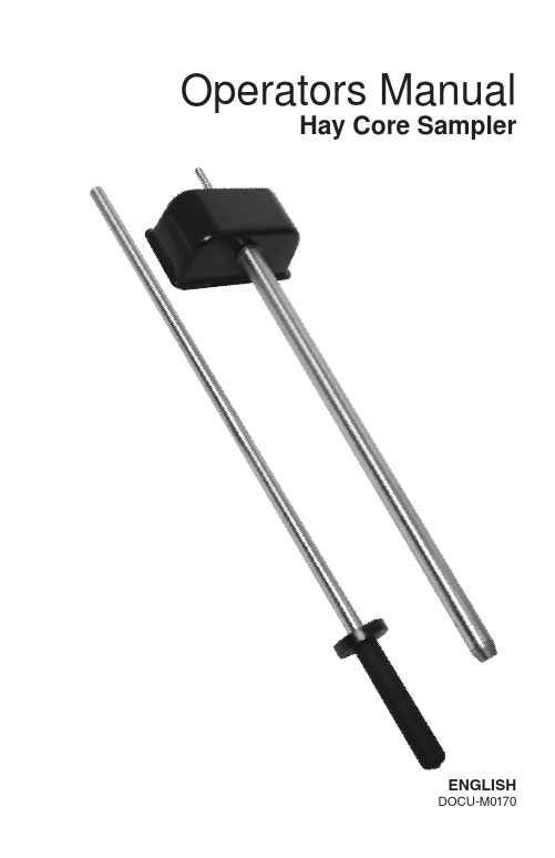
After obtaining enough samples, remove the bag from the steel cup, press the excessive air out from the plastic bag and secure it tightly. Add necessary markings (date, bale, crop, name, number) and store it properly. [cool place with non-fluctuating temperature]
Tests have shown that Hay Core Sampler’s cutting tip stays sharp for about 500 full depth core samples taken from dense round hay bale. You can also use drill to sharpen the cutting tip but use special care when sharpening the tip with the help of drill.
Cleaning and Storage After use clean the hay core sampler with a damp cloth and rub it dry. Store in dry place, preferably inside where the temperature stays above 32°F / 0°C and doesn’t fluctuate much.
USA
Do not wear any loose clothing when using Hay Core Sampler. Be aware that the cutting tip is very sharp, especially when using the cleaning rod. Use the rubber tip cover to protect the user and the tip when not using the item.
威尔指纹消费机使用说明书_龙腾锐达

成都龙腾锐达科技有限公司提供成都龙腾锐达科技有限公司重要声明:手册中涉及到的图片信息以及功能示意图,因产品型号不同,可能与实际产品有所出入,请以实物为准。
随着产品的更新换代或升级,本手册内容将会做相应的修改,公司保留对本手册的内容进行修改的权利,恕不另行通知。
本手册版权属于公司,未经许可不得以任何形式和手段复制或抄袭本手册内容。
衷心感谢您选用消费终端,为保持该设备处于最佳状态,延长使用寿命,在使用前,请仔细阅读本手册。
1)遵守标注在设备上的所有警示;2)远离容易引起电磁干扰或易产生静电的环境;3)使用随机配备的电源适配器和电池;4)不要与大功率或容易引起电压波动的电器设备使用同一交流电源插座;5)避免在阳光直射、靠近热源、油烟、多尘或有腐蚀性气体的地方使用;6)如有液体洒落到机体上,请及时切断电源,并用干布擦拭干净;7)请勿将其它物体从外壳孔隙推入机体内,防止触电或引起短路;8)定期清洁设备外观。
清洁前,关闭电源开关,拔下电源插头,使用微湿的柔软布料擦拭;9)妥善放置电源适配器及电源线,防止电源线被踩踏、拉扯,造成机具跌落损坏;10)每次开机后请检查时钟是否准确,若出现较大偏差(如超过5分钟),需校正时间后才能使用,否则可能会造成数据混乱;11)若长期不使用,请清洁机具,保持机具整洁及干燥,将机具、配件、用户手册等重新放回原包装箱内,在通风干燥的环境中保存。
12)请勿自行拆装本产品,以防止损坏机器、丢失数据、触电或产生其它危险。
如需检修请联系服务商;13)使用过程中,如出现其它异常情况,请详细记录当前设备状态,并与服务商联系。
目录1.11.1 12. 1.234 3.5 4.设备外观及接口说明 ..............................................................................................................7 4.1 74.2 84.3 88 5.10115.1 116.5.212136.1 136.214 6.2.1 14 6.2.2 14 6.2.3 18 6.2.4 206.2.5 21 6.36.2.622 2222 6.46.3.22324 6.4.1 24 6.4.2 25 6.4.3 26 6.4.4 26 6.4.5 28 6.4.6 286.4.7 296.4.83132 附录二:系统提示及处理措施 ............................................................................................................3638 设备开机不启动 ............................................................................................................................38 3839 刷卡提示“无此卡号” ................................................................................................................39 终端设备频繁重启 ........................................................................................................................ 40 如何删除终端数据 ........................................................................................................................ 40 通过网络不能传输数据 ................................................................................................................4041 U 盘操作不成功 ............................................................................................................................41 4242 repair 方式软件升级 .....................................................................................................................421. 前言本终端设备使用电子支付手段及介质,如非接触式ID卡、MF1卡及其兼容卡、CPU卡、RFID-UIM卡、RFID-SIM 卡等代替小额现金、代金券进行支付,适用于各类小额消费场所,如餐厅、售卖点、会所的电子收费。
汽车用轴承规范
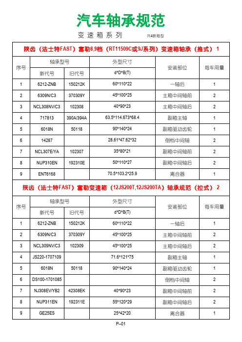
重汽豪沃HW19712TA变速箱用轴承规范
轴承型号 序号 新代号 1 2 3 4 5 6 7 8 9 10 11 12 13 14 15 HW18710T-718改型 HW18710T-717 11*18 K96*104*29.75 K96*104*32.75 K385248 K50703 K909725 P--06 31315X3 SKF4395 32216 33212X3 6317X3N AXK91113 RN6/67/HC 7516E 80*140*35.25 60*110*38 旧代号 主动锥后 主动锥前 二轴后 副轴前后 输出轴轴承 行星架推力 前副箱高档齿轮 行星架前轴向挡圈 行星架后轴向挡圈 销子 外形尺寸 安装部位
一轴后 主箱中间轴前 主箱中间轴后 副箱主轴 副箱驱动齿轮 倒档中间轴 副箱中间轴前 副箱中间轴后 离合器
陕齿(法士特FAST)富勒12档(12JS160T)变速箱轴承(拉式) 3
轴承型号 序号 新代号 1 2 3 4 5 6 7 8 9 6212-ZNB 6309N/C3 NCL308NV/C3 JS220-1707109 6018N 14287 NJ308EV/C3 NUP311EN 42308EK 192311E 50118 旧代号 150212K 370309Y 102308 d*D*B(T) 60*110*22 45*100*25 40*90*23 71.6*121*75 90*140*24 27.61*47.62*32 40*90*23 55*120*29 一轴后 主箱中间轴前 主箱中间轴后 副箱主轴 副箱驱动齿轮 倒档中间轴 副箱中间轴前 副箱中间轴后 离合器 1 2 2 1 1 2 2 2 1 外型尺寸 安装部位 每车用量
重汽豪沃HW90710091065变速箱用轴承规范 6
国产手操器使用说明书

HART 手 持 式 操 作 通 信 器使用说明书目录一、使用说明 (2)二、连接 (2)三、主菜单 (3)四、在线调试状态 (4)1、过程变量 (4)2、附加信息 (5)3、量程修改 (5)4、环路测试 (6)5、线性化 (7)6、压力微调 (9)7、其它 (9)五、装箱清单项 (10)1一、按键操作说明:光标移动键:光标在各项菜单中的上、下、左、右的移动。
字符选择键:只局限在修改数据过程中对数字信息的选取。
确认键:用于各菜单的选取和数字信息的选取。
修改键:用于对仪表的数据信息的修改。
背光键:用于背光的打开与关闭。
电源键:用于电源的打开与关闭。
退出键:用于各项菜单的退出。
功能键:用于扩展功能(待用)。
特定功能键:向上光标移动键:用于在监测“过程变量”中的退出。
二、连接所需仪器:一台智能变送器;一台HART手持式操作通信器(简称:手操器);一台12~45VDC电源;一个大于或等于250欧的负载电阻;一台精密毫安表或毫伏表;一台标准精密压力计(压力计精度至少比变送器高3倍)。
连接如下图所示:23变送器线性化安装图注:为保证可靠通信,请将负载电阻串联在电源的正极。
三、主菜单按下面板中“电源 开/关”按键, 单点通讯将出现HART 手操器主菜单。
如右 轮询通讯图1所示:“单点通讯”在“零号地址码”可使用,若仪表的地址码不为“零号”,则应用“轮询通讯”方式通讯。
菜单中的“ ▋” 为需要选择的 图1 主菜单选项。
按“确认”按键进入在线调试状态(图2)4四、在线调试状态在线调试状态是一个设置的窗口,主要包括七部分组成,如下图2中所示。
可根据用户的需要进行不同的读取与设置。
各个选项的具体操作说明在下面各章节中详细说明。
1、过程变量 如右图3所示。
本选项可以查看仪表的“PV ”(压力)、“I ”(电流)、“PER ”(百分数值)、“T ”(环境温度)、“LRV ”(零位)、“URV ”( 量程)、“LSL ”(最大测量范围低限)、“USL ”(最大测量范围高限)。
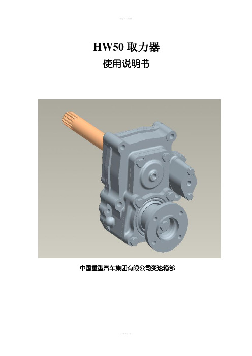
HW50取力器说明书

HW50取力器说明书HW50取力器使用说明书中国重型汽车集团有限公司变速箱部前言中国重汽集团公司HW系列变速器是具有世界先进水平的大功率、多挡位变速器,HW50系列取力器是为配套该系列变速器而开发的新型取力器,该取力器从变速器主箱右副轴取力,适用于匹配HW系列变速器的各类专用车辆,如自卸车、汽车起重机、油罐车、洒水车、散装水泥车等。
中国重型集团公司可根据用户需要,进行产品变型设计、改装配套、技术咨询、维修服务、配件供应等。
警告:HW50取力器正确操作方法:先将变速器操纵杆放在空挡位置,踩下离合,接通取力器开关,待取力器处于挂挡状态,缓缓松开离合,取力器进入工作状态。
本使用说明书的版权和最终解释权归中国重型汽车集团有限公司。
请随时查阅最新版本的使用说明书,如有更改,恕不通知。
HW50系列取力器概述HW50取力器编号规则H W 5 0 (-01)变形号额定输出扭矩的1/10取力器品牌HW50取力器主要性能参数额定输出扭矩500Nm;额定输入转速2600rpm;结构形式:气操纵(单向气缸);输出旋向与发动机旋向:相同;取力器速比:0.74;安装位置:左上角;总速比:HW18709:0.92HW14710/ HW18710 /HW15710/HW19710:0.86HW20716:0.88;HW19710C/HW15710C:0.64工作气压:0.5—0.8Mpa;取力方式:变速器副轴取力;工作温度:小于110?,允许短时间内达到120?。
HW50系列取力器的结构特点及适用范围HW50取力器结构特点:HW50系列取力器为后置取力器,安装于HW系列变速器后部,动力通过取力器花键轴从主箱右中间轴取出,经滑套传给取力器主动齿轮,再经输出齿轮轴、输出法兰将动力输出。
该取力器为单向气操纵,气缸活塞一侧为高压0.5—0.8Mpa,另一侧为回位弹簧。
取力器挂挡后,高压0.5—0.8Mpa接通,高压推动取力器拨叉轴移动,拨叉轴带动拨叉、滑套移动,滑套把输入齿轮和输入齿轮轴连成一体,动力通过输出法兰输出。
HW50取力器说明书
HW50取力器使用说明书中国重型汽车集团有限公司变速箱部前言中国重汽集团公司HW系列变速器是具有世界先进水平的大功率、多挡位变速器,HW50系列取力器是为配套该系列变速器而开发的新型取力器,该取力器从变速器主箱右副轴取力,适用于匹配HW 系列变速器的各类专用车辆,如自卸车、汽车起重机、油罐车、洒水车、散装水泥车等。
中国重型集团公司可根据用户需要,进行产品变型设计、改装配套、技术咨询、维修服务、配件供应等。
警告:HW50取力器正确操作方法:先将变速器操纵杆放在空挡位置,踩下离合,接通取力器开关,待取力器处于挂挡状态,缓缓松开离合,取力器进入工作状态。
本使用说明书的版权和最终解释权归中国重型汽车集团有限公司。
请随时查阅最新版本的使用说明书,如有更改,恕不通知。
HW50系列取力器概述HW50取力器编号规则H W 5 0 (-01)变形号额定输出扭矩的1/10取力器品牌HW50取力器主要性能参数额定输出扭矩500Nm;额定输入转速2600rpm;结构形式:气操纵(单向气缸);输出旋向与发动机旋向:相同;取力器速比:0.74;安装位置:左上角;总速比:HW18709:0.92HW14710/ HW18710 /HW15710/HW19710:0.86HW20716:0.88;HW19710C/HW15710C:0.64工作气压:0.5—0.8Mpa;取力方式:变速器副轴取力;工作温度:小于110°,允许短时间内达到120°。
HW50系列取力器的结构特点及适用范围HW50取力器结构特点:HW50系列取力器为后置取力器,安装于HW系列变速器后部,动力通过取力器花键轴从主箱右中间轴取出,经滑套传给取力器主动齿轮,再经输出齿轮轴、输出法兰将动力输出。
该取力器为单向气操纵,气缸活塞一侧为高压0.5—0.8Mpa,另一侧为回位弹簧。
取力器挂挡后,高压0.5—0.8Mpa接通,高压推动取力器拨叉轴移动,拨叉轴带动拨叉、滑套移动,滑套把输入齿轮和输入齿轮轴连成一体,动力通过输出法兰输出。
国威WSA型程控交换机说明书

目录第一章用户手册简介............................................................................................ 第二章产品概述....................................................................................................2.1产品简介 .........................................................................................................2.2特点.............................................................................................................2.3交换机语音..................................................................................................... 第三章技术要求......................................................................................................3.1技术要求 .........................................................................................................3.1.1容量 ..........................................................................................................3.1.2接口类型 ..................................................................................................3.1.3外设接口 ................................................................. 错误!未定义书签。
最新合勤交换机使用手册

合勤交换机使用手册合勤科技交换机使用手册速查版本 1.0目录1. 硬件连接、常规设置与维护 (3)1.1 硬件安装 (3)1.2 硬件介绍 (3)1.3 常规设置 (5)2. 常规维护 (10)3. 高级设定 (12)3.1 VLAN设定 (12)3.2 STP(生成树协议)设置 (22)3.3 Access Control List (访问控制列表) (26)3.4 ES-3124_ACL功能完成IP与MAC的绑定 (30)3.5 ES-3124_Link Aggregation设置 (34)3.6 IGMP Snooping(组播侦听) (36)3.7 Static MAC Forwarding(静态MAC地址转发) (37)3. 8 Filtering (过滤器) (37)3. 9 Broadcast Storm Control (广播风暴控制) (37)3.10 Mirroring (端口镜像) (38)3.11 DHCP Relay (39)1. 硬件连接、常规设置与维护本章节介绍硬件连接方法,常规设置和基本维护方法,能够帮助您快速安全的将交换机接入网络。
1.1 硬件安装1.1.1 独立式安装:您可以将随机配备的绝缘脚垫安装到交换机底部,并将交换机置放到安全、干燥、清洁的环境中。
图-11.1.2 机架式安装(1)将随机配备的安装部件牢固的固定在交换机两侧。
如下图所示:图-2(2)利用安装部件将交换机牢固的安装在您的机架上。
如下图所示:注释: 合勤科技交换机系列,ES-2024A/ ES-3124/ ES-3148/ GS-2024/ ES-1528/ ES-1552/ GS-1524/ GS-1548都是标准的19英寸长度设计。
图-31.2 硬件介绍合勤交换机前面板的设计大体相似, 左侧是10/100/1000Mbps以太网接口,或者SFP光口。
右侧通常是上联端口,1000Mpbs的以太网接口或者SFP光口,或者是以太网和SFP双重属性端口。
高频式逆变电源说明书

1.3 与电池相关操作的安全防范
1. 如果皮肤、衣物上沾染了电池的酸液,请立即用肥皂和清水清洗。如果酸液 溅入眼睛请立即用冷水冲洗至少 20 分钟并及时就诊。
2. 不要在电池或引擎附近吸烟或制造明火。 3. 不要将金属工具放置于电池上,产生的火花或短路可引发爆炸。 4. 当操作铅酸蓄电池时不要佩戴戒指、手镯、项链、手表等金属饰品,与蓄电
z 具备智能型无人值守功能,在出现直流电压过高或过低、市电掉电等关断输出 后,直流电压或市电恢复正常,电源自动恢复输出,尤其适用于无人值守的通 讯基站;
压。一般红色线接电池组的正极,黑色线接电池组的负极。 务请注意按规定的“+”和“—”极性接入直流母线。 ◆ 安装电池组时,一定要按电池安装说明规定的连接方法和 顺序连接,接线一定要锁紧。禁止将电池的正、负极短路, 禁止同时接触电池的任两接线柱或连接导线的裸露端,否 则可能会导致电池损坏或发生人身伤害。 ◆ 请注意:即使断开市电,逆变电源的内部仍可能有危及人 身安全的高电压。
HW系列变速箱换档操作说明
HW系列变速箱换档操作说明编制:王振保审核:批准:2011年9月HW系列变速箱投放市场以来,因操作不规范造成变速箱自身故障以及引起相关其它故障现象时有发生,最突出的换档操作不规范问题:除起步档使用离合器外,转换其他档位均不使用离合器,直接强行挂档。
这样就对变速箱带来系列影响:极易造成变速箱档位转换困难、异响、打齿、六角键断裂、副箱同步器磨损等等故障,减少了变速箱使用寿命,严重的甚至造成重大人员伤亡事故。
为此变速箱部编制了“HW系列变速箱换档操作规范”,并提出如下要求:1、要求分公司、重汽服务站在用户提车时和强保、维修时进行相关的培训。
2、要求在销售和强保、维修环节上不断提醒用户,对新司机必须进行培训,严格依照车辆使用说明书操作。
3、明确告知用户,对未按车辆使用要求而造成总成及零部件损坏的不予以三包索赔,用户自己承担相应的维修费用。
一、HW系列变速器的使用操作总体要求:司机应当严格依照车辆使用说明书的要求驾驶车辆,挂起步档或倒档时,车需停稳后使用一脚离合挂档,转换其他档位必须使用两脚离合,遇到需转换范围档控制开关时,应预选;变速器请不要在大于15度的坡路上长时间运行,否则会降低变速器的使用寿命;注在减档过程中,两脚离合中间要轰一脚油门,便于减档时实现同步;在下长坡时,尽量不要转换范围档。
二、具体操作规范1. HW19710(C)、HW15710(C)和HW13710(C)系列变速器HW19710(C)、HW15710(C)、HW13710(C)系列变速器是由主箱、副箱两段式结构组成,主箱有5个档,副箱有2个档,一共组成10(5 × 2)个前进档和2个倒档,主传动结构如右图所示,HW13710(C)除外。
HW19710(C)、HW15710(C)、HW13710(C)三系列均用HW10(HW10C)代替,根据HW10(HW10C)变速器的操控机构的特点,讲解起步档(一档)的操作方法依照下文的1)中的操作方法;1到5档范围档停在低档侧,6到10档范围档停在高档侧,均无需转换范围档控制开关,因此1到5档和6到10档的转换可依照1档转2档的操作方法即下文2)中讲解的操作方法;5档转6档、6档转5档均需使用范围档控制开关,依照下文3)中讲解的使用方法。
中国重汽HW变速器培训资料

输入扭矩从1200Nm~ 2300Nm
主箱+副箱的组合式变速器
变速器挡位数 10挡
直接挡 HW13710 HW15710 HW19710
超速挡
备注
12挡
HW19712
HW13710C 可选择铁壳/ 铝壳; HW15710C 可匹配 HW19710C HW50/HW 70整体式/直 HW19712C 联式取力器。
一、HW变速器简介 HW变速器主要技术参数
1 2 3 4 HW13710 14.1 10.65 7.81 5.82 HW13710C 10.52 7.83 5.85 4.35 HW15710 14.28 10.62 7.87 5.87 HW19710 HW15710C 10.73 7.98 5.91 4.38 HW19710C HW19712 15.01 11.67 9.03 7.14 HW19712C 11.8 9.17 7.1 5.61 型号 5 6 7 8 9 10 11 4.32 3.27 2.47 1.81 1.35 1 3.25 2.42 1.8 1.34 1 0.75 4.38 3.27 2.43 1.8 1.34 1 3.29 2.45 1.82 1.35 1 0.75 12 R1 12.67 9.47 13.91 10.45 最大扭矩 最高转速 加油量 rpm L R2 Nm 2.91 1350 2600 13 2.18 1500 2600 13 1500 2600 12 3.18 1900 2600 12 1500 2600 12 2.39 1900 2600 12 3.16 1900 2600 14 2.48 1900 2600 14
HW变速器结构原理:
HW13710 、HW15710、HW19710和HW19712变速器是由主箱、 副箱两段式结构组成, HW13710 、HW15710和HW19710主箱有5个 挡,副箱有2个挡;HW19712变速器主箱有6个挡,副箱有2个挡; HW13710 、HW15710、HW19710和HW19712主变速器为手操纵,副
蓄电池内阻分析仪说明书

免责声明
信息, 对于用户由于未遵守下列条款而造成的 人身安全和财产损失, 本公司仪器将不承担任 何责任。
仪器接地 不可在爆炸性气体 环境使用仪器
为防止电击危险,请连接好电源地线。 不可在易燃易爆气体、 蒸汽或多灰尘的环境下 使用仪器。 在此类环境使用任何电子设备, 都 是对人身安全的冒险。 非专业维护人员不可打开仪器外壳, 以试图维 修仪器。 仪器在关机后一段时间内仍存在未释 放干净的电荷,这可能对人身造成电击危险。
8.SCPI 命令参考................................................................................ 26
8.1 8.2 8.3 8.4 8.5 8.6 8.7 8.8 8.9 8.10 8.11 8.12 8.13 命令串解析 ............................................................................................................................. 26 命令和参数 ............................................................................................................................. 27 命令参考 ................................................................................................................................. 29 DISPLAY 显示子系统 ............................................................................................................... 29 FUNCTION 子系统 .................................................................................................................... 30 COMPARATOR 子系统 .............................................................................................................. 31 TRIGGER 子系统....................................................................................................................... 33 FETCH? 子系统 ........................................................................................................................ 34 CORRECTION 子系统 ................................................................................................................. 34 SYSTEM 子系统 ........................................................................................................................ 34 IDN? 子系统............................................................................................................................ 35 ERROR 子系统 ......................................................................................................................... 35 SAV 子系统 ............................................................................................................................. 35
安装、运行与维护手册 - 3700 型号 - 重力卸荷阀说明书

Model 3700, API Type OH2 / ISO 13709 1st and 2nd Ed. / API 610 8/9/10/11th Ed. 安装、运行与维护手册
1Leabharlann 目录5.2 卸下联轴罩........................................................................... 33 5.3 检查转动............................................................................. 34 5.4 泵和驱动机连接....................................................................... 34
3 产品说明 ......................................................................................................................................................13 3.1 3700 的一般说明...................................................................... 13 3.2 铭牌信息............................................................................. 14
5 试车、起动、运行和关机 ............................................................................................................................. 32 5.1 启动准备............................................................................. 32
西铁城 坚韧系列 平板电脑 使用说明书

ChallengeKeeping America’s freight rail lines running efficiently, safely and securely is critical to our economy. It requires ahighly skilled workforce equipped with reliable tools and technology to get the job done. Buckeye Mountain is a strategic technology advisor to the freight rail industry that helps them deploy technology solutions, including mobile technology.When tasked with making sure their customers had a highly reliable, easy to use and extremely durable technology solution to maintain the detailed records of rail car maintenance performed – as required by industry regulations (AAR) – Buckeye Mountain began investigating the different mobile device options.SolutionToday, over 10 years later, after making their decision to recommend Toughbook mobile solutions, Buckeye Mountain has grown to become a Panasonic certified Toughbook partner for the railroad industry. With Toughbook ruggedmobile tablets and laptops, Buckeye Mountain has empowered their customers to evolve beyond manual record keeping and invoicing and transitioned them to a mobile, digital record keeping solution facilitated by Toughbook rugged mobile devices built to withstand the extreme work conditions of railyards.ResultBy equipping customers with the industry leading rugged mobility solutions on the market, Buckeye Mountain has helped increase the railroads’ cost recovery for repairs made in the railyards, which was a considerable hindrance to regulatory compliance and profitability when invoicing was managed with pen-and-paper.Buckeye Mountain helps modernize the railroad industry with Panasonic Toughbook ® Mobile DevicesCASE STUDY: TRANSPORTATIONMaintaining Critical Freight Transportation Infrastructure With Toughbook Mobile DevicesRail transport has been the backbone of American industry for generations, and what began as a disparate set of wooden-railed, horse-drawn tramroads isnow an intricate, locomotive-powered freight system covering more than 150,000 miles across the country.As modern transportation and technology evolved in tandem, the business of freight transport evolved into a highly- structured and complex industry with significant maintenance, inspection and regulation requirements. Buckeye Mountain, which specializes in railroad technology including the development, deployment and management of hardware, software and wireless solutions, is a full service provider supporting their customers specificallyin the area of rail car maintenance for over 20 years. Serving an elite group of customers including all of North America’s Class 1 railroads, Buckeye Mountain offersa wide breadth of solutions and is deeply involved in all aspects of supporting railroad mobile solutions. As a Panasonic Toughbook certified partner, Buckeye Mountain is able to deliver Toughbook rugged, mobile laptop and tablet solutions that fit the needs of those on the front lines of rail car repair and operations.Based on their deep industry experience, Buckeye Mountain knew standard mobile devices were not an option for the extreme conditions the rail technicians and crews faced. And because their customers looked to them tobe a full service provider, including maintenance of the solution, Buckeye sought a technology provider focused on providing the right solutions and support for customers; not just an off the shelf, standard device. With Toughbook mobility solutions, Buckeye Mountain has been able to help modernize their customers’ outdated pen-and-paper bookkeeping with a digital record-keeping and order processing system.Improving Regulatory Compliance AND Cost RecoveryThe railroad industry is required by AAR (American Association of Railroads) Industry Regulation to inspect and repair freight cars using shared rail lines and maintenance standards that are subject to a byzantine set of more than 3,000 job codes, which are regularly updated and revised. With mobility solutions from Panasonic, these rail car repair specialists are able to keep up-to-date with the rapidly evolving standards, but more importantly, Buckeye Mountain is able to transition customers away from the manually recorded invoicing process. Previously, due to outdated systems and device failure, Buckeye Mountain’s customers frequently lost sometimes over 50% of the repair billing records. With the use of Toughbook devices, they now have substantially better records and greater cost recovery for freight car repairs.With Toughbook mobility solutions, Buckeye Mountain has been ableto help modernize their customers’ outdated pen-and-paper bookkeeping with a digital record-keeping and order processing system.For Buckeye Mountain’s customers, work location presents additional challenges. The railyards, where Buckeye Mountain’s customers perform inspections and repairs, are often located in areas where connectivity options are limited and high interference conditions exist. Because Panasonic builds customized antennas and modules to maximize the wireless performance, Toughbook devices offer exceptional wireless connectivity and a reliabledata-entry platform to help ensure the rail crews work gets done, even in remote locations. Additionally, whether faced with a snow storm in Fargo or extreme heat in Phoenix, rail car repair technicians can count on Toughbook to withstand rugged conditions of all varieties.Buckeye Mountain’s partnership with Panasonic not only allows them to support their customers as a full service provider, but the unique relationship between Panasonic and Buckeye Mountain allows for a direct line of feedback to help improve the solutions Panasonic has become known for. Panasonic designs all mobile devices withthe customer’s need in mind, and its relationships with partners like Buckeye Mountain allow that feedback loop to improve solutions for customers today as well as inform the next generation of rugged mobility.Toughbook devices offer exceptional wireless connectivity and a reliable data-entry platform to ensure the rail crews work gets done, even in remote locations.。
惠灵恩路灯系列说明书
©1997 Whelen Engineering Company Inc.Form No.13217B (060707)A u t o m o t i v e : For warranty information regarding this product, visit /warranty•Proper installation of this product requires the installer to have a good understanding of automotive electronics, systems and procedures.•Whelen Engineering requires the use of waterproof butt splices and/or connectors if that connector could be exposed to moisture.•Any holes, either created or utilized by this product, should be made both air- and watertight using a sealant recommended by your vehicle manufacturer.•Failure to use specified installation parts and/or hardware will void the product warranty.•If mounting this product requires drilling holes, the installer MUST be sure that no vehicle components or other vital parts could be damaged by the drilling process. Check both sides of the mounting surface before drilling begins. Also de-burr the holes and remove any metal shards or remnants. Install grommets into all wire passage holes.•If this manual states that this product may be mounted with suction cups, magnets, tape or Velcro®, clean the mounting surface with a 50/50 mix of isopropyl alcohol and water and dry thoroughly.•Do not install this product or route any wires in the deployment area of your air bag. Equipment mounted or located in the air bag deployment area will damage or reduce the effectiveness of the air bag, or become a projectile that could cause serious personal injury or death. Refer to your vehicle owner’s manual for the air bag deployment area. The User/Installer assumes full responsibility to determine proper mounting location, based on providing ultimate safety to all passengers inside the vehicle.•For this product to operate at optimum efficiency, a good electrical connection to chassis ground must be made. The recommendedprocedure requires the product ground wire to be connected directly to the NEGATIVE (-) battery post (this does not include products that use cigar power cords).•If this product uses a remote device for activation or control, make sure that this device is located in an area that allows both the vehicle and the device to be operated safely in any driving condition.•Do not attempt to activate or control this device in a hazardous driving situation.•This product contains either strobe light(s), halogen light(s), high-intensity LEDs or a combination of these lights. Do not stare directly into these lights. Momentary blindness and/or eye damage could result.•Use only soap and water to clean the outer lens. Use of other chemicals could result in premature lens cracking (crazing) and discoloration. Lenses in this condition have significantly reduced effectiveness and should be replaced immediately. Inspect and operate this product regularly to confirm its proper operation and mounting condition. Do not use a pressure washer to clean this product.•It is recommended that these instructions be stored in a safe place and referred to when performing maintenance and/or reinstallation of this product.•FAILURE TO FOLLOW THESE SAFETY PRECAUTIONS AND INSTRUCTIONS COULD RESULT IN DAMAGE TO THE PRODUCT OR VEHICLE AND/OR SERIOUS INJURY TO YOU AND YOUR PASSENGERS!Warnings to InstallersWhelen’s emergency vehicle warning devices must be properly mounted and wired in order to be effective and safe. Read and follow all of Whelen’s written instructions when installing or using this device. Emergency vehicles are often operated under high speed stressful conditions which must be accounted for when installing all emergency warning devices. Controls should be placed within convenient reach of the operator so that they can operate the system without taking their eyes off the roadway. Emergency warning devices can require high electrical voltages and/or currents. Properly protect and use caution around live electrical connections.Grounding or shorting of electrical connections can cause high current arcing, which can cause personal injury and/or vehicle damage, including fire. Many electronic devices used in emergency vehicles can create or be affected by electromagnetic interference. Therefore, after installation of any electronic device it is necessary to test all electronic equipment simultaneously to insure that they operate free of interference from other components within the vehicle. Never power emergency warning equipment from the same circuit or share the same grounding circuit with radio communication equipment. All devices should be mounted in accordance with the manufacturer’s instructions and securely fastened to vehicle elements of sufficient strength to withstand the forces applied to the device. Driver and/or passenger air bags (SRS) will affect the way equipment should be mounted. This device should be mounted by permanent installation and within the zones specified by the vehicle manufacturer, if any. Any device mounted in the deployment area of an air bag will damage or reduce the effectiveness of the air bag and may damage or dislodge the device. Installer must be sure that this device, its mounting hardware and electrical supply wiring does not interfere with the air bag or the SRS wiring or sensors. Mounting the unit inside the vehicle by a method other than permanent installation is not recommended as unit may become dislodged during swerving; sudden braking or collision. Failure to follow instructions can result in personal injury. Whelen assumes no liability for any loss resulting from the use of this warning device. PROPER INSTALLATION COMBINED WITH OPERATOR TRAINING IN THE PROPER USE OF EMERGENCY WARNING DEVICES IS ESSENTIAL TO INSURE THE SAFETY OF EMERGENCY PERSONNEL AND THE PUBLIC.Warnings to UsersWhelen’s emergency vehicle warning devices are intended to alert other operators and pedestrians to the presence and operation of emergency vehicles and personnel. However, the use of this or any other Whelen emergency warning device does not guarantee that you will have the right-of-way or that other drivers and pedestrians will properly heed an emergency warning signal. Never assume you have the right-of-way. It is your responsibility to proceed safely before entering an intersection, driving against traffic, responding at a high rate of speed, or walking on or around traffic lanes. Emergency vehicle warning devices should be tested on a daily basis to ensure that they operate properly. When in actual use, the operator must ensure that both visual and audible warnings are not blocked by vehicle components (i.e.: open trunks or compartment doors), people, vehicles, or other obstructions. It is the user’s responsibility to understand and obey all laws regarding emergency warning devices. The user should be familiar with all applicable laws and regulations prior to the use of any emergency vehicle warning device. Whelen’s audible warning devices are designed to project sound in a forward direction away from the vehicle occupants. However, because sustained periodic exposure to loud sounds can cause hearing loss, all audible warning devices should be installed and operated in accordance with the standards established by the National Fire Protection Association.Safety FirstThis document provides all the necessary information to allow your Whelen product to be properly and safely installed. Before beginning the installation and/or operation of your new product, the installation technician and operator must read this manual completely. Important information is contained herein that could prevent serious injury or damage.WARNING: This product can expose you to chemicals including Methylene Chloride which is known to the State of California to cause cancer, and Bisphenol A, which is known to the State of California to cause birth defects or other reproductive harm. For more information go to .SL6 Power Supply Kit Retro-Fit Procedures for Edge® models:9004SL/AK 9004WB 9801, 9802,9804, 9804AK, Mini Edge®51 Winthrop RoadChester, Connecticut 06412-0684Phone: (860) 526-9504Internet: Salese-mail:*******************CustomerServicee-mail:*******************®ENGINEERING COMPANY INC.Table of ContentsRetro-Fit guidelines for models (with a ZS or 1ZS, 5ZS or ZSM Power Supply): 9004SL/AK, 9004WB, 9801, 9802, 9804, 9806, Mini Edge®..............................page3 Retro-Fit guidelines for models (with a ZSO, 1ZSO or 2ZSO Power Supply):9004SL/AK, 9004WB, 9801, 9802, 9804, 9806, Mini Edge®..............................page4 SL6 Power Supply and Adaptor Harness Information...................................................page 5 SL6 Specification Table.....................................................................................................page 5 Adaptor Cable Usage Table.............................................................................................. page 52.Locate the “2ZFO/ZF Output Harness Adaptor”shown in Fig. 2 (P/N - 46-0745715-00). This adaptor will be connected to plugs 2 & 3 of the new power supply. NOTE - Make sure that the adaptor harness is installed so that the wire colors of the adaptor plugs are lined up with the wire colors of the power supply’s plugs. 3.With the appropriate adaptor harness plugged onto the new power supply, the new power supply can now be connected to the lightbar. Connect the lightbar’s 4-position power plug to Plug 1. Now locate the harness plugs that were connected to the old power supply and connect to the adaptor harness as follows:Lightbar Plug with:Adaptor Plug with:RED WIRE to RED WIRE WHITE WIRE to WHITE WIRE BLUE WIRE to BLUE WIRE GREEN WIRE toGREEN WIRE4.The new power supply may now be mounted in the lightbar. Position the new power supply in its mounting location. This will be a tight fit and will require a small amount of effort to properly mount the new power supply. NOTE: If harness wraps are present on the old lightbar plug harnesses,it may be necessary to carefully cut and remove these wraps in order for the power supply to fit into the extrusion.5.Secure the power supply to the lightbar using the old power supply’s mounting screws. NOTE:Apply Loctite™ #242 to the threads of each mounting screw.6.Test the lightbar for proper operation. After a successful test, the lightbar may be reassembled in the reverse order in which it was disassembled.7.If the lightbar does not function properly,disconnect the lightbar from its power source, wait 10 minutes to avoid the risk of a high voltage shock and confirm that the proper plugs are connected. If the plugs connections are correct, contact your Whelen representative for further assistance.IMPORTANT NOTE!: SEE PAGE 5 FOR IMPORTANT INFORMATION ON NEW LOW POWER ACTIVATION PROCEDURE.WARNINGThe strobe light power supply is a HIGH VOLTAGEdevice. You must wait at least 10 minutes after turning off the power to the system before starting any diag-nostic or trouble shooting procedures that may bring you into contact with any internal components.9804, 9806, 9004AK, Mini Edge®ZS, 1ZS, 5ZS OR ZSMRemoval of Existing Power Supply...1.Remove endcap and lenses until you have accessto your lightbar’s power supply. Power supply is located in the center section of your lightbar.2.Locate and remove the two screws that hold thepower supply in position and remove the power supply from the lightbar.3.Locate the three harness plugs that connect to theexisting power supply. Before disconnecting these plugs from the power supply, write down each of the the wire colors that were connected to each plug. This is important, as this will determine how these plugs are connected to the new power supply.4.Remove power supply from lightbar. Installation of new Power Supply...1.The new power supply is connected to the lightbarwithout any adaptor cables. When connecting the lightbar plugs to the new power supply, make sure that the wire colors match exactly.2.The new power supply may now be mounted in thelightbar. Position the new power supply in its mounting location. This may be a tight fit and could require a small amount of effort to properly mount the new power supply.NOTE: If harness wraps are present on the old lightbar plug harnesses, it may be necessary to carefully cut and remove these wraps in order for the power supply to fit into the extrusion.3.Secure the power supply to the lightbar using theold power supply’s mounting screws. NOTE: Apply Loctite™ #242 to the threads of each mounting screw.4.Test the lightbar for proper operation. After asuccessful test, the lightbar may be reassembled in the reverse order in which it was disassembled.5.If the lightbar does not function properly,disconnect the lightbar from its power source, wait10 minutes to avoid the risk of a high voltage shockand confirm that the proper plugs are connected. If the plugs connections are correct, contact your Whelen representative for further assistance. IMPORTANT NOTE!: SEE PAGE 5 FOR IMPORTANT INFORMATION ON NEW LOW POWER ACTIVATION PROCEDURE.WARNINGThe strobe light power supply is a HIGH VOLTAGEdevice. You must wait at least 10 minutes after turningoff the power to the system before starting any diag-nostic or trouble shooting procedures that may bringyou into contact with any internal components.9804, 9806, 9004AK, Mini Edge®ZSO, 1ZSO or 2ZSOSPECIFICATIONSINPUT VOLTAGE- 13.5 VDC ±20%INPUT CURRENT OFF- 0 AMPSINPUT CURRENT 30 WATTS - 3 AMPS (TYP)INPUT CURRENT 60 WATTS - 6 AMPS (TYP)INPUT CURRENT 90 WATTS - 9 AMPS (TYP)FLASHRATE (CometFlash®)- 75 FPM (PER LAMP) @ 85 ms FLASHRATE (DOUBLEFLASH)- 110 FPM (PER LAMP) @ 100 ms FLASHRATE (SINGLEFLASH)- 240 FPM (PER LAMP)FLASHRATE (SEQUENTIAL)- 3 CYCLES (COMET) > 4 CYCLES (SF)INPUT CONTROL VOLTAGE - 13.5 VDC ±20%INPUT CONTROL CURRENT - 50 MA (TYP)ENERGY 60 WATT MODE - 26.5 JOULES (TOTAL) 11.5/5/5/5 JOULES ENERGY 90 WATT MODE - 36 JOULES (TOTAL) 15/7/7/7 JOULESENERGY LO POWER MODE- 10 JOULES (TOTAL) 2.5/2.5/2.5/2.5 JOULESFig. 2NOTICEWiring Change:Revision of Low PowerOperationThe Low Power Control Wire (Violet Colored) is now grounded to prevent accidental initiation of the LOW INTENSITY MODE. In order to activate the Low Power Mode:1.Cut the VIOLET wire in the Power Cable.2.Add a length (appropriate size) of 18 AWG wire.3.Connect the additional wire to a Single Pole/Single Throw momentary switch to +12 VoltDC fused@3 Amps.To restore HIGH POWER MODE, turn lightbar off for at least two seconds and then turn the lightbar on.。
海承工业产品:真合气闸树iformation 使用操作及维护指南说明书

INSTALLATION OPERATION & MAINTENANCEOF TRUE UNION AIR RELEASE BALL CHECK VALVES PLEASE READ THE FOLLOWING INFORMATION PRIOR TO INSTALLING AND USING HAYWARD VALVES, STRAINERS, FILTERS, AND OTHER ASSOCIATED PRODUCTS. FAILURE TO FOLLOW THESE INSTRUCTIONS MAY RESULT IN SERIOUS INJURY.1. Hayward guarantees its products against defective material and workmanship only. Hayward assumes no responsibility for damage or injuriesresulting from improper installation, misapplication, or abuse of any product.2. Hayward assumes no responsibility for damage or injury resulting from chemical incompatibility between its products and the process fluids towhich they are subjected. Compatibility charts provided in Hayward literature are based on ambient temperatures of 70F and are for reference only. Customer should always test to determine application suitability.3. Consult Hayward literature to determine operating pressure and temperature limitations before installing any Hayward product. Note that themaximum recommended fluid velocity through any Hayward product is eight feet per second. Higher flow rates can result in possible damage due to the water hammer effect. Also note that maximum operating pressure is dependent upon material selection as well as operating temperature.4. Hayward products are designed primarily for use with non-compressible liquids. They should NEVER be used or tested with compressible fluidssuch as compressed air or nitrogen.5. Systems should always be depressurized and drained prior to installing or maintaining Hayward products.6. Temperature effect on piping systems should always be considered when the systems are initially designed. Piping systems must be designedand supported to prevent excess mechanical loading on Hayward equipment due to system misalignment, weight, shock, vibration, and the effects of thermal expansion and contraction.7. Because PVC and CPVC plastic products become brittle below 40F, Hayward recommends caution in their installation and use below thistemperature.8. Published operating torque requirements are based upon testing of new valves using clean water at 70F. Valve torque is affected by many factorsincluding fluid chemistry, viscosity, flow rate, and temperature. These should be considered when sizing electric or pneumatic actuators.9.Due to differential thermal expansion rates between metal and plastic, transmittal of pipe vibration, and pipe loading forces DIRECTINSTALLATION OF METAL PIPE INTO PLASTIC CONNECTIONS IS NOT RECOMMENDED. Wherever installation of plastic valves into metal piping systems is necessary, it is recommended that at least 10 pipe diameter in length of plastic pipe be installed upstream and downstream of the plastic valve to compensate for the factors mentioned above.SOCKET CONNECTION:Socket end connections are manufactured to ASTM D2467-94. Solvent cementing of socket end connections to pipe should be performed per ASTM specifications D2855-87. Cut pipe square. Chamfer and deburr pipe. Surfaces must be cleaned and free of dirt, moisture, oil and other foreign material. Remove assembly nuts and end connectors from valve body. Slide assembly nuts, with threads facing valve, onto pipe to which the end connector is to be cemented. Apply primer to inside socket surface of end connector. Never allow primer or cement to contact valve ball or end connector o-ring sealing surfaces, as leaking may result. Use a scrubbing motion. Repeat applications may be necessary to soften the surface of the socket. Next, liberally apply primer to the male end of the pipe to the length of the socket depth. Again apply to the socket, without delay apply cement to the pipe while the surface is still wet with primer. Next apply cement lightly, but uniformly to the inside of the socket. Apply a second coat of cement to the pipe, and assemble the end connector to the pipe, rotating the end connector 1/4 turn in one direction as it is slipped to full depth on to the pipe. The end connector should be held in position for approx. 30 seconds to allow the connection to “set”. After assembly wipe off excess cement. Full set time is a minimum of 30 minutes at 60 to 100 F. Full cure time should be based on the chart below.JOINT CURE SCHEDULE:The cure schedules are suggested as guides. They are based on laboratory test data, and should not be taken to be the recommendations of all cement manufacturers. Individual manufacturer’s recommendations for their particular cement should be followed._______________________________________________________________________________________________________Temperature Test Pressures for Pipe Test Pressures for Pipe Test Pressures for Pipe Test Pressures for PipeRange During Sizes 1/2 to 1-1/4 In. Sizes 1-1/2 to 3 In. Sizes 4 to 5 In. Sizes 6 to 8 In _Cure Period(B) Up to Above 180 to Up to Above 180 to Up to Above 180 to Up to Above 180 toºF(ºC) 180 PSI 370 PSI (1240 180 PSI 315 PSI 1240) 180 PSI 315 PSI (1240 180 PSI 315 PSI (1240(1240 kPa) to 2550 kPa) (1240 kPa) to 2170 kPa) (1240 kPa) to 2170 kPa) (1240 kPa) to 2170 kPa)_______________________________________________________________________________________________________60 to 100 (15 to 40) 1 h 6 h 2 h 12 h 6 h 18 h 8 h 24 h40 to 60 ( 5 to 15) 2 h 12 h 4 h 24 h 12 h 36 h 16 h 48 h20 to 40 ( -7 to 5) 6 h 36 h 12 h 72 h 36 h A 4 days A 3 days A 9 days A10 to 20) (-15 to 7) 8 h 48 h 16 h 96 h 72 h A 8 days A 4 days A 12 days AColder than 10 (-15) Extreme care should be exercised on all joints made where pipe, fittings or cement is below 10ºF.A: It is important to note that at temperatures colder than 20ºF on sizes that exceed 3 in., test results indicate that many variables exist in the actual cure rate of the joint. The data expressed in these categories represent only estimated averages. In some cases, cure will be achieved in less time, but isolated test results indicate that even longer periods of cure may be required.B: These cure schedules are based on laboratory test data obtained on Net Fit Joints (NET FIT=in a dry fit the pipe bottoms snugly in the fitting socket without meeting interference).THREADED CONNECTION:Threaded end connections are manufactured to ASTM specifications D2464-88. F437-88 and ANSI B2.1. Wrap threads of pipe with Teflon tape of 3 to 3-1/2 mil thickness. The tape should be wrapped in a clockwise direction starting at the first or second full thread. Overlap each wrap by, 1/2 the width of the tape. The wrap should be applied with sufficient tension to allow the threads of a single wrapped area to show through without cutting the tape. The wrap should continue for the full effective length of the thread. Pipe sizes 2” and greater will not benefit with more than a second wrap, due to the greater thread depth. To provide a leak proof joint, the pipe should be threaded into the end connec tion “hand tight”. Using a strap wrench only. (Never use a stillson type wrench) tighten the joint an additional 1/2 to 1-1/2 turns past hand tight. Tightening beyond thispoint may induce excessive stress that could cause failure.ORIENTATION:As in all plastic piping the maximum fluid velocity is 8 feet per second. This velocity minimizes the effects of valve closure and pump start up or shut down.Note: exhaust flow arrow when installing. The ball is designed to float. When installed as an air release valve the valve should be installed in a vertical position, with the exhaust flow direction arrow pointing up.REPAIR:EXTREME CAUTION MUST BE TAKEN WHEN WORKING ON THIS VALVE.THE PIPING SYSTEM MUST BE DEPRESSURIZED AND DRAINED. PROPER CARE MUST BE TAKEN. CONSULT M.S.D.S. (MATERIAL SAFETY DATA SHEETS) INFORMATION REGARDING YOUR SPECIFIC APPLICATION.Remove the assembly nut and end connector from the “adjust” end of the body, or the complete valve body from the piping sys tem. The front face of the seal retainer indicates which direction of rotation tightens or loosens the seal retainer, with the word “tighten” and a directional arrow, and the word “loosen” and a directional arrow. Direction of rotation may vary depending on date of manufacture.Rotate the seal retainer c ompletely in the “loosen” direction and remove it from valve body. The o-rings and seals are now accessible for replacement using a “seal” repair kit. Carefully remove the o-rings from their respective locations taking care not to scratch their sealing surfaces. Use a non-petroleum base lubricant to lubricate the o-rings, and re-assemble the valve.ABIS Rev B06VS01/19/2001ECR 423S。
- 1、下载文档前请自行甄别文档内容的完整性,平台不提供额外的编辑、内容补充、找答案等附加服务。
- 2、"仅部分预览"的文档,不可在线预览部分如存在完整性等问题,可反馈申请退款(可完整预览的文档不适用该条件!)。
- 3、如文档侵犯您的权益,请联系客服反馈,我们会尽快为您处理(人工客服工作时间:9:00-18:30)。
变速器内应加注85W/90GL-5级车辆齿轮油。
2.正确的油面位置
要确保油面与油面观察口平齐。油面高度由壳体侧面的油面观察口检查,油面注至孔口处出现溢出即可。注油量大约12L(加装取力器时为12.5L)。
3.油面检查
油面高度应定期进行检查,检查油面高度时汽车应停在水平的路面上。由于热油的体积膨胀,为了防止测不准,行驶后的车辆不能立刻检查,只有在油面稳定和油温接近常温时才可进行。
(2)在每根副轴传动齿轮上与齿轮键槽正对的那个齿上打个记号,以便识别。
(3)装配时,使两根副轴传动齿轮上有标记的齿分别啮入输入轴齿轮左右两侧标有记号的两齿之中。
3、换挡机构
HW19710变速器的主箱内没有同步器,换挡是靠移动滑套来进行的,主轴滑套通过渐开线花键套在主轴上,移动滑套使滑套的接合齿(外花键)与主轴齿轮的内花键啮合传递动力,见图7。滑套和主轴各挡齿轮接合齿端有相同大小的锥角:α=35°,由于主轴齿轮相对于主轴处于浮动状态,所以挂挡时,这两个锥面能起到一定的自动定心和同步作用。
注:1、质量中不包括润滑油和离合器分离装置;
2、所指长度为离合器前止口端面到输出法兰端面;
3、()内加油量为加装取力器时的油量。
二、编号规则
HW 197 10 AC-T
前进挡数
系列号,重型变速器系列
扭矩的1%,小于3位同步器……
三、HW19710变速器总成主截面图(见图1)
同时,变速器装有滤清器,以确保到各部位润滑油的清洁。
六、HW19710变速器的拆卸和装配及常见故障和排除
参见维修手册,这里不做介绍。
七、HW19710变速器的使用保养和注意事项
1)使用要求
正确合理地操作使用变速器,定期进行维护保养,对于保证汽车安全可靠的行驶和延长变速器寿命十分重要,请遵循下面使用要求:
一、
HW19710系列变速器主要性能参数
最大输入扭矩:1900Nm
最高输入转速:2600rpm
型号
各挡速比
1
2
3
4
5
6
7
8
9
10
R1
R2
HW19710
14.28
10.62
7.87
5.88
4.38
3.27
2.43
1.80
1.34
1
13.91
3.18
HW19710C
10.73
7.98
5.91
4.38
3.29
副箱采用行星减速结构的优点是传递扭矩大,传动比的范围大,使用寿命长,结构紧凑,能够方便的实现中心轮包括太阳轮和内齿圈的浮动,同时输出轴定位可靠,并且当副箱处于高挡时,行星结构整体绕轴心转动,行星轮只有公转而没有自传,此时行星机构的传动效率几乎是100%,搅油损失小。
2、“对齿”及对齿程序
为了解决双副轴齿轮与主轴齿轮的正确啮合,必须进行“对齿”。
图10
图11
6、取力机构
HW19710变速器采取主箱副轴取力,为后取力,输出旋向与发动机旋向相同。取力器与变速器内腔相通,采用强制润滑,不必另外加注润滑油。
目前,可匹配的取力器有HW50、HW70两系列取力器。
7、变速器的润滑系统
HW19710变速器采用强制润滑和齿轮飞溅润滑相结合的润滑方式,大流量强制润滑油泵使润滑油流到各个部分,使同步器、轴承及齿轮得到充分润滑冷却,见图12。
每行驶50000公里时应更换润滑油。
6.工作温度
变速器在连续工作期间的最高温度不得超过120°C,最低温度不得低于-40°C。工作温度如果超过120°C,会使润滑油分解并缩短变速器使用寿命。
下列情况中的任何一种都能引起变速器的工作温度超过120°C。
<1>连续地在行驶速度<32Km/h的情况下工作。
4.补充润滑油
为了防止不同型号的润滑油发生化学反应,在补充润滑油时应保证与原来的润滑油型号相同。
5.换油周期
变速器在更换润滑油时,要首先将变速器内原有的润滑油放干净,并清洗滤网总成。
新变速器在行驶2000~5000公里时,必须更换润滑油。
每行驶10000公里时应检查润滑油的油面高度和泄漏情况,随时进行补充,并对滤网进行清洗。
目前该变速器适用于功率范围在336~420马力之间的重型车用发动机,是目前国内重型卡车的首选变速器。
本使用说明书的版权和最终解释权归中国重型汽车集团有限公司。
请随时查阅最新版本的使用说明书,如有更改,恕不通知。
警告
◆为避免个人损伤或造成设备故障和损坏,请按指定程序操作变速器;
◆在车辆起动前,驾驶员应坐在驾驶员座位上,将变速杆置于空挡,并使用手刹车;
HW19710系列变速器
使用说明书
中国重型汽车集团有限公司
前言
HW19710变速器是重汽集团公司在数十年技术沉淀的基础上,精心打造的新一代重型汽车专用变速器,该变速器重汽集团公司拥有完全自主知识产权。变速器结构在国内外独树一帜,主箱采用双副轴结构,副箱采用行星减速结构,使承载能力更强,结构可靠。集成的小盖设计使挡位清晰、换挡灵活。
图8图9
5、气操纵系统
气源为两支来自整车的0.7~0.8Mpa的压缩空气。操纵机构气路示意图如图10、图11。后副箱为气操纵,高低挡切换是通过手柄上的预选阀开关实现的。当手柄处在H区,在气控锁止阀和双H阀的作用下整车气源连通变速器气缸下口,范围挡处在高挡区;当手柄处在L区,在气控锁止阀和双H阀的作用下整车气源连通变速器气缸上口,范围挡处在低挡区。当变速器处在挂挡位置时,气控锁止阀实现对手柄阀的锁止作用,手柄阀不能实现高低挡转换。
2.45
1.82
1.35
1
0.75
10.49
2.39
HW15710
14.28
10.62
7.87
5.88
4.38
3.27
2.43
1.80
1.34
1
13.91
3.18
HW15710C
10.73
7.98
5.91
4.38
3.29
2.45
1.82
1.35
1
0.75
10.49
2.39
质量:363kg加油量:12L(12.5L)总长:843mm
◆在车辆进行工作之前或发动机运转时离开驾驶室,应将变速杆置于空挡,并使用手刹车锁死车轮;
◆当停放车辆或离开驾驶室时,应将变速杆置于空挡并使用手刹车;
◆在车辆气压没有升至正确水平情况下千万不要释放手刹车进行换挡操作;
◆变速器处于空挡位置时千万不要长距离滑行;
◆取力器操纵时,按下取力开关后,应立即将离合器踏板踩到底,稍等片刻,取力器正常工作后再松开。
HW19710变速器外部连接尺寸图(见图2)
四、HW19710系列变速器动力传递
参考动力传递线路图(见图3)
HW19710C系列变速器动力传递参考动力传递线路图(见图4)
图4
五、HW19710变速器结构
HW19710变速器是由主箱、副箱两段式结构组成,主箱有5个前进挡,副箱有2个挡,一共组成10个前进挡和2个倒挡。
所谓“对齿”,即组装变速器时,将两根副轴传动齿轮上印有标记的轮齿分别插入输入轴齿轮上印有标记的两组轮齿的齿槽中,见图6。
1-左副轴传动齿轮2-输入轴齿轮3-右副轴传动齿轮
“对齿”程序:
(1)先在输入轴齿轮的任意两个相邻齿上打上记号,然后在与其相对称的另一侧两相邻齿上打上记号。两组记号间的齿数应相等。
如果还是无法挂挡,这时应检查范围挡气缸及其气路,确认哪个部件出现问题,及时修复。
10.“三包”期内的变速器不允许私自拆卸与装配。
1、HW19710变速器主箱、副箱结构,
HW19710变速器主箱结构采用双副轴结构,两根副轴相间180°,副箱采用行星减速机构。动力从输入轴输入后,分流到两根副轴上,然后汇集到主轴,最后通过副箱行星减速机构输出。
在理论上每根副轴只传递1/2的扭矩,所以采用双副轴可以使变速器的中心距及齿轮厚度减小,从而缩短整个变速器的轴向长度,减轻变速器的重量。
为防止这类现象发生,应注意以下几点:
切勿踩下离合器踏板使车辆空挡滑行。
当车辆需要拖行时,可抽出半轴或脱开传动轴,也可以使驱动轮离地拖行。
9.推式离合器轴承润滑
跟随整车保养加注润滑脂,每次注8-10ml;另外,用户可以根据离合器的使用情况,不定期加注润滑脂。
2)注意事项
1.换挡时,离合器必须彻底分离,变速杆应挂挡到位。
5.车辆下坡时,禁止变换高、低挡位区。
6.根据道路情况,采用1挡或2挡起步。
7.车辆起步前,应首先解除制动。采用断气制动的车辆在接通制动阀后,必须待气压上升到解除需要的压力时,方可挂挡起步。
8.使用中发现变速器有异常声响,操作明显沉重等不正常现象应立即停车检查,待排除故障后再继续行驶。
9.该变速器设置有主副箱互锁机构,在副箱未换挡到位时,主箱换挡被锁止,换挡时如果不能挂入挡位,可能是主副箱互锁在起作用,请稍等片刻,再挂挡。
2.换挡手柄开关阀有高挡和低挡两个位置。停车时,开关阀应置于低挡区的空挡位置。
3.车辆挂低挡或倒挡时,应先停车,再挂挡,以免损坏变速器内部的零件。
4.当变速器从低挡区向高挡区(反之亦然)换挡时,应先将开关阀置于H位置,然后摘下挡,有意识在空挡位置稍等片刻,再挂6挡(1挡位置),不要跳挡操作,否则将影响副箱同步器的使用寿命。
<2>发动机转速高。
<3>环境温度高。
<4>涡流环绕变速器。
<5>排气系统太靠近变速器。
<6>大功率超速运转。
7.工作倾斜角
变速器的工作倾斜角超过15°时,润滑可能不充分(工作倾斜角等于变速器在底盘上的安装角加上斜坡角度)。
