英文版智能巡检仪说明书
智能巡检仪说明书
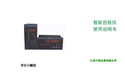
智能巡检仪使用说明书江苏中科仪表有限公司智能巡检仪目一、智能巡检仪表性能特点 (2)二、技术指标 (2)三、仪表参数设置 (5)四、仪表接线方法 (13)概述本系列智能数字巡检仪表采用专用的集成仪表芯片,测量输入及变送输出采用数字校正及自校准技术,测量精确稳定,消除了温漂和时漂引起的测量误差。
本系列仪表采用了表面贴装工艺,并设计了多重保护和隔离设计,并通过EMC电磁兼容性测试,抗干扰能力强、可靠性高,具有很高的性价比。
本系列智能数字巡检仪表具有多类型输入可编程功能,一台仪表可以配接不同的输入信号(热电偶/热电阻/线性电压/线性电流/线性电阻/频率等), 同时显示量程、报警控制等可由用户现场设置,可与各类传感器、变送器配合使用,实现对温度、压力、液位、容量、力等物理量的测量显示、调节、报警控制、数据采集和记录,其适用范围非常广泛。
智能数字显示仪表以双排四位LED显示测量值(PV)和通道值(CH),以双色发光管进行各个通道测量值报警显示,还具有零点和满度修正、冷端补偿、数字滤波、通讯接口、多种报警方式,可选配继电器报警输出,还可选配变送输出,或标准通讯接口(RS485或RS232C)输出等。
一、智能巡检仪性能特点1、专用的集成仪表芯片,具备更为可靠的抗干扰性及稳定性。
2、万能信号输入,通过菜单设置即可配接常用热工信号。
3、可在线菜单修改显示量程、变送输出范围、报警值及报警方式。
4、软、硬件结合的抗干扰模式,有效抑制现场干扰信号。
5、数字化校准技术,无电位器等可调部件。
6、热电偶冷端温度及热电阻引线电阻自动补偿。
7、可分别设置每一通道的测量量程及上下限报警值。
8、具有快速巡检和定点监视功能,巡检时间可设。
9、通过来自输入、输出及电源端的电磁兼容(EMC)测试。
二、技术指标:1、显示方式:双排四位LED显示测量值(PV)和通道号(CH)。
2、显示范围:-1999~9999。
3、测量准确度:±0.2%FS±1字或0.5%FS±1字;±0.1%FS±1字(需特殊订制)。
智能巡检器操作说明书

GS-6000系列巡检器操作说明书(GS-6000B/C/D/E/F)二O一O年七月目录第一章产品组件 (2)1.1 巡检器 (2)1.2 地址信息钮 (2)1.3人名信息钮 (3)1.4 数据下载器 (3)1.5 软件光盘和加密狗 (3)第二章巡检器操作说明 (4)2.1 如何读卡 (4)2.2 关机 (4)2.3 液晶显示内容说明 (4)2.4 技术参数 (5)2.5 数据通讯 (5)2.6 巡检器提示信息 (7)第三章地址钮安装方法 (8)3.1 圆片式地址钮 (8)3.2 管式地址钮 (8)3.3 安装地点的选取原则 (8)3.4 安装注意事项 (8)第四章管理软件安装操作 (9)4.1 软件安装 (9)4.2 数据通讯 (9)4.3 基本信息设置 (9)第五章系统操作中可能遇到的问题 (10)5.1 软件安装完成后找不到巡检器,无法上传数据 (10)5.2 USB驱动已正确安装,还是无法上传数据 (12)5.3 原来可以上传数据,软件系统突然读不了数据了 (13)5.4 巡检器无法读卡 (13)5.5 更换巡检器电池 (14)5.6巡检器系统使用注意事项 (15)第一章 产品组件智能巡检管理系统由巡检器、数据通讯器(数据线或数据通讯座)、地址钮、人名钮和软件光盘组成。
1.1 巡检器应用RFID 射频技术及微型计算机技术设计制造的数据采集记录存贮设备,用于记录巡检人员巡查过的地点、设备和检查时间。
1.1.1 巡检器型号分类1.1.2 巡检器结构说明(见图1)1.2 地址信息钮一种特制的射频电子标签,内部封装有程序芯片控制的感应接收器和一组唯一的十六进制代码。
用于标识巡逻地点、巡查设备、物品名称和人员名称(见图2)。
安装在巡逻签到的地点或巡检设备上。
GS-6000B/D GS-6000C/E GS-6000F图1 巡检器结构说明1.3人名信息钮巡检人员身份牌(见图3),巡逻时先用巡检器读取的身份牌信息,然后去巡逻打卡,巡检器保存的巡逻签到数据按巡检人员姓名保存,并且可以从软件中查询。
英文版智能巡检仪说明书
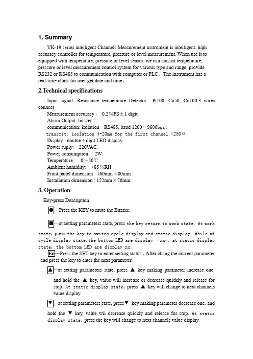
1. SummaryYK-19 series intelligent Channels Measurement instrument is intelligent, high accuracy controller for temperature, pressure or level measurement. When use it to equipped with temperature, pressure or level sensor, we can consist temperature, pressure or level measurement control system for various type and range. provideRS232 or RS485 to communication with computer or PLC。
The instrument has a real-time clock for user get date and time。
2.T echnical specificationsInput signal: Resistance temperature Detector Pt100, Cu50, Cu100,3 wires conncetMeasurement accuracy : 0.2%FS±1 digitAlarm Output: buzzercommunication: isolation RS485, baud 1200~9600bps。
transmit: isolation 4-20mA for the first channel,<250ΩDisplay : double 4 digit LED display.Power suply: 220V AC.Power c onsumption: 2WTemperature: 0~50℃Ambient humidity: <85%RHFront panel dimension : 160mm×80mmInstallation dimension : 152mm×76mm3. OperationKey-press DescriptionPress the KEY to mute the Buzzer.at setting parameters state, press the key return to work state. At workstate, press the key to switch cycle display and static display. While at cycle display state,the bottom LED are display –xx-, at static display。
巡检仪使用说明书(无校准)
如需各通道分别设置报警值并分别对应独立报警接点时,则 CHn+80。
(巡检点数最小为 1,最大为 16,即 CHn 范围为:1-16 或 41-56 或 81-96。)
CHt
通道显示间隔 单位:秒(0.5-50),建议最短时间为 1S。
显示值零点迁移量,例:原显示为 0~1000,当显示位移量设置为 2
注:最高位为 5 时,可进入输出校准菜单,否则其隐藏。(此时修
改 OUT 参数不保存。)当某通道断线或断偶:1)输出方式设为平均、
最大、最小值输出时,则忽略此通道。2)输出方式设为指定通道变送
输出时,本通道输出电流(电压)为 0。
Loo
变送输出零点
如变送输出范围为 0~1000℃,则 Loo=0,Hio=1000。
HIS
显示上限值
1000,则 LoS =0,HIS =1000。Sn=99 时不显示本菜单。
CH-1 1-4 通道测量允许 详见[表三]。
第1页共6页
ANPE 南京优倍电气有限公司
智能巡检仪
CH-5 5-8 通道测量允许
CH-9 9-12 通道测量允许
CH-C 13-16 通道测量允许
AL_C AL1-AL4 报警允许 (XXXX)对应 AL4-AL1,X 为 0 禁止,非 0 允许。
测量范围
00
K
0~1300℃ 13 0-5V
-1999~9999
01
E
0~900℃ 14 1-5V
-1999~9999
02
S
0~1600℃ 15 0-10mA -1999~9999
03
B 300~1800℃ 17 4-20mA -1999~9999
LANDWELL智能巡更巡检管理系统L7000EF使用说明书
LANDWELL智能巡更巡检管理系统L-7000EF型使用说明书美国兰德华LADNWELL(中国)科技投资有限公司北京兰德华电子技术有限公司客户服务电话:目录前言 (2)一.系统分类及型号对照 (3)1.1系统分类及组成 (3)1.2 产品型号对照 (3)二.系统组成及技术特点 (4)2.1中文射频系列 (4)2.1.1 L----7000EF中文射频型 (4)三.系统软件说明 (5)3.1 软件的运行环境 (5)3.2软件的安装 (5)3.3软件使用说明 (5)3.5系统操作步骤 (16)四.系统硬件安装使用说明.................................................................... (19)4.1系统硬件设备的安装 (19)L----7000EF中文射频型 (20)4.3信息钮安装 (25)4.4硬件在软件中的设置 (25)五.系统安装及使用注意事项 (26)六.采集器更换电池注意事项 (26)七.常见故障及解决方案 (26)一、系统分类及型号对照1系统分类及组成.1. 1巡更巡检器:即采集器.巡逻时由巡检员携带, ,按计划设置把信息钮所在的位置,巡更巡检器采集的时间,巡更巡检人员姓名,事件等信息自动记录成一条数据进行分析处理后保存。
再通过传输器把数据导入计算机。
1.2传输线:起到采集器与PC机连接的作用.1.3信息钮(巡检点)-------用于放置在必须巡检的地点或设备上。
1.4软件管理系统-------将有关数据接收分析,并进行处理,提供详尽的巡逻报告,与计划进行对号入座,正确处理巡逻结果数据二、系统组成及技术特点L—7000EF(图) 尺寸: 132×53×25mm重量: 200g材料:合金电源: 2节3V 锂锰并联防爆电池组存储量:12200条内存:4M液晶显示:112*64 国家一二级字库液晶背光:5级背光亮度可调显示界面:人性化的图标和汉字菜单及提示操作温度:-20-+50℃功能: L-7000EF是 L-3000EF扩展产品,双锂电池支持,60毫安的工作电流下,无须连接传输器就可用线传输.具有事件,编程和导航的功能.并可直接在巡检器中查看巡检记录.L—7000ET-(图) 尺寸: 1cm重量: 30g操作温度:-20-+50℃功能: L-7000ET-与计算机通过RS232进行串口通讯,起数据通讯作用。
16,8路巡检仪小说明书
大连鑫飞科技仪表有限公司
0411-66997069
成功 科技创造未来 品质成就 品质成就成功
b.各通道分别设置报警值,共用继电器输出; c.各通道分别设置报警值,独立继电器输出(本方式需配分别报警控制盒); d.各通道独立双色指示灯报警;红色亮表示上限报警,绿色亮表示下限报警; 11、报警精度:±1 字。 12、保护方式:输入回路断线、输入信号超/欠量程报警。 13、设定方式:面板轻触式按键数字设定,设定值断电永久保存。 14、通讯方式:RS232 或 RS485 式可选,采用标准 modbus RTU 协议,通用性强,可靠性高,详见“巡检仪 通讯”。 15、使用环境:环境温度:-10~55℃;环境湿度:10~90%RH。 16、耐压强度: 输入/输出/电源/通讯 ≥1000V.AC /1 分钟。 17、绝缘阻抗: 输入/输出/电源/通讯 ≥100MΩ。 18、电 19、功 源::交流 85~265V,频率: 50Hz/60Hz; 直流:DC 16~32V。 耗:<5W。
HIS
显示上限值
CH_1
1-4 通道 巡检控制
b.当 X > 3 时,表示禁止该通道测量、显示、报警; 例. CH_1=3421,表示第 1 通道显示带 1 位小数点,第 2 通道显示带 2 位小数点, 第 3 通道关闭,第 4 通道显示带 3 位小数点。 注:在各通道统一设置输入类型、显示范围、报警值时,小数点位置由主菜单中 dPS 参数决 定。
大连鑫飞科技仪表有限公司
三、仪表参数设置: 1、 仪表面板定义
0411-66997069
成功 科技创造未来 品质成就 品质成就成功
智能巡检仪
通道显示窗 测量时显示通道 参数设定时显示 参数代码 通道报警指示灯
SLIH1-1A 壁挂式智能温度巡检仪操作手册说明书

SLIH1-1A壁挂式智能温度巡检仪操作手册目录一、引言 (3)二、技术参数及特点 (3)三、典型方案 (4)最简应用方案 (4)无线应用方案 (4)四、接口说明 (5)五、操作说明 (6)1.读入新的传感器(设置密码为1234) (7)2.设置上限报警值(设置密码为1244) (7)3.设置通道是否显示(设置密码为1254) (7)六、通讯协议 (7)查询数据 (8)读出所有通道传感器序列号 (8)七、随机清单 (11)八、订货及备注 (11)一、引言SLHT-1A智能温度数据在线监测仪,配合美国DALLAS一线现场总线技术,实现低成本温度状态在线监测方案的实用型仪器,可广泛应用于实时温度数据采集监测的各种应用场合。
SLHT-1A智能温度数据在线监测仪可以对DS1820数字温度传感器系列产品进行温度数据采集,显示、报警设定,数据传输,使温度巡迴检测系统获得高可靠性、低成本和最简单的布线结构。
作为传统测温系统的理想替代品,其有体积小、测点多、组网灵活等特点。
配合无线或GPRS 及现场单总线传输(1-wire)技术,可以将把分散在各处的DS1820节点通过有线或无线的方式与监控中心联接起来,达到降低能耗、促进安全生产的目的。
本仪器可应(1)SMT行业温度数据监控 (2) 电子设备厂温度数据监控(3) 冷藏库温度监测(4) 仓库温度监测 (5) 药厂GMP监测系统(6) 环境温度监控(7)电信机房监控(8) 电厂/电站机组(9) 电厂/电站机组(10)过程温度监测(11) 啤酒生产过程温度检测等。
为便于工程组网使用,本仪器提供二次开发的通讯协议,支持二次开发。
用户只需根据我们的通讯协议即可使用任何串口通讯软件实现仪器数据的查询和设置。
二、技术参数支持传感器SLST1系列防护型数字温度传感器,DS1820显示测温范围-55℃~+125℃显示分辨率0.1℃测温精度0.5℃测温速度 850ms/点通道数单总线可接1-24点 (限单总线传感器)报警设置在线设定报警上、下限波特率19200 (可订制其它波特率)通讯端口RS232(可选配CAN、RS485)供电电源DC 5V 2A耗电2W重量500克存储温度-40 - 85℃运行环境:-40 - 85℃-40℃~+85℃支持测温电缆长度≤200M外形尺寸200×70×175mm³三、典型方案最简应用方案SLHT-1A仪器可直接通过RS232接口与电脑或笔记连接(可选配RS232-USB转换器)将现场的数据直接传送到电脑进行显示、分析和存储。
巡检仪TRAK-IT使用操作规程
燃气泄漏巡检仪TRAK-IT使用操作规程T R A K-I T系列燃气泄漏巡检仪,配给指定的传感器后,可用来探测可燃气体、氧气含量、有毒气体等,每种T R A K-I T系列摸块提供不同的探测性能,所以的气体用内部吸气泵持续采样,能较好的测量易燃气体的百分比浓度,是一种广泛使用较先进的测量仪器。
一、使用范围采用先进的低功率半导体传感器测量气体的低爆炸极限,采用先进的热传导传敢器测量易燃气体的体积百分比,适用于可燃气体、氧气含量、有毒气体的浓度检测。
二、操作规程警告:任何时候打开T R A K-Ⅲ,都应该在远离可燃气体的环境中,以确保仪器彻底清零。
1、按下“POWER”按钮(电源开关)开始操作,将听到一声短促的提示音。
2、如果没有显示或“BAT LOW”出现在屏幕上,则要替换电池。
3、如果仪器启动正常,吸气泵将起动,显示屏将变亮。
仪器接着依次显示:a.产品名和数字译本。
b.系统检查特有的电池的泵操作。
c.日期和时间。
d.仪器的序列号码。
e.显示“CAL PAST DUE”时,传感器已经超过校准失效,可能需要校准。
警报后预热过程将继续进行。
f.预热倒数计时10秒。
g.显示“AUTO ZERO”调零所有传感器。
h.启动过程中,一些传感器如果完全不能恢复,将显示“FAIL”在探测器的显示屏幕上。
绿色状态指示灯将长亮指示仪器需要维修。
(i.显示所有可用的读数,显示“X”表示没有安装该传感器)。
4、显示屏将通过显示“L”指示LEL读数以过渡到体积百分比显示。
所有的LEL读数的分辨率为0.1%LEL或50ppm甲烷。
当气体浓度超过LEL量程,将不再显示“L”读数。
将显示百分号“%”和气体类型,仪器校准通过显示“N”表示天然气或“P”表示丙烷气。
如果仪器设定为百分比气体浓度读数,则“%”和“N”或“P”是任何时间将仍然显示。
量程为0~2.5%气体时,显示分辨率为0.01%,所有读数大于2.5%的气体浓度显示值的分辨率为0.1%。
ELL8-80路巡检仪说明书

厦门恩莱自动化科技有限公司目录1、概述 (1)2、型号规格 (2)3、技术规格 (3)4、安装与接线 (5)5、前面板及功能操作 (9)5.1 前面板 (9)5.2 功能操作 (10)6、参数设置 (11)6.1 设置报警值 (11)6.2 设置公用组态参数 (12)6.3 设置打印参数 (15)6.4 设置各通道组态参数 (17)7、功能及相应参数说明 (18)7.1 输入信号及显示 (18)7.2 零点和满度修正 (20)7.3 冷端补偿 (21)7.4 报警 (21)7.5 控制单元 (23)7.6 打印 (24)7.7 通信 (25)概述1、概述ELL系列智能巡回检测报警仪适用于5~80点过程量的检测和报警。
可输入热电阻、热电偶、直流电流、直流电压等传感器、变送器信号。
基本误差小于0.2%F·S,显示范围-1999~9999各通道独立设定输入信号类型、量程、报警值各通道独立设定数字滤波时间常数,有效提高抗干扰能力各通道独立设定零点和满度修正,有效减小传感器误差,提高系统测量精度可任意关闭不使用的通道2级参数。
第2级参数受密码控制,防止误操作。
具备参数复制功能,大大减小参数设置的工作量独特实用的报警功能,可配接ELLCU多点控制单元实现各通道的报警输出手动、定时、报警启动打印快速、高效的通信接口,大大缩短通信时间1型号规格2 2、型号规格ELL / ☐— ☐ ☐ ☐ S ☐ P ☐ V ☐ ☐ ☐ ☐1:尺寸A :横式160×84×182 开孔152+1×76+1(宽×高)B :竖式84×160×182 开孔76+1×152+1(宽×高)C :方形160×160×182 开孔152-0.5×152-0.5D :台式,盘装通用318×104×300 开孔312+1×96+1(宽×高)2:通道数 3:输入信号R :全部通道均为热电阻仪表内装的分度号包括:Pt100,Cu100,Cu50,BA1,BA2,G53E :全部通道均为热电偶仪表内装的分度号包括:K ,S ,R ,B ,N ,E ,J ,TB :全部通道均为4mA~20mA 或1V~5V 等电流、电压信号,需在订货时明确电流,电压信号的输入通道X :输入为热电阻、热电偶混用。
智能实时巡检仪说明书

声明:本说明手册只针对“智能实时巡检仪”推送事件信息到“上海巡检平台”,“智能安防集成服务设备”,智能安防集成应用系统上的操作方法。
“实时巡检仪”与“上海巡检平台”的具体使用操作方法,请参考对应的操作手册。
一:实时巡检仪绑定“巡检云平台”的操作方法1.1: 首先需要在“智能实时电子巡检”平台、绑定启用“智能实时巡检仪”的ID,巡检仪ID查看方法如下图:1.2:前往“智能实时巡检云平台“绑定巡检仪设备ID。
(云平台地址:/cgi-bin/patrol/)平台绑定步骤如下图:在IE浏览器内输入云平台地址、在跳出的登陆页面输入账号与密码(如上图),账号与密码标识在巡检仪外包装标签上。
登录成功后,选择“巡更管理“下拉菜单内的”设备管理“。
(如上图)备名称与备注信息根据需要自行任意命名。
如上图二:实时巡检添加进“智能安防集成服务设备”的操作方法(即Agbox)2.1:添加巡检仪之前需要先确保“智能安防集成服务设备”能够连通外网,没连通外网将无法收到巡检仪的推送信息。
测试“智能安防集成服务设备”是否联网方法如下图“登录Agbox之后,选择右边的“系统配置”在下拉菜单内选择“同步事件字典”,在跳出的页面内查看,如果同步内容下有各模块信息出现即表示已经联网,如果没有任何信息显示即表示无外网连接。
如上图2.2:智能安防集成服务设备添加实时巡检仪方法如下:1:在IE浏览器地址栏输入Agbox的地址,在登录界面输入账号即密码登录即可。
默认账号:admin 密码:1234562:点击“实有安防设施”。
3:在下拉菜单内选择“实时电子巡检”模块。
4:在“实时电子巡检”模块下单击鼠标右键,然后选择“添加设备”。
5:在跳出的属性栏内填写相应信息,设备编号处填写“智能实时巡检仪的设备ID”,其余信息根据需要自行填写。
(巡检仪的设备ID查看方法前面已有)6:信息填写完成点击“保存”即可。
2.3:测试“实时巡检云平台”推送事件是否正常具体操作步骤如下:1:首先查看巡检仪与云平台通信是否正常,事件推送是否正常,查看设置方法如下图:在巡检云平台的单位设置页面,必须设置Agbox的区域编码与所属行业的选择。
智能巡检管理系统Tiger V2.0使用说明书
前言感谢您使用本公司的“智能巡检管理系统”。
本手册适用于:智能巡检管理系统Tiger V2.0版郑重声明如下:1、未经本公司许可,本手册及软件的任何部分不得以任何方式复制或抄袭。
2、因使用不当引起的损失,本公司概不承担任何责任。
为了您能正确地设置和使用本系统并得到最佳性能,保证长期使用,请必须仔细阅《智能巡检管理系统软件使用说明书》3、因技术发展需要,本公司保留未经通告而变更本手册、软件及硬件产品性能指标的权利。
4、使用时请注意爱护产品,这是延长其寿命的最好方法。
巡检软件设置简要说明图示第一章智能巡检管理系统概述1.1简介随着社会的进步与发展,各行业对其管理工作的要求越来越规范化、科学化。
各单位对定期定点进行维护、检测人员的责任心的要求也越来越高。
及时消除隐患、防患于未然是每一位企业领导、管理者的希望。
智能巡检管理系统是由我公司引进最新的技术将信息采集技术与计算机技术紧密结合,适应各类巡检情形的巡检系统。
该系统极大地提高了各类巡检工作的规范化及科学化水平,杜绝了对巡检人员和被巡检对象无法科学、准确考核与监控的现象,有效地保障了被巡检设施经常处于良好状态。
1.2运作过程1、连接硬件设备,并给巡检器校时保持与电脑时间一至;2、将信息钮安装在需要巡检的地点;3、按实际工作需要确定巡检线路,并在软件中作相应的设置;4、确定每条巡检线路中的巡检地点,可规定停留时间;5、确定巡检人员;6、确定每条巡检线路中所使用的巡检器号码;7、按月份确定每条巡检线路的巡检计划时间段及相应的巡检人员;8、如果使用感应式巡检器还要确定状态(事件)代码所代表的信息描述。
9、基础设置备份;1.3工作过程根据要求的时间段、巡检地点,工作人员沿指定的线路行进巡检,每到一处,在巡检的同时,用巡检器识读安装在该地的信息钮(或感应器)。
识读时,巡检器会自动记录当前的地点(钮号或卡号)、日期和时间,如有停留时间要求,则应按规定停留时间再次读取。
XWD温度巡检仪使用说明书

XWD系列智能型巡检仪重庆华源水电技术工程有限公司一、 概述XWD智能型巡检仪是以微处理器为核心设计,并广泛吸收了国内外同类产品的各种优点。
具有自校零、自校量程功能,免去用户校正仪表之苦。
仪表的关键器件采用美国INTEL公司、ATMEL公司、MAXIM公司等公司产品,在干扰防护上采用阻容滤波网络,有源滤波,软件滤波等多种抗干扰措施,使得仪表有很强的抗干扰能力。
二、 主要特点1、每个通道的输入信号种类,起始测量值和终止测量值,小数点显示位置可通过面板任意设定,对热电阻输入的品种,可混合使用二线制、三线制。
2、各通道可以独立设置上、下限报警方式、报警值。
3、如果该测量通道不用,可以通过设置取消,如果想要恢复也可设置恢复。
4、软件设置、软件校正,机内无任何调整电位器抗震性好。
5、可带RS-232、RS-485、RS-422等串口与主叫方通讯,也可带4-20mA等标准直流电信号输出。
6、完善的程序监控电路,电压监测保护电路,以多重冗余技术,确保仪表稳定运行。
三、 产品型号及意义说明:1、直流电信号输出只能通过面板设置某一点带输出或者巡检到的点(面板显示的点)有输出。
2、本仪表带2个继电器输出,2个继电器的报警方式可以任意设定。
3、仪表分三类:a、热电偶输入型。
b、热电阻输入型。
c、其它输入。
仪表输入信号在同一类中可以任意设定。
四、 主要技术指标1、检测通道:4-64点2、精度:0.5级3、报警设定范围:全量程4、巡检速度:1-255秒(指面板显示巡检速度)5、输入阻抗:热电偶输入大于1MΩ; 4-20mA小于等于250Ω6、输入信号及测量范围见表17、外线电阻:热电偶输入不大于1KΩ;热电阻输入不大于50Ω8、调节方式:位式调节9、继电器触点容量:交流无感负载220V/3A10、输出(可选):(1)直流电信号输出(2)微机串口输出(RS-232C、RS-485、RS-422)11、冷端补偿范围:0-50O C12、冷端补偿元件:Cu50(铜热电阻)13、使用环境:环境温度:0-50O C;环境湿度:≤85%;大气压:86-108Kpa14、功耗不大于5W15外形尺寸:长×宽×高=160×160×80mm表一:输入类型、测量范围及编码输入信号 代码 测量范围 分辨力K 00 0-1300O C 1 O CE 01 0-800O C 1 O C2.“设置”键:当仪表处于测量状态时,按动此键,仪表就转入设定状态,当仪表处于设定状态时,按动此键,仪表功能会自动转换(具体使用,详看后面的参数设定)。
巡更记录仪说明书

Registrador Computarizado para Control de RondasGracias por haber elegido nuestros productos para realizar el control de vigilancia de su empresa o establecimiento. Esperamos que satisfagan totalmente sus necesidades y le permitan a Ud. ahorrarle tiempo y dinero. Recomendamos la lectura detallada y cuidadosa de este manual antes de la instalación de su Registrador ya que encontrará todo lo necesario para su correcta utilización y notas que lo ayudarán a no correr riesgos que pudieran dañar a su nuevo Registrador Computarizado para Control de Rondas.IntroducciónEste sistema se basa en una microcomputadora que controla a un lector de memorias de contacto (touch memories) herméticas e inalterables aún en condiciones ambientales extremas, al cual se le agrega un reloj en tiempo real (RTC) para determinar a que hora se llevó a cabo cada medición. De esta manera, cada registro es almacenado en la memoria del reloj para luego ser enviado a la PC y asi poder crear una planilla definiendo a que hora se pasó por cada estación, cuanto tiempo transcurrió entre una estación y otra, etc.El registrador se halla normalmente en “stand by” a fin de minimizar el consumo de la bateria.La batería del Detect Rugby Compact le da al equipo una autonomía de más de 3 meses ó 15.000 registraciones, dependiendo de la cantidad de registraciones y descargas que realice a la PC.Requerimientos de PC:• PC IBM compatible, con descarga a tierra.• Procesador: 266 MHz, recomendado 500 Mhz. o superior.• Sistema operativo: Microsoft Windows 95 / 98 / NT SP6 / 2000 SP4 / XP SP1.• Puerto serie libre y funcionando (COM1, o COM2, o COM3, etc).• Puerto Paralelo.• Memoria RAM: 32 MB, recomendado 64 MB o superior.• Disco Rígido: 40 MB de espacio libre en disco rígido, o superior.• Unidad lectora de CD, o posibilidad de conectar a alguna vía red.(Consultar por configuraciones menores).Instalación y Puesta en MarchaEl Kit de instalación básico cuenta con los siguientes elementos:• 1 Reloj Computarizado modelo "Detect Rugby Compact".• 5 Touch memories con sus respectivos soportes.• 10 tornillos con sus respectivos tacos de fijación.• CD de instalación del programa de comunicación adquirido para Windows (Opcom/Opcom Rugby/Rondin).• 1 Cable de conexión a PC.• Llave Allen para apertura del equipo.• Batería de repuesto.Conexión Registrador - PCEl registrador Detect Rugby Compact viene equipado de fábrica con un cable que permite su conexión a la PC. El mismo trae en sus extremos un par de fichas DB9 para conectarlo, de un lado al conector del reloj registrador, y del otro a un puerto serie libre de la PC.Finalizada la copia de archivos usted tendrá un grupo llamado “Cronos” en el menú “Inicio”con el icono correspondiente (“Opcom”) para ingresar al programa. Se debe hacer ‘click’ sobre el mencionado icono para ejecutar el programa. Luego de haber instalado el programa los pasos a seguir son:• Configurar el Programa.• Inicializar el Registrador.• Bajar los registros almacenados en el mismo.• Borrar dichos registros de la memoria del Registrador.Si Usted desea una explicación profunda sobre cómo utilizar Opcom, consulte la ayuda del programa que se encuentra en el directorio del mismo. Para ello oprima la tecla F1 desde dentro del programa o haga click en el icono identificado como “Ayuda de Opcom” en el grupo “Cronos” del menú “Inicio”.Funcionamiento del RegistradorEl Registrador para control de rondas Detect Rugby Compact está diseñado para el uso en ambientes rigurosos y preparado para soportar las condiciones más exigentes. Su gabinete es elástico (Nylon de 66 con micro-esferas de vidrio) y altamente resistente a los golpes, con la importante ventaja de ser de muy bajo peso, lo que facilita su traslado.El Registrador Compact es un equipo que le permite almacenar los registros realizados a través de los controles ubicados estratégicamente en su local, fábrica, edificio, o predio de cualquier tipo.Para ello se dispone de unos dispositivos denominados "Touch Memories’" que consisten, básicamente, en una memoria que posee un código único e inalterable.Su aspecto exterior es similar al de un botón metálico de gran tamaño. Dichos dispositivos se instalarán en aquellos lugares en los que se quiera verificar la presencia del personal de vigilancia a una hora determinada.La Touch Memory posee un número hexadecimal de 12 dígitos. Sólo los últimos cuatro dígitos son almacenados en memoria por el registrador.Apoyando el lector sobre la touch memory, se registra el código de la touch en la memoria del Rugby, generando así un registro completo con fecha, hora, número de la unidad y código de la touch. La confirmación de la lectura viene acompañada por el encendido de un LED y la emisión de un sonido proveniente del Buzzer. Las distintas combinaciones entre cadencias y cambio de color del LED sirven para indicar al usuario las distintas operaciones:1) operación confirmada se enciende color verde y en forma continua durante un segundo.2) operación rechazada, por ejemplo touch inhabilitada, se enciende color rojo cuatro veces de 1/8 de segundo c/vez.3) faltando 100 registros o menos se enciende color verde durante medio segundo.4) con batería baja se enciende color rojo durante medio segundo y un segundo en color verde para indicar que seconfirmó la touch.5) con batería baja y faltando 100 registros o menos se enciende medio segundo rojo y medio segundo verde.6) con memoria llena se enciende cinco segundos en color rojo por cada operación pero no se efectúa el registro.Cuatro últimos digitoshexadecimales identificatoriosde la Touch MemoryReemplazo de la BateríaLa duración aproximada de la batería es de tres meses. Para reemplazarla proceda de la siguiente manera:1) Retire los tornillos del cabezal que contiene el lector utilizando la llave ALLEN que se provee con el equipo.2) Reemplace la batería vieja por la nueva.3) Atornille nuevamente el cabezal.Cada vez que el reloj se abra para cambiar la batería, se deberá actualizar la fecha y la hora desde la PC.EspecificacionesPREGUNTAS FRECUENTES (FAQs)A continuación tiene una lista de posibles soluciones a dificultades que pudieran presentársele y que le permitirán a Ud. realizar sencillas verificaciones antes de acudir al Servicio Técnico autorizado de Cronos SAIC.Qué puedo hacer cuando el Reloj no establece comunicación desde la PC?1) Verifique que la configuración del modelo de reloj sea la correcta.Verifique que el Reloj con el cual está tratando de establecer comunicación esté realmente conectado al puerto serial seleccionado por Ud. en la configuración del programa de comunicaciones (COM1, COM2 , etc).También debe verificar que la velocidad de comunicación sea de 9600 bps.El estado de estos parámetros figuran en la pantalla principal de su programa (Opcom/Opcom Rugby/Rondin) y pueden ser modificados accediendo a la opción ‘Configuración’ del menú ‘Opciones’ (para mayor información acerca de este tema refiérase al manual del programa Opcom que se encuentra en el archivo “Opcom.wri”).2) Verifique que el cable de comunicación, provisto con el reloj, esté conectado correctamente. El conector que posea los pernos de fijación debe conectarse a la PC y el conector que no los posea se conecta al reloj.3) Si todos estos datos referidos a la configuración de su Reloj son correctos y aún así no puede establecersecomunicación con la PC, asegúrese de que el puerto serial de su PC está instalado correctamente o que no esté siendo compartido por ningún otro dispositivo. De ser necesario, consulte a su proveedor habitual de servicios informáticos o a alguna persona relacionada con Sistemas.135mm 50mm 27mm.105 gr.3000 registros Pila de 3 volts Led y Buzzer piezoeléctrico RS232Nylon 66 con microesferas de vidrio Dallas semiconductorLARGOANCHOPROFUNDIDADPESOCAPACIDAD DE ALMACENAMIENTOALIMENTACIÓNINDICACIONESCONECTIVIDADMATERIALTOUCH MEMORIESQué puedo hacer cuándo el registrador siempre responde con 1 tono de 5 segundios cortos al querer realizar una registración y no la almacena en memoria?1)Si los tonos son largos, el registrador posee su memoria completa, por lo que no permite almacenar nuevas fichadas. Asegúrese de borrar los datos en memoria para liberar espacio en la misma.Qué puedo hacer cuándo el registrador presenta un comportamiento totalmente errático?1) Verifique que la pila este funcionando correctamente y no haya necesidad de reemplazarla por una nueva.Si ninguna de las posibles soluciones planteadas anteriormente, le ayudan a usted a resolver el problema existente, acuda al servicio técnico autorizado de Cronos SAIC.NOTAS:Control de Accesos - Control de Asistencia - Sistemas de ControlControl de Rondas - Biometría - MolinetesBarreras - Detectores de Metales - CCTV -Intercomunicadores。
F-PLS2xx 电力线路智能巡视装置使用说明书 (2)

F-PLS2xx 电力线路智能巡视装置使用说明书此说明书适用于下列型号产品:型号产品类别F-PLS200基础板F-PLS200-N 基础扩展版F-PLS220夜视板F-PLS220-N 夜视扩展版F-PLS240下视版F-PLS240-N下视扩展版客户热线:400-8838-199电话:+86-592-6300320传真:+86-592-5912735网址:地址:厦门集美软件园三期A06栋11层F-PLS2xx 使用说明书文档版本密级V2.0.3产品名称:电力线路智能巡视装置共33页文档修订记录日期版本说明作者2020-11-30V2.0.2初版陈佩云陈兆有2020-12-26V2.0.3修改型号修改装置及平台使用说明及配图2/28著作权声明本文档所载的所有材料或内容受版权法的保护,所有版权由厦门四信通信科技有限公司拥有,但注明引用其他方的内容除外。
未经四信公司书面许可,任何人不得将本文档上的任何内容以任何方式进行复制、经销、翻印、连接、传送等任何商业目的的使用,但对于非商业目的的、个人使用的下载或打印(条件是不得修改,且须保留该材料中的版权说明或其他所有权的说明)除外。
商标声明Four-Faith 、四信、、、均系厦门四信通信科技有限公司注册商标,未经事先书面许可,任何人不得以任何方式使用四信名称及四信的商标、标记。
3/284/28产品外形图目录目录 (5)第一章产品简介 (6)1.1.产品概述 (6)1.2.产品特点 (6)1.3.产品规格 (8)第二章安装 (12)2 (12)2.1.概述 (12)2.2.开箱 (12)2.3.安装 (13)2.3.1.SIM/UIM、TF卡安装 (13)2.3.2.主机安装 (14)第三章操作指导 (14)3 (14)3.1.设备配置 (14)3.2.平台的配置 (18)3.3.平台功能介绍 (21)3.3.1.登录 (21)3.3.2.首页 (21)3.3.3.GIS定位 (24)3.3.4.实时监控 (25)3.3.5.轮巡监控 (26)3.3.6.告警处理 (27)3.3.7.历史查询 (28)3.3.8.设备管理 (28)3.3.9.系统管理 (31)5/286/28第一章产品简介1.1.产品概述电力线路智能巡视装置是电力设施在线监测系统的重要组成部分,终端利用图像识别、数据解算、远程控制等技术为用户提供一套智能、可视的电力设施实时状态监测方案。
智能巡检器说明书
九.计划考核
显示记录数目,最大能显示6万条
计划考核,打印预览
计划考核.图表统计
统计所有巡检点 的次数
巡检点名称, 后面(1)代表 次数为1
十.参数设置
• 公司名称 设置公司名 称,在打印时会在页眉 中出现 • 巡检器相关设置,可 以读取巡检器的时间, 以及设置巡检器的时 间、震动、声音等
十一.数据初始化
会提示是否 删除右边选 择的数据, 同时只能删 除一条数据
增加.修改巡检点
钮的ID号,唯一值且 不能为空 巡检点的名称,名称不 能为空
设置好信息后点此 保存 该巡检点的一些描述信 息
Excel,打印预览
公司名称, 可以在软 件中修改
三.线路设置
显示属于 当前选中 线路中巡 检点 删除左边 线路中的 巡检点 选择当前所 有的巡检点 或不选择当 前所有的巡 检点 右边显示的 巡检点添加 到选中的线 路中 显示未添加到 当前选中线路 中巡检点
(全部)代表所 有的巡检 点,(自订…) 可以同时选 择多个巡检 点.1,2代表巡 检点的名称.
查询时的条 件选择,先在 前面打勾,后 面的下拉框 中选择内容
A代表升序,D 代表降序
巡检记录在查询时排 序的方法,可以在下 拉框中修改选项
(自订…) 界面
选择左边的移 到右边
设置完了以 后,保存所做 的操作 显示所有 有不在筛 选值的巡 检点 移除右边所 选择的巡检 点 显示要查 询的巡检 点
八.线路考核
查询的条件选项
查询的数据排列方式.A 代表升序D为降序
在设置计划时如果选择了”要求顺序”则分析计划时会 分析线路中巡检点是否是按顺序去巡检,如果去了但顺 序错,则显示.顺序错.如果选择了”固定时间”则分析时 分统计出.早到.晚到.顺序错.
巡检仪使用说明书(无校准)
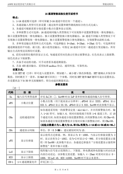
16通道智能巡检仪使用说明书特点:1、1-16通道数可选择(即可屏蔽2-16通道中的任何一个通道);2、各通道输入类型可任意设置(通过软件设置和硬件跳线相结合的方式完成);3、各通道可根据需要分别设置小数点位置和显示范围;4、多种报警方式可选择:16通道相同输入类型情况下可实现集中设置报警值统一继电器输出、独立设置报警值统一继电器输出、独立设置报警值独立继电器输出;16通道不同输入类型情况下可实现独立设置报警值统一继电器输出、独立设置报警值独立继电器输出;分别报警由副机完成;5、多种变送输出类型和方式可选择:可选择输出0-10mA、0-20mA、4-20mA信号;可选择所有通道测量值的平均值、最大值、最小值变送输出;可指定16通道中任何一通道进行变送输出;所有输出方式的变送范围均可设置;6、采用双排四位数码管显示方式,每通道采用双色指示灯指示报警状态,红色亮表示上限报警,绿色亮表示下限报警;7、具备手动巡检功能,可手动查看各通道测量值;8、具备485通讯输出,采用标准modbus协议,通用性强,可靠性高;设置方式:长按SET键(2秒)即可进入设置菜单,增加键∧、减小键∨修改参数值,SET键确认并保存参数值,同时跳至下一菜单,按MAN键可回到上一个参数,同时按SET键和MAN键即可退出设置状态;在设置状态下如50秒无按键操作,即自动退回测量状态;参数设置表Sn代码表:[表二报警指示:在巡检仪面板上有16只双色指示灯,用于各通道报警状态显示,即任意通道有上限报警信号时,其对应通道的指示灯红灯亮,统一报警时上限报警继电器吸合,分别报警时对应通道的上限报警继电器吸合;有下限报警信号时,对应通道的指示灯绿灯亮,统一报警时下限报警继电器吸合,分别报警时对应通道的下限报警继电器吸合,若没有报警信号则指示灯不指示。
统一报警时,16通道中任何一通道进入报警状态,即相应的报警继电器吸合,例如第2通道有上限报警信号时,仪表上限报警继电器即吸合,如果有多个通道同时有报警信号存在,则只有当所有通道的报警信号解除后相应的继电器才释放。
XSL16温度巡检仪英文版
SUZHOU SURPON INSTRUMENT CO.,LTDADD:F6hengfeng building,NO.26-6North Tongjing Road. Suzhou,Jiangsu province china Fax :0086-512-68381803SUZHOU SURPON INSTRUMENT CO.,LTD ADD:F6hengfeng building,NO.26-6North Tongjing Road. Suzhou,Jiangsu province china Fax :0086-512-68381803 11、GeneralSPB-XSL16 Series applies to measure, alarm and retransmit 2-16 channel signals of thermocouple and RTD. Ø Basic intrinsic error is less than 0.2%, indication range is -1999~9999. Ø The signal type, range, alarm value of each channel can be set separately.ØDigital filtering time coefficient of each channel, which can improve anti-interference ability, can be set separately.ØZero and full scale rectification, which can effectively reduce sensor errors to improve measuring accuracy, can be set separately.Ø Channels unused can be shut at will.SUZHOU SURPON INSTRUMENT CO.,LTD ADD:F6hengfeng building,NO.26-6North Tongjing Road. Suzhou,Jiangsu province china Fax :0086-512-68381803 2SUZHOU SURPON INSTRUMENT CO.,LTD ADD:F6hengfeng building,NO.26-6North Tongjing Road. Suzhou,Jiangsu province china 32、Technical SpecificationsInput RTD :Pt100,Cu100,Cu50,BA1,BA2,G53. Display solution is 0.1℃ for full range and disconnection identification is available.Thermocouple :K ,S ,R ,B ,N ,E ,J ,TDisplay solution can be set to 1 or 0.1℃℃ for full range (negative temperature included) anddisconnecting identification is availableAccuracy 16-bit A/D converterMeasuring Accuracy :±0.2%F·SDisplay Resolution :1/10000Rate200ms per channel (related to parameter )Display 2-digit LED channel number display 4-digit LED measured value displayAlarm state indicator of all channels Alarm 3 mode of alarm 2 public relaysRelay contact capacity: 250V AC ,2A (resistance load ) Power160V AC~260V AC ,50HzCircumstance Temperature :0~50℃℃Humidity :≤90%R·HSUZHOU SURPON INSTRUMENT CO.,LTD ADD:F6hengfeng building,NO.26-6North Tongjing Road. Suzhou,Jiangsu province china43、Installation and WiringFor the sake of safety, turn off the power supply before wiring.The terminalis a common terminal of power filter, with high voltage, which can only be connected tothe earth and connecting with other terminals is FORBIDDEN . Installation 【Dimensions 】【Cut-out Dimensions 】【wiring 】InputRTD:If the input signal is 2-wire, B and C should be shortcutting. Thermocouple:SUZHOU SURPON INSTRUMENT CO.,LTD ADD:F6hengfeng building,NO.26-6North Tongjing Road. Suzhou,Jiangsu province china 5Anode should be connected to A of the corresponding channel, while the cathode should be connected to the B of the corresponding channel.Input signal shielding layer can be connected to C .4、Faceplate & Keys4.1 FaceplateDisplay① Channel window : If the 2nd digit is flashing, the MVW is at fixed mode. ②Measured value window (MVW).③Alarm indicators: The first and the second alarm state of the current channel④Alarm indicators of each channel. The lights have three states : On—the current channel is in alarm. Off – the current channel isn’t in alarm. Glint-- the current channel is just in alarm.⑤Set Key⑥Mode key⑦Increase key⑧Decrease key,silenceKey is used to enter modifying state, move decimal point and display value of parameters coordinatelywith the other keys.SUZHOU SURPON INSTRUMENT CO.,LTD ADD:F6hengfeng building,NO.26-6North Tongjing Road. Suzhou,Jiangsu province china 64.2 Operation of function Circuit mode and fixed modeWhen the instrument is power on, it is in state of circuit measuring and display, which means to display thevalue and the number of each channel in turn, hereafter called “circuit mode ”, and it can be shifted to “fixed mod e”, which means to display only the number and the value of a chosen channel .To presskey in circuit mode can enter fixed mode, and the second digit of channel display is flickering, topress the key again can return to the circuit mode. In fixed mode, the channel can be chosen by changing the number of channels through pressingorkey.The instrument measures the value of each channel in a constant span of time and dose not affects normalmeasurement of the other channel even in fixed mode.5、Parameter Setting5.1 Alarm Value setting-- Set value of the first alarm-- Set value of the second alarmThe two parameters above are not controlled by security code.If no key is pressed for more than 50 seconds after entering setting state, the instrument will automatically exit setting state. 【Setting Steps 】① Presskey to enter fixed mode. The ones of the number in channel window is flickering. ②Pressorkey to select the channel needed to set.③Hold downkey for more than 2 seconds till entering setting state. The channel window displaysandMVW displays the channel number. Press ④key to choose AH or AL of the selected channel.⑤ Presskey to call out the initial value of the parameter. AH or AL is displayed on the channel windowand its value is displayed on MVW. The flashing digit is the one to be modified. ⑥Presskey again to shift the digit and usekey to increase orkey to decrease value to the onewanted.key has carry function,key has borrow function.⑦Presskey to confirm the modificationSUZHOU SURPON INSTRUMENT CO.,LTD ADD:F6hengfeng building,NO.26-6North Tongjing Road. Suzhou,Jiangsu province china 7Repeat steps ④ ~ ⑦ to set the second alarm set value of the selected channel.⑧ After step ⑦, press key to shift to the next channel and repeat steps ④ ~ ⑦ to set the parameters ofthe channel.⑨ After step ⑦, hold down key till the instrument exits setting state and returns to measuring state.【Duplication of Parameters 】Using the function of parameter duplication can reduce the works in parameter setting.If a parameter value of the next channel is the same with the one of current channel, press key at the step④ to copy that value.Example :If allneed to be set to 80.0 from channel 1 to channel 16, setof the 1st channel as abovementioned steps at first. Whileis displaying, presskey,is displayed and press keyagain,is appeared ……, in thissequence, tillis displayed on measuringwindow, the setting is done.5.2 Settings of Configuring ParameterPublic Configuring parameters are controlled by security code.In process of setting parameters, if no key is operated for more than 1 minute, the instrument would automatically exit setting state. 【Steps 】—Presskey to enter the fixed mode. The ones of channel number will be flashing.—Hold downkey for more than 2 seconds till the channel number is changed toto enter settingstate.— Hold downthe key for more than 2 seconds again tillis displayed whereas the instrument is insecurity code setting. —Pressto enter state of modification. Set the value to 1111 by pressing,orkeys.—Presskey to conform the setting and the security code is set. The public configuring parameters canbe set then. —Press key each time, the configuring parameters is displayed orderly.Presskey to enter modification state and the final digit is flashing. Useandkeys to modify the value to needed one.Presskey to save the value after modification and the next parameterappears automatically.SUZHOU SURPON INSTRUMENT CO.,LTD ADD:F6hengfeng building,NO.26-6North Tongjing Road. Suzhou,Jiangsu province china 8If modification of current parameter is no necessary, presskey to move to nextparameter.-- Time span of displaying.The setting range is 0.5~10.0 (seconds).It is the time span of display for each channel in circuit measuring state.--Channel number--Mode of cold junction compensationCoefficiency of cold junction compensation Alarm type of the 1st alarmThe default setting is— Upper limit alarm—Lower limit alarmAlarm type of the 2nd alarmThe default setting is— Upper limit alarm—Lower limit alarmAlarm hysteresis of the 1stAlarm. The default setting is 0. (See details in 6.4) Alarm hysteresis of the 2ndAlarm. The default setting is 0. (See details in 6.4) Silence delayThe default setting is 10【Exit 】As only parameter sign is indicating, hold down key till to exit setting state..3 Configuring Parameter Setting of All ChannelsConfiguring parameters of all channels include::Zero rectification. For more detail see Chapter 6.2. :Full scale rectification. For more detail see Chapter 6.2. :Selection of Input signal. For more detail see Chapter 6.1.:Decimal point position of measured value. For more detail see Chapter 6.1. :Time co efficiency of digital filtering. For more detail see Chapter 6.1.SUZHOU SURPON INSTRUMENT CO.,LTD ADD:F6hengfeng building,NO.26-6North Tongjing Road. Suzhou,Jiangsu province china 9Configuring parameters of all channels are controlled by security code. These parameters are in the same group as the alarm set value and can be set according to the Chapter 5.2 after the security code is set.6、Illustration on Functions & Corresponding Parameters6.1 Input Signal & displayParameters F ollowing Parameters should be correctly set, otherwise the instrument cannot work properly.Parameters of a channel are independent to the other channels’ and should be set one by one according toeach channel. If information about input signal on ordering is integrity, the related parameters would be set accordingly before the instrument is delivered.(For setting referred to Chapter 5.2.)Selection of Input signalsSelection should be in accordance with the actual input. The value of a parameter is expressed in a formof symbol. The following list shows the corresponding relations:No. SignsInput Signal0 Not in use.1 RTD Pt100,full scale2 RTD Cu100,full scale3 RTD Cu50,full scale4 RTD BA1,full scale5 RTD BA2,full scale6 RTD G53,full scale7 Thermocouple K ,full scale (negative temperature included ) 8 Thermocouple S ,full scale (negative temperature included ) 9 Thermocouple R ,full scale (negative temperature included ) 10 Thermocouple B ,full scale11 Thermocouple N ,full scale (negative temperature included ) 12 Thermocouple E ,full scale (negative temperature included ) 13 Thermocouple J ,full scale (negative temperature included ) 14Thermocouple T ,full scale (negative temperature included )Selection for decimal point position of measured valueSUZHOU SURPON INSTRUMENT CO.,LTD ADD:F6hengfeng building,NO.26-6North Tongjing Road. Suzhou,Jiangsu province china10 RTD input channel: The only selection is 000.0 Display resolution is 0.1℃.Thermocouple input channel: Both 0000 and 000.0 can be selected, display resolution is 1℃ for0000 and is 0.1℃ for 000.0 , which the maximum range is 999.9℃.For thermocouple B, S, T, R, the displaying value may be fluctuate because the input signal is too small.Therefore the 0.1℃ mode is not recommended in these circumstances.Time coefficiency of digital filtering (1 to 100)Digital filtering can reduce fluctuation of indicated value caused by input fluctuation and interference.The larger the setting value of is the greater the effect will be and the slower the reaction of theinstrument to the change of the input signal is.6.2 Zero and Full Scale CorrectionIllustration There would be errors in measurement of a specific engineering value due to variety of factors fromsensors, Retransmitted output and instrument itself, with usage of the rectification could reduceeffectively the errors and improve the accuracy of measurement and control for the whole system.Formula:Rectified Value =×(Measured Value before rectified+) Parameter—— Zero rectification—— Full Scale rectificationSteps①Before correction, make the channel be unmodified state by settingof the channelto be 0000 and to be 1.000.② Process the zero rectification.③Process the full scale rectification.Example: Input : Pt100 -- measuring range is 0~200.0℃The actual temperature of the 1st channel should be 0.0℃, because of the sensor error, the indication is0.8℃. set of the 1st channel to be -0.8, then the indication is modified to 0.0℃. 6.3 Cold Junction CompensationIllustration The voltage(measured in mV) created by thermocouple reflects the temperature difference between workingterminal (the pot measured )and reference terminal(the cold terminal). Because reference terminal has its owntemperature, the actual temperature should be the temperature difference mentioned before adding thisreference temperature, which is called cold junction compensation.There are 2 compensation types according to actual wiring.SUZHOU SURPON INSTRUMENT CO.,LTD ADD:F6hengfeng building,NO.26-6North Tongjing Road. Suzhou,Jiangsu province china11 Principle Compensated V alue (mV) =V alue (mV) created by thermocouple + V alue (mV) corresponded to the ColdJunctionFor example: Thermocouple S creates 9.587mV signal, which means the temperature difference betweenworking terminal and cold junction is 1000℃. At this time the cold junction temperature is 30℃, thecorresponding mV value is 0.173mV .Then the compensated value = 9.587 + 0.173 = 9.760mV . The corresponding temperature is 1015℃,which is the actual temperature of the working terminal.Type 1 The compensation leads of thermocouple are directly connected to the instrument terminals.T he cold junction temperature is just the instrument terminal temperature. The instrument measurestemperature through thermoscope at the terminal, and the compensation is automatically done. Ifshortcut the input terminals, the indicated value should be the actual temperature of the terminals.The instrument is set according to this mode before delivering and is checked.must be set 0061.is the cold junction coefficient. If there are errors after cold junction compensation, modification can be done by using thisparameter. By Increasing or decreasing the value of this parameter, the compensated temperature gainsor reduces accordingly.Type 2 The compensation leads are connected to a constant temperature device, the cold junction temperature isthe actual temperature of this device.must be set to be the actual temperature of the device.must be set to be 0.6.4 AlarmIllustration Alarm is the reaction of the indicator and output relay of the instrument when measured value exceedsthe set range. Alarm includes 4 factors which are set value, alarm type, alarm hysteresis and output modeof relays.Parameter——Set value of the 1st alarm ,independently setting for each channel.——Set value of the2nd alarm ,independently setting for each channel.——Alarm type of first alarm for all channels.If the setting ismeans upper limit alarm.If the setting ismeans lower limit alarm. ——Alarm type of second alarm for all channels.SUZHOU SURPON INSTRUMENT CO.,LTD ADD:F6hengfeng building,NO.26-6North Tongjing Road. Suzhou,Jiangsu province china12If the setting is means upper limit alarm.If the setting ismeans lower limit alarm. Bysettingand , the instrument can conduct upper or lower limit alarm, upper-upperlimit alarm and lower-lower limit alarm——Alarm hysteresis of 1stalarm for all channels——Alarm hysteresis of 2ndalarm for all channels——Silence delay . range : 0~51. The state of Alarm indicators and alarm type is decide by theparameter.Output ModeFor an instrument of 2 relays of alarm, there are 3 acting modes by setting(Defaulted setting is 1) 1is set to 1~50 .this mode will clue on time.RL1 : any of channel is on alarm, RL1 is on . Auto delay resume or by thekey resume, the delay time is set by. range 1~50 second.2is set to 51 . The same as the first mode .but RL1 can’t be auto delay resume , only by the key resume 3is set to 0 .RL1 only the first alarm of each channel is in alarm state, the relay will be on.RL2 only the second alarm of each channel is in alarm state, the relay will be on.Alarm indicatorsEvery channel have own Alarm indicators, the lights have three states : on, off and glint.Glint – The current channel is just in alarm. when RL1 resume, the light will be on from glint,On – The current channel is in alarm. Off – The current channel isn’t in alarm.。
PH5说明书
智能巡检管理系统WM-5000PH5使用说明书欢迎您使用信达盛智能巡检管理系统在您使用巡检器之前,请先仔细阅读全部安全注意事项和说明书,以确保安全和正确使用。
说明书中的说明基于设备的默认设置。
说明书中所用的图像和屏幕截图可能与实际产品不同,以实物为准。
说明书中的内容可能与产品不同,如有变更,恕不另行通知。
版权版权所有陕西信达盛铁路设备有限公司2015。
保留一切权利。
非经陕西信达盛铁路设备有限公司书面同意,任何单位和个人不得擅自摘抄、复制本说明书的部分或全部内容,并不得以任何形式传播。
注意事项请勿使用损坏的电源线、插头或者松动的电源插座。
请勿用湿手接触电源线,或通过拉拽电线的模式拔下充电器。
在可能发生危险的环境下,始终按照规定进行操作。
避免充电器短路。
禁止拆卸任何部件。
禁止将巡检器用火烘烤。
禁止将巡检器长时间置入水中浸泡或恶意摔砸。
目录1.系统描述 (3)2.包装清单 (3)3.系统要求 (3)3.1电脑配置 (3)3.2操作系统要求 (4)4.系统组成 (4)5.主要功能介绍 (5)5.1 GPS定位 (5)5.2 GPRS无线传输 (5)6智能巡检管理系统 (6)6.1启动图标 (6)6.2登陆系统 (6)6.3巡检界面(采用百度地图) (7)6.4菜单功能 (7)6.4.1重新登陆 (8)6.4.2查看线路 (8)6.4.3 GPS采点 (9)6.4.4加载地图 (9)6.4.5 参数设置 (10)6.4.6 上传数据 (11)6.5 采集地点 (12)6.6拍摄照片功能 (12)6.6.1定点拍照 (12)6.6.2随机拍照 (12)6.7巡检内容功能 (13)7.售后服务 (13)8.服务响应时间≤24小时 (14)9.保修条款 (14)10.参数说明 (15)1.系统描述“J.博士”巡检管理系统,基于Android4.2操作平台,配置GSM/WCDMA 数据通讯方案。
外观坚固,工业级设计,配置3.5寸320*480分辨率LCD液晶显示屏,功能强大,采用世界领先的GPS全球卫星定位技术和无线射频识别技术。
智能巡检系统使用说明书
此说明乃是按照智能巡检系统正常操作流程编写,如还有不明白或是带疑问的地方请与卖方联系,感谢您使用此机器和软件!!巡检系统使用大致步骤:巡更机装好电池→连接好电脑→校时→设置巡检点→设置人员→设置线路→设置计划→下载数据→计划分析→计划考核巡检系统使用各步骤详情:装软件打开智能巡检系统的软件,然后按照提示装好软件,然后点击【确定】进入巡检系统(初始密码为空,不用输入)校时图解:1.巡检机先装好电池,然后用数据线与电脑连接好,在【系统设置】中点开【参数设置】。
2.在【参数设置】里面点击【校时】,提示校时成功即可完成对巡检机的校时。
(PS:当巡检机断电过久时就要对巡检机进行校时才能正常读点)设置巡检点图解:1.先依次标记并排好要设置的巡检点,然后依次按顺序的读好排列好的巡检点;把巡检机与电脑连接好,打开智能巡检系统,在【资源设置】中点开【巡检点设置】。
2.点击【采集数据】采集巡检机里面的巡检的数据。
3.显示巡检机里面采集到的巡检点数据并注册到【巡检点设置】中。
4.在巡检点名称中编辑巡检点所对应的地点名称,双击“名称”可直接修改您所需要对应的地点名称。
设置人员图解:1.先依次标记并排好要设置的人员钮,然后依次按顺序的读好排列好的人员钮;把巡检机与电脑连接好,打开智能巡检系统,在【资源设置】中点开【人员设置】。
2.点击【采集数据】采集巡检机里面的巡检的数据。
3.显示巡检机里面采集到的人员钮数据并注册到【人员设置】中。
4.在人员名称中编辑人员钮所对应的人员名称。
设置线路图解:1.在【资源设置】中点开【线路设置】。
2.点击【增加】以增加线路。
3.输入线路名称。
4.点击【保存】以保存线路。
5.选择要设置的线路然后勾选线路中要巡逻的巡检点。
6.勾选好巡检点后点击【左移】把勾选的巡检点添加到线路下。
设置计划图解:1.在【资源设置】中点开【计划设置】。
2.勾选要巡检的是星期几。
3.选择线路。
4.选择每天开始巡检时间和结束时间。
- 1、下载文档前请自行甄别文档内容的完整性,平台不提供额外的编辑、内容补充、找答案等附加服务。
- 2、"仅部分预览"的文档,不可在线预览部分如存在完整性等问题,可反馈申请退款(可完整预览的文档不适用该条件!)。
- 3、如文档侵犯您的权益,请联系客服反馈,我们会尽快为您处理(人工客服工作时间:9:00-18:30)。
1. SummaryYK-19 series intelligent Channels Measurement instrument is intelligent, high accuracy controller for temperature, pressure or level measurement. When use it to equipped with temperature, pressure or level sensor, we can consist temperature, pressure or level measurement control system for various type and range. provideRS232 or RS485 to communication with computer or PLC。
The instrument has a real-time clock for user get date and time。
2.T echnical specificationsInput signal: Resistance temperature Detector Pt100, Cu50, Cu100,3 wires conncetMeasurement accuracy : 0.2%FS±1 digitAlarm Output: buzzercommunication: isolation RS485, baud 1200~9600bps。
transmit: isolation 4-20mA for the first channel,<250ΩDisplay : double 4 digit LED display.Power suply: 220V AC.Power c onsumption: 2WTemperature: 0~50℃Ambient humidity: <85%RHFront panel dimension : 160mm×80mmInstallation dimension : 152mm×76mm3. OperationKey-press DescriptionPress the KEY to mute the Buzzer.at setting parameters state, press the key return to work state. At workstate, press the key to switch cycle display and static display. While at cycle display state,the bottom LED are display –xx-, at static display。
Press the SET key to enter setting status.,After chang the current parameterat setting parameters state, press ▲key making parameter increase one.and hold the ▲key, value will increase or decrease quickly and release for stop. At static display state, press ▲key will change to next channels value display.at setting parameters state, press▼key making parameter decrease one. and hold the ▼key, value wil decrease quickly and release for stop. At static display state, press the key will change to next channels value display.After power on the display window displays HELO to indicate self-checking is right, displays -HH- indicates input over range or sensor disconnection or short-circuit. Instrument adopts man to machine talk model for input parameter, and use various prompting to indicate what kind of data should input. At the work state, the up LED display measured value,the bottom LED display the number of the corresponding channel.The last two are the date(-Ht-) and time(-Lt-).(1)press the En key, the up display window displays –Cd-,bottom LED will display 800, Only 800 is changed to 808, and then press En key again will make the instrument to access the setup parameter setting status, other value is denied for preventing field operators from set parameters incorrectly by mistake.(2) -LP-: the instrument measuring the number of channels,rang:1~16, Factory default 10.(3)1-Sn:the first channel intput sensor type,Reference the table below,Factory default P100.Rang 0-3,Factory default 1.(5)1-PL: the 1st channel lower range value, only for the first,it is lower range value for the transmitter output too.(6)1-PH: the 1st channel higher range value, only for the first,it is higher range value for the transmitter output too. For example,1-PL=0.0,1-PH=300.0, first channel measured value is150.0,then the output 4-20mA value is 12.0mA.(7)2-Sn:the 2nc channel intput sensor type.……(8)1-HA: the 1st channel ultra-high alarm value.(9)1-LA: the 1st channel ultra-low alarm value.……(10)1-Eo: the 1st channel measured value deviation rectify.ex: actual the 1st value is 30.0, currently display value is 29.2,then the parameter 1-Eo=0.8.Factory default 0.0 (11)2-Eo: the 2nd channel measured value deviation rectify.……(12)Addr:the communication address for computer, rang 01~99。
Factory default 1(13)baud:the communication baud for computer, 1200、2400、4800、9600 four items for choice。
Factory default 9600.(14)-Ht-: Current clock date, rang 1.01~12.31.(15)-Lt-: Current clock time, rang 0:00~23.59.(16)tS—the cycle display interval, unit second, rang 1~9999,Factory default 5After parameter sets are finished, LED will display End and then go to working status.4. Communication specificationsThe instrument has RS485 interface, direct communication with the computer.RS485 standard communication distance 1.5km, Can be connected to multiple devices/ instrument.Data character format is 1 initial bit , 8 data bits, 1 stop bit, no parity bit.The instrument using modbus-rtu standard communication protocols,using 3x or 4x. Register addres from 1 to 18.4x001 1 ch value4x002 2 ch value……4x016 16 ch value4x017 clock date4x018 clock timeEX:the parameter Addr=1,the 1 channel value=100.0host send query message: 01 03 00 00 00 01 84 0A.Instrument return data: 01 03 02 03 E8 B8 FA.(0x03e8=1000)5. T erminal wiringrecommended 6 months energized the 24-hour clock battery charging.。
