D6T MEMS非接触温度传感器-欧姆龙
OMEGA CNi16温度传感器控制器说明书

The OMEGA ® CNi16 is the popular 1⁄16 DIN size (48 mm 2) controller. It is available with a single (model CNi16) or dual display (model CNi16D) that displays a setpoint along with the process value. The CNi16 display can be programmed to change color between GREEN, AMBER, and RED at any setpoint or alarm point. The CNi16 is the first 1⁄16 DIN controller with the option of both RS232 and RS485 in 1 instrument with straightforward OMEGA ® ASCII protocol. And of course the CNi16 is the first 1⁄16 DIN controller that can connect directly to an Ethernet network and features an embedded Web server. OMEGA ® provides free configuration and data acquisition software downloaded off of the Web.The CNi16 enclosure has a NEMA 4 (IP65) rated front bezel. The electronics are removable from the front panel. U U niversal InputsU H igh Accuracy: 0.5°C (±0.9°F), 0.03% ReadingU T otally Programmable Color Displays (Visual Alarms)U U ser-Friendly, Simple to ConfigureU F ree Software DownloadU Full Autotune PID ControlU E mbedded Ethernet Connectivity OptionalU R S232 and RS485 Serial Communications OptionalU B uilt-In ExcitationU 2 Control or Alarm Outputs Optional: DC Pulse, Solid State Relays, Mechanical Relays, Analog Voltage and CurrentU O utput 3: Isolated Analog Voltage and Current OptionalU NEMA 4 (IP65) Front BezelU T emperature Stability: ±0.04°C/°C RTD and ±0.05°C/°C Thermocouple @ 25°C (77°F)U F ront Removable and Plug ConnectorsU A C or DC Powered UnitsU R atiometric Mode for Strain GagesU P rogrammable Digital Filter1 ⁄16 DIN controller with embedded Web server, dual control outputs, dual display.Anywhere, On the Internet!1⁄16 DIN Temperature, Process andStrain PID ControllersCNi16D33 shown larger than actual size.CNi1633 shown larger than actual size.1controllers only.*2 “-DC”, “-C24”, and “-C4EIT” not available with excitation.*3A nalog output (option 5) is not available with “-AL” units orCNi16A models.*4 20 to 36 Vdc for CNi16D, CNi16D-C4EIT, CNi16D-EIT and CNi16A. *5“-SM” option not available on CNiS16 or CNi16A models.*6 Ethernet options are not available for CNi16A models.*7 For CNi16A0x-AL: one alarm and one analog retransmission.Ordering Examples: CNi1633, temperature/process controller, output 1 relay, output 2 relay single display, 90 to 240 Vac power. CNiS1643, strain/process controller, output 1 DC pulse, output 2 relay, single display, 90 to 240 Vac power.Universal Temperature and Process Input (DPi/CNi Models)Accuracy: ±0.5°C temp; 0.03% rdg Resolution: 1°/0.1°; 10 µV process Temperature Stability: RTD: 0.04°C/°C TC @ 25°C (77°F): 0.05°C/°C Cold Junction Compensation Process: 50 ppm/°C NMRR: 60 dB CMRR: 120 dB A/D Conversion: Dual slope Reading Rate: 3 samples/s Digital Filter: Programmable Display: 4-digit 9-segment LED 10.2 mm (0.40"); i32, i16, i16D, i8DV 21 mm (0.83"); i8 10.2 mm (0.40") and 21 mm (0.83"); i8DH RED , GREEN, and AMBER programmable colors for process variable, setpoint and temperature units Input Types: Thermocouple, RTD, analog voltage, analog current Thermocouple Lead Resistance: 100 Ω max Thermocouple Types (ITS 90): J, K, T, E, R, S, B, C, N, L (J DIN)RTD Input (ITS 68): 100/500/1000 Ω Pt sensor, 2-, 3- or 4-wire; 0.00385 or 0.00392 curve Voltage Input: 0 to 100 mV, 0 to 1V, 0 to 10 Vdc Input Impedance: 10 M Ω for 100 mV 1 M Ω for 1 or 10 Vdc Current Input: 0 to 20 mA (5 Ω load)Configuration: Single-ended Polarity: Unipolar Step Response: 0.7 sec for 99.9%Decimal Selection: Temperature: None, 0.1 Process: None, 0.1, 0.01 or 0.001Setpoint Adjustment: -1999 to 9999 counts Span Adjustment: 0.001 to 9999 counts Offset Adjustment: -1999 to 9999Excitation (Not Included with Communication): 24 Vdc @ 25 mA (not available for low-power option)Universal Strain and Process Input (DPiS/CNiS Models)Accuracy: 0.03% reading Resolution: 10/1µV Temperature Stability: 50 ppm/°C NMRR: 60 dB CMRR: 120 dB A/D Conversion: Dual slope Reading Rate: 3 samples/s Digital Filter: Programmable Input Types: Analog voltage and current Voltage Input: 0 to 100 mVdc, -100 mVdc to 1 Vdc, 0 to 10 Vdc Input Impedance: 10 M Ω for 100 mV;1 M Ω for 1V or 10 Vdc Current Input: 0 to 20 mA (5 Ω load)Linearization Points: Up to 10 Configuration: Single-ended Polarity: Unipolar Step Response: 0.7 sec for 99.9%Decimal Selection: None, 0.1, 0.01 or 0.001Setpoint Adjustment: -1999 to 9999 counts Span Adjustment: 0.001 to 9999 counts Offset Adjustment: -1999 to 9999Excitation (Optional In Place Of Communication): 5 Vdc @ 40 mA;10 Vdc @ 60 mA Control Action: Reverse (heat) or direct (cool)Modes: Time and amplitude proportional control; selectable manual or auto PID, proportional, proportional with integral, proportional with derivative and anti-reset Windup, and on/off Rate: 0 to 399.9 s Reset: 0 to 3999 s Cycle Time: 1 to 199 s; set to 0 for on/off Gain: 0.5 to 100% of span; setpoints 1 or 2Damping: 0000 to 0008Soak: 00.00 to 99.59 (HH:MM), or OFF Ramp to Setpoint: 00.00 to 99.59 (HH:MM), or OFF Auto Tune: Operator initiated from front panel Control Output 1 and 2Relay: 250 Vac or 30 Vdc @ 3 A (resistive load); configurable for on/off, PID and ramp and soak Output 1: SPDT, can be configured as alarm 1 output Output 2: SPDT, can be configured as alarm 2 output SSR: ******************.5A (resistive load); continuous DC Pulse: Non-isolated; 10 Vdc @ 20 mA Analog Output (Output 1 Only):Non-isolated, proportional 0 to 10 Vdc or 0 to 20 mA; 500 Ω max Output 3 Retransmission: Isolated Analog Voltage and Current Current: 10 V max @ 20 mA output Voltage: 20 mA max for 0 to 10 V output Network and Communications Ethernet: Standards compliance IEEE 802.3 10 Base-T Supported Protocols: TCP/IP, ARP, HTTPGET RS232/RS422/RS485: Selectable frommenu; both ASCII and MODBUS protocol selectable from menu; programmable 300 to 19.2 Kb; complete programmable setup capability; program to transmit current display, alarm status, min/max, actual measured input value and status Common Specifications (Alli/8, i/16, i/32 DIN)RS485: Addressable from 0 to 199Connection: Screw terminals Alarm 1 and 2 (Programmable)Type: Same as output 1 and 2Operation: High/low, above/below,band, latch/unlatch, normally open/normally closed and process/deviation; front panel configurations Analog Output (Programmable):Non-isolated, retransmission 0 to 10 Vdcor 0 to 20 mA, 500 Ω max (output 1 only); accuracy is ± 1% of FS when following conditions are satisfied: input is not scaled below 1% of input FS, analog output is not scaled below 3% of output FS General Power: 90 to 240 Vac ±10%, 50 to 400 Hz *, 110 to 300 Vdc, equivalent voltage Low Voltage Power Option: 24 Vac **, 12 to 36 Vdc for DPi/CNi/DPiS/CNiS; 20 to 36 Vdc for dual display, ethernet and isolated analog output from qualified safety approved source Isolation Power to Input/Output: 2300 Vac per 1 minute test For Low Voltage Power Option: 1500 Vac per 1 minute test Power to Relay/SSR Output: 2300 Vac per 1 minute test Relay/SSR to Relay/SSR Output:2300 Vac per 1 minute test RS232/485 to Input/Output:500 Vac per 1 minute test Environmental Conditions: All Models: 0 to 55°C (32 to 131°F) 90% RH non-condensing Dual Display Models: 0 to 50°C (32 to 122°F), 90% RH non-condensing (for UL only) Protection: D Pi/CNi/DPiS/CNiS32,16,16D, 8C: NEMA 4X/Type 4 (IP65) front bezel DPi/CNi/DPiS/CNiS8, 8DH, 8DV: NEMA 1/Type 1 front bezel Approvals: UL, C-UL, CE per 2014/35/EU, FM (temperature units only)Dimensions i /8 Series: 48 H x 96 W x 127 mm D (1.89 x 3.78 x 5") i/16 Series: 48 H x 48 W x 127 mm D (1.89 x 1.89 x 5") i/32 Series: 25.4 H x 48 W x 127 mm D(1.0 x 1.89 x 5")Panel Cutouti /8 Series: 45 H x 92 mm W (1.772 x 3.622"), 1⁄8 DIN i/16 Series: 45 mm (1.772") square,1⁄16 DINi/32 Series: 22.5 H x 45 mm W (0.886 x 1.772"), 1⁄32 DIN Weighti /8 Series: 295 g (0.65 lb) i/16 Series: 159 g (0.35 lb) i/32 Series: 127 g (0.28 lb)* No CE compliance above 60 Hz.** Units can be powered safely with 24 Vacpower, but no certification for CE/UL are claimed.。
OMRON光电传感器操作手册
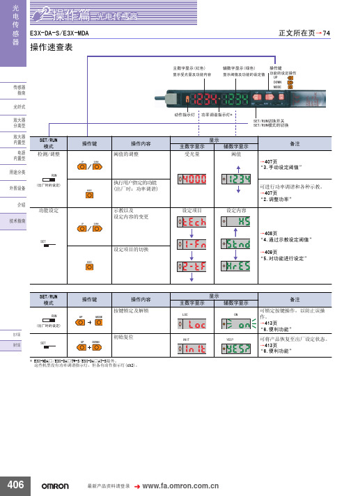
݊Ёӏϔ䬂 ᣝV
᳝Ꮉӊ⢊ᗕϟ
Ꮉ 7(&+ ----
݊Ёӏϔ䬂 ᣝV
Ā----ā䮾⚕
Ā----ā䮾⚕
83 581 '2:1
㟇581
᮴Ꮉӊ⢊ᗕϟ
5)&+ 䯜ؐ
݊Ёӏϔ䬂 ᣝV
7+58
䯜ؐ
ĀᏆ䆒ᅮདⱘ䯜ؐā䮾⚕
ĀᏆ䆒ᅮདⱘ䯜ؐā䮾⚕
ফܝ䞣
䯜ؐ
ফܝ䞣
䯜ؐ
䆒ᅮ㒧ᴳৢˈ䖨ಲࠄ ᪡ࠡⱘᰒ冫
406
᳔ᮄѻક䌘᭭䇋ⱏᔩ
᪡㆛⬉ܝӴᛳ఼
ܝ ⬉ Ӵ ᛳ ఼
⊼
ৠᯊᣝV
䆒ᅮࡼᓣ
ৃҹ䗮䖛ߛᤶᓔ݇䆒ᅮࡼᓣDŽ ࡼᓣ ᪡ /g21 'g21
/
ߎॖᯊⱘ䆒ᅮ
>䖨ಲ߱ྟܝ䞣ᯊ@
'2:1 02'(
ܹܝᯊ21 䙂ܝᯊ21
⊼ᣝ02'(䬂ৢ䇋ゟेᣝ'2:1䬂DŽ
显示 主数字显示
/2&
辅数字显示
21
备注 可锁定按键操作,以防止误操 作。 →413页 “6.便利功能” 可将产品恢复至出厂设定状态。 →413页 “6.便利功能”
UP
MODE
ᡔᴃ㆛ ᪡㆛
6(7
UP DOWN
初始复位
,1,7
<(6"
* E3X-MDA□/E3X-DA□TW-S/E3X-DA□AT-S除外。 这些机型没有功率调谐指示灯,但备有动作指示灯(ch2)。
䗮䖛ᬍ䆒ᅮݙᆍDŽ
ࡳ㛑ৡ鹵
ࡼᓣ Ẕ⌟ࡳ㛑
䆒ᅮݙᆍ ᰒ冫
ܹܝᯊ21˖ǃ䙂ܝᯊ21˖ ᳔ᖿ˖ǃ催䗳˖ǃᷛ˖ޚǃ催㊒ᑺ˖ǃ ᖂߚࡼ˖ ҙ催ࡳ㛑ൟ
常用电机测温用NTC温度传感器

3~6 28±5
520±10
NTC/SC.DJNTC-200T1K.02.029-2017
版次:VER2.10
共5页
第4页
2.3 Electrical characteristics 电性能
Item 项目
Symbol 符号
Test Condition 测试条件
a
Resistance at 25°C 25°C 电阻值
NTC/SC.DJNTC-200T1K.02.029-2017
版次:VER2.10
共5页
第3页
1、 产品名称、型号、代码、型号规则 名称:电机用 NTC 温度传感器 型号:DJNTC1-200TR1KJB4315FX 代码:200TR1KJB4315FX 型号规则:
DJNTC 110
200TR1 K
下限值
22343.3042 20718.1923 19221.8509 17843.2802 16572.4850 15400.3777 14318.6905 13319.8966 12397.1401 11544.1719 10755.2926 10025.3016 9349.4501 8723.3994 8143.1836 7605.1751 7106.0540 6642.7804 6212.5692 5812.8674 5441.3333 5095.8181 4774.3489 4475.1133 4196.4456
5.4
耐温度冲击
*∆R25/ R25≤±2%
Method of Examination 测试条件及方法
After storeage at 250°C for 1000hrs 250°C 环境中放置 1000 小时 After storeage at -40°C for 1000hrs -40°C 环境中放置 1000 小时
微机电系统(MEMS)技术介绍

微机电系统(MEMS)技术介绍微机电系统(MEMS),在欧洲也被称为微系统技术,或在日本被称为微机械,是一类器件,其特点是尺寸很小,制造方式特殊。
MEMS是指采用微机械加工技术批量制作的、集微型传感器、微型机构、微型执行器以及信号处理和控制电路、接口、通讯等于一体的微型器件或微型系统。
MEMS 器件的特征长度从1毫米到1微米--1微米可是要比人们头发的直径小很多。
MEMS往往会采用常见的机械零件和工具所对应微观模拟元件,例如它们可能包含通道、孔、悬臂、膜、腔以及其它结构。
然而,MEMS器件加工技术并非机械式。
相反,它们采用类似于集成电路批处理式的微制造技术。
今天很多产品都利用了MEMS技术,如微换热器、喷墨打印头、高清投影仪的微镜阵列、压力传感器以及红外探测器等。
MEMS技术可以用于制造压力传感器、惯性传感器、磁力传感器、温度传感器等微型传感器,这些传感器以及它们的部分信号处理电路都可以在只有几毫米或更小的芯片上实现。
与传统的传感器相比,MEMS传感器不仅体积更小、功耗更低,而且它们往往会比传统传感器更加准确、更加灵敏。
随着人们对海洋观测的需求不断增加和海洋观测技术的不断发展,MEMS技术也在逐渐进入海洋观测技术研究领域。
一、MEMS概念“他们告诉我一种小手指指甲大小的电动机。
他们告诉我,目前市场上有一种装置,通过它你可以在大头针头上写祷文。
但这也没什么;这是最原始的,只是我打算讨论方向上的暂停的一小步。
在其下是一个惊人的小世界。
公元2000年,当他们回顾当前阶段时,他们会想知道为何直到1960年,才有人开始认真地朝这个方向努力。
”——理查德·费曼,《底部仍然存在充足的空间》发表于1959年12月29日于加州理工大学(Caltech)举办的美国物理学会年会。
但我们可能会问:为什么要在这样一个微小尺上生成这些对象?MEMS器件可以完成许多宏观器件同样的任务,同时还有很多独特的优势。
这其中第一个以及最明显的一个优势就是小型化。
ELX1106 NRBE 非线性变化温度电阻芯(NTC)温度传感器说明说明书

NRBEEpoxy sealed radial lead NTC thermistorProduct features• Faster thermal response• Epoxy sealed radial NTC thermistor •Non-linear change in resistance vs temperatureApplications• Industrial process control • Commercial appliances•Battery, supercapacitor and energy storage systems• Uninterruptible power supplies • Consumer appliances • Medical devices•Heating, ventilation and air conditioning, refrigeration (HVACR)• Food service equipment•IoTEnvironmental compliance and general specificationsPb HALOGENHFFREEAgency information•cURus recognition file: E343021Packaging information•Bulk: 500 parts per poly bagT able 1. Part numberingNRB E xxy x xxxx Bx x zFamily nameNRBPackaging typeEpoxy coatedResistancex.x * 10y Ω; ex: 3.4 * 105 Ω = 345Resistance toleranceF = ±1%, J= ±5%, 2 = ±0.2%Beta toleranceF = ±1%, J = ±5%Beta typeB1=25/50, B2=25/85Beta value ex: 3465, 4215, etcCustom (optional)Different chip sizeor lead dimensions2Technical Data ELX1106Effective December 2021NRBE Epoxy sealed radial lead NTC thermistor/electronicsMechanical parameters- mm/inchesMillimetersInches Dimension MinimumMaximumMinimumMaximumA 1.7 2.70.06690.106B 4.0 6.00.1570.236C 1.0 3.00.0390.118D 0.280.380.0110.015L30361.1811.417Electrical specificationsPart numberRatedtemperatureResistance (kΩ)Beta value (K)Beta type cURusNRBE233?3935B1*+25 °C 2.2523935B25/50NRBE303?3950B1*+25 °C 33950B25/50NRBE503?3300B2*+25 °C 53300B25/85NRBE503?3470B1*+25 °C 53470B25/50NRBE503?3950B1*+25 °C 53950B25/50NRBE104?3380B1*+25 °C 103380B25/50x NRBE104?3435B2*+25 °C 103435B25/85x NRBE104?3500B2*+25 °C 103500B25/85x NRBE104?3950B1*+25 °C 103950B25/50x NRBE104?4100B1*+25 °C 104100B25/50x NRBE154?4150B1*+25 °C 154150B25/50xNRBE234?4200B1*+25 °C 234200B25/50NRBE504?3950B1*+25 °C 503950B25/50NRBE105?3950B1*+25 °C 1003950B25/50NRBE105?4150B1*+25 °C 1004150B25/50NRBE105?4200B1*+25 °C 1004200B25/50NRBE105?4450B1*+25 °C 1004450B25/50NRBE353?3435B2*+50 °C 3.45133435B25/85NRBE324?4550B2*+50 °C 31.7654550B25/85NRBE203?4250B2*+86 °C2.0284250B25/85= Enter resistance tolerance codes (F = ±1%,J = ±5%, 2 = ±0.2%)*= Enter Beta tolerance codes (F = ±1%, J = ±5%)Dissipation coefficient: ≈0.8 mW/ °C Thermal time constant: ≤10 sWithstand voltage: 300 Vac/1 mA/60 s Insulation resistance: 50 Vdc/50 MΩ/60 s Operation temperature: -40 °C to +125 °C3Technical Data ELX1106Effective December 2021NRBEEpoxy sealed radial lead NTC thermistor /electronicsPart number NRBE233?3935B1*NRBE303?3950B1*NRBE503?3300B2*NRBE503?3470B1*NRBE503?3950B1*Resistance 2.252K(25 °C)3K(25 °C)5K(25 °C)5K(25 °C)5K(25 °C)Beta Value B25/50=3935B25/50=3950B25/85=3300B25/50=3470B25/50=3950Temperature (°C)Resistance (kΩ)Resistance (kΩ)Resistance (kΩ)Resistance (kΩ)Resistance (kΩ)-4068.4591.1893.37110.53154.07-3964.485.7988.32104.22144.64-3860.6280.7583.5898.32135.85-3757.0776.0379.1392.78127.65-3653.7571.6174.9587.6119.98-3550.6467.4771.0182.74112.83-3447.7363.5867.3178.19106.14-334559.9463.8373.9199.88-3242.4356.5360.5569.994.03-3140.0353.3257.4666.1388.56-3037.7750.3154.5562.5983.44-2935.647.4351.859.2778.68-2833.5844.7349.2156.1574.22-2731.6742.246.7653.2170.03-2629.8939.8244.4550.4466.11-2528.2237.5942.2747.8462.42-2426.6435.4940.2245.3858.96-2325.1733.5338.2743.0755.71-2223.7831.6836.4340.8952.65-2122.4829.9534.738.8449.78-2021.2528.3233.0536.947.08-1920.126.7731.4935.0744.56-1819.0125.3330.0133.3542.18-1717.9923.9628.6131.7239.94-1617.0322.6827.2930.1837.83-1516.1221.4826.0328.7235.85-1415.2720.3424.8527.3433.97-1314.4619.2723.7226.0432.2-1213.7118.2622.6524.8130.54-1112.9917.3121.6423.6428.96-1012.3216.4120.6822.5427.47-911.6915.5719.7621.4926.05-811.0914.7718.920.5124.72-710.5214.0218.0819.5723.45-69.9913.317.318.6822.26-59.4812.6316.5517.8421.13-49.011215.8517.0420.07-38.5611.415.1716.2819.06-28.1310.8314.5415.5518.12-17.7310.313.9314.8717.2207.359.7913.3514.2216.371 6.989.312.7913.5915.552 6.648.8512.271314.783 6.318.4111.7612.4314.064 6.01811.2911.913.375 5.727.6210.8311.3912.726 5.447.2510.3910.912.117 5.18 6.99.9810.4411.538 4.9351 6.579.581010.989 4.7019 6.269.219.5810.4610 4.4812 5.978.849.189.9611 4.2719 5.698.58.89.512 4.0737 5.438.178.449.0613 3.8858 5.187.868.098.6414 3.7076 4.93917.567.778.2415 3.5386 4.71397.277.457.8616 3.3781 4.500177.157.5117 3.2259 4.2974 6.73 6.877.1718 3.0814 4.1049 6.48 6.59 6.8419 2.944 3.9218 6.24 6.33 6.5420 2.8137 3.7483 6.01 6.09 6.25T emperature characteristics4Technical Data ELX1106Effective December 2021NRBE Epoxy sealed radial lead NTC thermistor/electronics21 2.6897 3.5831 5.79 5.85 5.9722 2.5719 3.4262 5.58 5.62 5.7123 2.4599 3.277 5.38 5.41 5.4624 2.3534 3.1351 5.19 5.2 5.2325 2.252355526 2.1555 2.8714 4.8222 4.8104 4.785627 2.0627 2.7478 4.6503 4.627 4.579428 1.9743 2.6301 4.4857 4.4518 4.383529 1.8903 2.5182 4.3279 4.2844 4.197130 1.8105 2.4119 4.1766 4.1243 4.019831 1.7345 2.3106 4.0316 3.9712 3.851132 1.6621 2.2142 3.8925 3.8247 3.690633 1.5932 2.1224 3.7591 3.6845 3.537734 1.5276 2.035 3.6311 3.5504 3.392135 1.4651 1.9517 3.5082 3.4219 3.253436 1.4056 1.8725 3.3903 3.2989 3.121237 1.3488 1.7968 3.277 3.1811 2.995138 1.2946 1.7246 3.1682 3.0682 2.87539 1.243 1.6559 3.0637 2.9599 2.760440 1.1937 1.5902 2.9633 2.8562 2.65141 1.1467 1.5276 2.8668 2.7567 2.546742 1.1018 1.4678 2.774 2.6613 2.44743 1.059 1.4107 2.6848 2.5699 2.351944 1.018 1.3561 2.599 2.482 2.261450.979 1.3042 2.5164 2.3977 2.1742460.9415 1.2542 2.437 2.3168 2.0912470.9059 1.2068 2.3606 2.2391 2.0119480.8717 1.1612 2.287 2.1644 1.9361490.839 1.1177 2.2161 2.0927 1.8635500.8078 1.0761 2.1478 2.0238 1.7942510.7778 1.0361 2.0814 1.9561 1.7271520.74910.9979 2.0174 1.891 1.6629530.72160.9613 1.9557 1.8282 1.6013540.69530.9262 1.8961 1.7679 1.5424550.67010.8927 1.8387 1.7098 1.4859560.6460.8606 1.7833 1.6538 1.4318570.62280.8297 1.7299 1.5999 1.3799580.60070.8002 1.6783 1.548 1.3301590.57940.7718 1.6286 1.498 1.2824600.5590.7447 1.5805 1.4498 1.2366610.53940.7186 1.5341 1.4034 1.1928620.52060.6935 1.4893 1.3586 1.1506630.50260.6695 1.446 1.3154 1.1101640.48540.6466 1.4042 1.2738 1.0713650.46870.6244 1.3638 1.2337 1.0341660.45280.6032 1.3248 1.1950.9983670.43750.5828 1.2871 1.15760.9639680.42270.5631 1.2506 1.12160.9308690.40860.5443 1.2153 1.08680.8991700.3950.5262 1.1812 1.05330.8685710.38190.5087 1.1483 1.02090.8392720.36930.492 1.11640.98960.811730.35730.476 1.08550.95940.7838740.34560.4604 1.05560.93030.7578750.33450.4456 1.02670.90220.7326760.32370.43120.99870.8750.7085770.31330.41740.97170.84870.6852780.30330.4040.94550.82330.6629790.29370.39130.92010.79880.6413800.28450.3790.89550.77510.6206T emperature characteristics, cont.5Technical Data ELX1106Effective December 2021NRBEEpoxy sealed radial lead NTC thermistor /electronics 810.27560.36710.87160.75210.6006820.26690.35560.84860.73010.5814830.25870.34460.82620.70870.5628840.25070.3340.80450.68790.5449850.2430.32370.78350.66790.5277860.23570.3140.76320.64830.5115870.22850.30440.74360.62940.4959880.22160.29520.72450.61110.4809890.2150.28640.7060.59340.4664900.20870.2780.68810.57640.4523910.20250.26980.67070.55980.4388920.19650.26180.65380.54370.4258930.19070.2540.63740.52820.4132940.18520.24670.62160.51310.4011950.17980.23950.60610.49860.3893960.17460.23260.59120.48440.378970.16960.22590.57670.47080.3671980.16480.21950.56260.45750.3566990.16020.21340.54890.44470.34631000.15560.20730.53570.43230.33651010.15130.20160.52280.42020.32681020.1470.19580.51020.40870.31751030.14290.19040.49810.39740.30841040.13890.1850.48620.38640.29971050.13520.18010.47470.37580.29131060.13150.17520.46360.36550.28311070.12790.17040.45260.35570.27521080.12440.16570.4420.34630.26761090.1210.16120.43160.33710.26021100.11770.15680.42150.32820.25311110.11450.15250.41180.31960.24621120.11150.14850.40220.31120.23941130.10850.14450.3930.30310.23291140.10560.14070.3840.29520.22671150.10280.13690.37520.28750.22061160.10010.13330.36670.280.21471170.09750.12990.35840.27280.2091180.09490.12640.35030.26570.20351190.09240.12310.34240.25890.19811200.090.11990.33470.25220.19291210.08770.11680.32730.24590.18791220.08560.1140.320.23960.1831230.08340.11110.3130.23360.17831240.08130.10830.30610.22760.17361250.07920.10550.29940.22190.1692T emperature characteristics, cont.6Technical Data ELX1106Effective December 2021NRBE Epoxy sealed radial lead NTC thermistor/electronicsPart number NRBE104?3380B1*NRBE104?3435B2*NRBE104?3500B2*NRBE104?3950B1*NRBE104?4100B1*NRBE154?4150B1*Resistance 10K(25 °C)10K(25 °C)10K(25 °C)10K(25 °C)15K(25 °C)Beta Value B25/50=3380 B25/85=3435B25/85=3500B25/50=3950B25/50=4100B25/50=4150Temperature (°C)Resistance (kΩ)Resistance (kΩ)Resistance (kΩ)Resistance (kΩ)Resistance (kΩ)-40200.79216.45307.57335.5612.12-39189.87204.19288.79315.56572.57-38179.61192.7271.27296.9535.77-37169.98181.94254.91279.42501.54-36160.92171.86239.63263.04469.66-35152.4162.4225.36247.69439.98-34144.38153.53212.02233.3412.32-33136.84145.2199.55219.8386.55-32129.74137.38187.88207.14362.51-31123.05130.03176.96195.26340.09-30116.74123.12166.73184.11319.16-29110.76116.61157.18173.85299.47-28105.13110.49148.23164.19281.09-2799.81104.73139.84155.1263.94-2694.899.31131.96146.54247.92-2590.0794.2124.58138.48232.95-2485.6189.39117.64130.89218.97-2381.3984.86111.13123.74205.89-2277.4180.58105.02117193.66-2173.6476.5599.27110.64182.22-2070.0972.7593.87104.65171.51-1966.7369.1788.8498.93161.56-1863.5665.7984.1193.55152.23-1760.5662.679.6688.47143.49-1657.7159.5875.4683.69135.28-1555.0256.7371.579.18127.58-1452.4654.0367.7774.93120.35-1350.0451.4764.2570.92113.57-1247.7549.0560.9267.14107.19-1145.5746.7657.7963.58101.21-1043.544.5954.8360.2195.58-941.5442.5252.1157.0590.36-839.6840.5549.5454.0685.44-737.9138.6947.151.2380.81-636.2236.9344.7848.5776.45-534.6335.2642.5946.0572.33-433.1133.6740.5143.6668.45-331.6632.1738.5341.4164.8-230.2930.7436.6639.2861.35-128.9929.3834.8837.2758.09027.7428.133.235.3655.02126.5526.8731.5133.4751.97225.4125.7129.9331.6949.12324.3324.6128.4330.0146.44423.323.5527.0228.4443.93522.3222.5625.6926.9641.57621.3921.624.4325.5739.36720.5120.723.2424.2537.27819.6619.8422.1223.0235.32918.8619.0121.0521.8533.481018.0918.2320.0520.7631.751117.3617.4919.119.7230.121216.6616.7818.218.7428.58131616.117.3517.8227.141415.3615.4516.5416.9525.781514.7614.8315.7816.1324.491614.1814.2515.0515.3523.281713.6213.6814.3714.6222.141813.113.1513.7213.9321.061912.5912.6313.113.2720.04T emperature characteristics7Technical Data ELX1106Effective December 2021NRBEEpoxy sealed radial lead NTC thermistor /electronics 2012.1112.1412.5112.6519.082111.6511.6811.9612.0618.172211.2111.2311.4311.517.312310.7910.810.9310.9716.52410.3910.3910.4510.4715.73251010101015269.639.639.579.5514.31279.279.269.169.1313.66288.938.928.778.7213.05298.618.598.48.3412.47308.298.278.047.9711.91317.997.977.717.6311.39327.717.687.397.310.89337.437.47.08 6.9910.41347.177.13 6.79 6.699.9635 6.92 6.88 6.51 6.419.5336 6.68 6.63 6.25 6.149.1337 6.45 6.46 5.888.7438 6.22 6.18 5.76 5.648.3739 6.01 5.96 5.53 5.48.0240 5.81 5.75 5.31 5.187.6841 5.61 5.56 5.1 4.97177.3742 5.42 5.37 4.9028 4.77047.0643 5.24 5.18 4.7127 4.5786 6.7744 5.07 5.01 4.5311 4.3956 6.545 4.898 4.8411 4.3576 4.2209 6.2446 4.7374 4.6798 4.1917 4.0542 5.9947 4.583 4.5248 4.0331 3.8953 5.7548 4.4345 4.3759 3.8815 3.7433 5.5249 4.2917 4.2327 3.7365 3.5981 5.350 4.1544 4.0951 3.5978 3.4595 5.0951 4.0207 3.961 3.4636 3.3254 4.893452 3.8919 3.8319 3.3353 3.1973 4.702553 3.7679 3.7076 3.2122 3.0746 4.520254 3.6484 3.588 3.0944 2.9573 4.34655 3.5333 3.4728 2.9814 2.845 4.179256 3.4223 3.3618 2.8732 2.7375 4.019957 3.3154 3.2549 2.7695 2.6346 3.867458 3.2124 3.152 2.6699 2.5361 3.721559 3.1131 3.0527 2.5745 2.4417 3.581960 3.0173 2.957 2.4829 2.3513 3.448261 2.925 2.8649 2.3951 2.2647 3.320362 2.8359 2.776 2.3108 2.1816 3.197663 2.7499 2.6902 2.2298 2.1021 3.080264 2.6669 2.6076 2.1521 2.0258 2.967865 2.5869 2.5278 2.0775 1.9526 2.8666 2.5096 2.4509 2.0059 1.8824 2.756667 2.4349 2.3766 1.937 1.8151 2.657568 2.3628 2.3049 1.8709 1.7504 2.562569 2.2933 2.2357 1.8073 1.6884 2.471370 2.2261 2.169 1.7463 1.6289 2.383971 2.1611 2.1044 1.6875 1.5717 2.372 2.0984 2.0422 1.631 1.5168 2.219473 2.0378 1.982 1.5767 1.4641 2.142174 1.9792 1.9239 1.5243 1.4134 2.067975 1.9225 1.8677 1.474 1.3648 1.996676 1.8677 1.8134 1.4256 1.3181 1.928177 1.8148 1.761 1.3792 1.273 1.862378 1.7636 1.7102 1.3343 1.2299 1.799179 1.714 1.6612 1.2911 1.1882 1.7382801.66611.61381.24951.14831.6798T emperature characteristics, cont.8Technical Data ELX1106Effective December 2021NRBE Epoxy sealed radial lead NTC thermistor/electronics81 1.6197 1.568 1.2095 1.1098 1.623782 1.5748 1.5236 1.1709 1.0728 1.569683 1.5314 1.4807 1.1337 1.0373 1.517784 1.4892 1.4392 1.0979 1.003 1.467785 1.4485 1.399 1.06340.97 1.419686 1.4094 1.361 1.03010.9388 1.372887 1.3716 1.32430.99820.9088 1.327888 1.335 1.28870.96730.8798 1.284489 1.2995 1.25420.93750.852 1.242690 1.2651 1.22080.90880.8251 1.202391 1.2318 1.18860.88110.7993 1.163692 1.1995 1.15720.85440.7744 1.126393 1.1683 1.12690.82860.7503 1.090394 1.1379 1.09750.80370.7272 1.055795 1.1085 1.06910.77960.7049 1.022396 1.08 1.04150.75640.68320.990197 1.0523 1.01470.7340.66250.95998 1.02550.98870.71230.64250.9291990.99950.96360.69140.62310.90021000.97430.93920.67120.60440.87241010.94980.91560.65170.58640.84551020.9260.89260.63280.5690.81951030.90290.87040.61450.55210.79451040.88050.84870.59680.53590.77031050.85880.82780.57980.52020.74691060.83770.80740.56330.50510.72441070.81730.78710.54740.49030.70331080.79740.76750.53210.4760.68291090.77820.74830.51720.46210.66321100.75940.72970.50290.44880.64411110.74120.71160.4890.43590.62571120.72360.69410.47540.42340.60791130.70640.67710.46250.41130.59071140.68970.66050.44980.39970.57411150.67350.64440.43760.38840.5581160.65770.62890.42570.37740.54251170.64240.61370.41430.36690.52741180.62740.59890.40330.35660.51291190.61290.58460.39240.34680.49881200.59880.57060.3820.33710.48511210.58510.5570.37190.32780.47191220.57170.54380.36210.31890.45921230.55870.5310.35260.31020.44681240.54610.51850.34340.30170.43481250.53380.50640.33450.29350.4232T emperature characteristics, cont.9Technical Data ELX1106Effective December 2021NRBEEpoxy sealed radial lead NTC thermistor /electronicsPart number NRBE234?4200B1*NRBE504?3950B1*NRBE105?3950B1*NRBE105?4150B1*NRBE105?4200B1*Resistance 23K(25 °C)50K(25 °C)100K(25 °C)100K(25 °C)100K(25 °C)Beta Value B25/50=4200B25/50=3950B25/50=3950B25/50=4150B25/50=4200Temperature (°C)Resistance (kΩ)Resistance (kΩ)Resistance (kΩ)Resistance (kΩ)Resistance (kΩ)-40937.761619.433324.33780.993776.61-39875.811519.853119.093542.473533.28-38818.321426.962927.683320.213307.03-37764.951340.272749.073113.033096.56-36715.361259.332582.342919.822900.7-35669.281183.732426.632739.572718.33-34626.431113.092281.152571.352548.46-33586.571047.042145.172414.292390.16-32549.48985.282018.032267.592242.58-31514.94927.491899.12130.532104.93-30482.77873.411787.82002.411976.49-29453822.511683.671875.431854.6-28425.22774.871586.151757.361740.96-27399.29730.241494.781647.541634.97-26375.09688.431409.151545.331536.07-25352.47649.231328.851450.161443.74-24331.34612.481253.541361.491357.5-23311.58578.011182.881278.841276.93-22293.11545.661116.551201.761201.61-21275.82515.291054.281129.851131.17-20259.64486.77995.791062.711065.28-19243.96460.36941.191004.031003.72-18229.32435.5889.83948.8946.08-17215.66412.09841.51896.82892.07-16202.9390.05796.04847.87841.44-15190.98369.29753.23801.77793.98-14179.83349.72712.91758.33749.45-13169.41331.28674.93717.41707.67-12159.66313.89639.14678.84668.44-11150.53297.49605.41642.47631.61-10141.98282.02573.6608.19597-9134.05267.67544.15576.38564.19-8126.6254.1516.31546.31533.37-7119.61241.26489.98517.89504.42-6113.05229.11465.07491.01477.21-5106.89217.61441.52465.59451.62-4101.09206.73419.23441.55427.56-395.65196.42398.13418.8404.91-290.52186.66378.16397.28383.6-185.7177.41359.26376.91363.52081.17168.66341.36357.63344.62176.88159.95323.53338.37326.89272.85151.75306.76320.28310.17369.05144.03290.98303.27294.39465.47136.75276.12287.27279.5562.09129.9262.12272.23265.43658.91123.43248.93258.07252.15755.92117.33236.5244.73239.6853.09111.57224.77232.18227.73950.42106.13213.7220.34216.521047.9100.99203.26209.19205.911145.5296.14193.39198.67195.881243.2791.55184.08188.75186.381341.1487.22175.27179.39177.41439.1383.11166.95170.55168.891537.2379.23159.08162.2160.831635.4475.55151.63154.31153.191733.7472.07144.58146.86145.961832.1368.77137.91139.81139.11930.665.65131.59133.15132.62029.1662.69125.6126.84126.43T emperature characteristics10Technical Data ELX1106Effective December 2021NRBE Epoxy sealed radial lead NTC thermistor/electronics2127.7959.88119.93120.88120.582226.557.21114.54115.23115.032325.2754.68109.44109.87109.762424.1152.28104.6104.8104.752523501001001002621.9547.8395.6495.4495.482720.9445.7891.5191.1291.112819.9943.8387.5987.0286.962919.0941.9783.8683.1283.033018.2340.280.3179.4379.33117.4138.5276.9375.9275.763216.6436.9273.7272.5972.43315.9135.470.6669.4269.223415.2133.9467.7466.4166.193514.5532.5664.9763.5663.313613.9231.2462.3260.8460.573713.3229.9859.858.2557.973812.7528.7857.3955.7955.53912.2127.6455.153.4553.154011.6926.5552.9151.2250.914111.225.550.8249.148.784210.7424.5148.8347.0746.754310.2923.5646.9345.1544.82449.8722.6545.1143.3142.98459.4721.7843.3741.5641.22469.0820.9541.7139.8939.55478.7220.1640.1338.2937.96488.3719.438.6136.7736.44498.0318.6837.1635.3234.98507.7117.9835.7733.9433.6517.4117.3134.4332.5832.25527.1216.6733.1431.2930.9653 6.8416.0531.9130.0529.7254 6.5715.4630.7328.8728.5455 6.3114.8929.627.7427.4156 6.0714.3528.5226.6526.3357 5.8413.8327.4825.6225.358 5.6113.3326.4924.6224.3159 5.412.8525.5323.6723.3660 5.212.3924.6222.7722.4661511.9523.7421.8921.5962 4.81511.5322.921.0620.7663 4.63611.1222.0920.2619.9664 4.464510.7321.3119.519.265 4.300310.3620.5718.7618.4766 4.14291019.8518.0617.7767 3.99219.6519.1717.3817.168 3.84759.3218.516.7416.4669 3.7089917.8716.1215.8570 3.57598.6917.2615.5215.2671 3.44848.416.6814.9514.6972 3.32618.1116.1114.414.1573 3.20877.8415.5713.8813.6374 3.0967.5815.0513.3713.1375 2.98797.3314.5512.8912.6576 2.8847.0814.0712.4312.1977 2.7843 6.8513.611.9811.7578 2.6885 6.6313.1511.5511.3279 2.5964 6.4112.7311.1410.9280 2.508 6.212.3110.7410.5281 2.423611.9110.3610.15822.34135.8111.53109.79T emperature characteristics, cont.T emperature characteristics, cont.83 2.2627 5.6211.169.659.4484 2.1871 5.4410.89.319.1185 2.1144 5.2710.468.988.7986 2.0443 5.110.128.688.4887 1.9767 4.93269.798.388.1988 1.9118 4.77419.488.097.9189 1.8492 4.62129.177.827.6490 1.789 4.47388.887.557.3891 1.731 4.33168.67.37.1392 1.6752 4.19458.337.05 6.8993 1.6214 4.06228.06 6.82 6.6694 1.5696 3.93457.81 6.59 6.4495 1.5196 3.81137.57 6.37 6.2396 1.4718 3.69237.33 6.16 6.0297 1.4258 3.57757.1 5.95 5.8298 1.3814 3.4666 6.88 5.76 5.6399 1.3386 3.3596 6.67 5.57 5.45100 1.2973 3.2562 6.46 5.39 5.27101 1.2574 3.1563 6.27 5.21 5.1102 1.219 3.0599 6.07 5.04 4.9323103 1.1819 2.9667 5.89 4.8816 4.7734104 1.1462 2.8767 5.71 4.7246 4.6202105 1.1116 2.7897 5.54 4.5733 4.4724106 1.0783 2.7056 5.37 4.4273 4.33107 1.0464 2.6265 5.21 4.2894 4.1928108 1.0155 2.55 5.06 4.1563 4.06041090.9857 2.4761 4.9068 4.0278 3.93271100.957 2.4045 4.7622 3.9038 3.80941110.9292 2.3353 4.6224 3.7841 3.69061120.9023 2.2684 4.4872 3.6686 3.57571130.8764 2.2037 4.3564 3.5571 3.46491140.8513 2.141 4.2298 3.4493 3.3581150.827 2.0804 4.1074 3.3452 3.25471160.8036 2.0217 3.989 3.2447 3.1551170.7809 1.9649 3.8742 3.1475 3.05871180.7589 1.9099 3.7633 3.0536 2.96561190.7377 1.8566 3.6559 2.963 2.87581200.7172 1.805 3.5519 2.8753 2.7891210.6973 1.7551 3.4513 2.7906 2.7051220.6781 1.7066 3.3538 2.7086 2.6241230.6595 1.6598 3.2593 2.6295 2.54561240.6415 1.6144 3.1679 2.5528 2.46991250.624 1.5704 3.0793 2.4787 2.396611/electronicsPart number NRBE105?4450B1*NRBE353?3435B2*NRBE324?4550B2*NRBE203?4250B2* Resistance100K(25 °C) 3.4513K(50 °C)31.765K(50 °C) 2.028K(86 °C) Beta Value B25/50=4450B25/85=3435B25/85=4550B25/85=4250Temperature (°C)Resistance(kΩ)Resistance(kΩ)Resistance(kΩ)Resistance(kΩ)-404673.96166.814754.69930.3 -394360.69157.744436.01868.85 -384070.07149.224140.37811.82 -373800.33141.213865.97758.86 -363549.88133.693611.19709.67 -353317.22126.613374.52663.96 -343101.01119.953154.57621.45 -332899.99113.682950.08581.91 -322713.02107.782759.88545.11 -312539.05102.222582.9510.85 -302377.196.982418.16478.93 -292225.8892.022264.33449.4 -282085.0487.342121.06421.84 -271953.8282.921987.57396.12 -261831.5278.761863.15372.1 -251717.4774.831747.13349.67 -241611.0971.121638.91328.7 -231511.8167.621537.92309.1 -221419.1464.311443.65290.78 -211332.5961.181355.61273.63 -201251.7458.231273.36257.58 -191175.755.441196242.02 -181104.6652.81123.74227.5 -171038.2750.311056.2213.94 -16976.1947.95993.05201.28 -15918.1445.71934189.46 -14863.8243.58878.74178.4 -13812.9841.57827.02168.06 -12765.3839.67778.6158.39 -11720.837.86733.25149.33 -10679.0336.14690.76140.85 -9639.934.51650.95132.98 -8603.2132.96613.63125.6 -7568.831.49578.63118.66 -6536.5130.09545.78112.15 -5506.2128.77514.95106.04 -4477.7527.5486100.29 -3451.0326.31458.8294.88 -2425.9225.16433.2789.8 -1402.3224.08409.2785.02 0380.1423.05386.780.52 1358.9722.05365.1776.27 2339.121.11344.9572.27 3320.4420.21325.9768.5 4302.9119.36308.1464.95 5286.4418.55291.3861.6 6270.9517.77275.6358.45 7256.3917.04260.8255.47 8242.6916.33246.8852.66 9229.7915.67233.7650.02 10217.6515.03221.4147.52 11206.2214.42209.7845.15 12195.4513.84198.8342.92 13185.313.29188.540.82 14175.7312.76178.7738.82 15166.7112.26169.5936.94 16158.1911.78160.9335.16 17150.1611.32152.7533.47 18142.5810.88145.0431.87 19135.4210.46137.7630.36 20128.6510.06130.8728.93 T emperature characteristics/electronicsT emperature characteristics, cont.21122.269.68124.3727.5722116.229.31118.2326.2923110.518.96112.4225.0724105.118.63106.9223.91251008.31101.7322.822695.14896.78521.782790.557.792.1120.782886.27.4287.68619.832982.087.1583.49918.933078.19 6.8979.53418.083174.49 6.6475.77817.283271 6.472.2216.513367.68 6.1868.84815.783464.54 5.9665.65115.093561.56 5.7562.61914.433658.73 5.5559.74313.813756.05 5.3557.01413.213853.5 5.1754.42412.653951.08 4.992751.96512.114048.79 4.822749.6311.64146.61 4.659547.41211.124244.54 4.502945.30410.654342.57 4.352443.30110.214440.69 4.207941.3969.7924538.91 4.06939.5859.3914637.22 3.935637.8629.014735.61 3.807336.2238.6464834.08 3.68434.6648.2994932.62 3.565433.1797.9685031.23 3.451331.7657.6525129.9 3.340230.4197.3495228.64 3.233229.1367.0595327.44 3.130227.914 6.7825426.29 3.030926.749 6.5175525.2 2.935325.638 6.2645624.16 2.843124.579 6.0225723.17 2.754323.568 5.7915822.22 2.668822.605 5.575921.32 2.586221.685 5.3586020.45 2.506720.807 5.1566119.63 2.429919.968 4.9626218.84 2.355919.168 4.7776318.09 2.284518.403 4.5996417.37 2.215517.673 4.4296516.69 2.14916.975 4.2666616.03 2.084816.308 4.116715.4 2.022815.67 3.966814.8 1.96315.06 3.8176914.23 1.905214.477 3.6797013.68 1.849313.919 3.5487113.16 1.795413.385 3.4217212.66 1.743312.874 3.37312.17 1.692912.385 3.1837411.71 1.644211.917 3.0717511.27 1.597111.468 2.9647610.85 1.551611.039 2.8617710.45 1.507610.627 2.7627810.06 1.465110.233 2.667799.69 1.42399.855 2.576809.33 1.38419.493 2.488818.99 1.34559.145 2.40413/electronicsT emperature characteristics, cont.828.66 1.30838.812 2.323 838.35 1.27228.493 2.245 848.05 1.23728.186 2.17 857.76 1.20347.892 2.098 867.48 1.17097.612 2.028 877.22 1.13957.343 1.96188 6.96 1.10917.084 1.89789 6.72 1.0796 6.836 1.83590 6.49 1.051 6.597 1.77591 6.26 1.0234 6.368 1.71792 6.040.9965 6.148 1.66293 5.840.9705 5.936 1.60994 5.640.9453 5.733 1.55795 5.440.9209 5.538 1.50896 5.260.8972 5.35 1.4697 5.080.8743 5.169 1.41498 4.91030.852 4.9952 1.3799 4.7460.8304 4.828 1.328 100 4.58790.8094 4.6671 1.287 101 4.43250.789 4.5091 1.247 102 4.2830.7693 4.3571 1.209 103 4.13920.7501 4.2107 1.173 104 4.00070.7315 4.0699 1.137 105 3.86730.7135 3.9341 1.103 106 3.73890.6959 3.8036 1.07 107 3.61530.6789 3.6778 1.038 108 3.49630.6625 3.5567 1.0074 109 3.38150.6464 3.440.9779 110 3.2710.6309 3.32750.9494 111 3.16450.6158 3.21920.9218 112 3.06190.6011 3.11480.8952 113 2.9630.5868 3.01410.8694 114 2.86760.573 2.91710.8445 115 2.77560.5595 2.82360.8204 116 2.6870.5464 2.73340.7972 117 2.60150.5336 2.64640.7747 118 2.5190.5212 2.56250.7529 119 2.43940.5092 2.48160.7319 120 2.36270.4975 2.40350.7115 121 2.28860.4861 2.32810.6918 122 2.21710.475 2.25540.6727 123 2.1480.4642 2.18520.6542 124 2.08140.4537 2.11740.6364 125 2.01720.4435 2.0520.6191 /electronicsEatonElectronics Division 1000 Eaton Boulevard Cleveland, OH 44122United States/electronics© 2021 EatonAll Rights Reserved Printed in USAPublication No. ELX1106 BU-ELX21118December 2021Life Support Policy: Eaton does not authorize the use of any of its products for use in life support devices or systems without the express writtenapproval of an officer of the Company. Life support systems are devices which support or sustain life, and whose failure to perform, when properly used in accordance with instructions for use provided in the labeling, can be reasonably expected to result in significant injury to the user.Eaton reserves the right, without notice, to change design or construction of any products and to discontinue or limit distribution of any products. Eaton also reserves the right to change or update, without notice, any technical information contained in this bulletin.T e m p e r a t u r eTimeT T T T Wave solder profileReference EN 61760-1:2006Profile featureStandard SnPb solderLead (Pb) free solderPreheat • Temperature min. (T smin )100 °C 100 °C • Temperature typ. (T styp )120 °C 120 °C • Temperature max. (T smax )130 °C 130 °C • Time (T smin to T smax ) (t s )70 seconds 70 seconds D preheat to max Temperature150 °C max.150 °C max.Peak temperature (T P )*235 °C – 260 °C 250 °C – 260 °C Time at peak temperature (t p )10 seconds max5 seconds max each wave 10 seconds max5 seconds max each wave Ramp-down rate~ 2 K/s min ~3.5 K/s typ ~5 K/s max ~ 2 K/s min ~3.5 K/s typ ~5 K/s maxTime 25 °C to 25 °C4 minutes4 minutesManual solder+280 °C ±20 °C (less than 2 seconds by soldering iron at ≥9 mm distance from the thermistor head), generally manual/hand soldering is not recommendedEaton is a registered trademark.All other trademarks are property of their respective owners.Follow us on social media to get the latest product and support information.。
OMRON MEMS流量传感器D6F-V03A1说明书

The unique dust separating structure, developed by OMRON is a compact and highly efficient FLOW-SENSOR.•A dust-resistant design has been taken into consideration, by the original dust segregation structure, of OMRON.•+/-10% Full-Scale repeatable accuracy achieves consistent air velocity measurement.•Applications include clogged-filter detection and air velocity.Sensor specificationAbsolute maximum ratingOutput characteristicMeasurement condition: Power-supply voltage 3.3VDC, ambient temperature 25°C and dry air.Note:1.Air velocity is the value converted from the mass-flow in OMRON regulation wind tunnel phi48mm.2.The air velocity, set to the Measurement Law, is not shown. Please confirm in a real use environment in use.3.T emperature characteristics:Over ambient temperature range -10 to +60°C: within ±20% F .S. of detected characteristics Of at +25°C.Type D6F-V03A1Flow Range 0 – 3 m/s @ 25°C, 1 atmosphere Case Material Thermoplastic resin GasAirAmbient Temperature -10 to +60°C (with no condensation)Using Humidity Max. 85% RH (with no condensation)Storage Temperature -40 to +80°C (with no condensation)Preservation Humidity Max. 85% RH (with no condensation)Power Supply Voltage 3.15 to 3.45 VDCOutput Signal Analog output 0.5 to 2 VDC (non-linear output)Load resistance min. 10k ΩCurrent Consumption Max. 15mA (No-load, V CC = 3.3 VDC, 25°C)Insulation Resistance20Mohm min. (500VDC, between lead terminal and the case)Dielectric Withstanding Voltage Leakage current is 1mA max. (at 500 VAC, 50/60Hz for one minute).500VAC, 50/60Hz judged at 1mA max. (between the lead terminals and the case)ItemSymbol Rating Unit Power supply voltage V CC 12.0VDC Output voltageV OUT3.0VDCFlow Velocity (m/sec)00.75 1.50 2.25 3.00Output Voltage (VDC)0.50±0.150.70±0.151.11±0.151.58±0.152.00±0.15DimensionsOmron Electronic Components, LLCTerms and Conditions of Sales1.Definitions: The words used herein are defined as follows.(a) Terms:These terms and conditions(b) Seller:Omron Electronic Components LLC and its subsidiaries(c) Buyer:The buyer of Products, including any end user in section III through VI(d) Products:Products and/or services of Seller(e) Including:Including without limitation2.Offer; Acceptance: These Terms are deemed part of all quotations, acknowledgments,invoices, purchase orders and other documents, whether electronic or in writing, relating to the sale of Products by Seller. Seller hereby objects to any Terms proposed in Buyer's purchase order or other documents which are inconsistent with, or in addition to, these Terms.3.Distributor: Any distributor shall inform its customer of the contents after and includingsection III of these Terms.1.Prices; Payment: All prices stated are current, subject to change without notice by Seller.Buyer agrees to pay the price in effect at time of shipment. Payments for Products received are due net 30 days unless otherwise stated in the invoice. Buyer shall have no right to set off any amounts against the amount owing in respect of this invoice.2.Discounts: Cash discounts, if any, will apply only on the net amount of invoices sent toBuyer after deducting transportation charges, taxes and duties, and will be allowed only if (a) the invoice is paid according to Seller's payment terms and (b) Buyer has no past due amounts owing to Seller.3.Interest: Seller, at its option, may charge Buyer 1.5% interest per month or the maximumlegal rate, whichever is less, on any balance not paid within the stated terms.4.Orders: Seller will accept no order less than 200 U.S. dollars net billing.5.Currencies: If the prices quoted herein are in a currency other than U.S. dollars, Buyershall make remittance to Seller at the then current exchange rate most favorable to Seller; provided that if remittance is not made when due, Buyer will convert the amount to U.S. dollars at the then current exchange rate most favorable to Seller availableduring the period between the due date and the date remittance is actually made.ernmental Approvals: Buyer shall be responsible for all costs involved in obtainingany government approvals regarding the importation or sale of the Products.7.Taxes: All taxes, duties and other governmental charges (other than general real propertyand income taxes), including any interest or penalties thereon, imposed directly orindirectly on Seller or required to be collected directly or indirectly by Seller for themanufacture, production, sale, delivery, importation, consumption or use of the Products sold hereunder (including customs duties and sales, excise, use, turnover and license taxes) shall be charged to and remitted by Buyer to Seller.8.Financial: If the financial position of Buyer at any time becomes unsatisfactory to Seller,Seller reserves the right to stop shipments or require satisfactory security or payment in advance. If Buyer fails to make payment or otherwise comply with these Terms or any related agreement, Seller may (without liability and in addition to other remedies) cancel any unshipped portion of Products sold hereunder and stop any Products in transit until Buyer pays all amounts, including amounts payable hereunder, whether or not then due, which are owing to it by Buyer. Buyer shall in any event remain liable for all unpaid accounts.9.Cancellation; Etc: Orders are not subject to rescheduling or cancellation unless Buyerindemnifies Seller fully against all costs or expenses arising in connection therewith. 10.Force Majeure: Seller shall not be liable for any delay or failure in delivery resulting fromcauses beyond its control, including earthquakes, fires, floods, strikes or other labor disputes, shortage of labor or materials, accidents to machinery, acts of sabotage, riots, delay in or lack of transportation or the requirements of any government authority.11.Shipping; Delivery: Unless otherwise expressly agreed in writing by Seller:(a) All sales and shipments of Products shall be FOB shipping point (unless otherwisestated in writing by Seller), at which point title to and all risk of loss of the Products shall pass from Seller to Buyer, provided that Seller shall retain a security interest in theProducts until the full purchase price is paid by Buyer;(b) Delivery and shipping dates are estimates only; and(c) Seller will package Products as it deems proper for protection against normalhandling and extra charges apply to special conditions.12.Claims: Any claim by Buyer against Seller for shortage or damage to the Productsoccurring before delivery to the carrier must be presented in detail in writing to Seller within 30 days of receipt of shipment.1.Suitability: IT IS THE BUYER’S SOLE RESPOINSIBILITY TO ENSURE THAT ANYOMRON PRODUCT IS FIT AND SUFFICIENT FOR USE IN A MOTORIZED VEHICLE APPLICATION. BUYER SHALL BE SOLELY RESPONSIBLE FOR DETERMINING APPROPRIATENESS OF THE PARTICULAR PRODUCT WITH RESPECT TO THE BUYER’S APPLICATION INCLUDING (A) ELECTRICAL OR ELECTRONICCOMPONENTS, (B) CIRCUITS, (C) SYSTEM ASSEMBLIES, (D) END PRODUCT, (E) SYSTEM, (F) MATERIALS OR SUBSTANCES OR (G) OPERATING ENVIRONMENT.Buyer acknowledges that it alone has determined that the Products will meet theirrequirements of the intended use in all cases. Buyer must know and observe allprohibitions of use applicable to the Product/s.e with Attention: The followings are some examples of applications for whichparticular attention must be given. This is not intended to be an exhaustive list of all possible use of any Product, nor to imply that any use listed may be suitable for any Product:(a) Outdoor use, use involving potential chemical contamination or electricalinterference.(b) Use in consumer Products or any use in significant quantities.(c) Energy control systems, combustion systems, railroad systems, aviation systems,medical equipment, amusement machines, vehicles, safety equipment, andinstallations subject to separate industry or government regulations.(d) Systems, machines, and equipment that could present a risk to life or property.3.Prohibited Use: NEVER USE THE PRODUCT FOR AN APPLICATION INVOLVINGSERIOUS RISK TO LIFE OR PROPERTY WITHOUT ENSURING THAT THE SYSTEM AS A WHOLE HAS BEEN DESIGNED TO ADDRESS THE RISKS, AND THAT THE PRODUCT IS PROPERLY RATED AND INSTALLED FOR THE INTENDED USEWITHIN THE OVERALL EQUIPMENT OR SYSTEM.4.Motorized Vehicle Application: USE OF ANY PRODUCT/S FOR A MOTORIZEDVEHICLE APPLICATION MUST BE EXPRESSLY STATED IN THE SPECIFICATION BY SELLER.5.Programmable Products: Seller shall not be responsible for the Buyer's programming ofa programmable Product.1.Warranty: Seller's exclusive warranty is that the Products will be free from defects inmaterials and workmanship for a period of twelve months from the date of sale by Seller (or such other period expressed in writing by Seller). SELLER MAKES NO WARRANTY OR REPRESENTATION, EXPRESS OR IMPLIED, ABOUT ALL OTHER WARRANTIES, NON-INFRINGEMENT, MERCHANTABILITY OR FITNESS FOR A PARTICULARPURPOSE OF THE PRODUCTS.2.Buyer Remedy: Seller's sole obligation hereunder shall be to replace (in the formoriginally shipped with Buyer responsible for labor charges for removal or replacement thereof) the non-complying Product or, at Seller's election, to repay or credit Buyer an amount equal to the purchase price of the Product; provided that there shall be noliability for Seller or its affiliates unless Seller's analysis confirms that the Products were handled, stored, installed and maintained and not subject to contamination, abuse,misuse or inappropriate modification. Return of any Products by Buyer must beapproved in writing by Seller before shipment.3.Limitation on Liability: SELLER AND ITS AFFILIATES SHALL NOT BE LIABLE FORSPECIAL, INDIRECT, INCIDENTAL OR CONSEQUENTIAL DAMAGES, LOSS OF PROFITS OR PRODUCTION OR COMMERCIAL LOSS IN ANY WAY CONNECTED WITH THE PRODUCTS, WHETHER SUCH CLAIM IS BASED IN CONTRACT,WARRANTY, NEGLIGENCE OR STRICT LIABILITY. FURTHER, IN NO EVENT SHALL LIABILITY OF SELLER OR ITS AFFILITATES EXCEED THE INDIVIDUAL PRICE OF THE PRODUCT ON WHICH LIABILITY IS ASSERTED.4.Indemnities: Buyer shall indemnify and hold harmless Seller, its affiliates and itsemployees from and against all liabilities, losses, claims, costs and expenses (including attorney's fees and expenses) related to any claim, investigation, litigation or proceeding (whether or not Seller is a party) which arises or is alleged to arise from Buyer's acts or omissions under these Terms or in any way with respect to the Products.1.Intellectual Property: The intellectual property embodied in the Products is the exclusiveproperty of Seller and its affiliates and Buyer shall not attempt to duplicate it in any way without the written permission of Seller. Buyer (at its own expense) shall indemnify and hold harmless Seller and defend or settle any action brought against Seller to the extent that it is based on a claim that any Product made to Buyer specifications infringedintellectual property rights of another party.2.Property; Confidentiality: Notwithstanding any charges to Buyer for engineering ortooling, all engineering and tooling shall remain the exclusive property of Seller. All information and materials supplied by Seller to Buyer relating to the Products areconfidential and proprietary, and Buyer shall limit distribution thereof to its trustedemployees and strictly prevent disclosure to any third party.3.Performance Data: Performance data is provided as a guide in determining suitabilityand does not constitute a warranty. It may represent the result of Seller's test conditions, and the users must correlate it to actual application requirements.4.Change In Specifications: Product specifications and description may be changed at anytime based on improvements or other reasons. It is Seller’s practice to change part numbers when published ratings or features are changed, or when significantengineering changes are made. However, some specifications of the Product may be changed without any notice.5.Errors And Omissions: The information on Seller’s website or in other documentationhas been carefully checked and is believed to be accurate; however, no responsibility is assumed for clerical, typographical or proofreading errors or omissions.6.Export Controls: Buyer shall comply with all applicable laws, regulations and licensesregarding (a) export of the Products or information provided by Seller; (b) sale ofProducts to forbidden or other proscribed persons or organizations; (c)disclosure to non-citizens of regulated technology or information.1.Waiver: No failure or delay by Seller in exercising any right and no course of dealingbetween Buyer and Seller shall operate as a waiver of rights by Seller.2.Assignment: Buyer may not assign its rights hereunder without Seller's written consent.w: These Terms are governed by Illinois law (without regard to conflict of laws). Federaland state courts in Illinois have exclusive jurisdiction for any dispute hereunder.4.Amendment: These Terms constitute the entire agreement between Buyer and Sellerrelating to the Products, and no provision may be changed or waived unless in writing signed by the parties.5.Severability: If any provision hereof is rendered ineffective or invalid, such provision shallnot invalidate any other provision.Certain Precautions on Specifications and UseOMRON ON-LINEGlobal - USA - Cat. No. J01C-E-01Printed in USAOMRON ELECTRONIC COMPONENTS LLC55 E. Commerce Drive, Suite B Schaumburg, IL 60173847-882-228801/07 Specifications subject to change without noticeComplete “Terms and Conditions of Sale” for product purchase and use are on Omron’s website at – under the “About Us” tab, in the Legal Matters section.ALL DIMENSIONS SHOWN ARE IN MILLIMETERS.T o convert millimeters into inches, multiply by 0.03937. To convert grams into ounces, multiply by 0.03527.。
欧姆龙光电传感器原理及工作方式

传感器光电传感器概要光电传感器的定义「光电传感器」是利用光的各种性质,检测物体的有无和表面状态的变化等的传感器。
光电传感器主要由发光的投光部和接受光线的受光部构成。
如果投射的光线因检测物体不同而被遮掩或反射,到达受光部的量将会发生变化。
受光部将检测出这种变化,并转换为电气信号,进行输出。
大多使用可视光(主要为红色,也用绿色、蓝色来判断颜色)和红外光。
光电传感器如下图所示主要分为3类。
(详细内容请参见「分类」)对射型回归反射型扩散反射型光电传感器特长①检测距离长如果在对射型中保留10m以上的检测距离等,便能实现其他检测手段(磁性、超声波等)无法离检测。
达到的长距②对检测物体的限制少由于以检测物体引起的遮光和反射为检测原理,所以不象接近传感器等将检测物体限定在金属,它可对玻璃.塑料.木材.液体等几乎所有物体进行检测。
③响应时间短光本身为高速,并且传感器的电路都由电子零件构成,所以不包含机械性工作时间,响应时间非常短。
④分辨率高能通过高级设计技术使投光光束集中在小光点,或通过构成特殊的受光光学系统,来实现高分辨率。
也可进行微小物体的检测和高精度的位置检测。
⑤可实现非接触的检测可以无须机械性地接触检测物体实现检测,因此不会对检测物体和传感器造成损伤。
因此,传感器能长期使用。
⑥可实现颜色判别通过检测物体形成的光的反射率和吸收率根据被投光的光线波长和检测物体的颜色组合而有所差异。
利用这种性质,可对检测物体的颜色进行检测。
⑦便于调整在投射可视光的类型中,投光光束是眼睛可见的,便于对检测物体的位置进行调整。
光电传感器原理①光的性质直射光在空气中和水中时,总是直线传播。
使用对射型传感器外置的开叉来检测微小物体的示例便是运用了这种原理。
曲折是指光射入到曲折率不同的界面上时,通过该界面后,改变行进方向的现象。
反射(正反射、回归反射、扩散反射)在镜面和玻璃平面上,光会以与入射角相同的角度反射,称为正反射。
3个平面互相直角般组合的形状称为三面直角棱镜。
欧姆龙传感器

更换故障传感器
维修电路故障
• 选择相同类型、性能的传感器
• 检查电路元件、接线是否正常
• 更换传感器并重新调试
• 维修或更换故障元件、接线
06
欧姆龙传感器的发展趋势与市场前景
欧姆龙传感器的技术发展趋势
提高传感器的精度与稳定性
• 采用新型传感技术、材料
• 优化生产工艺、质量控制体系
扩展传感器的应用领域
长期稳定的供货能力
大规模的生产能力
完善的供应链管理
• 高效的生产线、先进的设备
• 稳定的原材料供应
• 保证产品的高产量、高质量
• 及时的物流配送
04
欧姆龙传感器的选型与安装
欧姆龙传感器的选型原则
根据应用场景选择传感器类型
• 温度、湿度、压力、振动、接近、光传感器
考虑传感器的性能参数
• 分辨率、精度、量程、供电、输出
DOCS SMART CREATE
欧姆龙传感器:原理、应用与优势
CREATE TOGETHER
DOCS
01
欧姆龙传感器产品概述
欧姆龙传感器种类及特点
欧姆龙传感器种类繁多
高精度与高稳定性
广泛的兼容性
• 温度传感器
• 采用先进的传感技术
• 适用于各种环境条件
• 湿度传感器
• 严格的质量控制体系
• 与各类设备兼容
• 压力传感器
• 长期稳定的性能表现
• 满足不同行业需求
• 振动传感器
• 接近传感器
• 光传感器
欧姆龙传感器工作原理
传感器工作原理概述
• 将物理量转换为电信号
• 通过电子电路进行处理
• 输出标准信号或数字信号
OMRON MEMS热敏传感器D6T说明书

MEMS Thermal SensorsD6TContactless measurementcreating energy-efficient and comfortable living spacesMEMS Thermal Sensors D6THigh Accuracy, Smaller Footprint, East to Work WithOMRON's unique MEMS technology allows combining thermopile elements and ASICs into one package resulting to ultra-compact footprint.Infrared rayAchieving the highest level of SNR* in the world ** SNR: Signal-to-Noise Ratio. Compares the level of a signal to the level of background noise *2 As of December 2017, according to OMRON researchConverts sensor signal to digital temperature output allowing easy use of microcontrollerSpace-saving design,well-suited for embedded applicationsEasy connectionCompact sizeSilicon lens far-infrared focusingDetection principleThermopileHot junctionInfrared ray Cold junctionMEMS Thermal (IR* sensor) measures the surface temperature of objects without touching them when the thermopile element absorbs the amount of radiant energy from the object.*IR: Infrared RayLow noiseCross-section view of D6T sensorThe sensor utilizes the seebeck effect in which thermoelectric force is generated due to the temperature difference that occurs 3Detection results of temperature distribution5MEMS Thermal Sensors D6TObject DetectionD6T sensors can detect objects by pinpointing the target object temperature.6D6T sensor meets customer needs byproviding a wide range of application support from home appliances to industrial use.D6T sensors let you measure temperature without the need to physically touch the object.This allows measuring temperature where it was not possible for contact thermal sensors due to space shortage.The sensors can be used in a wide range of applications including FEMS (Factory EnergyManagement System).7MEMS Thermal Sensors D6TComparison with Pyroelectric SensorAble to detect human (object) motionUnable to detect stationary human (object) presenceAble to detect human (object) motionAble to detect both stationary and motion state of humans (objects).Both the pyroelectric sensor and non-contact MEMS thermal sensor can detect even the slightest amount of radiant energy from objects such as infrared radiation and convert them into temperaturereadings. However, unlike pyroelectric sensor that relies on motion detection, non-contact MEMS thermal sensor is able to detect the presence of stationary humans (or objects).Converts temperature readings only when detecting “temperature changes in the radiant energy” in its field of view.Converts temperature readings by “continuously detecting the temperature of radiant energy” in its field of view8X = 58.0°Y = 58.0°X = 111cmY = 111cmX = 222cmY = 222cmX = 333cmY = 333cmX = 47cmY = 47cmX = 94cmY = 94cmX = 141cmY = 141cmX = 103cmY = 10cmX = 206cmY = 20cmX = 309cmY = 30cmX = 81cmY = 84cmX = 162cmY = 169cmX = 244cmY = 253cmX = 200cmY = 200cmX = 400cmY = 400cmX = 600cmY = 600cm1(1x1)8(1x8)16(4x4)X = 26.5°Y = 26.5°X = 54.5°Y = 5.5°X=44.2°Y=45.7°1024(32x32)X=90.0°Y=90.0°Viewing Angle and Measurement AreaChoose your preferred sensor viewing angle to meet your application needs.* The sizes of measurement area indicated above are for reference only.* The size of measurement area changes according to sensor mounting angle.DistanceNumber ofelementsAppearanceSize ofmeasurementareaDistance 1mDistance 2mDistance 3mNumber ofelementsX-directionY-directionDistance Distance Distance910D 6THigh Sensitivity Enables Detection of Stationary Human Presence•OMRON’s unique MEMS and ASIC technology achieve a high SNR.•Superior noise immunity with a digital output.•High-precision area temperature detection with low cross-talk field of view characteristics.Ordering InformationThermal SensorsAccessories (Sold separately)Model Number Legend(1) Number of elements 44L : 16 (4 ✕ 4)8L : 8 (1 ✕ 8)1A : 1 (1 ✕ 1)32L : 1024 (32 ✕ 32)(2) Viewing angle06: X direction=44.2°, Y direction=45.7°09: X direction=54.5°, Y direction=5.5°01: X direction, Y direction=58.0°02: X direction, Y direction=26.5°01A : X direction, Y direction=90.0°(3) Special Functions H : High-temperature type Non-display : Standard sensorRoHS CompliantRefer to Safety Precautions on page 17.Type Model Cable HarnessD6T-HARNESS-0211D6TMEMS Thermal SensorsD 6TRatings, Specifications, and FunctionsRatingsCharacteristicsFunctions*1.Refer to Field of View Characteristics .*2.Refer to Object Temperature Detection Range .*3.Reference data*4.Taken to be the average value of the central 4 pixels.ItemModelD6T-44L-06/06HD6T-8L-09/09HD6T-1A-01D6T-1A-02D6T-32L-01A Power supply voltage 4.5 to 5.5 VDC Storage temperature range -10 to 60°C -20 to 80°C-20 to 80°C-40 to 80°C -20 to 80°C (with no icing or condensation)Operating temperature range 0 to 50°C 0 to 60°C 0 to 60°C-40 to 80°C -10 to 70°C (with no icing or condensation)Storage humidity range 85% max.95% max.95% max.95% max.95% max.(with no icing or condensation)Operating humidity range20% to 85%20% to 95%20% to 95%20% to 95%20% to 95%(with no icing or condensation)Item Model D6T-44L-06/06H D6T-8L-09/09H D6T-1A-01D6T-1A-02D6T-32L-01AView angle *1X direction 44.2°54.5°58.0°26.5°90°Y direction45.7°5.5°58.0°26.5°90°Object temperature output accuracy *2Accuracy 1±1.5°C max.Measurement conditions: Vcc = 5.0 V (1) Tx = 25°C, Ta = 25°C (2) Tx = 45°C, Ta = 25°C (3) Tx = 45°C, Ta = 45°CWithin ±3.0°CMeasurementconditions: Vcc = 5.0 V Tx = 25°C, Ta = 25°C Central 16-pixel area Accuracy 2±3.0°C max.Measurement conditions: Vcc = 5.0 V (4) Tx = 25°C, Ta = 45°C Within ±5.0°C Measurementconditions: Vcc = 5.0 V Tx = 80°C, Ta = 25°C Central 16-pixel areaCurrent consumption5 mA typical3.5 mA typical19 mA typicalItemModelD6T-44L-06/06H D6T-8L-09/09H D6T-1A-01D6T-1A-02D6T-32L-01A Object temperature detection range *25 to 50°C/5 to 200°C 5 to 50°C/5 to 200°C 5 to 50°C -40 to 80°C 0 to 200°C Reference temperature detection range *25 to 45°C5 to 45°C5 to 45°C-40 to 80°C0 to 80°COutput specifications Digital values that correspond to the object temperature (Tx) and reference temperature(Ta) are output from a serial communications port.Output formBinary code (10 times the detected temperature (°C))Communications formI2C compliant Temperature resolution (NETD) *30.06°C0.03°C0.02°C0.06°C0.33°C *412D6TMEMS Thermal SensorsD 6TObject Temperature Detection RangeD6T-44L-06, D6T-8L-09, D6T-1A-01D6T-44L-06H, D6T-8L-09HD6T-1A-02D6T-32L-01AConnectionsThermal Sensor Configuration Diagram<D6T-8L-09/09H>Note:The D6T-44L-06/06H has pixels 0 to 15.The D6T-1A-01/02 has pixel 0.The D6T-32L-01A has pixel 0 to 1023.Terminal Arrangement: Object temperature detection range5101520253035404550-10020406080100120140160180200Object temperature Tx (°C)R e f e r e n c e t e m p e r a t u r e T a (°C )Object temperature Tx (°C)R e f e r e n c e t e m p e r a t u r e Ta (°C ): Object temperature detection range-10102030405060708090-10020406080100120140160180200Terminal NameFunctionRemarks1GND Ground2VCC Positive power supply voltage input 3SDA Serial data I/O line Connect the open-drain SDA terminal to a pull-up resistor.4SCLSerial clock inputConnect the open-drain SCL terminal to a pull-up resistor.13D6TMEMS Thermal SensorsD 6TField of View CharacteristicsD6T-44L-06/06HField of view in X Directionence, the angular range where the Sensor output is 50% or higher whenthe angle of the Sensor is changed is defined as the view angle.X directionY direction++−−P0P4P1 P5P2 P6P3P7D6T-8L-09/09HField of view in X DirectionField of view in Y DirectionDetection Area for Each PixelNote:Definition of view angle: Using the maximum Sensor output as a refer-ence, the angular range where the Sensor output is 50% or higher whenthe angle of the Sensor is changed is defined as the view angle.14D6TMEMS Thermal SensorsD 6TD6T-1A-01Field of view in X DirectionField of view in Y DirectionDetection Area for Each PixelD6T-1A-02Field of view in X DirectionField of view in Y DirectionNote:Definition of view angle: Using the maximum Sensor output as a refer-ence, the angular range where the Sensor output is 50% or higher when the angle of the Sensor is changed is defined as the view angle.D6T-32L-01AField of view in X DirectionField of view in Y DirectionDetection Area for Each PixelNote:Definition of view angle: Using the maximum Sensor output as a refer-ence, the angular range where the Sensor output is 50% or higher when the angle of the Sensor is changed is defined as the view angle.15D6TMEMS Thermal SensorsD 6TDimensions (Unit: mm)Note:Unless otherwise specified, a tolerance of ±0.3 mm applies to all dimensions.D6T-44L-06/06HSupporting and Mounting Area (Shaded Portion)Top ViewNote:Due to insulation distance limitations, donot allow metal parts to come into contactwith the Sensor.D6T-8L-09/09HSupporting and Mounting Area (Shaded Portion)Note:Due to insulation distance limitations, donot allow metal parts to come into contact with the Sensor.16D6TMEMS Thermal SensorsD 6TD6T-1A-01/02Supporting and Mounting Area (Shaded Portion)Top Viewmetal parts to come into contact with the Sensor.17D6TMEMS Thermal SensorsD 6TSafety Precautions●Installation•The Sensor may not achieve the characteristics given in this datasheet due to the ambient environment or installation loca-tion. Before using the Sensor, please acquire an adequate understanding and make a prior assessment of Sensor char-acteristics in your actual system.●Operating Environment•Do not use the Sensor in locations where dust, dirt, oil, and other foreign matter will adhere to the lens. This may prevent correct temperature measurements.•Do not use the Sensor in any of the following locations.•Locations where the Sensor may come into contact with water or oil •Outdoors•Locations subject to direct sunlight.•Locations subject to corrosive gases (in particular, chlo-ride, sulfide, or ammonia gases).•Locations subject to extreme temperature changes •Locations subject to icing or condensation.•Locations subject to excessive vibration or shock.●Noise Countermeasures•The Sensor does not contain any protective circuits. Never subject it to an electrical load that exceeds the absolute maxi-mum ratings for even an instance. The circuits may be dam-aged. Install protective circuits as required so that the absolute maximum ratings are not exceeded.•Keep as much space as possible between the Sensor anddevices that generates high frequencies (such as high-frequency welders and high-frequency sewing machines) or surges.•Attach a surge protector or noise filter on nearby noise-generating devices (in particular, motors, transformers, solenoids, magnetic coils, or devices that have an inductance component).•In order to prevent inductive noise, separate the connector of the Sensor from power lines carrying high voltages or large currents. Using a shielded line is also effective.•If a switching requlator is used, check that malfunctions will not occur due to switching noise from the power supply.●Handling•This Sensor is a precision device. Do not drop it or subject it to excessive shock or force. Doing so may damage the Sensor or change its characteristics. Never subject the connector to unnecessary force. Do not use a Sensor that has been dropped.•Take countermeasures against static electricity before you handle the Sensor.•Turn OFF the power supply to the system before you install the Sensor. Working with the Sensor while the power supply is turned ON may cause malfunctions.•Secure the Sensor firmly so that the optical axis does not move.•Install the Sensor on a flat surface. If the installation surface is not even, the Sensor may be deformed, preventing correct measurements.•Do not install the Sensor with screws. Screws may cause the resist to peel from the board. Secure the Sensor in a way that will not cause the resist to peel.•Always check operation after you install the Sensor.•Use the specified connector (GHR-04 from JST) and connect it securely so that it will not come off. If you solder directly to the connector terminals, the Sensor may be damaged.•Make sure to wire the polarity of the terminals correctly. Incor-rect polarity may damage the Sensor.•Never attempt to disassemble the Sensor.•Do not use the cable harness to the other product.Precautions for Correct Use18Terms and Conditions AgreementRead and understand this catalog.Please read and understand this catalog before purchasing the products. Please consult your OMRON representative if you have any questions or comments.Warranties.(a) Exclusive Warranty. Omron’s exclusive warranty is that the Products will be free from defects in materials and workmanshipfor a period of twelve months from the date of sale by Omron (or such other period expressed in writingby Omron). Omron disclaims all other warranties, express or implied.(b) Limitations. OMRON MAKES NO WARRANTY OR REPRESENTATION, EXPRESS OR IMPLIED, ABOUTNON-INFRINGEMENT, MERCHANTABILITY OR FITNESS FOR A P ARTICULAR PURPOSE OF THEPRODUCTS. BUYER ACKNOWLEDGES THAT IT ALONE HAS DETERMINED THAT THE PRODUCTS WILLSUITABL Y MEET THE REQUIREMENTS OF THEIR INTENDED USE.Omron further disclaims all warranties and responsibility of any type for claims or expenses based on infringement by the Products or otherwise of any intellectual property right. (c) Buyer Remedy. Omron’s sole obligation hereunder shall be, at Omron’s election,to (i) replace (in the form originally shipped with Buyer responsible for labor charges for removal or replacement thereof) thenon-complying Product, (ii) repair the non-complying Product, or (iii) repay or credit Buyer an amount equal to the purchase priceof the non-complying Product; provided that in no event shall Omron be responsible for warranty, repair, indemnity or any other claims or expenses regarding the Products unless Omron’s analysis confirms that the Products were properly handled, stored, installed and maintained and not subject to contamination, abuse, misuse or inappropriate modification. Return of any Products by Buyer must be approved in writing by Omron before shipment. Omron Companies shall not be liable for the suitability or unsuitability or the results from the use of Products in combination with any electrical or electronic components, circuits, system assemblies or any other materials or substances or environments. Any advice, recommendations or information given orally or in writing, are not to be construed as an amendment or addition to the above warranty.See /global/ or contact your Omron representative for published information.Limitation on Liability; Etc.OMRON COMPANIES SHALL NOT BE LIABLE FOR SPECIAL, INDIRECT, INCIDENTAL, OR CONSEQUENTIAL DAMAGES, LOSS OF PROFITS OR PRODUCTION OR COMMERCIAL LOSS IN ANY WAY CONNECTED WITH THE PRODUCTS, WHETHER SUCH CLAIM IS BASED IN CONTRACT, WARRANTY, NEGLIGENCE OR STRICT LIABILITY.Further, in no event shall liability of Omron Companies exceed the individual price of the Product on which liability is asserted.Suitability of Use.Omron Companies shall not be responsible for conformity with any standards, codes or regulations which apply to the combination of the Product in the Buyer’s application or use of the Product. At Buyer’s request, Omron will provide applicablethird party certification documents identifying ratings and limitations of use which apply to the Product. This information by itself is not sufficient for a complete determination of the suitability of the Product in combination with the end product, machine, system,or other application or use. Buyer shall be solely responsible for determining appropriateness of the particular Product withrespect to Buyer’s application, product or system. Buyer shall take application responsibility in all cases.NEVER USE THE PRODUCT FOR AN APPLICA TION INVOLVING SERIOUS RISK TO LIFE OR PROPERTY OR IN LARGE QUANTITIES WITHOUT ENSURING THAT THE SYSTEM AS A WHOLE HAS BEEN DESIGNED TO ADDRESS THE RISKS, AND THAT THE OMRON PRODUCT(S) IS PROPERL Y RATED AND INSTALLED FOR THE INTENDED USE WITHIN THE OVERALL EQUIPMENT OR SYSTEM.Programmable Products.Omron Companies shall not be responsible for the user’s programming of a programmable Product, or any consequence thereof.Performance Data.Data presented in Omron Company websites, catalogs and other materials is provided as a guide for the user in determining suitability and does not constitute a warranty. It may represent the result of Omron’s test conditions, and the user must correlate it to actual application requirements. Actual performance is subject to the Omron’s Warranty and Limitations of Liability.Change in Specifications.Product specifications and accessories may be changed at any time based on improvements and other reasons. It is our practiceto change part numbers when published ratings or features are changed, or when significant construction changes are made. However, some specifications of the Product may be changed without any notice. When in doubt, special part numbers may be assigned to fix or establish key specifications for your application. Please consult with your Omron’s representative at any time to confirm actual specifications of purchased Product.Errors and Omissions.Information presented by Omron Companies has been checked and is believed to be accurate; however, no responsibility is assumed for clerical, typographical or proofreading errors or omissions.19• Application examples provided in this document are for reference only. In actual applications, confirm equipment functions and safety before using the product.• Consult your OMRON representative before using the product under conditions which are not described in the manual or applying the product to nuclear control systems, railroad systems, aviation systems, vehicles, combustion systems, medical equipment, amusement machines, safety equipment, and other systems or equipment that may have a serious influence on lives and property if used improperly. Make sure that the ratings and performance characteristics of the product provide a margin of safety for the system or equipment, and be sure to provide the system or equipment with double safety mechanisms.OMRON CorporationElectronic and Mechanical Components CompanyRegional ContactCat. No. A274-E1-020519(0318)Americas Europehttps:/// http://components.omron.eu/ Asia-Paci ic China https://.sg/ https:///Korea Japanhttps://www.omron-ecb.co.kr/ https://www.omron.co.jp/ecb/In the interest of product improvement, specifications are subject to change without notice.© OMRON Corporation 2018-2019 All Rights Reserved.。
omron光电传感器EE-SX671

Photomicrosensor EE-SX67/47 Photomicrosensor with 50- to 100-mASwitching Capacity that can be Builtinto EquipmentPNP output models newly added.Standard, L-shaped, T-shaped, and Close-mount-ing: Five series of models available.Select from thirty output variations, includingLight-ON or Dark-ON/Light-ON (selectable) mod-els.Response frequency as high as 1 kHz.Easy operation monitoring with bright lightindicator.Wide operating voltage range from 5 to 24 VDC.Models (EE-SX jjj A and EE-SX jjj R) withoperation indicators that are lit when sensingobjects are detected (when light is interrupted) areavailable.T-shapedClose-mountingDetection of Lead Frame PositionEE-SX670Lead frameRatingsNote: 1.The indicator is GaP red LED (peak emission wavelength: 690 nm).2.The response frequency was measured by detecting the following rotating disks.Disk2.1 mmCharacteristicsSensing Position Characteristics (Typical)Dark-ON mode Dark-ON moded Tr ONTr OFFd’Tr ONTr OFFDistance d (mm)Distance d (mm)Repeated Sensing Position Characteristics (Typical)No. of repetitions: 20Distance d (mm)OutputleveltransistorV cc = 12 Vn d1 = 0.002 mmn d2 = 0.004 mmn d3 = 0.005 mmn d4 = 0.02 mmn d5 = 0.04 mmOutput Circuit DiagramsEE-SX670/670P EE-SX670A/670REE-SX470/470PT erminal Arrangement 6.9525.4191913.4513.25.56.23.813.82.546.40.820.30.7Two, 3.2-dia. holesFour, R1Optical axis(1)(2)(3)(4)Two, 3.8-dia.holesOperation indicator9Note:Not used in EE-SX470EE-SX671/671PEE-SX671A/671R EE-SX471/471P(1)(2)(3)(4)14.53.26.23.826.219.03.02.5413.05.09.08.39.07.23.613.013.419.06.200.70.62.10.36.956.350.87.2215.5Four, R1.0Operation indicatorOptical axisTwo, 3.2-dia. holes13.4Four, R2TerminalArrangement Note:Not used in EE-SX4713.0EE-SX672/672P EE-SX672A/672R EE-SX472/472P(4)(3)(2)(1)13.73.026.012.6 6.413.45.022.29.06.23.82.5413.06.34.32.50.70.319.00.82136.2Operation indicator (back)Optical axisFour, R1.6Four, R1.0Note:Not used in EE-SX472T erminal ArrangementEE-SX673/673P EE-SX673A/673R EE-SX473/473P12.86.33.5722.292.84.96.23.82.5414.413.450.820.30.7Two, R1Two, 3.2-dia. holes(6.65)(1)(2)(3)(4)Optical axisOperation indicator Terminal Arrangement Note:Not used in EE-SX473EE-SX674/674PEE-SX674A/674R EE-SX474/474PT erminal ArrangementNote:Not used in EE-SX474Optical axisOptical axis markOperation indicatorTwo, 3.5-dia. holesotherwise the EE-SX may be damaged.SensorLoad+–Out Do not make mistakes in wiring, such as mistakes in polarity , other -wise the EE-SX may be damaged.SensorLoad+–Out Do not short-circuit the load (i.e., do not connect a power supply di -rectly to the Sensor) as shown below , otherwise the EE-SX may be damaged.SensorLoadLoadshort-circuiting+–OutMountingThe EE-SX is a Sensor to be built into equipment. Therefore, no special protective measures have been taken to protect the EE-SX from external light disturbance. Make sure that the EE-SX is not affected by incandescent lamps or other light sources that may cause external light disturbance, otherwise the EE-SX may mal-function.Be sure to mount the Sensor securely to flat plates. The characteris -tics of the Through-beam Sensor change if the slot is e M3.0 screws when mounting the EE-SX. Be sure to use spring washers with the screws so that the screws will not loosen. The tightening torque applied to each screw must be no more than 0.59 N S m (6 kgf S cm).Make sure that nothing will come into contact with the sensing ele -ment of the Sensor . If the sensing element has scratch damage, the characteristics of the Sensor will decrease.Make sure that the EE-SX is securely mounted and not loosened by vibration or shock.WiringCountermeasures Against SurgeIf the power supply has surge voltage, connect a Zener diode with -standing 30 to 35 V or 0.1 to 1-µF capacitor in parallel to the power supply to absorb the surge voltage.0.1 to 1 µFthe EE-SX as shown below . Be sure to connect a diode for counter-voltage absorption.RelayOUTDo not wire power lines or high-tension lines alongside the lines of the EE-SX in the same conduit, otherwise the EE-SX may be dam -aged or malfunction due to induction. Be sure to wire the lines of the EE-SX separately from power lines or high-tension lines or lay them in an exclusive, shielded conduit.Voltage OutputA Sensor with open collector output can be connected to a device with voltage-input specifications by connecting a resistor between the power supply and output terminals as shown in the following cir -cuit diagram. The resistance of the resistor is normally 4.7 k Ω and must withstand a power of 0.5 W at 24 V and 0.25 W at 12 V .Sensor main circuitResistorCounter (voltage-input model)+24 V (power supply)Input terminal (CP)Input impedance:approx. 4.7 k ΩOutputEE-SX67/47 NPN modelsEE-SX47/67 NPN Models with a 4.7-k Ω Resistor High level:Input voltage (V H ) =R+Z ZV CC =4.7 k + 4.7 k4.7 k x 24 V = 12 V Low level:Load current (I C ) =RV CC == 5.1 mA x 50 to 100 mA R24 VInput voltage (V L ) x 0.4 V Sensor main circuitResistor+24 V (power supply)Input terminal (CP)Input impedance:approx. 4.7 k ΩOutputEE-SX67/47 PNP modelsEE-SX47/67 PNP Models with a 4.7-k Ω Resistor High level:Input voltage (V H ) = Vcc–residual voltage[24 V–1.3 V=22.7 VLow level:Input voltage (V L ) [0 VNote:Refer to the ratings of the Sensor for the relationship be-tween the residual voltage and load current.OthersDo not wire the EE-SX while power is applied, otherwise the EE-SX may be damaged.Do not install the EE-SX in the following locations, otherwise the EE-SX may be damaged or malfunction.Locations with excessive dustLocations with corrosive gasLocations where water, oil, or chemical is directly sprayed Outdoors or locations exposed to direct sunlightMake sure that the operating ambient temperature is within the rated range.The Sensor may be soluble in organic solvent, acid, and alkaline, aromatic hydrocarbon, and chlorinated aliphatic hydrocarbon sol-vents. The characteristics of the Sensor may decrease as a result. Therefore, make sure that the Sensor is free from these solutions.StandardThrough-beam (slot)5 mm(slot1112Photomicrosensors (EE-SX67/47, 77/87 models) and Connectors(EE-1001/1001-1/1006/1009/1010/1010-R) have been certified as products that conform to the following UL Standard.Certified Date:February 9, 1998Certified Models:All OMRON EE-SX67/47-series Photomicrosensors and the Photomicrosensor Connectors (EE-1001/1001-1/1006/1009/1010/1010-R)File No.:E41515Standard Name:UL508: industrial control devicesCertification Method:UL Recognition (recognition certification for products used in the U.S.A.) and Canadian UL Recognition (recog -nition certification for products used in Canada)Applicable Lot No.:928 and after (products manufactured on and after February 9, 1998)The following Photomicrosensors have been certified as products conforming to the EMC Directives (CE marking).CE Marking Date:April 1, 1998Applicable Models:All EE-SX67/47 (A) models, EE-SX67/47 P , R models All EE-SX77/87 (A) models, EE-SX77/87 P , R models EE-SY671/672EE-SPW311/411EE-SPY311/312EE-SPY301/302EE-SPY401/402EE-SPY411/412EE-SPX302/304/306-W2A EE-SPX402/404/406-W2A EE-SPX303/403EE-SPX301/401ALL DIMENSIONS SHOWN ARE IN MILLIMETERS.To convert millimeters into inches, multiply by 0.03937. T o convert grams into ounces, multiply by 0.03527.Cat. No. E303-E1-1In the interest of product improvement, specifications are subject to change without notice.Printed in Japan 0898-4M (0898) aOMRON CorporationIndustrial Sensors DivisionSensing Devices and Components Division H.Q.28th Fl., Crystal T ower Bldg.,1-2-27, Shiromi, Chuo-ku,Osaka 540-6028 JapanPhone: (81)6-949-6012 Fax: (81)6-949-6021。
OMRON-ee-1006

OMRON-ee-1006
接近开关是一种无需与运动部件进行机械直接接触而可以操作的位置开关,当物体接近开关的感应面到动作距离时,不需要机械接触及施加任何压力即可使开关动作,从而驱动直流电器或给计算机(plc)装置提供控制指令。
接近开关是种开关型传感器(即无触点开关),它既有行程开关、微动开关的特性,同时具有传感性能,且动作可靠,性能稳定,频率响应快,应用寿命长,抗干扰能力强等、并具有防水、防震、耐腐蚀等特点。
产品有电感式、电容式、霍尔式、交、直流型。
接近开关又称无触点接近开关,是理想的电子开关量传感器。
当金属检测体接近开关的感应区域,开关就能无接触,无压力、无火花、迅速发出电气指令,准确反应出运动机构的位置和行程,即使用于一般的行程控制,其定位精度、操作频率、使用寿命、安装调整的方便性和对恶劣环境的适用能力,是一般机械式行程开关所不能相比的。
它广泛地应用于机床、冶金、化工、轻纺和印刷等行业。
在自动控制系统中可作为限位、计数、定位控制和自动保护环节等。
OMRON-ee-1006。
欧姆龙继电器g6d-f4b_g3dz-f4b

100mΩ以下
动作时间 *2
10ms以下
复位时间 *2
10ms以下
绝缘电阻
1000MΩ以上(DC 500V兆欧表)
耐压
线圈和接点间 同极接点间
AC2,000V 50/60Hz 1min AC750V 50/60Hz 1min
耐冲击电压(线圈接点间) 4,000V(1.2×50μs)
振动
耐久 误动作
10~55~10Hz单振幅0.75mm(双振幅1.5mm) 10~55~10Hz单振幅0.75mm(双振幅1.5mm)
抗振
耐久 误动作
500m/s2 100m/s2
耐久性
机械 电力*2
2,000万次以上 (开关频率18,000次/h)
AC250V 3A(阻性负载)10万次以上 DC 30V 3A(阻性负载)10万次以上 (开关频率18,000次/h)
故障率P水准(参考值*3) DC5V、10mA
使用环境温度,储存温度 -25~+55℃(不结冰、凝露)
最大容许 电压 (V)
功率消耗 (mW)
12 18.7 DC
24 10.5
720 2,880
70%以下 *
10%以上
130%
约200
注1. 额定电流、线圈电阻为线圈温度+23℃时的数值,公差为±10%。 注2. 动作特性为线圈温度+23℃时的数值。 注3. 最大容许电压为继电器线圈操作电源的电压容许变动范围的最大值。不是
10μA(DC125V兆欧表)
绝缘电阻
100MΩ以上(DC500V兆欧表)
输入输出间耐压
AC2,000V 50/60Hz 1min
振动
10~55~10Hz单振幅0.75mm(双振幅1.5mm)
非接触式温度感测器-OMRON

ES1B
以低成本實現無接觸式溫度測量
• 為了輸出與熱電偶同等的電動勢,可直接連結通用溫控器的熱電偶輸入。 • 從食品、包裝到成形、電子產品,4種規格的溫度範圍,可滿足溫度測量中
的廣泛需求。 • 透過300ms的高速應答性能 (63%)與±1%PV再現性,實現高精度溫度
檢測。 • 與熱電偶相比,具有不老化、穩定、即時控制優點。
綠 輸出(+) 白 輸出(-)
橘色 電源(+) 屏蔽 電源(-)
安裝用固定螺帽(2個)(附屬品)
24
26
7
2
非接觸式溫度感測器 ES1B
調整方式
●使用前請進行調整。 (配合目標物的狀態或連接之溫度控制器特性進行修正。) (1) 欲使用目標值補正偏差時
溫度控制器的 溫度顯示
感測器連接溫度控制器時 所造成的溫度顯示誤差
ES1B型 高壓配電
高壓 線路
DC電源 樹脂
ES1B型
輸機
具
檢測 部位 常 熱
ES1B型
DC電源
註. ES1B型需要DC12V或DC24V的電源。
型號 ES1B
非接觸式溫度感測器 ES1B
1
額定/性能
項目 電源電壓
型號 DC12/24V
ES1B
容許電源電壓變動
電源電壓的90~110%
消耗電流
20mA以下
例)補正前指示溫度 補正後指示溫度 Y1 (40℃) → X1 (25℃) Y2 (105℃) → X2 (110℃)
上限溫度輸入補正值
PV輸入斜率補正係數=
X2-X1 Y2-Y1
=
110-25 105-40
測量溫度範圍
10~70°C、60~120°C、115~165°C、140~260°C
欧姆龙 SMART Sensor Series CMOS 型激光位移传感器 说明书

采用欧姆龙独有HSDR-CMOS (High Speed and Dynamic Range )图像传感器及激光能量的无差异调整算法。
无论金属还是电路板、橡胶、透明体,对于任何颜色及表面状态均可稳定测量。
另外,发射光束也采用线型光束,并对相应的独有受光镜头进行了优化设计。
因此,即使工件处于移动状态,也能实现稳定测量。
超简单设置凭借新的“智能调节”功能,无需依靠使用者的技能,只需一个按钮就能获得实现稳定测量所需的最佳设置。
另外,采用基于测量工件种类、表面状态而选择的3种调节方法,能更加准确地进行设置。
无需操作手册的简单设置智能调节01-8-6-4--2-1-0.8-0.6-0.4-0.200.20.40.60.81246810001-8-6--4-2-1-0.8-0.6-0.4-0.200.20.40.60.81246810-40-30-20-10010203040-400-300-200-1000100200300400CMOS 图像传感器射光元件稳定测量任何颜色、材质的工件使用以往产品检测不同材质时的直线性使用ZX2检测不同材质时的直线性白色陶瓷SUS304镜面加工SUS304拉丝(直交)SUS304拉丝(平行)黑色橡胶距离(mm )距离(mm )直线性(% F S )直线性(% F S )稳定测量移动中的工件工件移动时以往产品的分辨率工件移动时ZX2的分辨率SUS304拉丝(平行)静止状态移动状态误差约400μm误差约7μm工件静止状态移动状态工件测量误差(μm )测量误差(μm )激光能量无差异调整反射率较高的浅色工件…使用低能量激光!反射率较低的深色工件…使用高能量激光!受光元件CMOS 图像传感器3种可选调节方法超稳定测量不受变化的影响动态测量范围100万倍的CMOS环境恶劣时也能放心测量保护结构IP67&机器人电缆单项智能调节确保稳定检测1种工件长按按钮1秒钟,实现最佳设置Scene.11种工件时多重智能调节确保稳定检测多种工件针对各工件长按按钮3秒钟,实现最佳设置Scene.2多种工件混存时动态智能调节确保所有部位均能稳定检测长按按钮5秒钟连续调节,实现最佳设置Scene.3工件的表面不稳定时外形尺寸本机两侧连接器电缆ZX2-XC1R 型ZX2-XC4R 型ZX2-XC9R 型ZX2-XC20R 型传感器探头ZX2-LD50型/ZX2-LD50L 型ZX2-LD100型/ZX2-LD100L 型放大器单元ZX2-LDA11型/ZX2-LDA41型演算单元ZX2-CAL 型CAD 数据29.828.9L 放大器单元连接器(母 6极)传感器探头连接器(公 6极)乙烯绝缘圆形电缆 φ4.7*L 长度如下。
Aosong DHT22 湿度与温度传感器模块说明书

Digital-output relative humidity & temperature sensor/module DHT22 (DHT22 also named as AM2302)Capacitive-type humidity and temperature module/sensor1Thomas Liu (Business Manager)1. Feature & Application:* Full range temperature compensated * Relative humidity and temperature measurement* Calibrated digital signal *Outstanding long-term stability *Extra components not needed* Long transmission distance * Low power consumption *4 pins packaged and fully interchangeable2. Description:DHT22 output calibrated digital signal. It utilizes exclusive digital-signal-collecting-technique and humidity sensing technology, assuring its reliability and stability.Its sensing elements is connected with 8-bit single-chip computer.Every sensor of this model is temperature compensated and calibrated in accurate calibration chamber and the calibration-coefficient is saved in type of programme in OTP memory, when the sensor is detecting, it will cite coefficient from memory.Small size & low consumption & long transmission distance(20m) enable DHT22 to be suited in all kinds of harsh application occasions.Single-row packaged with four pins, making the connection very convenient.3. Technical Specification:4. Dimensions: (unit----mm)1) Small size dimensions: (unit----mm)2Thomas Liu (Business Manager)3 Thomas Liu (Business Manager)4 Thomas Liu (Business Manager)5. Electrical connection diagram:3Pin---NC, AM2302 is another name for DHT226. Operating specifications:(1) Power and PinsPower's voltage should be 3.3-6V DC. When power is supplied to sensor, don't send any instruction to the sensor within one second to pass unstable status. One capacitor valued 100nF can be added between VDD and GND for wave filtering.(2) Communication and signalSingle-bus data is used for communication between MCU and DHT22, it costs 5mS for single time communication.Data is comprised of integral and decimal part, the following is the formula for data.DHT22 send out higher data bit firstly!DATA=8 bit integral RH data+8 bit decimal RH data+8 bit integral T data+8 bit decimal T data+8 bit check-sum If the data transmission is right, check-sum should be the last 8 bit of "8 bit integral RH data+8 bit decimal RH data+8 bit integral T data+8 bit decimal T data".When MCU send start signal, DHT22 change from low-power-consumption-mode to running-mode. When MCU finishs sending the start signal, DHT22 will send response signal of 40-bit data that reflect the relative humidity5Thomas Liu (Business Manager)and temperature information to MCU. Without start signal from MCU, DHT22 will not give response signal to MCU. One start signal for one time's response data that reflect the relative humidity and temperature information from DHT22. DHT22 will change to low-power-consumption-mode when data collecting finish if it don't receive start signal from MCU again.1) Check bellow picture for overall communication process:------------------------------------------------------------------------------------------------------------------------------------Host computer send outstart signal. Data transmission finished,Pull up and wait Host's signal Sensor's signal Output data: 1bit "1"response from sensor Sensor pull downPull up voltage and get bus's voltage------------------------------------------------------------------------------------------------------------------------------------2) Step 1: MCU send out start signal to DHT22Data-bus's free status is high voltage level. When communication between MCU and DHT22 begin, program of MCU will transform data-bus's voltage level from high to low level and this process must beyond at least 1ms to ensure DHT22 could detect MCU's signal, then MCU will wait 20-40us for DHT22's response.Check bellow picture for step 1:6Thomas Liu (Business Manager)-----------------------------------------------------------------------------------------------------------------------------------Host computer send start signal Sensor send out response signaland keep this signal at least 1ms and keep this signal 80usHost pull up voltage-and wait sensor's response Sensor pull up bus's voltageSignal from host Start data transmissionSignal from sensorSingle-bus signal------------------------------------------------------------------------------------------------------------------------------------Step 2: DHT22 send response signal to MCUWhen DHT22 detect the start signal, DHT22 will send out low-voltage-level signal and this signal last 80us as response signal, then program of DHT22 transform data-bus's voltage level from low to high level and last 80us for DHT22's preparation to send data.Check bellow picture for step 2:7Thomas Liu (Business Manager)------------------------------------------------------------------------------------------------------------------------------------Start transmit 1bit data Start transmit next bit data26-28us voltage-length means data "0"Host signal Sesnor's signalSingle-bus signal------------------------------------------------------------------------------------------------------------------------------------Step 3: DHT22 send data to MCUWhen DHT22 is sending data to MCU, every bit's transmission begin with low-voltage-level that last 50us, the following high-voltage-level signal's length decide the bit is "1" or "0".Check bellow picture for step 3:8Thomas Liu (Business Manager)------------------------------------------------------------------------------------------------------------------------------------70us voltage-length means 1bit data "1"Host signal Sesnor's signalSingle-bus signal----------------------------------------------------------------------------------------------------------If signal from DHT22 is always high-voltage-level, it means DHT22 is not working properly, please check the electrical connection status.7. Electrical Characteristics:9Thomas Liu (Business Manager)8. Attentions of application:(1) Operating and storage conditionsWe don't recommend the applying RH-range beyond the range stated in this specification. The DHT22 sensor can recover after working in non-normal operating condition to calibrated status, but will accelerate sensors' aging.(2) Attentions to chemical materialsVapor from chemical materials may interfere DHT22's sensitive-elements and debase DHT22's sensitivity. (3) Disposal when (1) & (2) happensStep one: Keep the DHT22 sensor at condition of Temperature 50~60Celsius, humidity <10%RH for 2 hours; Step two: After step one, keep the DHT22 sensor at condition of Temperature 20~30Celsius, humidity >70%RH for 5 hours.(4) Attention to temperature's affectionRelative humidity strongly depend on temperature, that is why we use temperature compensation technology to ensure accurate measurement of RH. But it's still be much better to keep the sensor at same temperature when sensing.DHT22 should be mounted at the place as far as possible from parts that may cause change to temperature. (5) Attentions to lightLong time exposure to strong light and ultraviolet may debase DHT22's performance.(6) Attentions to connection wiresThe connection wires' quality will effect communication's quality and distance, high quality shielding-wire is recommended.(7) Other attentions* Welding temperature should be bellow 260Celsius.* Avoid using the sensor under dew condition.* Don't use this product in safety or emergency stop devices or any other occasion that failure of DHT22 may cause personal injury.Thomas Liu (Business Manager)1 0。
无接触测温传感器ES1-N产品说明书

Measure Workpieces without Physical ContactNon-damaging, Sanitary, andEfficient Temperature Management•Measurement temperature -50 to 500°C and -50 to 1,000°C types are available.•High accuracy and fast measurement with ±0.5°Creproducibility and a 0.14-second (95%) response time.•You can use the ES1-TOOLS dedicated software (free download from our website) as a setting tool to monitor temperature and change the emissivity, moving average function, and output range.•Full lineup of laser pointer types.Ordering Information*1.This value is based on the 90% energy limit. The actual target object must be at least 1.5 times larger than this size.*2.By default, the measurement range is 0 to 500°C, but you can change the range to -50 to +500°C or -50 to +1,000°C on the ES1-TOOLS.Refer to Safety Precautions on 7.TypeMeasurement temperature range Target size *1ModelWithout laser pointer-50 to 500°C *2 3 mm dia. (at a distance of 30 mm)ES1-LP3-N 8 mm dia. (at a distance of 100 mm)ES1-LP10-N 40 mm dia. (at a distance of 500 mm)ES1-LW50-N -50 to 1,000°C *235 mm dia. (at a distance of 1,000 mm)ES1-LW100-N With laser pointer-50 to 500°C *240 mm dia. (at a distance of 500 mm)ES1-LW50L-N-50 to 1,000°C *235 mm dia. (at a distance of 1,000 mm)ES1-LW100L-NRatings and Specifications*1.By default, the measurement range is 0 to 500°C, but you can change the range to -50 to +500°C or -50 to +1,000°C on the ES1-TOOLS.*2.Industrial electromagnetic environment (EN/IEC 61326-1 Table 2)Measurement error is within ±10°C.TypeWithout laser pointerWith laser pointerItem ModelES1-LP3-N ES1-LP10-NES1-LW50-NES1-LW100-NES1-LW50L-NES1-LW100L-NDetection elementThermopile LensSilicon Measurement wavelength 8 to 14 µmCurrent outputUSB output Resolution: Approx. 0.1°C Current output4 to 20 mA, -50 to 500°C *1Load impedance: 250 Ω max.Resolution: Approx. 0.24 μA4 to 20 mA, -50 to 1,000°C *1Load impedance: 250 Ω max.Resolution: Approx. 0.24 μA 4 to 20mA/-50 to 500°C *1Load impedance: 250 Ω max.Resolution: Approx. 0.24 μA 4 to 20 mA, -50 to 1,000°C *1Load impedance: 250 Ω max.Resolution: Approx. 0.24 μAPower supply voltage 12 to 24 VDC/USB bus power (Functions other than current output can be used with USB bus power only)Allowed power supply voltage fluctuation 95% to 105% of the power supply voltage Current consumption 30 mA max. (24 VDC)•30 mA max. (24 VDC, Not using laser pointer)•40 mA max. (24 VDC, Using laser pointer)Cable length2 m ±5 cmMeasurement accuracyUSB output •Within ±(-8%rdg+1)°C (Measurement temperature: -50 to 0°C)•Within ±1°C(0 to 200°C)•Within ±0.5%rdg°C(200 to 500°C)Current output•Difference from USB output is (±0.1% of output range) °C or lessUSB output•Within ±(-8%rdg+1)°C (Measurementtemperature: -50 to 0°C)•Within ±1°C (0 to 200°C)•Within ±0.5%rdg°C (200 to 1,000°C)Current output •Difference from USBoutput is (±0.1% of output range) °C or less USB output •Within ±(-8%rdg+1)°C (Measurement temperature: -50 to 0°C)•Within ±1°C (0 to 200°C)•Within ±0.5%rdg°C (200 to 500°C)Current output •Difference from USB output is (±0.1% of output range) °C or less USB output •Within ±(-8%rdg+1)°C (Measurement temperature: -50 to 0°C)•Within ±1°C (0 to 200°C)Within ±0.5%rdg°C (200 to 1,000°C)Current output •Difference from USB output is (±0.1% of output range) °C or lessReproducibility •Within 0.5°C •Within ±1°C (Measurementtemperature: -50 to 0°C)•Within ±0.5°C (0 to 500°C)•Within ±1°C(500 to 1,000°C)•Within 0.5°C•Within ±1°C (Measurementtemperature: -50 to 0°C)•Within ±0.5°C (0 to 500°C)•Within ±1°C(500 to 1,000°C)Temperature drift•Within ±0.5°C/°C(Measurement temperature: -50 to 0°C)•Within ±0.25°C/°C(Measurement temperature: 0 to 500°C)•Within ±0.5°C/°C (Measurementtemperature: -50 to 0°C)•Within ±0.25°C/°C (Measurementtemperature: 0 to 500°C)•Within ±0.5°C/°C (Measurementtemperature: 500 to 1,000°C)•Within ±0.5°C/°C (Measurementtemperature: -50 to 0°C)•Within ±0.25°C/°C (Measurement temperature: 0 to 500°C)•Within ±0.5°C/°C (Measurementtemperature: -50 to 0°C)•Within ±0.25°C/°C (Measurementtemperature: 0 to 500°C)•Within ±0.5°C/°C (Measurementtemperature: 500 to 1,000°C)Influence of EMS *2Radiated electromagnetic field immunity Within ±10°C (80 MHz to 1.0 GHz)Immunity Conducted DisturbanceWithin ±10°C (150 kHz to 80 MHz)Response time Current output: 0.14 s max. (95% response, movement average of 1)Emissivity setting Factory setting: 0.95: Can be changed to a value between 0.100 and 1.999 with the setting tool Moving average functionFactory setting: 10Can be changed to a value between 1 and 1,000 with the setting toolFactory setting: 50Can be changed to a value between 1 and 1,000 with the setting toolFactory setting: 10Can be changed to a value between 1 and 1,000 with the setting toolFactory setting: 50Can be changed to a value between 1 and 1,000 with the setting toolOperating temperature and humidity range Temperature:0 to 55°C, Humidity:35 to 85% (without condensation)Storage temperature and humidity range−20 to 55°C (without condensation)Vibrationresistance Malfunction 10 to 55 Hz, 20 m/s 2 along 3 axes for 10 min.Destruction 10 to 55 Hz, 0.75-mm single amplitude, along 3 axis for 2 hours Degree of protection NoneApplicable safety standards CE, KC, FCC, RCM -IEC60825-1, PSC, FDA Dimensions L: 58, W: 32, H: 40 mm L: 90.3, W: 32, H: 40 mm L: 60.4, W: 32, H: 40 mm L: 92.7, W: 32, H: 40 mm WeightApprox. 95 gApprox. 115 gApprox. 95 gApprox. 115 gStandard accessoriesUser’s Manual, MountingBrackets, Power/output cable (2 m), and Installation GaugeUser’s Manual, Mounting Brackets, and Power/output cable (2 m)Connection ExampleMeasurement Field of View(Unit: mm)The target size is the diameter of the circle that is equivalent to 90% of the incident power received by the instrument. To measure accurately, the size of the object must be approximate 1.5 to 2 times the target size shown above.Note:Long and short dashes line is the center of target.Short dashes line is the center of laser pointer.ES1-LP3-NES1-LP10-NES1-LW50-N/ES1-LW50L-NES1-LW100-N/ES1-LW100L-NDimensions(Unit: mm)(The ES1-LW100-N does not have the Laser output port (6) and the laser switch (7).)(7)(4)(5)No.Name(1)Lens(2)Built-in screws for mounting bracket (M4)(3)Built-in screw for tripod (1/4-20UNC)(4)Power/output connector (5)Micro USB connector (6)Laser output port (7)Laser switch(8)Setting gauge fixing holesInstallation•To attach the unit to the mounting brackets, use the provided M4x6 screws. Using screws longer than 8 mm may damage the unit.•The mounting bracket pair to which the bent way is opposite. The body can be rotated downward within the range 0° to 45° as well by exchanging the mounting brackets.•To fasten the mounting brackets to the customer's instrument, refer to the mounting bracket dimensions shown above.Using the tripodMount on the tripod using the tripod screw holes on the bottom of the unit.Using the mounting bracketsAttach the unit to the mounting brackets using the mounting bracket screw holes on the bottom of the unit.By combining the mounting brackets as shown below, the unit can be adjusted to any upward angle between 0 and 45°. Loosen the mounting bracket assembly screws and adjust the angle. When finished, tighten the screws.Adjustment method of position and angle•Using laser pointer (ES1-LW50L-N, ES1-LW100L-N)A laser pointer shines while the button on the back is pressed when power is ON. Adjust the position and mounting angle so that the laser pointer beam hits a point 15 mm above the center of the object.(The laser pointer beam is parallel to the center axis of the object.)•Using setting gauge (ES1-LP3-N, ES1-LP10-N)Use the provided setting gauge to adjust the position and mounting angle of the instrument.0 to 45° upward2-M4Mounting bracket2-M5: for mounting brackets fixing screwsBodyMounting bracket assembly exampleMeasured objectTo fasten the mounting brackets to the customer's instrument, refer to the mounting bracket dimensions shown above.Mounting bracket dimensions (top view)Can be rotated upward Can be rotated downwardThe mounting bracket pair to which the bent way is opposite. The body can be rotated downward within the range 0° to 45°as well by exchanging the mounting brackets.1. Attach the setting gauge tothe setting gauge fixing holes.2. Adjust the position andmounting angle of theinstrument so that the tip of the setting gauge slightly touches the measured object.3. After fastening the unit, remove thesetting gauge and check the output.Measured objectApplication ExamplesOptionsES1-TOOLS Data Collection SoftwareSpecifications*Prepare the USB cable for connecting to the PC by the customer.You can download the ES1-TOOLS Data Collection Software for Windows computers from our website.URL This software provides the following functions.•Checking and changing settings •Automatic emissivity setting •Current output test•Measurement data collection (maximum of 8 units can be connected)Measurement of Cookie, Biscuit, or Bread TemperaturesMeasurement of Injection Molding and Resin Extraction Machinery Temperatures Rubber or Resin Conveyor Belt Temperature ControlBearing Heat ProductionFiber Drying Process and PrintingChecking for Poor Contacts on a Switchboard Temperature Control during the Gluing Process of Product ManufacturingThermal Insulation Quality ControlIngredient siloMixerPipeRollerOvenMotorHeaterExtractorSampleConveyor belt* If the measurement surface has a metallic sheen, use Black tape and Black spray.DryerHeater rollThermal insulationCoilSupported modelsES1-N seriesFunctionsMonitoring and collecting measurement data, checking and changing settings (emissivity, output range lower limit, output range upper limit, moving average data count), auto emissivity setting, current output test UsablecomputerOSMicrosoft Windows 7/8/8.1/10 (32-bit, 64-bit)Hard diskAt least 1 GB of free spaceDisplay 1280 × 800 dots or higher recommended Connection method Connect the ES1-N to the computer using a micro USB cable *LanguageJapanese, EnglishSafety PrecautionsBe sure to read the precautions for all Infrared Thermosensors in the website at: /. Key to Warning SymbolsMeaning of Product Safety SymbolsWarning SymbolsThe ES1-LW50L-N and ES1-LW100L-N contain a Class 1 laser. Never look at the laser light or allow the laser light to enter the eye. Do not allow laser light reflected from a mirror to enter the eye.Minor injury due to electric shock may occasionally occur. Do not touch the connections such as the temperature controller while power is being supplied.Make sure that the product's metal enclosure is not touching the voltage-applied conductors. For touching the product's metal enclosure with bare hands, electrical shock may occur. The product's metal enclosure and internal circuits, the power supply, current output, or USB port are not isolated.Electric shock, fire, or malfunction may occasionally occur. Do not allow metal objects, conducting wires, shavings or powder from installation work, water, or other foreign objects to enter the product.Do not use the product where subject to flammable or explosive gas. Otherwise, minor injury from explosion may occasionally occur.Never disassemble, modify, or repair the product or burning may occasionally occur. Always consider the application conditions and use the output relays within their rated load and electrical life expectancy. When measuring an object at high temperature, keep the sensor a sufficient distance away from the object and measure within ambient temperature.•The setting gauge is flammable. Do not allow flame or fire near the setting gauge.•If the object of measurement is at high temperature, do not use the setting gauge.•Use the setting gauge only after the temperature of the object of measurement has cooled to normaltemperature.Indicates a potentially hazardous situation which, if not avoided, will result in minor or moderate injury, or may result in serious injury or death. Additionally there may be significant property damage.Indicates a potentially hazardous situation which, if not avoided, is likely to result in minor or moderate injury or property damage.WARNINGPrecautions for Safe UseBe sure to observe the following precautions to prevent operation failure, malfunction, or adverse affects on the performance and functions of the product. Not doing so may occasionally result in unexpected events. Do not handle the product in way that exceed the ratings.1.The product is designed for indoor use only. Do not use theproduct outdoors. Do not use or store the product in any of the following locations.•Places directly subject to heat radiated from heating equipment.•Places subject to splashing liquid or oil atmosphere.•Places subject to direct sunlight.•Places subject to intense temperature change.•Places subject to icing and condensation.•Places subject to vibration and large shocks.•Places subject to dust or corrosive gas (in particular, sulfide gas and ammonia gas).e and store the Infrared Thermosensor within the rated ambienttemperature and humidity. Provide forced-cooling if required.3.Check the signal names and polarities of terminals such as thoseof the temperature controller, and wire correctly.4.Allow as much space as possible between the controller anddevices that generate a powerful high-frequency or surge.Separate the high-voltage or large-current power lines from other lines, and avoid parallel or common wiring with the power lines when you are wiring to the terminals.e this product within the rated load and power supply voltage.6.Touching the lens with a hard object or applying stress to the lensmay damage the lens and cause the product to malfunction. Do not touch the lens with a hard object or apply stress to the lens.7.Never use water, detergents, or organic solvents other thanabsolute alcohol.8.When disassembling the Infrared Thermosensor for disposal, usesuitable tools.9.The laser pointer uses a semiconductor laser.Shining the laser for an unnecessarily long time may shorten the life of the laser and cause product failure.10.Risk of damage if pressed with excessive force. When connectingthe connector, make sure the orientation is correct and connect correctly.11.Do not connect/disconnect the USB cable during regular use.Doing so may result in malfunction or failure of the product.Please read and understand this catalog before purchasing the products. Please consult your OMRON representative if you have (a) Exclusive Warranty. Omron’s exclusive warranty is that the Products will be free from defects in materials and workmanship(b) Limitations. OMRON MAKES NO WARRANTY OR REPRESENT Omron further disclaims all warranties and responsibility of any type for claims or expenses based on infringement by the Products OMRON COMP Omron Companies shall not be responsible for conformity with any standards, codes or regulations which apply to theNEVER USE THE PRODUCT FOR AN APPLICA Data presented in Omron Company websites, catalogs and other materials is provided as a guide for the user in determining Product specifications and accessories may be changed at any time based on improvements and other reasons. It is our practice Information presented by Omron Companies has been checked and is believed to be accurate; however, no responsibility is Terms and Conditions AgreementRead and understand this catalog.any questions or comments.Warranties.for a period of twelve months from the date of sale by Omron (or such other period expressed in writing by Omron). Omron disclaims all other warranties, express or implied.A TION, EXPRESS OR IMPLIED, ABOUTNON-INFRINGEMENT , MERCHANT ABILITY OR FITNESS FOR A P ARTICULAR PURPOSE OF THEPRODUCTS. BUYER ACKNOWLEDGES THAT IT ALONE HAS DETERMINED THA T THE PRODUCTS WILL SUITABL Y MEET THE REQUIREMENTS OF THEIR INTENDED USE.or otherwise of any intellectual property right. (c) Buyer Remedy. Omron’s sole obligation hereunder shall be, at Omron’s election, to (i) replace (in the form originally shipped with Buyer responsible for labor charges for removal or replacement thereof) thenon-complying Product, (ii) repair the non-complying Product, or (iii) repay or credit Buyer an amount equal to the purchase price of the non-complying Product; provided that in no event shall Omron be responsible for warranty, repair, indemnity or any other claims or expenses regarding the Products unless Omron’s analysis confirms that the Products were properly handled, stored, installed and maintained and not subject to contamination, abuse, misuse or inappropriate modification. Return of any Products by Buyer must be approved in writing by Omron before shipment. Omron Companies shall not be liable for the suitability orunsuitability or the results from the use of Products in combination with any electrical or electronic components, circuits, system assemblies or any other materials or substances or environments. Any advice, recommendations or information given orally or in writing, are not to be construed as an amendment or addition to the above warranty.See /global/ or contact your Omron representative for published information.Limitation on Liability; Etc.ANIES SHALL NOT BE LIABLE FOR SPECIAL, INDIRECT , INCIDENTAL, OR CONSEQUENTIAL DAMAGES, LOSS OF PROFITS OR PRODUCTION OR COMMERCIAL LOSS IN ANY WAY CONNECTED WITH THE PRODUCTS, WHETHER SUCH CLAIM IS BASED IN CONTRACT , WARRANTY , NEGLIGENCE OR STRICT LIABILITY .Further, in no event shall liability of Omron Companies exceed the individual price of the Product on which liability is asserted.Suitability of Use.combination of the Product in the Buyer’s application or use of the Product. At Buyer’s request, Omron will provide applicablethird party certification documents identifying ratings and limitations of use which apply to the Product. This information by itself is not sufficient for a complete determination of the suitability of the Product in combination with the end product, machine, system, or other application or use. Buyer shall be solely responsible for determining appropriateness of the particular Product with respect to Buyer’s application, product or system. Buyer shall take application responsibility in all cases.TION INVOLVING SERIOUS RISK TO LIFE OR PROPERTY OR IN LARGE QUANTITIES WITHOUT ENSURING THA T THE SYSTEM AS A WHOLE HAS BEEN DESIGNED TO ADDRESS THE RISKS, AND THA T THE OMRON PRODUCT(S) IS PROPERL Y RA TED AND INST ALLED FOR THE INTENDED USE WITHIN THE OVERALL EQUIPMENT OR SYSTEM.Programmable Products.Omron Companies shall not be responsible for the user’s programming of a programmable Product, or any consequence thereof.Performance Data.suitability and does not constitute a warranty. It may represent the result of Omron’s test conditions, and the user must correlate it to actual application requirements. Actual performance is subject to the Omron’s Warranty and Limitations of Liability.Change in Specifications.to change part numbers when published ratings or features are changed, or when significant construction changes are made. However, some specifications of the Product may be changed without any notice. When in doubt, special part numbers may be assigned to fix or establish key specifications for your application. Please consult with your Omron’s representative at any time to confirm actual specifications of purchased Product.Errors and Omissions.assumed for clerical, typographical or proofreading errors or omissions.Authorized Distributor:In the interest of product improvement,specifications are subject to change without notice. © OMRON Corporation 2017 All Rights Reserved.OMRON Corporation Industrial Automation CompanyOMRON ELECTRONICS LLC2895 Greenspoint Parkway, Suite 200 Hoffman Estates, IL 60169 U.S.A.T el: (1) 847-843-7900/Fax: (1) 847-843-7787Re g ional Headquarters OMRON EUROPE B.V.Wegalaan 67-69, 2132 JD Hoofddorp The NetherlandsTel: (31)2356-81-300/Fax: (31)2356-81-388 Contact: Kyoto, JAPANOMRON ASIA PACIFIC PTE. LTD.No. 438A Alexandra Road # 05-05/08 (Lobby 2), Alexandra T echnopark, OMRON (CHINA) CO., LTD.Room 2211, Bank of China T ower, 200 Yin Cheng Zhong Road,。
- 1、下载文档前请自行甄别文档内容的完整性,平台不提供额外的编辑、内容补充、找答案等附加服务。
- 2、"仅部分预览"的文档,不可在线预览部分如存在完整性等问题,可反馈申请退款(可完整预览的文档不适用该条件!)。
- 3、如文档侵犯您的权益,请联系客服反馈,我们会尽快为您处理(人工客服工作时间:9:00-18:30)。
●关于使用环境 ·不可在镜头容易沾染尘埃、油污的环境下使用,否则会导致无
法正确测量温度。 ·不可在以下环境使用。
·会沾染水分、油污的场所 ·室外 ·阳光直射的场所 ·有腐蚀性气体(氯气、硫化气体、氨气等)的场所 ·温度变化剧烈的场所 ·可能会结冰、凝露的场所 ·振动、冲击影响较大的场所
P5
P6
P7 ˉ
D-37
D6T
■外形尺寸(单位:mm)
D6T-44L-06
18
5
11.5
2-φ1
11 14
MEMS非接触温度传感器
可保持/固定的区域(阴影部) TOP VIEW
1 R1
1.5
3.4 φ8.3
R1 1
˄3.75˅ 1
4.4
˄0.85˅
4.05
SCL
BOTTOM VIEW
1 R1
2.5 GND 1
D 6 T
D-39
D6T
■连接
温度传感器结构图
Ӵᛳ఼㢃⠛
ᐙ
Pixel 0
᭄ᄫ໘⧚䚼
Pixel 15
注:1×8型为Pixel 0~7。
■视野特性
D6T-44L-06 视角(X方向)
㾚㾦˄X˅ 44.2°
4. SCL 3. SDA 2. VCC 1. GND
视角(Y方向)
㾚㾦˄Y˅ 45.7°
注:视角的定义:以改变传感器角度时的最大传感器输出为基准,将可获得该基准 50%以上传感器输出的角度范围定义为视角。
特性
视角*1
项目
X方向 Y方向
D
6 T
精度1 对象物体温度输出
精度*2
精度2
消耗电流
D6T-44L-06
D6T-8L-06
44.2°
62.8°
45.7°
6.0°
±1.5℃以内 测量条件:Vcc=5.0V ①Tx=25℃、Ta=25℃ ②Tx=45℃、Ta=25℃ ③Tx=45℃、Ta=45℃
±3.0℃以内 测量条件:Vcc=5.0V ④Tx=25℃、Ta=45℃
MEMS非接触温度传感器
端子配置
端子 1 2
名称 GND VCC
功能 接地 正电源电压输入
3
SDA 串行数据输入输出线
4
SCL 串行时钟输入
备注
漏极开路、SDA请与上拉电 阻连接。 漏极开路、SCL请与上拉电阻 连接。
各像素的检测区域
ˉ P0 P4 P8 P12
Yᮍ
P1
ˇ
P2
P5
P3
ˇ
P6
P9
P7
*1. 请参阅“视野特性”。 *2. 请参阅“对象物体温度检测范围”。
D-36
对象物体温度检测范围
খ ✻
55
⏽ ᑺ
50
45
T a嗻
40
35
°C嗼 30
25
20
15
10
5
0
ˉ5ˉ5 0 5 10 15 20 25 30 35 40 45 50 55 ᇍ䈵⠽ԧ⏽ᑺ Tx˄°C˅
˖䇗ᭈ⚍˄㊒ᑺ˅ ˖Ẕᶹ⚍˄㊒ᑺ2˅ ˖ᇍ䈵⠽ԧ⏽ᑺẔ⌟㣗ೈ
D6T
MEMS非接触温度传感器
对静止人体也能检测 高灵敏度的人体感应传感器
●通过自主开发的MEMS、ASIC、光学设计,达到SNR世界 最高等级(与本公司现有产品相比50%UP)。
●数字输出,耐噪声性强。 ●凭借低串扰的视野特性,实现高精度的区域温度检测。
「共通注意事项」请参考相关页
■种类
单元类型 4×4 1×8
Typ. 5mA
功能
项目 对象物体温度检测范围*2 参考温度检测范围*2
输出规格
输出形态 通信形态 温度分辨率(NETD)
内容 5~50℃ 5~45℃ 将与对象物体温度(Tx)、参照温度(Ta) 相对应的数字值输出到串行通信端口 Binary Code(检测温度[℃]的10倍) 支持I2C 0.14℃
●关于噪声对策 ·本产品未配备保护电路,因此即使短瞬间也绝对不可施加超过
最大额定值的电气负载,否则会导致电路损坏。此外,应根据 需要设置保护电路以确保不超过绝对最大额定值。 ·应尽可能设置在远离产生高频的设备(高频焊接器、高频缝纫 机等)和产生浪涌电流的机器的地方。 ·应在产生噪声的周边设备(特别是电机、变压器、螺线管、电 磁线圈等具有电感成分的物体)上安装浪涌电流吸收器或噪声 过滤器。 ·为防止感应噪声,主体的连接器的配置应与高电压、大电流的 动力线分离配线。使用屏蔽线等方法也有屏蔽噪声的效果。 ·使用开关式稳压器时,可能会因为电源的开关噪声而发生误动 作,应在事先确认的基础上使用。
型号 D6T-44L-06 D6T-8L-06
■额定值/特性/功能
额定值
项目 电源电压 保存温度范围 使用温度范围 保存湿度范围 使用环境湿度
标准 DC4.5~5.5V -10~60℃(无结冰、无凝露) 0~50℃(无结冰、无凝露) 85% RH以下(无结冰、无凝露) 20~85%RH(无结冰、无凝露)
P10
P13
P11
Xᮍ
P14
P15
ˉ
D6T-8L-06 视角(X方向)
㾚㾦˄X˅ 62.8°
视角(Y方向)
㾚㾦˄Y˅ 6°
各像素的检测区域
ˉ Yᮍ
ˇ
P0
ˇ
P1
注:视角的定义:以改变传感器角度时的最大传感器输出为基准,将可获得该基准 50%以上传感器输出的角度范围定义为视角。
P2
D
P3
6 T
P4
Xᮍ
MEMS非接触温度传感器
●关于使用 ·本产品为精密设备,掉落或受到过度冲击、受力可能会造成故
障或特性变化,应避免其掉落或对连接器部施加超过必要的 力。请勿使用掉落过的产品。 ·应采取防静电措施。 ·应在设备电源切断的状态下进行传感器的设置。如果在电源接 通的状态下进行作业,可能会造成误动作等。 ·应牢固固定,以免光轴偏移。 ·应在平面上安装。安装面有高度差等时,传感器会变形,从而 造成无法正确测量。 ·不可使用螺钉进行安装。否则会导致基板的保护层剥离。安装 时应注意避免保护层剥离。 ·安装后必须进行动作确认。 ·应使用指定的连接器(JST公司制造的GHR-04)牢固连接, 以免脱落。此外,对连接器连接端子直接进行焊接可能会造 成故障。 ·配线时不可搞错端子的极性,否则会导致故障。 ·不可拆解。
VCC
SM04B-GHS-TB˄JST˅
R1 1
BOTTOM VIEW
1 R1
2.5
8.25 注:以上外形尺寸图中未指定部分的尺寸公差均为±0.3㎜。
2.5
R1 1 注:因绝缘距离的限制,不可接触金属部件。
D-38
D6T
■请正确使用
使用注意事项
●关于安装 ·根据周围环境和安装位置,传感器可能无法发挥前述特性,采
SDA VCC SM04B-GHS-TB˄JST˅
D6T-8L-06
8.25
18
5
11.5
2-φ1
2.5
R1 1 注:因绝缘距离的限制,不可接触金属部件。
可保持/固定的区域(阴影部) TOP VIEW
1 R1
1.5
11 14
D 6 T
Байду номын сангаас
φ8.3 5.31
1
4.4
˄0.85˅
4.05
SCL
GND 1
SDA