欧款冰箱维修手册
FDE470冰箱维修部件清单说明书
FDE470 Service PartsThis parts lists contains part numbers for theservice parts available for the FDE470.The FDE470 has been manufactured in both 60Hz and 50 Hz models.The 60 Hz models are:•FDE470AE-1A•FDE470AS-1AThe 50 Hz models are:•FDE470AE-6A•FDE470AS-6AAlways check the model number of the icemachine being serviced to be certain that theparts ordered will be correct.Table of Contents Cabinet...............................................................................................................................Page 2 Condensing Components...................................................................................................Page 3 Evaporator, Auger, Bearings & Water Seal.......................................................................Page 4 Water And Drain System...................................................................................................Page 5 Bin Cover, Dispenser Motor, Electric Eyes.......................................................................Page 6 Gear Reducer and Motor...................................................................................................Page 7 Control Box.........................................................................................................................Page 8 Wiring Diagrams.................................................................................................................Page 91234571011121516171833241998202821222325262729312961334321414Part Number Number Description 21A22339-000Insulation 2203-0886-00Nut2313-0566-00Moulding 2403-1417-27Washer25A21415-004Left side panel, sandalwoo A21415-015Left side panel, gray A21415-001Cabinet side, S.S., Lt.2603-1419-27Screw 2703-1404-09Screw2802-3300-01Splash panel29A21405-004Back panel, sandalwood A21405-015Back panel, gray A21405-001Back panel, SS 3003-1403-17Screw3115-0507-00Moulding trim 32A27500-001Front panel, SS A27500-003Front panel, grayA27500-002Front panel, brn vinyl cork 33A35875-001Bracket 3402-3402-30SinkCabinetItem Part Number Number Description1A16317-001Cabinet top, S.S.A16317-006Top panel, sandalwood A16317-015Cabinet top, gray 2A21416-001Cabinet side, S.S., Rt.A21416-004Right side panel, sandalwd A21416-015Right side panel, gray 313-0616-00Rubber bumper 403-1404-11Screw 515-0718-01Emblem for sandalwood 15-0718-02Emblem for S.S. or gray 615-0621-01Water decal 712-1377-00Switch 803-1403-15Screw 903-1417-27Washer 1002-1804-00Spout 1103-1407-03Washer 1203-1403-19Screw 1302-3302-01Grill 1403-1419-17Screw 1503-1419-09Screw 1602-1833-00Adapter 17A21544-000Actuator arm 1812-1213-04Bushing 1903-1403-09Screw 2012-1641-00SwitchFDE470 Service PartsCondensing ComponentsItem Part Number Number Description118-8741-2160 Hz compressor 18-8741-2650 Hz compressor 218-8741-27Overload for 60 Hz 18-8741-22Overload for 50 Hz 18-8741-2860 Hz relay 18-8741-2350 hz relay318-8741-29Start capacitor for 60 Hz 18-8741-24403-1647-0103-1417-1203-1407-0718-4700-28518-0108-40616-0832-216a 16-0832-036b 16-0832-02718-0422-00818-7200-0218-7200-03918-8743-0110A36094-0011118-8846-011202-3319-01FDE470 Service Parts20191245678910121314151711163Evaporator, Auger, Bearings & Water SealItem Part Number Number Description 103-1558-03Retainer Ring 2A08162-000Cap hook 3A07701-000Cap 403-0758-00Screw 5A07699-000Washer602-1412-20Top bearing set 713-0617-16"O" ring8A14678-020Breaker with bearing 902-4023-01Auger1002-1300-01Water seal 1102-0417-20Bottom bearing 12A29915-002Coupling 1303-1505-00Gasket 1403-1410-04Washer 1503-1420-01Cap screw 1608-0595-01Adapter1713-0709-01Rubber drip shield 18A36081-020Evaporator 1903-1417-07Washer 2003-1403-46Screw2717Item Part Number Number Description 1A37893-001Vane Assembly 2A38272-001Bin Bottom Assy 302-3033-01Hub Assembly 403-1409-22Fiber Washer 5A36118-001Storage Bin613-0895-01Inlet water line requires 26"703-1394-00Pal Nut 812-1434-04Water valve (60 hz)12-1434-05Water valve (50 Hz)916-0869-01Barbed adapter 1013-0674-02Tubing, 12" req.11A33101-022Water sensor 1202-3402-30Sink 1302-3302-01Grill for sink1413-0674-08Tube, requires 12"1502-2814-10Clamps1613-0079-03Tube, overflow to drain, requires 12"1702-2814-08Clamp1802-2814-07Clamp1902-3371-20Reservoir Assy20A36402-001Reservoir Bracket 2102-3371-21Float and arm 21a 02-3266-03Plunger/seat 2203-1407-05Plain Washer 2303-1645-01Hex Cap Screw 2413-0674-09Tube (to evap.) 25A21433-000Inlet fitting2616-0870-01NPT to compr. fitting 2716-0869-01NPT barbed162610Water And Drain System2134522237258912141315162419181521a11FDE470 Service PartsBin Cover, Dispenser Motor, Electric Eyes Item PartNumber Number Description103-1403-15Screw203-1531-01Screw3A35474-001Motor Mtg. Bracket402-3238-01Bushing503-0727-10Thumbscrew613-0866-01Grommet7A35493-021Electric eye set802-3237-01Bin top902-3239-01Nut1002-3241-01Shaft1112-1610-01Motor & gears 60 Hz12-1610-06Motor & gears 50 Hz1202-1801-02StrapA35483-021Complete assembly 50 hzA35483-026Complete assembly 50 hzRemove Rubber Vent Plug From Replacement Gear MotorGear Reducer and MotorItem Part Number Number Description1A27494-001Centrifugal switch kit 212-2059-01Switch3no number Housing, part of item 1403-1403-77Screw5A30579-001Shaft & actuator 603-1408-36Washer7A38487-001Motor housing kit 8A28168-001Cooling fan 9no number Part of item 1010A37707-02160 Hz motor kit*A38501-00150 Hz motor kit*1103-1408-08Washer 1202-1501-00Bearing1302-3969-20Grease seal (input)1402-1503-00Grease seal (output)15A28165-021Gear case cover 1603-1408-21Washer 1703-1408-04Washer1802-2445-01Output shaft 1903-1515-03Retaining ring 2003-1602-01Woodruff key2102-2444-01Output gear 2202-1505-00O ring23A28166-001Gear case bottom 2403-1408-39Washer2503-1408-40Washer shim 2602-2439-012nd gear2702-2438-011st gear (fiber)2803-1408-38Washer 2903-1408-41Washer 3003-0774-11Roll pin31A31977-02160 Hz Gear Reducer & Motor A36549-00650 Hz gear reducer & motor 32A32379-027Gear oil* includes items 7, 8, 9, 10, 11 and 12FDE470 Service PartsControl BoxItem PartNumber Number Description112-1213-10Snap bushing2A37750-021 Circuit board312-0813-04Terminal strip403-1531-03Screw512-2285-21Transformer 50 Hz12-2285-22Transformer, 50 Hz6A35480-001Control box coverNot shown for FDE470A-1AG712-2391-01Key lock switchWiring Diagram FDE470AE-1ASchematic Diagram FDE470AE-1AFDE470 Service Parts Wiring DiagramFDE470AE-6ASeptember 1994Page 11。
电冰箱维修手册
目录前言1.电冰箱的原理和结构1.1 制冷系统1.2 电气系统1.3 箱体结构2. 电冰箱主要技术性能及其测定2.1 安全性能2.2 制冷性能2.3 其它性能3. 电冰箱故障检修3.1 电冰箱故障检修方法3.2 电冰箱故障检修程序3.3 电冰箱常见故障检修3.4 R134a系统检修关键注意事项前言本系列冰箱共三种型号:BCD-210,BCD-231和BCD-261,为下冷冻室双温单控双门直冷式冰箱,主要特点和技术参数分列如下:1.主要特点:a.双绿色无氟✧制冷剂: R134α✧发泡剂 :环戊烷b.超节能✧每百升24小时耗电仅0.35度(kW∙h)左右✧节能约50%c.超静音✧静达37分贝,大大低于国家标准✧超静音压缩机✧特设消音器✧高科技防振设计d.超长寿命✧15年品质不变✧高标准零部件,经久耐用✧整体式箱体结构,简洁强劲✧门体整体发泡,结实耐用不变形✧平板喷涂工艺e.超长断电保鲜✧断电后48小时不解冻✧超过国家标准4倍以上f.独特造型✧门体仿生设计,集阴柔阳刚之美,不翘曲,不变形✧整体式箱体折弯工艺✧双向互换门,方便居家放置✧VCM彩板门,外观豪华✧平背式设计,美观平整,防止碰损g.宽电压带✧在电压160~255V~范围正常使用✧方便农村或边远地区2.四个止挡:✧开门止挡✧果菜盒止挡✧冷冻室抽 屉止挡✧高瓶止挡3.八项专利:✧双波浪园弧门专利✧嵌装式蓄冷器专利✧新式温控盒专利✧冷冻室抽屉止挡专利✧新式门封专利✧果菜盒止挡专利✧冰盒托盘专利✧新式冷冻室门胆专利4.主要技术参数:型 号 BCD-210 BCD-231 BCD-261制冷方式 直冷 直冷 直冷气候类型 ST ST ST星级标志 4星(冷冻室) 4星(冷冻室) 4星(冷冻室)总有效容积 210L 231L 261L冷藏室有效容积 131L 131L 161L冷冻室有效容积 79L 100L 100L冷冻能力 6.0kg/24h 6.5kg/24h 6.5kg/24h电源 220V/50Hz 220V/50Hz 220V/50Hz耗电量 0.81kW·h/24h 0.86kW·h/24h 0.89kW·h/24h 噪音 37dB 38dB 38dB输入功率 118W 118W 118W净重 64kg 68kg 72kg宽⋅深⋅高 (mm) 572⋅636⋅1431 572⋅636⋅ 1549 572⋅636⋅ 16851. 电冰箱的原理和结构电冰箱主要由制冷系统、电气系统和箱体等三部分组成。
冰箱维修手册

冰箱维修手册一、保养和清洁1. 定期清理冰箱外壳冰箱外壳可以用湿布擦拭,确保清洁而不会带来太多水分。
特别是在开启或移动冰箱之前,务必先将冰箱外壳彻底干燥。
2. 清理冰箱内部每三个月左右,应将冰箱内部进行清洁。
首先,将所有食物取出,并使用温和的清洁剂和湿布清洁冰箱内壁和抽屉。
注意不要使用酸性或碱性清洁剂,以免损坏冰箱内部表面。
3. 清洁冰箱密封条冰箱密封条的清洁十分重要,因为密封条的损坏会导致冷气流失和能源浪费。
使用温和的清洁剂和湿布,将密封条表面的污垢擦拭干净。
如果密封条已经破损,应及时更换。
4. 定期清理冰箱背面冰箱背面容易积聚灰尘和脏污,影响散热效果。
每隔六个月,使用吸尘器或刷子清理冰箱背面,确保充分通风散热。
二、故障排除1. 冰箱无法开启如果冰箱无法开启,首先检查电源插座是否正常连接。
如果电源连接良好,但冰箱仍然无法开启,则可能是电源线故障或电器损坏。
请及时联系冰箱售后服务中心进行维修。
2. 冰箱无法制冷如果冰箱无法制冷,首先检查冰箱门是否关闭紧密。
如果问题仍未解决,可能是由于制冷系统故障引起的。
请联系冰箱售后服务中心安排专业技术人员进行维修。
3. 冰箱噪音过大如果冰箱发出异常的噪音,可能是由于散热风扇或压缩机故障引起的。
该情况需要尽快联系冰箱售后服务中心,以免导致更严重的问题。
4. 冰箱漏水冰箱漏水可能是由于冰箱内部排水管道堵塞或密封条损坏引起的。
首先检查排水管道是否不畅通,如果是,清理管道即可解决问题。
如果排水管道正常,可能是密封条损坏,需要更换。
5. 冰箱开门困难如果冰箱门难以打开或关闭,可能是由于冰箱门密封条没有正确安装或损坏引起的。
仔细检查密封条是否完好,并确保正确安装。
三、安全注意事项1. 不要将热食物直接放入冰箱热食物会导致冰箱内温度升高,对冰箱和食物的安全有潜在风险。
请将热食物待凉至室温后再放入冰箱。
2. 不要长时间打开冰箱门频繁和长时间地打开冰箱门会导致冷气流失,增加能源消耗。
冰箱制冷系统维修手册

冰箱制冷系统维修手册是家电维修同行就会将您加进群,我们有多个维修群,制冷电器行业群,电器销售商群,净水器行业群,计算机行业群,手机行业群,电器配件商群冰箱制冷系统维修手册一、冰箱分类目前我公司生产的直冷冰箱系统主要有机械控温与电脑控温两种控制方式,其中机械冰箱采用通常置于灯罩内的温控器控制冷藏室与冷冻室温度,电脑冰箱则通过分别置于各个独立温区的温度传感器控制各个温区的温度。
二、系统组成电冰箱制冷系统为蒸气压缩式制冷系统,由下列部件构成封闭系统,系统中充灌制冷剂(我公司所用制冷剂为R-600a),由压缩机驱动在系统管路中循环,通过蒸发器吸热和冷凝器放热,以达到制冷的功能。
1.压缩机:常规冰箱所用的压缩机为往复活塞式全封闭压缩机,2. 冷凝器:冰箱冷凝器借助空气自然对流冷却,把制冷剂蒸气冷凝为液体,冷凝器分别置于电冰箱箱体两侧的箱壁内侧。
3. 蒸发器:蒸发器是制冷剂蒸发产生制冷效应的部件,有冷藏室蒸发器和冷冻室蒸发器。
冷藏室蒸发器贴附于冷藏室后壁的发泡层一侧,冷冻室蒸发器直接固定于冷冻室箱胆内。
4. 毛细管:毛细管是一根细长的铜管,在制冷系统中起节流作用。
5. 干燥过滤器:它置于冷凝器与毛细管之间,起吸附水分与过滤机械杂质的作用,以防毛细管脏堵或冰堵。
6. 防凝露管:在冰箱冷冻室的箱体门框四周内侧贴敷的管路,管中流过的高温高压的制冷剂可加热门框,可防止门框在空气湿度大时凝露。
7. 连接管道:电冰箱制冷系统各个部件之间借助管道连接,其中包括压缩机吸气管,排气管和连接配管等。
8. 制冷剂:又称制冷工质,冰箱用制冷剂主要有R-600a和R-134a,在制冷循环过程中冷凝和蒸发来放热和吸热,以产生制冷效果。
9. 润滑油:也称冷冻油,为矿物油,主要在压缩机的运动部位起润滑和冷却作用。
三、制冷系统1.机械冰箱双门机械冰箱绝大多数为单系统冰箱,即冷藏室蒸发器与冷冻室蒸发器串连入制冷管路中,两个间室同时制冷或停止工作。
电冰箱故障维修手册
电冰箱故障维修手册第一章:故障检查与排除1.1 电冰箱无法启动电冰箱无法启动可能是由于以下原因造成的:1)电源问题:检查电冰箱是否连接到电源插座,确保电源插座正常工作。
2)电源线损坏:检查电源线是否破损、插头是否松动,若发现问题,请更换电源线。
3)电冰箱控制面板故障:尝试按下控制面板上的启动按钮,若无反应,则可能是控制面板故障,需联系售后服务中心维修。
1.2 电冰箱无法制冷电冰箱无法制冷可能是由于以下原因造成的:1)温度调节问题:确认温度调节按钮是否设置正确的制冷温度,若设置过高或过低可能会导致制冷效果不佳。
2)冷冻室门未关闭好:确保冷冻室门关闭好,否则热空气会进入冷冻室,影响制冷效果。
3)冷冻室过载:如果冷冻室内物品过多,空气流通将受阻,影响制冷效果,建议合理摆放物品,留出空气流通空间。
第二章:常见故障及处理方法2.1 电冰箱漏水如果发现电冰箱漏水,可以按照以下步骤进行排除:1)清理排水阀:定期清理电冰箱的排水阀,防止阻塞造成漏水。
2)检查水箱:水箱是否松动或者因为堵塞导致漏水,将水箱重新固定好或者清理堵塞物。
3)外部环境湿度:如果环境湿度大,电冰箱可能会有一些结露现象,这是正常的,请适当调整湿度。
2.2 电冰箱噪音过大如果电冰箱工作时产生异常噪音,可按照以下方法来排除:1)检查平衡:确认电冰箱是否放置在平稳的地面上,调整冰箱四脚的高度,使之平衡稳定。
2)清洁冷凝器:定期清洁冷凝器和风扇,避免灰尘和污垢积累,导致噪音过大。
3)检查部件:如有必要,检查冷凝器、冷冻室等部件,确保它们安装牢固,不会产生异响。
第三章:预防与维护3.1 定期清洁定期对电冰箱进行清洁,包括内部和外部的清洁。
1)内部清洁:关闭电源,取出冰箱内的食品,用洗碗精和温水擦拭内部表面,然后用清水彻底冲洗干净。
2)外部清洁:用湿布擦拭冰箱外部,注意不要使用酸性或腐蚀性清洁剂,以免损坏表面。
3.2 注意使用环境1)放置位置:电冰箱应放置在通风良好、温度适宜的地方,远离热源和阳光直射,避免过热或过冷环境对冰箱的影响。
Ice-O-Matic CD40030和CD40022酒店冰箱服务部件手册说明书

MODEL CD40030 and CD40022
Includes 50Hz.and 3 phase Units
14-1014 Date 9/08/16
11100 E. 45th Avenue • Denver , CO 80239 •
CD40022 and CD40030 Service Parts
CD40030 & CD40022 Front Panel
1
2
3 11
4
7
8
10
9
Item Number
1 2
3 4
5
Part
Number
Description
1011351-44 Screw
1011351-106 CD40030 stiffener
16 14
15
12
1011351-20 Right side flange for coin
mech model
13
1011351-01 Door shim
14
1011351-60 Door and lock
14a 1011351-64 Lock and key
14b 1011351-65 Key
15
8
9031046-27 Screw
9
1011351-82 Foam gasket, 6” per side
10
1011351-16 Grill
11a 1011351-14 CD40022, CD40030, CD40230 dispense housing
11b 1011351-15 CD40130 dispense housing
Page 3
冰箱机械维修手册
冰箱机械维修手册(正文部分)介绍:冰箱作为家庭中经常使用的电器之一,难免会遇到一些机械故障。
为了帮助用户更好地处理常见的冰箱故障,本手册将为您提供一些修理和维护的基本知识和技巧。
请在进行任何维修操作之前确保断开电源。
注意事项:在开始维修冰箱之前,请务必保证您已经断开了电源,以免触电或造成其他安全风险。
如果您对维修过程中的任何步骤不确定,请寻求专业人士的帮助或者联系售后服务。
1. 制冷系统故障排查和处理1.1. 冷凝器清洁:当冷凝器表面积满灰尘或污物时,会导致冰箱散热不良,从而影响制冷效果。
因此,定期清洁冷凝器是保持冰箱正常运行的重要步骤。
1.2. 制冷剂泄漏:如果您发现冰箱制冷效果变差或者完全没有制冷效果,可能是由于制冷剂泄漏导致的。
这种情况下,您需要联系专业人士进行维修和制冷剂的添加。
1.3. 压缩机故障:压缩机是冰箱的核心部件,如果出现故障,会导致冰箱无法正常制冷。
如果您发现冰箱工作时有异常的噪音或者频繁启停现象,可能是压缩机故障导致的,此时请联系售后服务。
2. 电气部件故障排查和处理2.1. 电源线故障:如果您发现冰箱显示屏不亮或无法启动,首先请检查电源线是否连接紧固。
如果电源线正常,可以考虑更换电源插座或联系售后服务进行维修。
2.2. 控制面板故障:当冰箱控制面板显示错误信息或按钮失灵时,可能是由于控制面板故障导致的。
此类问题通常需要联系售后服务进行维修或更换控制面板。
3. 内部部件故障排查和处理3.1. 门密封条更换:门密封条的破损会导致冰箱制冷效果下降,并增加能耗。
如果您发现门密封条受损或老化,请及时更换新的密封条。
3.2. 照明灯更换:当冰箱内部照明灯亮度变暗或不亮时,可能是照明灯损坏导致的。
您可以联系售后服务获取正确的照明灯型号,并按照说明书更换新的照明灯。
结语:在修理冰箱之前,了解一些基本的维修知识和技巧是非常重要的。
然而,对于复杂的故障或需要更换部件的情况,建议您联系专业的冰箱售后服务进行维修。
Whirlpool 自动冰箱水系统和冷气系统维修指南说明书

AutoSentry Double System RL SERVICE PARTSThis parts list contains the service parts andwiring diagrams for this model.Check the modelnumber of the machine requiring the parts to besure that this is the correct parts list.TABLE OF CONTENTSCabinet Assembly..................................................................................................Page2 Water System.........................................................................................................Page3 Refrigeration System..............................................................................................Page4 Evaporator,FM/FME units.....................................................................................Page5 Evaporator,NM/NME units....................................................................................Page6 Gearmotor..............................................................................................................Page7 Control Box............................................................................................................Page8 Wiring Diagrams...................................................................................................Page9AutoSentry Double System RL SERVICE PARTS2346127891011513314115ITEM PART NUMBER NUMBER DESCRIPTION 8A34294-002Front Panel,S.S.9A34287-015Support 10A35593-001Base 1103-1531-01Screw 1202-0836-00Catch13A32435-002Left Side Panel,S.S.1403-1404-12Screw15.A34286-001Center SupportITEM PART NUMBER NUMBER DESCRIPTION 1A34283-002Back panel2A32461-002Top Panel,S.S.3A34038-002Service Panel,S.S.4A33292-002Right Side Panel,S.S.503-0271-00Speed Clip 615-0808-03Emblem,grey 703-1419-22ScrewCabinetAutoSentry Double System RL SERVICE PARTS2389NUMBER NUMBER DESCRIPTION 1503-1394-01Pal Nut16A36154-001Evap.water inlet tube 1702-1338-00Hose clamp 1802-3692-22Drain fitting1902-3826-01Res.overflow hose (rt)02-3826-02Res.overflow hose (left)20A37482-001Reservoir bracket 2113-0840-01Rubber capITEM PART NUMBER NUMBER DESCRIPTION 103-1405-41Cap Screw 2A32890-020Evaporator 302-0929-23Water Seal402-3266-01Reservoir &valve 502-3266-02Float valve 602-3266-03Plunger/seat712-2760-21Water Level Sensor 8A32777-001Retaining Ring for Seal 902-3837-01Drip Pan 1013-0704-00Gasket1102-4663-01Water Shed1216-0835-01Inlet fitting for plastic tubing 1316-1039-01Male connector1413-0895-01Inlet tubing,4ft.req.AutoSentry Double System RL SERVICE PARTS21376846534ITEM PART NUMBER NUMBER DESCRIPTION 102-3319-03Dryer2A32859-001EPR Valve (used on FME2404,NME1854,FME3004and NME2504)A32859-002EPR Valve (used on FM2402,FM3002,NM1852and NM2502312-2135-02Solenoid Valve 411-0548-01Ball Valve511-0488-21R-404A Thermostatic Expansion Valve (used on FME2404and NME1854)16-0825-21R-22Thermostatic Expansion Valve (used on FM2402and NM1852)11-0482-21R-404A TXV use on FME3004and NME2504611-0548-01Ball valve 7A32890-020Evaporator 816-0762-02Sight GlassRefrigeration System5AutoSentry Double System RL SERVICE PARTS21.13-0617-52O-Ring22.02-2916-01Slotted Collar 23.13-0617-45O-Ring24.03-1544-08Soc.Head Screw 25.A34505-020Breaker (Divider)(includes 18&19)26.A38071-022Auger27.A32890-020Evaporator 28.03-1420-03Cap Screw 29.02-4358-01Insulation 30.02-3837-01Drip Pan31.13-0704-00Drip Pan Gasket 32.02-4663-01Water Shed 33.13-0617-49O-Ring 34.03-1408-36Washer35.13-0929-01Insulation donut432292827262325212422203319181615141312111088634ITEM PART NUMBER NUMBER DESCRIPTION 1.Bail clip2.Drain tube holder3.Ice Chute Cover4.Insulation Top (half)5.Ice Chute Body w/ins6.A33102-001Insulation Collar Inside7.02-2929-04Ice Chute Lower8.A37708-021Bin Controls Assy.(set of 2)9.A32930-001Chute Gasket 10.03-1405-52Hex Cap Screw 11.02-3001-01Ice Sweep 12.13-0871-01Water Shed 13.02-2978-01Lip Seal14.02-3128-20Breaker Cover 15.13-0617-54O-Ring16.08-0660-01Auger Stud,thrust washer 17.A35419-020Strap kit 18.A34559-020Bearing 19.02-2977-01Lip Seal 20.03-1403-27ScrewFM/FME Evaporator,Chute,Bin Controls1235124292629232521241918161514131211108863172028ITEM PART NUMBER NUMBER DESCRIPTION 1.A34969-001Bail clip2.02-3268-01Drain tube holder3.02-2930-04Ice Chute Cover4.A32963-001Insulation Top (half)5.02-3841-01Ice Chute body w/ins6.A33102-001Insulation Collar Inside 6a A35419-020Strap kit7.02-2929-04Ice Chute Lower 8.A37708-021Bin Controls Assy.(set of 2)9.A32930-001Chute Gasket 10.03-1405-52Hex Cap Screw 11.02-3001-01Ice Sweep 12.13-0871-01Water Shed 13.02-2978-01Lip Seal14.02-3128-20Breaker Cover 15.13-0617-52O-Ring16.08-0660-01Auger Stud &washer17.02-4663-01Water Shed 18.A34559-020Bearing 19.02-2977-01Lip Seal20.13-0704-00Drip Pan Gasket 21.13-0617-54O-Ring 22.02-3826-01Drip Pan 23.13-0617-45O-Ring24.03-1544-08Soc.Head Screw 25.A32900-020Breaker(includes 18&19)26.A38071-022Auger27.A32890-020Evaporator 28.03-1420-03Cap Screw 29.02-4358-01Insulation3013-0929-02Insulation donut30*NOTE:GEARCASECOVERINCLUDES COVER,OUTPUT SHAFT,KEY, OUTPUT GEAR,BEARINGS,ANDSEAL.3 59721ITEM PARTNUMBER NUMBER DESCRIPTION1.12-2430-24Start switch,Emerson12-2430-44Start switch,GE/Regal Bel2.12-2430-22Drive Motor208-230v3.02-4663-01Water Shed.4.12-2430-29Bearing-Emerson12-2430-49Bearing-GE/Regal Beloit5.A32379-029Seal,Output6.A32379-024First Gear&Bearing7.A32379-0232nd Gear&Bearing8.A32379-021Gasket9.A32379-020Gear Case10A32379-027Oil,1Container11.A32379-022Gearcase Cover*12.A32379-026Bolt(6)13.A33220-022Complete GearmotorAssembly.208-230v.A33220-030Gearcase kit,no motorAutoSentry Double System RL SERVICE PARTS321Control Box ITEM PARTNUMBER NUMBER DESCRIPTION112-2835-22Circuit Board212-2350-01Stand off312-0426-01Mode SwitchNot Illustrated:412-0813-04Terminal Strip5A34055-001Control Box CoverAutoSentry Double System RL SERVICE PARTSWiring DiagramSEE NAMEPLATEFOR SUPPLY VOLTAGE AND MAX FUSE SIZEEARTH GROUNDBKBK17-2677-01ALL CONTROLS SHOWN IN ICE MAKING MODEUSE COPPER CONDUCTORS ONLY THIS UNIT MUST BE GROUNDEDCONDUCTIVITY PROBEBK R BKBKRGNV789456123412563BKMODE SWITCHT1T2BU YLIQUID LINE SOLENOIDRNCCENTRIFUGAL SWITCHS T A RT R U N OL AUGER DRIVE MOTOR2S -A 1BIN FULL EMITTER (LED)L2L1TERMINAL BLOCK14BU BU BIN FULL DETECTOR(PHOTO TRANS)YCIRCUIT BOARDJUNCTION BOXBKBKCONDUCTIVITY PROBEBKR BKBKRGNV789456123412563BKMODE SWITCHT1T2BUYLIQ LINE SOLENOIDRNCCENTRIFUGAL SWITCHS T A R T R U N OL AUGER DRIVE MOTOR2S -A 1BIN FULL EMITTER (LED)L2L1TERMINAL BLOCK14BU BUBIN FULL DETECTOR PHOTO TRANSYCIRCUIT BOARDCONTROL BOX CONTROL BOXBK BKAutoSentry Double System RL SERVICE PARTSAUGER DRIVERELAYL2L1AUGER MOTORAUGER MOTORAUGER DRIVE Schematic DiagramBulletin Number:PS-14-96Bulletin Date:September 1996Subject: NME, FME, NSE, NDE and TDE550/650 Top Bearing Lubrication Two parts have been made available as helpful aids to use when lubricating the top bearing.1. 02-3559-01 is a needle that snaps onto a standard grease gun fitting. Use it to insert and deeply pack the proper lubricant into the top bearing.2. A36808-001 is a tube of the proper lubricant, also designed to fit a standard grease gun.Both numbers are in the parts price list.Needle, shown inserted into bearing SERVICE BULLETIN。
欧美家电SMEG,CR305SE电冰箱使用说明书
电气说明 CO 系列立式冰箱/一种大容量电器,可以用来冷冻、保鲜各种食物。 该产品主架结构由经过防静电处理的钢板制成,而且经久美观发亮。 绝缘材料的使用使得冰箱内部温度能够保持恒定,同时保证了足够储 藏空间。 内部储藏空间的设计便于容纳和移动各种食物。 注意:放置食物不宜过密,有利于冰箱内的通风状况。 放置与安装 不管您购买的是哪种冰箱,为了能够在厨房中比较方便的摆设和使用 冰箱,就可能进行必要的冰箱门开启方向的调换。 冰箱拆封之后,首先要确保其工作电源与当地的电网输出情况相一 致。 冰箱门的开启方向通过以下操作进行调换: 1、 卸下底部铰链 A、拿下衬套 B,然后将冷冻室的门取下。 2、 去掉中间铰链,卸下冰箱门。 3、 旋下顶部铰链钉,然后将其安装到相反面。 4、 卸下手柄。将冰箱上部的手柄安装到下部的冰箱门上,将下部
如果您所购买的冰箱恒温器上有一个按纽(A2),请将其按下开始冷 冻食品。冷冻完成之后,要将该按纽按回原来位置,以防止必要的能 源消耗。 要达到恰如其分的冷冻效果,请谨遵以下建议: - 在冰箱储藏室左边的蔬菜盒表面贴有有关新鲜食品冷冻数量的
技术诸元卡,其单位为千克/24 小时。 - 将食品分成小分进行冷冻,这样将确保快速地冷冻和消融冰箱中
应考虑以下诸多因素: * 环境温度 * 冰箱门开启频率 * 储藏食品的数量 * 冰箱放置位置 当旋扭旋至“0”位时,冰箱停止运作。当环境温度过高、食物储藏 量过大时,如果将冰箱的制冷功能调到最大,那么冰箱的蒸发器上就 会出现冰霜。这时应稍微将冰箱温度调高,这样不但可以使冰霜溶解, 而且可以降低能源消耗。 冰箱储藏室 1、 不要将过热或正在蒸发的液体物之放入冰箱。食品,尤其是有
BCD-210M1C、BCD-210M32S S、BCD-210M33S G 冰箱维修手册说明书
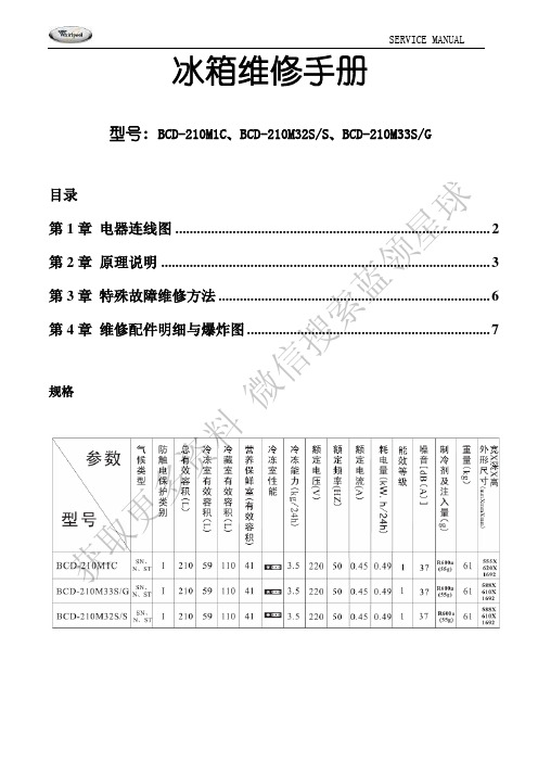
冰箱维修手册型号: BCD-210M1C、BCD-210M32S/S、BCD-210M33S/G目录第1章 电器连线图........................................................................................ 2第2章 原理说明 ............................................................................................ 3第3章 特殊故障维修方法............................................................................ 6第4章 维修配件明细与爆炸图 (7)规格获取更多资料微信搜索蓝领星球第1章电器连线图球星领蓝索搜信微料资多更取获第2章 原理说明1、制冷系统原理说明该系列冰箱制冷系统都是先冻后藏,为单循环直冷系统:压缩机排出的高温高压气态R600a 制冷剂先后进入左冷凝器、右冷凝器,冷凝后变为中温高压的R600a 气液混合制冷剂,由干燥过滤器滤去水分和杂质后进入毛细管,经过毛细管节流降温,变为低温低压汽液混合态制冷剂进入冷冻蒸发器,而后再进入冷藏蒸发器,吸收冷冻室和冷藏室内的热量后变为低温低压气态制冷剂,通过回气管回到压缩机,经过压缩后再排出高温高压的气态制冷剂,如此反复循环。
制冷循环示意图如下:2、控制原理图说明2.1灯开关灯开关为常闭开关,当冰箱开门时,灯开关闭合,冷藏室照明灯点亮;当冰箱关门时,灯开关断开,冷藏室照明灯熄灭。
2.2温控器工作原理该类冰箱采用带有0档停机的单刀单掷温控器,温控器的感温管一般紧贴冷藏蒸发器,当冰箱温度较高时,温控器接通压缩机回路,随着冰箱的不停运转,冷藏蒸发器逐渐变冷,冰箱温度逐渐降低,当蒸发器的温度达到温控器的关机点时候,温控器断开压缩机回路。
Delfield 国际200和300系列冰箱服务和安装手册说明书
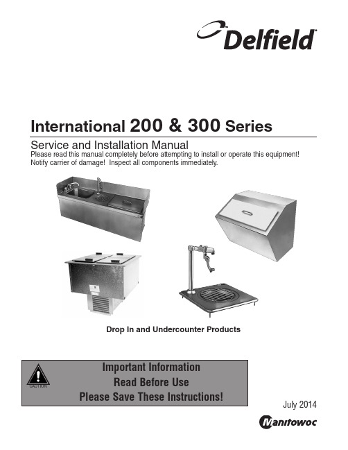
International 200 & 300 SeriesService and Installation ManualPlease read this manual completely before attempting to install or operate this equipment! Notify carrier of damage! Inspect all components immediately.Drop In and Undercounter ProductsJuly 2014International 200 and 300 Series Service and Installation ManualFor customer service, call (800) 733-8829, (800) 733-8821, Fax (989) 773-3210, 2International 200 and 300 Series Service and Installation Manual3For customer service, call (800) 733-8829, (800) 733-8821, Fax (989) 773-3210, Receiving And Inspecting Equipment ........................................3Serial Number Information ........................................................4Warranty Information .................................................................4Regulatory Certifications ............................................................4Specifications .............................................................................5Installation ...............................................................................6-7Operation ....................................................................................8Maintenance ...............................................................................8Wiring Diagram ..........................................................................9Replacement Parts ................................................................9-10Standard Labor Guidelines (11)Even though most equipment is shipped packaged, care should be taken during unloading so the equipment is not damaged while being moved into the building.1. Visually inspect the exterior of the package and skid or container. Any damage should be noted and reported to the delivering carrier immediately.2. If damaged, open and inspect the contents with the carrier.3. In the event that the exterior is not damaged, yet upon opening, there is concealed damage to the equipment notify the carrier. Notification should be made verbally as well as in written form.4. Request an inspection by the shipping company of thedamaged equipment. This should be done within 10 daysfrom receipt of the equipment.5. Visually inspect the refrigeration package. Be sure lines are secure and base is still intact.6. Freight carriers can supply the necessary damage formsupon request.7. Retain all crating material until an inspection has beenmade or waived.International 200 and 300 Series Service and Installation ManualFor customer service, call (800) 733-8829, (800) 733-8821, Fax (989) 773-3210, 4Models Serial Tag LocationN225-E, N227-E On the compressor stand next to the temperature control 203, 204, 204P , 248, 250, 305On the bottom of the ice chests240On the back242On the bottom of the sink 307Underneath the topAlways have the serial number of your unit available when calling for parts or service.©2014 The Delfield Company. All rights reserved. Reproduction without written permission is prohibited. “Delfield” is a registered trademarks of The Delfield Company.Visit/minisite/service/warranty_info to:• Register your product for warranty.• Verify warranty information.• View and download a copy of your warranty.International 200 and 300 Series Service and Installation Manual5For customer service, call (800) 733-8829, (800) 733-8821, Fax (989) 773-3210, MODELLDHSHIP WEIGHTCUTOUT SIZE CABINET CAPACITYH.P .AMPVOLTPLUGDESIGN LOAD BTUSYSTEM CAP . BTUEVAP BTU/TD/TEMPDROP-IN FREEZERSN225-E16.56” (42.1cm)27.87” (70.8cm)26.75” (67.9cm)115lbs (52kg)25.75” x 14.62” (65.4cm x 37.1cm) 6 gal.1/5 1.1230-240CEE 7/729241120/20°/-23°N227-E 30” (76.2cm)27.87” (70.8cm)26.75” (67.9cm)191lbs (87kg)25.75” x 28.00” (65.4cm x 71.1cm)12 gal.1/4 1.7230-240CEE 7/747353228/19°/-22DROP-IN FREEZERS WITH LEXAN ® LIDN225L-E16.56” (42.1cm)27.87” (70.8cm)26.75” (67.9cm)115lbs (52kg)25.75” x 14.62” (65.4cm x 37.1cm) 6 gal.1/5 1.1230-240CEE 7/729241120/20°/-23°N227L-E 30” (76.2cm)27.87” (70.8cm)26.75” (67.9cm)191lbs (87kg)25.75” x 28.00” (65.4cm x 71.1cm)12 gal.1/4 1.7230-240CEE 7/747353228/19°/-22DROP-IN WATER STATIONS AND ICE STORAGE203ice chest20.25” (51.4cm)20.25” (51.4cm)23.25” (59.1cm)52lbs (24kg)19.25” x 19.25” (48.9cm x 48.9cm)90lbs (41kg)N/A N/A N/A N/A N/A N/A N/A204water and ice station 24” (61.0cm)21” (53.3cm)23.5” (59.1cm)47.5lbs (22kg)21” x 17.75”(53.3cm x 45.1cm)45lbs (20kg)N/A N/A N/A N/A N/A N/A N/A204P water and ice station 24” (61.0cm)21” (53.3cm)27” (68.6cm)47.5lbs (22kg)21” x 17.75”(53.3cm x 45.1cm)45lbs (20kg)N/A N/A N/A N/A N/A N/A N/A240ice chest with cover 21” (53.3cm)17.5” (44.5cm)17” (43.2cm)36lbs (16kg)—75lbs (34kg)N/A N/A N/A N/A N/A N/A N/A248water and ice station 31” (78.7cm)15” (38.1cm)22.5” (57.2cm)28lbs (13kg)28” x 12.5”(71.1cm x 31.8cm)45lbs (20kg)N/A N/A N/A N/A N/A N/A N/A305ice chest with cover 21.25” (54.0cm)15.25” (38.7cm)13” (33.0cm)18lbs (8kg)12.5” x 17.75” (31.8cm x 45.1cm)45lbs (20kg)N/A N/A N/A N/A N/A N/A N/A307glass filler12” (30.5cm)12” (30.5cm)9.5” (24.1cm)7lbs (3kg)9.00” x 9.00” (23cm x 23cm)—N/A N/A N/A N/A N/A N/A N/AUNDERCOUNTER SINKS, WATER STATIONS AND ICE STORAGE242UC sink & faucet18” (45.7cm)13.5” (34.3cm)12.75” (32.4cm)20lbs (9kg)17” x 12.5”(43.2cm x 31.8cm)—N/A N/A N/A N/A N/A N/A N/A250UC sink, ice chest and water station 46” (116.8cm)14.06” (36cm)22.75” (57.8cm)81lbs (37kg)45” x 13” (114.3cm x 33.0cm)45lbs (20kg)N/A N/A N/A N/A N/A N/A N/AInternational 200 and 300 Series Service and Installation ManualFor customer service, call (800) 733-8829, (800) 733-8821, Fax (989) 773-3210, 6LocationUnits in this manual are intended for indoor use only. The refrigeration system has been factory tested and should require no further adjustment during installation. For the most efficient refrigeration, be sure to provide good air circulation inside and outside the unit.Outside Cabinet: Be sure that the unit has access to ample air. Avoid hot corners and locations near stoves and ovens.Counter CutoutsFor installation provide a cutout in the counter as shown (see illustration 1 or 2). The counter must be sturdy enough to hold the combined weight up to 300 pounds of the drop-in and the product stored inside.Illustration 1. Model N225-E & N225L-E cutout dimensionsIllustration 3. N225-E N225L-E N227-E & N227L-E louver installationElectrical ConnectionR efer to the amperage data, the serial tag, your local code or the National Electrical Code to be sure the unit is connected to the proper power source. A protected circuit of the correct voltage and amperage must be run for connection of the line cord.If the unit does not operate after it is plugged in, check the thermostat to see if it was inadvertently turned OFF during installation.The unit must b e disconnected from the power source whenever performing service or maintenance functions.The louver provided must be installed in front of the condensing unit’s finned coil (see illustration 3). A second cutout must be made at the rear or end of the equipment to allow air flow through the unit. No louver is provided for the second cutout. Any restriction to the proper air flow, total or partial, will void the compressor warranty.NOTE: A second cutout (without louver) must also be made to allow proper air flow.N225 N225L N227International 200 and 300 Series Service and Installation Manual7For customer service, call (800) 733-8829, (800) 733-8821, Fax (989) 773-3210, LocationUnits in this manual are intended for indoor use only.Avoid hot corners and locations near stoves and ovens.Counter CutoutsFor installation, provide a cutout in the counter sized according to the chart below. The counter must be sturdy enough to hold the combined weight up to 300 pounds of the drop-in and the product stored inside. When mounting a 203 ice chest into a wood counter secure it with provided clips. When mounting into astainless steel counter, use silicone.Mounting StudsEquipment with mounting studs are pictured below. Mark the stud locations according to the measurements or place the equipment in the cutout to mark the stud locations. Drill 0.37” (1.0cm) diameter holes through the counter for the studs.DrainProvided 1” (2.5cm) drain, nut and washer must be field installed to an appropriate container or floor drain following local code requirements. Sinks come standard with 1-1/2” basket strainer assemblies.Water ConnectionAll 1/2” (1.3cm) IPS water inlets must be field connected following local code requirements.M o d e l N u m b e rD e s c r i p t i o nC u t o u t S i z eM o u n t i n g S t u d s1/2” I P S W a t e r H o o k u pD r a i n203ice chest19.25” x 19.25” (49cm x 49cm)N/A N/A (1) 1”204water and ice station 21” x 17.75”(53cm x 45cm)41(2) 1”204P water and ice station 21” x 17.75” (53cm x 45cm)41(2) 1”240ice chest with cover N/AN/A N/A (1) 1”242UC sink & faucet17” x 12.5” (43cm x 32cm)N/A 2(1) 1-1/2”248water and ice station 28” x 12.5”(71cm x 32cm)41(2) 1”250UC sink, ice chest and water station 45” x 13”(114cm x 33cm)N/A 3(2) 1” (1) 1-1/2”305ice chest with cover 12.5” x 17.75” (32cm x 45cm)4N/A (1) 1”307glass filler9.00” x 9.00” (23cm x 23cm)41(1) 1”International 200 and 300 Series Service and Installation ManualFor customer service, call (800) 733-8829, (800) 733-8821, Fax (989) 773-3210, 8After installation, the unit will begin operating simply by plugging it into the proper outlet. If the unit does not operate after being plugged in, check to see if the thermostat is in the OFF position.The models 225-E and 227-E are designed to hold frozen products at a temperature range of 5°F to -5°F (-15°C to -21°C). The thermostat is located in the machine compartment.Never hose down interior or exterior of units with water. This will void the warranty. Wipe interior dry of any water accumulation.In order to maintain proper refrigeration performance,the condenser fins must be cleaned of dust, dirt and grease every three months. If conditions are such that the condenser is totally blocked in three months, the frequency of cleaning should be increased.Clean the condenser with a vacuum cleaner or stiff brush. If extremely dirty, a commercially available condenser cleaner may be required.Defrosting must be done manually after 3/8” of ice accumulation. T o defrost disconnect power to theequipment or turn the thermostat knob to the OFF position.The lid should be cleaned regularly with a soft cloth or sponge and solution of soap and water to maintain it’s ability to seal properly.Never hose down interior or exterior of units with water. This will void the warranty. Wipe interior dry of any water accumulation.The interior and exterior of these models may be cleaned using soap and warm water. If this is not sufficient, try ammonia and water or a non-abrasive cleaner. Be sure to rinse thoroughly with clean water after using ammonia or a cleaner. When cleaning the exterior, always rub with the “grain” of the stainless steel to avoid marring the finish.International 200 and 300 Series Service and Installation Manual9For customer service, call (800) 733-8829, (800) 733-8821, Fax (989) 773-3210, Key Part No.Description 13234188Cover (solid)3234189Cover (see-through)21701273Trim gasket 33516172Fan blade 43516067Condensing coil 52162692Fan motor, 240V, 50/60Hz 6031-264-0000Fan motor bracket73516230Filter dryer, double 1/4”OD inlet, 225-E3516322Filter dryer, 227-E 83516452 Compressor relay, 225-E 3516453Compressor relay, 227-EKey Part No.Description 93516451 Start capacitor103526994225-E Compressor, 1/5 H.P . 220/50, R404A, TL4CL3527013227-E Compressor, 1/4 H.P . 220/50, R404A, NL7CLX 11MCP00143Control Temperature, 227-E -Purchase locally Capillary tube, .031” i.d. 120”, 225-E -3516596Expansion Valve, 227-E -Varies per destination Harness, power cord-3516324High pressure cutout-359-411-0003Louvered panel (cutout 12” x 23.5”Power Supply230-240V/50 Hz/1øInternational 200 and 300 Series Service and Installation ManualFor customer service, call (800) 733-8829, (800) 733-8821, Fax (989) 773-3210, 10Model 203Models 204 And 204P000-AUO-0030 Removable lid with handle 3234110 Lid handle 9321406 Lid handle screw 3234242 Drain3234088 Glass filler 9.5” high, max. ht glass 8”3234303 Pitcher filler 13.5” high, max. ht pitcher 12”3234242 Drain (ice chest and water filler)000-AUO-0030 Removable lid with handle 3234110 Lid handle 9321406 Lid handle screw 3977953 GuardModel 2423234007 Basket Strainer 3234076FaucetModel 2483977953 Guard 3234088 Glass filler 3234242 Drain 000-AUO-0030 Removable lid 3234110 Lid handle 9321406 Lid handle screwModel 240000-AUO-0001 Removable lid 3234110 Lid handle9321406 Lid handle screws 3234242DrainModel 2503234007 Basket strainer3234076 Faucet 000-AUO-0030 Removable lid 3234110 Lid handle 9321406 Lid handle screw 3234088 Glass filler 3234242 Drain 3977953 GuardModel 305Model 3073234242Drain000-AUO-0030 Removable lid 3234110 Lid handle9321406Lid handle screw3234088 Glass filler 9.5” high, max. ht glass 8”3977953 Guard 3234242 DrainInternational 200 and 300 Series Service and Installation Manual11For customer service, call (800) 733-8829, (800) 733-8821, Fax (989) 773-3210, Advice and recommendations given by Delfield Service Technicians do not constitute or guarantee any special coverage.• A maximum of 1-hour is allowed to diagnose a defective component .• A maximum travel distance of 100 miles round trip and 2-hours will be reimbursed. Actual travel to be charged.• Overtime, installation/start-up, normal control adjustments, general maintenance, glass breakage, freight damage, and/or correcting and end-user installation error will not be reimbursed under warranty unless pre-approved with a Service Work Authorization from Delfield. You must submit the number with the service claim.• Actual repair time will be paid at or below guidline.• Parts on the critcal stock list must be air freighted at the expense of the service agent.Labor Up To 1-Hour Is Allowed To Replace• Infinite Switch• Contactor/Relay • Door Jamb Switch• Transformer • Solenoid Coil• Evaporator/Condenser Fan Motor and Blade • Hi-limit/Thermal Protector Switch• Circulating Fan Motor and Blade • Fan Delay/Defrost Termination Switch• Digital Control • Compressor Start Components and Overload Protector• Water Level Sensor/Probe • Defrost Timer• Door Hinges, Locks, and Gaskets • Thermostat• Condensate Element • Thermometer• Springs/Lowerator• Gear MotorLabor Up To 2 Hours To Replace• Drawer Tracks/Cartridges• Defrost Element • Pressure Control• Heating Element • Solenoid Valve• Locate/Repair Leak Labor Up To3 Hours To Replace• EPR or CPR Valve• Condenser or Evaporator Coil • Expansion Valve • Cap Tube Labor Up To 4 Hours To Replace• Compressor-This includes recovery of refrigerant and leak check.-$55.00 maximum reimbursement for refrigerant recovery (includes recovery machine, pump, torch, oil, flux, minor fittings, solder, brazing rod, nitrogen, or similar fees).Refrigerants• R22 A maximum of $4.00/lb. or 25¢/oz. will be reimbursed.• R134A A maximum of $7.00/lb. or 44¢/oz. will be reimbursed.• R404A A maximum of $16.00/lb. or $1.00/oz. will be reimbursed.Mt. Pleasant, MI Covington, TN 980 S. Isabella Rd., Mt. Pleasant, MI 48858, U.S.A. • (989) 773-7981 or (800) 733-8829 • Fax (989) 773-3210 • Delfield reserves the right to make changes in design or specifications without prior notice. ©2014 The Delfield Company. All rights reserved. Printed in the U.S.A.DM200_300int 07/14Part Number Thank you for choosing Delfield!Help is a phone call away. Help our team of professional, courteous customer service reps by having your model number and serial number available at the time of your call (800) 733-8829.Model: _______________________S/N: ______________________Installation Date: _______________For a list of Delfield’s authorized parts depots,visit our website at 。
Electrolux BCD-260EI电冰箱 维修手册
2)灯开关: 冷藏室和酒室的门灯开关为磁力感应开关,冷藏室的
磁力感应开关直接卡装在顶盖的前部,拆装方便,而
酒室的感应开关则埋在箱体的门框内,不可更换。它
们靠装在相应门上的磁铁来达到开门灯亮,关门灯灭
的作用。 检测好坏时可用磁铁的靠近与分离,来测量两根
传感器温度
电阻值
+20℃
~ 4 KΩ
+10℃
~ 5.4 KΩ
+5℃
~ 6.8 KΩ
-20℃
~ 25 KΩ
-30℃
~ 47 KΩ
六、R600a 制冷剂排气以及抽空加注的方法
1、维修场地的要求 维修场地必须是平坦宽敞通风的,不准设在地下室及其它较封闭不通风的地方
以保持场地空气流通,
④用管割刀割开工艺管口,套上三通阀表,注入小于 0.4Mpa 压力的氮气进行清洗,此
时将毛细管口修剪圆整。
2 分钟后关闭氮气阀,并撤离排空钳、三通阀表,进行焊接和更换压缩机。
⑤更换焊接完毕后,在压缩机工艺管上和双头过滤器端的工艺管分别接上三通阀表。在
压缩机工艺管端缓慢注入 0.8Mpa 的氮气对焊接点进行检漏。确认不漏后排掉氮气进
四、控制面板及其说明
1: 锁定图标。按住下调键(22)5 秒以上,显示屏上出现锁定图标,所有按键被锁定,反之取消。
2: 快速冷藏键,按下后显示屏显示 图标,冷藏室按+2℃设置运行,压缩机提速运行,6 小时 后自动退出快速冷藏。6 小时内也可手动退出。
3: 快速冷藏图标 4: 时钟/存放温度及天数。通常情况下为时间显示,在食品管理模式中则分别为推荐食物的最佳储
毛细管上有一小段黑色标记的为冷藏室系统。 毛细管上没有颜色标记的为冷冻室系统。
冰箱维修手册
冰箱维修手册第一章:常见问题及解决方法1. 冰箱不能正常开启a) 确保电源线插头已正确插入电源插座。
b) 检查电源插座是否正常工作,可试插其他电器设备进行确认。
c) 检查冰箱的保险丝是否烧断,如有需要更换保险丝。
2. 冰箱无法制冷或制冷效果不佳a) 检查温度调节器是否设置正确,通常应设置在适宜的冷藏温度范围内。
b) 清理冰箱背后的散热器,确保良好的散热效果。
c) 检查冰箱门是否密封良好,如发现密封条松动、破损,则需要更换密封条。
d) 检查冰箱背后的压缩机是否正常运转,如发现异常,建议联系专业维修人员进行处理。
3. 冰箱有噪音或震动a) 检查冰箱的平衡性,确保冰箱放置在平稳的地面上。
b) 检查冰箱底部的调脚螺丝是否松动,如有需要,调整螺丝使冰箱保持水平稳定。
c) 检查冰箱内部的物品是否摆放整齐,避免碰撞和共振产生噪音。
4. 冰箱出现漏水a) 检查冰箱内部的排水孔是否堵塞,如发现堵塞,使用软管进行清理。
b) 检查冰箱的水箱是否装满水或冰块,及时排空或清除。
第二章:常用维修工具和材料1. 扳手:用于拆卸冰箱部件和紧固螺丝。
2. 螺丝刀:用于拆卸和安装螺丝。
3. 漏氟检测仪:用于检测冰箱是否有制冷剂泄漏。
4. 温度计:用于测量冰箱的温度。
第三章:维修步骤1. 切断冰箱的电源,确保安全。
2. 根据问题的性质,选择相应的维修工具和材料。
3. 根据冰箱的使用说明书,确定拆卸和安装部件的步骤。
4. 逐步检查冰箱的电路连接、制冷系统、散热器等部件,并进行相应的维修或更换。
5. 维修完成后,将冰箱的各部件安装好,并确保连接紧固。
6. 接通冰箱的电源,并进行功能测试。
第四章:安全注意事项1. 在维修冰箱时,务必切断电源,以避免触电事故。
2. 若对维修步骤不了解或遇到复杂故障,建议寻求专业维修人员的帮助。
3. 维修过程中,要注意观察和记录问题现象和维修步骤,以便更好地解决类似问题。
结语:本手册提供了一些常见问题的维修方法和步骤,但并不能包括所有可能的故障情况。
冰箱维修 冰箱常见故障分析 电冰箱如何维修

冰箱维修冰箱常见故障分析电冰箱如何维修冰箱维修冰箱常见故障分析电冰箱如何维修[冰箱维修]冰箱常见故障分析电冰箱如何维修冰箱就是家庭中少数持续运转的电器之一。
它夜以继日地工作,并使您的食物维持在低温状态。
如果您考虑过冰箱的工作存有多艰辛,您就可以真的它们没频密地出来故障真的就是一件令人惊讶的事。
但冰箱偶尔也可以暂停工作,这时您可能会必须缴付高昂的修理费用,还要出钱再次卖过所有的食物。
不过别担心,本文将告诉您在自行修理冰箱和冷冻箱时所须要的一切科学知识。
您可能会吃惊地辨认出,修理其实相当难,只要有一点关于电器的科学知识和一点冷静就这么了。
使我们先从一些基本知识已经开始。
电冰箱的散热器装置;每台电冰箱都存有散热器,1、有的加装在电冰箱的后背呈网片状,2、封闭式的电冰箱则它就是轻易挂上了冰箱周围外皮的内壁上,这2种方法,若在后面看不出散热器网片这种就一定就是后一种精心安排形式。
后种我们在开机后就可以捏至电冰箱外皮左右就是咳嗽的,(特定的除了在电冰箱的底部串联一个"冷却"装置,为的是能够把机箱内流入的排洪尽快蒸发掉。
为什么电冰箱的门周围会发热;(除露管装置)电冰箱在开机时,你用手回去牵捏箱体门封的周围可以辨认出都就是很热的,原来这就是厂家有意思设计的缘故,由于电冰箱内部很冷,又当外部气温低时门口就可以发生"汗珠"耐酸碱现象,所以设计人员都把压缩机出口的气体管路顺带先紧紧围绕门口一周,利用管路的热量顺带驱离掉耐酸碱构成的水珠(这一段管路缩写为'门封管',也叫做门封除露管)。
冰箱噪音大的故障检测流程1、外部因素:底角不平,检测地面不平,指导用户用底角扳手调整冰箱底角,并使冰箱处在水平边线;冰箱和其他物品碰到或靠墙,指导用户将相依靠的物品松开或将冰箱墙壁维持一定距离;蒸发皿或冷凝器收紧,指导用户将冷凝器或蒸发皿套管。
Electrolux 冰箱维修手册说明书

SERVICE MANUALREFRIGERATION ©Electrolux Home Products S.p.A.Spares Operations ItalyCorso lino Zanussi, 30I - 33080 Porcia (PN)Fax +39 0434 394096S.O.I.Edition: 11.2006Publication no.599 38 43-56ENREFRIGERATORSwithelectric valveandelectronicERF2000DIGITSFACTORY: ZSCONTENT1INTRODUCTION (3)2REFRIGERATION CIRCUIT (5)3ELECTRIC WIRING (6)4COMPONENTS (8)4.1Control panel (8)4.2Electronic boards (9)4.2.1 ERF2000 Power board (10)4.2.2 ERF2000 DIGITS Display board (12)4.3Cooler and freezer compartments (13)4.3.1 Temperature sensors (14)4.3.2 Door switch (14)4.4Compressor compartment (14)4.4.1 Electric valve (15)5MAIN FUNCTIONS (16)5.1Normal (16)5.2FROSTMATIC Function (rapid freezing) (17)5.3COOLMATIC Function (rapid cooling) (17)5.4HOLIDAY Function (valid only for the cooler) (17)5.5Malfunctioning of cooler air temperature sensor (18)5.6Malfunctioning of freezer temperature sensor (19)6ALARMS (20)6.1Freezer compartment temperature alarm (20)7SPECIAL FUNCTIONS (21)7.1Service Mode (21)7.1.1 Starting Service Mode (21)7.1.2 Exiting Service Mode (21)7.1.3 Functions of the Service Mode (21)7.2DEMO MODE (23)7.2.1 Start DEMO MODE (23)7.2.2 Exit DEMO MODE (23)7.2.3 Functions of the DEMO MODE (23)8ACCESSIBILITY (24)8.1Control panel (24)9DISPLAY SYMBOLS (25)9.1Cooler compartment (25)9.2Freezer compartment (26)1INTRODUCTIONThis manual describes the refrigerators with electric valve and ERF2000 DIGITS electronic produced in the Susegana factory called ZS.These models feature:-static (static freezer, static cooler)-total built-in-DOOR ON DOOR door system-single-compressor-electronic control (electronic board ERF2000)-electric valve-digit displayThey are appliances (KBI290DVIT) with the following PNCs:PNC MODEL BRAND925701653JKG9499Juno-Electrolux925701654SC91840-5I AEG-Electrolux925701655SC81840-5I AEG-Electrolux925701656SC81840-5I AEG-Electrolux925701659ERO2923Electrolux925701660ERO2924Electrolux925701661JKG9499Juno-Electrolux925701662SC91840-5I AEG-Electrolux925701663SC91843-5I AEG-Electrolux925701664463.688-2Privileg925701665ERO2923Electrolux925701666ERO2923Electrolux925701667DRC629JE De Dietrich925701668IKE318-5-2Küppersbusch925701669DRC629JE De Dietrich925701670IKE318-5-2Küppersbusch925701671JCG94180Juno-ElectroluxThe controls of the appliance are inserted inside the upper crosspiece.The power control board is ERF2000.The user interface board is ERF2000 (DIGIT display).The appliance has a single-compressor and an electric valve is installed to simulate the operation of a two-compressor.It is possible to switch off only the cooler compartment and let the freezer operate, but not vice versa.The temperatures regulation is the following:•from +8 to +2 °C for the cooler;•from -15 to -24 °C for the freezer.The DIGIT display enables to show the temperatures of the two compartments. The appliance has the following functions:•rapid freezing;•rapid cooling;•freezer temperature alarm,•cooler compartment holiday.The appliance consists of the following compartments:•freezer;•cooler.The evaporating circuit consists of:•roll bond plate evaporator (freezer);•tube evaporator (cooler compartment).Key:A = control panelB = cooler compartmentC = freezer compartment2REFRIGERATION CIRCUITKey:pressor;2.condenser;3.anti-condensation coil;4.dehydrator filter;5.electric valve;6.tube evaporator (cooler compartment);7.plate evaporator (freezer compartment);8.exchanger.The electric valve has 2 outlet capillaries to power:•cooler + freezeror•only the freezer.3ELECTRIC WIRING(Check the specific diagram for each model!)Key:pressormp31.electric valve28.running capacitor (if featured) 41.ERF2000 power boarda.yellow-greenb.brownc.blued.whitee.black4COMPONENTS4.1Control panelKey:Cooler compartmentA.cooler ON/OFF indicator LEDB.cooler ON/OFF buttonC.cooler temperature increase button (+)D.cooler temperature displayingE.cooler temperature decrease button (-)F.COOLMATIC Function LED (rapid cooling)G.COOLMATIC function button (rapid cooling)Freezer compartmentH.ON/OFF indicator LED refrigeratore+freezerI.ON/OFF button cooler+freezerJ.freezer temperature increase button (+)K.freezer temperature displayingL.freezer temperature decrease button (-)M.FROSTMATIC Function LED (rapid freezing) N.FROSTMATIC function button (rapid freezing) O.alarm pilot lamp LEDP.alarm deactivation button4.2Electronic boardsThe electronic board of the appliance consists of:1.ERF2000 power board2.ERF2000 DIGITS display boardThe two electronic boards are connected by means of a flat cable with a connector; therefore, the two boards are available singularly as spare part.4.2.1ERF2000 Power board- View of the electronic board (side of components):1.earth contact2.free3.linepressor5.neutralmp neutralmp8.neutral electric valve9.electric valve1.free2.free1.cooler air temperature sensor2.cooler air temperature sensor3.cooler evaporator temperature sensor4.cooler evaporator temperature sensor5.freezer air temperature sensor6.freezer air temperature sensor1.free2.free1.free2.free3.free4.free1.free2.free4.2.2ERF2000 DIGITS Display boardKey:SW1= reed elementSW2= ON/OFF button cooler+freezerSW3= FROSTMATIC function button (rapid freezing) SW4= freezer temperature increase button (+)SW5= freezer temperature decrease button (-)SW6= cooler ON/OFF buttonSW7= COOLMATIC function button (rapid cooling) SW8= cooler temperature increase button (+)SW9= cooler temperature decrease button (-)SW10= alarm deactivation buttonDGT1= cooler displayDGT2= freezer displayDL1= COOLMATIC function LED (rapid cooling)DL2= FROSTMATIC function LED (rapid freezing) DL3= alarm pilot lamp LEDDL4= LED sign + coolerDL5= ON/OFF indicator LED coolerDL6= LED sign - freezerDL7= ON/OFF indicator LED cooler+freezer4.3Cooler and freezer compartmentsKey:A.freezer air temperature sensor;B.cooler air temperature sensor;C.cooler evaporator temperature sensor.1.cooler door magnet;2.display board reed element.4.3.1Temperature sensors3 NTC sensors are used to detect the temperatures of the two compartments:•freezer air temperature sensor A (located on the freezer cell);•cooler air temperature sensor B (located on the cooler cell);•cooler evaporator temperature sensor C (located on the cooler cell).The sensors A, B and C feature the foamed cable inside the cabinet, therefore they are not replaceable (for further information, please see Service Bulletin 599374122).4.3.2Door switchThe control of the cooler door opening is carried out by using the magnetic switch located on the display board. The magnetic switch is activated by a magnet located inside the cooler door.The control does not imply the activation of the open door alarm, but it is used to light up the lamp of the cooler compartment.4.4Compressor compartmentKey:pressorB.electric valve4.4.1Electric valveThe electric valve is of the 3-way bistable type.It is supplied together with the dehydrator filter.The connections of the electric valve are the following:-central hose with dehydrator filter to connect the condenser;-side hose (GS) to connect the capillary of the freezer circuit;-side hose (KS) to connect the capillary of the cooler+freezer circuit.The electric valve has the following values:-voltage 220 V - 50 Hz-response time <1 secNote:Comply with the electric connections and do not invert the polarity (the 2 terminals FAST-ON have different dimensions).5MAIN FUNCTIONS5.1NormalIn case of first switching on with a freezer compartment temperature higher than 10 °C, the appliance operates with a test cycle (for the factory) for a maximum time of about 1,5 hours.In this period do not perform tests for the correct operation of the appliance, since the loads of the appliance are activated only for internal check (compressor and electric valve).When the appliance is off then:•the compressor is off;•the displays are off.Pushing the ON/OFF button, the displays switch on with the following displaying:•+ symbol on cooler display;•flashing digits of the freezer;•freezer temperature alarm LED (buzzer active).Push the alarm deactivation button to deactivate the buzzer.Regulate the temperatures of the compartments so as to set the following values:•about +5 °C in the cooler;•about -18 °C in the freezer.Warning: Unplug the appliance before operating.5.2FROSTMATIC Function (rapid freezing)The FROSTMATIC function (rapid freezing) is activated by pushing the relative button, therefore:•The pilot lamp relative to the FROSTMATIC function lights up;•The compressor operates in thermostatic conditions and not continuously (like the temperature knob was on max. position) for a duration of about 52 hours, and then it deactivates automatically.To deactivate the FROSTMATIC function push the relative button.5.3COOLMATIC Function (rapid cooling)The COOLMATIC function (rapid cooling) is activated by pushing the relative button, therefore:•The pilot lamp relative to the COOLMATIC function lights up;•The compressor operates in thermostatic conditions and not continuously (like the temperature knob was on max. position) for a duration of about 6 hours, and then it deactivates automatically.To deactivate the COOLMATIC function push the relative button.5.4HOLIDAY Function (valid only for the cooler)The HOLIDAY function is activated when the customer does not want to use temporary the cooler.In this case it is not necessary to leave the cooler door open, because a 15 °C temperature is automatically set to avoid the formation of bad odours inside.To activate the HOLIDAY function push button + (temperature increase) till letter H is shown in the cooler dis-play.Obviously the cooler must be empty because the 15 °C temperature does not allow the preservation of the most common food.the sensor is out of range), then:When the sensor operates again normally, the above described conditions terminate.Characteristics of the NTC sensor:•The display shows cooler temperature sensor faulty.•The appliance operates with preset cycle when the compressor is powered for 40 minutes andremains off for 40 minutes alternatively.the sensor is out of range), then:When the sensor operates again normally, the above described conditions terminate.Characteristics of the NTC sensor:•The display shows freezer temperature sensor faulty.•The appliance operates with preset cycle when the compressor is powered for 40 minutes andremains off for 40 minutes alternatively.6ALARMS6.1Freezer compartment temperature alarmWhen the freezer compartment reaches -11 °C, the temperature alarm activates:•The display digits flash.•The temperature alarm pilot lamp light up.•The buzzer sounds.Push the alarm deactivation button to deactivate the buzzer.When normal conditions are reset (after a power failure):•The acoustic signal deactivates.•The temperature alarm pilot lamp remains on.•The display digits still flash.Pushing the alarm deactivation button:•The highest temperature reached in the freezer compartment is displayed for 5 minutes.•The alarm pilot lamp switches off.•The display digits do not flash anymore.7SPECIAL FUNCTIONS7.1Service Mode7.1.1Starting Service ModeTo start the procedure, perform the following operations:1.Connect the plug to the socket.2.Switch on the appliance with the ON/OFF button.3.Open the doors of the appliance.4.Switch the appliance off with the ON/OFF button.5.Within the first 10 seconds hold down simultaneously the two buttons “FROSTMATIC function (rapid freez-ing)” and “alarm deactivation”.The confirmation of the procedure start occurs with the acoustic signalling of the buzzer which emits a long beep and with the lighting up of all segments of the display.7.1.2Exiting Service ModeThe procedure terminates when one of the following operations is carried out:a.The plug is detached from the socket and reconnected.b.40 minutes have elapsed and no button has been pushed.c.The last phase of the procedure has been reached.7.1.3Functions of the Service ModePress the button “FROSTMATIC function (rapid freezing)” or “alarm deactivation” to skip to the following phase of the procedure.Prsss the “ON/OFF” button to activate/deactivate the loads (compressor, defrosting heater, lamp, fan and air flow regulator damper).List of the phases of the SERVICE MODE:1.All segments of the display are on.2.All segments of the displays are off.3.The number 0 is shown on the display and the load controlled by ACS TH1 [compressor] is checked.To activate/deactivate the load press the button “ON/OFF” (the load is activated when the rapid freezing FROSTMATIC function pilot lamp and the alarm pilot lamp light up).4.The number 1 is shown on the display and the load controlled by ACS TH2 [electric valve] is checked.To activate/deactivate the load press the button “ON/OFF” (the electric valve switches from one side to the other and it is possible to hear a click).5.The number 2 is shown on the display and the laod controlled by ACS TH3 [lamp] is checked.To activate/deactivate the load press the button “ON/OFF” (the load is activated when the rapid freezing FROSTMATIC function pilot lamp and the alarm pilot lamp light up).6.The number 3 is shown on the display and the load controlled by ACS TH4 [not used in this appliance] ischecked.To activate/deactivate the load press the button “ON/OFF” (the load is activated when the rapid freezing FROSTMATIC function pilot lamp and the alarm pilot lamp light up).Note:When the procedure skips to the following phase pressing the button “FROSTMATIC function (rapid freez-ing)” or “alarm deactivation”, the laod keeps its status (for example, if the compressor had been activated, it will remain on also in the subsequent phases); in this way it is possible to check the loads simultaneously.7.Check of the doors.The display digits correspond to the doors: the unit digits correspond to the cooler door, while the ten digits correspond to the freezer door.If the relative door is closed, the displayed digit is 0 otherwise is 1.8.Check of the counter.The display shows an increasing number at intervals of 1 second.This is a counter used by the board for its internal management.9.Check of the temperature sensors.The display shows one of the following codes:Code DESCRIPTIONE0No errorE1Evaporator sensor damagedE2Room temperature sensor damaged (installed on the display board)E4Room temperature sensor damaged (installed on the power board)E50 degree compartment sensor damagedNote:The errors regarding the cooler and freezer air sensors are already displayed during the normal operation. At this point all the phases necessary to chcek the loads have been displayed, therefore it is advisable to in-terrupt the procedure of the SERVICE MODE unplugging and replugging the appliance.Note:If you do not want to interrupt the SERVICE MODE, the procedure continues with some phases dedicated ex-clusively to the factory, therefore they must not to be considered.Also in this case the exit from the SERVICE MODE is carried out unplugging and replugging the appliance.7.2DEMO MODEThe DEMO MODE function is intended only for the commercial activity and not for the user.The internal temperature of the appliance, measured by the air sensors, must be higher than +10 °C so as the function can be activated.7.2.1Start DEMO MODETo start the procedure, hold down the ON/OFF button cooler+freezer and the freezer temperature decrease button for more than 5 seconds.The display digits flash every about 4 seconds.7.2.2Exit DEMO MODETo exit the procedure, hold down the ON/OFF button cooler+freezer and the freezer temperature decrease but-ton for more than 5 seconds or unplug the appliance.7.2.3Functions of the DEMO MODEThe procedure is used only for show in the selling points and allows selecting the temperatures without acti-vating the loads (compressor and electric valve).The displays show:•+ 5 °C for the cooler compartment (flashing display);•-18 °C for the freezer compartment (flashing display).By pushing the temperature regulation buttons, the displays show the temperatures that can be set (flashing display).The internal light switches on when the cooler door is opened.By pushing the cooler ON/OFF button it is possible to simulate the switching off of the cooler compartment (the lamp is off).8ACCESSIBILITY8.1Control panelTo access the control panel and its components (power and display boards) perform the following operations in sequence:a.Open the cooler door.Warning: Disconnect the appliance from the electric power before operating with theappliance.b) View of the control panel of the upper cross-piece.c) Remove the programme plate removing the 2 screw covers and the 2 fixing screws.d) Remove the transparent foil and extract the con-trol support.e) View of the power board.9DISPLAY SYMBOLS9.1Cooler compartmentDISPLAY DIGITS DESCRIPTIONNOT FLASHING It indicates the cooler temperature with normal function [from +2 to +8].FLASHING It indicates the cooler temperature with DEMO MODE func-tion [from +2 to +8].NOT FLASHING It indicates the HOLIDAY function of the cooler compart-ment [15 °C].NOT FLASHING It indicates the malfunctioning of cooler air temperature sensor.NOT FLASHING It indicates incompatibility between the electronic boards. Remedy: check the spare part nos. of the electronic boards.NOT FLASHING It indicates Eeprom parameter writing/reading error. Remedy: replace both electronic boards (power and dis-play).9.2Freezer compartmentDISPLAY DIGITS DESCRIPTIONNOT FLASHING It indicates the freezer temperature with normal function [from -15 to -24].FLASHING It indicates the freezer temperature with DEMO MODE function [from -15 to -24].NOT FLASHING It indicates the malfunctioning of freezer air temperature sensor.NOT FLASHING It indicates incompatibility between the electronic boards. Remedy: check the spare part nos. of the electronic boards.NOT FLASHING It indicates Eeprom parameter writing/reading error. Remedy: replace both electronic boards (power and dis-play).。
冰箱产品维修指导手册(基础篇)
冰箱产品维修指导手册(基础篇)前言:2010年度,我司将推出冰箱产品,兵马未动,粮草先行,客服部特制定本维修指导手册。
第一章冰箱基础知识第一节电冰箱的定义及分类一个供家用的具有适当容积和装置的绝热箱体,用消耗电能的手段来制冷,并具有一个或多个间室,它包括冷藏箱、冷藏冷冻箱、冷冻箱。
冷藏冷冻箱指至少有一个间室为冷藏室,适用于储藏不需冻结的食品,并至少有一个间室为冷冻室,适用于需要在-18℃或-18℃以下保存的冷冻食品和储藏冷冻食品。
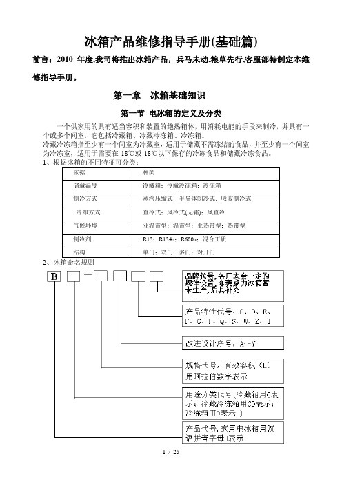
1、根据冰箱的不同特征可分类:依据种类储藏温度冷藏箱;冷藏冷冻箱;冷冻箱制冷方式蒸汽压缩式;半导体制冷式;吸收制冷式冷却方式直冷式;风冷式(无霜);风直冷气候环境亚温带型;温带型;亚热带型;热带型制冷剂R12;R134a;R600a;混合工质结构单门;双门;多门;对开门2第二节电冰箱的结构及主要零部件介绍1、压缩机压缩机是冰箱的心脏部件,是制冷系统完成连续制冷循环的动力装置,其基本功能是将蒸发器中吸收了热量而汽化的制冷剂吸入后,压缩成高压气体送到冷凝器中冷却。
压缩机按工作原理可分为容积型和离心型,容积型是靠工作腔的容积变化实现制冷剂的吸入、压缩和排出,这类压缩机又可按工作腔容积变化方式分为往复式和回转式,冰箱普遍采用的是往复式,靠汽缸和活塞组成工作腔,活塞作直线往复运动;回转式的特点是气缸内有旋转的转子,汽缸与转子间形成工作腔,工作腔随转子的旋转而变化。
离心型是靠离心力的作用,连续吸入、压缩、排出,输送制冷剂蒸汽,其工作原理与离心鼓风机相似,靠高速气流动能的变化来提高气体的压力。
主要配件及参数:压缩机的主要配件有电器附件(过载保护器、PTC起动器)、电器盒盖以及减振胶脚等,电器附件分为标准(分体)两器和整体式两器。
2、冷凝器冷凝器的作用是将高温高压的制冷剂蒸气,通过向周围空气散热,变成中温高压的制冷剂液体。
冷凝器所用材料已由最初的铜管到邦迪管,目前大量使用镀锌钢管,价格低,焊接难度较大。
PTM72R商业冰箱维修手册说明书

Commercial Refrigerator Service ManualSOLID DOOR TOP MOUNT REACH-IN PTM72RPlease read this manual completely before attempting to install or operate this equipment.TABLE OF CONTENTS1. FEATURE CHART1-1. OUTSIDE DRAWING AND MEASUREMENT FOR PTM72R2. WIRING DIAGRAM2-1. REFRIGERATOR (3 DOORS): PTM72R3. PARTS DETAILS3-1. TOP PANEL3-2. REFRIGERATION COMPARTMENT3-3. DOOR3-4. COOLING COMPARTMENT4. MAIN COMPONENTS4-1. COMPRESSOR4-2. COMPRESSOR RELAY4-3. CONDENSER DRYER4-4. CAPACITOR4-5. EVAPORATOR FAN MOTOR4-6. CONDENSER FAN MOTOR4-7. EVAPORATOR DEFROST HEATER4-8. LAMP4-9. THERMOSTAT5. ELECTRONIC CONTROLLER INSTRUCTION5-1. REFRIGERATOR CONTROLLER5-1-1. DIXELL XR20C PARAMETER FOR REFRIGERATOR PTM72R 5-1-2. HOW TO USE THE CONTROLLER6. REPLACEMENT OF MAIN COMPONENTS6-1. BOTTOM PANEL PARTS6-2. REFRIGERATION COMPARTMENT PARTS6-3. CONDENSING UNIT1. FEATURE CHART1-1. OUTSIDE DRAWING OF PTM72R2. WIRING DIAGRAM 2-1. PTM72R3. PARTS DETAILS 3-1. TOP PANELTHERMOSTATMAIN SWITCHDOOR SWITCHLOCK3-2. REFRIGERATION COMPARTMENT CYCLE ASSEMBLYCONDENSER FILTER DRIER CONDENSER FAN MOTOR WATER PAN COMPRESSORDRAIN PANCONDENSER FAN MOTOR ASSEMBLYFAN COVER CONDENSER FAN MOTOR BLADE CONDENSER FAN MOTOR3-3. DOORGASKETMagnetic gasket can be replaced without any tools.3-4. COOLING COMPARTMENTCircle Fan CoverEvaporator Fan Motor Blade Evaporator Fan Motor Fan CoverEvaporator Defrost Heating ElementEvaporator Fan Fan Support4. MAIN COMPONENTS4-9. MAIN PCB5. ELECTRONIC CONTROLLER INSTRUCTION5-1-1DIXELL XR20C PARAMETER FOR NO.15-1-2.T o display target set point, select a parameter or confirm an operation in programmingmode.T o start a manual defrostT o view the last alarm occurrence. In programming mode, it browses the parameter codes or increases the display valueT o view the last alarm occurrence. In programming mode, it browses the parameter codes or decreases the display valueKEY COMBINATIONT o lock & unlock the keyboard T o enter in programming modeT o return to the room temperature display1.1 Function of LEDS2.1 HOW TO VIEW THE SET POINT1. Push and immediately release the SET key: the display will show the set point value.2. Push and immediately release the SET key or wait for 5 seconds to display thesensor value again.2.2 HOW TO CHANGE THE SET POINT1. Push the SET key for more than 2 seconds to change the set point value.2. The value of the set point will be displayed and the LED starts blinking.3. To change the set value, push the or key within 10s.4. To set new point value, push the SET key again or wait 10s.2.3 HOW TO START A MANUAL DEFROSTPush the key for more than 2 seconds and a manual defrost will start2.4 HOW TO LOCK THE KEYBOARD1. Hold the and keys for more than 3s.2. The “POF”message will be displayed and the keyboard will be locked. At this point, it will bepossible only to see the set point or the MAX or Min temperature stored.3. If a key is pressed more than 3s the ”POF” message will be displayed.2.5 HOW TO UNLOCK THE KEYBOARDHold the and keys together for more than 3s, till the “P OF” message is displayed.3.HOW TO VIEW THE ALARM ANDRESET THE RECORDED ALARM1. Hold the or key todisplay the alarm signals.2. When the signal is displayed, holdthe SET key until the “rst” messageis displayed. Push the SET keyagain. The “rst” message will startblinking and the normal temperaturewill be displayed again.6. REPLACEMENT OF MAIN COMPONENTS6-1. FRONT PANEL PARTSUNSCREW THE FRONT PANELA. LIFT THE PANELYou can change the door switch, lock main switch and the thermostat here6-2. REFRIGERATION COMPARTMENT PARTS6-2-1. UNSCREW THE SENSOR CLIP AND TAKE THE SENSOR OUT FROM THE CLIP6-2-2. UNSCREW THE CIRCLE FAN COVER6-2-3. PULL DOWN THE CIRCLE FAN COVER.6-2-4. UNSCREW THE FAN SUPPORT6-2-5. CHANGE THE DEFROST HEATING ELEMENTa. UNHOOK THE EVAPORATOR FROM ITS CASINGb. TAKE OFF THE ELEMENT AND REPLACE IT.6-3. CONDENSING UNIT6-3-1. TAKE OFF THE BOTTOM PANEL OF THE UNIT.6-3-2. UNSCREW THE UNIT BOARD. YOU CAN PULL THE UNIT BOARD OUT FOR ANY REPAIRS OR CLEANING.CAUTION: BE CAREFUL OF ELECTRIC SHOCKCAUTION: MAKE SURE THE POWER SUPPLY IS CUT OFF BEFORE ANY SERVICE IS PERFORMEDCAUTION: CONDENSING UNIT MAY BE VERY HOT. BE SURE IT IS COOL BEFORE ANY SERVICE IS PERFORMED。
冰箱制冷维修手册

冰箱制冷维修手册一、引言冰箱是我们日常生活中必不可少的家电之一,它的制冷功能对于保持食物的新鲜和延长保存期限起着至关重要的作用。
然而,由于各种原因,冰箱的制冷功能有时会出现故障。
本手册旨在帮助您了解冰箱制冷故障的常见原因以及一些简单的维修方法。
二、常见故障原因及解决方案1. 冰箱不制冷可能原因:- 电源故障:检查电源插头是否插紧,是否有电流输出。
- 温度调节问题:检查温度调节器设置是否正确,是否需要调整。
- 冷却系统故障:可能是压缩机或冷凝器出现问题,需要请专业维修人员进行维修或更换。
解决方案:- 检查电源插头并确保连接牢固。
- 根据冷藏食品要求调整温度调节器。
- 如果以上方法无效,联系专业维修人员进行进一步检查和维修。
2. 冰箱制冷不均匀可能原因:- 存放位置不当:冷风流通不畅,导致某些区域的温度较高。
- 管道堵塞:冷气流通受阻,导致制冷不均匀。
解决方案:- 确保冰箱周围有足够的空间,避免与墙壁或其他物品过于接近。
- 定期清理冰箱后部的灰尘和杂物,保持通风畅通。
- 如仍存在问题,建议联系专业维修人员进行进一步检查和处理。
3. 冰箱出现异常噪音可能原因:- 压缩机故障:压缩机工作时产生异常噪音。
- 抽屉或货架移位:冷藏室内部件移位,摩擦产生噪音。
解决方案:- 若噪音来自于压缩机,建议立即停止使用并联系专业维修人员进行检修。
- 若是冷藏室内部件移位引起的噪音,可以尝试重新安装它们以减轻摩擦。
4. 冰箱频繁开关可能原因:- 温度调节器故障:温度调节器失灵,导致冰箱频繁开关。
- 冷凝器故障:冷凝器过热,导致冰箱过度制冷,造成频繁开关。
解决方案:- 调整温度调节器的设置,并观察是否有改善。
- 温度调节器故障严重时,建议联系专业维修人员进行更换。
- 如冷凝器故障,建议及时清理冷凝器,确保其正常工作。
三、维修注意事项1. 安全第一:在进行任何维修之前,务必将冰箱的电源插头拔掉,以防止电击。
2. 确定问题:在进行维修之前,要先确定故障的具体原因,避免误操作造成不必要的损坏。
Ice-O-Matic 冰箱存储箱零件维修手册说明书
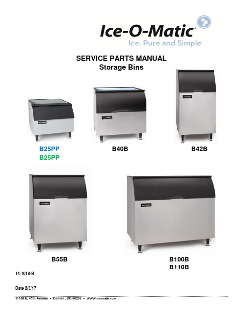
14-1018-B11100 E. 45th Avenue • Denver , CO 80239 • SERVICE PARTS MANUALStorage BinsB42BB40B B100B B55BDate 2/3/17B25PP B25PPB110BStorage Bin Service Parts Table of Contents This parts list contains the service parts available for the Ice-O-Matic storage bins listed below.B25PP From Serial Number 13011320011089 to 15031320014759B25PP From Serial Number 15071280013855B42BB40BB55BB100BB110BCheck the model number on the data plate and refer to the correct listing for the specific component.Check carefully that the correct part is identified and ordered.Table of Contents Page 1 B25PP Page 2 From Serial Number 13011320011089 to 15031320014759B25PP Page 3 From Serial Number 15071280013855B42B Page 4 B40B Page 4 B55B Page 4 B100B Page 4 B110BB42B Page 5 B40B Page 5 B55B Page 5 B100B Page 5 B110BRED=NLA-NR NO LONGER AVAILABLE-NO REPLACEMENTB75Page 6 B70-B90Page 7 B120,B130, B150, B170Page 8 Ice-O-Matic11100 East 45th Ave.Denver Co. 80239From Serial Number 13011320011089 to 1503132001475911011515-01Bin Assembly (Box Only)21011515-02Leg Support31011515-03Door / Shield Assembly (Includes Items 4,15,19,20,21,22,23 and 25)41011515-04Bin Door (Less Gasket see Item 20)53012608-01Bin Connecting Strap61011515-06Skid71011515-07Carton81011515-08Screw #10 x 1/2 PH SS (Stiffner Screws)99031003-10Flat Washer #10109031141-01Plastic Nut111011515-11Screw #10 x 1/2 Truss HD S.S.121011515-12Bolt, 5/8-11 x 1 1/4 (Bin to Skid)139051127-01Bin Scoop141011515-14Leg Set (5/8 x 11 Thread)151011515-15Ice Deflector Drip Sheild161011515-16Drip Shield Gasket (Gasket 1/8 x 1/2 x 30 inches)171011515-17Bin Perimiter Gasket (Gasket 1/4 x 1 x 75.25 inches)189031001-33IOM Logo191011515-19Drip Shield Brace201011515-20Bin Door Gasket (45 Inches Required)219031008-15Door Hinge Screw221011515-22Hinge Bracket Right Hand231011515-23Hinge Bracket Left Hand249031113-03Screw, Bin Connecting Strap251011515-25Drip Shiels Brace ScrewFrom Serial Number 15071280013855Item B25PP Bin Description12031302-01Pivot Bracket-Left Hand 22031302-02Piviot Bracket-Right Hand32031303-97Door, 30 x 11.375 Black Only (Includes Gasket)46081036-01Door Gasket 3.87 Ft. Required 59031008-15P Screw-Pivot Bracket to Door62101252-01Drip Shield/Ice Deflector (Includes item 9)79031098-05P Drip Shield Screw 89031141-01P Plastic Nut93012646-03Drip Shield Stainless Steel Brace109031113-04P Drip Shield Stainless Steel Brace Screws 116081004-07Drip Shield Gasket 2.50 Ft Required 126081004-06Bin Perimeter Gasket 6.42 Ft. Required 133012608-01Connecting Strap149031113-03P Connecting Strap Screw 159021001-04Legs (Set of 4)169051127-01Ice Scoop172031453-01Leg Support (Includes Nut Retainers)189031012-02PLeg Nut RetainerFrom Serial Number 15071280013855Item B42B B40B-B55B B100B/B110Description19051559-039051559-019051559-02Bin Door, Less Bin Door Brackets29051566-039051566-019051566-02Ice Deflector36081004-076081004-076081004-07Gasket B100=4.0 ft B40/55=2.52 ft B42=1.85 ft 46081037-016081037-016081037-01Gasket L Shape B100=7.6 ft B40/55=6.2 ft B42=5.5 ft 53012608-013012608-013012608-01Connecting Strap69031113-04P9031113-04P9031113-04P Connecting Strap Screw79021001-049021001-049021001-04Leg Set (4)89051127-019051127-019051127-01Ice Scoop92031310-03S2031310-03S2031310-03S Leg Support (Includes Nut Retainers)109031012-02P9031012-02P9031012-02P Nut Retainer 1/2-13119051126-019051126-019051126-01Drain Plug129051569-019051569-019051569-01Trim Strip, Right Hand139051569-029051569-029051569-02Trim Strip, Left HandItem B42B B40B-B55B B100B/B110 Description19051559-039051559-019051559-02Bin Door, Less Bin Door Brackets29051566-039051566-019051566-02Ice Deflector39051629-039051629-019051629-02Drip Shield (9051561-01,-02,-03 are NLA)49051567-019051567-019051567-01End Cap Cover5See Notes See Notes 9021110-02Pin, Hinge (Triple)5NLA NLA Pin, Hinge (Double) See Note Below69051560-019051560-019051560-01End Cap, Right79051560-029051560-029051560-02End Cap, Left83013360-013013360-013013360-01Bracket, Bin Door Right93013360-023013360-023013360-02Bracket, Bin Door Left10See Notes See Notes 9021109-02Sleeve, Friction (Triple)10NLA NLA Sleeve, Friction (Dual) See Note Below119131471-029131471-029131471-02Hanger, Ice Scoop (9131471-02 is NLA)129031113-03P9031113-03P9031113-03P Screw, Drip Shield to End Cap (2 per Side)132101452-03S2101452-01S2101452-02S Drip Shield Assembly (Includes Item 3,6,7,10,11 and 12) 149031098-05P9031098-05P9031098-05P Screw, Drip Shield Assembly to Bin Side Panel (2 Per Side) 159031008-15P9031008-15P9031008-15P Screw, Bin Door Hinge (2 per Hinge Required)Note: The Double Ball Hinge Pin and Double Friction Sleeve are No Longer AvailableThe Triple Ball Hinge Pin and Triple Ball Friction Sleeve must be ordered.Storage Bin B75 BinItem B75Description11011369-01Canopy21011369-02Baffle31011369-03Door Assembly41011369-04Drip Molding51011369-05Door Gasket (10 Feet Required)61011369-06Hinge R/H71011369-07Hinge L/H81011369-08Hinge Bushing91011369-09Hinge Spacer101011369-10Shoulder Screw111011369-11E-Clip121011369-12Drain Top131011369-13Legs, Painted (Set of 4)141011369-14Screw - Hinge to Frame151011369-15Screw - Hinge to Door161011369-16Door Hinge L/H171011369-17Door Hinge R/H181011339-104Gasket191011351-69O-Ring201011351-05Drain BottomStorage Bin B70, B90Item B70B90Description11011457-291011457-29Snout Door Catch Bracket 21011457-121011457-12View Window Extrusion Kit 31011457-131011457-13View Window (2 ea.) 41011457-261011457-26Poly Snout Door Hinge Left Hand 51011457-271011457-27Poly Snout Door Hinge Right Hand 61011457-181011457-18Snout Baffle 71011457-141011457-14Poly Snout Extrusion Kit 81011457-201011457-20Poly Snout Door 91011457-221011457-22Poly Snout 101011457-241011457-24Leg (Set of 4) 111011457-251011457-25Plastic Drain 121011457-041011457-04Wall Bracket (2 ea.) 131011457-051011457-05Ice Maker Bracket (2 ea.)1011457-071011457-07B70/90 30 Inch Adapter Top1011457-061011457-06B70/90 1506 Adapter Top1011457-011011457-0148 inch Paddle1011457-021011457-0260 inch Paddle1011457-031011457-03Ice Paddle BracketRED=NLA-NR NO LONGER AVAILABLE-NO REPLACEMENTStorage Bin B120,B130, B150, B170Item B120B130B150B170Description11011457-121011457-121011457-121011457-12View Window Extrusion Kit 21011457-131011457-131011457-131011457-13View Window (2 ea.)31011457-281011457-281011457-281011457-28Snout Assembly (Includes 4,6,7,8,9,10 & 11) 41011457-191011457-191011457-191011457-19Snout Baffle51011457-151011457-151011457-151011457-15Poly Snout Extrusion Kit 61011457-271011457-271011457-271011457-27Poly Snout Door Hinge Right Hand 71011457-261011457-261011457-261011457-26Poly Snout Door HingeLeft Hand 81011457-231011457-231011457-231011457-23Poly Snout91011457-171011457-171011457-171011457-17Spring Loaded Snout Door Hinge Left Hand 101011457-161011457-161011457-161011457-16Spring Loaded Snout Door Hinge Right Hand 111011457-211011457-211011457-211011457-21Poly Snout Door121011457-241011457-241011457-241011457-24Leg (Set of 4)131011457-251011457-251011457-251011457-25Plastic Drain 1011457-011011457-011011457-011011457-0148 inch Paddle1011457-021011457-021011457-021011457-0260 inch Paddle1011457-031011457-031011457-031011457-03Ice Paddle Bracket1011457-081011457-08NA NA48 inch Poly Top NA NA1011457-091011457-0960 inch Poly Top 1011457-101011457-101011457-101011457-109 inch Filler Panel1011457-111011457-111011457-111011457-1113 inch Filler PanelRED=NLA-NR NO LONGER AVAILABLE-NO REPLACEMENT。
- 1、下载文档前请自行甄别文档内容的完整性,平台不提供额外的编辑、内容补充、找答案等附加服务。
- 2、"仅部分预览"的文档,不可在线预览部分如存在完整性等问题,可反馈申请退款(可完整预览的文档不适用该条件!)。
- 3、如文档侵犯您的权益,请联系客服反馈,我们会尽快为您处理(人工客服工作时间:9:00-18:30)。
三、228UTM/253UTM/280UTM:
1.故障代码定义:
故障内容
故障代码
冷藏室温度传感器故障
冷藏室温度显示区闪烁显示“E1”
变温室温度传感器故障
变温室温度显示区闪烁显示“E3”
冷冻室温度传感器故障
冷冻室温度显示区闪烁显示“E2”
通讯故障
冷冻室温度显示区闪烁显示“E6”
冷藏室化霜温度传感器故障
欧款冰箱维修手册(电控部分)
一、220UM冰箱电气原理图:
二、220UEM/276UEM
1.故障代码定义:
故障内容
故障代码
冷藏室温度传感器故障
冷藏室温度显示“E2”
通讯故障
冷冻室温度显示区闪烁显示“E6”
冷藏室化霜温度传感器故障
冷藏室温度显示区闪烁显示“E7”
冷藏室温度显示区闪烁显示“E7”
变温室化霜温度传感器故障
变温室温度显示区闪烁显示“E8”
2、电气原理图:
.228UTM冰箱
.253UTM/283UTM冰箱