人机界面控制器
项目六 人机界面(HMI)的组态与应用

”按钮或者鼠标直接
图6.43 编写程序界面
任务实施操作步骤
五、下载项目
先下载 PLC 项目程序。在项目视图中,选中项目树中的“PLC1(CPU1214C)” 单击工具栏中的下载图标“ ”,打开“扩展的下载到设备”对话框,如图 6.44 所示。此处勾选“显示所有可访问设备”,若已将编程计算机和 PLC 连接好,则 将显示当前网络中所有可访问的设备,选中目标 PLC,单击“下载”按钮,将项 目下载到 S7-1200PLC 中。
6.1.1 人机界面与触摸屏
2.触摸屏 西门子的触摸屏面板(Touch Panel,TP),一般俗称为触摸屏。
触摸屏是人机界面的发展方向,用户可以在触摸屏的屏幕 上生成满足自己要求的触摸式按键。触摸屏使用直观方便, 易于操作。画面上的按钮和指示灯可以取代相应的硬件元 件,减少PLC需要的I/O点数,降低系统的成本,提高设备的 性能和附加价值。
图6.2 创建新项目1
图6.3 创建新项目2
一、系统硬件组态
2、添加硬件设备
①添加PLC控制器。 如图6.3,单击“设备与网络”选项中的“组
态设备”,添加系统相关硬件设备,出现图 6.4所示窗口。单击图6.4窗口中的“添加新设 备”,出现如图6.5“新设备”选择窗口。
图6.4 组态硬件设备及网络窗口
项目六 人机界面(HMI)的组态与应用 任务18 基于触摸屏实现电机启停控制
任务介绍
本项目任务选择西门子SIMATIC HMI精简系列面板KTP700 BASIC PN触摸屏作为人机界面,以S7-1200作为控制器,通 过单击触摸屏上的“启动”和“停止”按钮,实现对电机 的启停控制,并且通过触摸屏上的“系统指示灯”和“电 机状态显示”等对象实现对现场系统工作状态的监控功能。
(安全人机工程学)第6章人机界面设计

控制器设计应便于维护和修理,降低维护成本和时 间。
CHAPTER 04
交互设计
交互方式的类型与选择
文本输入
提供文本输入选项,允许用户通过键盘或手 写输入信息。
语音识别
利用语音识别技术,允许用户通过语音与系 统进行交互。
图形界面
使用图形元素,如按钮、图标和菜单,提供 直观的操作方式。
触摸屏
提供触摸屏界面,使用户能够通过触摸操作 与系统进行交互。
交互界面的设计要素
布局
合理安排界面元素的位置,确 保用户能够快速找到所需功能
。
色彩搭配
选择适当的颜色,以增强界面 的视觉效果和用户体验。
字体选择
使用清晰易读的字体,确保用 户在阅读信息时不会感到疲劳 。
图标与按钮
设计简洁明了的图标和按钮, 以便用户快速识别和操作。
信息可读性
显示信息应清晰、易读,避免产生视觉疲劳和误读。
可视化友好
对于视觉显示,应采用易于理解的图表、符号等可视 化元素,提高信息传达效果。
CHAPTER 03
控制器设计
控制器的类型与选择
1 2 3
机械式控制器
利用机械原理实现控制功能的控制器,如开关、 旋钮等。选择时应考虑其可靠性、耐久性和稳定 性。
提供一定程度的个性化 设置选项,满足不同用 户的习惯和需求。
人机界面设计发展趋势
整合多种交互方式,如语音、手势、 触摸等,提供更加自然和便捷的交互 体验。
将情感因素融入界面设计,增强用户 与界面的情感联系,提升用户体验的 愉悦感和满足感。
智能化
多模态交互
无障碍设计
情感化设计
借助人工智能技术,实现界面的自适 应、智能推荐等功能,提高用户体验。
人机界面百度百科

人机界面百科名片人机界面(又称用户界面或使用者界面)是系统和用户之间进行交互和信息交换的媒介,它实现信息的内部形式与人类可以接受形式之间的转换。
凡参与人机信息交流的领域都存在着人机界面。
编辑本段人机界面概念介绍人机界面(Human–Machine Interaction,简称HMI),是人与计算机之间传递、交换信息的媒介和对话接口,是计算机系统的重要组成部分。
是指人和机器在信息交换和功能上接触或互相影响的领域或称界面所说人机结合面,信息交换,功能接触或互相影响,指人和机器的硬接触和软触,此结合面不仅包括点线面的直接接触,还包括远距离的信息传递与控制的作用空间。
人机结合面是人机系统中的中心一环节,主要由安全工程学的分支学科安全人机工程学去研究和提出解决的依据,并过安全工程设备工程学,安全管理工程学以及安全系统工程学去研究具体的解决方法手段措施安全人机学。
它实现信息的内部形式与人类可以接受形式之间的转换。
凡参与人机信息交流的领域都存在着人机界面。
现在大量运用在工业与商业上,简单的区分为“输入”(Input)与“输出”(Ouput)两种,输入指的是由人来进行机械或设备的操作,如把手、开关、门、指令(命令)的下达或保养维护等,而输出指的是由机械或设备发出来的通知,如故障、警告、操作说明提示等,好的人机接口会帮助使用者更简单、更正确、更迅速的操作机械,也能使机械发挥最大的效能并延长使用寿命,而目前市面上所指的人机接口则多界狭义的指在软件人性化的操作接口上。
特定行业的人机界面可能有特定的定义和分类,比如工业人机界面(Industrial Human-machine Interface 或简称Industrial HMI),具体解释可查看“工业人机界面”词条。
编辑本段人机交互概念介绍人机交互、人机互动(Human-Computer Interface,简写HCI,又称用户界面或使用者界面):是一门研究系统与用户之间的互动关系的学问。
PLC与人机界面(HMI)的集成与应用

PLC与人机界面(HMI)的集成与应用PLC(可编程逻辑控制器)和人机界面(HMI)是现代自动化系统中常见的两个关键组成部分,它们之间的集成与应用对于实现高效的工业控制至关重要。
本文将从几个方面探讨PLC与HMI的集成与应用,并介绍其在工业控制领域的重要性。
一、PLC与HMI简介PLC是一种专门用于控制工业过程和机器的计算机设备。
它通过预先编程的指令,根据输入信号采取相应的控制动作,控制输出信号的状态。
PLC具有可靠性高、可编程性强、扩展性好等特点,被广泛应用于制造业、自动化工程等领域。
HMI是指人与机器之间进行交互的界面,通常由触摸屏和相应的软件组成。
人机界面的主要功能是显示和操作PLC系统的各种信息,包括实时数据、报警信息、设备状态等。
通过直观、友好的界面,操作人员可以方便地控制和监测工业系统的运行状态。
二、PLC与HMI的集成方式1. 直接连接方式最简单的集成方式是将PLC和HMI直接连接在一起。
PLC通过一个特定的通信模块与HMI进行通信,实现数据的传输和控制的交互。
这种方式适用于小型控制系统,但对于大型系统来说,直接连接方式可能导致数据传输速度慢、容错性差等问题。
2. 以太网连接方式采用以太网连接方式可以克服直接连接方式的局限性。
通过以太网通信,PLC和HMI可以实现高速稳定的数据传输。
此外,以太网连接方式还支持远程监控和管理,方便维护人员对系统进行远程操作。
3. 使用总线通信方式使用总线通信方式是集成PLC和HMI的一种常见方式,常见的总线通信协议包括Profibus、Modbus、CAN等。
通过总线通信,PLC和HMI可以实现多路通信,提高系统的扩展性和灵活性。
三、PLC与HMI的应用1. 自动化生产线控制在自动化生产线上,PLC和HMI的集成应用十分广泛。
通过PLC控制器对生产线各个步骤进行编程,再通过HMI界面,操作人员可以实时监测生产状态、设备运行参数,并可以进行相关参数的调整和控制,从而提高生产效率和产品质量。
可编程控制器与人机界面

知识链接三 :昆仑通态触摸屏TPC7062K
注:查找触摸屏TPC7062K的相关资料
• 知识链接四: MCGS嵌入版组态软件
MCGS嵌入版组态软件是昆仑通态公司专 门开发用于mcgsTpc的组态软件。
MCGS嵌入版组态软件与其他相关的硬件 设备结合,可以快速、方便的开发各种 用于现场采集、数据处理和控制的设备。
出安装程序窗口。点击“下一步”,启动安 装程序。
按提示步骤操作,随后,安装程序将提示指定
安装目录,用户不指定时,系统缺省安装到 D:\MCGSE目录下,建议使用缺省目录,如 图所示,系统安装大约需要几分钟;
• MCGS嵌入版主程序安装完成后,继续安 装设备驱动,选择“是”;
• 点击下一步,进入驱动安装程序,选 择所有驱动,点击下一步进行安装;
选择好后,按提示操作,MCGS驱动程序 安装过程大约需要几分钟;
安装过程完成后,系统将弹出对话框提示 安装完成,提示是否重新启动计算机, 选择重启后,完成安装。
安装完成后,Windows操作系统的桌面上 添加了如下图所示的两个快捷方式图标, 分别用于启动MCGS嵌入式组态环境和 模拟运行环境:Leabharlann (2)连接TPC7062K和PC机
如可以灵活组态各种智能仪表、数据采集 模块,无纸记录仪、无人值守的现场采 集站、人机界面等专用设备。
1、MCGS嵌入版组态软件的主要功能 (1)简单灵活的可视化操作界面 (2)实时性强、有良好的并行处理性能 (3)丰富、生动的多媒体画面 (4)完善的安全机制 (5)强大的网络功能 (6)多样化的报警功能 (7)支持多种硬件设备 特点:MCGS嵌入版组态软件具有与通用
• 知识链接二 : 触摸屏
触控屏(Touch panel)又称为触控面板 起源于20世纪70年代,目 前触摸屏的应用范围从工 业用途的工厂设备的控制 /操作系统、公共信息查询 的电子查询设施、商业用 途的银行自动柜员机、工 控机等,迅速扩展到手机、 PDA、GPS、PMP(MP3, MP4等),甚至平板电脑 (Tablet PC)等大众消 费电子领域。
可编程逻辑控制器与人机界面
Programmable Logic Controller And Human Machine InterfaceAlong with the development of the ages, the technique that is nowadays is also gradually perfect, the competition plays more strong; the operation that list depends the artificial has already can't satisfied with the current manufacturing industry foreground, also can't guarantee the request of the higher quantity and high new the image of the technique business enterprise.The people see in produce practice, automate brought the tremendous convenience and the product quantities for people up of assurance, also eased the personnel's labor strength, reduce the establishment on the personnel. The target control of the hard realization in many complicated production lines, whole and excellent turn, the best decision etc., well-trained operation work, technical personnel or expert, governor but can judge and operate easily, can acquire the satisfied result. The research target of the artificial intelligence makes use of the calculator exactly to carry out, imitate these intelligences behavior, moderating the work through person's brain and calculators, with the mode that person's machine combine, for resolve the very complicated problem to look for the best path.We come in sight of the control that links after the electric appliances in various situation, that is already the that time generation past, now of after use in the mold a perhaps simple equipments of grass-roots control that the electric appliances can do for the low level only; And the PLC emergence also became the epoch-making topic, adding the vivid software control through a very and stable hardware, making the automation head for the new high tide.The PLC was invented in response to the needs of the American automotive manufacturing industry. Programmable logic controllers were initially adopted by the automotive industry where software revision replaced the re-wiring of hard-wired control panels when production models changed.Before the PLC, control, sequencing, and safety interlock logic for manufacturing automobiles was accomplished using hundreds or thousands of relays, cam timers, and drum sequencers and dedicated closed-loop controllers. The process for updating such facilities for the yearly model change-over was very time consuming and expensive, as electricians needed to individually rewire each and every relay.In 1968 GM Hydramatic (the automatic transmission division of General Motors) issued a request for proposal for an electronic replacement for hard-wired relay systems. The winning proposal came from Bedford Associates of Bedford, Massachusetts. The first PLC, designated the 084 because it was Bedford Associates' eighty-fourth project, was the result. Bedford Associates started a new company dedicated to developing, manufacturing, selling, and servicing this new product: Modicon, which stood for MOdular DIgital CONtroller. One of the people who worked on that project was Dick Morley, who is considered to be the "father" of the PLC. The Modicon brand was sold in 1977 to Gould Electronics, and later acquired by German Company AEG and then by French Schneider Electric, the current owner.One of the very first 084 models built is now on display at Modicon's headquarters in North Andover, Massachusetts. It was presented to Modicon by GM, when the unit was retired after nearly twenty years of uninterrupted service. Modicon used the 84 moniker at the end of its product range until the 984 made its appearance.The automotive industry is still one of the largest users of PLCs.Early PLCs were designed to replace relay logic systems. These PLCs were programmed in "ladder logic", which strongly resembles a schematic diagram of relay logic. This program notation was chosen to reduce training demands for the existing technicians. Other early PLCs used a form of instruction list programming, based on a stack-based logic solver.Modern PLCs can be programmed in a variety of ways, from ladder logic to more traditional programming languages such as BASIC and C. Another method is State Logic, a very high-level programming language designed to program PLCs based on state transition diagrams.Many early PLCs did not have accompanying programming terminals that were capable of graphical representation of the logic, and so the logic was instead represented as a series of logic expressions in some version of Boolean format, similar to Boolean algebra. As programming terminals evolved, it became more common for ladder logic to be used, for the aforementioned reasons. Newer formats such as State Logic and Function Block (which is similar to the way logic is depicted when using digital integrated logic circuits) exist, but they are still not as popular as ladder logic.A primary reason for this is that PLCs solve the logic in a predictable and repeating sequence, and ladder logic allows the programmer (the person writing the logic) to see any issues with the timing of the logic sequence more easily than would be possible inother formats.2.1ProgrammingEarly PLCs, up to the mid-1980s, were programmed using proprietary programming panels or special-purpose programming terminals, which often had dedicated function keys representing the various logical elements of PLC programs. Programs were stored on cassette tape cartridges. Facilities for printing and documentation were very minimal due to lack of memory capacity. The very oldest PLCs used non-volatile magnetic core memory.More recently, PLCs are programmed using application software on personal computers. The computer is connected to the PLC through Ethernet, RS-232, RS-485 or RS-422 cabling. The programming software allows entry and editing of the ladder-style logic. Generally the software provides functions for debugging and troubleshooting the PLC software, for example, by highlighting portions of the logic to show current status during operation or via simulation. The software will upload and download the PLC program, for backup and restoration purposes. In some models of programmable controller, the program is transferred from a personal computer to the PLC though a programming board which writes the program into a removable chip such as an EEPROM or EPROM.The functionality of the PLC has evolved over the years to include sequential relay control, motion control, process control, distributed control systems and networking. The data handling, storage, processing power and communication capabilities of some modern PLCs are approximately equivalent to desktop computers. PLC-like programming combined with remote I/O hardware, allow a general-purpose desktop computer to overlap some PLCs in certain applications. Regarding the practicality of these desktop computer based logic controllers, it is important to note that they have not been generally accepted in heavy industry because the desktop computers run on less stable operating systems than do PLCs, and because the desktop computer hardware is typically not designed to the same levels of tolerance to temperature, humidity, vibration, and longevity as the processors used in PLCs. In addition to the hardware limitations of desktop based logic, operating systems such as Windows do not lend themselves to deterministic logic execution, with the result that the logic may not always respond to changes in logic state or input status with the extreme consistency in timing as is expected from PLCs. Still, such desktop logic applications find use in less critical situations, such as laboratory automation and usein small facilities where the application is less demanding and critical, because they are generally much less expensive than PLCs.In more recent years, small products called PLRs (programmable logic relays), and also by similar names, have become more common and accepted. These are very much like PLCs, and are used in light industry where only a few points of I/O (i.e. a few signals coming in from the real world and a few going out) are involved, and low cost is desired. These small devices are typically made in a common physical size and shape by several manufacturers, and branded by the makers of larger PLCs to fill out their low end product range. Popular names include PICO Controller, NANO PLC, and other names implying very small controllers. Most of these have between 8 and 12 digital inputs, 4 and 8 digital outputs, and up to 2 analog inputs. Size is usually about 4" wide, 3" high, and 3" deep. Most such devices include a tiny postage stamp sized LCD screen for viewing simplified ladder logic (only a very small portion of the program being visible at a given time) and status of I/O points, and typically these screens are accompanied by a 4-way rocker push-button plus four more separate push-buttons, similar to the key buttons on a VCR remote control, and used to navigate and edit the logic. Most have a small plug for connecting via RS-232 or RS-485 to a personal computer so that programmers can use simple Windows applications for programming instead of being forced to use the tiny LCD and push-button set for this purpose. Unlike regular PLCs that are usually modular and greatly expandable, the PLRs are usually not modular or expandable, but their price can be two orders of magnitude less than a PLC and they still offer robust design and deterministic execution of the logic.The main difference from other computers is that PLCs are armored for severe conditions (such as dust, moisture, heat, cold) and have the facility for extensive input/output (I/O) arrangements. These connect the PLC to sensors and actuators. PLCs read limit switches, analog process variables (such as temperature and pressure), and the positions of complex positioning systems. Some use machine vision. On the actuator side, PLCs operate electric motors, pneumatic or hydraulic cylinders, magnetic relays, solenoids, or analog outputs. The input/output arrangements may be built into a simple PLC, or the PLC may have external I/O modules attached to a computer network that plugs into the PLC.A small PLC will have a fixed number of connections built in for inputs and outputs. Typically, expansions are available if the base model has insufficient I/O.Modular PLCs have a chassis (also called a rack) into which are placed modules with different functions. The processor and selection of I/O modules is customised for the particular application. Several racks can be administered by a single processor, and may have thousands of inputs and outputs. A special high speed serial I/O link is used so that racks can be distributed away from the processor, reducing the wiring costs for large plants.PLCs may need to interact with people for the purpose of configuration, alarm reporting or everyday control.A simple system may use buttons and lights to interact with the user. Text displays are available as well as graphical touch screens. More complex systems use a programming and monitoring software installed on a computer, with the PLC connected via a communication interface.PLCs have built in communications ports, usually 9-pin RS-232, but optionally EIA-485 or Ethernet. Modbus, BACnet or DF1 is usually included as one of the communications protocols. Other options include various fieldbuses such as DeviceNet or Profibus. Other communications protocols that may be used are listed in the List of automation protocols.Most modern PLCs can communicate over a network to some other system, such as a computer running a SCADA (Supervisory Control And Data Acquisition) system or web browser.PLCs used in larger I/O systems may have peer-to-peer (P2P) communication between processors. This allows separate parts of a complex process to have individual control while allowing the subsystems to co-ordinate over the communication link. These communication links are also often used for HMI devices such as keypads or PC-type workstations.PLC programs are typically written in a special application on a personal computer, then downloaded by a direct-connection cable or over a network to the PLC. The program is stored in the PLC either in battery-backed-up RAM or some other non-volatile flash memory. Often, a single PLC can be programmed to replace thousands of relays.Under the IEC 61131-3 standard, PLCs can be programmed using standards-based programming languages. A graphical programming notation called Sequential Function Charts is available on certain programmable controllers. Initially most PLCs utilized Ladder Logic Diagram Programming, a model which emulatedelectromechanical control panel devices (such as the contact and coils of relays) which PLCs replaced. This model remains common today.IEC 61131-3 currently defines five programming languages for programmable control systems: FBD (Function block diagram), LD (Ladder diagram), ST (Structured text, similar to the Pascal programming language), IL (Instruction list, similar to assembly language) and SFC (Sequential function chart). These techniques emphasize logical organization of operations.While the fundamental concepts of PLC programming are common to all manufacturers, differences in I/O addressing, memory organization and instruction sets mean that PLC programs are never perfectly interchangeable between different makers. Even within the same product line of a single manufacturer, different models may not be directly compatible.Human Machine Interface (HMI) combines with the Programmable Logic Controller to our larger space.Good interface design is very important, because compared with other characteristics, the system to give users leave system interface more deep impression. After all, users from will often system usability perspective on a system, not from how it ingeniously carried out its internal task this Angle. From the user's perspective they may according to system interface in a competition to choose between sexual system. Therefore, the system interface design can be convicted a software project success final decision factors.For these reasons, man-machine interface in a software development project needs the analysis phase has become a very important concerns for software engineering, and it a branch area. In fact, some people claim that the man-machine interface research is a completely independent field.The current status of HMI (Human Machine Interface) in the field of industrial automation is characterized by a predominance of embedded lowpower devices that are interfaced with proprietary or standard field buses specifically devised for the industrial plant monitoring and automation.Commercial systems typically rely on proprietary architectures for the hardware and the operating systems, the I/O interface, the communication protocols implementation, the graphic display management, and the business logics. This situation is largely due to the strong focus on costs, performances and reliability, which overcomes the interest in standard architectures and high quality of interfacesand services. Moreover, industrial automation communication protocols have not reached the same level of standardization as office communication networks, which further justifies the predominance of proprietary architectures.However, the success of the Internet and of the Web has started impacting the industrial HMI world too. Industrial users are starting to familiarize with Web interfaces, graphical quality, multimedia content, and features such as mobility, adaptivity, and personalization of the applications. At the same time,TCP-IP based communication protocols and embedded operating systems have started to spread in the industrial automation field [6][10], thus reducing the need of proprietary architectures making enterprisewide integration more appealing. In this scenario, it is easy to foresee a slow but inexorable convergence of the industrial HMI solutions towards standard architectures, standard communication protocols, and advanced interactive functions.HMI the control not only is reduced the control press button, increase the vivid of the control, more main of it is can sequence of, and at can the change data input to output the feedback with data, control in the temperature curve of imitate but also can keep the manifestation of view to come out. And can write the function help procedure through a plait to provide the help of various what lies in one's power, the one who make operate reduces the otiose error. Currently the HMI factory is also more and more, the function is also more and more strong, the price is also more and more low, and the noodles of the usage are wide more and more. The HMI foreground can say that think to be good very.可编程逻辑控制器与人机界面随着时代的发展,当今的技术也日趋完善、竞争愈演愈烈,单靠人工的操作已不能满足于目前的制造业前景,也无法保证更高质量的要求和高新技术企业的形象。
人机界面设计的知识结构图

减小手指的重复劳动
音响及报警装置 言语显示装置
听觉显示 器设计
显示器设计
触觉显示 器设计
控制—显示组合设计
控制--显示的空间相合性 控制--显示的运动相合性
受力
累积损伤疾病 及其原因
重复 姿势 休息
累积损伤疾病与 工具设计
与手有关的累 积损伤疾病
避免静肌负荷
手握式工具 设计原则
保持手腕伸直 使组织压迫最小
人机界面设计
人机界面概述
控制器的分类
计要求
控制器的外形结构 控制器的阻力
控制器的偶发启动
手动控制器的设计(旋钮、按 钮、扳动开关、控制板)
主要控制器 的设计
脚动控制器的设计 (脚踏板、脚踏钮)
控制--显示比
信号灯显示设计 仪表显示器
标志符号的设计 荧光屏显示设计
视觉显示 器设计
JMDM-2011 多功能人机界面工业控制器一体机说明书
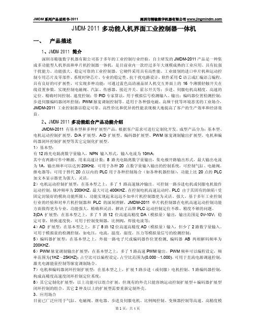
JMDM-2011多功能人机界面工业控制器一体机一、产品描述1、JMDM-2011 简介深圳市精敏数字机器有限公司基于多年的工业控制行业经验,自主研发的JMDM-2011产品是一种集成多功能型人机界面和单片机控制器一体机,是目前业内一款经过多年大规模成熟的工业应用、具有抗强干扰能力、功能强大、稳定可靠的工业控制器。
它硬件采用具有高性能、工业级别的进口单片机和运动控制专用芯片及零部件、系统时钟芯片,专业的稳定性、抗干扰电路设计,软件采用C语言或汇编语言编程,具有良好的可扩展性,可实现多种功能:可通过蓝色高清液晶屏人机交互界面上的16个薄膜轻触开关在线设置参数,实现控制电磁阀、汽缸、传感器、接近开关、霍尔开关等;步进、伺服电机高精度、高速的定位、精确时间控制、速度控制;带PID专家算法,用于模拟信号检测输入、输出;编码器位置检测控制;步进伺服编码器闭环控制;PWM脉宽调制控制等。
适用于各种强电磁、高频干扰等环境恶劣的工业场合,JMDM-2011工业控制器以稳定可靠、高性价比和优异的性能表现极大地提高了客户的生产效率和经济效益。
2、JMDM-2011多功能组合产品功能介绍JMDM-2011 有基本型和多种扩展型产品,根据客户需求可进行定制化开发。
成型产品分为:基本型、电机运动控制扩展型、D/A扩展型、A/D扩展型、编码器扩展型、PWM脉宽调制输出扩展型、电机和编码器闭环控制扩展型等其它定制化扩展型。
1)基本型:有12路光电隔离数字量输入,NPN 输入形式,输入电流为10mA;其中有两路可作中断源,用来高速计数;8 路光电隔离数字量输出,集电极开路输出形式,最大输出电流为1A,输出频率可以达到20KHz。
可用于各种20 点数字量输入输出的控制系统,可控制气缸、电磁阀、继电器等;可用于替代20点以内的PLC用于各种控制场合(如各种机器控制),功能上比20点的PLC 加文本显示器更为强大、灵活。
2)电机运动控制扩展型:在基本型之上,多了1 路高速脉冲输出。
人机界面(HMI)产品常识
人机界面(HMI)产品常识一、人机界面(HMI)产品常识1、人机界面产品的定义连接可编程序控制器(PLC)、变频器、直流调速器、仪表等工业控制设备,利用显示屏显示,通过输入单元(如触摸屏、键盘、鼠标等)写入工作参数或输入操作命令,实现人与机器信息交互的数字设备,由硬件和软件两部分组成。
2、人机界面(HMI)产品的组成及工作原理人机界面产品由硬件和软件两部分组成,硬件部分包括处理器、显示单元、输入单元、通讯接口、数据存贮单元等,其中处理器的性能决定了HMI产品的性能高低,是HMI的核心单元。
根据HMI的产品等级不同,处理器可分别选用8位、16位、32位的处理器。
HMI 软件一般分为两部分,即运行于HMI硬件中的系统软件和运行于PC机Windows操作系统下的画面组态软件(如JB-HMI画面组态软件)。
使用者都必须先使用HMI的画面组态软件制作“工程文件”,再通过PC机和HMI 产品的串行通讯口,把编制好的“工程文件”下载到HMI的处理器中运行。
3、人机界面产品的基本功能及选型指标基本功能:设备工作状态显示,如指示灯、按钮、文字、图形、曲线等数据、文字输入操作,打印输出生产配方存储,设备生产数据记录简单的逻辑和数值运算可连接多种工业控制设备组网选型指标:显示屏尺寸及色彩,分辨率HMI的处理器速度性能输入方式:触摸屏或薄膜键盘画面存贮容量,注意厂商标注的容量单位是字节(byte)、还是位(bit)通讯口种类及数量,是否支持打印功能4、人机界面产品分类薄膜键输入的HMI,显示尺寸小于5.7ˊ,画面组态软件免费,属初级产品。
如POP-HMI 小型人机界面触摸屏输入的HMI,显示屏尺寸为5.7ˊ~12.1ˊ,画面组态软件免费,属中级产品基于平板PC计算机的、多种通讯口的、高性能HMI,显示尺寸大于10.4ˊ,画面组态软件收费,属高端产品5、人机界面的使用方法明确监控任务要求,选择适合的HMI产品在PC机上用画面组态软件编辑“工程文件”测试并保存已编辑好的“工程文件”PC机连接HMI硬件,下载“工程文件”到HMI中连接HMI和工业控制器(如PLC、仪表等),实现人机交互。
伺服控制器在人机界面中的应用
伺服控制器在人机界面中的应用人机界面(HMI)是指人与机器之间进行交互的界面,它通过图形化显示和操作方式将人员的意图传达给机器,从而控制机器的运行状态。
伺服控制器作为一种专门用于控制伺服电机的设备,也需要在人机界面中进行应用。
本文将探讨伺服控制器在人机界面中的应用,包括其原理、优势以及可能遇到的挑战。
首先,让我们了解一下伺服控制器的原理。
伺服控制器是一种实时控制器,用于控制伺服电机的位置、速度和加速度等运动参数。
它通过接收来自传感器的反馈信号,并根据设定的目标值计算输出信号来实现对伺服电机的控制。
在人机界面中的应用中,伺服控制器必须与人机界面软件进行通信,接收人员输入的指令,并将控制信号传输给伺服电机,从而实现对运动系统的精确控制。
在人机界面中应用伺服控制器有许多优势。
首先,伺服控制器能够实现对伺服电机的高精度控制。
它可以根据设定的目标值和反馈信号实时调整输出信号,从而实现位置、速度和加速度的精确控制。
这使得伺服控制器特别适用于要求精准定位和快速响应的应用,例如机床加工、自动化生产线等。
其次,伺服控制器具有简单易用的人机界面。
人机界面软件通常提供了直观的图形化界面,使得操作员可以轻松地设置运动参数、监控运动状态以及做出相应的调整。
这简化了操作流程,提高了工作效率,并降低了人员操作的难度。
另外,伺服控制器还具有良好的稳定性和可靠性。
它能够快速响应输入信号,并根据设定的控制算法进行运动控制,从而保证了运动系统的稳定性。
同时,伺服控制器还具备故障检测和诊断功能,能够实时监测运动状态并提供相应的故障信息,帮助操作员快速识别和解决问题。
然而,在将伺服控制器应用于人机界面中时,也可能面临一些挑战。
首先,伺服控制器的配置和调试可能较为复杂。
由于伺服控制器需要和人机界面软件进行通信,需要设置相应的通信接口和协议。
在配置和调试过程中,可能需要花费一定的时间和精力来确保系统正常运行。
其次,由于伺服控制器涉及到对运动系统的控制,必须要有必要的专业知识和技能。
第六章 人机界面设计 2
3. 控制器要利于辨认和记忆。 当控制器较多时,要从外形、大小和颜色上区别,并尽 量与其功能有逻辑上的联系,这样可以便于操作者辨认。 4. 尽量利用控制器的结构特点进行控制(如弹簧、点动开关 等)或借助操作者体位的重力进行控制(如脚踏开关) ,以 防疲劳和产生单调感。 5. 尽量设计多功能控制器。 例如:车床进给箱上的手柄。 三、控制器设计的工效学设计原则 主要讨论设计控制器时如何考虑人机关系的因素,如控 制器的形状、大小、位臵、操纵力、运动方向、运动范围和 环境条件与系统反应的关系等。 1.控制器编码 将控制器进行合理编码,便于操作者辨认和记忆,可以 有效减少误操作。
(2)按操作顺序排列 多个控制器,如有较固定的操作顺序,应依照操作顺序 排列控制器,排列的方向宜与肢体活动的自然习惯方向一致:
横向排列时按从左到右的顺序, 竖向排列时按从上到下的顺序, 环状排列时按顺时针的顺序。 3. 避免误操作与操作干扰 (1)各控制器间保持足够距离。 为避免互相干扰,避免操作中连带误触动作,同一平面 上相邻布臵的控制器间应保持足够的距离。 对于引起工作状态翻转或清零的控制器,不宜安排在操 作重复程度高的动作轨迹上,以免传授严重的无意误操作。
(6)标记编码 在不同控制器的上方或旁边,标注不同的文字或符号, 通过这些文字或符号标示控制器的使用功能。 例如:计算机显示器的亮度、色彩、对比度等的调节旋 钮以及一些消费电子产品上的表示运转速度的箭头标志等。 例如:录音机上按键。超级解霸软件界面。 它是一种简单而又应用很普遍的编码方式,采用这种编 码方式,需要有良好的照明条件,同时还需要占有一定的控 制面板空间。 注意: ①标记要简明、通用,尽可能不使用抽象符号; ②标记应清晰、可读; ③标记位臵应有规则性,并在操纵时标记在视野范围内, 尽量把标记放在控制器上方; ④应有良好的周围照明条件,也可使用局部照明或者采 用自发光标记。
SZ7G SZ7GE SZ7GS SZ7GES 系列人机界面说明书
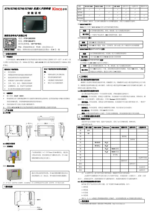
dingh1.1环境要求工作环境温度:SZ7G/SZ7GE 系列人机界面的设计规范可以保证它能够在32℉~122℉(0~50℃)的大多数工业环境中稳定工作。
NEMA 防护规定:SZ7G/SZ7GE 系列人机界面的前面板符合NEMA1的防护规定。
1.2电源要求 输入电压:DC16V~DC32V;特别需要注意与变频调速器和开关电源供应器保持较远的距离,这类设备的输入和输出电缆都必须采用屏蔽电缆,并将屏蔽网接到系统的星形接地点;直流电源必须与交流主电源正确的隔离开;不要让SZ7G/SZ7GE 系列人机界面和感性负载或控制器的输入电路共用电源。
2.1尺寸图2.2安装方式说明2.2.1支架固定2.2.2悬挂式安装注:本产品出厂仅提供M4安装螺钉,见包装纸盒,如上支架和钣金挂件为示意图,仅供参考,用户需自行定制。
功能RS485(COM0)RS232(COM2)以太网口USB HOST 急停开关三选择开关握持开关SZ7G √√√√√SZ7GE √√√√SZ7GS √√√√√√SZ7GES√√√√√注:1.RS485、RS232、以太网口都集成在14芯屏蔽电缆内,详见下文线缆信号说明。
3.1RS232(COM2)串口RS232串口可用于SZ7G/SZ7GS 系列人机界面的编程和调试。
3.2USB HOST 接口3.3RS485(COM0)串口(SZ7G/SZ7GS 支持)3.4以太网接口(SZ7GE/SZ7GES 支持)以太网接口为10M/100M 自适应以太网端口。
连接14芯屏蔽电缆的灰、红、黑、黄色线(见下文线缆具体说明)端口作用用于HMI 组态的上/下载,系统参数的设置和在线模拟;构成多HMI 联机;与PLC 等通过以太网通讯;通过以太网口与PC 机通讯4.1进入模式选择界面操作说明触摸屏上电前用手指按住液晶屏不放,给触摸屏上电,待触摸屏自动进入模式选择界面之后方可松手,根据模式选择界面提示进入相关操作。
《电气控制与PLC》项目6人机界面及组态软件

任务6.1 人机界面
人机界面(HumanMachine Interaction,简称 HMI),是人与计算机之间传递、交换信息的媒 介和对话接口,是计算机系统的重要组成部分。 是指人和机器在信息交换和功能上接触或互相影 响的领域或称界面所说的人机结合面,信息交换 ,功能接触或互相影响,指人和机器的硬接触和 软触,此结合面不仅包括点线面的直接接触,还 包括远距离的信息传递与控制的作用空间。
任务6.1.7主要产品品牌分类
1、Proface(普洛菲斯) 2、HITECH(海泰克) 3、BEIJER(北尔) 4、威纶(中国大陆使用的商标) 5、三菱 6、西门子 7、施耐德 8、台达(中达电通股份有限公司) 9、eView(深圳市步科电气有限公司/上海步科自动化有限公司) 10、昆仑通态(北京昆仑通态自动化软件科技有限公司) 11、福州维控 12、深圳显控
任务6.2.4 WinCC flexible 的安 装和基本操作
(一)变量的类型
在WinCC flexible中用到两种类型的变量:
外部变量和内部变量。
1、外部变量 外部变量是HMI设备和PLC进行数据交换的媒介。
2、内部变量 内部变量存贮在HMI设备的内存中,不能够直接与PLC通信。
任务6.2.4 WinCC flexI)产 品相关知识
2、 人机界面(HMI)产品的组成
任务6.1.4人机界面(HMI)产 品相关知识
3、人机界面产品的基本功能及选型指标 4、人机界面产品分类 5、人机界面的使用方法
任务6.1.5人机界主要应用
1、磁卡 2、交通指挥灯 3、遥控器 4、鼠标/图形用户界面 5、条形码扫描器
任务6.2.4 WinCC flexible 的安 装和基本操作
HORNER OCS产品介绍

与您分享美国工业自动化最新产品---“一体化”OCS控制器集PLC,人机界面,I/O和通讯于一体,高性能,低成本,易操作画面编辑与逻辑程序用一套编程软件即可完成,软件免费O perator C ontrol S tations您是否在PLC的应用过程中遇到过这样的问题:I/O设备,PLC,显示设备以及网络分别来自于不同的厂家,我们要花许多时间,经费将他们集成到一起,而且可能还需要购买好几种软件包,很多培训才能完成。
这些无疑增加了我们工作的复杂程度,减缓了产品的研发投放速度,提高了产品的成本从而降低了企业的竞争力。
那么有什么办法可以解决这些问题呢?美国HORNER公司的OCS---一体化可编程人机界面控制器,便可轻松解决这些问题。
它将人机界面,PLC控制器,I/O及通讯集为一体,上下位机使用一套免费的软件编程,无需太多培训便可轻松掌握。
这是一个完美的工业应用“一体化”控制解决方案,为您节省了时间,经费和人力,大大提高了企业的竞争力和盈利能力。
公司介绍:Horner APG是美国Horner Electric Inc.的子公司。
Horner Electric Inc. 始建于1949,总部位于美国印地安纳波利斯。
总公司分为HornerAdvanced Products Group (APG) 和Industrial Sales and Service Group (ISS) 两个子公司。
Horner APG 专门致力于全球自动化控制产品的研发,在全球多个国家地区都设有分支机构,是美国GE 的重要合作伙伴,OEM 制造商。
主要从事原始设备制造(OEMs),涉及行业广泛。
产品主要包括可编程人机界面控制器(OCS);传送带控制器;及为GE Fanuc 制造多种可编程控制器(PLC)模块和操作员工作站,运动控制产品和驱动器。
Horner 公司提出的一体化控制理念,由于其操作简单,灵活,价格便宜越来越为业内人士所接受,正逐渐成为自动化控制行业的主流产品。
可编程控制器原理及应用第5章HMI人机界面技术-文档资料

按钮的属性设置 :点击一下按钮,选中常规属性设置后, 弹出的画面如图5.20所示。在常规中可对按钮的显示模式 进行更改,这里将OFF状态文本修改为“起动” 。
按钮的事件设置:选择“事 件”>>点击“按下”,在右侧 添加函数的下拉菜单中选择 SetBitWhileKeyPressed,见 图5.21。
图5.20按钮常规属性设置界面
图5.21 选择按下-函数-SetBitWhileKeyPressed下拉菜单
双击函数、弹出函数列表界面,如图5.22所示。
图5.22 函数列表
双击右侧的<无值>处,弹出相关的变量选择表,选择相 应的变量双击即可,设置完成后的函数列表如图5.23所示。
图5.23 设置完成的函数列表
图5.13 连接设置选项
先把网络中的配置文选项改为PPI,然后再 把波特率改为9600,其余的参数保持不变,见 图5.15。
图5.14 连接设置PPI通讯选择
图5.15 连接设置波特率选择
② 变量设置 把项目所需要的变量全部加以定义,本项目所需的变量有 输入 2个(起动按钮、停止按钮),输出 1个(电动机)。注 意触摸屏的内部控制输入要用M寄存器。 在屏幕左方项目指令树的通讯下方双击“变量”。再在弹 出的变量设置表内双击 “名称”下方的空白方框,弹出变量1 等一行内容,如图5.16所示。
②电动机运行指示设置 在组态屏幕右侧工具—简单对象工具箱中选个圆,然后进 行常规和事件设置。 电动机动画外观设置:选择圆_1“动画”的“外观”,在 圆_1外观表中的 “启用”□内打√ ,激活变量函数。点击变 量右侧的箭头,选择变量。在类型选择“位” □内打√ ,双 击右侧区域 “值”下方的空白处,在外观表中弹出值、前景 色、背景色和闪烁,并有下拉按钮供选择。
自动化控制器和人机界面系统说明书
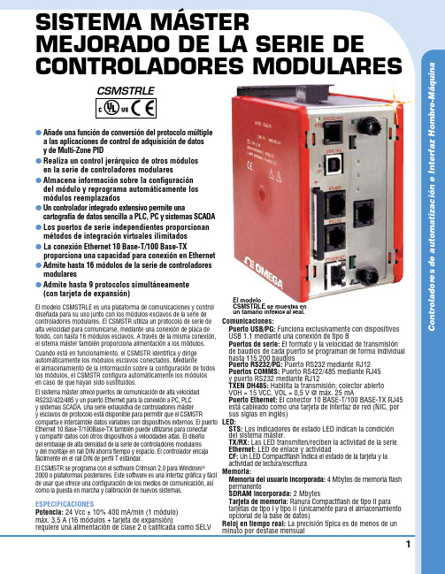
C o n t r o l a d o r e s d e a u t o m a t i z a c i ón e I n t e r f a z H o m b r e -M áq u i n a1SISTEMA MÁSTERMEJORADO DE LA SERIE DE CONTROLADORES MODULARESl A ñade una función de conversión del protocolo múltiple a las aplicaciones de control de adquisición de datos y de Multi-Zone PID l R ealiza un control jerárquico de otros módulos en la serie de controladores modulares l A lmacena información sobre la configuración del módulo y reprograma automáticamente los módulos reemplazados l U n controlador integrado extensivo permite unacartografía de datos sencilla a PLC, PC y sistemas SCADA l L os puertos de serie independientes proporcionan métodos de integración virtuales ilimitados l L a conexión Ethernet 10 Base-T/100 Base-TXproporciona una capacidad para conexión en Ethernet l A dmite hasta 16 módulos de la serie de controladores modulares l A dmite hasta 9 protocolos simultáneamente (con tarjeta de expansión)El modelo CSMSTRLE es una plataforma de comunicaciones y control diseñada para su uso junto con los módulos esclavos de la serie de controladores modulares. El CSMSTR utiliza un protocolo de serie de alta velocidad para comunicarse, mediante una conexión de placa de fondo, con hasta 16 módulos esclavos. A través de la misma conexión, el sitema máster también proporciona alimentación a los módulos. Cuando está en funcionamiento, el CSMSTR identifica y dirige automáticamente los módulos esclavos conectados. Medianteel almacenamiento de la información sobre la configuración de todos los módulos, el CSMSTR configura automáticamente los módulos en caso de que hayan sido sustituidos.El sistema máster ofrece puertos de comunicación de alta velocidad RS232/422/485 y un puerto Ethernet para la conexión a PC, PLC y sistemas SCADA. Una serie exhaustiva de controladores máster y esclavos de protocolo está disponible para permitir que el CSMSTRcomparta e intercambie datos variables con dispositivos externos. El puerto Ethernet 10 Base-T/100Base-TX también puede utilizarse para conectar y compartir datos con otros dispositivos a velocidades altas. El diseño del embalaje de alta densidad de la serie de controladores modulares y del montaje en rail DIN ahorra tiempo y espacio. El controlador encaja fácilmente en el rail DIN de perfil T estándar.El CSMSTR se programa con el software Crimson 2.0 para Windows ® 2000 o plataformas posteriores. Este software es una interfaz gráfica y fácil de usar que ofrece una configuración de los medios de comunicación, así como la puesta en marcha y calibración de nuevos sistemas.ESPECIFICACIONESPotencia: 24 Vcc ± 10% 400 mA/min (1 módulo)máx. 3,5 A (16 módulos + tarjeta de expansión)requiere una alimentación de clase 2 o calificada como SELVComunicaciones:P uerto USB/P G: Funciona exclusivamente con dispositivos USB 1.1 mediante una conexión de tipo B P uertos de serie: El formato y la velocidad de transmisión de baudios de cada puerto se programan de forma individual hasta 115.200 baudiosPuerto RS232/PG: Puerto RS232 mediante RJ12 Puertos COMMS: Puerto RS422/485 mediante RJ45 y puerto RS232 mediante RJ12TXEN DH485: Habilita la transmisión; colector abierto VOH = 15 VCC, VOL = 0,5 V @ máx. 25 mAPuerto Ethernet: El conector 10 BASE-T/100 BASE-TX RJ45 está cableado como una tarjeta de interfaz de red (NIC, por sus siglas en inglés)LED:STS: Los indicadores de estado LED indican la condición del sistema máster.TX/RX: Las LED transmiten/reciben la actividad de la serie Ethernet: LED de enlace y actividad C F: Un LED Compactflash indica el estado de la tarjeta y la actividad de lectura/escritura Memoria: M emoria del usuario incorporada: 4 Mbytes de memoria flash permanenteSDRAM incorporada: 2 Mbytes T arjeta de memoria: Ranura Compactflash de tipo II para tarjetas de tipo I y tipo II (únicamente para el almacenamiento opcional de la base de datos)Reloj en tiempo real: La precisión típica es de menos de un minuto por desfase mensualEl modeloCSMSTRLE se muestra en un tamaño inferior al real.csmstrle2Los controladores vienen completos de serie con conector de terminación, bloque de alimentación terminal, batería de litio y manual del operador.Ejemplo de pedido: CSMSTRLE, controlador, G3CF002G, tarjeta flash de 2 GB, CSDIO14R, módulo de salida con 6 relés de 8 entradas, PSDR0100, alimentación.*Notas:1. Criterio A: funcionamiento normal dentro de ciertos límites.2. Este dispositivo ha sido diseñado para su instalación en un recinto. Para evitar una descarga electrostática de la unidad en entornos con niveles estáticos por encima de 4 kV , se deberán tomar precauciones cuando el dispositivo se monte fuera del recinto. Cuando se trabaja en un recinto (p. ej. realizando ajustes, configuración de puentes, etc.), se deberán tomar precauciones relativas a las descargas de electricidad estática antes de manipular la unidad.Batería: Pila botón litio (incluida). Vida útil normal de 10 años a 25 °C (77 °F)Condiciones ambientales: R ango de temperatura de funcionamiento:0 a 50 °C (32 a 122 °F) R ango de temperatura de almacenamiento:-30 a 70 °C (-22 a 158 °C) H umedad relativa de funcionamiento y almacenamiento:Máx. 80% de humedad relativa, sin condensación, de 0 a 50 °C (32 a 122 °F) V ibración de acuerdo con la norma IEC 68-2-6:5 a 150 Hz, en dirección X, Y, Z durante 1,5 horas, 2 g’s C hoque de acuerdo con la norma IEC 68-2-27:25 g operativo, 11 mseg. en 3 direcciones. Altitud: Hasta 2.000 metrosConstrucción: La carcasa es de plástico de alto impacto, de color burdeos y acero inoxidable. Categoría de instalación I, grado de contaminación 2Conexiones de alimentación: Bloque terminal con tornillo y abrazadera Capacidad de calibre de alambre: 24 AWG a 12 AWGTorsión: 4,45 a 5,34 pulg./libras (0,5 a 0,6 N-m)Montaje: Encaja en los raíles de montaje del perfil de sombrero (T) de estilo DIN estándar a EN50022 -35 x 7,5 y -35 x 15Certificado y conformidad:S eguridad: UL enumerada: archivo #E302106, UL508, CSA 22.2 N.º 14-M05 ENUMERADA por Und. Lab. Inc. para las normas de seguridad de Estados Unidos y Canadá IEC 61010-1, EN 61010-1: normas de seguridad para equipos eléctricos de medición, control y para uso en el laboratorio, parte 1Compatibilidad electromagnética: E misiones e inmunidad a la norma EN 61326: Equipos eléctricos de medición, control y para uso en laboratorioInmunidad a emplazamientos industriales*:Descarga electrostática EN 61000-4-2 Criterio A 2Descarga de contacto de 4 kV Descarga de aire de 8 kVCampos electromagnéticos RF EN 61000-4-3 Criterio A 10 V/mTransiciones rápidas (rotura) EN 61000-4-4 Criterio A Potencia de 2 kV Señal de 2 kVSobrecarga EN 61000-4-5 Criterio A Alimentación de 1kV L-L, 2 kV L&N-E Interferencias conducidas por RF EN 61000-4-6 Criterio A 3 V/rms Emisiones:Emisiones EN 55011 de Clase A Peso: 456,4 g (15,1 oz)。
dcs系统的工作原理
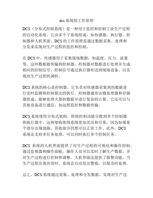
dcs系统的工作原理
DCS(分布式控制系统)是一种用于监控和控制工业生产过程的自动化系统。
它由多个子系统组成,如传感器、执行器、控制器和人机界面。
DCS的工作原理是通过数据采集、处理和
分发来实现对生产过程的监控和控制。
在DCS中,传感器用于采集现场数据,如温度、压力、流量等。
这些数据被传输到控制器,控制器对数据进行处理并生成相应的控制信号。
控制信号通过执行器传送到现场设备,以实现对生产过程的调控。
DCS系统的核心是控制器,它负责对传感器采集到的数据进
行实时监测和控制算法的执行。
控制器通常由微处理器和存储器组成,能够处理大量的数据并进行复杂的计算。
它还可以与其他设备进行通信,如远程监控和数据传输。
DCS系统使用分布式架构,即将控制功能分散到多个控制器
和执行器中。
这种架构使得系统更加灵活和可靠,因为如果某个部分出现故障,其他部分仍然可以正常工作。
此外,DCS
系统还支持多任务处理,可以同时执行多个控制任务。
DCS系统的人机界面提供了对生产过程的可视化和操作控制。
通过监视器和操作面板,操作人员可以实时了解生产数据,并对生产过程进行控制和调整。
人机界面还提供了报警功能,当生产过程出现异常时,系统会自动发出警报,以便及时处理。
总之,DCS系统通过采集、处理和分发数据,实现对生产过
程的监控和控制。
它的分布式架构和人机界面使得生产过程更加可靠、高效和安全。
XES-07励磁控制器人机界面说明
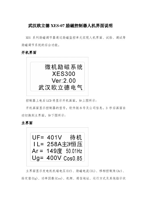
武汉欧立德XES-07励磁控制器人机界面说明XES系列励磁调节器通过励磁监控单元实现人机界面、试验、调试等励磁调节系统的后台功能。
开机界面控制器上电后LCD将显示开机画面,如上图所示:开机画面显示控制器的型号,软件版本号及公司信息。
3秒后画面自动切换到主界面。
如下图所示:主界面主界面显示发电机机端电压(Uf)、励磁电流(IL)、移相控制角(Ar)、给定值(Ug)、功率因数(Cos)、机频、通信地址、运行方式及其他指示状态。
给定参数修改界面在主界面按“上移键”或“下移键”进入到“给定参数修改界面”,如下图所示:进入此界面后,当前给定参数反白显示,表白此参数处于修改状态;按“上移键”或“下移键”可增减当前给定参数;修改后按“确认键”,修改有效,发电机按新给定值运行;否则按“返回键”,修改无效,给定值自动恢复到修改前的值。
测量界面在主界面按“左移键”进入到“测量显示界面”,如下图所示:测量显示界面共显示9项电测量参数,分别如下表所示:按“上移键”或“下移键”可循环滚动显示相关测量参数;按“确认键”或“返回键”返回到主界面。
密码输入界面在主界面按“菜单键”进入到密码输入界面,如下图所示:按“左移键”或“右移键”移动光标到相应的数字。
按“确认键”输入密码,密码为4位数字。
按“取消键”退出到主界面。
菜单选择界面当在密码输入界面,输入4位数密码并正确,将进入到菜单选择界面,如下图所示:按“上移键”或“下移键”移动光标。
按“确认键”进入光标所指示对应的界面,按“退出键”直接返回到主界面。
运行方式界面按“上移键”或“下移键”移动光标。
按“确认键”将控制器运行方式切换到光标所指示对应模式,并返回到菜单选择界面;按“退出键”直接返回到菜单选择界面,运行方式不进行切换,保持原来运行方式。
PID参数输入界面按“上移键”或“下移键”移动光标。
按“左移键”或“右移键”修改当前光标所指项参数。
按“确认键”保存参数并退出;按“退出键”不保存参数并退出。
- 1、下载文档前请自行甄别文档内容的完整性,平台不提供额外的编辑、内容补充、找答案等附加服务。
- 2、"仅部分预览"的文档,不可在线预览部分如存在完整性等问题,可反馈申请退款(可完整预览的文档不适用该条件!)。
- 3、如文档侵犯您的权益,请联系客服反馈,我们会尽快为您处理(人工客服工作时间:9:00-18:30)。
O
O O O O O O O O O O O O O
各种控制装置的使用情况比较
使用 情况 需要 的空 间 编码 视觉 辨别 位置 触觉 辨别 位置 按钮 旋钮 旋转 跨钮 旋纽 开关 中 好 纽子 手摇 开关 把 小 较好 操纵 杆 子轮 踏板
小 好
小-中 较小 好 差
中-大 中-大 较好 好
大 较右方移动时, 圆形的或水平的显示 器的指针也应向左移动. 在直方向显示器, 指针应 向上移动. • 2. 当控制器向上或向前运动时, 指针应向上或向 右运动. • 3. 右手转或顺时针转意味着增加, 所以显示器也 应该显示增加. • 4. Hoyos推荐对于圆盘移动式显示器, 当控制器向 右移动时, • 刻度应向右移动, 但是刻度从左到右应 是增加的, 这样向右转可以使读数增大. • 5. 当控制器向上, 向前, 或向右移动时, 显示器的 读数应增大, 或开关应当在‘开’的位置, 为了使 读数减少, 或关掉开关, 控制器的手柄应向内, 或向 左, 或向下移动。
3.控制器的选择原则
• 1)快速而精确度高的操作一般采用手控或指控 装置,用力的操作则采用手臂及下肢控制; 2)手控制器应安排在肘和肩高度之间且容易接 触到的位置,并且易于看见; 3)紧急制动的控制器要尽量与其他控制器有明 显区分,避免混淆; 4)控制器的类型及方式应尽可能适合人的操作 特性,避免操作失误。
控制器的类型及选择
• 一、控制器的类型 • 1.按操纵方式划分 1)手动控制器 2)脚动控制器 • 2.按控制器的功能划分 1)开关控制器。 2)转换控制器。 3)调整控制器。 二、控制器的选择 4)制动控制器。 • 1.按功能选择 3.其他控制器
• 各种控制装置的使用功能
控制装置名 称 按钮 钮子开关 旋钮选择开 关 旋钮 踏钮 踏板 曲柄 手轮 操纵杆 键盘 启动 O O 不连续调节 O 使用功能 定量调节 连续控制 输入数据
二、控制运动方向与系统的关系
操纵控制与 系统反应 的对应方向
操作准确性与控制器操纵方向及系统反应方向关系
系统反应方 向 控制器操作 方向 向上 向前(离开 自己) 从下往上 向侧面(向 左和向右) 操作错误数占实验总数的百 分数 单手操作 双手操作 5.0 7.0 7.5 11.7 11.3 13.3 8.8 15.3 18.5 19.8
控制器的设计原则
• 一. 习惯问题 • 1. 当控制器向右方移动时, 圆形的或水平的显示器的指 针也应向左移动. 在 • 直方向显示器, 指针应向上移动. • 2. 当控制器向上或向前运动时, 指针应向上或向右运 动. • 3. 右手转或顺时针转意味着增加, 所以显示器也应该 显示增加. • 4. Hoyos推荐对于圆盘移动式显示器, 当控制器向右 移动时, • 刻度应向右移动, 但是刻度从左到右应是增加的, 这样向右转可以使读数增大. • 5. 当控制器向上, 向前, 或向右移动时, 显示器的读数 应增大, 或开关应当在'开'的位置, 为了使读数减少, 或关 掉开关, 控制器的手柄应向内, 或向左, 或向下移动,.
小区域连续性装置 大区域连续性装置
用于追踪的控制装置选择
追踪信号的运动形 适宜的控制器类型 式 圆形 圆形转动 直线 圆形转动 直线 直线移动 圆形 直线移动 方案比较 最好 好 中等 一般
一、控制器信息的反馈
• • • • 1)光显示。 2)振动变化。 3)音响显示。 4)操纵阻力。
不同控制器所要求的最小阻力
• 2.大小编码 3.位置编码 4.色彩编码 5.符号编码 • 控制器上的编码(汽车门)
四、操作控制系统的安全因素
• l.操作误差的种类
• 1)置换差错。 2)调节错误。 • 3)逆转错误。 4)无意的操作错误。
2.操作误差的相关因素
• 1)手套 2)鞋 3)工作服
• 工作服装的作用: ①保证人的生命得以正常维持。 ②为生产劳动提供最大的方便,有利于提 高工作效率。 ③保障操作系统安全。
向后(向自 己) 向下
控制器的编码
• • • • • • • 1. 形状编码. 2. 大小编码. 3. 位置编码. 4. 颜色编码. 5. 标号编码. 6. 安置. 7. 结构和材料.
三、控制器编码
• 1.形状编码 • 1)形状编码要尽量简单易识别。实验证明,简 单的形状要比复杂形状识别的准确性高,易记忆, 识别速度快。 2)形状编码的形态设计要尽量与其使用功能的 特点相吻合,以使人容易识别控制器的功能和用 途。 3)控制器的形状编码的手感要好,不会引起人 的不舒适;当戴手套操作时,也应能较好地分辨 和使用。
美国空军常用的控制器形状编码
海军雷达系统中常用的控制钮
常用的旋钮控制器
• 连续旋转钮 (控制范围超过360o), 见图(a)(b); • 部分旋转钮 (控制范围不超过360o), 见(c); • 定位指示旋钮 (控制范围有固定的边界限范围 有固定的边界限制) 见图(d)。
(a)
(b)
(c)
Mirror-image controls
大 差
可
好
差
好
好
可
好
较好
差
差
可
可
好
好
可
较好
较好
较好
一排 类似 控制 装置 的检 查 一排 控制 装置 的操 作 合并 控制
差 好 差 好 好 差 好 差 差
好 差 差 差 好 差 好 差 差 较 好 好 差 好 差 好 好 差 好
不同工作情况下选择控制装置的建议
工作情况
操 纵 力 较 小 情 况 操 纵 力 较 大 情 况
建议使用的控制器 按钮、踏钮、拨动开关、摇动开关 按钮、拨动开关、旋钮、选择开关
同心成层旋钮、键盘、拨动开关、旋转选 择开关 25 个以上分开的装置 键盘 小区域的连续装置 旋钮
较大区域的连续装置
2 个分开的装置 4 个分开的装置 4 - 24 个分开的 装置
2 个分开的装置
3-24 个分开的装置
曲柄 扳手、杠杆、大按钮、踏钮 扳手、杠杆 手轮、踏板、杠杆 大曲柄
控制器类型 手动按钮 扳动开关 旋转选择开关 旋纽 摇柄 手轮 手柄 脚动按钮 脚踏板 所需最小阻力 2.8 2.8 3.3 0~1.7 9~22 22 9
5.6( 如果脚停留在控制器上 ) 17.8( 如果脚不停留在控制器上 ) 44.5( 如果脚停留在控制器上 ) 17.8( 如果脚不停留在控制器上 )