感应加热DIY教程
5千瓦电磁感应加热炉制作方法

5千瓦电磁感应加热炉制作方法全文共四篇示例,供读者参考第一篇示例:5千瓦电磁感应加热炉是一种高效的加热设备,运用电磁感应原理将电能转化为热能,广泛应用于金属加热、熔炼、焊接等工业领域。
下面将介绍一种制作5千瓦电磁感应加热炉的方法,希望能够对您有所帮助。
我们需要准备以下材料和工具:1. 电磁感应加热线圈2. 电磁感应加热器控制器3. 电源线4. 绝缘胶带5. 小型金属容器6. 不锈钢管7. 绝缘材料8. 电动工具接下来,我们可以按照以下步骤进行制作:第一步:制作电磁感应加热线圈将不锈钢管捆绑在一起形成一个圆圈,确保每根管子之间的间距均匀。
然后,将绝缘材料包裹在管子外部,用绝缘胶带固定。
将电磁感应加热线圈连接到电磁感应加热器控制器。
第二步:安装电磁感应加热线圈将电磁感应加热线圈安装在金属容器底部或侧面,确保线圈与容器之间的距离适当,以便加热效果更好。
第三步:连接电源线将电源线连接到电磁感应加热器控制器,并将另一端插入电源插座,注意接线的正确性和稳固性。
第四步:测试在启动电磁感应加热炉之前,需要进行一次简单的测试。
将容器中放入一些金属材料,启动电磁感应加热器控制器,观察加热效果和加热速度是否符合要求。
第五步:使用和维护在使用电磁感应加热炉时,需要注意安全,避免触碰加热器控制器和线圈。
定期检查设备运行状况,保持设备清洁,确保设备正常使用。
通过以上步骤,我们就可以制作一台5千瓦电磁感应加热炉了。
这种加热设备具有加热速度快、效率高、节能环保等优点,适用于许多工业领域的加热需求。
希望这份制作方法对您有所启发,欢迎尝试制作并应用于实际生产中。
【如果想了解更多详细制作方法,还可以参考相关资料或咨询专业人士】。
第二篇示例:5千瓦电磁感应加热炉是一种高效节能的加热设备,广泛应用于工业生产和材料加工领域。
本文将介绍一种简便易行的5千瓦电磁感应加热炉制作方法,希望能为您提供一些参考。
一、所需材料及工具准备1. 5千瓦电磁感应加热炉主体:加热线圈、电容器、电容器放电电阻、电源控制器等。
高频加热感应线圈制作方法
高频加热感应线圈制作方法
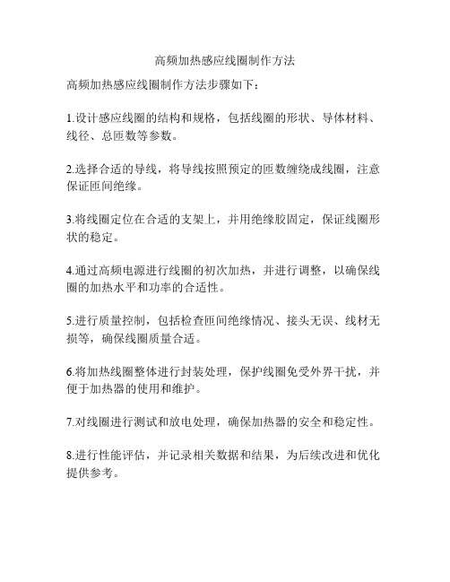
高频加热感应线圈制作方法步骤如下:
1.设计感应线圈的结构和规格,包括线圈的形状、导体材料、线径、总匝数等参数。
2.选择合适的导线,将导线按照预定的匝数缠绕成线圈,注意保证匝间绝缘。
3.将线圈定位在合适的支架上,并用绝缘胶固定,保证线圈形状的稳定。
4.通过高频电源进行线圈的初次加热,并进行调整,以确保线圈的加热水平和功率的合适性。
5.进行质量控制,包括检查匝间绝缘情况、接头无误、线材无损等,确保线圈质量合适。
6.将加热线圈整体进行封装处理,保护线圈免受外界干扰,并便于加热器的使用和维护。
7.对线圈进行测试和放电处理,确保加热器的安全和稳定性。
8.进行性能评估,并记录相关数据和结果,为后续改进和优化提供参考。
磁铁加热器制作方法
磁铁加热器制作方法磁铁加热器是一种常见的DIY加热装置,可以用来加热各种物品,如饮水、食物等。
下面,本文将介绍磁铁加热器的制作方法。
一、材料准备1、磁铁:选择直径约5厘米的圆形磁铁,可在电子市场或网络购物平台购买。
2、电烙铁:用于焊接磁铁和电线,推荐使用30W-50W的电烙铁。
3、电线:选择1.5平方毫米左右的电线,注意电线的长度要足够。
4、温控器:用于控制磁铁加热器的温度,推荐使用数字温控器。
5、铝板:选择厚度为1毫米左右的铝板,可以在市场上购买。
二、制作过程1、焊接磁铁将两个磁铁的极性相反地吸附在一起,用电烙铁从底部开始焊接两个磁铁的连接处,使其稳固地连接在一起。
2、固定电线在磁铁加热器的一个切面上钻两个小孔,分别穿过两段电线,固定在磁铁上。
使用电烙铁焊接电线和磁铁连接处,确保连接牢固。
3、连接温控器将电线通过温控器连接,将温控器放在磁铁上,通过电线连接到磁铁加热器。
使用电烙铁焊接电线和温控器连接处。
4、加热铝板将切好的铝板放在磁铁的切口处,将磁铁加热器通电,调节温控器的温度,待铝板加热到所需温度后即可使用。
三、注意事项1、在制作过程中,要注意安全,避免发生烫伤等意外。
2、切割铝板时要保持手部稳定,避免切伤手部。
3、在使用磁铁加热器时,要注意温度和时间,不能过度加热和长时间使用,以免造成伤害。
4、在不使用磁铁加热器时,要及时断电,并注意存放位置,避免微波炉等金属器具同时存在。
总之,磁铁加热器是一种制作简单、方便实用的DIY加热装置,适用于各种场合,希望本文的介绍能为您提供一些参考。
磁铁加热器制作方法

磁铁加热器制作方法步骤1:准备材料和工具1.1:准备一个铁座,用于安装磁铁和加热材料。
1.2:准备两块强力磁铁。
1.3:准备一个加热材料,例如铁块或石墨棒。
1.4:准备一把火柴或打火机作为点火工具。
1.5:准备一块保护板和一块隔热材料。
步骤2:制作磁铁装置2.1:将铁座放在平整的工作台上。
2.2:将两块强力磁铁叠放在一起,确保磁性相同的两面朝向外侧。
2.3:用胶水或胶带将两块磁铁固定在铁座上。
步骤3:安装加热材料3.1:将加热材料放在磁铁之间的缝隙中。
确保加热材料与磁铁接触紧密,以便热量传导更好。
3.2:用保护板将加热材料覆盖起来,以防止飞溅和伤害。
步骤4:点火和加热4.1:用火柴或打火机点燃加热材料。
4.2:当加热材料开始发热时,用隔热材料将磁铁加热器包裹住,以保持热量。
4.3:等待一段时间,使加热材料足够热,以供你所需要的应用。
步骤5:注意事项5.1:在制作和使用磁铁加热器时,务必注意安全。
加热材料会变得非常热,避免直接接触和烫伤。
5.2:加热器会产生烟雾和有害气体,请确保在通风良好的地方使用,并避免长时间暴露于这些气体中。
5.3:在使用加热器时,尽量避免将其放置在易燃物附近,以防引起火灾。
总结:以上是一个简单的磁铁加热器制作方法。
请记住,在制作和使用任何自制加热设备时,始终要注意安全。
使用时要小心,以免烫伤或引发其他意外。
如果你对自己的制作能力没有信心,最好购买专业制造的加热设备,以确保安全和有效的加热效果。
感应加热DIY教程
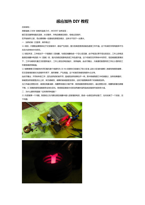
感应加热DIY教程总体架构:串联谐振2.5KW 锁相环追频ZVS,MOSFET全桥逆变;磁芯变压器两档阻抗变换,水冷散热,市电自耦调压调功,母线过流保护。
在开始制作之前,有必要明确一些基础性原理及概念,这样才不至于一头雾水。
一.加热机制〔扫盲用,高手跳过〕1.1涡流,只要是金属物体处于交变磁场中,都会产生涡流,强大的高密度涡流能迅速使工件升温。
这个机制在所有电阻率不为无穷大的导体中均存在。
1.2感应环流,工件相当于一个短路的1匝线圈,与感应线圈构成一个空心变压器,由于电流比等于匝比的反比,工件上的电流是感应线圈中电流的N〔匝数〕倍,强大的感应短路电流使工件迅速升温。
这个机制在任何导体中均存在,恒定磁通密度情况下,工件与磁场矢量正交的面积越大,工件上感生的电流越大,效率越高。
由此可看出,大磁通切割面积的工件比小面积的工件更容易获得高温。
1.3磁畴摩擦〔在铁磁体内存在着无数个线度约为10-4m的原本已经磁化了的小区域,这些小区域叫磁畴〕,铁磁性物质的磁畴,在交变磁场的磁化与逆磁环作用下,剧烈摩擦,产生高温。
这个机制在铁磁性物质中占主导。
由此可看出,不同材料的工件,因为加热的机制不同,造成的加热效果也不一样。
其中铁磁物质三中机制都占,加热效果最好。
铁磁质加热到居里点以上时,转为顺磁性,磁畴机制减退甚至消失。
这时只能靠剩余两个机制继续加热。
当工件越过居里点后,磁感应现象减弱,线圈等效阻抗大幅下降,致使谐振回路电流增大。
越过居里点后,线圈电感量也跟着下降。
LC回路的固有谐振频率会发生变化。
致使固定激励方式的加热器失谐而造成设备损坏或效率大减。
二.为什么要采用谐振?应采用何种谐振?2.1先答复第一个问题。
我曾经以为只要往感应线圈中通入足够强的电流,就成一台感应加热设备了。
也对此做了一个实验,见下列图。
实验中确实有加热效果,但是远远没有到达电源的输出功率应有的效果。
这是为什么呢,我们来分析一下,显然,对于固定的工件,加热效果与逆变器实际输出功率成正比。
感应加热ZVS制作图解
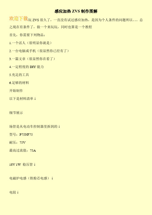
感应加热ZVS制作图解玩ZVS很久了,一直没有试过感应加热,是因为个人条件的问题所以。
总之现在有条件了,做一个来玩玩,同时也算是一个教程首先,你需要下列物品:1.一个活人(很明显你就是)2.一台电脑或手机(很显然你已经有了)3.一篇文章(很显然你在看了)4.一定程度的DIY能力5.充足的工具6.足够的材料开始制作以下是材料清单↓细节展示场管是从电动车控制器里拆到的↓型号:P75NF75耐压:75V最高过流值:75A18V 1W 稳压管↓电磁炉电感(铁粉芯电感)↓电阻↓洞洞板↓问答区{小白:稳压管不是应该用12V的吗,为什么要用18V的作者:普通场效应晶体管的G极耐压一般低于30V,一般高于18V,一旦G极所加的电压高于它的耐压值,G极就会击穿,所以要加稳压管来保护场效应晶体管的G极,防止击穿,所以12V到18V的稳压管都可以采用,但是我们的供电电压是12V,稳压管的稳压值应该略大于电源电压,所以采用18V的稳压管,因为我们要用于感应加热,浪涌比较大,所以采用1W的稳压管。
小白:330Ω的电阻不是应该用大功率的吗?为什么用小功率的?作者:95%以上的人都被迷惑了(就连我当初也被迷惑了),其实电阻应该用330Ω的而不是470Ω,在这里我要科普一下,电流=电压÷电流,按照这个公式,12V供电,通过330Ω电阻的电流也就36Ma,烧不了的。
小白:稳压管不是两个就够了吗?为什么要用四个?作者:因为我们要用两个稳压管组成双向稳压管,所以要用四个。
}好的问答区结束,正文继续。
注意!所有元件建议先检查一遍后再开始做,确保安全。
我们先把电感绕好,用1MM粗的漆包线绕20圈即可↓下面是电路图↓(我们要做到电路其实略有修改,这张图仅供参考)四管无抽头版本,高端玩家可以试试↓下面是布线,看不懂别怪我↓注:蓝色跳线是电感因为我们是要外置散热(把管子放到洞洞板外面散热),所以先在板子上打六个洞↓然后把10K电阻焊到指定位置↓接着把两个稳压管的负极焊在一起↓剪掉多余的部分↓焊在指定的位置↓由于已经是双向的稳压管了,可以随便焊,不分正负然后把330Ω电阻也焊上↓背面↓(比螃蟹的好多了)把UF4007也焊上↓焊另外一个的时候如果引脚不够长的话可以这样加长↓焊上↓至此所有小体积元件已经焊好了,下面开始焊背面的走线有些地方电流比较大,而然一些小白可能不知道是哪里,所以我对电路图处理了一下,红色部分是大电流部分,要加粗!↓↓↓↓↓↓↓准备好线材↓把绝缘皮去掉↓取一定长度,焊上↓这地方电流很大,这个是负极端,电流的出口,为了保险一点还是镀点锡比较好↓(烙铁不好别镀)接下来把电感焊上,注意不要碰到其他元件的引脚↓把电容也给焊上,由于我的洞洞板不够大,所以用两张合起来,先把边缘修剪一下↓这里大家可以跳过电容已经焊完了↓接下来把接线柱焊上↓加强一下↓好现在板子已经焊完了,接下来搞散热CPU散热器↓之前买了一个新的散热器,所以这个被替换下来了把支架搞成如图所示的样子↓准备一小片散热片,如果你的场效应晶体管比较大,那么就需要两片↓导热硅脂↓买CPU散热器送的,能用就是了先在管子被面涂点↓手头上没有好的绝缘垫,就用纸代替了,好孩子不要学我↓把管子放上,把线焊好,线要粗的线↓我遇到了毛刺↓我本来想割掉的,结果大力出奇迹,D极断了↓无奈之下只好直接焊到管子的散热片上↓把线全部接好↓在管子上面涂点硅脂↓在上面再垫一层纸↓小散热片上涂点硅脂↓然后把小散热片压到纸上再把支架压到小散热片上再扣好支架,然后就好了↓下面开始接线注意不要虚焊,也不要焊错↓用一根绳子把散热器和板子绑在一起↓连接好电源线↓用铜线做一个加热线圈(5+5圈)↓应该先接线圈再绑散热器的,诶↓下面开始测试供电12V蓄电池↓风扇由可调电源供电↓电池很久没有充电了,电压只有12.9V↓总面貌↓测试,锯片5秒烧红,电池满电的话可能会更快点↓加热的时候电压被拉到了11.7V↓然而那片小散热片还是蛮烫的,而CPU散热器的散热片却摸不出温度,说明导热差于是我把它拆了出来,结果看到其中一个管子的接线掉了↓这。
自制简易高频感应加热
自制简易高频感应加热感应加热简介电磁感应加热,或简称感应加热,是加热导体材料比如金属材料的一种方法。
它主要用于金属热加工、热处理、焊接和熔化。
顾名思义,感应加热是利用电磁感应的方法使被加热的材料的内部产生电流,依靠这些涡流的能量达到加热目的。
感应加热系统的基本组成包括感应线圈,交流电源和工件。
根据加热对象不同,可以把线圈制作成不同的形状。
线圈和电源相连,电源为线圈提供交变电流,流过线圈的交变电流产生一个通过工件的交变磁场,该磁场使工件产生涡流来加热。
感应加热原理感应加热表面淬火是利用电磁感应原理,在工件表面层产生密度很高的感应电流,迅速加热至奥氏体状态,随后快速冷却得到马氏体组织的淬火方法,当感应圈中通过一定频率的交流电时,在其内外将产生与电流变化频率相同的交变磁场。
金属工件放入感应圈内,在磁场作用下,工件内就会产生与感应圈频率相同而方向相反的感应电流。
由于感应电流沿工件表面形成封闭回路,通常称为涡流。
此涡流将电能变成热能,将工件的表面迅速加热。
涡流主要分布于工件表面,工件内部几乎没有电流通过,这种现象称为表面效应或集肤效应。
感应加热就是利用集肤效应,依靠电流热效应把工件表面迅速加热到淬火温度的。
感应圈用紫铜管制做,内通冷却水。
当工件表面在感应圈内加热到一定温度时,立即喷水冷却,使表面层获得马氏体组织。
感应电动势的瞬时值为:式中:e瞬时电势,V;零件上感应电流回路所包围面积的总磁通,Wb,其数值随感应器中的电流强度和零件材料的磁导率的增加而增大,并与零件和感应器之问的间隙有关。
为磁通变化率,其绝对值等于感应电势。
电流频率越高,磁通变化率越大,使感应电势P 相应也就越大。
式中的负号表示感应电势的方向与的变化方向相反。
零件中感应出来的涡流的方向,在每一瞬时和感应器中的电流方向相反,涡流强度取决于感应电势及零件内涡流回路的电抗,可表示为:式中,I涡流电流强度,A;Z自感电抗,;R零件电阻,;X阻抗,。
电磁感应原理的应用制作
电磁感应原理的应用制作简介电磁感应是一种重要的物理现象,通过电磁感应原理,可以制作各种各样的设备和技术。
本文将介绍几种常见的电磁感应原理的应用制作。
1. 发电机发电机是利用电磁感应原理制作的设备,可以将机械能转化为电能。
具体制作步骤如下:•步骤一:准备一个磁铁和一段导线。
•步骤二:将导线绕在磁铁上,形成一个线圈。
•步骤三:将线圈的两端连接到一个环形导体上。
•步骤四:将磁铁旋转,使磁铁的磁场穿过线圈。
•步骤五:由于磁场的变化,线圈中会产生感应电流,从而实现发电。
2. 变压器变压器是利用电磁感应原理制作的设备,可以实现电能的变压。
具体制作步骤如下:•步骤一:准备两个线圈,一个称为初级线圈,一个称为次级线圈。
•步骤二:将两个线圈交错放置在一个铁芯上。
•步骤三:将初级线圈连接到交流电源上。
•步骤四:当通过初级线圈的电流变化时,产生变化的磁场。
•步骤五:由于次级线圈与初级线圈共享同样的磁场,次级线圈会感应出电流,实现电能的变压。
3. 传感器传感器是利用电磁感应原理制作的设备,可以感知和测量周围环境的物理量。
具体制作步骤如下:•步骤一:选择合适的传感器类型和工作原理,如磁传感器、电感传感器等。
•步骤二:根据传感器的工作原理,选择合适的电路和元件。
•步骤三:组装电路和元件,构建传感器系统。
•步骤四:校准传感器系统,确保测量结果准确。
•步骤五:将传感器系统与其他设备或系统连接,实现数据的采集和分析。
4. 电磁炉电磁炉是利用电磁感应原理制作的设备,可以通过电磁感应加热食物或饮水。
具体制作步骤如下:•步骤一:准备一个感应线圈和一个高频电源。
•步骤二:将感应线圈连接到高频电源上。
•步骤三:将锅具放在感应线圈上方,确保锅具的底部与感应线圈保持一定的距离。
•步骤四:打开高频电源,产生高频电流。
•步骤五:由于感应线圈中产生变化的磁场,锅具底部的金属材料会发生感应加热。
5. 电磁刹车电磁刹车是利用电磁感应原理制作的设备,可以实现制动和停止旋转物体。
中频感应加热热处理操作步骤

中频感应加热热处理操作步骤嗨,宝子们!今天来唠唠中频感应加热热处理的操作步骤哈。
咱先得把设备检查好。
看看中频感应加热设备有没有啥明显的损坏呀,那些电线啥的有没有破损或者松动的情况。
这就好比出门前要检查自己衣服有没有破洞一样重要呢。
还有控制装置,按一按那些按钮,看看显示屏啥的是不是正常工作,要是这一步没做好,后面可就容易出乱子啦。
接下来呢,就是要把需要热处理的工件准备好。
工件表面得干净整洁,不能有油污、铁锈这些脏东西哦。
就像咱洗脸一样,脸不干净,擦啥护肤品都不好使。
你可以用一些简单的清洁工具把工件表面清理干净,这可是保证热处理效果的关键呢。
再然后呀,把工件放到合适的位置上。
这个位置可不能乱放,得根据设备的要求来。
就像玩拼图一样,每个块都有它该在的地方。
要确保工件和感应线圈之间的距离合适,太近了可能会出现一些意外情况,太远了又加热效果不好。
之后就可以启动设备啦。
不过在启动的时候,要慢慢调整功率和频率这些参数哦。
这就像炒菜的时候慢慢调整火候一样,不能一下子开太大。
根据工件的材料、大小和热处理的要求,找到最适合的参数值。
这个过程可能需要一点经验和耐心,但是多试几次就好啦。
在加热的过程中,眼睛可不能闲着。
要时刻盯着设备的运行状态,看看温度是不是按照预期在上升。
要是发现有啥不对劲的地方,像温度突然升得特别快或者设备发出奇怪的声音,就得赶紧采取措施,可不能让小问题变成大麻烦。
等加热到了规定的温度和时间后,就可以停止加热啦。
但是这还没完哦,还得让工件进行适当的冷却。
冷却的方式也有讲究呢,有的工件需要快速冷却,有的则需要慢慢冷却。
这就像不同的人睡觉盖被子的厚度不一样,得根据具体情况来。
最后呢,把处理好的工件取出来,再检查一下质量。
看看热处理后的工件是不是达到了预期的效果,硬度、韧性这些性能指标有没有符合要求。
如果没达到,就得分析分析是哪个步骤出了问题,下次改进。
好啦,这就是中频感应加热热处理的操作步骤啦,是不是还挺有趣的呢?。
电磁感应加热器的制作方法

电磁感应加热器的制作方法一、引言电磁感应加热器是通过电磁感应原理实现加热的设备,它可以将电能转化为热能,广泛应用于工业生产和日常生活中。
本文将介绍电磁感应加热器的制作方法。
二、材料准备制作电磁感应加热器需要准备以下材料:1. 铜线:用于制作发电线圈;2. 铁芯:用于增强磁场;3. 电容器:用于储存电能;4. 散热器:用于散热;5. 控制电路:用于控制电磁感应加热器的工作。
三、制作过程1. 制作发电线圈:将铜线绕在一个绝缘材料上,绕成线圈状。
线圈的大小和形状可以根据具体需求进行设计。
绕好线圈后,将线圈两端的铜线固定好,确保其不松动。
2. 安装铁芯:将制作好的发电线圈放入铁芯中。
铁芯可以是一个铁环,也可以是其他形状的铁块。
铁芯的作用是增强磁场,提高电磁感应加热器的效果。
3. 连接电容器:将电容器与发电线圈连接起来。
电容器可以储存电能,使电磁感应加热器在供电中断时仍能继续工作。
4. 安装散热器:将散热器安装在电磁感应加热器的发电线圈和电容器附近,用于散热。
由于电磁感应加热器在工作过程中会产生一定的热量,散热器的存在可以有效降低设备的温度,保证其正常运行。
5. 连接控制电路:将控制电路与发电线圈和电容器连接起来。
控制电路可以根据需要设计,用于控制电磁感应加热器的工作状态和加热功率。
四、工作原理电磁感应加热器的工作原理是利用电磁感应现象,即当导体在磁场中运动时,会产生感应电动势,从而产生感应电流,进而产生热能。
具体来说,当电磁感应加热器通电后,发电线圈中的电流会产生磁场,磁场会使铁芯磁化,进而产生感应电流。
感应电流在发电线圈中流动时,会产生磁场,磁场的变化又会产生感应电流,如此循环往复,最终导致发电线圈中的电能转化为热能。
五、应用领域电磁感应加热器广泛应用于工业生产和日常生活中。
在工业生产中,它可以用于金属加热、熔化、焊接等工艺;在日常生活中,它可以用于电磁炉、电热水壶等家电产品中。
六、总结通过制作电磁感应加热器,我们可以将电能有效地转化为热能,实现加热的目的。
感应加热ZVS制作图解
这个帖子我从9点半开始编辑到凌晨两点才弄完
最后给大家看看我的SSTC(再过几周我就发帖了)
THE END
小白:330Ω的电阻不是应该用大功率的吗?为什么用小功率的?
作者:95%以上的人都被迷惑了(就连我当初也被迷惑了),其实电阻应该用330Ω的而不是470Ω,在这里我要科普一下,电流=电压÷电流,按照这个公式,12V供电,通过330Ω电阻的电流也就36Ma,烧不了的。
小白:稳压管不是两个就够了吗?为什么要用四个?
在管子上面涂点硅脂↓
在上面再垫一层纸↓
小散热片上涂点硅脂↓
然后把小散热片压到纸上
再把支架压到小散热片上
再扣好支架,然后就好了↓
下面开始接线
注意不要虚焊,也不要焊错↓
用一根绳子把散热器和板子绑在一起↓
连接好电源线↓
用铜线做一个加热线圈(5+5圈)↓
应该先接线圈再绑散热器的,诶↓
下面开始测试
供电12V蓄电池↓
感应加热ZVS制作图解
玩ZVS很久了,一直没有试过感应加热,是因为个人条件的问题所以。。。总之现在有条件了,做一个来玩玩,同时也算是一个教程
首先,你需要下列物品:
1.一个活人(很明显你就是)
2.一台电脑或手机(很显然你已经有了)
3.一篇文章(很显然你在看了)
4.一定程度的DIY能力
5.充足的工具
6.足够的材料
准备一小片散热片,如果你的场效应晶体管比较大,那么就需要两片↓
导热硅脂↓买CPU散热器送的,能用就是了
先在管子被面涂点↓
手头上没有好的绝缘垫,就用纸代替了,好孩子不要学我↓
把管子放上,把线焊好,线要粗的线↓
我遇到了毛刺↓
感应加热器制作方法

感应加热器制作方法
感应加热器是一种利用电磁感应原理加热物体的装置。
它可以在没有直接接触或导电接触的情况下加热物体,因此具有广泛的应用领域,如工业加热、烹饪、医疗等。
制作一个简单的感应加热器需要以下步骤:
1. 准备材料:
- 磁性铁芯
- 铜线
- 电源线
- 开关
- 散热器
2. 制作线圈:
将铜线绕在磁性铁芯上,制作一个线圈。
线圈的大小和圈数可以根据需要进行调整。
确保线圈的每一圈都紧密相连,没有空隙。
3. 连接电源线:
将电源线与线圈的两端连接起来,通过焊接或其它方法进行固定。
确保连接牢固并正确接触,以保证电流正常流动。
4. 安装开关:
在电源线上安装一个开关,用于控制电流的通断。
确保开关的质量可靠,并使其易于操作。
5. 安装散热器:
将散热器安装在磁性铁芯的周围,用于散热和保护装置。
选择合适的散热器以确保加热器的稳定工作和长寿命。
完成上述步骤后,感应加热器的制作就完成了。
当通电时,电流经过线圈会产生磁场,磁场会感应铁芯中的涡流。
涡流会产生热量,从而加热了对应的物体。
在使用感应加热器时,要注意安全,避免触摸线圈和高温物体。
总结一下,感应加热器制作的关键是制作合适的线圈和连接电源线。
正确操作和注意安全性可以确保加热器的有效工作。
随着技术的不断发展,感应加热器将会在各个领域得到更广泛的应用和进一步的改进。
5千瓦电磁感应加热炉制作方法

5千瓦电磁感应加热炉制作方法全文共四篇示例,供读者参考第一篇示例:5千瓦电磁感应加热炉是一种高效、节能、环保的加热设备,广泛应用于工业生产中。
下面我们就来介绍一下5千瓦电磁感应加热炉的制作方法。
一、设备准备1. 磁感应加热炉主机:选择功率为5千瓦的电磁感应加热炉主机,确保加热效率和加热温度的稳定性。
2. 冷却系统:准备水冷却系统,确保设备在工作过程中的散热效果。
3. 控制系统:选购合适的控制系统,用于调节加热炉的加热功率和温度。
4. 冷却水泵和水箱:保证设备的冷却系统正常运作。
5. 电源线和接头:选择合适的电源线和接头,并确保电路连接正确。
二、组装设备1. 将磁感应加热炉主机安装在平整的地面上,确保设备稳固。
4. 启动设备,调节控制系统,确认设备功能正常。
三、使用方法1. 将需要加热的工件放置在加热炉内。
2. 根据工件的材质和加热要求,调节加热功率和温度。
3. 启动加热炉,待工件达到预定温度后关闭加热炉。
4. 取出加热后的工件,进行下一步处理。
四、注意事项1. 在使用加热炉时,应注意设备周围的安全防护,避免发生意外事故。
3. 定期检查加热炉的运行状态,保持设备的正常工作。
4. 使用加热炉时应遵守相关规定,确保设备的安全运行。
通过以上的介绍,相信大家对5千瓦电磁感应加热炉的制作方法有了更深入的了解。
希望这份文章对大家在工业生产中使用电磁感应加热炉有所帮助。
祝大家工作顺利,生产高效!第二篇示例:5千瓦电磁感应加热炉是一种常用的工业加热设备,主要用于加热金属材料,加工成型等工艺。
它的原理是利用电磁感应原理,通过感应加热的方式将金属材料加热至所需温度,从而实现加工成型目的。
今天我们将介绍一下5千瓦电磁感应加热炉的制作方法,帮助那些对此感兴趣的朋友们了解这一工艺的过程。
我们需要准备以下材料和工具:1台5千瓦电磁感应加热炉主机、金属容器、电源线、控制面板、感应线圈等。
接下来,我们开始制作5千瓦电磁感应加热炉。
老外自制的中频感应加热装置

DIY中频加热炉IntroductionInduction heating is a non-contact heating process. It uses highfrequency electricity to heat mat erials that are electricallyconductive. Since it is non-contact, the heating process does notcont aminate the material being heated. It is also very efficient sincethe heat is actually generated inside the workpiece. This can becontrasted with other heating methods where heat is generated in aflame or heating element, which is then applied to the workpiece. Forthese reasons Induction He ating lends itself to some uniqueapplications in industry.How does Induction Heating work ?A source of high frequency electricity is used to drive a largealternating current through a coil. This coil is known as the workcoil. See the picture opposite.The passage of current through this coil generates a very intenseand rapidly changing magnetic fi eld in the space within the work coil.The workpiece to be heated is placed within this intense al ternatingmagnetic field.Depending on the nature of the workpiece material, a number of things happen...The alternating magnetic field induces a current flow in theconductive workpiece. The arrangement of the work coil and theworkpiece can be thought of as an electrical transformer. The work coili s like the primary where electrical energy is fed in, and theworkpiece is like a single turn seco ndary that is short-circuited. Thiscauses tremendous currents to flow through the workpiece. Thes e areknown as eddy currents.In addition to this, the high frequency used in induction heatingapplications gives rise to a phe nomenon called skin effect. This skineffect forces the alternating current to flow in a thin laye r towardsthe surface of the workpiece. The skin effect increases the effectiveresistance of the m etal to the passage of the large current. Thereforeit greatly increases the heating effect caused by the current inducedin the workpiece.(Although the heating due to eddy currents is desirable inthis application, it is interesting to note that transformermanufacturers go to great lengths to avoid this phenomenon in theirtransform ers. Laminated transformer cores, powdered iron cores andferrites are all used to prevent eddy cu rrents from flowing insidetransformer cores. Inside a transformer the passage of eddy currents is highly undesirable because it causes heating of the magnetic core andrepresents power that is was ted.)And for Ferrous metals ?For ferrous metals like iron and some types of steel, there is anadditional heating mechanism tha t takes place at the same time as theeddy currents mentioned above. The intense alternating magne tic fieldinside the work coil repeatedly magnetises and de-magnetises the ironcrystals. This rapi d flipping of the magnetic domains causesconsiderable friction and heating inside the material. H eating due tothis mechanism is known as Hysteresis loss, and is greatest formaterials that have a large area inside their B-H curve. This can be alarge contributing factor to the heat generated during inductionheating, but only takes place inside ferrous materials. For this reasonferrous ma terials lend themselves more easily to heating by inductionthan non-ferrous materials.It is interesting to note that steel looses its magnetic materialswhen heated above approximately 700°C. This temperature is known as theCurie temperature. This means that above 700°C there ca n be no heatingof the material due to hysteresis losses. Any further heating of thematerial must be due to induced eddy currents alone. This makes heatingsteel above 700°C more of a challenge f or the induction heatingsystems. The fact that copper and Aluminium are both non-magnetic andvery good electrical conductors, can also make these materials achallenge to heat efficiently. (We wi ll see that the best course ofaction for these materials is to up the frequency to exaggerate los sesdue to the skin effect.)What is Induction Heating used for ?Induction heating can be used for any application where we want toheat an electrically conductive material in a clean, efficient andcontrolled manner.One of the most common applications is for sealing the anti-tamperseals that are stuck to the top of medicine and drinks bottles. A foilseal coated with "hot-melt glue" is inserted into the plas tic cap andscrewed onto the top of each bottle during manufacture. These foilseals are then rapid ly heated as the bottles pass under an inductionheater on the production line. The heat generated melts the glue andseals the foil onto the top of the bottle. When the cap is removed, thefoil re mains providing an airtight seal and preventing any tampering orcontamination of the bottle's con tents until the customer pierces thefoil.Another common application is "getter firing" to removecontamination from evacuated tubes such as TV picture tubes, vacuumtubes, and various gas discharge lamps. A ring of conductive materialcal led a "getter" is placed inside the evacuated glass vessel. Sinceinduction heating is a non-conta ct process it can be used to heat thegetter that is already sealed inside a vessel. An induction work coilis located close to the getter on the outside of the vacuum tube andthe AC source is tur ned on. Within seconds of starting the inductionheater, the getter is heated white hot, and chemi cals in its coatingreact with any gasses in the vacuum. The result is that the getterabsorbs any last remaining traces of gas inside the vacuum tube andincreases the purity of the vacuum.Yet another common application for induction heating is a processcalled Zone purification used in the semiconductor manufacturingindustry. This is a process in which silicon is purified by means of amoving zone of molten material. An Internet Search is sure to turn upmore details on this pr ocess that I know little about.Other applications include melting, welding and brazing or metals.Induction cooking hobs and ricecookers. Metal hardening of ammunition,gear teeth, saw blades and drive shafts, etc are also com monapplications because the induction process heats the surface of themetal very rapidly. Therefo re it can be used for surface hardening, andhardening of localised areas of metallic parts by "ou trunning" thethermal conduction of heat deeper into the part or to surroundingareas. The non cont act nature of induction heating also means that itcan be used to sterilise metal instruments by h eating them to hightemperatures whilst they are already sealed inside a known sterileenvironment in order to kill germs.What is required for Induction Heating ?In theory only 3 things are essential to implement induction heating:1. A source of High Frequency electrical power,2. A work coil to generate the alternating magnetic field,3.An electrically conductive workpiece to be heated,Having said this, practical induction heating systems are usually alittle more complex. For examp le, a matching network is often requiredbetween the High Frequency source and the work coil in or der to getgood power transfer. Water cooling systems are also common in highpower induction heate rs to remove waste heat from the work coil and itsmatching network. Finally some control electron ics is usually employedto control the intensity of the heating action, ensure consistentresults, and to protect the system from adverse operating conditions.However, the basic principle of opera tion of any induction heaterremains the same as described earlier.Practical implementationIn practice the work coil is usually incorporated into a resonanttank circuit. This has a number of advantages. Firstly, it makes eitherthe current or the voltage become sinusoidal. This minimis es losses inthe inverter by allowing it to benefit from eitherzero-voltage-switching or zero-curr ent-switching depending on the exactarrangement chosen. The sinusoidal waveform at the work coil alsorepresents a more pure signal and causes less Radio FrequencyInterference to nearby equipment. We will see that there are a numberof resonant schemes that the designer of an induction heater can choosefor the work coil:Series resonant tank circuitThe work coil is made to resonate at the intended operatingfrequency by means of a capacitor plac ed in series with it. This causesthe current through the work coil to be sinusoidal. The seriesre sonance also magnifies the voltage across the work coil, far higherthan the output voltage of the inverter alone. The inverter sees asinusoidal load current but it must carry the full current th at flowsin the work coil. For this reason the work coil often consists of manyturns of wire with only a few amps or tens of amps flowing.This arrangement is commonly used in things like rice cookers wherethe power level is low, and th e inverter is located next to the objectto be heated. The main drawbacks of the series resonant a rrangement arethat the inverter must carry the same current that flows in the workcoil. In additi on to this the series resonant action can become verypronounced if there is no workpiece presentto damp the circuit. Thisis not a problem in applications like rice cookers where the workpieceis always the same cooking vessel, and its properties are well known atthe time of design.The tank capacitor is typically rated for a high voltage because ofthe resonant voltage rise expe rienced in the series tuned resonantcircuit.Parallel resonant tank circuitThe work coil is made to resonate at the intended operatingfrequency by means of a capacitor plac ed in parallel with it. Thiscauses the current through the work coil to be sinusoidal. The parall elresonance also magnifies the current through the work coil, far higherthan the current capabili ty of the inverter alone. The inverter sees asinusoidal load current. However, in this case it on ly has to carry thepart of the load current that actually does real work. The inverterdoes not ha ve to carry the full circulating current in the work coil.This means that the work coil can be pl aced at a location remote fromthe inverter without incurring massive losses in the feed wires.It also means that work coils using this technique often consist offew turns of a thick copper co nductor but with large currents of manytens or hundreds of amps flowing. (This is necessary to ge t therequired Ampere turns to do the induction heating.) Water cooling iscommon for all but the s mallest of systems. This is needed to removeexcess heat generated by the passage of the large hig h frequencycurrent through the work coil and its associated tank capacitor.In the parallel resonant tank circuit the work coil can be thoughtof as an inductive load with a "power factor correction" capacitorinstalled across it. The PFC capacitor provides reactive curre nt flowequal and opposite to the inductive current drawn by the work coil.Therefore the only curr ent flow from the inverter is a small amountrequired to overcome losses in the "PFC" capacitor an d the work coil.There is always some loss in this tank circuit due to dielectric lossin the capac itor and skin effect causing resistive losses in the workcoil. Therefore a small current is alway s drawn from the inverter. Whena lossy workpiece is inserted into the work coil, this damps thepa rallel resonant circuit by introducing a further loss into thesystem. Therefore the current drawn by the parallel resonant tankcircuit increases when a workpiece is entered into the coil.Impedance matchingOr simply "Matching". This refers to the electronics that sitsbetween the source of high frequenc y power and the work coil we areusing for heating. In order to heat a solid piece of metal viaind uction heating we need to cause a TREMENDOUS current to flowin the surface of the metal. However this can be contrasted with theinverter that generates the high frequency power. The invertergene rally works better (and the design is somewhat easier) if itoperates at fairly high voltage but a low current. This allows commonswitch mode MOSFETs to be used. The comparatively low currents al somake the inverter less sensitive to layout and stray inductance. It isthe job of the matching n etwork and the work coil to transform the highvoltage/low current from the inverter to the low vo ltage/high currentrequired to heat the workpiece efficiently.We can think of the tank circuit incorporating the work coil (Lw) and its capacitor (Cw) as a parallel resonant circuit.This has a resistance (R) due to the lossy workpiece coupled intothe work coil due to the magneti c coupling between the two conductors.See the schematic opposite.In practice the resistance of the work coil, the resistance of thetank capacitor, and the resista nce of the workpiece all introduce aloss into the tank circuit and damp the resonance. Therefore it isuseful to combine all of these losses into a single "loss resistance."In the case of a paral lel resonant circuit this loss resistance appearsdirectly across the tank circuit. This resistanc e represents the onlycomponent that can consume power, and therefore we can think of thisloss res istance as the load that we are trying to drive power into asefficiently as possible.When driven at resonance the current drawn by the tank capacitor andthe work coil are equal and o pposite in phase and therefore cancel eachother out as far as the source of power is concerned. T his meansthat the only load presented to the power source at the resonantfrequency is the loss re sistance across the tank circuit.(Notethat, when driven either side of the resonant frequency, t here is anadditional "out-of-phase" component to the current caused by incompletecancellation of the work coil current and the tank cap current. Thisreactive current increases the total magnitud e of the current beingdrawn from the source but does not contribute to any useful heating inthe w orkpiece.)The job of the matching network is simply to transform thisrelatively large loss resistance acros s the tank circuit down to alower value that better suits the inverter attempting to drive it.The re are many different ways to achieve this impedance transformationincluding tapping the work coil, using a ferrite transformer, acapacitive divider in place of the tank capacitor, or a matching circuit such as an L-match network.In the case of an L-match network it can transform the relativelyhigh load resistance of the tank circuit down to something around 10ohms which better suits the inverter. This figure allows the inverterto run from several hundred volts whilst keeping currents down to areasonable level so th at standard switch-mode MOSFETs can be used toperform the switching operation.The L-match network consists of components Lm and Cm shown opposite.The L-match network also has another highly desirable property. TheL-match network provides a pro gressively rising inductive reactance toall frequencies higher than the resonant frequency of the tank circuit.This is very important when the work coil is to be fed from an inverterthat generat es a squarewave voltage output. Here is an explanation ofwhy this is so…The squarewave voltage generated by most half-bridge and full-bridgecircuits is rich in high freq uency harmonics as well as the wantedfundamental frequency. Direct connection of such a voltage s ource to aparallel resonant circuit would cause excessive currents to flow at theharmonics of the drive frequency! This is because the tank capacitor inthe parallel resonant circuit presents a p rogressively lower capacitivereactance to increasing frequencies. This is potentially very damagi ngto a voltage-source inverter. It results in large current spikes at theswitching transitions as the inverter tries to rapidly charge anddischarge the tank capacitor on rising and falling edges of thesquarewave. The inclusion of the L-match network between the inverterand the tank circuit negates this problem. Now the output of theinverter sees the inductive reactance of Lm in the mat ching networkfirst, and all harmonics see a gradually rising inductive impedance.In summary, the inclusion of an L-match network between the inverter and the parallel resonant ta nk circuit achieves two things.1.Impedance matching so that the required amount of power can be supplied from the inverter to the workpiece,2.Presentation of a rising inductive reactance to high frequency harmonics to keep the inverter safe and happy.Looking at the previous schematic above we can see that thecapacitor in the matching network (Cm) and the tank capacitor (Cw) areboth in parallel. In practice both of these functions are usuallyaccomplished by a single capacitor. Most of its capacitance can bethought of as being in parallel resonance with the work coil, with asmall amount providing the impedance matching action with the matchinginductor (Lm.) Combing these two capacitances into one leads us toarrive at the LCLR model for the work coil arrangement, which iscommonly used in industry.The LCLR work coilThis arrangement incorporates the work coil into a parallel resonantcircuit and uses the L-match network between the tank circuit and theinverter. The matching network is used to make the tank circuit appearas a more suitable load to the inverter, and its derivation isdiscussed in the section above.The LCLR work coil has a number of desirable properties:1. A huge current flows in the work coil, but the inverter only has tosupply a low current. The large circulating current is confined to thework coil and its parallel capacitor, which are usually located closeto each other.2.Only low current flows along the transmission line from the inverter to the tank circuit, so this can use lighter duty cable.3.Any stray inductance of the transmission line becomes part of the matching network inductance (Lm.)4.The inverter sees a sinusoidal load current so it can benefit fromZCS or ZVS to reduce its switching losses and therefore run cooler.5.The series matching inductor can be altered to cater for different loads placed inside thework coil.6.The tank circuit can be fed via several matching inductors frommany inverters to reach power levels above those achievable with asingle inverter. The matching inductors provide inherent sharing of theload current between the inverters and also make the system tolerant tosome mismatching in the switching instants of the paralleled inverters.Another advantage of the LCLR work coil arrangement is that it doesnot require a high-frequency transformer to provide the impedancematching function. Ferrite transformers capable of handling severalkilowatts are large, heavy and quite expensive. In addition to this,the transformer must be cooled to remove excess heat generated by thehigh currents flowing in its conductor. The incorporation of theL-match network into the LCLR work coil arrangement removes thenecessity of a transformer to match the inverter to the work coil,saving cost and simplifying the design.However, the designer should appreciate that a 1:1 isolatingtransformer may still be required between the inverter and the input tothe LCLR work coil arrangement if electrical isolation is necessaryfrom the mains supply. It depends whether isolation is important, andwhether the PSU in the induction heater already provides sufficientelectrical isolation to meet these requirements.Complete schematicThe complete schematic showing the inverter driving its LCLR work coil arrangement is shown belo w.Note that this schematic DOES NOT SHOW the MOSFET gate-drive and control electronics! Please dont ask for further information.The inverter is a simple half-bridge consisting of two MTW14N50MOSFETs made my On-semiconductor (formerly Motorola.) It is fed from asmoothed DC supply with decoupling capacitor across the rails tosupport the AC current demands of the inverter. However, it should berealised that the quality and regulation of the power supply forinduction heating applications is not critical. Full-wave rectified(un-smoothed) mains can work equally as well as smoothed and regulatedDC when it comes to heating metal. And there are many arguments forkeeping the size of the DC bus capacitor down to a minimum. Inparticular it improves the power factor of current drawn from the mainsupply, and it also minimises stored energy in case of fault conditionswithin the inverter.The DC blocking capacitor is merely to block the DC output from thehalf-bridge inverter from causing current flow through the work coil.It is sized sufficiently large that it does not take part in theimpedance matching, and does not adversely effect the operation of theLCLR work coil arrangement.Fault toleranceThe LCLR work coil arrangement is very well behaved under a variety of possible fault conditions.1.Open circuit work coil.2.Short circuit work coil, (or tank capacitor.)3.Shorted turn in work coil.4.Open circuit tank capacitor.All of these failures result in an increase in the impedance beingpresented to the inverter and therefore a corresponding drop in thecurrent drawn from the inverter. The author has personally used ascrewdriver to short-circuit between turns of a work coil carryingseveral hundred amps. Despite sparks flying at the location of theapplied short-circuit, the load on the inverter is reduced and thesystem survives this treatment with ease.The worst thing that can happen is that the tank circuit becomesdetuned such that its natural resonant frequency is just above theoperating frequency of the inverter. Since the drive frequency is stillclose to resonance there is still significant current flow out of theinverter. But the power factor is reduced due to the detuning, and thecurrent begins to lead the voltage. This situation is undesirablebecause the load current seen by the inverter changes direction beforethe applied voltage changes sign. The outcome of this is that currentis force-commutated between free-wheel diodes and the opposing MOSFETevery time the MOSFET is turned on. This causes a forced reverserecovery of the free-wheel diodes whilst they are carrying significantforward current. This results in a large current surge through both thediode and the opposing MOSFET that is turning on.Whilst not a problem for special fast recovery rectifiers, thisforced recovery can cause problems if the MOSFETs intrinsic body diodesare used to provide the free-wheel diode function. However, it should be realised that proper control of the inverter operating frequency should ensure that it tracks the resonant frequency of the tankcircuit. Therefore the leading power factor condition should ideally not arise, and should certainly not persist for any length of time. The resonant frequency should be tracked up to its limit, then the system shut-down if it has wandered outside of an acceptable range. Power control methodsIt is often desirable to control the amount of power processed by an induction heater. This determines the rate at which heat energy is transferred to the workpiece. The power setting of this type of induction heater can be controlled in a number of different ways:1. Varying the DC link voltage.The power processed by the inverter can be decreased by reducing the supply voltage to the inverter. This can be done by running theinverter from a variable voltage DC supply such as a controlledrectifier using thyristors to vary the DC supply voltage derived from the mains supply. The impedance presented to the inverter is largely constant with varying power level, so the power throughput of the inverter is roughly proportional to the square of the supply voltage. Varying the DC link voltage allows full control of the power from 0% to 100%.2. Varying the duty ratio of the devices in the inverter.The power processed by the inverter can be decreased by reducing theon-time of the switches in the inverter. Power is only sourced to the work coil in the time that the devices are switched on. The load current is left to freewheel through the devices body diodes during the deadtime when both devices are turned off. Varying the duty ratio of the switches allows full control of the power from 0% to 100%. The only significant drawback is forced reverse recovery of the free-wheel diodes that can occur when the duty ratio is reduced.3. Varying the operating frequency of the inverter.The power supplied by the inverter to the work coil can be reducedby detuning the inverter from the natural resonant frequency of the tank circuit incorporating the work coil. As the operating frequency of the inverter is moved away from the resonant frquency of the tank circuit, there is less resonant rise in the tank circuit, and the current in the work coil diminishes. Therefore less circulating current is induced in the workpiece.In order to control the power the inverter is normally detuned onthe high frequency side of the tank circuits natural resonance. This causes the inductive reactance of the matching circuit to become dominant as the frequency increases. Therefore the current drawn from the inverter by the matching network starts to lag in phase and diminish in amplitude. Both of these factors contribute to a reduction in real power throughput. In addition to this the lagging power factor ensures that the devices in the inverter still turn on with zero voltage across them.This method of controlling power level by detuning is very simplesince most induction heaters already have control over the operating frequency of the inverter in order to cater for different workpieces and work coils. The downside is that it only provides a limited range of control, as there is a limit to how fast power semiconductors can be made to switch. This is particularly true in high power applications where the devices may be running close to maximum switching speeds anyway.4. Varying the value of the inductor in the matching network.The power supplied by the inverter to the work coil can be varied by altering the value of the matching network components. The L-match network between the inverter and the tank circuit technically consists of an inductive and a capacitive part. But the capacitive part is in parallel with the work coil's own tank capacitor, and in practice these are usually one and the same part. Therefore the only part of the matching network that is available to make adjustable is the inductor.The matching network is responsible for transforming the load of the workcoil to a suitable load impedance to be driven by the inverter. Altering the inductance of the matching inductor adjusts the value to which the load impedance is translated. In general, decreasing the inductance of the matching inductor causes the work coil impedance to be transformed down to a lower impedance. This lower load impedance being presented to the inverter causes more power to be sourced from the inverter. Conversely, increasing the inductance of the matching inductor causes a higher load impedance to be presented to the inverter. This lighter load results in a lower power flow.The degree of power control achieveable by altering the matching inductor is fairly small. There is a also a shift in the resonant frequency of the overall system. This is the price to pay for combining the L-match capacitance and tank capacitance into one unit. The L-matchnetwork essentially borrows some of the capacitance from the tank capacitor to perform the matching operation, thus leaving the tank circuit to resonate at a higher frequency. For this reason the matching inductor is usually fixed or adjusted in coarse steps to suit the intended workpiece to be heated, rather than provide the user with a fully adjustable power setting.Heating pictures。
电磁感应加热线圈u型绕法

电磁感应加热技术是一种无接触、高效率、节能的加热方式,其基本原理就是利用电磁感应引起物体内部电导体的涡流所产生的热量。
U型绕法是一种常用的电磁感应加热线圈绕法之一,其优点是可以有效地提高线圈的加热效率。
U型绕法的绕制方式如下:
1. 首先,需要准备一段绝缘电线,长度足够绕制所需的线圈。
2. 将电线头固定在一个固定点,然后将电线左右两边同时向上插入并绕绕式向下绕至某个固定点,形成"U" 形的线圈。
3. 接下来,可以将两端的电线剪短并连接相应的电路和功率源。
4. 当加上电流后,线圈内部将产生交变磁场,使得线圈中的导体产生涡流并产生加热效应。
5. 基于U型线圈的设计考虑到了绕制的导线长度和导线形状对于其自身电阻,电感和匝数等工艺参数的影响,可以实现适合不同加热物体的加热需求。
而且U型线圈自身形状和
导体排列方式也使得加热更加均匀和高效。
需要注意的是,U型绕法的绕制方法只是其中的一种,在实际应用中还需要根据加热物体的形状和尺寸来选择适合的绕制方式。
此外,还需考虑到线圈的导线材料、大小、电路和功率等参数的匹配选择,确保线圈能够顺利工作和达到预期的加热效果。
感应加热线圈制作方法
感应加热线圈制作方法
感应加热线圈是一种利用电磁感应原理进行加热的设备。
以下是感应加热线圈的制作方法:
1.选用合适的线材:感应加热线圈的制作需要选用具有良好导电性和热稳定性的线材,如铜线或铝线等。
2.选择线圈结构:根据加热对象的形状和大小,设计合适的线圈结构。
常见的线圈结构有平面圆形线圈、螺旋线圈等。
3.制作线圈:根据设计的线圈结构,将所选线材缠绕或绕制成线圈,并固定好端点。
4.连接电源:将制作好的线圈连接到感应加热设备的电源上。
5.调试测试:将加热对象放置在感应加热线圈内,开启电源进行调试和测试,调整加热功率和加热时间,使加热效果达到预期。
制作感应加热线圈需要一定的电子技术和机械加工技能,建议在专业人员指导下进行。
感应退火的工艺方法
感应退火的工艺方法说实话感应退火这事,我一开始也是瞎摸索。
我就知道感应退火是个挺神奇的工艺,可以改变金属的一些性能,但是具体咋做,那可真把我难坏了。
我最早尝试的时候,都不知道控制那个感应电流的大小有多重要。
我就按照一些书上大概说的数值随便设了一个,结果嘛,那金属退火后的效果简直是一塌糊涂。
就好比你做饭的时候,盐放多少不管不顾,那做出来的菜能好吃吗?感应电流的大小就像是你做饭放盐的量,少了没达到退火的效果,多了又可能会对金属造成过度退火这样的问题。
后来我又试了很多次,发现啊,感应频率也是个关键要素。
我打个比方,这个感应频率呢,就像你按摩的时候手法的轻重。
如果频率不合适,就如同你按摩的轻重不对,没能让金属内部的晶体结构很好地调整。
有时候我设得太高了,就好像下手太重把金属给折腾过头了。
我试过好几种不同的金属材料去做感应退火,每种材料的最佳工艺参数都不太一样。
像铝和铁,那就差得挺多。
我刚开始以为简单按照一种模式就都能搞好,结果那肯定是失败啊。
就好比给大人和小孩穿一样尺码的衣服,那能合适吗?还有啊,感应退火的时候加热的速度也得讲究。
这个加热速度我整明白了是不能太快的。
我第一次没注意这一点,哗啦一下升温很快,金属内部都没来得及均匀受热呢,外面就热得不行了,冷却下来之后,金属的硬度等性能就不均匀了。
这就像我们烤面包,外面都烤焦了,里面还没烤熟呢。
所以要慢慢地,让热量逐渐渗透到金属内部。
另外呢,说到冷却过程,这个可也不能马虎。
有的时候你不选择合适的冷却速度和方式,前面感应退火做得再好都白搭。
我不确定是不是每种金属都有最合适的一个固定的冷却速度或者方式,但我能确定每次调整感应退火的其他参数时,这个冷却部分的参数也要重新摸索摸索。
反正我折腾了好久感应退火这种工艺,现在才算摸到了这么些门道,好多地方还得继续探索呢。
一种纺纤联合机热牵伸辊上的电磁感应加热器的制作方法
一种纺纤联合机热牵伸辊上的电磁感应加热器的制作方法下载温馨提示:该文档是我店铺精心编制而成,希望大家下载以后,能够帮助大家解决实际的问题。
文档下载后可定制随意修改,请根据实际需要进行相应的调整和使用,谢谢!并且,本店铺为大家提供各种各样类型的实用资料,如教育随笔、日记赏析、句子摘抄、古诗大全、经典美文、话题作文、工作总结、词语解析、文案摘录、其他资料等等,如想了解不同资料格式和写法,敬请关注!Download tips: This document is carefully compiled by the editor. I hope that after you download them, they can help you solve practical problems. The document can be customized and modified after downloading, please adjust and use it according to actual needs, thank you!In addition, our shop provides you with various types of practical materials, suchas educational essays, diary appreciation, sentence excerpts, ancient poems, classic articles, topic composition, work summary, word parsing, copy excerpts, other materials and so on, want to know different data formats and writing methods, please pay attention!一种纺纤联合机热牵伸辊上的电磁感应加热器是目前纺织行业中常用的设备之一,其通过电磁感应加热的方式,能够快速且均匀地加热辊面,提高了热牵伸的效率和质量。
- 1、下载文档前请自行甄别文档内容的完整性,平台不提供额外的编辑、内容补充、找答案等附加服务。
- 2、"仅部分预览"的文档,不可在线预览部分如存在完整性等问题,可反馈申请退款(可完整预览的文档不适用该条件!)。
- 3、如文档侵犯您的权益,请联系客服反馈,我们会尽快为您处理(人工客服工作时间:9:00-18:30)。
感应加热DIY教程总体架构:串联谐振2.5KW 锁相环追频ZVS,MOSFET全桥逆变;磁芯变压器两档阻抗变换,水冷散热,市电自耦调压调功,母线过流保护。
在开始制作之前,有必要明确一些基础性原理及概念,这样才不至于一头雾水。
一.加热机制(扫盲用,高手跳过)1.1涡流,只要是金属物体处于交变磁场中,都会产生涡流,强大的高密度涡流能迅速使工件升温。
这个机制在所有电阻率不为无穷大的导体中均存在。
1.2感应环流,工件相当于一个短路的1匝线圈,与感应线圈构成一个空心变压器,由于电流比等于匝比的反比,工件上的电流是感应线圈中电流的N(匝数)倍,强大的感应短路电流使工件迅速升温。
这个机制在任何导体中均存在,恒定磁通密度情况下,工件与磁场矢量正交的面积越大,工件上感生的电流越大,效率越高。
由此可看出,大磁通切割面积的工件比小面积的工件更容易获得高温。
1.3磁畴摩擦(在铁磁体内存在着无数个线度约为10-4m的原本已经磁化了的小区域,这些小区域叫磁畴),铁磁性物质的磁畴,在交变磁场的磁化与逆磁环作用下,剧烈摩擦,产生高温。
这个机制在铁磁性物质中占主导。
由此可看出,不同材料的工件,因为加热的机制不同,造成的加热效果也不一样。
其中铁磁物质三中机制都占,加热效果最好。
铁磁质加热到居里点以上时,转为顺磁性,磁畴机制减退甚至消失。
这时只能靠剩余两个机制继续加热。
当工件越过居里点后,磁感应现象减弱,线圈等效阻抗大幅下降,致使谐振回路电流增大。
越过居里点后,线圈电感量也跟着下降。
LC回路的固有谐振频率会发生变化。
致使固定激励方式的加热器失谐而造成设备损坏或效率大减。
二.为什么要采用谐振?应采用何种谐振?2.1先回答第一个问题。
我曾经以为只要往感应线圈中通入足够强的电流,就成一台感应加热设备了。
也对此做了一个实验,见下图。
实验中确实有加热效果,但是远远没有达到电源的输出功率应有的效果。
这是为什么呢,我们来分析一下,显然,对于固定的工件,加热效果与逆变器实际输出功率成正比。
对于感应线圈,基本呈现纯感性,也就是其间的电流变化永远落后于两端电压的变化,也就是说电压达到峰值的时候,电流还未达到峰值,功率因数很低。
我们知道,功率等于电压波形与电流波形的重叠面积,而在电感中,电流与电压波形是错开一个角度的,这时的重叠面积很小,即便其中通过了巨大的电流,也是做无用功。
这是如果单纯的计算P=UI,得到的只是无功功率。
而对于电容,正好相反,其间的电流永远超前于电压变化。
如果将电容与电感构成串联或并联谐振,一个超前,一个滞后,谐振时正好抵消掉。
因此电容在这里也叫功率补偿电容。
这时从激励源来看,相当于向一个纯阻性负载供电,电流波形与电压波形完全重合,输出最大的有功功率。
这就是为什么要采取串(并)补偿电容构成谐振的主要原因。
2.2第二个问题,LC谐振有串联谐振和并联谐振,该采用什么结构呢。
说得直白一点,并联谐振回路,谐振电压等于激励源电压,而槽路(TANK)中的电流等于激励电流的Q倍。
串联谐振回路的槽路电流等于激励源电流,而L,C两端的电压等于激励源电压的Q倍,各有千秋。
从电路结构来看:对于恒压源激励(半桥,全桥),应该采用串联谐振回路,因为供电电压恒定,电流越大,输出功率也就越大,对于串联谐振电路,在谐振点时整个回路阻抗最小,谐振电流也达到最大值,输出最大功率。
串联谐振时,空载的回路Q值最高,L,C两端电压较高,槽路电流白白浪费在回路电阻上,发热巨大。
对于恒流源激励(如单管电路),应采用并联谐振,自由谐振时LC端电压很高,因此能获得很大功率。
并联谐振有个很重要的优点,就是空载时回路电流最小,发热功率也很小。
值得一提的是,从实验效果来看,同样的谐振电容和加热线圈,同样的驱动功率,并联谐振适合加热体积较大的工件,串联谐振适合加热体积小的工件。
三.制作过程明白了以上原理后,可以着手打造我们的感应加热设备了。
我们制作的这个设备主要由调压整流电源、锁相环、死区时间发生器、GDT电路、MOS桥、阻抗变换变压器、LC槽路以及散热系统几大部分组成,见下图。
我们再来对构成系统的原理图进行一些分析,如下:槽路部分:从上图可以看出,C1、C2、C3、L1以及T1的次级(左侧)共同构成了一个串联谐振回路,因为变压器次级存在漏感,回路的走线也存在分布电感,所以实际谐振频率要比单纯用C1-C3容量与L1电感量计算的谐振频率略低。
图中L1实际上为1uH,我将漏感分布电感等加在里面所以为1.3uH,如图参数谐振频率为56.5KHz。
从逆变桥输出的高频方波激励信号从J2-1输入,通过隔直电容C4及单刀双掷开关S1后进入T1的初级,然后流经1:100电流互感器后从J2-2回流进逆变桥。
在这里,C4单纯作为隔直电容,不参与谐振,因此应选择容量足够大的无感无极性电容,这里选用CDE无感吸收电容1.7uF 400V五只并联以降低发热。
S1的作用为阻抗变换比切换,当开关打到上面触点时,变压器的匝比为35:0.75,折合阻抗变比为2178:1;当开关打到下面触点时,变压器匝比为24:0.75,折合阻抗变比为1024:1。
为何要设置这个阻抗变比切换,主要基于以下原因。
(1)铁磁性工件的尺寸决定了整个串联谐振回路的等效电阻,尺寸越大,等效电阻越大。
(2)回路空载和带载时等效电阻差别巨大,如果空载时变比过低,将造成逆变桥瞬间烧毁。
T2是T1初级工作电流的取样互感器,因为匝比为1:100,且负载电阻为100Ω,所以当电阻上电压为1V时对应T1初级电流为1A。
该互感器应有足够小的漏感且易于制作,宜采用铁氧体磁罐制作,如无磁罐也可用磁环代替。
在调试电路时,可通过示波器检测J3两端电压的波形形状和幅度而了解电路的工作状态,频率,电流等参数,亦可作为过流保护的取样点。
J1端子输出谐振电容两端的电压信号,当电路谐振时,电容电压与T1次级电压存在90°相位差,将这个信号送入后续的PLL 锁相环,就可以自动调节时激励频率始终等于谐振频率。
且相位恒定。
(后文详述)L1,T1 线圈均采用紫铜管制作,数据见上图,工作中,线圈发热严重,必须加入水冷措施以保证长时间安全工作。
为保证良好的传输特性以及防止磁饱和,T1采用两个EE85磁芯叠合使用,在绕制线圈时需先用木板做一个比磁芯舌截面稍微大点的模子,在上面绕制好后脱模。
如下图:PLL锁相环部分:上图为PLL部分,是整个电路的核心。
关于CD4046芯片的结构及工作原理等,我不在这里详述,请自行查阅书籍或网络。
以U1五端单片开关电源芯片LM2576-adj为核心的斩波稳压开关电路为整个PLL板提供稳定的,功率强劲的电源。
图中参数可以提供15V2A的稳定电压。
因为采用15V的VDD电源,芯片只能采用CD40xx系列的CMOS器件,74系列的不能在此电压下工作。
CD4046 锁相环芯片的内部VCO振荡信号从4脚输出,一方面送到U2为核心的死区时间发生器,用以驱动后级电路。
另一方面回馈到CD4046的鉴相器输入B端口3 脚。
片内VCO的频率范围由R16、R16、W1、C13的值共同决定,如图参数时,随着VCO控制电压0-15V变化,振荡频率在20KHz- 80KHz之间变化。
从谐振槽路Vcap接口J1送进来的电压信号从J4接口输入PLL板,经过R14,D2,D3构成的钳位电路后,送入CD4046的鉴相器输入A端口14脚。
这里要注意的是,Vcap电压的相位要倒相输入,才能形成负反馈。
D2,D3宜采用低结电容的检波管或开关管如1N4148、1N60之类。
C7、C12为CD4046的电源退耦,旁路掉电源中的高频分量,使其稳定工作。
现在说说工作流程,我们选用的是CD4046内的鉴相器1(XOR异或门)。
对于鉴相器1,当两个输人端信号Ui、Uo的电平状态相异时(即一个高电平,一个为低电平),输出端信号UΨ为高电平;反之,Ui、Uo电平状态相同时(即两个均为高,或均为低电平),UΨ输出为低电平。
当Ui、Uo的相位差Δφ在0°-180°范围内变化时,UΨ的脉冲宽度m亦随之改变,即占空比亦在改变。
从比较器Ⅰ的输入和输出信号的波形(如图4所示)可知,其输出信号的频率等于输入信号频率的两倍,并且与两个输入信号之间的中心频率保持90°相移。
从图中还可知,fout不一定是对称波形。
对相位比较器Ⅰ,它要求Ui、Uo的占空比均为50%(即方波),这样才能使锁定范围为最大。
如下图。
由上图可看出,当14脚与3脚之间的相位差发生变化时,2脚输出的脉宽也跟着变化,2脚的PWM信号经过U4为核心的有源低通滤波器后得到一个较为平滑的直流电平,将这个直流电平作为VCO的控制电压,就能形成负反馈,将VCO的输出信号与14脚的输入信号锁定为相同频率,固定相位差。
关于死区发生器,本电路中,以U2 CD4001四2输入端与非门和外围R8,R8,C10,C11共同组成,利用了RC充放电的延迟时间,将实时信号与延迟后的信号做与运算,得到一个合适的死区。
死区时间大小由R8,R8,C10,C11共同决定。
如图参数,为1.6uS左右。
在实际设计安装的时候,C10或C11应使用68pF的瓷片电容与5-45pF的可调电容并联,以方便调整两组驱动波形的死区对称性。
下图清晰地展示了死区的效果。
关于图腾输出,从死区时间发生器输出的电平信号,仅有微弱的驱动能力,我们必须将其输出功率放大到一定程度才能有效地推动后续的GDT(门极驱动变压器)部分,Q1-Q8构成了双极性射极跟随器,俗称图腾柱,将较高的输入阻抗变换为极低的输出阻抗,适合驱动功率负载。
R10.R11为上拉电阻,增强CD4001输出的“1”电平的强度。
有人会问设计两级图腾是否多余,我开始也这么认为,试验时单用一级TIP41,TIP42为图腾输出,测试后发现高电平平顶斜降带载后比较严重,分析为此型号晶体管的hFE过低引起,增加前级8050/8550推动后,平顶斜降消失。
GDT门极驱动电路:上图为MOSFET的门极驱动电路,采用GDT驱动的好处就是即便驱动级出问题,也不可能出现共态导通激励电平。
留适当的死区时间,这个电路死区大到1.6uS。
而且MOSFET开关迅速,没有IGBT的拖尾,很难炸管。
而且MOS的米勒效应小很多。
电路处于ZVS状态,管子2KW下工作基本不发热,热击穿不复存在。
从PLL板图腾柱输出的两路倒相驱动信号,从GDT板的J1,J4接口输入,经过C1-C4隔直后送入脉冲隔离变压器T1-T4。
R5,R6的存在,降低了隔直电容与变压器初级的振荡Q值,起到减少过冲和振铃的作用。
从脉冲变压器输出的±15V的浮地脉冲,通过R1-R4限流缓冲(延长对Cgs的充电时间,减缓开通斜率)后,齐纳二极管ZD1-ZD8对脉冲进行双向钳位,最后经由J2,J3,J5,J6端子输出到四个MOS管的GS极。