华为智能光伏解决方案逆变器FusionSolar Smart PV Solution Catalog US 01 - (20150630)-2
华为光伏逆变器智能方案对比集中式方案具有的优势

华为光伏逆变器智能方案具有的优势
——深圳恒通源
1、初始投资分析:成本持平、更高收益
华为智能方案与集中式方案同等投资持平甚至更低,但收益高出集中式每年0.07元/W 。
2、系统效率分析:效率更高、发电量更高
华为智能方案1 MW的MPPT路数是集中式的40倍,比集中式发电量提升3%以上。
3、可靠性分析:更加安全可靠
可靠性对比-1MW光伏单元,集中式和组串式方案所用设备数量相当,但集中式方案故障率为3%~5%;华为智能方案无需熔丝,无风扇,维护简单;华为智能方案适用PLC电力载波通讯技术,节省通讯线缆,提高可靠性。
4、运维投资分析:智能运维、节省支出
智能光伏比集中式高效运维,提高运维效率,节省维护成本;熔丝运维成本,智能光伏比集散式方案减节省支出270~1300万/100MW;智能光伏比集中式节省支出风扇维护成本约200万/100MW。
华为20kw逆变器参数

华为20kw逆变器参数华为(Huawei)是全球领先的信息与通信技术解决方案提供商,也是全球逆变器市场的主要参与者之一。
华为逆变器系列产品在可靠性、高效性和智能性方面表现出色。
其中,华为20kw逆变器是一款适用于商业和大型工业光伏发电站的高功率逆变器。
一、技术参数1. 输入参数- 最大直流输入功率:25kW- 最大输入电压:1100V- 起始工作电压:200V- MPPT工作电压范围:200V~950V- MPP追踪器数量:2个- 最大输入电流:60A- 输入电压效应:≤0.5%- 输入功率因数:≥0.992. 输出参数- 额定输出功率:20kW- 额定输出电压:400V/230V(可选)- 频率范围:50Hz/60Hz±0.05Hz(可调) - 输出电流范围:30A~44A- 总谐波失真率:≤3%- 功率因数调节范围:±0.9(超额载率时) - 额定输出功率调整范围:0~100%3. 效率参数- 最大转换效率:98.7%- 欧洲效率:98.5%- 效率曲线范围:20%~100%4. 保护功能- 输入过压保护- 输入低压保护- 无输入电流保护- 真正零功率导通- 过载保护- 短路保护- 接地故障保护- 温度保护二、特点与优势1. 高效性:华为20kw逆变器具备最高转换效率达到98.7%,相较于传统逆变器具有更高的能量转换效率,从而提高光伏发电系统的整体发电性能。
2. 智能性:华为逆变器采用智能MPPT(最大功率点跟踪)算法,通过实时监测光伏电池阵列的电流和电压变化,确保在不同光照条件下获取最佳的电能输出。
此外,逆变器还具备远程监控和数据采集功能,可实现对发电站的实时监测和优化管理。
3. 可靠性:华为逆变器的设计以高可靠性为目标,采用优质的电子元件和先进的散热技术,确保在严苛的工作环境下仍能保持卓越的表现。
此外,逆变器具备多重保护功能,可有效应对输入过压、短路、温度异常等故障情况,从而提高设备的使用寿命和稳定性。
华为光伏逆变器的主要技术指标

华为光伏逆变器的主要技术指标——深圳恒通源1、输出电压的稳定度在光伏系统中,太阳电池发出的电能先由蓄电池储存起来,然后经过逆变器逆变成220V或380V的交流电。
但是蓄电池受自身充放电的影响,其输出电压的变化范围较大,如标称12V的蓄电池,其电压值可在10.8~14.4V之间变动(超出这个范围可能对蓄电池造成损坏)。
对于一个合格的逆变器,输入端电压在这个范围内变化时,其稳态输出电压的变化量应不超过额定值的±5%,同时当负载发生突变时,其输出电压偏差不应超过额定值的±10%。
2、输出电压的波形失真度对正弦波逆变器,应规定允许的最大波形失真度(或谐波含量)。
通常以输出电压的总波形失真度表示,其值应不超过5%(单相输出允许l0%)。
由于逆变器输出的高次谐波电流会在感性负载上产生涡流等附加损耗,如果逆变器波形失真度过大,会导致负载部件严重发热,不利于电气设备的安全,并且严重影响系统的运行效率。
3、额定输出频率对于包含电机之类的负载,如洗衣机、电冰箱等,由于其电机最佳频率工作点为50Hz,频率过高或者过低都会造成设备发热,降低系统运行效率和使用寿命,所以逆变器的输出频率应是一个相对稳定的值,通常为工频50Hz,正常工作条件下其偏差应在±l%以内。
4、负载功率因数表征逆变器带感性负载或容性负载的能力。
正弦波逆变器的负载功率因数为0.7~0.9,额定值为0.9。
在负载功率一定的情况下,如果逆变器的功率因数较低,则所需逆变器的容量就要增大,一方面造成成本增加,同时光伏系统交流回路的视在功率增大,回路电流增大,损耗必然增加,系统效率也会降低。
5、逆变器效率逆变器的效率是指在规定的工作条件下,其输出功率与输入功率之比,以百分数表示,一般情况下,光伏逆变器的标称效率是指纯阻负载,80%负载情况下的效率。
由于光伏系统总体成本较高,在光伏系统中,太阳电池发出的电能先由蓄电池储存起来,然后经过逆变器逆变成220V或380V的交流电。
华为FusionSolar产品说明书
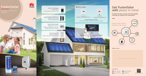
Battery Module (Energy Optimizer Included)
LUNA2000-5/10/15-S0
2.5
5
10
String Battery Solution
Power (kw)
DC Arc Fault Has Been Found the Major Cause of Fire in PV System
130GW+
Huawei inverters deployed worldwide
85% 100% 100% 100%
Higher Self-consumption
with Smart String ESS
Flexible
5kWh per pack scalable for flexible investment
Excellent product quality with extendable warranty to protect your investment
Standard 10 Years Warranty Extendable to Max. 20 Years
Available Now
FusionSolar Smart PV Management System
(Three Phase) SUN2000-3/4/5/6/8/10KTL-M1
Smart Energy Controller
Convert solar energy into electricity to power your house
Get FusionSolar with peace in mind
170+
Countries & regions with Huawei products and services
智能光伏详解
智能光伏详解
智能光伏是一种集成了先进智能技术的光伏发电系统,旨在通过实时数据采集、分析和智能控制,优化光伏能源的捕获、转换和利用效率。
其核心技术主要包括电力电子技术和数字技术,通过这些技术,智能光伏系统能够实现电站设备以及整个系统的数字化、智能化升级。
与传统光伏系统相比,智能光伏系统具有更高的能源产出稳定性和更低的运维成本。
这是因为它能够实时监测大气条件、太阳辐射强度、云量等因素,并根据这些因素的变化自动调整电站的运行状态,以最大化地利用太阳能。
此外,智能光伏系统还能够预测设备的维护需求,提前进行维护,从而避免设备故障导致的能源损失。
智能光伏系统的应用场景非常广泛,包括大型地面电站、山地丘陵、农光互补和渔光互补等各种复杂场景。
在这些场景中,智能光伏系统都能够根据具体环境条件和能源需求,提供最优的光伏发电方案。
目前,智能光伏市场正在快速发展,各大光伏企业都在积极推出自己的智能光伏解决方案。
其中,华为的FusionSolar解决方案就是一个典型的例子,它从电站的建设一直到运维,将数字信息技术、互联网等技术与光伏技术进行跨界的结合,提高了系统的发电量和运维效率。
总的来说,智能光伏是一种具有广阔应用前景和巨大市场潜力的新能源技术。
随着技术的不断进步和市场的不断扩大,智能光伏必将在未来的能源领域发挥更加重要的作用。
华为光伏逆变器说明书
华为光伏逆变器说明书1. 引言光伏逆变器作为光伏发电系统的核心设备,将太阳能电池板产生的直流电转换为交流电,供给家庭、工业和商业用电。
华为光伏逆变器以其高效稳定的性能和先进的技术而闻名于世。
本说明书旨在提供对华为光伏逆变器产品的全面介绍和详细操作步骤,以帮助用户更好地理解和使用该产品。
2. 产品概述华为光伏逆变器是一种高效、可靠的设备,用于将直流电转换成交流电。
它采用了先进的功率转换技术,具有高效率、低能耗和长寿命等特点。
华为光伏逆变器广泛应用于家庭、工业和商业领域。
2.1 主要特点•高效率:采用先进的功率转换技术,最大程度地提高能量转换效率。
•可靠性:经过严格测试和验证,确保设备在各种环境条件下运行稳定可靠。
•高度集成化:紧凑型设计,占用空间小,便于安装和维护。
•智能监控:配备智能监控系统,实时监测设备运行状态,并提供远程控制和故障诊断功能。
2.2 产品型号华为光伏逆变器提供多个型号以满足不同需求,包括家用、商用和工业级别的产品。
具体型号如下: - 家用型号:HUAWEI SUN2000-3KTL、HUAWEI SUN2000-4KTL、HUAWEI SUN2000-5KTL - 商用型号:HUAWEI SUN2000-12KTL、HUAWEI SUN2000-17KTL、HUAWEI SUN2000-20KTL - 工业型号:HUAWEI SUN2000-33KTL、HUAWEISUN2000-36KTL3. 安装与操作本章节将详细介绍华为光伏逆变器的安装和操作步骤,确保用户能正确使用该产品。
3.1 安装要求在安装华为光伏逆变器之前,请确保满足以下要求: 1. 安全接地:确保设备正确接地以防止电击。
2. 环境条件:选择合适的安装环境,避免高温、高湿度和腐蚀性气体等影响设备性能的因素。
3. 电源要求:提供稳定的电源,满足逆变器的额定输入电压和频率要求。
3.2 安装步骤1.将逆变器安装在合适位置,确保通风良好且便于维护。
华为 光伏

华为光伏在当今时代,科技和能源一直是社会关注的焦点。
华为和光伏就是其中的两个代表性例子。
华为是中国最大的科技公司之一,曾多次被评为‘全球最具创新力的公司’。
而光伏则是一种利用太阳能发电的科技,已经成为解决能源问题的重要手段。
华为和光伏如何结合在一起,为我们带来什么样的利益呢?华为是一家以研发和生产手机、通信设备、云服务等各种技术为主的公司,而在能源领域,华为是一位新手。
不过,在2018年,华为透露了一个重大消息:将进入光伏领域。
这一消息引起了业界的广泛关注。
通过不断的研究,华为成功研发出一款高效的智能光伏逆变器——华为智能光伏逆变器。
该逆变器可以将太阳能转化为电能,并且可以通过智能调节功能提高光伏发电的效率。
在此之后,华为还进一步与光伏行业展开合作。
例如在美国,华为和美国光伏公司SunPower签署了长期合作协议。
在中国境内,华为也与各大光伏企业进行了广泛合作。
华为的光伏解决方案已经在全球范围内得到了用户的广泛认可,包括来自中国、欧洲、非洲等各个国家和地区的客户。
华为抱着开放、协同的态度,致力于成为光伏行业的合作伙伴。
华为希望与光伏产业链上的各类合作伙伴携手合作,共同推动光伏行业的发展。
举个例子,华为和晶澳太阳能合作打造的“智慧光伏协同生态”解决方案,通过智能化的控制和优化,将光伏发电效率提升至新高度,同时还能对发电数据进行实时监测。
那么,华为光伏的发展对我们意味着什么呢?华为的进入,将为光伏产业带来更多的技术和资金支持,大大推动光伏产业从初级阶段向智能化、绿色化、高效化的方向发展,为全球缓解能源短缺和环境污染带来了巨大的利益。
与此同时,华为的进军,也将极大地促进电力和通信的技术融合,使得智能光伏系统更加智能化和安全性增强,为清洁能源的推广和应用创造更为优质的条件。
总的来说,华为与光伏这两个领域的相遇是一件值得关注的事情。
随着华为不断前进和光伏行业不断发展,我们相信,华为光伏将会为全球清洁能源的推广和应用创造更佳的条件,推动清洁能源产业的发展,为人类的美好未来做出更为贡献。
华为FusionSolar智能光储解决方案说明书

华为智能光伏电站智能光储解决方案华为是全球领先的ICT(信息与通信)基础设施和智能终端提供商,致力于把数字世界带入每个人、每个家庭、每个组织,构建万物互联的智能世界。
我们在通信网络、IT、智能终端和云服务等领域为客户提供有竞争力、安全可信赖的产品、解决方案与服务,与生态伙伴开放合作,持续为客户创造价值,释放个人潜能,丰富家庭生活,激发组织创新。
华为坚持围绕客户需求持续创新,加大基础研究投入,厚积薄发,推动世界进步。
2022年,华为实现销售收入6,423亿人民币。
关于华为员工总数207,000+全球最具价值品牌100强86研发人员占比55.4%全球研发投资4国家170+全球最具创新力企业8FusionSolar智能光储解决方案直流线缆交流线缆通信线缆智能子阵控制器箱变MBUS通信光伏组件&支架智能光伏控制器智能组串式储能智能储能控制器智能光伏管理系统智能电站控制器EMS/AGC/AVC箱变升压站电网接入智能子阵控制器更优投资主动构网安全可靠全面数字化SUN2000-300KTL-H0智能光伏控制器电路框图效率曲线负载率效率最大效率大于99%支持智能端子检测(SCLD)支持智能风扇除尘(SSCF)IP66防护等级支持MBUS 通信支持智能组串分断(SSLD)支持IV 检测内置交直流防雷MBUS 90%91%92%93%94%95%96%97%98%99%100%0%20%40%60%80%100%930 V 1189 V 1300 V交流浪涌保护器MPPT1MPPT2MPPT3MPPT4MPPT5DCAC输出滤波器输出EMI 滤波器MPPT6输出继电器Output Isolated RelaySUN2000-300KTL-H0技术参数效率最大效率≥ 99.03%中国效率≥ 98.53%输入最大输入电压1,500 VMPPT数量6每路MPPT最大输入电流65 A每路MPPT最大短路电流115 A每路MPPT输入组串数4/5/5/4/5/5MPPT电压范围500 V ~ 1,500 V额定输入电压1,080 V输出额定输出功率300,000 W最大视在功率330,000 VA最大有功功率(cosφ=1)330,000W额定输出电压800 V,3W + PE输出电压频率50 Hz额定输出电流216.6 A最大输出电流238.2 A功率因数0.8 超前... 0.8 滞后最大总谐波失真THD i<1%(额定工况)保护智能组串分断支持智能端子检测支持防孤岛保护支持输出过流保护支持输入反接保护支持组串故障检测支持直流浪涌保护Type II交流浪涌保护Type II绝缘阻抗检测支持残余电流监测支持显示与通信显示LED指示灯,蓝牙/WLAN+APPRS485支持USB支持MBUS支持常规参数尺寸(宽x 高x 厚)1,048 x 732 x 395 mm重量≤ 112 kg工作温度-30 ℃~ 60 ℃冷却方式智能风冷最高工作海拔5,000 m (> 4,000 m降额)相对湿度0 ~ 100%(无凝露)输入端子CT75A输出端子OT/DT端子防护等级IP66防腐等级C5-Medium拓扑无变压器满足的标准NB/T 32004-2018, GB/T 37408-2019,ISO/IEC 15408等SUN2000-196KTL-H0智能光伏控制器电路框图支持IV 检测最大效率大于99%无熔丝设计IP66防护等级18路高精度组串检测9路MPPT 支持智能组串分断内置交直流防雷效率曲线负载率效率90%91%92%93%94%95%96%97%98%99%100%0%20%40%60%80%100%1300V 1174V 1090V 1006VDC/AC 逆变电路LCL 滤波器输出继电器输入电流检测直流浪涌保护器输入EMI 滤波器SUN2000-196KTL-H0技术参数效率最大效率≥ 99.0%中国效率≥ 98.4%输入最大输入电压1,500 V每路MPPT最大输入电流30 A每路MPPT最大短路电流50 AMPPT电压范围500 V ~ 1,500 V额定输入电压1,080 V输入路数18MPPT数量9输出额定输出功率196,000 W最大视在功率216,000 VA最大有功功率(cosφ=1)216,000W额定输出电压800 V,3W + PE输出电压频率50 Hz额定输出电流141.5 A最大输出电流155.9 A功率因数0.8 超前... 0.8 滞后最大总谐波失真THD i<1%(额定工况)保护智能组串分断支持防孤岛保护支持输出过流保护支持输入反接保护支持组串故障检测支持直流浪涌保护Type II交流浪涌保护Type II绝缘阻抗检测支持残余电流监测支持显示与通信显示LED指示灯,蓝牙/WLAN+APPRS485支持USB支持MBUS支持常规参数尺寸(宽x 高x 厚)1,035 x 700 x 365 mm重量(含挂架)≤ 86 kg工作温度-25 ℃~ 60 ℃冷却方式智能风冷最高工作海拔5,000 m (> 4,000 m降额)相对湿度0 ~ 100%(无凝露)输入端子MC4 EVO2输出端子OT/DT端子防护等级IP66防腐等级C5-Medium拓扑无变压器满足的标准NB/T 32004-2018, GB/T 37408-2019,ISO/IEC 15408等LUNA2000-200KTL-H1智能储能控制器效率曲线负载率转换效率最大效率99%模块化设计IP66防护等级LUNA2000-200KTL-H1电路框图内置交直流防雷支持以太网通信Grid Forming90%91%92%93%94%95%96%97%98%99%100%0%10%20%30%40%50%60%70%80%90%100%1180V 1200V 1300V~=LUNA2000-200KTL-H1技术参数效率最大效率99.0%直流侧额定直流电压1,180 V最大直流电压1,500 V工作电压范围1,180 V ~ 1,500 V最大直流电流207.6 A最大接入路数1交流侧额定交流功率200,000 W @40°C额定交流电压800 V交流电压频率50 Hz / 60 Hz最大交流电流173.2 A功率因数-1 ... +1最大总谐波失真THD i<1%(额定工况)Grid Forming支持保护交流过流保护支持直流反接保护支持绝缘阻抗检测支持残余电流检测支持直流浪涌保护1Type II交流浪涌保护1Type II通信显示LED 指示灯,WLAN + APPUSB支持以太网支持常规参数尺寸(宽x 高x 深)875 x 820 x 365 mm重量< 99 kg工作温度-25°C~ 60°C冷却方式智能风冷最高工作海拔4,000 m相对湿度0 ~ 100%(无凝露)直流端子OT/DT端子交流端子OT/DT端子防护等级IP66防腐等级C5-Medium拓扑无变压器满足的标准GB/T 34120-2017, GB/T 34133-2017, GB/T 36547-2018, GB/T 36548-2018等1:符合IEC / EN 61643-11的兼容II类保护等级更高放电更优投资极简运维安全可靠LUNA2000-2.0MWH 系列智能组串式储能系统储能系统参数型号LUNA2000-2.0MWH-4H1LUNA2000-2.0MWH-2H1LUNA2000-2.0MWH-1H1直流侧额定电压1,250 V直流侧最大电压1,500 V储能系统电池标称能量2,032 kWh充放电倍率≤ 0.25 C≤ 0.5 C≤ 1 C 储能系统额定功率508 kW1,016 kW2,032 kW储能系统尺寸(宽x 高x 深)6,058 x 2,896 x 2,438 mm储能系统重量≤ 30 t运行温度范围-30°C~ 55°C储存温度范围-40°C~ 60°C运行湿度范围0 ~ 100%(无凝露)最高工作海拔4,000 m电池温控方式工业级空调散热系统配置 2 台 4 台 6 台储能系统火灾抑制系统全氟己酮+ 水喷淋储能系统通讯接口Ethernet / SFP储能系统通讯协议Modbus TCP / IEC 104储能系统防护等级IP55储能系统防腐等级C5-Medium满足的标准GB/T 36276-2018, GB/T 34131, UL9540A, IEC 62443-4-1, IEC 62443-4-2等智能组串式储能系统电池包& 智能电池簇控制器电池包常规参数电芯材料磷酸铁锂(LFP)组合方式18S 1P额定电压57.6 V标称容量280 Ah / 16.13 kWh 支持充放电倍率≤ 1 C重量≤ 140 kg 尺寸(宽x 高x 深)442 x 307 x 660 mm智能电池簇控制器效率最大效率99.0%电池侧额定工作电压1,209.6 V工作电压范围40 V ~ 1,400 V额定功率电压范围1,075 V ~ 1,320 V最低启动电压350 V母线侧最大直流电压1,500 V额定工作电压1,250 V额定工作电流275.2 A额定功率344,000 W常规参数尺寸(宽x 高x 深)600 x 270 x 820 mm 重量≤ 90 kg冷却方式智能风冷防护等级IP66并网点高精度直采独立双CPU智能无功补偿POD 低频振荡抑制SPPC2000 VarSPPC2000智能电站控制器技术参数SPPC2000-A01SPPC2000-A02设备管理可接入子阵数量单机支持64个(约250MW )重要特性智能无功补偿支持,基于逆变器/变流器的系统级30ms 动态无功响应POD 低频振荡抑制支持,振荡抑制范围(0.1~2.5Hz )录波功能支持电流/电压瞬时值录波(0.5ms ),支持有效值长时间录波对时功能支持IRIG-B 对时(≤1ms 精度),支持NTP 等其他协议对时辅助AGC/AVC 调节控制支持断路器状态采集和控制支持仿真模型支持PSSE, DigSILENT, PSCAD 仿真模型PT/CT 采样精度1A5A通信交互以太网口 6 + 2光纤网口SFP x 2, 100 / 1,000 MbpsRS485COM x 4并网点电流/电压采集6U + 6ICAN 2通信协议Modbus-TCP ,IEC60870-5-104,GOOSE显示LED支持WEB 支持管理系统智能光伏管理系统SmartPVMS常规参数双电源冗余供电交流:90 V ~264 V, 47 Hz ~ 63 Hz, 直流:110 V ±10%, 220 V ±10%直流/交流浪涌保护Type II尺寸(高/长/宽)1000 x 650 x 650 mm (不含底座)重量≤ 80 kg (不含栈板和选配件)工作温度-25℃~60℃工作相对湿度0%~100%(无凝露)最高工作海拔4,000 m 防护等级IP55防腐等级C5-Medium安装方式落地立式安装、壁挂安装(选配壁挂件)1:智能无功补偿&POD 低频振荡抑制,上市时间:2024.01.30SmartController (置于SPPC2000内)智能简单可靠SmartACU2000D 智能子阵控制器1:适配PLC 电力载波通信含SmartPID2000模块不含SmartPID2000模块技术参数SmartACU2000D-D-06SmartACU2000D-D-00SmartACU2000D-D-01基本配置内置数据采集器SmartLogger3000B x 1SmartModule1000A 数量选配以太网口141 或3 (配一台SmartModule1000A)或6 (配一台SmartModule1000A 和五口交换机)RS485COM x 6, 1,200 / 2,400 / 4,800 / 9,600 / 19,200 / 115,200 bps可选以太网口SFP x 10, 100 / 1,000 MbpsSFP x 2, 100 / 1,000 MbpsMBUS 接口数量¹11SmartPID2000模块数量001智能绝缘监测功能-选配环境参数工作温度-40°C ~ 60°C 工作相对湿度4% ~ 100% (无凝露)最高工作海拔4,000 m电气参数SmartACU 交流输入电压100 V ~240 V, L / N (L)+ PEMBUS 接口交流输入电压380 V ~ 800 V, 3PhPID 模块交流输入电压380 V ~ 800 V, 3Ph + FE (功能地)交流输入频率50 Hz / 60 Hz供电电源标配12 V 直流电源;选配24 V 直流电源机械参数进出线方式下进下出操作维护方式前操作、前维护尺寸(宽/高/深)640 x 770 x 315 mm880 x 770 x 369 mm重量32 kg29 kg 49 kg防护等级IP65安装方式支架、抱杆、挂墙满足的标准ROHS, IEC / EN 61000-3-2, IEC / EN 61000-3-3, EN 55011, IEC 62443-4-1, IEC 62443-4-2等智能灵活简单易用稳定可靠最多接入150台逆变器支持一键快速开局支持开局向导调测包括参数设置及设备接入工业级应用更高可靠性技术参数SmartLogger3000B SmartLogger3000B +SmartModule1000A设备管理可接入设备数量200可接入智能光伏控制器数量1150可接入智能储能控制器/智能组串式储能数量144 / 24通信交互WAN WAN x 1, 10 / 100 / 1,000 MbpsLAN LAN x 1, 10 / 100 / 1,000 MbpsLAN x 3, 10 / 100 / 1,000 Mbps光纤网口SFP x 2, 100 / 1,000 Mbps MBUS 最大交流电压800 V (±10%), 1,000 mRS485COM x 3COM x 6数字/模拟输入/输出DI x 4, DO x 2, AI x 4DI x 8, DO x 2, AI x 7PT100 / PT10002电源端口12 V, 100 mA (用于连接继电器,传感器等)防雷模块有通信协议以太网Modbus-TCP, IEC 60870-5-104RS485Modbus-RTU, IEC 60870-5-103 (标准), DL / T645显示LED LED x 3LED x 5WEB 嵌入式Web USB USB 2.0 x 1APP WLAN 连接,用于近端调试环境工作温度-40℃~ 60℃储存温度-40℃~ 70℃相对湿度5% ~ 95%(无凝露)最高海拔高度4,000 m电气参数电源适配器交流:100 V ~240 V, 50 Hz / 60 Hz, 直流:12 V, 2 A直流供电电源24 V, 0.8 A功耗典型9W ,最大15 W典型10 W ,最大18 W 机械参数尺寸(高/宽/深)225 x 160 x 44 mm 不含挂耳及天线350 x 160 x 44 mm 不含挂耳及天线重量 2 kg3 kg防护等级IP20安装方式挂墙,导轨,桌面安装满足的标准ROHS, IEC/EN 61000-3-2, IEC / EN 61000-3-3, EN 55011, IEC 62443-4-1, IEC 62443-4-2等SmartLogger3000B + SmartModule1000ASmartLogger3000B SmartLogger3000B 数据采集器1:单数采可支持接入最大数量指仅可独立接入智能光伏控制器或智能组串式储能备注:1:SmartPID 模块可应用于中压并网的电站场景,且箱变低压侧为IT系统2:SmartPID模块必须和华为智能光伏控制器/智能储能控制器和SmartLoggers 适配使用.SmartPID2000 模块内置在智能子阵控制器SmartACU2000D 内,可安全有效抑制组件PID 效应,可选支持连续直流和交流绝缘监测.智能通过USB 接口和嵌入式Web 读取数据安全可靠交流侧注入对地电压,安全抑制PID 支持连续直流和交流绝缘监测SmartPID2000 解决方案组网SmartACU2000DMBUS / RS485变压器SmartPID2000箱变接地排功能地线SmartLoggerA /B / CSmartACU2000D FE变压器智能储能控制器SmartPID2000箱变接地排功能地线SmartLoggerA /B / C智能储能控制器FE智能组串式储能智能组串式储能智能光伏控制器智能光伏控制器SmartPID2000模块智能子阵控制器组网架构SPPC2000(单机支持64个子阵~250MW )AGC/AVC远动RTU电网调度系统交换机(单环≤15个子阵)PT/CT 采集公共电网智能光伏管理系统SmartPVMS…智能光伏控制器智能组串式储能智能储能控制器……SmartACU2000光储子阵SmartACU2000光伏子阵…智能光伏控制器智能光伏控制器SmartACU2000储能子阵智能组串式储能…智能储能控制器…交换机…光纤环网*具体项目配置和销售区域详询华为工程师精细管理高效运维易用友好安全可信从电站到电芯&组串多层级、精细化管理告警分级与过滤,提供处理建议邮件推送告警信息支持快速建站电池包3D可视IEC 62443-4-1业内领先ML3等级IEC 62443-4-2业内首获SL2认证网络架构Email智能子阵控制器气象站Internet以太网专线MBUS或RS485互联网Smart PVMS智能储能控制器智能光伏控制器智能组串式储能智能光伏电站管理系统智能子阵控制器自主知识产权的操作系统、数据库支持10000等效设备接入管理专利DEMT智能功耗管理技术,优化能效出厂软件预装减少70%现场安装时间技术参数FusionServer2288X V5管理设备能力10,000等效设备形态2U机架服务器处理器2*Intel Xeon Silver 4208(2.1GHz/8-Core/11MB)内存2*32GB DDR4 RDIMM, ECC硬盘2*1.2 TB, SAS 2.5“ HDD, 10,000 RPM操作系统Euler OS数据库Gauss DBRAID方式RAID 1网络2个PCIe网络插卡,每个网络插卡支持4*GE电口电源2个热插拔900W交流电源模块,支持1+1冗余供电支持100-240 Vac/ 11 ~ 5.5 A; 240 Vdc/ 5 A;风扇支持4个热拔插对旋风扇,支持N+1冗余工作温度5°C~ 40°C尺寸(宽x高x深)86.1 x 447 x 748 mm重量29 kg认证CE、UL、FCC、CCC、RoHS等1:适配PLC电力载波通信自主知识产权的操作系统、数据库支持30000等效设备接入管理专利DEMT智能功耗管理技术,优化能效出厂软件预装减少70%现场安装时间技术参数FusionServer Pro 2288X V5管理设备能力30,000等效设备形态2U机架服务器处理器2*Intel Xeon Gold 5218(2.3GHz/16-Core/22MB)内存2*32GB DDR4 RDIMM, ECC硬盘2*1.2 TB + 8*1.8 TB, SAS 2.5” HDD, 10,000RPM操作系统Euler OS数据库Gauss DBRAID方式RAID 1, RAID 10网络2个PCIe网络插卡,每个网络插卡支持4*GE电口电源2个热插拔900W交流电源模块,支持1+1冗余供电支持100-240 Vac/ 11 ~ 5.5 A; 240 Vdc/ 5 A;风扇支持4个热拔插对旋风扇,支持N+1冗余工作温度5°C~ 40°C尺寸(宽x高x深)86.1 x 447 x 748 mm重量30 kg认证CE、UL、FCC、CCC、RoHS等1:适配PLC电力载波通信.智能IV 诊断利用AI技术对组串IV曲线进行分析,完成整个光伏电站组串的全量检测,帮助客户实现简单、高效的运维管理,降低运维投入。
华为智能光伏 FusionSolar 系列储能系统说明书
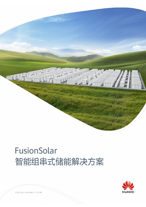
华为是全球领先的ICT (信息与通信)基础设施和智能终端提供商,致力于把数字世界带入每个人、每个家庭、每个组织,构建万物互联的智能世界。
我们在通信网络、IT 、智能终端和云服务等领域为客户提供有竞争力、安全可信赖的产品、解决方案与服务,与生态伙伴开放合作,持续为客户创造价值,释放个人潜能,丰富家庭生活,激发组织创新。
华为坚持围绕客户需求持续创新,加大基础研究投入,厚积薄发,推动世界进步。
2021年,华为实现销售收入6,368亿人民币。
关于华为员工总数195,000+国家170+研发人员107,000+财富世界500强44全球第一华为智能光伏出货量2015-2020连续六年蝉联175GW+华为智能光伏全球累计出货量更高放电一包一优化,一簇一管理提升生命周期充放电量更优配置支持新旧电池混用分期部署减少初始容量极简运维免定期容量标定节省运维成本安全可靠模块化设计储能设备高可用度智能组串式储能系统智能储能控制器FusionSolar 智能组串式储能解决方案直流配电柜智能箱变升压站电网接入智能光伏管理系统智能子阵控制器直流线缆交流线缆通讯线缆LUNA2000-2.0MWH-2H0/2H1智能组串式储能系统更高放电更优配置极简运维安全可靠储能系统参数型号LUNA2000-2.0MWH-2H0LUNA2000-2.0MWH-2H1直流侧额定电压1,200 V1,250 V直流侧最大电压1,500 V1,500 V储能系统电池标称能量2,064 kWh2,032 kWh储能系统额定功率(0.5C)344 kW * 3338.7 kW * 3储能系统额定功率(1C)344 kW * 6338.7 kW * 6储能系统尺寸(宽x 高x 深)6,058 x 2,896 x 2,438 mm6,058 x 2,896 x 2,438 mm 储能系统重量≤ 30 t≤ 30 t运行温度范围-30°C~ 55°C-30°C~ 55°C储存温度范围-40°C~ 60°C-40°C~ 60°C运行湿度范围0 ~ 100%(无凝露)0 ~ 100%(无凝露)最高工作海拔4,000 m4,000 m电池温控方式工业级空调工业级空调空调配置 6 台 6 台储能系统火灾抑制系统FM-200FM-200储能系统通讯接口Ethernet / SFP Ethernet / SFP 储能系统通讯协议Modbus TCP / IEC 104Modbus TCP / IEC 104储能系统防护等级IP55IP55满足的标准认证GB/T 36276-2018, GB/T 34131, UN 3536等LUNA2000-4.0MWH-2H1智能组串式储能系统更高放电更优配置极简运维安全可靠储能系统参数直流侧额定电压1,250 V直流侧最大电压1,500 V储能系统电池标称能量4,064 kWh储能系统额定功率(0.5C)338.7 kW * 6储能系统尺寸(宽x 高x 深)12,192 x 2,896 x 2,438 mm储能系统重量≤ 60 t运行温度范围-30°C~ 55°C储存温度范围-40°C~ 60°C运行湿度范围0 ~ 100%(无凝露)最高工作海拔4,000 m电池温控方式工业级空调空调配置12 台储能系统火灾抑制系统FM-200储能系统通讯接口Ethernet / SFP储能系统通讯协议Modbus TCP / IEC 104储能系统防护等级IP55满足的标准认证GB/T 36276-2018, GB/T 34131, UN 3536等智能组串式储能系统电池包& 智能电池簇控制器电池包常规参数型号LUNA2000-2.0MWH-2H0LUNA2000-2.0MWH-2H1 LUNA2000-4.0MWH-2H1电芯材料磷酸铁锂(LFP)磷酸铁锂(LFP)组合方式16S 1P18S 1P额定电压51.2 V57.6 V标称容量320 Ah / 16.38 kWh280 Ah / 16.13 kWh 支持充放电倍率≤ 1 C≤ 1 C重量≤ 140 kg≤ 140 kg尺寸(宽x 高x 深)442 x 307 x 660 mm442 x 307 x 660 mm智能电池簇控制器效率型号LUNA2000-2.0MWH-2H0LUNA2000-2.0MWH-2H1 LUNA2000-4.0MWH-2H1最大效率99.0%99.0%电池侧额定工作电压1,075.2 V1,209.6 V工作电压范围40 V ~ 1,400 V40 V ~ 1,400 V额定功率电压范围1,075 V ~ 1,320 V1,075 V ~ 1,320 V 最低启动电压350 V350 V母线侧最大直流电压1,500 V1,500 V额定工作电压1,200 V1,250 V额定工作电流286.7 A275.2 A额定功率344,000 W344,000 W常规参数尺寸(宽x 高x 深)600 x 270 x 820 mm600 x 270 x 820 mm 重量≤ 90 kg≤ 90 kg冷却方式智能风冷智能风冷防护等级IP66IP66LUNA2000-200KTL-H0智能储能控制器效率曲线90%91%92%93%94%95%96%97%98%99%100%0%10%20%30%40%50%60%70%80%90%100%1180V 1200V 1300V负载率转换效率最大效率99%模块化设计IP66防护等级LUNA2000-200KTL-H0电路框图~=内置交直流防雷支持以太网通信智能并网算法1:满足GB/T 34120要求2:符合IEC / EN 61643-11的兼容II类保护等级LUNA2000-200KTL-H0技术参数效率最大效率99.0%直流侧额定直流电压1,180 V最大直流电压1,500 V工作电压范围1,180 V ~ 1,500 V最大直流电流207.6 A最大接入路数1交流侧额定交流功率200,000 W @40°C最大视在功率1240,000 VA最大有功功率1(cosφ=1)240,000W额定交流电压800 V交流电压频率50 Hz / 60 Hz最大交流电流173.2 A功率因数-1 ... +1最大总谐波失真<3%保护防孤岛保护支持交流过流保护支持直流反接保护支持绝缘阻抗检测支持残余电流检测支持直流浪涌保护2Type II交流浪涌保护2Type II通信显示LED 指示灯,WLAN + APP USB支持以太网支持常规参数尺寸(宽x 高x 深)875 x 820 x 365 mm重量< 95 kg工作温度-25°C~ 60°C冷却方式智能风冷最高工作海拔4,000 m相对湿度0 ~ 100%直流端子OT/DT端子交流端子OT/DT端子防护等级IP66拓扑无变压器DCBOX-9/5-H0直流配电柜电气参数最大输入电压1,500 V额定输入电压1,200 V智能电池簇控制器侧最大支路电流321 A智能储能控制器侧最大支路电流193 A直流断路器数量14智能电池簇控制器最大可接入数量9智能储能控制器最大可接入数量5最大汇流能力 5 x 193 A保护直流过流保护支持环境参数工作温度-30°C~ 60°C (40°C 以上降额)工作相对湿度0 ~ 100%最高工作海拔4,000 m常规参数进出线方式储能控制器支路上进线,电池簇控制器支路下进线尺寸(宽x 高x 深)2,040 x 1,415 x 975 mm重量(不含智能储能控制器)≤ 750 kg输入输出端子OT端子防护等级IP55安装方式落地智能简单可靠SmartACU2000D 智能子阵控制器技术参数SmartACU2000D-D-00基本配置内置数据采集器内置SmartLogger3000Bx 1内置扩展模块支持选配SmartModule1000ARS485标配MBUS 接口数量11路环境参数工作温度-40°C ~ 60°C 工作相对湿度4% ~ 100%最高工作海拔4,000 m电气参数SmartACU 交流输入电压100 V ~240 V, L / N (L)+ PEMBUS 接口交流输入电压380 V ~ 800 V, 3Ph PID 模块交流输入电压380 V ~ 800 V, 3Ph+FE (功能地)交流输入频率50 / 60 Hz 供电电源标配12 V 直流电源选配24 V 直流电源机械参数进出线方式下进下出操作维护方式前操作、前维护尺寸(宽x 高x 深)640 x 770 x 315 mm重量29 kg 防护等级IP65安装方式支架、抱杆、挂墙1. 适配PLC 电力载波通信.智能光伏管理系统Smart PVMS网络架构Smart PVMSWebEmailSmartLogger SUN2000SUN2000气象站InternetInternetSmartLoggerSUN2000SUN2000气象站IE专线MBUS 或RS485互联网智能简单可靠收益与告警主动上报支持智能IV 曲线诊断PC 端一键安装支持邮件主动推送告警所有站点一屏管理数据最长保存25年自主知识产权的操作系统、数据库支持10000等效设备接入管理专利DEMT智能功耗管理技术,优化能效出厂软件预装减少70%现场安装时间技术参数FusionServer2288X V5管理设备能力10,000等效设备形态2U机架服务器处理器2*Intel Xeon Silver 4208(2.1GHz/8-Core/11MB)内存2*32GB DDR4 RDIMM, ECC硬盘2*1.2 TB, SAS 2.5“ HDD, 10,000 RPM操作系统Euler OS数据库Gauss DBRAID方式RAID 1网络2个PCIe网络插卡,每个网络插卡支持4*GE电口电源2个热插拔900W交流电源模块,支持1+1冗余供电支持100-240 Vac / 11 ~ 5.5 A; 240 Vdc / 5 A;风扇支持4个热拔插对旋风扇,支持N+1冗余工作温度5°C~ 40°C尺寸(宽x高x深)86.1 x447 x748 mm 重量29 kg认证CE、UL、FCC、CCC、RoHS等自主知识产权的操作系统、数据库支持30000等效设备接入管理专利DEMT智能功耗管理技术,优化能效出厂软件预装减少90%现场安装时间技术参数FusionServer Pro 2288X V5管理设备能力30,000等效设备形态2U机架服务器处理器2*Intel Xeon Gold 5218(2.3GHz/16-Core/22MB)内存2*32GB DDR4 RDIMM, ECC硬盘2*1.2 TB + 8*1.8 TB, SAS 2.5” HDD, 10,000RPM操作系统Euler OS数据库Gauss DBRAID方式RAID 1, RAID 10网络2个PCIe网络插卡,每个网络插卡支持4*GE电口电源2个热插拔900W交流电源模块,支持1+1冗余供电支持100-240 Vac / 11 ~ 5.5 A; 240 Vdc/ 5 A;风扇支持4个热拔插对旋风扇,支持N+1冗余工作温度5°C~ 40°C尺寸(宽x高x深)86.1 x447 x748 mm 重量30 kg认证CE、UL、FCC、CCC、RoHS等版权所有©华为技术有限公司2022。
华为太阳能技术有限公司SUN2000系列快速引导书说明书

SUN2000-(20KTL, 29.9KTL, 30KTL, 36KTL, 40KTL)-M3Quick GuideIssue: 01Part Number: 31500EACDate: 2020-10-15HUAWEI TECHNOLOGIES CO., LTD.1Overview•The information in this document is subject to change without notice. Every effort has been made in the preparation of this document to ensure accuracy of the contents, but all statements, information, and recommendations in this document do not constitute a warranty of any kind, express or implied.•Only qualified and trained electrical technicians are allowed to operate the device. Operation personnel should understand the composition and working principles of the grid-tied PV power system and local regulations.•Before installing the device, read the user manual carefully to get familiar with productinformation and safety precautions. Huawei shall not be liable for any consequences caused by the violation of the storage, transportation, installation, and operation regulations specified in this document and the user manual.•Use insulated tools when installing the device. For personal safety, wear proper personal protective equipment (PPE).(1) LED indicators (2) Host panel(3) Heat sink(4) Screws for fixing the awning (5) Communications port (COM)(6) Hole for the DC switch locking screw (7) DC switch (DC SWITCH)(8) Smart Dongle port (4G/WLAN-FE)(9) Ventilation valves (10) DC input terminals (PV1–PV8)(11) AC output port(12) Ground point2Installation RequirementsAngle SpaceDimensions3Installing a Solar Inverter•M12x40 bolt assemblies are supplied with the solar inverter. If the bolt length does not meet the installation requirements, prepare M12 bolt assemblies by yourself and use themtogether with the supplied M12 nuts.•This quick guide describes how to install a solar inverter on a support. For details about wall-mounted installation, see the user manual.•For models used in Australia, install the DC switch locking screw according to local standards.The DC switch locking screw is delivered with the solar inverter to prevent the solar inverter from being started by mistake.•Before installing the mounting bracket, remove the security Torx wrench and set it aside.Position for binding the security Torxwrench1.Install the mounting bracket.Moving the Solar InverterIt is recommended that anti-rust measures be taken on the positions for drilling holes.(Optional) Installing the DCSwitch Locking Screw2.Install the solar inverter onto themounting bracket. 3.Tighten the security Torx screws on bothsides.Preparations4.14Connecting Cables•Connect cables in accordance with local installation laws and regulations.•The cable specifications must comply with local standards.•Before connecting cables, ensure that the DC switch of the solar inverter and all the switches connected to it are set to OFF. Otherwise, the high voltage produced by the solar inverter may cause electric shocks.No.Cable TypeSpecifications1PE cableSingle-core outdoor copper-core cableConductor cross-sectional area ≥ 16 mm 22AC output power cable Outdoor copper-core/aluminum-core cable•Conductor cross-sectional area: 16-50mm 2outdoor copper-core cable or 35-50 mm 2outdoor aluminum-core cable •Cable outer diameter: 16–38 mm 3DC input power cableCommon outdoor PV cable in the industry (recommendedmodel: PV1-F)•Conductor cross-sectional area: 4–6 mm 2•Cable outer diameter: 5.5–9 mm 4(Optional) RS485 communications cable Two-core outdoor shielded twisted pair (recommended model: DJYP2VP2-2x2x0.75)•Conductor cross-sectional area: 0.2–1 mm 2•Cable outer diameter: 4–11 mmNote a: Five-core cables with a cross-sectional area of 5 x 35 mm 2or 5 x 50 mm 2are not supported.Secure the screws on the sides before connecting cables.Connecting a PE Cable4.2•The PE point at the AC output port is used only as a PE equipotential point, not a substitute for the PE point on the enclosure.•It is recommended that silica gel or paint be applied around the ground terminal after the PE cable is connected.Do not connect the neutral wire to the enclosure as a PE cable. Otherwise, electric shocks may occur.Installing the AC Output Power Cable4.3•Use a socket wrench and extension rod to connect the AC power cable. The extension rod must be longer than 100 mm.•Sufficient slack should be provided in the PE cable to ensure that the last cable bearing the force is the PE cable when the AC output power cable bears pulling force due to force majeure.•Do not install third-party devices in the AC connection box.•You need to prepare M8 OT terminals by yourself.1.Remove the AC terminal box and install partition boards.Reserved PE point2.Connect the AC output power cable (using a five-core cable as an example).•To avoid damaging the rubber liner, do not route a cable with a crimped OT terminal directly through it.•It is recommended that the length of the PE cable to be stripped be 15 mm longer than the length of other cables.•The cable colors in figures are for reference only. Select appropriate cables according to the local standards.e the positive and negative Staubli MC4 metal terminals and DC connectors supplied with the solar inverter. Using incompatible positive and negative metal terminals and DCconnectors may result in serious consequences. The caused device damage is not covered under any warranty.2.You are advised to use the PV-CZM-22100 (Staubli) crimping tool and do not use it with the positioning block. Otherwise, the metal terminals may be damaged. The PV-MS (Staubli) or PV-MS-HZ (Staubli) open-end wrench is recommended.3.Ensure that the PV module output is well insulated to ground.4.The DC input voltage of the SUN2000-29.9KTL/30KTL/36KTL/40KTL-M3 shall not exceed 1100 V DC under any circumstance.5.The DC input voltage of the SUN2000-20KTL-M3 shall not exceed 800 V DC under any circumstance.6.Before installing DC input power cables, label the cable polarities to ensure correct cable connections.7.If a DC input power cable is reversely connected and the DC switch is turned on, do not operate on the DC switch or the positive/negative connectors immediately. Otherwise, the device may be damaged. The caused device damage is not covered under any warranty. Wait until the night when solar irradiance declines and the PV string current drops to below 0.5 A. Then set the DC switch to the OFF position, remove the positive and negative connectors, and correct the polarity of the DC input power cable.Installing DC Input Power Cables4.41.Connect the DC power cables.Positive connectorNegative connectorPositive metal terminalNegative metal terminalEnsure that the cable cannot be pulled out after being crimped.ClickClickPV-CZM-22100PV-MS-HZ Open-end wrenchEnsure that the cables are correctly connected.Use the wrenchshown in the figure to tighten the locking nut. When the wrench slips during the tightening, thelocking nut has been tightened.4.5(Optional) Installing the Smart Dongle•The Smart Dongle is not provided in standard configuration.•If your Smart Dongle is a WLAN Smart Dongle or is configured with a SIM card, skip this step. The configured SIM card can be used only on the Smart Dongle. The SIM card is aChina Mobile card. Before installation, check whether the site is effectively covered by China Mobile signals. If not, prepare a SIM card of other carriers.•If your Smart Dongle is not equipped with a SIM card, prepare a standard SIM card (size: 25 mm x 15 mm) with the capacity greater than or equal to 64 KB.•When installing the SIM card, determine its installation direction based on the silk screen and arrow on the card slot.•Press the SIM card in place to lock it, indicating that the SIM card is correctly installed.•When removing the SIM card, push it inwards to eject it.Smart Dongle port (4G/WLAN-FE)WLAN-FE4G•For details about how to operate the WLAN-FE Smart Dongle SDongleA-05, see SDongleA-05 Quick Guide (WLAN-FE).•For details about how to operate the 4G Smart Dongle SDongleA-03, see SDongleA-03 Quick Guide (4G).The quick guide is delivered with the Smart Dongle or can be obtained by scanning the QR codes.4G Smart DongleWhen reinstalling the cover of the Smart Dongle,ensure that the buckle springs back in place.WLAN-FE Smart Dongle (WLAN Communication)WLAN-FE Smart Dongle (FE Communication)Install the network cable before installing the Smart Dongle on the solar inverter.Installing the Signal Cable4.6•When laying out the signal cable, separate it from the power cable and keep it away from strong interference sources to avoid strong communication interference.•Ensure that the protective layer of the cable is inside the connector, that excess core wires are cut off from the protection layer, that the exposed core wire is totally inserted into the cable hole, and that the cable is connected securely.COM Port Pin DefinitionsNo.Definition Function Description No.Definition Function Description1485A1-1RS485differentialsignal +Used for invertercascading orconnecting tothe RS485 signalport on theSmartLogger2485A1-2RS485differentialsignal +Used forinvertercascading orconnecting tothe RS485 signalport on theSmartLogger3485B1-1RS485differentialsignal –4485B1-2RS485differentialsignal –5PE Ground pointon the shieldlayer–6PEGroundpoint on theshield layer–7485A2RS485differentialsignal +Connects to theRS485 signalport on thepower gridschedulingpower meter.8DIN1Dry contactfor powergridscheduling–9485B2RS485differentialsignal –10DIN211–––12DIN3 13GND GND–14DIN415DIN5Rapidshutdown Supports AC NS protectionshutdown, whichcan be used as areserved port forrapid shutdownsignals.16GNDScenarios Where No Signal Cable Is ConnectedIf no signal cable is required for the SUN2000, use waterproof plugs to block the wiring holes on the signal cable connector and connect the signal cable connector to the communications port on the SUN2000 to improve the waterproof performance of the SUN2000.(Optional) Connecting the Signal Cable1.Connect the signal cable to the signal connector.•Connect the RS485 communications cable to the solar inverter.If two or more solar inverters are cascaded, install the RS485 communications cable.•Connect the RS485 communications cable to the power meter.•Connect the power grid scheduling signal cable.•Connect the rapid shutdown signal cable.2.Connect the signal cable connector to the communications port.Communicationsport (COM)5Verifying the InstallationNo.Acceptance Criteria1The solar inverter is installed correctly and securely.2The cables are routed properly as required by the customer.3The communications expansion module is installed correctly and securely.4Cable ties are evenly distributed and no burr exists.5The PE cable is connected correctly and securely.6The DC switch and all the switches connected to the solar inverter are set to the OFF position.7The AC output power cable, DC input power cables, and signal cable are connected correctly and securely.8Unused terminals and ports are locked by watertight caps.9The installation space is proper, and the installation environment is clean and tidy.6System Power-OnBefore turning on the AC switch between the solar inverter and the power grid, check that the AC voltage is within the specified range using a multimeter set to the AC position.1.Turn on the AC switch between the solar inverter and the power grid.2.(Optional) Remove the locking screw beside the DC switch. Store the screws properly forfuture power-off maintenance.3.Turn on the DC switch at the bottom of the solar inverter.4.Observe the LED indicators to check the operating status of the solar inverter.Category Status(Blinking Slowly: On for 1s and thenOff for 1s; Blinking Fast: On for 0.2s andthen Off for 0.2s)DescriptionRunning indicator–Steady green Steady green The solar inverter is operating ingrid-tied mode.Blinking greenslowly Off The DC is on and the AC is off. Blinking greenslowly Blinking green slowlyBoth the DC and AC are on, andthe solar inverter is not supplyingpower to the power grid.Off Blinking green slowly The DC is off and the AC is on. Off Off Both the DC and AC are off. Blinking red fast–DC environment alarm–Blinking red fast AC environment alarmSteady red Steady red FaultCommunications indicator–Blinking green fast Communication is in progress. Blinking green slowly Mobile phone accessOff No communicationNote: If LED1, LED2, and LED3 are steady red, the solar inverter is faulty and needs to be replaced.7System Commissioning•If the solar inverter is connected to the FusionSolar smart PV management system, the FusionSolar app is recommended. If the solar inverter is connected to other management systems, the SUN2000 app is recommended.•Access the Huawei app store (), search for FusionSolar or SUN2000, and download the app installation package. You can also scan the QR codes below to download the apps.FusionSolar App (Android)SUN2000 App (Android)•The latest Android version must be used for device commissioning. The iOS version is not updated and can be used only for viewing PV plant information.•The screenshots are for reference only. The actual screens prevail.•Obtain the initial password for connecting to the solar inverter WLAN from the label on the side of the solar inverter.•Set the password at the first login. To ensure account security, change the password periodically and keep the new password in mind. Not changing the password may cause password disclosure. A password left unchanged for a long period of time may be stolen or cracked. If a password is lost, devices cannot be accessed. In these cases, the user is liable for any loss caused to the PV plant.•Set the correct grid code based on the application area and scenario of the solar inverter.•Create the first installer account will generate a domain named after the company.If you already have an installer account, skip this step.•To create multiple installer accounts for a company, log in to the FusionSolar app and tap New User to create installer accounts.1.(Optional) Register an installer account.Scenario in Which Solar Inverters Are Connected to the FusionSolarSmart PV Management System7.12.Create a PV plant and a plant owner.1.Open the SUN2000 app, scan the QR code of the solar inverter or manually connect to the WLAN hotspot to access the device commissioning screen.2.Select installer and enter the login password.3.Tap Log in to access the quick settings screen or solar inverter home screen.Scenario in Which Solar Inverters Are Connected to Other Management Systems7.2For details about the operations of the SUN2000 app and FusionSolar app, see the FusionSolar App Quick Guide . You can download the reference by scanning the QR code on the right.Inverter Connected to Optimizers7.3For details about how to add optimizers and the physical layout of optimizers, see SUN2000-450W-P Smart PV Optimizer Quick Guide and FusionSolar App Quick Guide . You can scan the QR codes to obtain the documents.8FAQ: How Do I Reset the Password?1.Check that the AC and DC power supplies to the solar inverter are connected simultaneously, and that the and indicators are steady green or blink slowly for more than 3 minutes.2.Turn off the AC switch, set the DC switch at the bottom of the solar inverter to OFF, and wait until all indicators on the solar inverter panel turn off.plete the following operations within 3 minutes:a.Turn on the AC switch and wait until the indicator blinks.b.Turn off the AC switch and wait until all indicators on the solar inverter panel turn off.c.Turn on the AC switch and wait until all LED indicators on the inverter panel blink and turn off after about 30s.a.Wait until the indicator blinks.b.Obtain the initial WLAN hotspot name (SSID) and initial password (PSW) from the label on the side of the solar inverter to connect to the app.c.On the login page, set a new login password and log in to the app.6.Set router and management system parameters to implement remote management.You are advised to reset the password in the morning or at night when the solar irradiance is low.4.Wait until the three indicators on the inverter panel blink green quickly and then blink red quickly, indicating that the password has been restored.5.Reset the password within 10 minutes. (If no operation is performed within 10 minutes, all parameters of the solar inverter remain the same as those before the reset.)SUN2000-450W-P FusionSolar APPHuawei Technologies Co., Ltd. Huawei Industrial Base, Bantian, Longgang Shenzhen 518129 People's Republic of China。
华为智能光伏解决方案

以我给的标题写文档,最低1503字,要求以Markdown 文本格式输出,不要带图片,标题为:华为智能光伏解决方案# 华为智能光伏解决方案## 1. 简介光伏发电作为一种清洁能源形式,受到了越来越多国家的关注和推广。
然而,传统的光伏发电系统在运维效率、智能化程度以及运营成本等方面存在一定的局限性。
为了克服这些问题,华为推出了智能光伏解决方案,通过技术创新和数字化转型,提升了光伏发电系统的效能与智能化程度。
## 2. 解决方案的架构华为智能光伏解决方案采用了分布式架构,核心组成部分包括智能逆变器、智能监控平台和智能电表。
这些组件通过通信网络相互连接,形成一个完整的智能光伏发电系统。
### 2.1 智能逆变器智能逆变器是华为智能光伏解决方案的关键组件之一,它负责将太阳能电池板产生的直流电转换成交流电,并输出到电网中。
相比于传统的逆变器,华为的智能逆变器采用了先进的数字控制技术和高效率的瞬态响应算法,以降低系统能量损失,并提供更加稳定和可靠的电力输出。
### 2.2 智能监控平台智能监控平台是华为智能光伏解决方案中的核心管理系统,通过实时监测和分析光伏发电系统的运行状态,提供数据分析和决策支持。
该平台具备以下功能:- 实时监控:通过与智能逆变器和智能电表的连接,实时采集和显示光伏发电系统的运行数据,包括功率、电压和频率等。
- 远程控制:通过互联网连接,管理员工可以远程监控和控制光伏发电系统,对问题进行即时处理,提高系统的运维效率。
- 数据分析:智能监控平台拥有强大的数据分析功能,能够对光伏发电系统运行数据进行深度挖掘,发现潜在问题和优化机会。
- 报警和预警:智能监控平台可设置各种报警和预警机制,当光伏发电系统出现故障或异常情况时,及时发送通知,并提供相应的解决方案。
### 2.3 智能电表智能电表是智能光伏解决方案的另一个重要组成部分,它用于精确测量光伏发电系统输出的电能,并与智能监控平台实现即时数据共享。
华为太阳能逆变器SUN2000产品质保与服务条款说明书

HUAWEI SUN2000 Inverter Warranty and Service Conditions For French Polynesiaand New CaledoniaHuawei Technologies (New Zealand) Company LimitedHuawei Solar InverterWarranty and Service ConditionsThese warranty and service conditions apply to the following products:➢SUN2000-3/5/6 KTL-L1➢SUN2000-5/6/10KTL-M1➢SUN 2000-100KTL-M1➢SUN2000-8/10/12/15/17/20KTL-M2➢SUN2000-115KTL-M2➢SUN2000-29.9/30/36/40/50KTL –M3➢SUN2000-450/600W-P➢SUN2000-450W-P2➢Smart Dongle, Smartlogger and Smart ACU➢Smart Power Sensor➢LUNA2000-5/10/15-S0➢Backup Box-B0/B1The Warranties described in this document are subject to any rights you may have under local consumer laws.Warranty period:2.1 Warranty Specification for Smart String inverter and Auxiliary ProductWarranty PeriodProduct Warranty Commencement Warranty PeriodSUN2000 Series Products(Except M3)Warranty commences from the180th day from the date of theproduct shipment from HuaweiFactory, or the installation date,whichever is earlier.Warranty commences from the180th day from the date of theproduct shipment from HuaweiFactory, or the installation date,whichever is earlier.120 months(1st - 10th year) Spare device, LogisticSUN2000-M3 SeriesProducts60 months(1st - 5th year) Spare device, LogisticSmart Dongle, Smartlogger and SmartACU24 months Spare device, LogisticSUN2000-450/600W-P SUN2000-450W-P2 Smart PV Optimizer300 months Spare device and logisticSmart Power Sensor24 months Spare device, LogisticBackup Box 24 monthsSpare device, Logistic 2.2 Warranty Specification for Smart String BatteryProduct WarrantyPeriod Life Cycle Power During Warranty Period(Only for 5kWh battery pack)WarrantyExtensionLUNA2000 10 years 16.45MWh@60% EOL Not Applicable Notices:1.Battery warranty is defined as when the battery pack reaches the warranty period or the lifecycle discharge is completed, the remaining capacity EOL meets the specification requirements, and the first comes into effect; the power module DCDC only involves the warranty period and has nothing to do with the battery performance. The battery pack and power module provide independent warranty.2.Capacity test conditions: at an ambient temperature of 25°C±3°C, after charging to 100% SOC,let it stand for 10 minutes, and discharge the tested battery cell at a set current of 0.2C to the discharge termination voltage, and record the amount of electricity released in the process.3.In order to remotely upgrade the latest firmware to ensure battery life, the battery is highlyrecommended to connect to the Huawei FusionSolar SmartPV management system.4.After the battery is purchased, the installation needs to be completed within one month. If thebattery fails, it needs to be reported within two weeks. The battery cell damage caused by the negligence of battery that cannot be charged for a long time is not covered by the warranty. 5.The operation and service life of battery are related to the working temperature. Please installthe battery at a temperature equal to or better than the ambient temperature. Therecommended working temperature for battery is 15~30℃.Warranty period:3.1 Huawei provides remote support and hardware support for solar inverterWarranty ServiceServiceServiceClassificationService Content AvailabilityRemote SupportRemote TechnicalSupportE-mail: ******************************Online TechnicalSupporthttps:///services/HardwareSupportHardware Support(Exclude LUNA2000)5 Business days-shipment*Hardware Support(LUNA2000)30 Calendar days-shipment**Huawei will use commercially reasonable efforts to ship a replacement device (LUNA excluded) within five business days after an RMA is issued, and to ship a replacement LUNA within thirty Calendar days after an RMA is issued. Actual delivery times may vary depending on distributor location.➢Remote SupportRemote Support means Huawei provides solutions for technical enquiries or problems relating to the solar inverter products under warranty by telephone or e-mail. It includes Help Desk, Remote Technical support and Online Technical Support (https:///services/).•Remote Technical Support provides technical support to Huawei’s customers for solar inverter products, these includes technical enquiry, problem handling, and firmware update.The technical enquiry service provides consultation services in respect of Huawei inverterproducts. And when we do the maintenance of the FusionSolar, Huawei may update orrestart your system. Email:******************************➢Hardware SupportDuring the applicable Warranty Period, Huawei guarantees that all solar inverter hardware, Smart PV Optimizer, Smart Power Sensor, Smart Dongle, Smartlogger, SmartACU, Backup Box and LUNA2000 purchased shall be free from defects in material, fabrication and workmanship.•Solar inverter, Smart PV Optimizer, Smart Power Sensor, Smart Dongle, Smartlogger, SmartACU, Backup Box and LUNA2000 that are defective in material, fabrication orworkmanship or do not meet the published specifications shall be replaced free of charge.•For solar inverters, Smart PV Optimizer, Smart Power Sensor, Smart Dongle, Smartlogger, SmartACU, Backup Box during the Warranty Period, Huawei will send the replacementdevice to the customer within 5 Business Days after device fault being confirmed. ForLUNA2000 products, Huawei will send the replacement device to the customer within 30calendar days after RMA is confirmed. After receiving the replacement device, customermust return the defective device (packed in the packaging from the replacement device)within 15 Business Days of receipt of the replacement device and Huawei will cover the cost of postage. Defective devices not returned in time for any reason may be charged tocustomer.•The replacement device provided by Huawei will be functionally equivalent to the customer’s defective device (in features, functions, compatibility, provided with defaultsoftware version).•The replacement device provided by Huawei will be covered by the remainder of the original device warranty period.Disclaimer:➢All above mentioned warranty and support services apply only to SUN2000 Series Products, Smart PV Optimizer, Smart Power Sensor, Smart Dongle, SmartLogger, SmartACU, andLUNA2000.➢Subject to any rights you may have under local consumer laws, accessories and consumable parts, including but not limited to cables and connectors, are not covered by the warranties and services set out above.➢If Huawei cannot fulfil its service commitments within the committed time period due to non-Huawei causes, Huawei shall not be liable for the failure to meet the SLA commitments. If on-site service is required, traveling time is excluded from the SLA time.➢Warranties and services shall not apply in the following circumstances:•Damage as a result of force majeure (including but not limited to natural disasters, fires and war).•Damage as a result of natural wear and tear.•Direct damage caused by failure to meet system requirements provided in writing including site running environment or external electricity parameters.•Damage from lightning due to unsuitable system design.•Damage to hardware or data due to customer’s negligence, inappropriate operation or intentional damage.•Damage caused by non-compliance with the operation manual of the equipment.•System damage caused by the customer or third parties, including relocation and installation of the system not in compliance with Huawei’s requirements or instructions.•Damage caused by adjustment, change or removal of identification marks not in compliance with Huawei requirements or instructions•System damage directly caused by problems in customer’s infrastructure.Huawei Service OrganizationHuawei has built up an extensive service organization world-wide. We are serving our customers with warranty services and spare parts for a wide range of technologies. For support of the warranty services for SUN2000 products, Huawei has defined a support organization to support the process as depicted below:Contact DetailsHuawei Technologies (New Zealand) Company LimitedLevel 23, The Huawei Centre, 120 Albert Street, Auckland, New ZealandE-mail: ******************************Web: https:///。
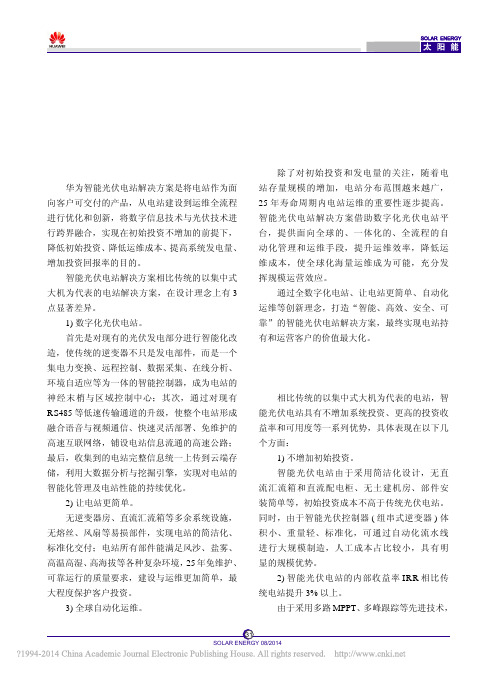
华为FusionSolar智能光伏电站解决方案技术白皮书
持平
持平
高 3%
低
平均高 5%
一般不高于 80%
25 年的系统可靠运行免维护设计
逆变器等关键部件 5 ~ 10 年需全部更换
分布式并联系统。故障次数少 30%,系统
故障对发电量的影响只有传统方案的 1/10,
串联系统,系统可用度低
质保期外的维护成本只有传统方案的 1/5
组串级监控,精度大于 0.5% 多路 MPPT,
等环境破坏;电磁辐射小,保护人体健康。智 能光伏电站实现了人与环境和谐共处,大幅增
通过数据实时采集、云存储和在线专家分析 加了光伏电站的适用范围,为光伏入户创造了
系统,电站可自动体检,给出基于收益最大化的 条件。
维护建议,如清洗建议、部件更换和维护建议等,
实现预防性维护;积累长期运营数据,综合分析 3 智能光伏电站解决方案与传统光伏电站
管理和运维手段
管理系统
云存储为基础,大数据挖掘和专家分析
系统支撑的开放平台,用户可自定义报
传统 CS 架构,封闭的管理系统
表和二次开发
无风扇,29 dB 的低环境噪声;
一般噪声大于 50 dB 以上;需土建基础;
无需土建基础;电磁辐射小
电磁辐射高
33 SOLAR ENERGY 08/2014
主动安全,减少直流线缆长度,去除直流 被动安全,直流传输距离长,有熔丝等
汇流等,主动规避直流传输带来的安全和 易损部件,在复杂光照条件和屋顶环境
防护问题
存在着火等安全隐患
电池板负极无需接地,安全规避 PID 效应 电池板负极需接地,存在安全隐患
提供面向全球、一体化、全流程的自动化
面向电站的、以监控为主的单电站
3) 25 年的系统可靠运行免维护设计。 智能控制器采用 IP65 防护等级,实现内部 和外部的环境隔离,使器件保持在稳定的运行 环境中,降低温度、风沙、盐雾等外部环境对 器件寿命的影响;系统无易损部件,无熔丝、 风扇等需定期更换器件,实现系统免维护;借 鉴华为通信基站产品全球海量发货及部署的设 计和质量管理经验,从器件到系统实现 25 年可 靠性设计及寿命仿真;加上严格的验证测试, 保证系统部件在整个生命周期内无需更换,可 靠、经济运行。 4) 光伏电站装机容量的实际利用率高。 智能光伏电站年平均故障次数比传统集中式 方案少 30%,系统故障对发电量的影响只有传统 方案的 1/10,质保期外的维护成本只有传统方案 的 1/5。传统的光伏电站本质上是一个串联系统, 直流汇流箱、直流配电柜、机房散热及辅助源供 电设备、逆变器大机等任何一个部件的故障均会 造成部分或全部光伏阵列发电损失,由于需要专 业人员维护,修复周期长、成本高。而智能光伏 电站结构简单,本质上是一个分布式的并联系统, 单台逆变器的故障不影响其他设备运行,而且由 于体积小、重量轻、现场整机备件,易安装维护, 大幅提升了系统的可用度。 5) 组串级的智能监控及多路 MPPT 跟踪技 术,确保电站“可视、可信、可管、可控”。 智能光伏电站对输入的每一路组串进行独立 的电压电流检测,检测精度是传统智能汇流箱方 案的 10 倍以上,为准确定位组串故障、提高运 维效率奠定了基础。多路 MPPT 技术,降低遮挡、 灰尘、组串失配的影响,平坦地形下发电量提升 5% 以上;在屋顶、山地电站中降低不同朝向、
华为300kw逆变器参数

华为300kw逆变器参数华为300kW逆变器参数华为是一家全球领先的信息技术解决方案提供商,其产品涵盖电信网络、IT、智能终端和云服务等领域。
在可再生能源领域,华为也推出了一系列逆变器产品,其中包括300kW逆变器。
本文将从多个方面介绍华为300kW逆变器的参数。
1. 输入参数(1)最大输入功率:330kW(2)最大输入电压:1000V(3)最大输入电流:600A(4)起始电压:200V(5)MPPT数量:6路2. 输出参数(1)额定输出功率:300kW(2)额定输出电压:400V/480V/800V/900V/1000V (3)额定输出电流:462A/385A/231A/205A/185A (4)直流侧断路器额定电流:800A3. 效率参数(1)欧洲效率:98.8%(2)最大效率:99%4. 保护功能华为300kW逆变器具有完备的保护功能,包括:(1)PV反向保护;(2)短路保护;(3)过温保护;(4)过压保护;(5)欠压保护;(6)过流保护;(7)电弧保护。
5. 环境参数华为300kW逆变器的环境参数包括:(1)工作温度范围:-25℃至+60℃(2)储运温度范围:-40℃至+70℃(3)相对湿度:0%至95%(4)海拔高度:4000m以下6. 通信接口华为300kW逆变器支持多种通信接口,包括:(1)RS485接口;(2)CAN接口;(3)以太网接口。
7. 外形尺寸和重量华为300kW逆变器的外形尺寸为2230mm×1100mm×900mm,重量为1300kg。
总结:华为300kW逆变器是一款高效、安全、可靠的逆变器产品,具有完备的保护功能和多种通信接口。
其输入参数包括最大输入功率、最大输入电压、最大输入电流等;输出参数包括额定输出功率、额定输出电压、额定输出电流等。
此外,该逆变器还具有较广的工作温度范围和海拔高度限制。
FusionSolar 智能光伏电站管理系统方案说明-(20150213)

FusionSolar智能光伏电站管理系统方案说明书华为技术有限公司2014年12月目录目录 (1)第1章FusionSolar智能光伏电站管理系统总体方案 (2)1.1.1 智能营维云中心 (2)1.1.2 电站生产管理系统 (2)1.1.3 电站监控系统 (3)1.1.4 光伏终端及运维APP (3)1.1.5 经营APP (3)第2章智能营维云中心方案 (3)2.1.1 云中心总体架构 (3)2.1.2 云计算平台方案 (4)2.1.3 集中运维云中心管理系统功能 (5)第3章站级管理系统方案 (6)3.1.1 方案总体架构 (6)3.1.2 站级生产管理系统主要功能 (6)第4章传输方案设计 (7)4.1.1 专用VPN通道 (7)4.1.2 互联网通道 (8)4.1.3 传输组网的安全机制 (8)4.1.4 电站传输带宽容量计算 (9)第1章FusionSolar智能光伏电站管理系统总体方案管理系统总体方案示意图如图1-1所示。
图1-1 管理系统全景图1.1.1智能营维云中心智能营维云中心实现对客户全球电站进行集中管理,提高电站的管理和运维效率,提升发电量,降低管理成本:(1)基于云计算平台,具备管理数十GW、数百电站的数据接入能力,支持25年、数百TB的数据存储,完备的权限控制和鉴权机制,保证数据安全;(2)支持多电站接入、扩展接入新电站,将位于全国/全球不同位置的多个电站当作本地逻辑电站进行管理,分析各电站全年和各月发电计划完成情况、运维投入情况,辅助集团领导决策分析;(3)汇总多个电站生产数据、融合分析,形成一整套跨电站的KPI指标来评估电站的运营情况,评估电站运行健康状态,快速找出短板、给出优化建议。
1.1.2电站生产管理系统生产管理系统ePMS710,提供电子化、移动化的生产运行管理和办公功能,提高电站管理、运行效率:(1)两票电子化移动化,提升处理效率,缩短处理时间,减少故障引起的发电损失;(2)运维分析和设备评估实现对人、设备、事件精确评估分析,持续优化运维效率。
华为光伏逆变器说明书

华为光伏逆变器说明书
华为光伏逆变器是一种专门用于将太阳能光伏电池板产生的直流电转换为交流电的设备。
该逆变器是基于华为公司在电力通信领域的技术积累和创新,结合了光伏发电系统特点而设计制造的。
首先,华为光伏逆变器具有高效率的特点。
逆变器采用了先进的功率电子技术和控制算法,能够最大程度地提高能量转换效率,将太阳能电池板产生的直流电转换为交流电并送入电网。
该逆变器的效率通常达到90%以上,能够最大限度地节省能源,在太阳能发电系统中发挥核心作用。
其次,华为光伏逆变器具有高可靠性和稳定性。
逆变器在设计和制造过程中,充分考虑了各种工作环境和条件下的可靠性要求,采用了高品质的电子元器件和材料,具有良好的抗震、抗干扰、抗腐蚀等特性。
逆变器还具有自动保护功能,能够在异常情况下自动断开输出电路,保护电网和设备的安全。
华为光伏逆变器还具有智能化和网络化管理功能。
逆变器内置了智能控制器和通信模块,可以实现对逆变器的远程监测、设定参数、故障诊断等功能。
通过远程监控和管理,可以及时发现和解决问题,提高光伏发电系统的运行效率和可靠性。
此外,华为光伏逆变器还具有小型化、轻量化的特点。
逆变器的体积和重量相对较小,便于安装和布置,减少占地面积和物理负担。
值得一提的是,华为光伏逆变器还具有一定的环境保护功能。
逆变器的设计和制造过程中,考虑了材料的可回收性和环境友好性,尽可能减少对环境的影响。
综上所述,华为光伏逆变器通过高效率、高可靠性、智能化和环保等特点,能够有效地将太阳能光伏电池板产生的直流电转换为交流电,为光伏发电系统的稳定运行提供了强有力的支持。
智能光伏管理系统介绍
FusionSolar智能光伏管理系统介绍C ontents为什么需要智能光伏管理系统智能光伏管理系统解决方案概述智能光伏管理系统组成子系统介绍成功案例趋势与挑战光伏电站1光伏电站2趋势20072008200920102011~3.8GW2012~4.9GW 2013~15.9GW2014投产 在建开发规划 电站规模大、分布广,数据不能实时上报,集团无法实时监控和及时准确评估收益~26.5 GW ~150 GW~26.5 GW2015 20202015年全国新增光伏电站建设规模17.8GW ;总装机容量超过德国,成为全球第一; 存量电站经营管理成为电站运营商重要工作;~17.8 GW~~~ ~~~光伏能源系列储能系列风力能源系列能源集中化管理成为必然发展方向多种清洁能源快速发展,需要统一管理平台;避免不同系统间切换与手工二次数据处理①统一管理不同区域电站,经营分析对标,发现问题 ②专家资源集中配置,提供管理效率光伏电站1············光伏电站2风电场3设备厂家1设备厂家2风机厂家n趋势简单监控,无智能分析,被动式低效运维通讯管理机本地监控中压变压器 (双绕组变压器)中压电网直流汇流箱集中逆变器人工上站排查故障点、费时费力手工报表,低效且易出错,无法有效跟踪故障处理闭环无智能分析,被动式应对故障,运维效率低清洗依靠经验判断纸件邮件挑战监控数据少,精度低,不可靠直流 交流 信号传输通讯管理机本地监控中压变压器 (双绕组变压器)中压电网直流汇流箱●汇流箱电流监测精度仅为3%,一个组串中一块组件彻底坏掉的影响为1/22=4.5%,大部分的组串问题都不能及时发现。
●无组串监测●传输速率低 ●通信易中断集中逆变器RS485光纤环网●故障后,排查与恢复困难挑战C ontents为什么需要智能光伏管理系统智能光伏管理系统解决方案概述智能光伏管理系统组成子系统介绍成功案例设计智能光伏电站管理系统需要关注不同角色的关切点CTO 、专家:PR 、报表、电站健康度、设备评估、经验共享、提升效率….投资者:透明、可量化、收益、支出、稳定可靠….管理层:收益、支出、计划、人力、电站评估、团队评估、运维效率….运维人员:实时监控、发现缺陷、消缺、周/月报…..户用业主:发电情况、收益、秀朋友圈….…..FusionSolar 智能营维 云中心完整营维解决方案:华为FusionSolar 智能光伏管理系统横向隔离装置电网地调服务器存储FusionSphere云操作系统光纤环网智能光伏 终端 汇集站箱变环境 检测仪智能 逆变器 智能通讯管理机 测控装置运维 APPeLTE 宽带传输站级监控系统站级生产管理系统 移动运维系统云平台站级 运维 管理 以组串为单元的管理模型经营 APP营维模式三个转变被动运维 主动营维现场运维 移动/远程运维粗放管理 精细化管理营维云中心价值集中配置专家资源扩展管理范围和视野专家经验得以固化 意见得到最高决策层重视以集团经营KPI为核心建立全面营维分析体系电站基础指标环境资源指标设备运维指标资产评估指标班组统计指标设备发电指标发电分析故障分析运维分析资产分析损耗分析运营指标KPI不同电站收益和性能质量对标绩效评估分析电站发电分析和挖掘,指导提升发电量集团营维管理营维分析体系支撑平台监控系统生产管理安防系统设备监控 告警管理 组网管理 配置管理 两票管理 安全管理 计划管理 运维管理 资产管理资产录入 台账管理 备件管理 缺陷管理 办公管理任务管理 协同办公 公文管理 人员管理 视频监控 集群对接 告警联动 指挥调度 移动运维两票推送 移动巡检 设备监控 远程运维 发电分析运维分析故障分析损耗分析资产分析光伏智能 清洗资产评估及选型电站运维及班组考核 财务评估及投资回报分析云平台(FusionSphere ) 云服务器(E9000)风机故障分析及预警 风资源评估与发电分析光伏PR 诊断及损耗分析FusionSolar 管理系统功能框架决策管理操作平台4G LTE 无线传输多媒体调度平台 营维分析体系 支撑平台开放平台,解决方案架构支持多能源/多厂家设备统一管理智能光伏电站智能营维云中心集团经营KPI 监控营维分析系统防火墙VPNInternet/专线华为生产管理系统 华为监控系统智能光伏控制器箱变汇集站设备PLC/RS4854G 无线传输数据采集器组件环境监测仪环境监测仪三方监控系统集中式方案光伏电站三方监控系统逆变器 远动设备直流汇流箱RS485RS485通信管理机组件数据传输服务器箱变 汇集站设备数据采集服务器风电场远动设备风机箱变环境监测仪单向隔离装置单向隔离装置数据传输服务器数据采集服务器单向隔离装置光纤 光纤RS485RS485一体化云平台站级管理系统营维分析体系 支撑平台平台架构4G 无线通信技术,取代光纤环网,消除通信线缆故障运维智能化、 移动化•光伏电站内的移动互联网。
SmartPVMS V500R007C00 南澳洲远程逆变器关机指南说明书
SmrtPVMSV500R007C00Operation Guide for Remote Inverter Shutdown in South AustraliaIssue01Date2020-12-18Copyright © Huawei Technologies Co., Ltd. 2020. All rights reserved.No part of this document may be reproduced or transmitted in any form or by any means without prior written consent of Huawei Technologies Co., Ltd.Trademarks and Permissionsand other Huawei trademarks are trademarks of Huawei Technologies Co., Ltd.All other trademarks and trade names mentioned in this document are the property of their respective holders.NoticeThe purchased products, services and features are stipulated by the contract made between Huawei and the customer. All or part of the products, services and features described in this document may not be within the purchase scope or the usage scope. Unless otherwise specified in the contract, all statements, information, and recommendations in this document are provided "AS IS" without warranties, guarantees or representations of any kind, either express or implied.The information in this document is subject to change without notice. Every effort has been made in the preparation of this document to ensure accuracy of the contents, but all statements, information, and recommendations in this document do not constitute a warranty of any kind, express or implied.Huawei Technologies Co., Ltd.Address:Huawei Industrial BaseBantian, LonggangShenzhen 518129People's Republic of ChinaWebsite:https://Contents1 About This Document (1)2 Remote Shutdown Process in Australia (2)3 Differences in the Commissioning for Australian Users (3)4 Operation Guide for Installers (5)4.1 Downloading the App (5)4.2 Obtaining an Account (5)4.3 Deployment Commissioning (7)4.4 Setting the NMI (9)4.5 Alarm Subscription (10)1 About This DocumentThis document applies to the scenario where national metering identifiers (NMIs) are used to authorize Australian power grid agents to remotely shut down inverters in batches. This document is intended for power grid agents andinstallers.2 Remote Shutdown Process in Australia3Differences in the Commissioning forAustralian UsersBackgroundThe new "Remote Disconnect and Reconnection of electricity generating plants"technical standard, published by the Government of South Australia and in effectas of 28 September 2020, requires that all new prescribed electricity generatingplants be capable of being remotely disconnected, and later reconnected, byrelevant agents. Please refer to the following instructions to complete the settingfor all plants that need to meet this standard.Table 3-1Differences in the commissioning4 Operation Guide for InstallersThis section describes how installers can obtain accounts, perform deploymentcommissioning, add plants, and set NMI information.4.1 Downloading the AppTable 4-1 Methods for downloading the FusionSolar app4.2 Obtaining an AccountObtaining an Account by Self-Registration●Registration in the WebUI: If you access the FusionSolar portal using thedomain name https://, click InstallerRegistration and register an account as prompted.a.Set the domain name to .NO T EThe domain name must be . Otherwise, the remoteshutdown function cannot be used.b.Tap No account? to register an installer account.NO T EIf your company has been registered, you can contact the upper-level installer to allocatean account.Obtaining an Account Allocated by the Upper-Level InstallerContact the upper-level installer to allocate an account. After obtaining theaccount, you can log in to the FusionSolar portal using the domain name https://.4.3 Deployment CommissioningAfter a device is installed, you need to log in to the FusionSolar app tocommission the device and set management system parameters. For details, seeFusionSolar App Quick Guide.If you use the FusionSolar app for the first time, set the domain name to.NO T EYou must set the domain name of the FusionSolar portal to .Otherwise, the remote shutdown function cannot be used.When commissioning the SmartLogger, set Server to on the Management System.When commissioning the inverter, set Domain name to on the Connect to mgmt sys.4.4 Setting the NMIAccording to the requirements of the Government of South Australia, an NMImust be set for a new plant to ensure that relevant agents can remotely shutdown inverters.Procedure●Method 1: Set the NMI in the FusionSolar app.●Method 2: Set the NMI in the FusionSolar portal.a.Choose Plants > Plant > Plant Management from the main menu.b.On the Plant Management page, click in the Operation column ofthe plant list.c.On the Set Basic Info tab page, set Remote startup/shutdownauthorization code (NMI).d.Click Save.4.5 Alarm SubscriptionAccording to the requirements of the Government of South Australia, alarmsubscription must be set for new plants to ensure that users can monitor thedisconnection between devices and the FusionSolar Smart PV ManagementSystem.PrerequisiteThe email server of the company has been configured. For details, SearchConfiguring an Email Server in the FusionSolar portal.Prerequisites●The alarm push rules take effect only for newly reported alarms. If an alarmhas been reported to the Management system before the push rules takeeffect, no notification email will be sent.●When a new alarm that meets the push rules is reported to the Managementsystem, the push rules are triggered immediately to send an email to thespecified users.●If the time zone of the recipient is different from that of the server, the alarmgeneration time in the email is displayed based on the time zone of theserver.●By default, the rules are sorted by the enabled and disabled states, and therules in the same state are sorted by update time in descending order.● A maximum of 1000 remote notification rules can be created. Procedure1.Choose System > Business Configuration > Alarm Configuration from themain menu.2.In the navigation pane on the left, click Push Settings.3.On the Push Settings page, click Add.4.In the Add Rule dialog box, set the rule parameters.NO T ETo send notifications to relevant personnel, you need to enter their personalinformation, such as email addresses. You are obligated to take considerable measures,in compliance with the laws of the countries concerned and the user privacy policies ofyour company, to ensure that users' personal data is fully protected.5.Click Save.Related Tasks●Deleting a rule: You can select a redundant rule from the rule list and clickDelete to reduce the rule maintenance workload.●Enabling/disabling a rule: You can select a rule that is not used temporarilyfrom the rule list and click Disable. To use a disabled rule, select the rule andclick Enable.●Backing up, collecting statistics on, and reviewing rules, and modifying rulesin batches: You can click Export on the rule page to export rules and back up,review, and collect statistics on the rules. If you need to modify rules inbatches, you can modify the rules in batches in the exported rule file. Then,click Import on the rule page to import the modified rule file.NO T EWhen the notification rules are exported, the email addresses of the recipient usersare exported. You are obligated to take considerable measures, in compliance with thelaws of the countries concerned and the user privacy policies of your company, toensure that the user's personal information is fully protected.。
华为光伏逆变器的分类_华为光伏逆变器的技术和强项
华为光伏逆变器的分类_华为光伏逆变器的技术和强项华为光伏逆变器的分类_华为光伏逆变器的技术和强项华为光伏逆变器位列光伏逆变器排行榜前十,那么你知道华为光伏逆变器有哪些技术和强项吗?又有哪些分类呢?本文首先介绍了华为光伏逆变器的分类,其次盘点了16条关于华为光伏逆变器的黑科技,具体的跟随小编一起来了解一下。
华为光伏逆变器的分类1、集中式逆变器集中逆变技术是若千个并行的光伏组串被连到同一台集中逆变器的直流输入端,一般功率大的使用三相的IGBT功率模块,功率较小的使用场效应晶体管,同时使用DSP转换控制器来改善所产出电能的质量,使它非常接近于正弦波电流,一般用于大型光伏发电站(》10kW)的系统中。
最大特点是系统的功率高,成本低,但由于不同光伏组串的输出电压、电流往往不完全匹配(特别是光伏组串因多云、树荫、污渍等原因被部分遮挡时),采用集中逆变的方式会导致逆变过程的效率降低和电户能的下降。
同时整个光伏系统的发电可靠性受某一光伏单元组工作状态不良的影响。
最新的研究方向是运用空间矢量的调制控制以及开发新的逆变器的拓扑连接,以获得部分负载情况下的高效率。
2、组串式逆变器组串逆变器是基于模块化概念基础上的,每个光伏组串(1-5kw)通过一个逆变器,在直流端具有最大功率峰值跟踪,在交流端并联并网,已成为现在国际市场上最流行的逆变器。
许多大型光伏电厂使用组串逆变器。
优点是不受组串间模块差异和遮影的影响,同时减少了光伏组件最佳工作点与逆变器不匹配的情况,从而增加了发电量。
技术上的这些优势不仅降低了系统成本,也增加了系统的可靠性。
同时,在组串间引人“主-从”的概念,使得系统在单串电能不能使单个逆变器工作的情况下,将几组光伏组串联系在一起,让其中一个或几个工作,从而产出更多的电能。
最新的概念为几个逆变器相互组成一个“团队”来代替“主从”的概念,使得系统的可靠性又进了一步。
目前,无变压器式组串逆变器已占了主导地位。
3、微型逆变器在传统的PV系统中,每一路组串型逆变器的直流输入端,会由10块左右光伏电池板串。
- 1、下载文档前请自行甄别文档内容的完整性,平台不提供额外的编辑、内容补充、找答案等附加服务。
- 2、"仅部分预览"的文档,不可在线预览部分如存在完整性等问题,可反馈申请退款(可完整预览的文档不适用该条件!)。
- 3、如文档侵犯您的权益,请联系客服反馈,我们会尽快为您处理(人工客服工作时间:9:00-18:30)。
About Huawei285Ranking inthe FortuneGlobal 500 170+Countries76,000R&D employees14Regions31Jointinnovationcenters16R&D centers~170,000EmployeesA Global Leaderof ICT SolutionsHuawei is a global leader of ICT solutions. Continuously innovating based on customer needs, we are committed to enhancing customer experiences and creating maximum value. With annual sales revenue of USD46.3 billion in 2014, Huawei ranked 285th on the Global Fortune 500.•As of December 31, 2014, Huawei has about 170,000 employees. Of the headcount, 45% or about 76,000 employees are specialized in R&D; 75% of the employees working overseas are local recruits.•Huawei has 14 Regional Headquarters, 16 R&D centers and 45 training centers globally. Products and solutions are deployed in over 170 countries and regions worldwide.•Huawei USA Inc. was founded in 2001 and has 10 branch offices, 7 R&D Centers and TAC center with 700 employees.•Huawei Smart Solar ordered 5.5GW from China, Euro, and Asia in 2014, and shipped 4GW.Always Available for Highest YieldsGlobal ApplicationThe Huawei Smart PV Solution is widely deployed on the globe 4GW shipment, 5.5GW order, In 2014EuropeWest AfricaSoutheast AsiaChinaMiddle East and North AfricaJapanGlobal ServiceGNOC, MSCC and R&D CenterWhere there are our products, there are our services 170+Countries and regions 129+Spare parts center 300+ Global warehouse 22,000+Service staffXi’anGermany: NuernbergInverter Architecture DesignSweden: StockholmInverter Topology and SoftwareBeijingNanjingWuhan ChengduShanghaiInverter Design CenterShenzhen: Head QuarterInverter Manufacture and Test Center9 Global R&D Centers of Network Energy2000+Engineers, 100+ PhDs., 500+Inverter Engineers 550+patents, 100+Inverter patents, 90% Innovative patentsGlobal R&D CentersUS: Santa ClaraInverter Innovative R&DSUN2000-25KTL-US●6 strings intelligent monitoring and 80% time saving for fault detection●Real-time operation monitoring ●Adaptive Edge MPPT for fast trackingSmart●Max. efficiency 98.6%, CEC efficiency 98.0%●Saving AC cable investment up to 20% without N-LineEfficient●Arc fault detection (according to UL 1699B)●Integrated DC disconnect, safe and convenient for maintenance ●Ground fault protection●Category C surge arrester for both DC and ACSafe●No need for external fan with natural cooling technology ●Outdoor application of NEMA 4●Category C surge arrester for both DC and ACReliableEfficiency CurveCircuit DiagramE f f i c i e n c y [%]Load [%]90.000%91.000%92.000%93.000%94.000%95.000%96.000%97.000%98.000%99.000%100.000%0%20%40%60%80%100%560V 730V 850VInput current check circuit DC SwitchInput EMIFilter DC SPDMPPT Circuit1MPPT Circuirt2MPPT Circuit3DC-AC ConverterLC filterOutput Isolation RelayOutput EMI FilterAC SPDTechnical Specifications SUN2000-25KTL-USEfficiencyMax. Efficiency98.6%CEC Efficiency98.0%InputMax. DC power 25,800WMax. Input Voltage1,000 VMax.Current per MPPT25AMin. Operating Voltage200 VMPP Voltage Range @ Full Load560 V~850 VRated Input Voltage720 VMax.Number of Inputs6Number of MPP Trackers3OutputRated AC Output Power25,000 WMax.AC Output Power27,500VAMax. Active Power (cosφ=1)25,000WRated Output Voltage277V/480V, 3W+PE/3W+N+PEAC Power Frequency60 HzMax.Output Current33 AAdjustable Power Factor0.8 LG ... 0.8 LD Max. Total Harmonic Distortion<3%ProtectionInput-side Disconnection Device YesAnti-Islanding Protection YesAC Over Current Protection YesDC Over Current Protection FuselessDC Reverse-Polarity Protection YesPV-array String Fault Monitoring YesDC Surge Arresters Category CAC Surge Arresters Category CInsulation Monitoring YesResidual Current Detection YesCommunicationRS485YesUSB YesGeneralDimensions(W×H×D)550×770×270 mm (21.7×30.3×10.6 inch) Weight55 kg (121 lb) Operation Temperature Range-25 °C ~ 60 °C (-13°F-140°F)Cooling Natural ConvectionOperating Altitude4,000 m (13,123 ft)Relative Humidity(Non-condensing)0~100%DC Connectors Amphenol H4AC Connectors Waterproof PG Terminal + OT Connector Degree of Protection NEMA 4Self-Consumption at Night< 1 WTopology TransformerlessNoise Emission33 dBWarranty10 years, 15/20/25 years optionalStandards ComplianceSafety/EMC UL 1741, UL 1699B, UL 1998, IEEE 1547, CSA C22.2 #107.1-01, FCC Part 15 Grid Code IEEE 1547, IEEE1547.1SUN2000-30KTL-USInput current check circuit DC SwitchInput EMIFilter DC SPDMPPT Circuit1MPPT Circuirt2MPPT Circuit3DC-AC ConverterLC filterOutput Isolation RelayOutput EMI FilterAC SPDEfficiency CurveCircuit DiagramE f f i c i e n c y [%]Load [%]90.000%91.000%92.000%93.000%94.000%95.000%96.000%97.000%98.000%99.000%100.000%0%20%40%60%80%100%560V 730V 850V●6 strings intelligent monitoring and 80% time saving for fault detection●Real-time operation monitoring ●Adaptive Edge MPPT for fast trackingSmart●Max. efficiency 98.6%, CEC efficiency 98.0%●Saving AC cable investment up to 20% without N-LineEfficient●Arc fault detection (according to UL 1699B)●Integrated DC disconnect, safe and convenient for maintenance ●Ground fault protection●Category C surge arrester for both DC and ACSafe●No need for external fan with natural cooling technology ●Outdoor application of NEMA 4●Category C surge arrester for both DC and ACReliableTechnical Specifications SUN2000-30KTL-USEfficiencyMax. Efficiency98.6%CEC Efficiency98.0%InputMax. DC power 30,800WMax. Input Voltage1,000 VMax.Current per MPPT25AMin. Operating Voltage200 VMPP Voltage Range @ Full Load560 V~850 VRated Input Voltage720 VMax.Number of Inputs6Number of MPP Trackers3OutputRated AC Output Power30,000 WMax.AC Output Power33,000VAMax. Active Power (cosφ=1)30,000WRated Output Voltage277V/480V, 3W+PE/3W+N+PEAC Power Frequency60 HzMax.Output Current40 AAdjustable Power Factor0.8 LG ... 0.8 LD Max. Total Harmonic Distortion<3%ProtectionInput-side Disconnection Device YesAnti-Islanding Protection YesAC Over Current Protection YesDC Over Current Protection FuselessDC Reverse-Polarity Protection YesPV-array String Fault Monitoring YesDC Surge Arresters Category CAC Surge Arresters Category CInsulation Monitoring YesResidual Current Detection YesCommunicationRS485YesUSB YesGeneralDimensions(W×H×D)550×770×270 mm (21.7×30.3×10.6 inch) Weight55 kg (121 lb) Operation Temperature Range-25 °C ~ 60 °C (-13°F-140°F)Cooling Natural ConvectionOperating Altitude4,000 m (13,123 ft)Relative Humidity(Non-condensing)0~100%DC Connectors Amphenol H4AC Connectors Waterproof PG Terminal + OT Connector Degree of Protection NEMA 4Self-Consumption at Night< 1 WTopology TransformerlessNoise Emission33 dBWarranty10 years, 15/20/25 years optionalStandards ComplianceSafety/EMC UL 1741, UL 1699B, UL 1998, IEEE 1547, CSA C22.2 #107.1-01, FCC Part 15 Grid Code IEEE 1547, IEEE1547.1SmartLoggerSmart●MODBUS-TCP for connections to Huawei NetEco●IEC60870-5-104 for connections to third-party monitoring systems●USB and embedded web for data reading and software upgrade●Automatically detecting equipment and assigning RS485 addresses●Remote control of active & reactive powerSimple●Up to 80 inverters feeding into one Smart Logger●Up to 30 devices per RS485 bus●Easy to install on walls, tabletops and rails mountingStable●Max. reliable communication range of 1000m●Remote configuration, automatic set-up of RS485 addressesTechnical Specifications Smart LoggerDevice ManagementMax.Number of Devices 80Communication Interface 3 x RS485munication Range 1000 mDisplayLCD 3.5inch graphic LCDLED 3 LEDsWeb Embedded WebGeneral DataPower Supply100 V -240 VAC,50 Hz / 60 HzPower Consumption Typical:3 W,Maximum: 7 WMemory32 MB flash memory, expanded to 16 GB with optional SD carLanguage English, Chinese, German, Italian, Japanese, FrenchDimensions (W/H/D)225 ×140 ×50 mm (8.9×5.5 ×2.0 in.)Operating Temperature Range-20 ℃to +60 ℃(-4 °F to +140 °F)Relative Humidity (Non-condensing) 5 -95%Degree of Protection IP20Installation Option Wall mounting, Tabletop,Rail mountingSafety / EMC UL 60950-1,CSA-C22.2 No. 60950-1-07, FCC CFR47 Part15 Subpart B:2013, ICES-003 Issue 5:2012InterfaceEthernet10 / 100 M, Modbus –TCP, IEC60870-5-104RS485Modbus -RTUUSB YesNumber of Digital Inputs4Number of Analog Inputs2Number of Relays3NetEco●Easy data accesses on mobile devices ●Proactive reports of yields and alarmsSmart●One-click installation on PC ●Fault alarms via SMS and E-mailSimple●Hierarchical management●Up to 25 years data storage with CSV filesStableNetwork StructureSUN2000SUN2000Smart Logger Smart LoggerGrid management centerIEAlarmNetEco 1000SSUN2000SUN2000SUN2000SUN2000Environment monitorRS485/232TCP/IPSub-networkMobile deviceEnvironment monitorWorld’s Largest Smart PV Plant, 130MW, Golmud, Qinghai, China Qianhua Smart PV Plant, 100MW, Tuoketuo, Inner Mongolia, China Tonking Smart PV Plant, 30MW, Quzhou, Zhejiang, ChinaSongshan Lake Smart PV Plant, 17MW, Dongguan, Guangdong, China 20.1MW Ground-mounted PV Plant, Trowbridge, Wiltshire, UK7.8MW Ground-mounted PV Plant, Reden, Saarbrücken, Germany。
