最新X-am 5600操作使用说明
5600(V5.0)高精密数字温度计使用说明书

3
3. 输入接线及注意事项
Thermocouple PT D or Resistor mV or mA Thermocouple wire Constant temperature bath Copper lugs Copper wire Copper wire × 4 Thermocouple wire Copper wire Copper wire Thermocouple Pt100
]=1、热电偶采用 _ ]值、FILt [ ]值有关。 _ ]=1、FILt[
2) 测量条件:仪表在稳定的温湿度环境下放置 1h、开机时间 5min 后,S_rAtE[ MAN 补偿方式,输入 80%FS 稳定的信号。
_ ]设置。 _
(4) 采样速率:采样速率由菜单参数 S_rAtE[
输入信号 热电偶 (INT/EXT 补偿) 其他输入信号
4. 显示屏
1.数学功能 5.保持 2.低电压
4.整体修正或 传感器修正
3.自动关机 6.单位
7.主显示
8.热电阻热 电偶分度号
9.热电偶参 考端温度补 偿方式
10.下限上 限报警
(1) REL/MAX/MIN/AVG/P-P/SN:数学功能,分别代表:相对值、最大值、最小值、平均 值、峰-峰值、标准差和采样数。其中标准差和采样数都用“SN”作为标识; (2) LOWBAT:当电池电压低时显示此标识; (3) AUTOOFF:当设置自动关机时显示此标识; (4) –T2/OFFSET:带有整体修正时的示值用“-T2”标识,而当菜单中传感器平移修正值 OFFSEt≠0 时,显示 “OFFSET” 标识; (5) HOLD:显示保持; (6) mVAΩ℃℉K:测量单位; (7) 6 位 LCD 显示:测量值或提示信息; (8) Pt100/Pt1000/Cu50/Cu100/K/J/T/S/R/E/N/B:热电阻和热电偶分度号。而Ω档、mV 档、mA 档没有“分度号” ,仅以其显示单位Ω、mV、mA 进行标识; (9) INT/EXT/MAN:热电偶参考端的补偿方式; (10) LOAL/HIAL:分别表示下限报警、上限报警。
浪潮存储系统AS5600用户手册V1.1

安全细则
1.本系统中的电源设备可能会产生高电压和危险电能,从而导致人身伤害。请勿自行卸下 主机盖并拆装、更换系统内部的任何组件,除非另外得到浪潮的通知,否则只有经过浪潮培训 的维修技术人员才有权拆开主机盖及拆装、更换内部组件。 2.请将设备连接到适当的电源,仅可使用额定输入标签上指明的外部电源类型为设备供 电,为保护您的设备免受电压瞬间升高或降低所导致的损坏,请使用相关的稳压设备或不间断 电源设备。 3.如果必须使用延长电缆,请使用配有正确接地插头的三芯电缆,并查看延长电缆的额定 值,确保插入延长电缆的所有产品的额定电流总和不超过延长电缆额定电流限制的百分之八 十。 4.请务必使用随机配备的供电组件如电源线、电源插座(如果随机配备)等,为了设备及 使用者的安全,不要随意更换电源电缆或插头。 5.为防止系统漏电造成电击危险,务必将系统和外围设备的电源电缆插入已正确接地的电 源插座。请将 3 芯电源线插头插入接地良好、伸手可及的 3 芯交流电源插座中,务必使用电源 线的接地插脚,不要使用转接插头或拔下电缆的接地插脚,在未安装接地导线及不确定是否已 有适当接地保护的情况下,请勿操作使用本设备,可与电工联系咨询。 6.切勿将任何物体塞入系统的开孔处。如果塞入物体,可能会导致内部组件短路而引起火 灾或电击。 7.请将系统置于远离散热片和有热源的地方,切勿堵塞通风孔。 8.切勿让食物或液体散落在系统内部或其它组件上,不要在高潮湿、高灰尘的环境中使用 产品。 9.用错误型号的电池更换会有爆炸危险,需要更换电池时,请先向制造商咨询并使用制造 商推荐型号相同或相近的电池,切勿拆开、挤压、刺戳电池或使其外部接点短路,不要将其丢 入火中或水中,也不要暴露在温度超过 60 摄氏度的环境中,请勿尝试打开或维修电池,务必 合理处置用完的电池,不要将用完的电池及可能包含电池的电路板及其它组件与其它废品放在 一起,有关电池回收请与当地废品回收处理机构联系。
5600 5600 Econominder 用户手册说明书

For questions or in case of emergency, please call your local service technician (preferably the one whoinstalled the system).IMPORTANT: The information, specifications and illustrations in this manual are based on the latest information available at the time of printing. The manufacturer reserves the right to make changes at any time without notice.Setting the Time of Day:To set the time of day, push the red button and spin the 24-hour gear until the present time of day is visible above the time of day arrow.Forcing a Manual Regeneration:To manually regenerate the valve, turn the manual regeneration knob clockwise until it reads“REGEN.”5600 ModelSetting the Time of Day:To set the time of day, push the red button and spin the 24-hour gear until the present time of day is visible above the time of day arrow.Setting the Program Wheel:To set the program wheel, lift the “people” dial and rotate it so that the number of people in the household is aligned with the household grains per gallon water hardness. Release the dial and check for firm alignment at the setting. This provides reserve capacity based on 75 gallons per person.Forcing a Manual Regeneration:To manually regenerate valve, turn the manual regeneration knob clockwise until it reads “REGEN.”NOTE: Unit will regenerate tonight when the gallon capacity reaches zero.5600 Econominder Model Setting Time of Day & Initiating a Manual RegenerationService:Hard water enters unit at valve inlet and flows down through the mineral in the mineral tank. Conditioned water enters center tube through the bottom distributor, then flows up through the center tube, around the piston, and out the outlet of the valve.Preliminary Rinse:Slow rinse of the resin bed. Water flows down through the resin bed up the bottom distributor and out the drain.Backwash:Hard water enters unit at valve inlet, flows through piston, down center tube, through bottom distributor, and up through the mineral, around the piston and out the drain line.Water is passed through the resin bed in the opposite direction of normal flow, which flushes suspended matter out of the resin tank. Backwashing also loosens the resin bed which becomes compacted during the softening (in service) cycle.Brine/Slow Rinse (Softener Only):Hard water enters unit at valve inlet, flows up into injector housing and down through nozzle and throat to draw brine from the brine tank, brine flows down through mineral and enters the center tube through bottom distributor and out through the drain line.The resin beads are washed with the strongsolution of salt water which is called the brinesolution. Since the resin beads prefer calciumand magnesium ions, the slow rinse allowsan overwhelming concentration of sodiumions to overpower and force the calcium andmagnesium ions off of the resin beads and arethen discharged down the drain.Rapid Rinse:The resin bed is rinsed to remove excess brinesolution from the tank and the resin beads arethen ready to produce soft water again.Hard water enters unit at valve inlet, flowsthrough piston, down center tube, throughbottom distributor, and up through the mineral,around the piston and out the drain line.Settling Rinse:Slow rinse of the resin bed. Water flows downthrough the resin bed up the bottom distributorand out the drain.Brine Tank Refill (Softener Only):Hard water enters unit at valve inlet, flows up through the injector housing, through the brine valve to refill the brine tank. Valve is now delivering soft water to the home. Raw water is refilling the brine tank to make a brine solution for the next regeneration.Regeneration:When the valve is in Regeneration, raw water is being passed to service until rapid rinse is complete.Descriptions of Softener & Filter Control Valve PositionsProblemSolution Control valve fails to regenerate Check for power outage and verify unit is plugged in.If this does not work, contact your local water servicetechnician (preferably the one who installed the system).Water does not feel or appear softCheck salt level in brine tank & maintain salt level abovewater level. If problem still exists, contact your localwater service technician.Unit uses too much saltContact your local water service technician.Loss of water pressureIron in conditioned waterExcessive water in brine tankOther problems with the watersoftenerPower Outage Reset the Time of Day in the event of a power outage/failure. See “Setting the Time of Day” page.Adding Salt Ensure that the salt level in the brine tank is always above the water line.Water Pressure Water pressure range of 20-125 psi is required for regeneration valve to operate effectively.Electrical FacilitiesAn uninterrupted alternating current (A/C) supply is required. Please make sure voltage supply is compatible with unit before installation.Existing PlumbingCondition of existing plumbing should be free from lime and iron buildup. Replace piping that has heavy lime and/or iron build-up. If piping is clogged with iron, install a separate iron filter unit ahead of the water softener.Location of Softener, Drain & Brine Tank Locate the softener close to a clean working drain and connect according to local plumbing codes. The brine tank should be located within 20 feet of the water softener. Drain cannot be elevated more than 36 inches or exceed 20 feet in length.Bypass Valves Always provide for the installation of a bypass valve if unit is not equipped with one. If valve is leak-ing, turn bypass from In Service to the Bypass Position.NOTE: If the valve continues to leak after turning the bypass to bypass position, shut off the main water line and call your local service technician (preferably the one who installed the system) IMMEDIATELY.General Residential Checklist & Troubleshooting5600 L-Style Econominder 5600 L-Style EconominderTo download the service manual for this valve, please visit:。
08-SmartAX MA5600操作手册 第8章 VLAN基础配置
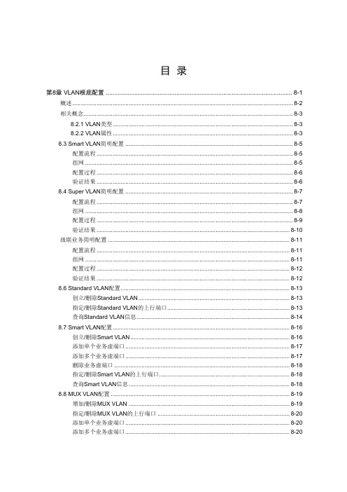
目录第8章 VLAN根底配置 ............................................................................................................... 8-1概述......................................................................................................................................... 8-2相关概念.................................................................................................................................. 8-38.2.1 VLAN类型................................................................................................................ 8-38.2.2 VLAN属性................................................................................................................ 8-38.3 Smart VLAN简明配置 ........................................................................................................ 8-5配置流程.......................................................................................................................... 8-5组网 ................................................................................................................................. 8-5配置过程.......................................................................................................................... 8-6验证结果.......................................................................................................................... 8-68.4 Super VLAN简明配置 ........................................................................................................ 8-7配置流程.......................................................................................................................... 8-7组网 ................................................................................................................................. 8-8配置过程.......................................................................................................................... 8-9验证结果........................................................................................................................ 8-10级联业务简明配置 ................................................................................................................. 8-11配置流程........................................................................................................................ 8-11组网 ............................................................................................................................... 8-11配置过程........................................................................................................................ 8-12验证结果........................................................................................................................ 8-128.6 Standard VLAN配置......................................................................................................... 8-13创立/删除Standard VLAN .............................................................................................. 8-13指定/删除Standard VLAN的上行端口............................................................................ 8-13查询Standard VLAN信息............................................................................................... 8-148.7 Smart VLAN配置.............................................................................................................. 8-16创立/删除Smart VLAN ................................................................................................... 8-16添加单个业务虚端口...................................................................................................... 8-17添加多个业务虚端口...................................................................................................... 8-17删除业务虚端口 ............................................................................................................. 8-18指定/删除Smart VLAN的上行端口................................................................................. 8-18查询Smart VLAN信息.................................................................................................... 8-188.8 MUX VLAN配置 ............................................................................................................... 8-19增加/删除MUX VLAN .................................................................................................... 8-19指定/删除MUX VLAN的上行端口 .................................................................................. 8-20添加单个业务虚端口...................................................................................................... 8-20添加多个业务虚端口...................................................................................................... 8-20删除业务虚端口 ............................................................................................................. 8-21查询MUX VLAN信息 ..................................................................................................... 8-21 8.9 Super VLAN配置.............................................................................................................. 8-22增加/删除Super VLAN ................................................................................................... 8-22添加/删除Sub VLAN ...................................................................................................... 8-22查询Super VLAN信息.................................................................................................... 8-23第8章 VLAN根底配置本章主要介绍以下内容:●概述 8-2●相关概念 8-3●Smart VLAN简明配置 8-5●Super VLAN简明配置 8-7●级联业务简明配置 8-11●Standard VLAN配置 8-13●Smart VLAN配置 8-16●MUX VLAN配置 8-19●Super VLAN配置 8-22说明:●“概述〞介绍了VLAN技术。
德尔格 X-am 5600 使用说明书

使用说明书21)技术手册,传感器技术数据/使用说明书,以及德尔格 X-am5600的电脑软件 CC vision 都包含在 CD 内。
请查阅使用说明书附件中的传感器的技术数据。
为了您的安全请严格遵守使用说明使用本仪器要求完全理解并严格遵守使用说明。
本仪器只能用于说明书中严格规定的用途。
维修保养必须严格遵守本技术手册 1),使用说明,以及德尔格传感器技术数据中所说明的维修保养时间和措施。
仪器只能由经过训练的维修人员进行维修。
配件只能使用技术手册的订货列表中规定的配件。
与电气设备的安全连接使用说明书中未提及的设备需在咨询制造商或专家后与电气设备连接。
在爆炸危险区域的应用根据本国、欧洲或国际防爆规定进行过测试和批准的用于爆炸区域的仪器或配件仅能按照标准中明确规定的条件使用,并应遵守相关的法律规定。
不得对设备或配件进行任何修改。
禁止使用故障或不完整的配件。
在对仪器或配件进行维修时,需始终遵守相应规定。
仪器只能由经过训练的维修人员根据德尔格的维修说明进行维修。
使用说明书中的安全标识使用说明书中使用了一系列可能产生危险的警告标识。
这些警告标识包含一些提醒您可能遇到危险的信号词汇。
这些信号词汇和相应危险如下:设计用途便携式气体检测仪器可用于对工作区域和爆炸性危险区域的环境空气中所含有的几种气体浓度进行连续检测。
根据安装的德尔格传感器不同,仪器可独立检测最多6种气体。
表示如何使用仪器的附加说明。
注意检测和认证见相关的“认证信息”,“标志”。
可以在提供的 CD中找到认证证书。
设计的操作区域及操作条件按区域划分的爆炸性危险区域该仪器设计用于爆炸性危险的区域或矿井,在这些被划分为0区,1区或2区的区域中,可能存在甲烷,操作温度范围为-20°C-+40°C或+50°C。
仪器也用于有IIA,IIB或 IIC类爆炸气体和温度等级为 T3或 T4(取决于应用的电池组和可充电电池)的区域。
如果应用于矿井,仪器只能用于机械碰撞风险较低的区域。
5600控制器使用说明书

安装1、安装的一般要求①、进水压力应在0.2-0.5MPa,当水源压力无法满足要求时,可安装增压水泵提高进水压力。
如果压力过高,应安装减压阀来控制进水压力。
②、进水温度应在5-45℃之间,电源采用交流200V/50Hz。
③、软水器应安装在牢固的平台上,附近有畅通的下水,并留有足够的操作和维修空间。
④、工作环境温度应在5-50℃之间,相对湿度≤95%(5℃时)。
2、控制阀的安装与树脂填装(顶装形式)第一步:首先将下布水器牢固安装在中心管底端,然后插入到树脂罐中央,在中心管上端低于罐口0.5mm处截断并导角,然后用胶带封住中心管口,以防树脂漏入。
第二步:将石英砂沿中心管周围空隙投入树脂罐,并使之在罐底铺平,石英砂高于下布水器上20mm,石英砂应按粒径级别分层铺装,主要起到布水作用(对于直径小于500mm树脂罐一般不装石英砂)。
第三步:将树脂均匀地装入树脂罐中,装至规定的层高后,再向注入10%的食盐溶液,至浸没树脂为止,使树脂充分膨胀。
树脂装填完,应取下中心管的封口胶带,上述操作时应注意使中心管始终保持在树脂罐口的中央位置。
第四步:将上布水器安装到控制阀上,然后将中心管从上布水器内插入到控制阀内,小心地沿顺时针方向转动控制阀,直至旋紧在树脂罐接口上(或用法兰连接固定)。
注意上布水器与控制阀、中心管,下布水器与中心管必须严密,防止树脂跑出。
中心管与控制阀必须严密不漏水,否则会出现窜硬水现象。
3、管道连接要求①、与软水器连接的管道应采用给水塑料管,排水管不得采用软塑料管,防止管道变形,影响排水效果。
②、按照控制阀进出水箭头标记连接进出水管,采用流量型再生控制器,流量计必须安装在出水口。
③、进出水管应装有压力表及手动阀门,同时还应装有旁通阀,在出水管阀前还应安装有取样阀。
进水管阀后一般安装有 Y 型过滤器,防止管道内污物堵塞阀体造成设备无法正常运行。
④、排水管的连接长度不应超过6m,尽量减少弯度,并严禁安装阀门。
27-SmartAX MA5600操作手册 第27章 通用升级流程
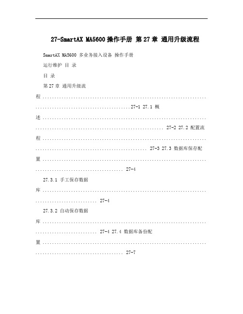
27-SmartAX MA5600操作手册第27章通用升级流程SmartAX MA5600 多业务接入设备操作手册运行维护目录目录第27章通用升级流程 ..................................................................... ........................................27-1 27.1 概述 ..................................................................... ...................................................... 27-2 27.2 配置流程 ..................................................................... ............................................... 27-3 27.3 数据库保存配置 ..................................................................... ..................................... 27-427.3.1 手工保存数据库 ..................................................................... .......................... 27-427.3.2 自动保存数据库 ..................................................................... .......................... 27-4 27.4 数据库备份配置 ..................................................................... ..................................... 27-727.4.1 FTP方式备份 ..................................................................... ............................. 27-727.4.2 TFTP方式备份 ..................................................................... ........................... 27-8 27.5 使用升级工具升级数据 ..................................................................... ........................ 27-10 27.6 加载配套文件 ..................................................................... ...................................... 27-11 27.7 数据库恢复功能配置 ..................................................................... ............................ 27-1227.7.1 复制 ..................................................................... .......................................... 27-1227.7.2 回滚 ..................................................................... .......................................... 27-1227.7.3 擦除 ..................................................................... .......................................... 27-13iSmartAX MA5600 多业务接入设备操作手册运行维护第27章通用升级流程27 本章主要介绍以下内容:, 概述 27-2, 配置流程 27-3, 数据库保存配置 27-4, 数据库备份配置 27-7, 使用升级工具升级数据 27-10, 加载配套文件 27-11, 数据库恢复功能配置 27-12, 说明:, “概述”简单介绍了MA5600升级过程中的步骤,以及数据库保存和备份的区别。
5600全站仪操作手册V3.0

1.配备三种键盘(其他键盘,如:Zeiss 和 GeodatWin 键盘另行介绍):数字键盘(22 键)、字母数字键盘(33 键)和 A/M(只用于瞄准 Aim 和测量 Measure)键盘。两面的键 盘皆为可分离式键盘,可以根据不同测量任务需要配备不同的键盘。键盘上有 RS232 通讯 串口或 PCMCIA 卡槽,用于与计算机通讯或存储数据。
确定好单位以后,可以重新输入仪器工作时的各种参数,ppm Temp 温度 press 气
压 RelHum 相对湿度。完毕自动计算 PPM,还可直接按 F30 修改 PPM,按 ENT 确认。
3、设置时间和日期 MNU,1,4
1) Set time Data=年、月、日
Time=时、分、秒
2) Time System
3
3
§1.2 测量前的设置
将外电池或内电池和主机相连,开机,首先显示电子气泡,进行概略整平,按 ENT 后 初始化补偿器,然后启动 P0 程序,对全站仪作必要的设置,输入当前温度、气压、相对湿 度、棱镜常数和水平度盘定向角,即可完成开机。因为第一次开机时尚无法确定上述各参数 的单位,也可以不用输入数值,待确定单位后重新执行 P0 程序。
12 小时
24 小时
4、选择显示格式 MNU,6,4,
1) Select display
2) Create display
显示格式缺省为 Table 0,用户可另外定义 5 个表(1,2,3,4,5)。
5、小数点后的有效位数:MNU,6,3
输入标识号,Lable=9
SD=3
change to=? 2
2
2
电子手簿,这样几个测量小组可共用一台仪器,只需把测量数据存入各自的键盘。 Trimble5600 系列仪器可同时安装两个键盘,其一为主控制单元(I 面所见),副控制单元(II 面所见),副控制单元的作用主要是方便 II 面操作。I 、II 面的判断依据是:微调螺旋在右 手位置时为 I 面,此时的键盘为主控制单元。
5600中文调试说明书

5600调试说明书1Dial Selection数字面表显示数字面表显示,批处理百分比显示。
2Power Connection供电5600可以接直流或交流24V供电,不要将220V接入设备,会烧坏设备,为了减少电流噪声的影响,电源供电线和数据线要独立走线。
具体连接请按英文说明书第一页第二个图连接3Compatible Sensor Wiring探头的连接我公司的流量探头有两种输出信号:一种为正弦信号(如 515,525,2517等),另一种为方波信号(2000,2507等),探头的连接请按英文说明书第一页第三个图连接。
为了减少电流噪声的影响,电源供电线和数据线要独立走线。
4Batch Contact Wiring 批处理连接(5600与电磁阀的连接)连在背面板上的Batch端,它就相当于一个开关,具体连接请按英文说明书第一页第四个图连接。
5Remote Control Wiring 远程控制开关实现远程控制功能,与背面板的Remote的连接,远程连线最大不要超过30米,具体连接请按英文说明书第二页第一个图连接6End of Batch/Counter Pulse Output Wiring批处理和计数连接实现脉冲计数功能,与背面板的CNT/EOB Output连接,具体连接请按英文说明书第二页第二个图连接。
图A表示计数器的连接;图B表示二个5600的连接(即End of Batch功能)7Option Contact Wiring OptionsOption Contact相当于另一个控制开关,A图表示Two Stage Shutdown (两个阀门比较功能),图在第二页的7AB 图表示无流量告警信号或过流告警信号的接法,图在第二页的7B8Current Output Wiring OptionsA图表示4~20mA的接法,建议还要接一个保险,在第二页的8AB图表示电动阀的接法,在第二页的8B调表步骤:进入菜单:因为要按ENTER键,所以不要在5600的第一个显示项中进入校准菜单,在后面几个显示菜单中再按下面步骤进入Cal和Options菜单STEP 1按住ENTER键:2秒后进入校准程序(CAL),5秒后进入选项程序(OPTIONS) STEP 2密码为 (上上上下),在输入密码后,显示第一个选择项STEP 3用上下键选择菜单STEP 4按右键来选择需要的项目,被修改的项目会闪烁STEP 5对闪烁的项目按上,下键来修改此项目,按右键选择旁边需修改的项目STEP 6按ENTER键储存修改后会自动返回STEP3STEP 7同时按下上下键返回正常状态.一 AUTO CAL的使用使用AUTO CAL时,要确定流出液体的体积(可用灌或桶),由于AUTO CAL 要计算时间,所以泵和AUTO CAL要同时开动或停止,这样计出来的时间会较准,操作过程为在Auto Calibrate <Enter> to Start 菜单下,按下Enter,开始计时,在Auto Calibrate <Enter> to Stop菜单下,按下Enter,停止计时,在Volume 菜单中,输入测量值。
Xam5000and5600多种气体检测仪培训手册视频

Xam5000and5600多种气体检测仪培 训手册视频
密闭空间进入 X-AM 1/2/5000/5600外置泵操作
• 执行测量: - 将德尔格取样管或者德尔格探枪与外置泵进气口 连接 - 执行测量
• 完成操作: - 按下松开键 - LED灯闪烁绿/红灯,短暂发出鸣音 - 外置泵自动关闭
• 再次按“OK ”键 显示故障代码 (参照使用说明书确定故障代码含义.)
• 再按“OK ”键. 可以显示更多故障代码.
• 或者按“+M”键返回测量
Look at video
Xam5000and5600多种气体检测仪培 训手册视频
注意 注意
• 按下“OK ” • 显示注意代码
(参照使用说明书确定故障代码含义.)
• 按下任何键屏幕照明都会打开30秒. • 报警时屏幕照明会自动打开
Look at video
Xam5000and5600多种气体检测仪培 训手册视频
新鲜空气标定菜单
新鲜空气标定
• 此过程为新鲜空气标定,可利用CC Vision软件 或者快捷菜单进行.
• 按下 “+”键三次 • 显示以下图标
• 按下 “OK ”-键并选择新鲜空气标定菜单
Look at video
Xam5000and5600多种气体检测仪培 训手册视频
菜单功能 STEL
• 当STEL分析功能激活后: • 按住“OK”键三秒钟 • 按下 “OK ”键两次 • 屏幕上显示 图标 • 显示STEL 值 • 按下 “OK ”-键或者 “+”键一次 • 仪器返回测量
Look at video
注意!
每次测量前,需要用空气冲洗德尔格取样管活着取样探枪.
5600 系列机械式热探测器安装手册说明书

Before InstallingThis detector must be installed in compliance with the con-trol panel installation manual and meet the requirements of NFPA 72, and/or the local authority having jurisdiction. Read this manual carefully before using the detector. This manual should be left with the owner/user of this equip-ment.General DescriptionThe 5600 series mechanical heat detector is intended for use in property protection applications, or for non-life-safety installations where smoke detection is not practi-cal or appropriate.in lieu of, or in addition to mechanical heat detectors. The 5600 series consists of both single- and dual-circuit heat detectors featuring fixed temperature thermal sensors or combination fixed temperature/rate-of-rise sensors, with temperature ratings of 135ºF (57ºC) or 194ºF (90ºC).Markings on the exterior of the detector indicate the spe-cific activation method and temperature rating. All models are identified as either 135ºF/57ºC or 194ºF/90ºC. Models equipped with combination fixed temperature/rate-of-rise sensors are marked FX/ROR. Fixed temperature only mod-els are marked FX.NOTE: Refer to NFPA72 guidelines for spacing reductions when ceiling heights exceed 10 feet.Non-Resettable Fixed Temperature SensorThe fixed temperature element reacts to heat by respond-ing to a specific temperature setting (135ºF or 194ºF). The detection method is based on the spring action of a metal contact, held to the metal chamber by a fusible alloy. When the temperature reaches the alloy’s melting point, the metal contact will depress the diaphragm, causing the electrical contact to close the circuit. The circular external heat collector is released from the detector to visually indi-cate that the detector has been activated.NOTE: 5600 series Fixed T emperature models (5603, 5604, 5623, and 5624) are non-resettable, and cannot be tested.Self-Restoring Rate-of-Rise (ROR) SensorThe rate-of-rise element responds to a rapid rise of temper-ature, approximately 15ºF (8.3ºC) per minute. As the tem-perature rises, the air within the sealed chamber expands. Should the chamber air expand faster than it can escape through the calibrated vent, the diaphragm is depressed, and the electrical contact closes the circuit.NOTE: Only the ROR element of 5600 series combination fixed temperature/ROR models (5601, 5602, 5621, and 5622) are self-restoring, and may be tested using a hair dryer or heat gun. When testing the ROR element, to pre-vent the activation of the fixed temperature element, the heat source must not exceed the fixed temperature rating of the detector.Mounting BracketAll 5600 series detectors are equipped with a mounting bracket that includes mounting slots to accommodate single-gang, 31⁄2″ octagonal, and 4″ octagonal electrical boxes, as well as 4″ square boxes equipped with a plas-ter ring (Figure 1). The mounting bracket is reversible to accommodate flush-mount and surface–mount installa-tions (Figure 2).INSTALLATION AND MAINTENANCE INSTRUCTIONS3825 Ohio Avenue, St. Charles, Illinois 601741-800-SENSOR2, FAX: 630-377-64955600 SeriesMechanical Heat DetectorSingle Circuit: 5601, 5602, 5603, 5604Dual Circuit: 5621, 5622, 5623, 5624Table 1. 5600 Series Mechanical Heat Detectors Figure 1. Bracket Mounting LocationsA= 31⁄2″ Octagonal boxB= 4″ Octagonal box C= Single gang box and 4″ square with plaster ringD= Directly to Wall/CeilingS T R IP G A U G EBCDDAABCModel No.CircuitTemperatureRatingThermal SensorUL Maximum Spacing(10-foot ceiling)5601Single 135ºF (57ºC)Fixed T emperature/Rate of Rise 50-feet x 50-feet 5602Single 194ºF (90ºC)Fixed T emperature/Rate of Rise 50-feet x 50-feet 5603Single 135ºF (57ºC)Fixed T emperature 25-feet x 25-feet 5604Single 194ºF (90ºC)Fixed T emperature 25-feet x 25-feet 5621Dual 135ºF (57ºC)Fixed T emperature/Rate of Rise 50-feet x 50-feet 5622Dual 194ºF (90ºC)Fixed T emperature/Rate of Rise 50-feet x 50-feet5623Dual 135ºF (57ºC)Fixed T emperature 25-feet x 25-feet 5624Dual194ºF (90ºC)Fixed T emperature25-feet x 25-feetWiring Installation GuidelinesAll wiring must be installed in compliance with the National Electrical Code, applicable state and local codes, and any special requirements of the local Authority Having Jurisdiction. Proper wire gauges should be used. The conductors used to connect heat detectors to the alarm control panel and accessory devices should be color-coded to reduce the likelihood of wiring errors. Improper connec-tions can prevent a system from responding properly in the event of a fire.The non-polarized screw terminals on the back of the detector will accept 14–22 A WG wire. For best system performance, all wiring should be installed in separate grounded conduit; do not mix fire alarm system wiring in the same conduit as any other electrical wiring. T wisted pair may be used to provide additional protection against extraneous electrical interference.Wire connections are made by stripping approximately 1⁄4″ of the insulation from the end of the feed wire, inserting it into the proper base terminal, and tightening the screw to secure the wire in place.InstallationRemove power from the alarm control unit or initiating device circuits before installing detectors.1. Detach the detector from the mounting bracket byrotating the detector 1⁄4 turn counter-clockwise.2. Orient the mounting bracket properly for either aflush- or surface-mount installation (Figure 2).3. Select the pair of mounting holes suitable for the junc- tion box, (figure 1) and secure the bracket to the box.4. Connect the wires to the detector per Figure 3 orFigure 4, as applicable.5. Place the detector onto the mounting bracket by rotat- ing clockwise. The detector will lock into place with a “click”.6. After all detectors have been installed, apply power to the alarm control unit.7. T est each detector as described in Testing.8. Reset all the detectors at the alarm control unit.9. Notify the proper authorities that the system is in oper- ation.Figure 3. Wiring Diagram – Single Circuit ModelsFigure 4. Wiring Diagram – Dual Circuit Models Testing/MaintenanceThe rate-of-rise mechanism may be subject to reduced sen-sitivity over time. Annual testing of the rate-of-rise opera-tion is therefore recommened.Before testing, notify the proper authorities that mainte-nance is being performed and the system will be temporar-ily out of service. Disable the zone or system undergoing maintenance to prevent any unwanted alarms.Only the ROR element of 5600 series combination fixed temperature/ROR models (5601, 5602, 5621, and 5622) are self-restoring, and may be tested using a hair dryer or heat gun.Figure 2. Reversible Mounting BracketEOLControlSurface–mountFlush–mountControlEOLWhen testing the ROR element, to prevent the activation of the fixed temperature element, the heat source must not exceed the fixed temperature rating of the detector.5600 series fixed(5603, 5604, 5623, and 5624) are non-resettable, and cannot be tested.Specifications:Operating Voltage /Contact Ratings 6 – 125 V AC / 3A (Resistive) 6 – 28 VDC / 1A 125 VDC / 0.3A 250 VDC / 0.1A Maximum InstallationT emperature Models 5601, 5603, 5621, and 5623: 100°F (38°C) Models 5602, 5604, 5622, and 5624:150°F (65.6°C)Alarm T emperature Models 5601, 5603, 5621, and 5623: 135°F (57°C) Models 5602, 5604, 5622, and 5624: 194°F (90°C)Rate-of-Rise Threshold 15°F (8.3°C) per minute(models 5601, 5602, 5621, and 5622 only) Operating HumidityRange 5 to 95% RH non-condensing Input T erminals 14 - 22 A WG Back Box Mounting 31⁄2″ octagonal 4″ octagonal Single gang4″ square with a square to round plaster ring Dimensions withmounting bracket Diameter: 4.57 inches (11.6cm) Height: 1.69 inches (4.3cm)Weight 6 oz. (170 grams)Please refer to insert for the Limitations of Fire Alarm SystemsSystem Sensor warrants its enclosed module to be free from defects in materials and workmanship under normal use and service for a period of three years from date of manufacture. System Sensor makes no other express warranty for this module. No agent, representative, dealer, or employee of the Company has the authority to increase or alter the obligations or limitations of this Warranty. The Company’s obli-gation of this Warranty shall be limited to the replacement of any part of the module which is found to be defective in materials or workmanship under normal use and service during the three year period commencing with the date of manufacture. After phoning System Sensor’s toll free number 800-SENSOR2 (736-7672) for a Return Authorization number, send defective units postage prepaid to: System Sensor, Repair Department, RA #__________, 3825 Ohio Avenue, St. Charles, IL 60174.FCC StatementThis device complies with part 15 of the FCC Rules. Operation is subject to the following two conditions: (1) This device may not cause harmful interference, and (2) this device must accept any interference received, including interference that may cause undesired operation.Note: This equipment has been tested and found to comply with the limits for a Class B digital device, pursuant to Part 15 of the FCC Rules. These limits are designed toprovide reasonable protection against harmful interference in a residential installation. This equipment generates, uses and can radiate radio frequency energy and, if not installed and used in accordance with the instructions, may cause harmful interference to radio communications. However, there is no guarantee that interference will not occur in a particular installation. If this equipment does cause harmful interference to radio or television reception, which can be determined by turning the equipment off and on, the user is encouraged to try to correct the interference by one or more of the following measures:– Reorient or relocate the receiving antenna. – Increase the separation between the equipment and receiver. – Connect the equipment into an outlet on a circuit different from that to which the receiver is connected. – Consult the dealer or an experienced radio/TV technician for help.Please include a note describing the malfunction and suspected cause of failure. The Company shall not be obligated to replace units which are found to be defective because of damage, unreasonable use, modifications, or alterations occurring after the date of manufacture. In no case shall the Company be liable for any consequen-tial or incidental damages for breach of this or any other Warranty, expressed or implied whatsoever, even if the loss or damage is caused by the Company’s negli-gence or fault. Some states do not allow the exclusion or limitation of incidental or consequential damages, so the above limitation or exclusion may not apply to you. This Warranty gives you specific legal rights, and you may also have other rights which vary from state to state.Three-Year Limited Warranty。
Xam5600操作使用说明

X-am 5000/5600操作使用一、开机1. 按住 “OK”-键 3 秒钟2. 屏幕倒数 3-2-13. LED 灯闪烁, 声音和振动报警启动自动检测并显示以下内容:A. 已安装软件版本B. 各种报警级别设置C. TWA 和STEL 报警设置D. 下次标定日期二、关机1. 同时按住“+” 和 “OK ” 键超过三秒2. LED 灯闪烁并鸣音3. 仪器关机三、照明显示1. 按下任何键屏幕照明都会打开30秒.2. 报警时屏幕照明会自动打开四、新鲜空气标定XXS 传感器槽 XXS 传感器槽 视觉报警 光报警 催化燃烧传感器分段显示 > 90 db +M – 导航键on – 开机及确认键1. 此过程为新鲜空气标定,可利用CC Vision软件或者快捷菜单进行.2. 按下“+”键三次3. 显示以下图标4. 按下“OK ”-键并选择新鲜空气标定菜单5. 显示真实浓度值6. 按下“OK ”- 键7. 屏幕上显示OK8. 完成新鲜空气标定如果新鲜空气环境下氧气传感器浓度值不为20.9% 或者不稳定, 或者可燃气体或有毒气体传感器不显示“0”,则必须进行新鲜空气标定. 必须在洁净的环境下进行新鲜空气标定.,五、最大值菜单1. 按住“OK”-键3秒钟2. 显示氧气传感器的最大值. 数值从仪器上次重设起开始记录3. 再按“OK”键.4. 屏幕上显示TWA 和STEL 值5. 或者按一下“+”键6. 仪器返回测量模式A.最大值功能显示重设仪器读数后氧气最低浓度值和其它气体最高浓度值。
B.用户可以使用快捷菜单查看最大值也可利用CC vision软件设置最大值数值。
TWA为时间加权平均浓度值,指几乎所有的工人在正常的8小时工作日和40小时工作周内可整日反复地暴露在这样的物质浓度环境下而对健康没有不良的影响.为短时间暴露浓度允许值,指工人在15分钟内可以连续地暴露在这样的环境内而不会遭受;过敏慢性或不可恢复的肌肉损伤足够程度的麻醉而增加以外事故的可能性,不能够自我抢救或者降低工作效率.六、TWA1.当TWA分析功能激活后:2.按住“OK”-键3秒钟3.按下“OK ”-键一次4.屏幕上显示图标5.显示最大工作浓度6.再次按下“OK”-键显示STEL 值.7.或者再按一下“+”键8.仪器返回测量状态七、STEL1.当STEL分析功能激活后2.按住“OK”键三秒钟3.按下“OK ”键两次4.屏幕上显示图标5.显示STEL 值6.按下“OK ”-键或者“+”键一次7.仪器返回测量八、A1 气体浓度报警1.报警级别可以通过CC-Vision软件设置和更改2.单频声音、光和振动报警周期重复出现3.屏幕交替显示“A1” 和气体浓度4.A1报警(除了O2), 可以通过按下“OK ”键确认声音和振动报警.九、A2气体浓度报警1.报警级别可以通过CC-Vision软件设置和更改2.双频声音、光和振动报警周期重复出现3.屏幕交替显示“A1” 和气体浓度4.“A2”或者O2 “A1”声音,光和振动报警都不能被确认(静音)十、STEL 报警1.报警级别可以通过CC-Vision软件设置和更改2.声、光和振动报警周期重复出现,3.屏幕交替显示“A2”和气体浓度4.闪烁图标5.报警无法被确认重设仪器后会取消TWA和STEL值.遵从所述安全操作流程.十一、TWA 报警1.报警级别可以通过CC-Vision软件设置和更改2.声、光和振动报警周期重复出现3.屏幕交替显示“A2”和气体浓度4.闪烁图标5.报警无法被确认重设仪器后会取消TWA和STEL值.遵从所述安全操作流程.十二、A1 低电量报警1.声、光和振动报警周期重复出现2.闪烁图标3.这些报警可以通过选择“OK”静音电池还有不到10分钟操作时间时自动激活此功能请更欢电池或者对仪器进行充电.十三、A2 低电量报警1.声、光和振动报警周期重复出现2.闪烁图标3.仪器倒数10秒后自动关机4.仪器关机5.报警无法确认十四、故障报警1.声、光和振动报警周期重复出现2.屏幕上显示图标3.这些报警可以通过选择“OK”静音,但是屏幕上仍然显示故障图标一旦屏幕上有故障显示需要立即对仪器进行检查。
5600中文说明书(润新)

5600 & 5600型ECONOMINDER®多路阀操作手册本手册包含FLECK5600时间型过滤器(5600FT),软水器(5600ST);流量型软水器(5600SM)的调试操作说明5600产品概述FLECK全自动控制器以闻名于世的FLECK公司软化水技术为基础,它是将软水器的运行及再生的每一个步骤实现全自动控制,并采用时间、流量或感应器等方式来启动再生。
由于FLECK系列全自动软水设备控制系统技术成熟、操作简便、富来控制器采用的工程塑料和无铅黄铜阀体完全符合食品卫生要求,配以聚四氟乙烯(Teflon)涂层,活塞减小了阻力,延长了使用寿命,运行可靠。
FLECK系列全自动软水器可用于家用、工业锅炉、热交换器、宾馆饭店、食品工业、洗衣印染、医疗卫生等行业,该产品具有自动化程度高、交换容量大、结构紧凑、能耗低、省人工、无需日常保养等特点。
系统技术参数进口压力:0.2 Mpa-0.6 Mpa工作温度:2 ℃—50℃进水硬度:符合国家标准出水硬度:≤0.03mmol/L使用电源:220v/50Hz AC布置形式:单罐或双罐串联(二级软化时采用)再生方式:顺流再生操作程序:自动程序控制使用树脂:001×7强酸性阳离子交换树脂我公司将为用户提供完善的技术服务及售后服务。
第1页5600ST安装和启动程序软水器的安装,应根据制造商建议的入水口、出水口和排污口接管,且应符合相关管路规范。
在软水装置接通电源前1.将软水器控制阀手动转至工作位置,打开进出水口,使水流入树脂罐。
直到管路内空气排尽,当水流流出出水口时,关闭进出水口。
注:可手动旋转控制阀前部的旋钮将其拨至不同的再生位置,直到显示软水器处于所需位置。
2.将控制阀手动转至反洗位置,使水经排水口流出3或4分钟。
3.取下控制阀后盖板。
4.确保盐的用量按制造商的建议设置。
如有必要,按设置说明书设置盐的用量。
将控制阀手动转至盐水重注位置,使水填充至空气止回阀顶。
MEA5600系列流量积算仪使用说明书

一、概述MIK2600系列流量积算控制仪采用了表面贴装工艺,全自动贴片机生产,具有很强的抗干扰能力。
本仪表针对现场温度、压力、流量等各种信号进行采集、显示、控制、远传、通讯、打印等处理,构成数字采集系统及控制系统,适用于液体、一般气体、过热蒸汽、饱和蒸汽等的流量积算测量控制。
二、技术规格三、功能可对质量流量自动进行计算和累积可对标准体积流量自动进行计算和累积可同时显示瞬时流量测量值及流量累积值(累积值单位可任意设定)可切换显示瞬时流量测量值、时间、本次累积值、整十一位流量总累积值、流量(差压、频率)输入值、压力补偿输入值、温度补偿输入值可设定流量小信号切除功能(瞬时流量值小于设定值时显示为0)可设定流量定量控制功能可自动进行温度、压力补偿可编程选择以下几种传感器形式:1、ΔP 输入为差压式流量传感器2、ΔP 、T 输入为差压式流量传感器和温度传感器3、ΔP 、P 、T 输入为差压式流量传感器、压力传感器和温度传感器4、f 输入为频率式流量传感器5、f 、T 输入为频率式流量传感器和温度传感器6、f 、P 输入为频率式流量传感器、压力传感器7、f 、P 、T 输入为频率式流量传感器、压力传感器和温度传感器8、G 输入为流量传感器(线性流量信号)9、G 、T 输入流量传感器和温度传感器10、G 、P 输入为流量传感器和压力传感器11、G、T 、P 输入为流量传感器、温度传感器和压力传感器具有三种补偿功能温度自动补偿压力自动补偿温度和压力自动补偿显示功能可显示通道的瞬时流量测量值、本次累积值、累积值、差压测量值、压力补偿测量值、温度补偿测量值及频率测量值等PV+SV显示累积流量值为整十一位(0~99999999999字)当前日期、当前时间显示流量总累积值断电保持,累积总量满量程(99999999999字)时自动清零,本次累积值断电不保持。
四、仪表的面板及显示功能1)仪表外形尺寸及开孔尺寸外形尺寸开孔尺寸160*80mm(横式)152*76mm80*160mm(竖式)76*152mm96*96mm(方式)92*92mm2)显示窗PV显示窗(整五位显示):显示瞬时流量值;在参数设定状态下,显示参数符号;可设定为显示流量、压力补偿、温度补偿输入值SV显示窗(整八位显示):显示累积流量值;在参数设定状态下,显示设定参数值PV+SV显示窗(整十一位显示):可设定仪表内部参数,使仪表显示整十一位累积值(累积的百万位显示在PV显示器后三位)3)面板指示灯AL1:第一报警指示灯AL2:第二报警指示灯时间:当前时间显示指示灯瞬时:瞬时流量显示指示灯温度:温度补偿显示指示灯压力:压力补偿显示指示灯流量:差压、流量显示指示灯本累:本次累积显示指示灯4) 操作按键确认键:数字和参数修改后的确认.翻页键:参数设置下翻键配合键可实现累积流量值清零功能,配合键可实现设定小数点循环左移功能位移键:按一次数据向左移动一位反回键:长按2秒可返回上一级参数减少键:用于减少数值增加键:用于增加数值5)仪表配线仪表在现场布线注意事项:PV 输入(过程输入)1. 减小电气干扰,低压直流信号和传感器输入的连线应远离强电走线。
5600_5600SE_中文操作手册
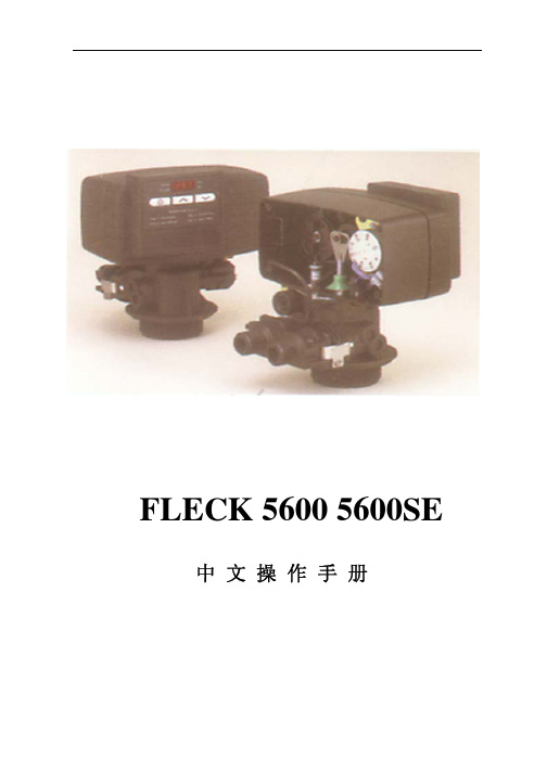
b、 产水量设定 按动 Up 或 Down 键可以设定软水器再生前的产水量; c、 再生时间设定 按动 Extra Cycle 键,程序进入再生时间设定,通过按动 Up 或 Down
RINSE)、盐箱注水(BRINE REFILL)。
调试工作
1、 调整控制器到工作位置,让水流进树脂罐,当水流停止时,打开阀门以放尽罐中空气, 然后关闭;
2、 插上电源,观察是否工作; 3、 控制器时间设定 按动 Up 或 Down 键可调整时间,连续按住可连续调整; 4、 控制器简单编程(控制器时间非 12:01PM)
8、盐箱充水
硬水经控制器进水口,向下通过树脂 层,然后向下流过下布水器、中心管, 最后通过排水口流出。
硬水经控制器进水口,经过射流器、盐阀、 流量控制板给盐箱充水,同时硬水流过阀 体凹槽向下经过树脂层,被软化后进入布 水器、中心管,最后通过出水口流出。
5
5600 5600SE 中文操作手册
设备的安装和运行
(PRELIMINARY RINSE)、反洗(BACKWASH)、吸盐与慢洗(BRINE & SLOW RINSE)、快洗 (RAPID RINSE)、稳层清洗(SETTLING RINSE)、盐箱注水(BRINE TANK FILL)。
时间型
流量延时再生型
8
5600 5600SE 中文操作手册
调试工作
7
5600 5600SE 中文操作手册
FLECK5600 控制器(流量型/时间型) 调试步骤
准备工作和注意事项
a、 设备在调试及运行前应按厂家要求安装完毕进、出水、排污管道和阀门; b、 自来水、电源及排水沟准备就绪; c、 打开旁通阀,让自来水冲洗管道至出水变清,然后关闭阀门; d、 控制器手动再生旋钮只可顺时针旋转,相应位置分别为:工作(SERVICE)、预清洗
气体检测仪-X-am 5600多合一气体检测仪说明书
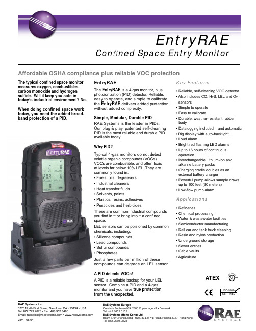
Key Features• Reliable, self-cleaning VOC detector • Also includes CO, H 2S, LEL and O 2 sensors• Simple to operate • Easy to calibrate• Durable, weather-resistant rubber body• Datalogging included _and automatic • Big display with auto-backlight • Loud alarm • Bright red fl ashing LED alarms • Up to 16 hours of continuous operation• Interchangeable Lithium-ion and alkaline battery packs• Charging cradle doubles as an external battery charger• Powerful pump allows sample draws up to 100 feet (30 meters)• Low-fl ow pump alarmApplications• Re fi neries• Chemical processing• Water & wastewater facilities • Semiconductor manufacturing • Rail car and tank truck cleaning • Resin and nylon production • Underground storage • Sewer entries • Cable vaults • AgricultureThe typical con fi ned space monitormeasures oxygen, combustibles,carbon monoxide and hydrogen sul fi de. Will it keep you safe intoday ,s industrial environment? No.When doing confined space work today, you need the added broad-band protection of a PID.EntryRAEThe EntryRAE is a 4-gas monitor, plusphotoionization (PID) detector. Reliable, easy to operate, and simple to calibrate, the EntryRAE delivers added protection without added complexity.Simple, Modular, Durable PID RAE Systems is the leader in PIDs.Our plug & play, patented self-cleaning PID is the most reliable and durable PID available today.Why PID?Typical 4-gas monitors do not detect volatile organic compounds (VOCs). VOCs are combustible, and often toxic at levels far below 10% LEL. They are commonly found in:• Fuels, oils, degreasers • Industrial cleaners • Heat transfer fl uids • Solvents, paints• Plastics, resins, adhesives • Pesticides and herbicidesThese are common industrial compoundsyou fi nd in _ or bring into _a con fi ned space.LEL sensors can be poisioned by common chemicals, including:• Silicone compounds • Lead compounds • Sulfur compounds • PhosphatesJust a few parts per million of thesecompounds can degrade an LEL sensor. A PID detects VOCs!A PID is a reliable backup for your LEL sensor. Combine a PID and a 4-gas monitor and you have true protection from the unexpected.Affordable OSHA compliance plus reliable VOC protectionEntryRAECon fi ned Space Entry MonitorRAE Systems Inc.RAE Systems EuropeATEXMonitor only includes:• Monitor as speci fi ed • VOC sensor (PID)• CO, H 2S, LEL and O 2 sensors• Lithium-ion rechargeable calibration adapter battery • Alkaline battery adapter • 5 external fi lters • Charging cradle- 120 V wall charger, US plug, or 230 V wall charger, Euro plug • ProRAE Studio software package • Computer interface cable- RS232 to RS232 with USB adapter • Calibration adapter • User manual • Shipping caseOptional CSK II Calibration Kit• Hard transport case with pre-cut foam • Sampling wand with 15 feet (3 meters) of self-coiling Te fl on ® tubing • Tool kit• Four-gas mix – 34L (50% LEL, 20.9% O 2, 10 ppm, H 2S, 50 ppm CO)• Isobutylene – 34L (100 ppm, balance air)• Regulators and tubingTruck Mount (Accessory)• Cradle attachment for mounting on a wall • 12 V adapterAutoRAE Docking Station (Accessory)• Automated bump test and calibration system• Drop-in, pushbutton operationRAE Systems Inc.RAE Systems EuropeEntryRAESpeci fi cations *Sensor Speci fi cationsOngoing projects to enhance our products mean that these speci fi cationsare subject to change.D I S T R I B U TE D B Y :AutoRAE Docking StationTruck Mount。
共立5600中文使用说明书

MODEL5600/5601 使用说明书1. 产品种类品名 型号内容MODEL 5600MODEL 5600本体 单4电池4节, 反射胶带10个 手携式转速计MODEL 5601(8点存储,显示单位切换)MODEL 5600本体 单4电池4节, 反射胶带10个接触测定用适配器MODEL 8089(5600和5601均可使用)适配器本体橡胶接触头3个 周速轮(外周1/10m )延长光电探棒MODEL 8090(5600和5601均可使用)延长光电探棒 (φ21 导线最长1m )2. 各部件名称橡胶接触头 延长光电探棒单位显示 反射光检测显示延长光电探棒用接口内部电池盒的滑动开关切换后可使用延长探棒测试线3. 使用前准备3.1 电池安装1.用手指按住转速计背面电池盖的部分向下移动,打开电池盖。
2.仪器电池盒内部的滑动开关可设置ON(仅仪器本体、本体+适配器使用时)或OFF(延长光电探棒使用时)。
3.将电池(单4)4节按正确位置放入。
4.将电池盖盖上并安装。
3.2 反射胶带的安装——使用非接触式时将标配的反射胶带剪下1~3米长度,撕下胶带背面的牛皮纸,将其贴在被测旋转体上。
z请先擦拭贴胶带处的油污和脏物。
z请尽量将胶带贴在最靠近旋转体外周的地方。
3.3 接触式适配器的安装——使用接触式时将转速计背面的锁定螺丝拧松,接触测定用适配器从仪器上方插入后使用螺丝刀将螺丝固定。
没有螺丝刀时可借助硬币拧紧。
请确保适配器在使用中不会松动。
3.4 延长光电探棒的安装仪器电池盒中的滑动开关设置为OFF后将延长光电探棒的接头插入仪器左侧的标准接口。
4.测量4.1 使用非接触式测量时(1.)使仪器本体或延长光电探棒与所贴胶带保持5~30cm的距离,光的投射角度设定在±30°以内。
(2.)按测试开关,确认显示屏出现“”标志后读取测试值。
(3.)松开测试开关后,测试值将保留3分钟,然后切断电源。
* MODEL 5601在按键操作完成后3分钟自动切断电源。
- 1、下载文档前请自行甄别文档内容的完整性,平台不提供额外的编辑、内容补充、找答案等附加服务。
- 2、"仅部分预览"的文档,不可在线预览部分如存在完整性等问题,可反馈申请退款(可完整预览的文档不适用该条件!)。
- 3、如文档侵犯您的权益,请联系客服反馈,我们会尽快为您处理(人工客服工作时间:9:00-18:30)。
X-am 5000/5600操作使用 1
2
3
4
5
6
7
8
9
10
11
12
13
14
15
16
17
18
19 一、开机 20 XXS 传感器槽 XXS 传感器槽 视觉报警 光报警 催化燃烧传感器 分段显示 报警声音 > 90 db +M – 导航键 OK on – 开机及确认键
21
1.按住“OK”-键 3 秒钟
22
2.屏幕倒数 3-2-1
23
3.LED灯闪烁, 声音和振动报警启动
24
自动检测并显示以下内容:
25
A.已安装软件版本
26
B.各种报警级别设置
27
C.TWA 和STEL报警设置
28
D.下次标定日期
29
二、关机
30
1.同时按住“+” 和“OK” 键超过三秒
31
2.LED灯闪烁并鸣音
32
3.仪器关机
33
三、照明显示
34
1.按下任何键屏幕照明都会打开30秒.
35
2.报警时屏幕照明会自动打开
36
四、新鲜空气标定
37
1.此过程为新鲜空气标定,可利用CC Vision软件或者快捷菜单进行.
38
2.按下“+”键三次
39
3.显示以下图标
40
4.按下“OK ”-键并选择新鲜空气标定菜单
41
5.显示真实浓度值
42
6.按下“OK ”- 键
43
7.屏幕上显示OK
44
8.完成新鲜空气标定
45
如果新鲜空气环境下氧气传感器浓度值不为20.9% 或者不稳定, 或者可燃气体46
或有毒气体传感器不显示“0”,则必须进行新鲜空气标定. 必须在洁净的环境下47
进行新鲜空气标定.,
48
五、最大值菜单
49
1.按住“OK”-键3秒钟
50
2.显示氧气传感器的最大值. 数值从仪器上次重设起开始记录
51
3.再按“OK”键.
52
4.屏幕上显示TWA 和STEL 值
53
5.或者按一下“+”键
54
6.仪器返回测量模式
55
A.最大值功能显示重设仪器读数后氧气最低浓度值和其它气体最高浓度
56
值。
57
B.用户可以使用快捷菜单查看最大值也可利用CC vision软件设置最大值
58
数值。
59
60
TWA为时间加权平均浓度值,指几乎所有的工人在正常的8小时工作日和40小时61
工作周内可整日反复地暴露在这样的物质浓度环境下而对健康没有不良的影响. 62
为短时间暴露浓度允许值,指工人在15分钟内可以连续地暴露在这样的环境内而63
不会遭受;
64
过敏
65
慢性或不可恢复的肌肉损伤
66
足够程度的麻醉而增加以外事故的可能性,不能够自我抢救或者降低工67
作效率.
68
六、TWA
69
1.当 TWA分析功能激活后:
70
2.按住“OK”-键3秒钟
71
3.按下“OK ”-键一次
72
4.屏幕上显示图标
73
5.显示最大工作浓度
74
6.再次按下“OK”-键显示STEL 值.
75
7.或者再按一下“+”键
76
8.仪器返回测量状态
77
七、 STEL
78
1.当STEL分析功能激活后
79
2.按住“OK”键三秒钟
80
3.按下“OK ”键两次
81
4.屏幕上显示图标
82
5.显示STEL 值
83
6.按下“OK ”-键或者“+”键一次
84
7.仪器返回测量
85
八、A1 气体浓度报警
86
1.报警级别可以通过CC-Vision软件设置和更改
87
2.单频声音、光和振动报警周期重复出现
88
3.屏幕交替显示“A1” 和气体浓度
89
4.A1报警(除了O2), 可以通过按下“OK ”键确认声音和振动报警.
90
九、A2气体浓度报警
91
1.报警级别可以通过CC-Vision软件设置和更改
92
2.双频声音、光和振动报警周期重复出现
93
3.屏幕交替显示“A1” 和气体浓度
94
4.“A2”或者O2 “A1”声音,光和振动报警都不能被确认(静音)
95
十、 STEL 报警
96
1.报警级别可以通过CC-Vision软件设置和更改
97
2.声、光和振动报警周期重复出现,
98
3.屏幕交替显示“A2”和气体浓度
99
4.闪烁图标
100
5.报警无法被确认
101
重设仪器后会取消TWA和STEL值.遵从所述安全操作流程.
102
103 报警
十一、TWA
104
1.报警级别可以通过CC-Vision软件设置和更改
105
2.声、光和振动报警周期重复出现
106
3.屏幕交替显示“A2”和气体浓度
107
4.闪烁图标
108
5.报警无法被确认
109
重设仪器后会取消TWA和STEL值.遵从所述安全操作流程.
110
十二、 A1 低电量报警
111
1.声、光和振动报警周期重复出现
112
2.闪烁图标
113
3.这些报警可以通过选择“OK”静音
114
电池还有不到10分钟操作时间时自动激活此功能
115
请更欢电池或者对仪器进行充电.
116 量报警
十三、A2 低电
117
1.声、光和振动报警周期重复出现
118
2.闪烁图标
119
3.仪器倒数10秒后自动关机
120
4.仪器关机
121
5.报警无法确认
122
十四、故障报警
123
1.声、光和振动报警周期重复出现
124
2.屏幕上显示图标
125
3.这些报警可以通过选择“OK”静音,但是屏幕上仍然显示故障图标126
一旦屏幕上有故障显示需要立即对仪器进行检查。
仪器应进行专业维护排除故障
127
后方能正常使用。
128
十五、超量程
129
1.声、光和振动报警周期重复出现
130
2.屏幕上交替显示和A1
131
3.此报警无法被确认
132
如果超出测量范围,屏幕上会有如下显示。
133
请遵照安全操作流程.
134
135
十六、低于量程
136
1.声、光和振动报警周期重复出现
137
2.屏幕上显示
138
3.此报警无法被确认
139
测量浓度趋于负量程。
如果存在一定浓度气体时进行了新鲜空气标定,有可能存140
在这种情况。
请在洁净环境下对仪器进行新鲜空气标定。
141 显示
十七、故障
142
1.按“OK ”键进行确认
143
2.再次按“OK ”键显示故障代码 (参照使用说明书确定故障代码含义.) 144
3.再按“OK ”键. 可以显示更多故障代码.
145
4.或者按“+M”键返回测量
146 意
十八、注
147
1.按下“OK ”
148
2.显示注意代码 (参照使用说明书确定故障代码含义.) 149
3.再按“OK ”键.显示更多注意代码
150
4.或者按下“+M”键返回测量状态
151
152。
