dw5600e说明书
戴尔在线机架式UPS 5600W 用户指南说明书
Dell t在线机架式UPS5600W用户指南Dell5600R OL HV-US,Dell5600R OL HVK812N w w w.d e l l.c o m|s u p p o r t.d e l l.c o m注意和警告注意:“注意”表示可帮助您更好使用本产品的重要信息。
小心:“小心”表示潜在危险情况,如果不加以避免,可能导致轻度或中度伤害,或财产损失事故。
警告:“警告”表示潜在危险情况,如果不加以避免,可能会导致死亡或伤害。
危险:“危险”表示紧急危险情况,如果不加以避免,将导致死亡或严重的伤害。
危险:遵守下列须知有助于防止紧急危险情况,其若不加以避免,将导致死亡或严重的伤害:S本UPS包含危险致命的电压。
所有维修和服务都只能由经过授权的维修人员进行。
UPS中没有用户可自行维修的部件。
小心:此为A级产品,在生活环境中,该产品可能会造成无线电干扰。
在这种情况下,可能需要用户对干扰采取切实可行的措施。
本文档所含信息如有更改,恕不另行通知。
©2009–2013Dell Inc.保留所有权利。
未经Dell Inc.书面允许,严禁以任何形式进行复制。
本文中使用的商标:Dell和DELL徽标是Dell Inc.的商标;Greenlee是Greenlee Textron的注册商标;National Electrical Code及NEC是National Fire Protection Association,Inc.的注册商标;Phillips是Phillips Screw Company的注册商标。
本文件中可能会使用其它商标或商业名称来指称拥有该商标或名称权利的实体或其产品。
Dell Inc.对不属于自己的商标和商品名称,不拥有任何权利。
2013年7月•1642018983目录1简介......................................................查找信息8 2安全警告3安装检查设备11............................................................................................................机箱拆包12....................................................UPS后面板14UPS前面板15..........................................................................................................机架安装16......................................................安装EBM23安装UPS23................................................................................................安装远程应急电源关闭24UPS输入硬连线26..................................................................................................UPS初始启动30 4操作UPS启动和关机31..................................................................................................启动UPS31...........................................通过电池启动UPS32..................................................UPS关机32..................................................控制面板功能33......................................................变更语言343目录|显示功能34........................................................................................................开机屏幕34..................................................屏幕锁定35..................................................UPS状态35..................................................事件日志38......................................................测量39..................................................控制屏幕40......................................................标识41......................................................设置41......................................UPS在各种模式之间的转换46.................................从“正常”转为“旁路”模式46.................................从“旁路”转为“正常”模式46撷取事件日志46................................................................................................过载情况下的表现47..............................................配置输出开关控制48.................................通过显示屏控制输出开关控制48...........................................配置自动输出延迟49.................................配置电池模式后自动关闭延迟50配置电池设置51.............................................................................................为配置UPS EBM51...........................................运行自动电池自检52配置自动电池自检52.............................................................................................配置自动重启52 5其它UPS特性........................................RS-232和USB通讯端口53Dell网络管理卡(可选)55...................................................................................Dell UPS管理软件564|目录6UPS维护................................................UPS和电池保养57......................................................运输UPS57...............................................存放UPS和电池59..................................................何时更换电池59..................................................进行电池自检60.................................................更新UPS固件607规格8故障排除................................................获取警报和情况65..............................................UPS状态菜单65...............................................事件日志菜单66................................................典型警报与状况66....................................................使警报消声715目录|1简介Dell t在线机架式不间断电源(UPS)可保护您敏感的电子设备免受基本电力问题的损害,如停电、电压突降、电压浪涌、电压不足和传输线干扰。
5600(V5.0)高精密数字温度计使用说明书

3
3. 输入接线及注意事项
Thermocouple PT D or Resistor mV or mA Thermocouple wire Constant temperature bath Copper lugs Copper wire Copper wire × 4 Thermocouple wire Copper wire Copper wire Thermocouple Pt100
]=1、热电偶采用 _ ]值、FILt [ ]值有关。 _ ]=1、FILt[
2) 测量条件:仪表在稳定的温湿度环境下放置 1h、开机时间 5min 后,S_rAtE[ MAN 补偿方式,输入 80%FS 稳定的信号。
_ ]设置。 _
(4) 采样速率:采样速率由菜单参数 S_rAtE[
输入信号 热电偶 (INT/EXT 补偿) 其他输入信号
4. 显示屏
1.数学功能 5.保持 2.低电压
4.整体修正或 传感器修正
3.自动关机 6.单位
7.主显示
8.热电阻热 电偶分度号
9.热电偶参 考端温度补 偿方式
10.下限上 限报警
(1) REL/MAX/MIN/AVG/P-P/SN:数学功能,分别代表:相对值、最大值、最小值、平均 值、峰-峰值、标准差和采样数。其中标准差和采样数都用“SN”作为标识; (2) LOWBAT:当电池电压低时显示此标识; (3) AUTOOFF:当设置自动关机时显示此标识; (4) –T2/OFFSET:带有整体修正时的示值用“-T2”标识,而当菜单中传感器平移修正值 OFFSEt≠0 时,显示 “OFFSET” 标识; (5) HOLD:显示保持; (6) mVAΩ℃℉K:测量单位; (7) 6 位 LCD 显示:测量值或提示信息; (8) Pt100/Pt1000/Cu50/Cu100/K/J/T/S/R/E/N/B:热电阻和热电偶分度号。而Ω档、mV 档、mA 档没有“分度号” ,仅以其显示单位Ω、mV、mA 进行标识; (9) INT/EXT/MAN:热电偶参考端的补偿方式; (10) LOAL/HIAL:分别表示下限报警、上限报警。
【首晒】经典最弥久:CASIO 卡西欧 G-SHOCK DW5600E-1V 男款经典腕表
DW5600是卡西欧(CASIO)第一块真正意义上的G-SHOCK,虽然不是第一块命名为G-SHOCK的表,但G-SHOCK 的成名由此而来,连第一块BABY-G也是由它的衍生型-DW500而来。
作为历史上销量最好的G-SHOCK款色,它以最初型号的款色从来未被从G-SHOCK的名单上剔除过。
小学的时候正是电子表流行的年代,从路边的小卖部到商场的柜台都能见到各种新奇样式的电子表,当时新鲜的功能无非是背光,秒表,倒计时,还有带计算机功能的,升初中的时候我终于有了第一块表5600,当时对于这块表背后的文化啊什么的一概不知道,就知道这只表有背光,爸妈给我买这块表的原因很简单--放学后别贪玩按时回家。
就这样5600从初中一直陪伴我到大学,念大学的时候有了第一块手机,手机有时间显示,看时间设定闹铃又方便,渐渐地5600就进入了“箱底”。
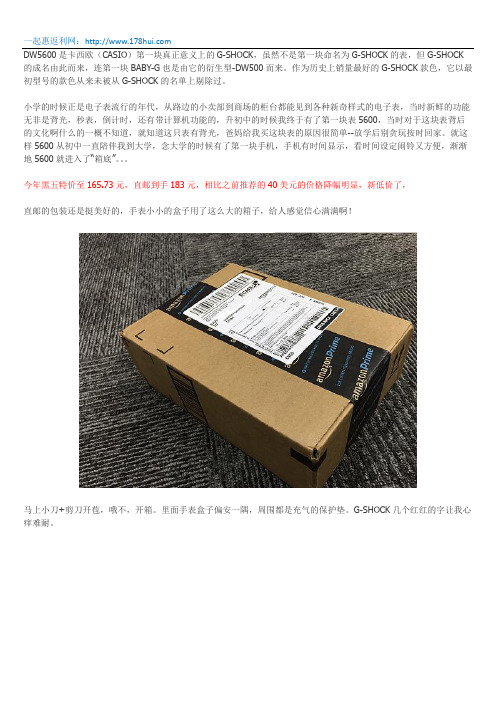
今年黑五特价至165.73元,直邮到手183元,相比之前推荐的40美元的价格降幅明显,新低价了,直邮的包装还是挺美好的,手表小小的盒子用了这么大的箱子,给人感觉信心满满啊!马上小刀+剪刀开苞,哦不,开箱。
里面手表盒子偏安一隅,周围都是充气的保护垫。
G-SHOCK几个红红的字让我心痒难耐。
取出小盒子,尼玛说好的小铁盒呢?怎么尼玛就是一破纸盒子啊~~~~马上上网搜索晒物,原来这个价位就只是这么一个纸盒子。
好吧,继续开苞,哦不,开箱~打开盒子,就是这么一个小支架映入眼帘:隐约中还有膜~~犹抱琵琶半遮面,朦(chu)胧(nv)美(mo),我喜欢掀起了你的盖头来,让我来看看你的脸~~呆萌小方脸跃然而出~~从这里可以看出,做为一款入门级的G-shock ,没有电没有波,但是整体做工还是可以的,对于我这么个大大咧咧的人来说,这个质感已经让我很满足了。
这里面就是所有的东西了,底座,说明书,手表和国际联保卡,里面有广州,北京,上海三家联保单位哦~按理说应该也能享受国际联保一年~说明书非常薄,我也懒得看,有需要说明书的,大家可以上casio 的中国官网下载,按机芯型号搜索,机芯型号就是3229~非常简单,但是就是纯朴,耐用~~你看那200m 防水~左上角的A 键跟其他3个略微不同,是有一点凹陷的,必须用指甲戳才能有反应,这正是设计的细节,因为A 键就是用来调时间的,做的下陷一点,不容易误操作。
5600SE下风过滤器系统操作指南说明书

Master Programming Mode Flow Chart for Single Backwash ValvesWith Time of Day display set to 12:01 P.M., push and hold both the Set Up and Set Down buttons for 5 /Metric Display FormatExample: US display Format [U--1]Regeneration TypeExample: Meter Delayed Regeneration [7--3]Treated Water CapacityExample: 1,000 gallons/liters/cubic meters [1000]Regeneration TimeExample: Regenerate as needed at 2:00 A.M. [2:00]Regeneration Day OverrideExample: Regenerate at a minimum frequency of 3 days [A--3]Regeneration Cycle Step #1Example: 10 minute step time [1-10]Regeneration Cycle Step #2Example: 60 minute step time [2-60]Regeneration Cycle Step #3Example: 10 minute step time [3-10]Regeneration Cycle Step #4Example: 12 minute step time [4-12]Regeneration Cycle Step #5Example: Step 5 Cancelled [5OFF]Flow Meter SizeExample: 5600SE 3/4" Turbine Flow Meter [F133]Valve TypeExample: 5600SE Valve [o--1]Line FrequencyExample: 60 Hz Line Frequency [LF60]Master Programming Mode is exited,Normal Operation is resumedNOTE:1.Set Time of Day display to 12:01 P.M.2.Push and hold both the Set Up and Set Down buttons for 5 seconds.3.Push Extra Cycle button once per display until all displays are viewed and Normal Operation is resumed.4.Option setting displays may be changed as required by pushing either the Set Up or Set Down button.5.Depending on current valve programming certain displays will not be able to be viewed or set.6.Reference programming instructions for complete list of available settings.Page 1Master Programming Mode Flow Chart for Double Backwash ValvesWith Time of Day display set to 12:01 P.M., push and hold both the Set Up and Set Down buttons for 5 /Metric Display FormatExample: US display Format [U--1]Regeneration TypeExample: Meter Delayed Regeneration [7--3]Treated Water CapacityExample: 1,000 gallons/liters/cubic meters [1000]Regeneration TimeExample: Regenerate as needed at 2:00 A.M. [2:00]Regeneration Day OverrideExample: Regenerate at a minimum frequency of 3 days [A--3]Regeneration Cycle Step #1Example: 10 minute step time [1-10]Regeneration Cycle Step #2Example: 60 minute step time [2-60]Regeneration Cycle Step #3Example: 10 minute step time [3-10]Regeneration Cycle Step #4Example: 10 minute step time [4-10]Regeneration Cycle Step #5Example: 12 minute step time [5-12]Regeneration Cycle Step #6Example: Step 6 Cancelled [6OFF]Flow Meter SizeExample: 5600SE 3/4" Turbine Flow Meter [F133]Valve TypeExample: 5600SE Valve [o--1]Line FrequencyExample: 60 Hz Line Frequency [LF60]Master Programming Mode is exited,Normal Operation is resumedNOTE:1.Set Time of Day display to 12:01 P.M.2.Push and hold both the Set Up and Set Down buttons for 5 seconds.3.Push Extra Cycle button once per display until all displays are viewed and Normal Operation is resumed.4.Option setting displays may be changed as required by pushing either the Set Up or Set Down button.5.Depending on current valve programming certain displays will not be able to be viewed or set.6.Reference programming instructions for complete list of available settings.Page 2Master Programming ModeSet Up buttonExtra Cycle button Set Down buttonWhen the Master Programming Mode is entered, all available option setting displays may be viewed and set as needed. Depending on current option settings, some displays cannot be viewed or set.Entering Master Programming ModeSet the Time Of Day display to 12:01 P.M. Push and hold the Set Up and Set Down buttons together until the Program Dot turns on (about 5 seconds). Depending on current option settings, some displays cannot be viewed or set.Exiting Master Programming ModePush the Extra Cycle button once per display until all are viewed. The Program Mode is exited and normal operation resumes. Resetting Permanent Programming MemoryPush and hold the Set Up and Set Down buttons for 25 seconds or until the Time Of Day display resets to 12:00 P.M. All option settings reset to default values. Control programming must be reset as necessary./Metric Display Format (U)Push the Extra Cycle button. This display is used to set the desired display format. This option setting is identified by the "U"in the first digit. The possible settings are:US Format uses gallons for volume with a 12-hour timekeeping format. Regeneration timing in minutes.Example:[U - - I]Metric Format uses liters for volume and a 24-hour timekeeping format. Regeneration timing in tenths of minutes. Use the Set Up and Set Down buttons to adjust this value.Example:[U - - 2]Cubic Meter Format uses cubic meters for volume and a 24-hour timekeeping format. Regeneration timing in tenths of minutes. Use the Set Up and Set Down buttons to adjust this value.Example:[U - - 4]Page 3Master Programming Mode (Cont’d.)2.Regeneration Type (7)Push the Extra Cycle button. Use this display to set the Regeneration Type. This option setting is identified by the number "7"in the first digit. There are three possible settings:Timeclock DelayedThe control determines the day that a regeneration is required by the Regeneration Day Override setting (A). Once this day is reached, a regeneration cycle starts at the set Regeneration Time.Example:[7 - - I]Meter ImmediateThe control determines that regeneration is required when the available volume of treated water drops to zero. Regeneration begins immediately.Example:[7 - - 2] (This setting is typically used by the 9000SE)Meter DelayedThe control determines that a regeneration is required when the available volume of treated water drops to zero. Regeneration begins immediately at the set Regeneration Time. Use the Set Up and Set Down buttons to adjust this value.Example:[7 - - 3]3.Treated Water Capacity (No Display Code)Push the Extra Cycle button. Use this display to set the amount of water (gallons/liters/cubic meters) that can be treated by the unit before a regeneration cycle is required. With Meter Delayed Regeneration Type set, it is necessary for the programmer to determine a reserve capacity and subtract that value from the calculated full capacity of the unit. This display cannot be viewed with Timeclock Regeneration Type set. Use the Set Up and Set Down buttons to adjust this value.Example:Regenerate every 700 gallons/liters/cubic meters —[7 0 0]4.Regeneration Time (Clock Display Without a Flashing Colon)Push the Extra Cycle button. The next display that appears is the option setting for Regeneration Time. It is identified by a clock display without a flashing colon. Set the desired time of day that a regeneration may occur. This display cannot be viewed with Meter Immediate Regeneration Type set. Use the Set Up and Set Down buttons to adjust this value.Example: 2 o'clock A.M. Regeneration Time —[2: 0 0] (A.M. Indicator Dot On)5.Regeneration Day Override (A)Push the Extra Cycle button. Use this display to set the maximum amount of time (in days) the unit can be in service withouta regeneration. This option setting is identified by the letter "A" in the first digit.–With Timeclock or Meter Delayed Regeneration Types selected, regeneration begins at the set Regeneration Time.–With Meter Immediate Regeneration Type selected, regeneration begins at the same time of day that the last regeneration cycle was initiated. An OFF setting cancels this feature with all regeneration types except Timeclock Regeneration were it must be used. Use the Set Up and Set Down buttons to adjust this value.Example:Override every 7 days — [A - - 7]Cancel setting — [A O F F] (Meter Immediate or Delayed Regeneration Types Only)Page 4Master Programming Mode (Cont’d.)6.Regeneration Cycle Step Programming (1) (2) (3) (4) (5) (6)Push the Extra Cycle button. The next 2–6 displays that appear are part of a series of option settings used to program the Regeneration Cycle. Each display is used to set in minutes (or tenths of minutes - Metric). A step # turns on for theregeneration cycle step being programmed.–Skip regeneration steps by setting the display to 0–End a regeneration cycle by setting the step # after the last active step to OFF, as shown below:Example:Regeneration Cycle Step #1, 8 minutes —[I - - 8](US Format)Regeneration Cycle Step #3, skipped — [3 - - 0] (US Format)Regeneration Cycle Step #4, 8.5 minutes —[4 - 8.5] (Both Metric Formats)Regeneration Cycle Step #4, cancelled —[4 O F F] (All Formats)Push the Extra Cycle button once per display to advance through Regeneration Cycle Step Programming.Proper softener operation requires the calculation of a brine tank refill time:(Pounds of Salt Used per Regeneration Cycle ÷ 3) ÷ BLFC Size = Refill Time in MinutesExample:(10 lbs salt ÷ 3) ÷ 0.25 gpm = 13.3 minute refill(Consult valve service manual for actual step location)Use the Set Up and Set Down buttons to adjust this value.7.Flow Meter Size (F)Push the Extra Cycle button. The the next display sets the flowmeter size. Use this display to set the proper amount of pulses generated by the flow meter for each gallon or liter of water flow. This setting cannot be viewed with Timeclock Regeneration Type selected.Example:[F I 2 6] 3/4” Turbine Flow Meter used with the 2510SE (US Format)Example:[F 3 3.2] 3/4” Turbine Flow Meter used with the 2510SE (Metric Format)Example:[F 1 3 2]3/4” Turbine Flow Meter used with the TwinFlo100E (US Format)Example:[F 3 4.9] 3/4” Turbine Flow Meter used with the TwinFlo100E (Metric Format)Example:[F 1 3 3]3/4” Turbine Flow Meter used with the 5600SE or 9000SE (US Format)Example:[F 3 5.1] 3/4” Turbine Flow Meter used with the 5600SE or 9000SE (Metric Format)Example:[F - 2 0] 3/4” Paddle Wheel Flow Meter (US Format)Example:[F - 5.3] 3/4” Paddle Wheel Flow Meter (Metric Format)Example:[F - - 8] 1.0” Paddle Wheel Flow Meter (US Format)Example:[F - 2.1] 1.0” Paddle Wheel Flow Meter (Metric Format)Use the Set Up and Set Down buttons to adjust this value.8.Valve Type (o)Push the Extra Cycle button. Use this display to set the type of valve used with the control. This option setting is identified by the letter "o" in the first digit. When #2 is selected, the current Tank # in Service must be entered in the next display.Example:[o - - I] 2510SE, 2750SE or 5600SE Valve Operation.Example:[o - - 2]9000SE or TwinFlo100E Valve Operation.Example:[o - U I] Unit #1 Tank in Service. (Viewed with #2 set only)Use the Set Up and Set Down buttons to adjust this value.Page 5Master Programming Mode (Cont’d.)9.Line Frequency (LF)Push the Extra Cycle button. Use this display to set the frequency of the power applied to the control. When properly set, all timekeeping functions remain accurate. This option setting is identified by the letters "LF" in the first two digits. There are two possible selections.Example:[L F 5 0] 50 Hz Line Frequency Operation.Example:[L F 6 0] 60 Hz Line Frequency Operation.Use the Set Up and Set Down buttons to adjust this value.Push the Extra Cycle button once more to exit this programming mode.Page 6P/N 41674 Rev. A。
5600中文调试说明书

5600调试说明书1Dial Selection数字面表显示数字面表显示,批处理百分比显示。
2Power Connection供电5600可以接直流或交流24V供电,不要将220V接入设备,会烧坏设备,为了减少电流噪声的影响,电源供电线和数据线要独立走线。
具体连接请按英文说明书第一页第二个图连接3Compatible Sensor Wiring探头的连接我公司的流量探头有两种输出信号:一种为正弦信号(如 515,525,2517等),另一种为方波信号(2000,2507等),探头的连接请按英文说明书第一页第三个图连接。
为了减少电流噪声的影响,电源供电线和数据线要独立走线。
4Batch Contact Wiring 批处理连接(5600与电磁阀的连接)连在背面板上的Batch端,它就相当于一个开关,具体连接请按英文说明书第一页第四个图连接。
5Remote Control Wiring 远程控制开关实现远程控制功能,与背面板的Remote的连接,远程连线最大不要超过30米,具体连接请按英文说明书第二页第一个图连接6End of Batch/Counter Pulse Output Wiring批处理和计数连接实现脉冲计数功能,与背面板的CNT/EOB Output连接,具体连接请按英文说明书第二页第二个图连接。
图A表示计数器的连接;图B表示二个5600的连接(即End of Batch功能)7Option Contact Wiring OptionsOption Contact相当于另一个控制开关,A图表示Two Stage Shutdown (两个阀门比较功能),图在第二页的7AB 图表示无流量告警信号或过流告警信号的接法,图在第二页的7B8Current Output Wiring OptionsA图表示4~20mA的接法,建议还要接一个保险,在第二页的8AB图表示电动阀的接法,在第二页的8B调表步骤:进入菜单:因为要按ENTER键,所以不要在5600的第一个显示项中进入校准菜单,在后面几个显示菜单中再按下面步骤进入Cal和Options菜单STEP 1按住ENTER键:2秒后进入校准程序(CAL),5秒后进入选项程序(OPTIONS) STEP 2密码为 (上上上下),在输入密码后,显示第一个选择项STEP 3用上下键选择菜单STEP 4按右键来选择需要的项目,被修改的项目会闪烁STEP 5对闪烁的项目按上,下键来修改此项目,按右键选择旁边需修改的项目STEP 6按ENTER键储存修改后会自动返回STEP3STEP 7同时按下上下键返回正常状态.一 AUTO CAL的使用使用AUTO CAL时,要确定流出液体的体积(可用灌或桶),由于AUTO CAL 要计算时间,所以泵和AUTO CAL要同时开动或停止,这样计出来的时间会较准,操作过程为在Auto Calibrate <Enter> to Start 菜单下,按下Enter,开始计时,在Auto Calibrate <Enter> to Stop菜单下,按下Enter,停止计时,在Volume 菜单中,输入测量值。
安讯士5600系列机械热探测器技术规格说明书

5600 SeriesMechanical Heat DetectorsDN-6931:A1 • I-304GENERALSystem Sensor’s 5600 Series mechanical heat detectors offerproperty protection against fire and for non-life-safety installa-tions, where smoke detectors are inappropriate.Multiple configurations. The 5600 Series offers a full line ofconfigurations to accommodate a broad range of applications.Bo th single- and dual-circuit mo dels are o ffered, each avail-able fo r lo w- and high-temperature ratings with either fixed-temperature o r c o mbinati o n fixed-temperature/rate-o f-rise(ROR) activation. The ROR element of the fixed/ROR modelsis restorable, to accommodate field-testing the unit.Installation flexibility. To satisfy a variety of installations, the5600 Series easily mounts to single-gang and octagonal back-bo xes. These mo dels also acco mmo date 4" (101.6 mm)square backboxes when used with a plaster ring. The mount-ing bracket is reversible to allow for flush- and surface-mount backbox installations.Visual identification. The 5600 Series provides clear mark-ings on the exterior of the unit to ensure that the proper detec-to r is being used. Alphanumeric characters identify the activatio n metho d, as well as the temperature rating, in degrees Fahrenheit and Celsius. Fixed temperature mo dels are identified “FX”, while co mbinatio n fixed/rate-o f-rise units are marked “FX/ROR”. The 5600 Series also provides a col-lecto r as a po st-activatio n indicato r. Once the detecto r has been activated, the collector drops from the unit to allow easy identification of the specific unit in alarm.FEATURES•Multiple configurations available:–Fixed-temperature (no n-resettable) o r co mbinatio n fixed (non-resettable)/rate-of-rise (self-restoring).–Low-temperature and high-temperature ratings.–Single-circuit and dual-circuit.•Easy-to-read alphanumeric identificatio n o f detecto r type and temperature rating.•External collector provides visual indication of activation.•Reversible mo unting bracket fo r flush- and surface-mo unt installations.•Flexible mounting capabilities: single-gang, 3.5" or 4" octag-onal, 4" (101.6 mm) square with plaster ring.•Easy-to-use terminal screws provide a more positive wiring connection.•Low-profile design to coordinate with room aesthetics.AGENCY LISTINGS AND APPROVALS These listings and approvals apply to the modules specified in this document. In some cases, certain modules or applications may not be listed by certain approval agencies, or listing may be in process. Consult factory for latest listing status.•UL Listed: S2101•ULC Listed: S2101 (all with “A” suffix)•MEA: 199-03-E•CSFM: 7270-1209:227, 7270-1653:167•FM Approved SPECIFICATIONSPHYSICAL SPECIFICATIONSMaximum installation temperature:For models 5601P, 5603, 5621, 5623: 100°F (38°C).For models 5602, 5604, 5622, 5624: 150°F (65.6°C).Alarm temperature:For models 5601P, 5603, 5621, 5623: 135°F (57°C).For models 5602, 5604, 5622, 5624: 194°F (90°C).Rate of Rise Threshold: 15°F (8.3°C) per minute (mo dels 5601, 5602, 5621, 5622 only).Operating Humidity Range: 5% to 95% RH noncondensing. Input Terminals: non-polarized, accept 14 to 22 AWG (2.0 to 0.33 mm²).Dimensions: diameter with mounting bracket: 4.57" (116 mm); height with mounting bracket: 1.69" (43 mm).Weight: 6 oz. (170 grams).Mounting Options: 3.5" (88.9 mm) o ctago nal backbo x; 4" (101.6 mm) o ctago nal backbo x; single-gang backbo x; 4" (101.6 mm) square backbo x with a square-to-ro und plaster ring.ELECTRICAL SPECIFICATIONSMechanical heat detecto r shall be a System Senso r 5600 Series model number ______, Listed to Underwriters Labora-tories UL 521 for Heat Detectors for Fire Protective Signaling Systems. The detector shall be either a single-circuit or a dual-circuit type, normally open. The detector shall be rated for acti-vation at either 135°F (57°C) or 194°F (90°C), and shall acti-vate by means o f a fixed-temperature thermal senso r, o r a c mbinati n fixed-temperature/rate-f-rise thermal sens r. The rate-o f-rise element shall be activated by a rapid rise in temperature, appro ximately 15°F (8.3°C) per minute. The detector shall include a reversible mounting bracket for mount-Operating Voltage Contact Ratings (resistive)6 - 125 VAC 3.0 A6 - 28 VDC 1.0 A125 VDC0.3 A250 VDC0.1 A6931pho1.jpgDN-6931:A1 • 2/9/10 — Page 1 of 2Page 2 of 2 — DN-6931:A1 • 2/9/10©2010 by Honeywell International Inc. All rights reserved. Unauthorized use of this document is strictly prohibited.This document is not intended to be used for installation purposes. We try to keep our product information up-to-date and accurate. We cannot cover all specific applications or anticipate all requirements.All specifications are subject to change without notice.For more information, contact Notifier. Phone: (203) 484-7161, FAX: (203) 484-7118.ing to 3.5-inch (88.9 mm) octagonal, 4-inch (101.6 mm) octag-o nal, single gang, and 4-inch (101.6 mm) square backboxes with a square-to -ro und plaster ring. Wiring co nnectio ns shall be made by means of SEMS screws that shall accommodate 14 – 22 AWG wire. The detecto r shall co ntain alphanumeric markings on the exterior of the housing to identify its tempera-ture rating and activation method. The rate-of-rise element of co mbinatio n fixed-temperature/rate-o f-rise mo dels shall be restorable, to allow for field-testing. The detectors shall include an external collector that shall drop upon activation to identify the unit in alarm.ORDERING INFORMATIONWIRING DIAGRAMSModel*IdentificationMethod on ExteriorCircuit TemperatureRatingActivationUL Protected Spacing,10’ (3.048 m) Ceiling*5601P None Single 135°F (57°C)Fixed-Temperature/Rate-of-Rise 50 ft. x 50 ft. (15.24 m x 15.24 m)5602Lettering Single 194°F (90°C)Fixed-Temperature/Rate-of-Rise 50 ft. x 50 ft. (15.24 m x 15.24 m)5603Lettering Single 135°F (57°C)Fixed-Temperature 25 ft. x 25 ft. (7.62 m x 7.62 m)5604Lettering Single 194°F (90°C)Fixed-Temperature 25 ft. x 25 ft. (7.62 m x 7.62 m)5621Lettering Dual 135°F (57°C)Fixed-Temperature/Rate-of-Rise 50 ft. x 50 ft. (15.24 m x 15.24 m)5622Lettering Dual 194°F (90°C)Fixed-Temperature/Rate-of-Rise 50 ft. x 50 ft. (15.24 m x 15.24 m)5623Lettering Dual 135°F (57°C)Fixed-Temperature 25 ft. x 25 ft. (7.62 m x 7.62 m)5624Lettering Dual 194°F (90°C)Fixed-Temperature 25 ft. x 25 ft. (7.62 m x 7.62 m)NOTE: Refer to NFPA 72 guidelines for spacing reductions when ceiling heights exceed 10 feet (3.048 m).* Add an “A” to part number for ULC model .Single-Circuit ModelsDual-Circuit Models6931wir1.wmf6931wir2.wmf。
5600 系列机械式热探测器安装手册说明书

Before InstallingThis detector must be installed in compliance with the con-trol panel installation manual and meet the requirements of NFPA 72, and/or the local authority having jurisdiction. Read this manual carefully before using the detector. This manual should be left with the owner/user of this equip-ment.General DescriptionThe 5600 series mechanical heat detector is intended for use in property protection applications, or for non-life-safety installations where smoke detection is not practi-cal or appropriate.in lieu of, or in addition to mechanical heat detectors. The 5600 series consists of both single- and dual-circuit heat detectors featuring fixed temperature thermal sensors or combination fixed temperature/rate-of-rise sensors, with temperature ratings of 135ºF (57ºC) or 194ºF (90ºC).Markings on the exterior of the detector indicate the spe-cific activation method and temperature rating. All models are identified as either 135ºF/57ºC or 194ºF/90ºC. Models equipped with combination fixed temperature/rate-of-rise sensors are marked FX/ROR. Fixed temperature only mod-els are marked FX.NOTE: Refer to NFPA72 guidelines for spacing reductions when ceiling heights exceed 10 feet.Non-Resettable Fixed Temperature SensorThe fixed temperature element reacts to heat by respond-ing to a specific temperature setting (135ºF or 194ºF). The detection method is based on the spring action of a metal contact, held to the metal chamber by a fusible alloy. When the temperature reaches the alloy’s melting point, the metal contact will depress the diaphragm, causing the electrical contact to close the circuit. The circular external heat collector is released from the detector to visually indi-cate that the detector has been activated.NOTE: 5600 series Fixed T emperature models (5603, 5604, 5623, and 5624) are non-resettable, and cannot be tested.Self-Restoring Rate-of-Rise (ROR) SensorThe rate-of-rise element responds to a rapid rise of temper-ature, approximately 15ºF (8.3ºC) per minute. As the tem-perature rises, the air within the sealed chamber expands. Should the chamber air expand faster than it can escape through the calibrated vent, the diaphragm is depressed, and the electrical contact closes the circuit.NOTE: Only the ROR element of 5600 series combination fixed temperature/ROR models (5601, 5602, 5621, and 5622) are self-restoring, and may be tested using a hair dryer or heat gun. When testing the ROR element, to pre-vent the activation of the fixed temperature element, the heat source must not exceed the fixed temperature rating of the detector.Mounting BracketAll 5600 series detectors are equipped with a mounting bracket that includes mounting slots to accommodate single-gang, 31⁄2″ octagonal, and 4″ octagonal electrical boxes, as well as 4″ square boxes equipped with a plas-ter ring (Figure 1). The mounting bracket is reversible to accommodate flush-mount and surface–mount installa-tions (Figure 2).INSTALLATION AND MAINTENANCE INSTRUCTIONS3825 Ohio Avenue, St. Charles, Illinois 601741-800-SENSOR2, FAX: 630-377-64955600 SeriesMechanical Heat DetectorSingle Circuit: 5601, 5602, 5603, 5604Dual Circuit: 5621, 5622, 5623, 5624Table 1. 5600 Series Mechanical Heat Detectors Figure 1. Bracket Mounting LocationsA= 31⁄2″ Octagonal boxB= 4″ Octagonal box C= Single gang box and 4″ square with plaster ringD= Directly to Wall/CeilingS T R IP G A U G EBCDDAABCModel No.CircuitTemperatureRatingThermal SensorUL Maximum Spacing(10-foot ceiling)5601Single 135ºF (57ºC)Fixed T emperature/Rate of Rise 50-feet x 50-feet 5602Single 194ºF (90ºC)Fixed T emperature/Rate of Rise 50-feet x 50-feet 5603Single 135ºF (57ºC)Fixed T emperature 25-feet x 25-feet 5604Single 194ºF (90ºC)Fixed T emperature 25-feet x 25-feet 5621Dual 135ºF (57ºC)Fixed T emperature/Rate of Rise 50-feet x 50-feet 5622Dual 194ºF (90ºC)Fixed T emperature/Rate of Rise 50-feet x 50-feet5623Dual 135ºF (57ºC)Fixed T emperature 25-feet x 25-feet 5624Dual194ºF (90ºC)Fixed T emperature25-feet x 25-feetWiring Installation GuidelinesAll wiring must be installed in compliance with the National Electrical Code, applicable state and local codes, and any special requirements of the local Authority Having Jurisdiction. Proper wire gauges should be used. The conductors used to connect heat detectors to the alarm control panel and accessory devices should be color-coded to reduce the likelihood of wiring errors. Improper connec-tions can prevent a system from responding properly in the event of a fire.The non-polarized screw terminals on the back of the detector will accept 14–22 A WG wire. For best system performance, all wiring should be installed in separate grounded conduit; do not mix fire alarm system wiring in the same conduit as any other electrical wiring. T wisted pair may be used to provide additional protection against extraneous electrical interference.Wire connections are made by stripping approximately 1⁄4″ of the insulation from the end of the feed wire, inserting it into the proper base terminal, and tightening the screw to secure the wire in place.InstallationRemove power from the alarm control unit or initiating device circuits before installing detectors.1. Detach the detector from the mounting bracket byrotating the detector 1⁄4 turn counter-clockwise.2. Orient the mounting bracket properly for either aflush- or surface-mount installation (Figure 2).3. Select the pair of mounting holes suitable for the junc- tion box, (figure 1) and secure the bracket to the box.4. Connect the wires to the detector per Figure 3 orFigure 4, as applicable.5. Place the detector onto the mounting bracket by rotat- ing clockwise. The detector will lock into place with a “click”.6. After all detectors have been installed, apply power to the alarm control unit.7. T est each detector as described in Testing.8. Reset all the detectors at the alarm control unit.9. Notify the proper authorities that the system is in oper- ation.Figure 3. Wiring Diagram – Single Circuit ModelsFigure 4. Wiring Diagram – Dual Circuit Models Testing/MaintenanceThe rate-of-rise mechanism may be subject to reduced sen-sitivity over time. Annual testing of the rate-of-rise opera-tion is therefore recommened.Before testing, notify the proper authorities that mainte-nance is being performed and the system will be temporar-ily out of service. Disable the zone or system undergoing maintenance to prevent any unwanted alarms.Only the ROR element of 5600 series combination fixed temperature/ROR models (5601, 5602, 5621, and 5622) are self-restoring, and may be tested using a hair dryer or heat gun.Figure 2. Reversible Mounting BracketEOLControlSurface–mountFlush–mountControlEOLWhen testing the ROR element, to prevent the activation of the fixed temperature element, the heat source must not exceed the fixed temperature rating of the detector.5600 series fixed(5603, 5604, 5623, and 5624) are non-resettable, and cannot be tested.Specifications:Operating Voltage /Contact Ratings 6 – 125 V AC / 3A (Resistive) 6 – 28 VDC / 1A 125 VDC / 0.3A 250 VDC / 0.1A Maximum InstallationT emperature Models 5601, 5603, 5621, and 5623: 100°F (38°C) Models 5602, 5604, 5622, and 5624:150°F (65.6°C)Alarm T emperature Models 5601, 5603, 5621, and 5623: 135°F (57°C) Models 5602, 5604, 5622, and 5624: 194°F (90°C)Rate-of-Rise Threshold 15°F (8.3°C) per minute(models 5601, 5602, 5621, and 5622 only) Operating HumidityRange 5 to 95% RH non-condensing Input T erminals 14 - 22 A WG Back Box Mounting 31⁄2″ octagonal 4″ octagonal Single gang4″ square with a square to round plaster ring Dimensions withmounting bracket Diameter: 4.57 inches (11.6cm) Height: 1.69 inches (4.3cm)Weight 6 oz. (170 grams)Please refer to insert for the Limitations of Fire Alarm SystemsSystem Sensor warrants its enclosed module to be free from defects in materials and workmanship under normal use and service for a period of three years from date of manufacture. System Sensor makes no other express warranty for this module. No agent, representative, dealer, or employee of the Company has the authority to increase or alter the obligations or limitations of this Warranty. The Company’s obli-gation of this Warranty shall be limited to the replacement of any part of the module which is found to be defective in materials or workmanship under normal use and service during the three year period commencing with the date of manufacture. After phoning System Sensor’s toll free number 800-SENSOR2 (736-7672) for a Return Authorization number, send defective units postage prepaid to: System Sensor, Repair Department, RA #__________, 3825 Ohio Avenue, St. Charles, IL 60174.FCC StatementThis device complies with part 15 of the FCC Rules. Operation is subject to the following two conditions: (1) This device may not cause harmful interference, and (2) this device must accept any interference received, including interference that may cause undesired operation.Note: This equipment has been tested and found to comply with the limits for a Class B digital device, pursuant to Part 15 of the FCC Rules. These limits are designed toprovide reasonable protection against harmful interference in a residential installation. This equipment generates, uses and can radiate radio frequency energy and, if not installed and used in accordance with the instructions, may cause harmful interference to radio communications. However, there is no guarantee that interference will not occur in a particular installation. If this equipment does cause harmful interference to radio or television reception, which can be determined by turning the equipment off and on, the user is encouraged to try to correct the interference by one or more of the following measures:– Reorient or relocate the receiving antenna. – Increase the separation between the equipment and receiver. – Connect the equipment into an outlet on a circuit different from that to which the receiver is connected. – Consult the dealer or an experienced radio/TV technician for help.Please include a note describing the malfunction and suspected cause of failure. The Company shall not be obligated to replace units which are found to be defective because of damage, unreasonable use, modifications, or alterations occurring after the date of manufacture. In no case shall the Company be liable for any consequen-tial or incidental damages for breach of this or any other Warranty, expressed or implied whatsoever, even if the loss or damage is caused by the Company’s negli-gence or fault. Some states do not allow the exclusion or limitation of incidental or consequential damages, so the above limitation or exclusion may not apply to you. This Warranty gives you specific legal rights, and you may also have other rights which vary from state to state.Three-Year Limited Warranty。
天地伟业键盘说明书,5600S说明书07版
本设备可控制解码器及快球,地址位的最大容量为64点。
1.1 技术指标电源:DC12V,通过键盘转接器接入功耗:2.5W重量:0.8kg(不含配件)尺寸:300×160×43(mm)材质:工程塑料通讯:RS-485环境:室内,-10~+50℃,RH<75%1.2 功能介绍根据操作方式区分,键盘上的按键可以分为两种:◆状态非锁定――按键按下时动作,松开后动作停止;◆状态锁定――按键按下再松开,动作开始,再按一次,动作停止。
注:此处的“状态锁定”含义与【锁定】按键不同,要注意区分。
【锁定】是键盘上的一个按键,用于使键盘进入锁定状态,不能进行任何操作。
仅当某项控制功能为单键操作时有以上区分,也只有实现控制点控制功能的按键有以上区别。
当某一个控制功能需要同时按多个键才能完成时,不区分其操作方式。
1.3 数字输入键【0-9】、【取消】、【确定】等按键,用于在各种需要数字的操作中输入数字,【取消】用于取消输入的数字,使前面的输入无效;【确定】用于确认前面的输入有效,功能执行。
另外,【确定】和【取消】两键也用于其它不需要输入数字的操作中执行“选择”、“进入”或“退出”等功能。
1.4 控制点切换键盘工作在单任务模式,在进行操作时,在同一时刻只能控制一个点,即“当前点”。
改变当前点号时,必须先进入“控制点切换”状态。
在下文的描述中,跟在图标后面的是所描述的按键或操作的名称。
按键用“【”和“】”符号标识。
直接切换控制点在正常工作状态,按数字键后再按【确定】键,则直接切换到指定的点。
如果输入数字无效(超出系统的最大地址,对于本系统来说,应该在1-64之间),则输入后无效。
在输入数字过程中可用【取消】键退出输入数字状态。
输入数字时,所输入的数字会实时反色字体显示。
顺序切换控制点在正常工作状态下,按【向后】键,则切换到下一个控制点,如果点号已到最大地址,则返回最小地址。
按【向前】键则切换到上一点。
1.5 摄像机控制键位于键盘右侧,可以控制镜头的变倍、聚焦、光圈等动作。
Fleck 5600 12 天计时器控制阀水软化剂手册说明书

5600中文说明书(润新)

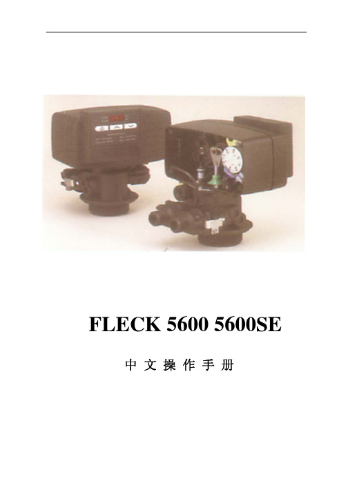
5600 & 5600型ECONOMINDER®多路阀操作手册本手册包含FLECK5600时间型过滤器(5600FT),软水器(5600ST);流量型软水器(5600SM)的调试操作说明5600产品概述FLECK全自动控制器以闻名于世的FLECK公司软化水技术为基础,它是将软水器的运行及再生的每一个步骤实现全自动控制,并采用时间、流量或感应器等方式来启动再生。
由于FLECK系列全自动软水设备控制系统技术成熟、操作简便、富来控制器采用的工程塑料和无铅黄铜阀体完全符合食品卫生要求,配以聚四氟乙烯(Teflon)涂层,活塞减小了阻力,延长了使用寿命,运行可靠。
FLECK系列全自动软水器可用于家用、工业锅炉、热交换器、宾馆饭店、食品工业、洗衣印染、医疗卫生等行业,该产品具有自动化程度高、交换容量大、结构紧凑、能耗低、省人工、无需日常保养等特点。
系统技术参数进口压力:0.2 Mpa-0.6 Mpa工作温度:2 ℃—50℃进水硬度:符合国家标准出水硬度:≤0.03mmol/L使用电源:220v/50Hz AC布置形式:单罐或双罐串联(二级软化时采用)再生方式:顺流再生操作程序:自动程序控制使用树脂:001×7强酸性阳离子交换树脂我公司将为用户提供完善的技术服务及售后服务。
第1页5600ST安装和启动程序软水器的安装,应根据制造商建议的入水口、出水口和排污口接管,且应符合相关管路规范。
在软水装置接通电源前1.将软水器控制阀手动转至工作位置,打开进出水口,使水流入树脂罐。
直到管路内空气排尽,当水流流出出水口时,关闭进出水口。
注:可手动旋转控制阀前部的旋钮将其拨至不同的再生位置,直到显示软水器处于所需位置。
2.将控制阀手动转至反洗位置,使水经排水口流出3或4分钟。
3.取下控制阀后盖板。
4.确保盐的用量按制造商的建议设置。
如有必要,按设置说明书设置盐的用量。
将控制阀手动转至盐水重注位置,使水填充至空气止回阀顶。
海川DW系列冰淇淋机说明书

二 安全警告
第一节 安全预防说明
◆触电 ·按照家用和工业用电标准,安装好接地装置。 ·使用符合安全标准的供电线路,包括符合安全标准规 定的接线方法和电器设备。 ·确保机器的供电线路装有短路和漏电保护装置。 ·在皮肤裸露、潮湿、戴有湿手套或穿着湿衣服时,禁 止接触带电的插头或开关。
◆ 机械损伤
·不要以任何方式接触机器的转动部分。(见图1)
400mm以上
300mm 图10
300mm
1接地保护线 2相线 3零线 图11
海川生态食品*中国软冰淇淋专家 7
DW系列软冰淇淋机使用说明书
·在室内空间较小的情况下,应为本机安装 流量不小于1000 3M /h的排气风扇。侧排风
的冰机不能并排放置。特殊情况需要并排放
输入三相电
截面积2.5mm²以上
裸机的运送和移动 ·无包装的机器只能用软质的吊带进行吊装或人工搬运(见图5和图6)。
图5
图6
艺智变频 低噪音 预冷 可触摸控制面板
6
DW系列软冰淇淋机使用说明书
本机可在平坦坚实的地面上推动行走,推动时请放开前脚轮的刹车装置。本机 前脚轮为万向轮,后脚轮为固定轮。允许上下坡的最大坡度为15 度。(见图7) ·在机器安装就位后,踩下前脚轮的制动踏板固定机器(见图8)
图12
图13
螺母 图14
·阀体安装完毕后,检查阀体密封圈与面板的紧密结合,四个螺母的预紧力 应均匀,阀塞上下运动应顺滑流畅。 ·将接料盒与接料架安装好,将接料架的定位孔对准接料台上的定位销,并 安装固定好,接料盒用于接取制糕时滴出的浆料。(见图15) ·将清洗干净的膨化管带有小孔的一端插入存料盆中的进料管内。(见图16) ·将机器蓝色接水盒插入机器右侧面板的方形孔内,直到接水盒完全放入。 注:安装完毕后通电,将急停开关向左扳动到ON状态,面板上红色指示灯应 亮,表头有数值显示,按下“清洗”按键,搅拌电机开始启动,表示机器附件 安装成功。
Philips 5600系列LED背光源智能电视产品说明书

请至以下互联网址注册产品以获得完整的信息服务快速使用指南使用产品前请阅读用户手册(具体操作详见操作导引)并请保留备用!5600系列LED背光源智能电视43PFF5657/T350PFF5657/T350PFF5659/T343PFF5659/T3产品外形根据型号不同会有所差异,请以实际机型为准!目录重要信息 3包装清单 5电池安装方式 6安装底座 7连接 8打开电视 12操作导引 13中国电子信息产品污染控制标识要求 15重要信息安全小心触电或发生火灾!• 切勿让电视机与雨或水接触。
切勿将液体容器(例如花瓶)放置在电视机旁边或上面。
如果将液体洒到了电视机表面或内部,请立即断开电视机的电源。
请与Philips 客户服务中心联系,对电视机进行检查后再行使用。
• 切勿将电视机、遥控器或电池放在明火或其它热源(包括直射的阳光)附近。
为避免火焰蔓延,请始终使蜡烛或其它明火远离电视机、遥控器和电池。
• 切勿向电视机上的通风槽或其它开口中插入任何物体。
• 旋转电视机时,请确保电源线不会绷紧。
电源线绷紧会使电源连接变松,进而产生火花。
小心短路或起火!• 切勿将遥控器或电池暴露在雨中、水中或过热的环境中。
• 请避免电源插头产生拉力。
松动的电源插头可能产生火花或者导致起火。
小心人身伤害或电视机损坏!• 需由两个人搬运重量超过25千克的电视机。
• 将电视机安装在机座上时,请仅使用提供的机座。
将机座牢固地固定到电视机上。
将电视机放在水平、平坦且可承受电视机和机座总重量的表面上。
• 采用壁挂方式安装电视时,请仅使用可承受电视机重量的壁挂安装托架。
将壁挂安装托架固定到可承受电视机和壁挂安装托架总重量的墙壁上。
TPV Display Technology(Xiamen)Co.,Ltd.对由于安装不当而造成的事故、人身伤害或损失不负任何责任。
小心伤害儿童!请遵循以下注意事项,以避免因电视机掉落而导致儿童受伤:• 切勿将电视机放在由可拉动的布或其它材料覆盖的表面上。
5600_5600SE_中文操作手册
b、 产水量设定 按动 Up 或 Down 键可以设定软水器再生前的产水量; c、 再生时间设定 按动 Extra Cycle 键,程序进入再生时间设定,通过按动 Up 或 Down
RINSE)、盐箱注水(BRINE REFILL)。
调试工作
1、 调整控制器到工作位置,让水流进树脂罐,当水流停止时,打开阀门以放尽罐中空气, 然后关闭;
2、 插上电源,观察是否工作; 3、 控制器时间设定 按动 Up 或 Down 键可调整时间,连续按住可连续调整; 4、 控制器简单编程(控制器时间非 12:01PM)
8、盐箱充水
硬水经控制器进水口,向下通过树脂 层,然后向下流过下布水器、中心管, 最后通过排水口流出。
硬水经控制器进水口,经过射流器、盐阀、 流量控制板给盐箱充水,同时硬水流过阀 体凹槽向下经过树脂层,被软化后进入布 水器、中心管,最后通过出水口流出。
5
5600 5600SE 中文操作手册
设备的安装和运行
(PRELIMINARY RINSE)、反洗(BACKWASH)、吸盐与慢洗(BRINE & SLOW RINSE)、快洗 (RAPID RINSE)、稳层清洗(SETTLING RINSE)、盐箱注水(BRINE TANK FILL)。
时间型
流量延时再生型
8
5600 5600SE 中文操作手册
调试工作
7
5600 5600SE 中文操作手册
FLECK5600 控制器(流量型/时间型) 调试步骤
准备工作和注意事项
a、 设备在调试及运行前应按厂家要求安装完毕进、出水、排污管道和阀门; b、 自来水、电源及排水沟准备就绪; c、 打开旁通阀,让自来水冲洗管道至出水变清,然后关闭阀门; d、 控制器手动再生旋钮只可顺时针旋转,相应位置分别为:工作(SERVICE)、预清洗
Sennheiser DW Office 单面无线 premium DECT 头戴耳机说明书
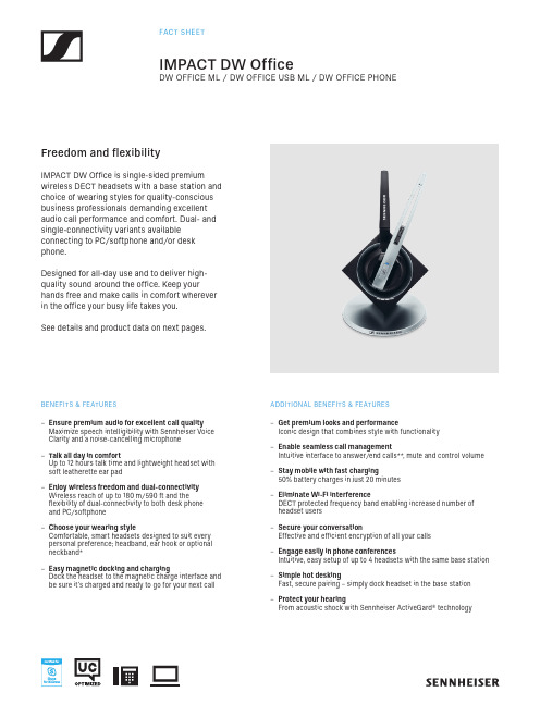
DW OFFICE ML / DW OFFICE USB ML / DW OFFICE PHONEIMPACT DW Office is single-sided premiumwireless DECT headsets with a base station and choice of wearing styles for quality-conscious business professionals demanding excellent audio call performance and comfort. Dual- and single-connectivity variants available connecting to PC/softphone and/or desk phone.Designed for all-day use and to deliver high-quality sound around the office. Keep yourhands free and make calls in comfort wherever in the office your busy life takes you.See details and product data on next pages.Freedom and flexibilityBENEFITS & FEATURES –Ensure premium audio for excellent call quality Maximize speech intelligibility with Sennheiser Voice Clarity and a noise-cancelling microphone –Talk all day in comfortUp to 12 hours talk time and lightweight headset with soft leatherette ear pad –Enjoy wireless freedom and dual-connectivity Wireless reach of up to 180 m/590 ft and theflexibility of dual-connectivity to both desk phone and PC/softphone –Choose your wearing styleComfortable, smart headsets designed to suit every personal preference; headband, ear hook or optional neckband* –Easy magnetic docking and chargingDock the headset to the magnetic charge interface and be sure it’s charged and ready to go for your next callADDITIONAL BENEFITS & FEATURES–Get premium looks and performanceIconic design that combines style with functionality–Enable seamless call managementIntuitive interface to answer/end calls**, mute and control volume –Stay mobile with fast charging50% battery charges in just 20 minutes–Eliminate Wi-Fi interferenceDECT protected frequency band enabling increased number of headset users –Secure your conversationEffective and efficient encryption of all your calls–Engage easily in phone conferencesIntuitive, easy setup of up to 4 headsets with the same base station –Simple hot deskingFast, secure pairing – simply dock headset in the base station –Protect your hearingFrom acoustic shock with Sennheiser ActiveGard® technologyProduct Data General DataProduct description IMPACT DW OFFICE ML: Wireless DECT headset, single-sided with base station. Dual con-nectivity to desk phone and PC/Softphone. UC optimized and Skype for Business Certified. IMPACT DW OFFICE USB ML: Wireless DECT headset, single-sided with base station. Single connectivity to PC/Softphone. UC optimized and Skype for Business Certified. IMPACT DW OFFICE PHONE: Wireless DECT headset, single-sided with base station. Single connectivity to desk phone.Wearing style Headband – single-sided and ear hook. Neckband available as accessory* Weight24 g / 0.86 oz (Ear hook version)50 g / 1.76 oz (Headband version)Ear pad sizeø 50 mm / 1.96 inPersonalization Yes, with nameplate on headsetAudioMicrophone Noise-cancelling microphone for speech clarityMicrophone frequency range150 Hz – 6.8 KHz (Wideband)300 Hz – 3.5 KHz (Narrowband)Mute microphone YesSpeaker type High-quality neodymium magnet speaker for outstanding audio quality Speaker frequency range150 Hz – 6.8 KHz (Wideband)300 Hz – 3.5 KHz (Narrowband)Technical DataDECT 1.880 to 1.900 MHz (EU, UK, AUS)1.920 to 1.930 MHz (US)GAP compatible Yes (Headset)Headset Connects to base stationBase station IMPACT DW OFFICE ML: Connects to desk phone and UC/Skype for BusinessIMPACT DW OFFICE USB ML: Connects to UC/Skype for BusinessIMPACT DW OFFICE PHONE: Connects to desk phoneHeadset Auto Link to Base Yes, can be activated on the base stationTemperature range Operational: +5 ⁰C to 45 ⁰C / +41 ⁰F to +113 ⁰FStorage: -20 ⁰C to 70 ⁰C / -4 ⁰F to +158 ⁰FBattery (Lithium Polymer)Exchangeable for service (see User manual)Range Line of sight: 180 m / 590 ftTypical office building: 55 m / 180 ftAutomatic power adjustment Yes (distance between headset and base)DW OFFICE ML / DW OFFICE USB ML / DW OFFICE PHONEDW OFFICE ML / DW OFFICE USB ML / DW OFFICE PHONEProduct DataTechnical DataTalk time Up to 8 hours (Wideband Mode)Up to 12 hours (Narrowband Mode)Standby time Up to 100 hoursAuto – headset OFF when out of range Yes, after 30 minutesCharge time0 – 50%: 20 minutes0 – 100%: 1 hourWarranty 2 yearsHearing ProtectionActiveGard® technology Protects users against acoustic injury caused by sudden sound burst on the lineEU***/AUS Limiter dependingon regional variantActivated by DIP switch, HeadSetup™ Pro and HeadSetup™ Pro ManagerContent of delivery IMPACT DW OFFICE ML IMPACT DW OFFICE USB ML IMPACT DW OFFICE PHONEWhat‘s in the box–Headset (with name plate forear hook and distance holder)–Base station–Power supply–USB cable–Audio phone cable–Headband (detachable)–Ear hook adapter withpre-mounted ear hook withleatherette sleeve andearbud size S–Extra earbuds size M and L–Name plate holder forheadband and name plateinstruction–Printed Quick Guide–Printed Safety Guide –Headset (with name plate forear hook and distance holder)–Base station–Power supply–USB cable–Headband (detachable)–Ear hook adapter withpre-mounted ear hook withleatherette sleeve and earbudsize S–Extra earbuds size M and L–Name plate holder forheadband and name plateinstruction–Printed Quick Guide–Printed Safety Guide–Headset (with name plate forear hook and distance holder)–Base station–Power supply–Audio phone cable–Headband (detachable)–Ear hook adapter withpre-mounted ear hook withleatherette sleeve and earbudsize S–Extra earbuds size M and L–Name plate holder forheadband and name plateinstruction–Printed Quick Guide–Printed Safety GuideSoftwareHeadSetup™ Pro (Freeware)Remote call control, firmware updates and settings /software PC Software (Freeware)For other relevant PC software, please check /software HeadSetup™ Pro Manager (Saas)Manage, update and configure your Sennheiser audio devices from one location/headsetup-pro-managerUC compatible Yes. For more information please go to /headsetcompatibility *Neckband available as accessory (Art. No. 506525)**Answer/end call requires EHS cable for desk phone and Sennheiser software for certain softphones***Noise at Work: The EU’s “Noise at Work Directive” (2003/10/EC) sets limits for two types of noisein the workplace: Acoustic burst and Sustained Noise.See more at /dw1536-2019Product OverviewConnects to Product name Order Name Art.no EAN Code UPC Code UnifiedCommunications Desk phone, PC/SoftphoneDW Office ML - EU DW Office ML - UK DW Office ML - AUS DW Office ML - US DW 10 ML – EU DW 10 ML – UK DW 10 ML – AUS DW 10 ML - US50445450445650445750445540 44155 05188 940 44155 05190 240 44155 05191 940 44155 05189 6 6 15104 18191 56 15104 18193 96 15104 18194 66 15104 18192 2UC optimized and Skype for Business CertifiedPC/SoftphoneDW Office USB ML- EU DW Office USB ML- UK DW Office USB ML- AUS DW 10 USB ML - EU DW 10 USB ML – UK DW 10 USB ML - AUS 504466 504468 504469 40 44155 05200 840 44155 05202 240 44155 05203 9 6 15104 18203 56 15104 18206 26 15104 18208 0UC optimized and Skype for Business CertifiedDesk phoneDW Office PHONE - EU DW Office PHONE - UK DW Office PHONE - AUSDW 10 PHONE – EU DW 10 PHONE – UK DW 10 PHONE - AUS 50443050443150443340 44155 05164 340 44155 05165 040 44155 05167 46 15104 18160 16 15104 18162 56 15104 18164 9For information about accessories and spare parts go to /dwDW OFFICE ML / DW OFFICE USB ML / DW OFFICE PHONE。
Econominder 5600 产品说明书

Manual del PropietarioPara preguntas o en caso de emergencia, favor comunicarse con el técnico de servicio local (preferiblemente con el que instaló el sistema).Este documento ha sido traducido por Pentair Mexico en Enero 2010. Veri que el número depieza del documento ya que éste varía de una región a otra.Características y Ventajas del Producto y Hoja de Especifi caciones del ProyectoIMPORTANTE: La información, especifi caciones e ilustraciones en este manual están basadas en la información más reciente disponible al momento de imprimirlo. El fabricante se reserva el derecho de hacer cambios sin previo aviso.Felicidades por la compra del nuevo sistema de trata-miento de agua con la válvula de control 5600. Estaadquisición brindará al usuario la tranquilidad de saberque este sistema le ofrecerá muchos años de uso ydisfrute de agua tratada.Características y Ventajas del Producto Diseño sencillo y resistente Cuerpo de la válvula resistente a la corrosión y a los rayos UV Económico (bajo consumo anual de energía)Elimina:ManchasTuberías obstruidasDepósitos de sarroMinerales disueltosEl Usuario Puede Disfrutar De:Mayor duración de los AparatosAhorra en energía (hasta 30% más)Menor uso de Detergente/Jabón/LimpiadorMás espuma de JabónPlatos, Toallas y Ropa más limpiosManos más suaves•••••••••••••Proyecto No. _____Modelo No. _____Prueba del Agua _____Capacidad por Unidad _____ Máxima _____ Por Regeneración _____Tamaño del Tanque de Minerales _____ Diámetro _____ Altura _____Tamaño del Tanque de Salmuera y Programación de Sal por Regeneración _____Especifi caciones de la Válvula de ControlTipo de Timer _____ Estándar _____ “L” _____ 7-días _____ 12-días _____ Medidor Estándar _____ Medidor Extendido _____Día/Hora de la Regeneración _____Control de Flujo de la Línea de Drenaje _____Capacidad de Rellenado de Salmuera _____Tamaño del Inyector _____ Programación del Medidor en Galones _____Programando la Hora del Día:Para programar la hora del día, oprimir el botón rojo y girar la rueda dentada de 24 horas hasta que la hora del día actual quede visible arriba de la flecha de la hora del día.Forzando una Regeneración Manual:Para regenerar manualmente la válvula, girar la perilla de regeneración manual a favor de las manecillas del reloj hasta donde dice “REGEN.”Modelo 5600Programando la Hora del Día:Para programar la hora del día, oprimir el botón rojo y girar la rueda dentada de 24 horas hasta que la hora del día actual quede visible arriba de la flecha de la hora del día.Programando la Rueda del Programa:Para programar la rueda de programación, sacar el disco de People (Personas) y girarlo de manera que el número de personas en la casa quede alineado con la dureza del agua en granos por galón de la casa. Soltar el disco y verificar que haya quedado bien alineado en la programación deseada. Esto proporciona una capacidad de reserva basada en 75 galones por persona.Forzando una Regeneración Manual:Para regenerar manualmente la válvula, girar la perilla de regeneración manual a favor de las manecillas del reloj hasta donde dice “REGEN.”NOTA: La unidad regenerará esta noche cuando la capacidad en galones llegue a cero.Modelo 5600 Econominder Programando la Hora del Día e Iniciando una Regeneración ManualPerilla de Regeneración ManualRueda dentada de 24 horasRueda de Programación (La válvula regenerará esta noche cuando la lengüeta salida quede alineada con el indicador rojo)Indicador RojoFlecha de la Hora del Día Botón Rojo para Programar la HoraPerilla de Regeneración Manual Rueda dentada de 24 horasBotón Rojo para Programar la Hora Disco del ProgramaGranos por GalónEscala de Dureza del AguaEtiqueta KEtiqueta de GalonesPunto BlancoIn Service (En Servicio):El agua dura entra a la unidad en la entrada de la válvula y fl uye hacia abajo a través del mineral en el tanque de minerales. El agua acondicionada entra al tubo central a través del distribuidor en la parte inferior, luego fl uye hacia arriba a través del tubo central, alrededor del pistón, y sale por la salida de la válvula.Preliminary Rinse (Enjuagado Preliminar):Enjuagado lento de la cama de resina. El agua fl uye hacia abajo a través de la cama de resina, hacia arriba por el distribuidor en la parte inferior y hacia afuera por el drenaje.Backwash (Retrolavado):El agua dura entra a la unidad por la válvula de entrada, fl uye a través del pistón, hacia abajo por el tubo central, a través del distribuidor en la parte inferior, y hacia arriba a través del mineral, alrededor del pistón y hacia afuera por la línea del drenaje.El agua pasa a través de la cama de resina en dirección opuesta al fl ujo normal, lo cual enjuaga la materia suspendida y la expulsa del tanque de resina. El retrolavado también hace que se afl oje la cama de resina, la cual se compacta durante el ciclo de suavizado (In Service - En Servicio).Brine/Slow Rinse (Suavizador Unicamente):El agua dura entra a la unidad por la válvula de entrada, fl uye hacia arriba al bastidor del inyector y hacia abajo a través de la boquilla y cuello para succionar salmuera del tanque de salmuera; la salmuera fl uye hacia abajo a través del mineral y entra al tubo central a través del distribuidor en la parte inferior y hacia afuera a través de la línea del drenaje.Los granos de resina se lavan con la concentrada solución de agua salada denominada salmuera. Dado que los granos de resina prefi eren los iones de calcio y magnesio, el enjuagado lento permite una abrumadora concentración de iones de sodio para vencer y expulsar los iones de calcio y magnesio de los granos de resina, los cuales posteriormente son descargados hacia el drenaje.Rapid Rinse (Enjuagado Rápido):Se enjuaga la cama de resina para remover el exceso de la solución de salmuera del tanque y entonces los granos de resina están listos nuevamente para producir agua suave.El agua dura entra a la unidad en la válvula de entrada, fl uye a través del pistón, hacia abajo al tubo central, a través del distribuidor en la parte inferior y hacia arriba a través del mineral, alrededor del pistón y sale por la línea del drenaje.Settling Rinse (Enjuagado de Sedimentación):Enjuagado lento de la cama de resina. El agua fl uye hacia abajo a través de la cama de resina, hacia arriba por el distribuidor en la parte inferior y hacia afuera al drenaje.Brine Tank Refi ll (Rellenado del Tanque de Salmuera) - Suavizador Unicamente:El agua dura entra a la unidad por la válvula de entrada, fl uye hacia arriba a través del bastidor del inyector, a través de la válvula de salmuera para rellenar el tanque de salmuera. Ahora la válvula está descargando agua suave a la casa. El agua cruda está rellenando el tanque de salmuera para hacer una solución de salmuera para la siguiente regeneración.Regeneration (Regeneración):Cuando la válvula está en Regeneración, el agua cruda se pasa a servicio hasta que se complete el Enjuagado Rápido.Descripciones de las Posiciones del Suavizador y del Filtro de la Válvula de ControlProblemaSolución La válvula de control no regenera.Revisar si hay energía eléctrica y verificar si launidad está conectada al tomacorriente. Si esto nofunciona, comunicarse con el técnico de servicio local(preferiblemente el que instaló el sistema).El agua no se siente ni se ve suave.Revisar el nivel de sal en el tanque de salmuera ymantener el nivel de sal por arriba del nivel del agua.Si el problema subsiste, comunicarse con el técnico deservicio unidad utiliza demasiada sal.Comunicarse con el técnico de servicio local.Pérdida de presión del agua.Fierro en el agua acondicionada.Excesiva agua en el tanque desalmuera.Otros problemas con elsuavizador de aguaFalla en el suministro de laenergía eléctrica Reprogramar la Hora del Día en caso de falla en el suministro de la energía eléctrica. Ver la página“Programando la Hora del Día”.Agregando Sal Asegurarse de que el nivel de sal en el tanque de salmuera esté siempre por arriba del nivel del agua.Presión del Agua Se requiere un rango de 20-125 psi de presión del agua para que la válvula de regeneración opere de manera efectiva.Instalación Eléctrica Se requiere un suministro ininterrumpido de corriente alterna (A/C). Asegurarse de que el suministro de voltaje sea compatible con la unidad antes de su instalación.Instalación Hidráulica Existente La instalación hidráulica existente deberá estar libre de acumulación de cal y de fierro. Reemplazar lastuberías que tengan mucha acumulación de cal y/o de fierro. Si la tubería está obstruida con fierro, instalar un filtro de hierro separado antes del suavizador de agua.Ubicación del Suavizador, del Drenaje y del Tanque de Salmuera Ubicar el suavizador cerca de un drenaje limpio que esté funcionando y conectar de acuerdo a los códigos hidráulicos locales. El tanque de salmuera deberá estar ubicado a menos de 20 pies (6 mts) del suavizador de agua. El drenaje no puede estar elevado más de 36 pulgs (91 cms) ni exceder los 20 pies (6 mts) de largo.Válvulas de Bypass Si la unidad no viene equipada con una, siempre hay que proveerse de una válvula de bypass para lainstalación. Si la válvula tiene fugas, girar el bypass de la posición de In Service (En Servicio) a la de Bypass.NOTA: Si la válvula continúa goteando después de poner el bypass en la posición de Bypass, cerrar la llave principal del agua y llamar INMEDIATAMENTE al técnico de servicio local (preferiblemente el que instaló el sistema).Lista de Verificación (“Check List”) Residencial en General y Solución de ProblemasModelos 5600 Time Clock y Econominder5600 Time Clock5600 EconominderModelos 5600 L-Style Econominder y Time Clock 5600 L-Style Econominder5600 L-Style Time ClockPara descargar el Manual deServicio para esta Válvula,favor visitar:P/N 42447-S Rev. A。
晶微抗力表5600说明书
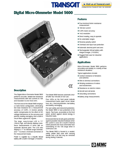
Digital Micro-Ohmmeter Model 5600 DescriptionThe Digital Micro-Ohmmeter Model 5600 performs accurate, reliable low resistance measurements with test currents to 10A and resolution to one micro-ohm.The front end of the Model 5600 employs a 4-wire Kelvin configuration, eliminating test lead resistance for a measurement accuracy of 0.25%. A reverse polarity switch compensates for the effect of DC voltage interference on the accuracy and permits reading averaging. And a built-in circuit filters against AC signals.The large, easy-to-read LCD is 71" (18mm) high, and directly displays resis-tance measurements in ohms with an a u t o m a t i c decimal point. The LCD also displays a “1” to indicate range overload, and “–” to show a reversed connection of the measurement leads.Power is supplied by a long-life NiCad battery with a built-in recharger (110/220V). The Model 5600 features automatic shut-o f f after four minutes of non-use.Four LEDs on the front panel indicatemeasurement faults (open circuit, blownfuse, etc.), thermal protection, low batteryand battery recharging.For user safety and instrument protection,the Model 5600 is fuse protected at theinputs. Two fuses, accessible on the frontpanel, protect against stored energy ininductive loads.Enhanced internal circuitry gives protectionagainst possible inductive kickback whenthe current is shut off. A built-in thermalswitch provents the micro-ohmmeter fromoverheating on the 10A range when incontinuous use.The Model 5600 is housed in a sealed,safety yellow field case with carryinghandle and a lid that may be removedduring testing if desired.Featuresx Four-terminal Kelvin resistancem e a s u r e m e n tx10A test currentx0.25% basic accuracyx1mΩ resolutionx Direct reading, easy to operatex Six selectable rangesx Reverse polarity switchx Overload and input fuse protectionx Automatic decimal point and zerox Rechargeable NiCad battery withintegral charger (110/220V)x Rugged field case for industriala p p l i c a t i o n sApplicationsMicro-Ohmmeter Model 5600 performsaccurately and reliably in a variety of flowresistance situations.Typical applications include:x Contact resistance of breakersand switchesx Wire to terminal connectionsx Winding resistance of motorsand transformersx Resistance on electric motorsx Aircraft and rail bondsx Grounding connectionsxBattery strap measurementsORDERING INFORMATION CATALOG NO.M i c r o-Ohmmeter Model 5600. . . . . . . . . . . . . . . . . . . . . . . . . . . . . . . . . . . . . . . . . . . . . . . . . . . . . . . . . . . . . . . C a t .# 1431.01includes 110V battery, AC supply cord and user manualAccessories and ReplacementsKelvin probes, set of two, on 10-ft color-coded leads with banana plug terminations. . . . . . . . . . . . . . . . . . . . . . . . Cat. #1017.82Kelvin clips, 1A, set of two, on 10-ft color-coded leads with spade lug terminations . . . . . . . . . . . . . . . . . . . . . . . . Cat. #1017.83Kelvin clips, 10A, set of two, on 10-ft color-coded leads with spade lug terminations . . . . . . . . . . . . . . . . . . . . . . . Cat. #1017.84Kelvin probes, 10A, 20-ft spring loaded. . . . . . . . . . . . . . . . . . . . . . . . . . . . . . . . . . . . . . . . . . . . . . . . . . . . . . . . . . Cat. #2118.52SpecificationsE L E C T R I C A L M E C H A N I C A L C o n n e c t i o n s :T erminals accept 4mm banana plugs or 6 mm (min) spade lugs D i s p l a y :2000 count, 7-segment LCD Operating Te m p e r a t u r e :14° to 131°F (-10° to 55°C)S t o r a ge Te m p e r a t u r e :-4° to 131°F (-20° to 55°C)D i m e n s i o n s :15.35 x 10.24 x 9.84” (390 x 260 x 250mm)We i g h t :17 lbs 10 oz (8 kg approx)C a s e :Fiberglass-charged polycarbonate,with handle and removable lid, watertight to IP534 (lid closed), IP520 (lid open)C o l o r s :Case: safety yellow; Front panel: g r a yS A F E T Y CE MarkE l e c t r i c a l :IEC 348 Class II; IEC 38,Supply voltageE l e c t r o m a g n e t i c :IEC 801-2, Electrostatic discharge IEC 801-3, Electromagnetic Fields IEC 801-5, Electrical shocks M e c h a n i c a l /e n v i r o n m e n t a l :IEC 529, Protection Index (IP)IEC 68.2.6, Vi b r a t i o n s IEC 68.22.27, Shocks IEC 68.2.29, ShakeIEC 68.2.31, Knock over IEC 68.2.32, Drop test Case Material:U L 94, Case materialDielectric Te s t :IEC 348, 1500V 60Hz (input terminals);3000V 60Hz (power supply)Overload Input Pro t e c t i o n :380V r m s F u s e s :Two high-interrupting capacity 8AA c c u r a c y :2000µΩ ra n g e :0.25% typical, 0.5% max ± 2 digits 20–200–2000m Ω, 20–200Ω ra n g e s :0.25% typical, 0.5% max ± 1 digit Power Supply :Rechargeable 6V , 7Ah NiCad battery;built-in 110V/220V (47-450Hz) charger;auto shutoff after 4 minutes non-use B a t t e r y Life (Ty p i c a l ):200µΩ ra n g e :200 to 300 8-second measurements 20–200m Ω ra n g e s :900 30-second measurements (approx.)2000m Ω, 20-200Ω ra n g e s :5000 30-second measurements (approx.)Operating V o l t a ge :4.5 – 7V D CR e c h a r ge T i m e :14 hours from full discharge (approx.)R a n g e s 2000µΩ20m Ω200m Ω2000m Ω20Ω200ΩD i s p l a y 199919.99199.9199919.99199.9R e s o l u t i o n 1µΩ10µΩ100µΩ1m Ω10m Ω100m ΩTest Current10A1A1A 100m A 10m A 10m A Leadt e r m i n a l sT h e r m a l protection indicator Measurementcurrent fault indicator Batteryindication lights Line cord input socketfor battery rechargingRotary selector switchInput fuse holders Polarity inverter switchL C D O n /o f f power button。
DWE系列动态检重秤使用手册20100325(1)

DWE_UM01_1003_CN DWE系列动态检重秤用户使用手册版本1003德康达(北京)工业自动化技术有限公司DWE 系列动态检重秤 用户使用手册DWE_UM01_0905_CN21 概述 ................................................................................................................................................. 3 1.1 保修原则 .......................................................................................................................................... 3 1.2 使用目的 .......................................................................................................................................... 4 1.3 安全说明 .......................................................................................................................................... 4 1.4 认证 ................................................................................................................................................. 4 1.5 最大允许误差 ................................................................................................................................... 4 1.5.1 OIML R76 (静态称重标准) .......................................................................................................... 4 1.5.2 OIML R 51 (动态称重标准) ......................................................................................................... 5 1.6 版本更新历史 ................................................................................................................................... 5 2 动态称重 .......................................................................................................................................... 6 2.1 连续称重工作方式 ............................................................................................................................ 7 2.2 连续称重的重量测定 ........................................................................................................................ 8 2.3 连续称重的系统要求 ........................................................................................................................ 9 2.4 称重货物的间距要求 ........................................................................................................................ 9 3 动态检重秤的结构和部件 .............................................................................................................. 10 3.1 动态检重秤的结构 .......................................................................................................................... 10 3.2 不带进料传送带和带有进料传送带的动态检重秤的可选方案 ......................................................... 11 3.3 称重终端 ........................................................................................................................................ 11 3.3.1 连续动态运行称重的重要参数 ........................................................................................................ 11 3.3.2 重要的称重参数设置 ...................................................................................................................... 12 3.4 称重传感器..................................................................................................................................... 13 3.5 控制单元 ........................................................................................................................................ 13 3.5.1 功能描述和流程描述 ...................................................................................................................... 13 3.5.2 DWE 和电气控制系统之间的信号交换 ........................................................................................... 13 3.5.3 开关柜 ............................................................................................................................................ 14 4 数据和尺寸 .................................................................................................................................... 15 4.1 技术参数 ........................................................................................................................................ 15 4.2 尺寸,单位mm ............................................................................................................................. 16 5 安装和调试 .................................................................................................................................... 18 5.1 DWE 安装说明 ............................................................................................................................... 18 5.2 DWE 的电气连接 ........................................................................................................................... 18 5.3 DWE 的调试 .................................................................................................................................. 18 5.4 皮带输送机的操作说明和维护说明 ................................................................................................ 19 5.4.1 调试 ............................................................................................................................................... 19 5.4.2 安全规定 ........................................................................................................................................ 20 5.4.3 环境影响 ........................................................................................................................................ 20 5.4.4 运输和搬运..................................................................................................................................... 20 5.4.5 保养说明 ........................................................................................................................................ 20 5.4.6 张紧-与校正图 ................................................................................................................................ 21 5.4.6.1 在使用套式传动装置或键条-或齿形皮带驱动装置时对驱动卷筒进行校正 .................................... 21 6 故障信息、原因及处理 .................................................................................................................. 22 7 检查,维护和保养 . (23)DWE 系列动态检重秤 用户使用手册DWE_UM01_0905_CN31 概述DWE 动态检重秤,是一台具有世界领先的动态称重技术的高质量的称重设备。
LG 50LN5600 LED电视说明书
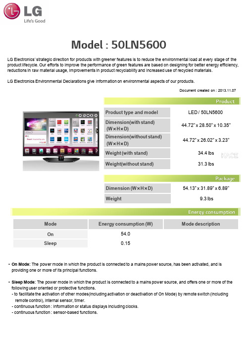
Model : 50LN5600 Product type and model LED / 50LN5600Dimension(with stand)(W ×H ×D)44.72" x 28.50" x 10.35"Dimension(without stand)(W ×H ×D)44.72" x 26.02" x 3.23"Weight (with stand)34.4 lbs Weight(without stand)31.3 lbsLG Electronics’ strategic direction for products with greener features is to reduce the environmental load at every stage of the product lifecycle. Our efforts to improve the performance of green features are based on designing for better energy efficiency,reductions in raw material usage, improvements in product recyclability and increased use of recycled materials.LG Electronics Environmental Declarations give information on environmental aspects of our products.ModeEnergy consumption (W)Mode descriptionOn54.0Sleep 0.15Dimension (W ×H ×D)54.13" x 31.89" x 6.89"Weight 9.3 lbsDocument created on : 2013.11.07•On Mode:The power mode in which the product is connected to a mains power source, has been activated, and is providing one or more of its principal functions.•Sleep Mode:The power mode in which the product is connected to a mains power source, and offers one or more of the following user oriented or protective functions.-to facilitate the activation of other modes(including activation or deactivation of On Mode) by remote switch (including remote control), internal sensor, timer.-continuous function : information or status displays including clocks.-continuous function : sensor-based functions.This product complies with the below mentioned directives and regulations.EU RoHS DirectiveDirective 2011/65/ECEU REACH RegulationRegulation 1907/2006/ECOtherOzone Depleting Substances as banned in the Montreal Protocol>> Further information on the LG Electronics hazardous substance management system, hazardous substance phase out program and REACH compliance can be found at :/global/sustainability/environment/management-of-hazardous-substances/details-of-hazardous-substances1)Mechanical plastics parts heavier than 25g are labeled with material codes in accordance with ISO 11469 and ISO 1043-1~4 to facilitate plastic recycling.Recycling in the EU: LG Electronics has fulfilled the WEEE directive demands in all EU countries. The following are recycling firms to which LG Electronics has subscribed at/global/sustainability/environment/take-back-recycling/global-network-europe1)Recycling in the US and Canada: LG Electronics complies with electronic waste regulations in each state in the US and in provinces of Canada in which it does business. In addition, LG Electronics has voluntary collection sites and holds periodic collection events even in states without e-waste laws in place. LG Electronics is also a proud sponsor of Keep America Beautiful’s Great American Cleanup. The following are recycling firms to which LG Electronics has subscribed at/global/sustainability/environment/take-back-recycling/global-network-north-america1) Recycling in other regions: LG Electronics also operates take-back and recycling programs for unwanted products in countries where local take-back regulations do not exits. Customers are advised to contact the local LG service center for further information.•The product packaging complies with the below mentioned directives and regulations :EU Packaging Directive 94/62/ECOzone Depleting Substances as banned in the Montreal Protocol•LG Electronics has phased out the use of Polyvinylchloride (PVC) from this product packaging.•Plastic packaging material is marked in accordance with ISO 11469 and ISO 1043-1 to 4 or the relative regulation in Korea, Japan and China.1) This link is to a website outside the control of LG Electronics USA (“LGEUS”) which is intended for international viewing.The information contained in this website may not apply in the U.S.You should refer to and only rely on the marketing andinformational materials distributed by LGEUS in the United States.This website may also contain “forward -looking statements;” that is, statements related to future events.Forward-looking statements by their nature address matters that are, to different degrees, uncertain.These uncertainties may cause LG’s actual future results to be materially different from those expressed in the forward-looking statements on the website. Label/Certification Category Name OrganizationEnergy ENERGY STARMost Efficient 2013Environmental Protection Agency (EPA)•Electronic devices should not be treated as household wastes; check with your local and state solid waste officials or your LGE service center for availability of recycling in your area.•Please separate the packaging material according to responsible waste disposal practices and sort forsound recycling; contact your local LGE service center or check local regulations for correct disposal ofhousehold electronics.•This product provides the user guide printed with soy ink for reducing emissions of VOCs(Volatile Organic Compounds) and reduction of metal pigments. To download a copy of 50LN5600user guide, visit/us/support 1)•Further Environmental information is presented in LG Electronics’ Sustainability Report (PDF form),available online at :/global/sustainability/communications/sustainability-reports.jsp 1)•If you have questions, Please contact *****************。
Sennheiser DW Wireless Series 电话头戴片说明书

Experience Sennheiser soundEE choose Sennheiser becauseonly the best will doEE boosts performanceand service levels with Sennheiser DW Wireless Series headsetsCompany: EE UKWebsite: Customer size: 2,400Industry: Telecommunications Product: Sennheiser DW Wireless Series headsets (DW Office, DW Pro1, DW Pro 2)Number of units: 1,000+ headsets About EE: EE is part of the UK’s largest communications company, providing mobile and fixed-broadband communication services to more than 27 million customers. EE’s priority is to guide its customers in the digital world, bringing them services that are ever more reliable and innovative. Backed by a world-class quality network, the people of EE are committed to bringing their customers the very best customer experience.The challenge: EE needed a wireless headset solution to provide their customer service agents with greater mobility and increased call efficiency. The solution also had to be future-proof and compatible with the company’s new wideband solution.As the UK’s fastest growing mobile telecommunications company, EE believe in giving their employees the best tools to excel. When updating their call centre headsets in North Tyneside, Plymouth and Darlington, they turned to Sennheiser to deliver a wireless solution that bot improved performance and gave customers better service.“R educed hold time and decreased call time gives us fantastic savings“In their own wordsSee the case storyand hear how EEexperienced Sennheiser/eecase▲Quality countsThe sense of being given quality tools to work with had a surprising effect on the way the equipment was handled: Before, headsets were just left around on the desks, but now they are being put away at night, cleaned and well looked after.“When I saw Sennheiser on the box,I knew it was going to be good: I’m also aDJ and know the brand already. It was niceto have that logo on my work headset too.On previous headsets I got a lot ofbackground noise – the call centre is quiteloud. But with this set, all I hear is what’sgoing on in the call. I don’t get any of thebackground noise that you get withnormal headsets.The headset is extremely comfortable,it’s got very good padding. I don’t reallynotice the headband – it’s like my DJheadphones – that level of comfort.When I’ve been using headsets in thepast, customers often said they couldn’thear what was being said. They’d also bepicking up a lot of background noise fromother call agents. It’s nice with this newheadset that the speech on them is veryclear – which obviously saves a lot oftime on the call.Because I know the brand, I knew thequality of the headsets was going to bereally good and they weren’t one of thecheaper headsets: I find I look after thema lot better and I actually feel a bit proudabout wearing them.”“ With these new headsets,speech is very clear – which obviously saves a lotof time on the call.David TaitCustomer Service AgentEE UK“Users chooseThe range of headsets, from the monaural DW Office and DW Pro 1 to the binaural DW Pro 2, meant that users found a solution which best suited their individual working styles and the varying noise level at their work environments.“After trying out a variety of differentheadsets, the DW series got the mostpositive feedback from our frontline stafffor their design, range and sound quality.We’ve seen some huge improvementsin terms of hitting our targets andperformance goals: Reduced hold time forcustomers and overall decreased call timegive us fantastic savings. We’ve also seenan improvement in our service levels.Features like ActiveGard™, give us thepeace of mind that we are doing everythingpossible to protect our staff against acousticshock. In a workforce of this size, avoidingsick days makes a real difference. The sturdybuild also means we’ve had hardly anybreakages, which had previously been amajor problem. You really get what youpay for. Overall we couldn’t be more pleasedwith the products and services providedby Sennheiser. They have been first class.The support we have received in setting upthese products in our various contactcentres, has really been superb. The wholeexperience has been professional, with agreat understanding of how these headsetscan help us deliver the very best customerexperience.”“W e’ve seen hugeimprovements in hitting ourperformance goals.“Paul AndersonImplementation ManagerEE UKPerformance firstEE have high standards, and one simple aim when it comes to people:“To attract the highest-calibre, most ambitious and most innovative employees, and then give them everything they need to perform their socks off.”“As an operations manager, it’s reallykey that our staff has the best toolsavailable. Our staff are very aware thatthe kit we’ve given them is pretty muchtop of the line, and they know thelevel of investment we’ve given them.They’re very proud to have that.It took us a little while to getused to seeing people walking aroundthe building apparently talking tothemselves. Then they’d turn aroundwith a single-sided headset on, and you’drealize they were having a conversationwith a customer.It just seems like a much more relaxedenvironment when they can do that.Obviously people that work in thisindustry like to see the newest gear, andthese are quite modern looking. Agentswho don’t have these pieces of equipmentare curious and want to see how they work.Team managers can now talk to acustomer or monitor calls simply bytapping the same box – that was new toagents and generated quite a lot ofconversations. It was good to see on thatnerdish level, that people wanted toknow it and try it.”“A s an operations manager,it’s really key that ourstaff get the best tools thatare available.“Peter Davis-McCabeOperations ManagerEE UKSennheiser is one of the world’s leadingmanufacturers of headphones, microphones,wireless transmission systems and high-qualityheadsets for both business and entertainment.Drawing on the electro acoustics expertise ofSennheiser and the leading hearing healthcarespecialist William Demant, SennheiserCommunication’s wireless and wired headsetsfor contact centers, offices and UnifiedCommunications professionals are the resultof Sennheiser’s and William Demant’s jointleadership in sound quality, design, wearingcomfort and hearing protection.Sennheiser Communications A/SLangager 6 · DK-2680 Solrød Strand · Denmark Experience SennheiserPerfection is always relative: Users have different expectations from their headsets depending on their needs. For professional users, that need is to communicate as effectively as possible.With Sennheiser’s range of headsets, the combination of exceptional HD sound, quality design and build – and a focus on real life usability - give the best performance possible in busy offices, contact centers and Unified Communications environments.Please visit us at: /cco。