倍加福 超声波传感器 UC2000-30GM-E6R2-V15 手册
倍加福液位计UB4000-F42-I-V15

零线模式
᱖ذ pause
" 零线模式 " 中指定测量边界 A1 为 0,测量边界 A2 决定输出特性。 按下 A1 键 2 秒钟保存所选的输出模式,完成参数设定并确保接近开关返回标准模 式。再短按 A1 键将开始进行步骤 2 (声锥宽度的选择) 。 步骤 2,超声波声锥宽度的选择 在近距离内,通过步骤 2,超声波声锥的宽度可以根据不同的应用进行调整。 首先显示当前声锥的宽度。 所有可选的声锥宽度可以通过连续短按 A2 键进行选择, 每次按键后红色 LED 的闪烁序列将会发生变化,从而显示不同的声锥宽度。 声锥宽度
Release date: releasedate Issue date: 2007-10-09 134003_CN.xml
红色 LED 的闪烁序列
᱖ذ pause
A2 键
小声锥
中等声锥
pause ᱖ذ
大声锥
pause ᱖ذ
按下 A1 键 2 秒钟保存所选的声锥形状,完成参数设定并确保接近开关返回标准模 式。短按 A1 键将返回步骤 1 (输出功能的设定) 。 如果在进入参数设定模式 5 分钟后没有完成设定,接近开关将不更改任何设置并退 出设定模式。
上升模式
ူইఇ๕ A1 ଭ၍ఇ๕
ఇెଉݛ๕
ப൶
ణՔྷݔ ฉืఇ๕ A1 A2
A2
绿色 LED 的闪烁序列
᱖ذ pause
A2 键
A1 = 0 A2
附件
pause ᱖ذ
下降模式
MH 04-3505 安装附件 MHW 11 安装附件 DA5-IU-2K-V 显示器 V15-G-2M-PVC 电缆连接器 V15-W-2M-PVC 电缆连接器
Pepperl+Fuchs UC4000-30GM-E6R2-V15 超音波传感器产品说明书
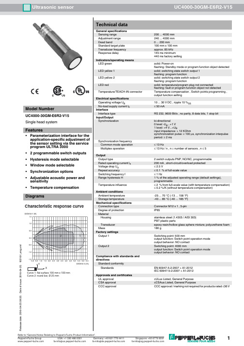
Ultrasonic sensorUC4000-30GM-E6R2-V15R e l e a s e d a t e : 2016-04-25 09:35D a t e o f i s s u e : 2016-04-25102161_e n g .x m lDimensionsElectrical ConnectionPinoutTemperature probeCoded plug52225108ø40M30x1.527.536LED+ UB- UB12435(BN)(WH)(BK)(BU)(GY)Standard symbol/Connection:(version E6, pnp)Switch output 1Switch output 2Sync.Core colors in accordance with EN 60947-5-2.134521 BN2 WH3 BU4 BK 5GYWire colors in accordance with EN 60947-5-2(brown)(white)(blue)(black)(gray)Additional InformationSwitch point 1Switch point 2A 1 (N.O.)Switch output 1A 2 (N.O.)Switch output 2A 1 (N.C.)Switch output 1A2 (N.C.)Switch output 2A 1 (N.O.)Switch output 1A2 (N.C.)Switch output 2A 1 (N.O.)Switch output 1A2 (N.C.)Switch output 21. Switch point modeWhen A1 < A2, both switch outputs are activated as N.O. contacts.2. Window modeT o exchange the switching distances is of no effect. 3. Latching modeT o exchange the switching distances is of no effect. When A1 > A2, both switch outputs are activated as N.C. contacts. Possible operating modesR e l e a s e d a t e : 2016-04-25 09:35D a t e o f i s s u e : 2016-04-25102161_e n g .x m lDescription of Sensor FunctionsProgramming procedureThe sensor features 2 programmable switch outputs with programmable switch points. Programming the switch points and the operating mode is done either via the sensors RS232 interface and the ULTRA 3000 software (see the ULTRA 3000 software description) or by means of the programming plug at the sensors rear end which is described here.Programming switch points 1 and 21.Disconnect supply voltage2.Remove the programming plug to activate program mode.3.Reconnect supply voltage (Reset)4.Place the target at the desired switch point position for A15.Momentarily insert the programming plug in position A1 and then remove. This will program the switch point A1.6.Place the target at the desired switch point position for A27.Momentarily insert the programming plug in position A2 and then remove. This will program the switch point A2.Notes:•Removing the programming plug saves the new switch point position into the device memory.•The programming status is indicated by the LED. A flashing green LED indicates that the target is detected; a flashing red LED indicates that no target is detected.Programming the operation modeIf the program mode is still activated, continue at number 4. If not, activate program mode by performing the sequence numbers 1 to 3.1.Disconnect supply voltage2.Remove the programming plug to activate program mode.3.Reconnect supply voltage (Reset)4.Insert the programming plug in position E2/E3. By removing and reinserting the plug, the user can toggle through the three different modes of operation. The selected mode is indicated by the LEDs as shown below:•Switch point mode, LED A1 flashes •Window mode, LED A2 flashes•Latching mode, LEDs A1 and A2 flash5.Once the desired mode is selected, insert the programming plug in position T. This completes the programming procedure and saves the switch points and mode of operation.6.The sensor now operates in normal mode.Note:The programming plug also functions as the temperature compensation. If the programming plug has not been inserted in the T position within 5minutes, the sensor will return to normal operating mode with the latest saved values, without temperature compensation.Factory settingsSee technical data.DisplayThe sensor provides LEDs to indicate various conditions.Mounting flange, 30 mmBF 5-30Universal mounting bracket for cylindrical sensors with a diameter of 5...30mm UC-30GM-PROGULTRA3000Software for ultrasonic sensors, comfort line UC-30GM-R2V15-G-2M-PVCFemale cordset, M12, 5-pin, PVC cableGreen LEDRed LED Yellow LED A1Yellow LED A2During Normal Operation - Temperature compensated- with removed programming plug Interference (e.g. compressed air)On Off OffOff On FlashingSwitching state A1Switching state A1remains in previ-ous state Switching state A2Switching state A2remains in previ-ous stateDuring Sensor Programming Switch point A1: Object detected No object detected Switch Point A2: Object detected No object detected Operation mode: Switch point mode Window mode Latching mode Flashing Off Flashing Off On On On Off Flashing Off Flashing Off Off Off Flashing Flashing Off Off Flashing Off Flashing Off Off Flashing Flashing Off Flashing Flashing StandbyFlashingOffprevious stateprevious stateR e l e a s e d a t e : 2016-04-25 09:35D a t e o f i s s u e : 2016-04-25102161_e n g .x m lSynchronizationThis sensor features a synchronization input for suppressing ultrasonic mutual interference ("cross talk"). If this input is not connected, the sensor will operate using internally generated clock pulses. It can be synchronized by applying an external square wave. The pulse duration must be ≥100 µs. Each falling edge of the synchronization pulse triggers transmission of a single ultrasonic pulse. If the synchronization signal remains low for ≥ 1 second, the sensor will revert to normal operating mode. Normal operating mode can also be activated by opening the signal connection to the synchronization input (see note below).If the synchronization input goes to a high level for > 1 second, the sensor will switch to standby mode, indicated by the green LED. In this mode,the outputs will remain in the last valid output state.Note:If the option for synchronization is not used, the synchronization input has to be connected to ground (0 V) or the sensor must be operated via a V1 cordset (4-pin).The synchronization function cannot be activated during programming mode and vice versa.The following synchronization modes are possible:1.Several sensors (max. number see technical data) can be synchronized together by interconnecting their respective synchronization inputs.In this case, each sensor alternately transmits ultrasonic pulses in a self multiplexing mode. No two sensors will transmit pulses at the same time (see note below).2.Multiple sensors can be controlled by the same external synchronization signal. In this mode the sensors are triggered in parallel and are syn-chronized by a common external synchronization pulse.3.A separate synchronization pulse can be sent to each individual sensor. In this mode the sensors operate in external multiplex mode (see note below).4.A high level (+U B ) on the synchronization input switches the sensor to standby mode.Note:Sensor response times will increase proportionally to the number of sensors that are in the synchronization string. This is a result of the multiplex-ing of the ultrasonic transmit and receive signal and the resulting increase in the measurement cycle time.Note on communication with the UC-30GM-R2 interface cableThe UC-30GM-R2 interface cable allows for communication with the ultrasonic sensor using ULTRA3000 software. The cable creates a connection between a PC RS-232 interface and the programming plug socket on the sensor. When connecting to the sensor, make certain the plug is lined up correctly; otherwise no communication will be possible. The key of the cable’splug must be aligned to the groove of the socket on the sensor (not with the arrow symbol on the sensor).Programmable parameters with the ULTRA3000 software•Switch point 1 and 2•NO/NC function•Operation mode •Sonic speed•Temperature offset (The inherent temperature-rise of the sensor can be considered in the temperature compensation)•Expansion of the unusable area (for suppression of unusable area echoes)•Reduction of the detection range (for suppression of remote range echoes)•Time of measuring cycle•Acoustic power (interference of the burst duration)•Sensitivity•Behaviour of the sensor in case of echo loss •Behaviour of the sensor in case of a fault•Average formation via an allowed number of measuring cycles •On/off-delay•Switching hysteresis•Selection of the parameter set, RS 232 or manually Note:When connected to a PC and running the ULTRA3000 software, the sensor can act as a long term data logger as well.。
1倍加福光电传感器 中文

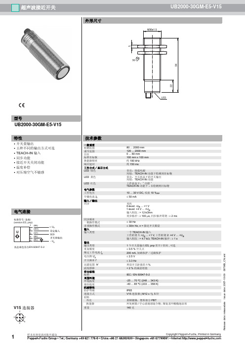
外形尺寸
LS610-DA-P/F1
97.5 90
36
81
171
170
Bus IN M12 x1, 5-䩜䖲༈ B-coded
Bus OUT/㒜ッ⬉䰏 M12 x1, 5-ᄨ䖲༈ B-coded
⬉⑤ M12 x1, 4-䩜䖲༈
型号
LS610-DA-P/F1
光通讯
接口 1) M12, 4 针连接头 (A-Code); 2) M12, 5 针连接头 (B-coded); 3) M12, 5 孔连接头 (Bcoded)
光通讯
技术参数
一般说明 有效检测范围
0 ... 120 m
极限检测范围 认证
140 m CE
光源特性 光斑直径 发散角
红外光,调制光 2 m (100 m 处) 1.1 º
极限环境光强 指示灯 / 动作说明
> 10000 Lux
状态指示 参数设定 电气特性 工作电压 通讯速率 载波频率 空载电流 通讯接口 通讯接口 输入
柱状指示条、接收发射状态、通讯速率指示等,详见操作手册 2 操作键进行参数设定
18 ... 30 V DC
93.75, 187.5,(350), 500, 1500 kBit/s ;操作键设定
F1=8.25 MHz
I0
200 mA
PROFIBUS,电气隔离
控制输入 输出
操作键控制:内置上拉电阻,接 (0 V) 锁住操作键
功能
LS610-DA-P 主要用于 PROFIBUS 网络中的串行数据通讯,最大通讯速率可达 1500 kbit/s,最远通讯距离可达 240 m。使用中需 要选择一对 LS610-DA-P,其中一个载波频率为 F1,另一个载波频率为 F2。 数据通讯
德国倍加福超声波传感器UC6000-30GM
传感器有一个同步输入端可以抑制传感器之间的相互影响。如果同步输入端不接, 传感器则根据内部产生的时钟频率工作。在传感器的同步输入端上加载一个脉冲宽 度大于 100 μs 的方波脉冲,可以实现同步工作。同步输入端上的同步脉冲启动一个 测量周期,测量周期由同步脉冲的下降沿触发。持续时间大于 1 s 的低电平或者同 步输入端开路,传感器则根据自身内部频率工作。
3
ḋᴀݙᆍᬍᯊᘩϡ䗮ⶹ
Copyright Pepperl+Fuchs, Printed in Germany
超声波传感器
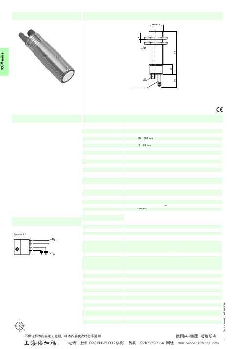
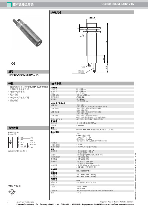
外形尺寸
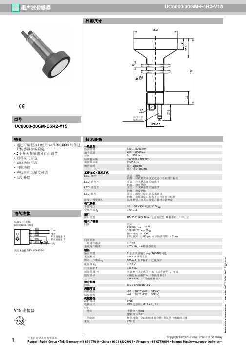
UC6000-30GM-E6R2-V15
ø73
19 32.5 112
5
36
27.5 22
型号
UC6000-30GM-E6R2-V15
特性
• 通过可编程接口使用 ULTRA 3000 软件进 行传感器参数设定
• 2 个开关量输出可自由调节 • 迟滞模式可选 • 窗口功能可选 • 同步功能 • 声功率和灵敏度可调 • 温度补偿
ມ-LED ୴/ࢤ
LED !!!!ࣜ
E2
E3
A1
A2
ਸ࠲!1
"ཚ"ۉ/߅ඡ
ਸ࠲!2
RS 232-থ੨
ӈ֣
࿒܈/Պ֭ײཀྵ
(ᆯথ੨ۉમ
UC-30GM-R2 থPC)
41
1: TXD 2: RXD 3: փᆩ 4: ں
32
V15-֭ཀྵ (M12x1)
LED-ش੨
ਸ࠲ݛ๕
1. ਸ࠲ఇ๕ ړA1 < A2 ้Ljघऄྺਸ
A 1 (N.O.) ਸ࠲ 1
应用手册 – 超声波和电容式传感器说明书

应用手册工程和农用机械超声波和 电感式传感器超声波和接近传感器产品目录Cod. CAT3E001269501应用手册 – 超声波和电容式传感器 - 中文版 – 2013年01月意 大 利 传 感 器 技 术2/3应用手册超声波和电感式圆柱形和立方形产品系列超声波传感器:M18带示教按钮、 M18短外壳、M30电感式传感器:微型、标准型、DECOUT ®、IP68、立方形超声波和电感式圆柱形和立方形产品特点特殊逻辑输出:NPN+PNP / NO-NC 可选 (电感式传感器)特殊工作电压 10...50直流电压 配备电池电源供电(电感式传感器) 耐低温特殊电缆(可耐-40°C ) 多种产品外壳满足用户需要模拟量输出:0-10 V 和4-20 mA (超声波传感器)工作电压 12...30直流电压 配备电池供电(M30超声波传感器)产品认证防护等级IP67, IP684/5应用手册超声波和电感式圆柱形和立方形摊铺机内沥青料位及路面沥青摊铺厚度检测必须使用可以在室外作业,并能从事独立于沥青颜色和粗细粒度的检测的传感器。
应用方案超声波传感器可用于检测沥青料位和厚度。
传感器具备IP67防护等级,完全被树脂填充,可在室外或颠簸状态下作业。
车速/ 运行时间车速/运行时间检测应用方案 驱动车轮上设置电感式传感器可检测齿轮系统的状态。
6/7应用手册超声波和电感式圆柱形和立方形打捆机运行状态检测检测设备是否运行正确十分必要。
应用方案电感式传感器用于检测车轮的速度和距离,以及皮带和滚筒封闭旋转时打捆机是否开启。
吊臂稳定装置中吊臂极限位置和延伸度检测控制机械臂的机械移动并保证安全操作以避免发生事故是十分必要的。
.应用方案电感式传感器通常采用近距离安装,用于检测液压臂的极限位置。
超声波传感器用于检测吊臂稳定装置的延伸状况,并根据负载调整其位置。
8/9应用手册超声波和电感式圆柱形和立方形自卸车倾卸装置位置检测需使用可在室外作业的传感器甚至可在多尘、油污或潮湿环境下作业的传感器。
倍加福超声波开关中文讲明书_
倍加福超声波开关中文讲明书_倍加福超声波开关中文讲明书倍加福超声波开关中文讲明书1两个独立的开关量输出盲区小可设定固定干扰源抑制〔在近距离内调整声锥的宽度〕温度补偿同步功能常开/常闭可选UB2000-F42-E6-V15特性型号Releasedate:releasedateIssuedate:2007-10-09133988_CN.xml倍加福超声波开关中文讲明书倍加福超声波开关中文讲明书2功能描绘使用传感器侧面的两个按键能够进行参数设定。
超声波声锥的宽度可以以根据传感器安装位置的需要进行调整。
设置开关点用户能够根据需要设定开关点,开关点的设定顺序A1A2决定了"窗口+开关点"形式中输出窗口的工作状态〔常闭/常开〕。
A2键用来设置开关点A2,方法与上述A1设置方法类似。
"窗口+开关点"输出形式在"窗口+开关点"输出形式中,开关点A1和A2决定了开关量输出1的输出窗口的两个边界。
第三个开关点A3决定了开关量输出2的开关点。
传感器上电后的5分钟内能够进行开关点调整。
超过5分钟,假如需要更改开关点,只能重新上电后再设定需要的开关点。
输出方式设定和超声波声锥宽度调整按下A1键后再上电,上电后等待1秒钟确保传感器进入参数设定形式后松开A1键,此设定经过包含两步。
步骤1,输出功能的设定显示当前输出功能。
所有可选的输出功能能够通过连续短按A2键进行选择,每次按键后绿色LED的闪烁序列将会发生变化,进而显示不同的输出功能按下A1键2秒钟保存所选的输出形式,完成参数设定并确保传感器返回标准形式。
假如短按A1键将开场进行步骤2〔声锥宽度的选择〕。
用A1键设置开关点A1按A1键>2秒传感器进入学习形式,用户能够设定A1点将目的物放在需要设定的位置黄色LED快速闪烁表明检测到目的物。
红色LED 闪烁表明没有检测到目的物短按A1键传感器完成开关点A1的设定并保存设定值。
Pepperl+Fuchs UB500-30GM-E4-V15 超声传感器产品说明书
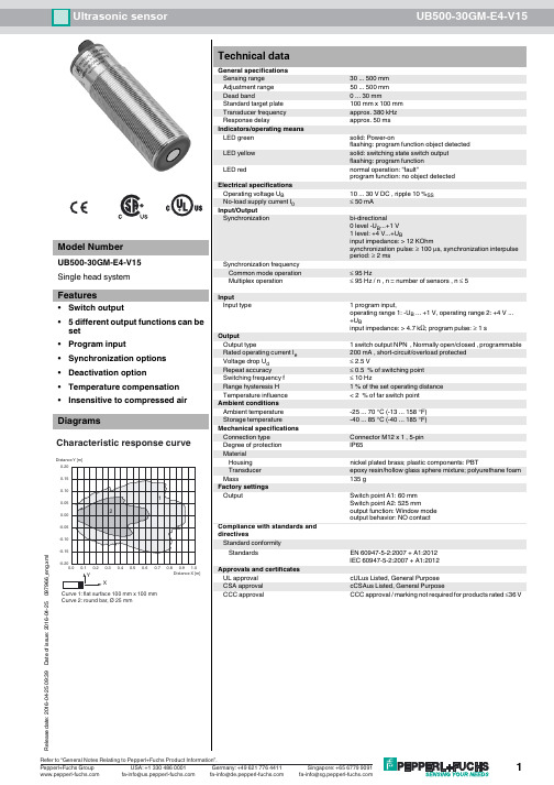
Ultrasonic sensorUB500-30GM-E4-V1516-04-25 09:39D a t e o f i s s u e : 2016-04-25097966_e n g .x m lDimensionsElectrical ConnectionPinout36LEDM30 x 1.552294Standard symbol/Connections:(version E4, npn)Switch outputProgram inputSync. inputWire colors in accordance with EN 60947-5-2.14532+ U B- U B (BN)(BK)(WH)(GY)(BU)U 134521 B N2 WH3 BU4 BK5 GYWire colors in accordance with EN 60947-5-2(brown)(white)(blue)(black)(gray)Additional InformationProgrammable output modes1. Window mode, normally open mode A1 < A2:2. Window mode, normally closed mode A2 < A1:3. One switch point, normally open mode A1 -> ∞:5. A1 -> ∞, A2 -> ∞: Object presence detection mode Object detected: Switch output closed No object detected: Switch output open4. One switch point, normally closed mode A2 -> ∞:object distanceA1A2A2A1A2A116-04-25 09:39D a t e o f i s s u e : 2016-04-25097966_e n g .x m lDescription of Sensor FunctionsProgramming procedureThe sensor features a programmable switch output with two programmable switch points. Programming the switch points and the operating mode is done by applying the supply voltage -U B or +U B to the Teach-In input. The supply voltage must be applied to the Teach-In input for at least 1s. LEDs indicate whether the sensor has recognized the target during the programming procedure.Note:If a programming adapter UB-PROG2 is used for the programming procedure, button A1 is assigned to -U B and button A2 is assigned to +U B .Programming of the switch outputWindow ModesNormally open (NO) output1.Place the target at the near end of the desired switch window2.Program the window boundary by applying -U B to the Teach-In input (yellow and green LEDs flash)3.Disconnect the Teach-In input from -U B to save the window boundary4.Place the target at the far end of the desired switch window5.Program the window boundary by applying +U B to the Teach-In input (yellow and green LEDs flash)6.Disconnect the Teach-In input from +U B to save the window boundary Normally closed (NC) output1.Place the target at the near end of the desired switch window2.Program the window boundary by applying +U B to the Teach-In input (yellow and green LEDs flash)3.Disconnect the Teach-In input from +U B to save the window boundary4.Place the target at the far end of the desired switch window5.Program the window boundary by applying -U B to the Teach-In input (yellow and green LEDs flash)6.Disconnect the Teach-In input from -U B to save the window boundarySwitch Point ModesNormally open (NO) output1.Place the target at the desired switch point position2.Program the switch point by applying +U B to the Teach-In input (yellow and green LEDs flash)3.Disconnect the Teach-In input from +U B to save the switch point4.Cover the sensor face with hand or remove all objects from sensing range5.Program the switch point by applying -U B to the Teach-In input (red and yellow LEDs flash)6.Disconnect the Teach-In input from -U B to save the switch point Normally closed (NC) output1.Place the target at the desired switch point position2.Program the switch point by applying -U B to the Teach-In input (yellow and green LEDs flash)3.Disconnect the Teach-In input from -U B to save the switch point4.Cover the sensor face with hand or remove all objects from sensing range5.Program the switch point by applying +U B to the Teach-In input (red and yellow LEDs flash)6.Disconnect the Teach-In input from +U B to save the switch pointObject Detection Mode1.Cover the sensor face with hand or remove all objects from sensing range2.Apply -U B to the Teach-In input (red and yellow LEDs flash)3.Disconnect the Teach-In input from +U B to save the setting4.Apply +U B to the Teach-In input (red and yellow LEDs flash)5.Disconnect the Teach-In input from +U B to save the settingFactory settings See technical data.DisplayThe sensor provides LEDs to indicate various conditions.Mounting flange, 30 mmBF 30-FMounting flange with dead stop, 30 mmBF 5-30Universal mounting bracket for cylindrical sensors with a diameter of 5...30mm UVW90-M30Ultrasonic -deflector UVW90-K30Ultrasonic -deflector UB-PROG2Programming unitV15-G-2M-PVCFemale cordset, M12, 5-pin, PVC cable16-04-25 09:39D a t e o f i s s u e : 2016-04-25097966_e n g .x m lSynchronizationThis sensor features a synchronization input for suppressing ultrasonic mutual interference ("cross talk"). If this input is not connected, the sensor will operate using internally generated clock pulses. It can be synchronized by applying an external square wave. The pulse duration must be ≥100 µs. Each falling edge of the synchronization pulse triggers transmission of a single ultrasonic pulse. If the synchronization signal remains low for ≥ 1 second, the sensor will revert to normal operating mode. Normal operating mode can also be activated by opening the signal connection to the synchronization input (see note below).If the synchronization input goes to a high level for > 1 second, the sensor will switch to standby mode, indicated by the green LED. In this mode,the outputs will remain in the last valid output state.Note:If the option for synchronization is not used, the synchronization input has to be connected to ground (0 V) or the sensor must be operated via a V1 cordset (4-pin).The synchronization function cannot be activated during programming mode and vice versa.The following synchronization modes are possible:1.Several sensors (max. number see technical data) can be synchronized together by interconnecting their respective synchronization inputs.In this case, each sensor alternately transmits ultrasonic pulses in a self multiplexing mode. No two sensors will transmit pulses at the same time (see note below).2.Multiple sensors can be controlled by the same external synchronization signal. In this mode the sensors are triggered in parallel and are syn-chronized by a common external synchronization pulse.3.A separate synchronization pulse can be sent to each individual sensor. In this mode the sensors operate in external multiplex mode (see note below).4.A high level (+U B ) on the synchronization input switches the sensor to standby mode.Note:Sensor response times will increase proportionally to the number of sensors that are in the synchronization string. This is a result of the multiplex-ing of the ultrasonic transmit and receive signal and the resulting increase in the measurement cycle time.Installation conditionsIf the sensor is installed in an environment where the temperature can fall below 0 °C, one of these mounting flanges must be used for mounting:BF30, BF30-F, or BF 5-30.If the sensor is mounted in a through hole using the included steel nuts, it must be mounted at the middle of the threaded housing. If it must be mounted at the front end of the threaded housing, plastic nuts with centering ring (optional accessories) must be used.Green LEDRed LED Yellow LED During Normal operation Proper operationInterference (e.g. compressed air)On Off Off Flashing Switching state Previous state During sensor programming Object detected No object detectedObject uncertain (programming invalid)Flashing Off OffOff Flashing FlashingFlashing Flashing Flashing。
Pepperl+Fuchs UC6000-30GM-2EP-IO-V15 超音波传感器说明书
Ultrasonic sensorUC6000-30GM-2EP-IO-V15R e l e a s e d a t e : 2017-10-24 12:02D a t e o f i s s u e : 2017-10-27191245_e n g .x m lStandards EN 60947-5-2:2007+A1:2012IEC 60947-5-2:2007 + A1:2012Approvals and certificates UL approval cULus Listed, General Purpose CSA approval cCSAus Listed, General Purpose CCC approval CCC approval / marking not required for products rated ≤36 VDimensionsElectrical ConnectionPinout32ø73365LED6893ø7M12106Switch output 215234L+L-Sync.C/Q134521 BN2 WH3 BU4 BK 5GYWire colors in accordance with EN 60947-5-2(brown)(white)(blue)(black)(gray)Additional InformationSwitching output operating modesNearswitching pointFar switching pointNO contactNC contactNO contactNC contactNO contact NC contact1. Switching point mode2. Window mode3. Hysteresis mode NO contact NC contact4. Retroreflective sensor modeR e l e a s e d a t e : 2017-10-24 12:02D a t e o f i s s u e : 2017-10-27191245_e n g .x m l Description of Sensor FunctionsProgrammingThe sensor is equipped with two outputs. Two switching points or trip values as well as the output mode, can be programmed for each output.The shape of the sensor sound cone can also be programmed. These parameters can be configured using two different methods:-Using the sensor push buttons-Using the IO-link interface of the sensor. This method requires an IO-link master (e.g. IO-link master01 USB) and the associated software.The download link is available on the product page for the sensor with the IO link at www.pepperl-fuchs.deConfiguration using the push buttons is described below. To configure the parameters using the sensor IO-link interface, please read the software description. The processes for configuring the switching points and the sensor operating modes run completely independently and do not influ-ence one another.Note:-The sensor can only be programmed during the first 5 minutes after switching on. This time is extended during the actual programming pro-cess. The option of programming the sensor is revoked if no programming activities take place for 5 minutes. After this, programming is no longer possible until the sensor is switched off and on again.-The programming activities can be canceled at any time without changing the sensor settings. To do so, press and hold the push button for 10 seconds.Programming the switch pointsNote:Each push button is assigned to a physical output. Switching output 1 (C/Q) is programmed via push button T1. Switching output 2 is programmed via push button T2. The status of switching output 1 is indicated by the yellow LED L1. The status of switching output 2 is indicated by the yellow LED L2.Programming the near switch point1.Position the object at the site of the required near switch point.2.Press and hold the push button for 2seconds (yellow LED flashes).3.Briefly press the push button (green LED flashes 3 times as confirmation). The sensor returns to normal mode.Programming the distant switch point1.Position the object at the site of the required distant switch point2.Press and hold the push button for 2seconds (yellow LED flashes)3.Press and hold the push button for 2seconds (green LED flashes 3 times as confirmation). The sensor returns to normal mode.Programming the operating modeThe sensor features a 3-stage process for programming the sensor operating modes. You can program the following with this process:1.Output function2.Output behavior of the switching output3.The beam widthThese 3 stages of the process are programmed in succession. To switch from one programming function to the next, press and hold the push button for 2seconds.Accessing the programming routineThe operating mode can be programmed separately for each of the two switching outputs. The switching output 1 (C/Q) operating mode is pro-grammed via push button T1. The switching output 2 operating mode is programmed via push button T2.To access the programming routine for the sensor operating mode, press the push button for 5seconds.Programming the output function of the switching outputThe green LED is now flashing. The number of flashes indicates the output function currently programmed:1x: Switching point mode 2x: Window mode 3x: Hysteresis mode 4x: Reflective mode1.Briefly press the push button to navigate through the output functions in succession. Use this method to choose the required output function.2.Press and hold the push button for 2seconds to save the selection and switch to the programming routine for the output behavior.Programming the output behavior for the switching outputThe yellow LED is now flashing. The number of flashes indicates the output behavior currently programmed:1x: NO contact 2x: NC contact1.Briefly press the push button to switch between the possible output behaviors in succession. Use this method to choose the output behavior.2.Press and hold the push button for 2seconds to save the selection and switch to the programming routine for the sound cone.IO-Link master, supply via USB port or separate power supply, LED indicators, M12 plug for sensor connection BF 30Mounting flange, 30 mmBF 30-FMounting flange with dead stop, 30 mmBF 5-30Universal mounting bracket for cylindrical sensors with a diameter of 5...30mm V15-W-2M-PVCFemale cordset, M12, 5-pin, PVC cableR e l e a s e d a t e : 2017-10-24 12:02D a t e o f i s s u e : 2017-10-27191245_e n g .x m l Programming the beam widthThe red LED is now flashing. The number of flashes indicates the beam witdht currently programmed:1x: narrow 2x: medium 3x: wide1.Briefly press the push button to navigate through the different beam widths in succession. Use this method to choose the required beam width.2.Press and hold the push button for 2seconds to return to normal operation mode.NoteThe last beam width programmed applies for both outputs in equal measure.Resetting the sensor to the factory settingsThe sensor can be reset to the original factory settings.1.Disconnect the sensor from the power supply 2.Press and hold one of the push buttons3.Connect the power supply (yellow and red LEDs flash simultaneously for 5seconds, followed by the yellow and green LEDs flashing simul-taneously)4.Release the push buttonThe sensor will now function with the original factory settings.Factory settingsSee technical data.IndicatorsThe sensor has four LEDs for indicating the status and two buttons for setting parameters.SynchronizationThe sensor is fitted with a synchronization input that suppresses mutual interference from external ultrasonic signals. If this input is not connected,the sensor operates with internally generated cycle pulses. The sensor can be synchronized by creating external rectangular pulses and by set-ting the appropriate parameters via the IO-link interface. Each falling pulse edge sends an individual ultrasonic pulse. If the signal at the synchro-nization input is low for >1second, the sensor reverts to the normal, unsynchronized operating mode. This also occurs if the synchronization input is disconnected from external signals (see note below).If a high signal is applied to the synchronization input for > 1 second, the sensor switches to standby. This is indicated by the green LED. In this operating mode, the last recorded output statuses are retained. Please observe the software description in the event of external synchronization.Note:If the option of synchronizing is not used, the synchronization input must be connected to ground (L-) or the sensor must be operated with a V1-connection cable (4-pin).The option of synchronization is not available during the programming process. During synchronization, the sensor can switch to programming via the IO-link interface. This interrupts the synchronization process and the sensor is no longer synchronized.The following synchronization modes are available:1.Multiple sensors (see Technical data for the maximum number) can be synchronized by connecting the synchronization inputs on the sen-sors. In this case, the sensors synchronize themselves in succession in multiplex mode. Only one sensor sends signals at any one time.(See note below)2.Multiple sensors (see Technical data for the maximum number) can be synchronized by connecting the synchronization inputs on the sen-sors. The sensor interface can be used to parameterize the sensors so that one functions as a master and the others function as slaves.(See interface description) In this case, the sensors in master/slave mode work simultaneously, i.e. in synchronization where the master sen-sor plays the role of an intelligent external impulse generator.3.Multiple sensors can be controlled collectively by an external signal. In this case, the sensors are triggered in parallel and operate synchro-nously, i.e. at the same time. All sensors must be parameterized via the sensor interface so that they are set to external. See the softwareR e l e a s e d a t e : 2017-10-24 12:02D a t e o f i s s u e : 2017-10-27191245_e n g .x m ldescription.4.Several sensors are controlled with a time delay by an external signal. In this case, only one sensor is externally synchronized at any one time (see note below). All sensors must be parameterized via the sensor interface so that they are set to external. See the software descrip-tion.5.A high signal (L+) or a low signal (L-) at the synchronization input switches the sensor to standby in the case of external parameterization.Note:The response time of the sensors increases in proportion to the number of sensors in the synchronization chain. In multiplex mode, the measuring cycles of the individual sensors run in succession in a chronological sequence.Note:The synchronization connection of the sensors supplies an output current in the case of a low signal, and generates an input impedance in the case of a high signal. Please note that the synchronizing device must have the following driver properties:Driver current according to L+ > n * high level signal/input impedance (n = number of sensors to be synchronized)Driver current according to L- > n * output current (n = number of sensors to be synchronized).。
倍加福UC2000-30GM-IUR2-V15 检测传感器
ULTRA3000
软件
UC-30GM-R2
附件
DA5-IU-2K-V
显示表
V15-G-2M-PVC
电缆连接器
V15-W-2M-PVC
电缆连接器
Release date: releasedate Issue date: 2007-10-09 104093_CN.xml
ḋᴀݙᆍᬍᯊᘩϡ䗮ⶹ
Copyright Pepperl+Fuchs, Printed in Germany
10 ... 30 V DC, 纹波 10 %PP ≤ 900 mW
RS 232, 9600 Bit/s, 无奇偶校验 , 8 数据位 , 1 停止位
双向 0-level: -UB ... +1 V 1-level: +4 V ... +UB 输入阻抗 : > 12 kOhm 同步脉冲 : ≥ 100 μs, 同步脉冲周期 : ≥ 2 ms
脉冲。 2. 在多个传感器的同步输入端加载同一个脉冲信号可使传感器同步工作。 3. 将同步脉冲循环的发送给每个传感器的同步端使传感器在多重模式下工作。 4. 在同步输入端加载高电平,传感器停止工作。
因为同步功能增加了测量周期时间,所以当传感器同步工作时,响应时间将增加。
注: 如果不需要使用同步功能,同步输入端必须接地(0 V)或者使用 V1 连接器(4 针)。
LED-ش੨
用接口电缆 UC-30GM-R2 通讯的说明
通过 UC-30GM-R2 接口电缆使用 ULTRA 3000 应用软件可实现与超声波传感器的通讯。电缆连接了 PC 232 串口和传感器的温 度 / 设定插头。当建立与传感器的连接时,请确认插头排列正确,否则通讯不能建立。圆形插头的突出部分必须被插入到传感 器侧插座的凹槽处而不是箭头标志处。
Pepperl+Fuchs UC2000-L2-E6-V15 超声传感器说明书
Ultrasonic sensor UC2000-L2-E6-V15R e l e a s e d a t e : 2016-02-15 13:04D a t e o f i s s u e : 2016-02-15277765_e n g .x m lDimensionsElectrical ConnectionPinoutLED yeLED gn LED ye LED gn 37M 12 x 12867402030405.5ø 5.54660T 1T 2o u t 1p w r /o u t 240Synchronization Switch output 1Switch output 215234L+L-134521 B N2 WH3 BU4 BK5 GYWire colors in accordance with EN 60947-5-2(brown)(white)(blue)(black)(gray)R e l e a s e d a t e : 2016-02-15 13:04D a t e o f i s s u e : 2016-02-15277765_e n g .x m lDescription of Sensor FunctionsProgramming procedureThe sensor features two outputs with two programmable switch points, each (for a total of 4). Programming the switch points and the operating mode can be done in two different ways:-via the sensor’s programming buttons-via the serial interface, which requires an external interface adapterThe procedure for programming via the sensor's programming buttons is described below. For programming using the serial interface, please refer to the software manual.Switch points and operating modes of each output can be programmed independently without influencing each other.Note:-Programming is enabled for 5 minutes after power-on. After 5 minutes without programming activity the programming feature will be locked.-During any programming step it is possible to leave the programming routine without changing the sensor settings by pressing the currently used programming button for 10 s.Programming the Switch PointsNotes:-The description below leads you through programming output 1’s switch points. The procedure for output 2 is exactly the same with the only difference, being to use the Programming Button T2.-If the red LED flashes during the programming procedure, it indicates uncertain target detection. In this case, please correct the target alignment until the yellow LED flashes. The new settings will only be stored in the sensor’s memory if the yellow LED flashes.Programming the Near Switch Point1.Place the target at the desired near switch point position2.Press Programming Button T1 for 2s (corresponding yellow LED flashes)3.Press Programming Button T1 briefly (green LED flashes three times for confirmation). The sensor returns to normal operation.Programming of the Far Switch Point1.Place the target at the desired far switch point position2.Press Programming Button T1 for 2s (corresponding yellow LED flashes)3.Press Programming Button T1 for 2s (green LED flashes three times for confirmation). The sensor returns to normal operation.Programming Modes of OperationNote:The description below leads you through programming of the modes of operation for output 1. The procedure for output 2 is exactly the same with the only difference,being to use Programming Button T2.The sensor provides a three step routine to program the modes of operation. In this routine you can program:1.Output function 2.Output behavior 3.Beam widthProgramming the modes is carried out sequentially. To toggle from one mode to the next, press the Programming button for 2s.Press Programming Button T1 for 5s to enter the operating modes programming routine.Programming the output function1.The green LED flashes. The number of flashes indicates the current output function:single flash: Switch point output function double flash: Window output function triple flash: Hysteresis output function.2.Press Programming Button T1 briefly to toggle sequentially through these output functions and select the desired mode.3.Press Programming Button T1 for 2s to save and enter the programming routine for output behavior Programming the output behavior1.The yellow LED flashes. The number of flashes indicates the current output behavior:single flash: Normally Open (NO)double flash: Normally Closed (NC).2.Press Programming Button T1 briefly to toggle sequentially through these output behaviors and select the desired mode.3.Press Programming Button T1 for 2s to save and enter the programming routine for beam width.Programming the beam width1.The red LED flashes. The number of flashes indicates the current beam width setting:single flash: narrow double flash: medium triple flash: wide.Programming adapter PACTware 4.X FDT FrameworkUltraschall-Sensoren DTMDTM devices for communication with cube style and UMC... sensors V15-G-2M-PVCFemale cordset, M12, 5-pin, PVC cable Microsoft .NETR e l e a s e d a t e : 2016-02-15 13:04D a t e o f i s s u e : 2016-02-15277765_e n g .x m l2.Press Programming Button T1 briefly to toggle sequentially through these beam shapes.3.Press Programming Button T1 for 2s to save and exit the operating modes programming routine.Note:Independently programming the beam width for each individual output is not possible. The last programmed beam width is valid for both outputs. It doesn’t matter which Pro-gramming Button is used.Reset Sensor to Factory SettingsThe sensor has a feature to reset to factory settings 1.Disconnect the sensor from power supply2.Press and hold one of the Programming Buttons T1 or T23.Connect Sensor to power supply (red and yellow LED flash simultaneously for 5s then green and yellow LED flash simultaneously)4.Release Programming ButtonThe sensor now operates with default factory settings.Factory settingsSee technical data.DisplayThe sensor is provided with LEDs to indicate various conditions.*) off if yellow LED out2 is onSynchronizationThis sensor features a synchronization input for suppressing ultrasonic mutual interference ("cross talk"). If this input is not connected, the sensor will operate freewheeling using internally generated clock pulses. It can be synchronized by applying an external square wave or by means of appropriate programming via the serial interface. Each falling edge of the synchronization pulse triggers transmission of a single ultrasonic pulse. If the synchronization signal remains low for ≥ 1 second, the sensor will revert to normal operating mode. Normal operating mode can also be activated by opening the signal connection to the synchronization input.(See note below)If the synchronization input goes to a high level for > 1 second, the sensor will switch to standby mode, indicated by the green LED. In this mode, the output(s) will remain in the last valid output state. When using the external synchronization feature, please refer to the software description.Note:If the option for synchronization is not used, the synchronization input has to be connected to ground (0V) or the sensor has to be operated via a V1 cordset (4-pin).The synchronization function cannot be activated during programming mode and vice versa.The following synchronization modes are possible:1.Several sensors (max. number see technical data) can be synchronized together by interconnecting their respective synchronization inputs. In this case, each sensor alternately transmits ultrasonic pulses in a self multiplexing mode. No two sensors will transmit pulses at the same time. (See note below)2.Several sensors (max. number see technical data) can be synchronized together by interconnecting their respective synchronization inputs. Due to programming via the sensors interface one sensor acts as a master device, all the others as slave devices. (see description of the interface) In this master / slave mode the sensors are triggered in parallel and are synchronized by a common synchronization pulse, provided by the master device.3.Multiple sensors can be controlled by the same external synchronization signal. In this mode the sensors are triggered in parallel and are synchronized by a common external synchronization pulse. All sensors must be parameterized for external synchronization by means of the sensor interface. See software description.4. A separate synchronization pulse can be sent to each individual sensor. In this mode the sensors operate in external multiplex mode. (See note below). All sensors must be parameterized for external synchronization by means of the sensor interface. See software description.5. A high level (+U B ) or a low level (-U B )on the synchronization input switches the sensor to standby mode if it is parameterized for external synchronization.Note:Sensor response times will increase proportionally to the number of sensors that are in the synchronization string. This is a result of the multiplexing of the ultrasonic transmit and receive signal and the resulting increase in the measurement cycle time.Note:The sensors syncronization input delivers an output current in case of low level and burdens with its input impedance in case of high level. Please pay attention that the syn-chronizing device needs to have that driver capability:driver current against +U B ≥ n * high-level/input impedance (n = number of sensors to be synchronized)driver current against 0V ≥ n * output current (n = number of sensors to be synchronized).Green LEDYellow LED out1 / out2Red LED During Normal operation Proper operationInterference (e.g. compressed air)On *)Off Switching state output 1 / output 2remains in previous stateOff On During Switch Point Programming Object detected No object detectedConfirmation after Programming Programming failed warningOff OffTriple flashingOff Flashing Off Off Off Off Flashing OffTriple flashing During Sensor Mode Programming Programming the output function Programming the output behaviour Programming the beam widthFlashing Off OffOff Flashing OffOff Off Flashing。
倍加福超声波传感器资料
-25 ... 70OC (248 ... 343K) -40 ... 85OC (233 ... 358K)
IP65 连接器V15 (M12 x 1), 5 针
黄铜镀镍 环氧树脂 / 空心玻璃球混合物,聚氨基甲酸泡沫塑料 外罩 PBT 140 g
样本内容更改时恕不通知
德国P+F公司 1722
电气连接
标准符合 / 连接 (version I)
1 (棕) 2 (白) 5 (灰) 4 (黑)
3 (蓝)
不用 同步输入 模拟量输出
线芯颜色符合 EN 60947-5-2
标准符合 / 连接 (version U)
1 (棕) 2 (白) 5 (灰) 4 (黑)
3 (蓝)
不用 同步输入 模拟量输出
线芯颜色符合 EN 60947-5-2
内部同步 内部同步时传感器同步输入端依次连接。供电后,传感器工作于多重模式 。响应时间增加取决于同步的传感器数目。示教时不能同步,反之亦然。 示教开关点时传感器必须处于非同步状态。
示教开关点
LED 位置
绿 红 黄
开关点 1 将目标置入 期望的位置 按压A1键大于2秒
当目标被检测 到时确认
开关点 2 将目标置入 期望的位置 按压A2键大于2秒
电话:上海(021)66303939(总机) 传真:(ቤተ መጻሕፍቲ ባይዱ21)66300883 网址:www.pepperl-fuchs.com
超声波传感器
21.超声波传感器 超声波传感器
倍加福
UB2000-F42-I-V15 / UB2000-FK4C2-MU--5V11*5
同步 为抑制超声波传感器相互之间干扰,该传感器具有同步输入端。如果这个同 步输入端不用,则传感器内部靠内部触发的脉冲工作。多只传感器同步工同 靠以下方式实现。
倍加福UC200030GME5V15传感器说明书
ਸ࠲ݛ๕
1. ش੨ఇ๕Ljਸ A1 < A2: Ⳃᷛ⠽㣗ೈ
A1
2. ش੨ఇ๕LjԿ A2 < A1:
A2
A2
3. ڇਸ࠲ۅఇ๕Ljਸ A1 -> ∞:
A1
A2
4. ڇਸ࠲ۅఇ๕LjԿ A2 -> ∞:
A1
5. A1 -> ∞, A2 -> ∞: ణՔ٪ሞॠ֪ ॠ֪ڟణՔǖਸ࠲Կࢇ !!࿄ॠ֪ڟణՔǖਸ࠲ٶਸ
输出 输出类型 重复精度 额定工作电流 Ie 电压降 Ud
22
94
超声波接近开关
接近开关功能说明 同步 接近开关有一个同步输入端可以抑制接近开关之间的相互影响。如果同步输入端不 接,接近开关则根据内部产生的时钟频率工作。多个接近开关的同步功能也可以依 照下列方式实现: 外部同步 : 在接近开关的同步输入端上加载一个脉冲宽度大于 100 s 的方波脉冲, 可以实现同 步工作。同步输入端上的同步脉冲启动一个测量周期,测量周期由同步脉冲的下降 沿触发。外部同步有两个模式可选: 1. 在多个接近开关的同步输入端加载同一个脉冲信号可使接近开关同步工作。 2. 将同步脉冲循环发送给每个接近开关的同步端可使接近开关在多重模式下工作。 内部同步 : 内部同步功能最多可连接 5 个接近开关。 通电后, 这些接近开关工作在多重模式下。 开关输出的状态不会改变,直到开关的阀值超过内部五次测量平价值的五倍。如果 低电平持续时间超过 1 s 或者同步输入端开路,接近开关则会进入正常工作状态。 设定时不能同步工作,同步工作时也不能设定开关点。接近开关必须工作在非同步 状态下才能设定开关点。在同步输入端加载一个高电平可使接近开关停止工作。 注: 如果不需要使用同步功能,同步输入端必须接地(0 V)或者使用 V1 电缆连接器(4 针) 。 设置开关点 超声波接近开关有一个开关量输出,对应的两个开关点可设置。设置方法是将 TEACH-IN输入端分别连接电源-UB或者+UB来实现, 连接时间至少为1秒钟。 在设置 过程中,LED 灯指示接近开关是否检测到了目标物。TEACH-IN 输入端连接 -UB 时 设置 A1 点,连接 +UB 时设置 A2 点。使用编程附件 UB-PROG2 可令设置开关点和 输出功能的过程变得简单。 可选下列五种不同的输出功能 : 1. 窗口模式,常开 2. 窗口模式,常闭 3. 开关点模式,常开 4. 开关点模式,常闭 5. 物体存在检测模式 窗口模式,常开 - 将目标物放在近开关点 - 把 TEACH-IN 输入端连接 -UB 设置 A1 点 - 将目标物放在远开关点 - 把 TEACH-IN 输入端连接 +UB 设置 A2 点 窗口模式,常闭 - 将目标物放在近开关点 - 把 TEACH-IN 输入端连接 +UB 设置 A2 点 - 将目标物放在远开关点 - 把 TEACH-IN 输入端连接 -UB 设置 A1 点 开关点模式,常开 - 将目标物放在近开关点 - 把 TEACH-IN 输入端连接 +UB 设置 A2 点 - 用手遮住接近开关或者移开接近开关检测范围内的所有物体 - 把 TEACH-IN 输入端连接 -UB 设置 A1 点 开关点模式,常闭 - 将目标物放在近开关点 - 把 TEACH-IN 输入端连接 -UB 设置 A1 点 - 用手遮住接近开关或者移开接近开关检测范围内的所有物体 - 把 TEACH-IN 输入端连接 +UB 设置 A2 点 物体存在检测模式 - 用手遮住接近开关或者移开接近开关检测范围内的所有物体 - 把 TEACH-IN 输入端连接 -UB 设置 A1 点 - 把 TEACH-IN 输入端连接 +UB 设置 A2 点 出厂设置 A1: A2: 盲区 最大量程
倍加福 P+F 超声波传感器UC2000-30GM-IUR2-V15
外型尺寸-30G M s e r i e s超声波UC500-30GM-IUR2-V15Notes注意D a t e o f i s s u e 07/19/2002型号此超声波传感器有4个温度/设定插头,可连接到4个不同位置。
功能见下表插头位置 含义A1 设定开关点A2 设定开关点E2/E3 切换: 2个独立开关点/窗口功能T 温度补偿设定功能说明:开关点1或2的设定-断开电源-拨下设定插头-恢复电源(复位)-将目标放在需要的开关点上-在位置1和2插上和拨去设定插头。
开关点A1或A2就设好了。
注意;移去温度/设定插头,目标位置值就被采用了。
-设定过程由LED指示。
绿色LED闪烁,目标被检测到;目标没有检测到,红色LED闪烁 -连接设定插头到位置T。
设定过程完成,传感器在正常方式下工作。
开关功能的设定-断电-拨下设定插头-恢复电源(复位)-连接设定插头到E2/E3。
可设定三种不同的工作方式:-开关点方式,LEDA1闪烁-窗口方式,LEDA2闪烁-滞后方式,LEDA1和A2闪烁连接设定插头到位置下。
设定过程完成,传感器在正常方式下工作。
注意:若温度插头在5分钟内没有插入,传感器将回到正常模式(带最新的存储值),不带温度补偿同步此传感器有一个同步输入,用于抑制相互间的干扰。
若不使用这个同步输入端,窜肝气将通过内部激发的时钟频率来工作。
使用方波电压可能同步。
下降沿使超声波脉冲传输。
≥1s的低电平或同步输入端开路使传感器在正常方式下工作。
高电平>1s使传感器在备用方式下工作(绿色LED指示)。
最新状态下输出中断。
同步不可在设定过程中实施,反之亦然。
多路工作方式可行1.把同步输入端相连,可使2到5个传感器同步。
传感器传输超声波脉冲2.多个传感器可以由同一个同步信号来控制。
传感器被置于同步方式3.同步脉冲循环发送到单个传感器。
传感器以同步方式工作。
4.同步输入端的高电平使传感器失能传感器同步时,响应时间增加,因为同步使得检测循环时间加长-初始设置值A1: 近点A2: 标称距离LED显示UC500-30GM-IUR2-V15D a t e o f i s s u e 07/19/2002超声波传感器用软件 ULTRA 2001设定参数----------------连接PC)开关1和2上升输出/下降输出/零线工作方式音速温度漂移(对固有的传感器温升可考虑温度补偿)育区扩展(用于抑制育区回声)检测范围减小(用于远方回声的抑制)检测循环时间声音功率(破裂干扰)灵敏度回声丢失时传感器的动作出错时传感器的动作允许的检测周期数的平均值参数设定选择,RS232或人工设定。
倍加福超声波说明书

外型尺寸-30G M s e r i e s超声波UC4000-30GM-IUR2-V15Notes注意D a t e o f i s s u e 07/19/2002型号此超声波传感器有4个温度/设定插头,可连接到4个不同位置。
功能见下表UC4000-30GM-E7R2-V15设定功能说明:开关点1或2的设定-断开电源-拨下设定插头-恢复电源(复位)-将目标放在需要的开关点上-在位置1和2插上和拨去设定插头。
开关点1或A2就设好了。
注意;移去温度/设定插头,目标位置值就被采用了。
-设定过程由LED指示。
绿色LED闪烁,目标被检测到;目标没有检测到,红色LED闪烁 -连接设定插头到位置T。
设定过程完成,传感器在正常方式下工作。
开关功能的设定-断电-拨下设定插头-恢复电源(复位)-连接设定插头到E2/E3。
可设定三种不同的工作方式:-开关点方式,LEDA1闪烁-窗口方式,LEDA2闪烁-滞后方式,LEDA1和A2闪烁连接设定插头到位置下。
设定过程完成,传感器在正常方式下工作。
注意:若温度插头在5分钟内没有插入,传感器将回到正常模式(带最新的存储值),不带温度补偿同步此传感器有一个同步输入,用于抑制相互间的干扰。
若不使用这个同步输入端,传感器将通过内部激发的时钟频率来工作。
使用方波电压可能同步。
下降沿使超声波脉冲传输。
≥1s的低电平或同步输入端开路使传感器在正常方式下工作。
高电平>1s使传感器在备用方式下工作(绿色LED指示)。
最新状态下输出中断。
同步不可在设定过程中实施,反之亦然。
多路工作方式可行1.把同步输入端相连,可使2到5个传感器同步。
传感器传输超声波脉冲2.多个传感器可以由同一个同步信号来控制。
传感器被置于同步方式3.同步脉冲循环发送到单个传感器。
传感器以同步方式工作。
4.同步输入端的高电平使传感器失能。
传感器同步时,响应时间增加,因为同步使得检测循环时间加长-初始设置值A1: 近点A2: 标称距离LED显示D a t e o f i s s u e 07/19/2002超声波传感器用软件 ULTRA 2001设定参数--------------连接PC)开关1和2上升/下降输出/零线工作方式音速温度漂移(对固有的传感器温升可考虑温度补偿)育区扩展(用于抑制育区回声)检测范围减小(用于远方回声的抑制)检测循环时间声音功率(破裂干扰)灵敏度回声丢失时传感器的动作出错时传感器的动作允许的检测周期数的平均值参数设定选择,RS232或人工设定。
超声波探头UC500-30GM-IUR2-V15
֪ଉ!ۅ 2
LED-ش੨
用接口电缆 UC-30GM-R2 通讯的说明 通过 UC-30GM-R2 接口电缆使用 ULTRA 3000 应用软件可实现与超声波接近开关的通讯。 电缆连接了 PC 232 串口和接近开关 的温度 / 设定插头。当建立与接近开关的连接时,请确认插头排列正确,否则通讯不能建立。圆形插头的突出部分必须被插入 到接近开关侧插座的凹槽处而不是箭头标志处。 用应用软件 ULTRA 3000 设定参数 - 开关点 A1 和 A2 - 上升 / 下降 / 零线模式 - 工作模式 - 声速 - 温度漂移 (对固有的接近开关温升可考虑在温度补偿内) - 盲区扩展 (用于抑制盲区回声) - 检测范围的缩小 (用于远程回声的抑制) - 测量周期的时间 - 声功率 (脉冲串周期的干扰) - 灵敏度 - 回波丢失时接近开关的动作 - 出错时接近开关的动作 - 允许测量周期数的平均值 - 参数设定选择, RS232 或人工设定
LED !!!!ࣜ ມ-LED ୴/ࢤ LED !!!!ࣜ
RS 232-থ੨
ӈ֣ ࿒܈/Պ֭ײཀྵ (ᆯথ੨ۉમ UC-30GM-R2 থPC) 1: TXD 2: RXD 3: փᆩ 4: ں
V15-֭ཀྵ (M12x1)
4 3 1 2
E2 A1 "ཚ"ۉ/߅ඡ A2
E3
֪ଉ!ۅ 1
ḋᴀݙᆍᬍᯊᘩϡ䗮ⶹ
UC-30GM-TEMP
附件
UC-30GM-PROG
附件
ULTRA3000
软件
UC-30GM-R2
附件
DA5-IU-2K-V
显示表
V15-G-2M-PVC
电缆连接器
盲区 最大量程 上升模式
倍加福超声波说明书

外型尺寸-30G M s e r i e s超声波UC4000-30GM-IUR2-V15Notes注意D a t e o f i s s u e 07/19/2002型号此超声波传感器有4个温度/设定插头,可连接到4个不同位置。
功能见下表UC4000-30GM-E7R2-V15设定功能说明:开关点1或2的设定-断开电源-拨下设定插头-恢复电源(复位)-将目标放在需要的开关点上-在位置1和2插上和拨去设定插头。
开关点1或A2就设好了。
注意;移去温度/设定插头,目标位置值就被采用了。
-设定过程由LED指示。
绿色LED闪烁,目标被检测到;目标没有检测到,红色LED闪烁 -连接设定插头到位置T。
设定过程完成,传感器在正常方式下工作。
开关功能的设定-断电-拨下设定插头-恢复电源(复位)-连接设定插头到E2/E3。
可设定三种不同的工作方式:-开关点方式,LEDA1闪烁-窗口方式,LEDA2闪烁-滞后方式,LEDA1和A2闪烁连接设定插头到位置下。
设定过程完成,传感器在正常方式下工作。
注意:若温度插头在5分钟内没有插入,传感器将回到正常模式(带最新的存储值),不带温度补偿同步此传感器有一个同步输入,用于抑制相互间的干扰。
若不使用这个同步输入端,传感器将通过内部激发的时钟频率来工作。
使用方波电压可能同步。
下降沿使超声波脉冲传输。
≥1s的低电平或同步输入端开路使传感器在正常方式下工作。
高电平>1s使传感器在备用方式下工作(绿色LED指示)。
最新状态下输出中断。
同步不可在设定过程中实施,反之亦然。
多路工作方式可行1.把同步输入端相连,可使2到5个传感器同步。
传感器传输超声波脉冲2.多个传感器可以由同一个同步信号来控制。
传感器被置于同步方式3.同步脉冲循环发送到单个传感器。
传感器以同步方式工作。
4.同步输入端的高电平使传感器失能。
传感器同步时,响应时间增加,因为同步使得检测循环时间加长-初始设置值A1: 近点A2: 标称距离LED显示D a t e o f i s s u e 07/19/2002超声波传感器用软件 ULTRA 2001设定参数--------------连接PC)开关1和2上升/下降输出/零线工作方式音速温度漂移(对固有的传感器温升可考虑温度补偿)育区扩展(用于抑制育区回声)检测范围减小(用于远方回声的抑制)检测循环时间声音功率(破裂干扰)灵敏度回声丢失时传感器的动作出错时传感器的动作允许的检测周期数的平均值参数设定选择,RS232或人工设定。
UC6000雷达料位计中文说明书

3
ḋᴀݙᆍᬍᯊᘩϡ䗮ⶹ
Copyright Pepperl+Fuchs, Printed in Germany
超声波接近开关
外形尺寸
ø73
UC6000-30GM-IUR2-V15
19 5 32.5
36
UC6000-30GM-IUR2-V15
特性
• 通过可编程接口使用 ULTRA 3000 软件进 行接近开关参数设定 • 电流和电压输出 • 同步功能 • 声功率和灵敏度可调 • 温度补偿
⏽ᑺ㸹ٓ 㓪ᦦ༈ M30x1.5
2
0.0
-0.5
-1.0
-1.5 0.0
1.0
2.0
3.0
4.0
5.0
6.0
7.0
Y X ൸၍1ǖೝӱ 100 mm x 100 mm ൸၍2ǖᇶԀ Ø 25 mm
8.0 9.0 ਐ X [m]
设定检测范围的边界点 1 或 2 - 切断电源 - 拔下设定插头 - 再次通电 (重启) - 把目标物放置在所需的边界点上 - 把插头插入对应的 A1 或 A2 位置再拔出,边界点 A1 和 A2 就设定完成了。 注意:拔出温度 / 设定插头的同时,目标物位置值将被保存 - 设定过程可由 LED 灯指示。绿灯闪烁时,目标物被检测到;红灯闪烁时,目标物 未被检测到。 - 将设定插头插入 T 位置,设定过程结束,设定值被保存。 - 接近开关进入正常工作模式 设定输出功能 - 切断电源 - 拔出设定插头 - 再次通电 (重启) - 将设定插头插入 E2/E3 位置,通过多次拔插,可循环地设置三种不同的输出模式 : 1) 上升模式, LED A2 灯闪烁 2) 下降模式, LED A1 灯闪烁 3) 零线模式, LED A1 和 A2 灯同时闪烁 - 将设定插头插入 T 位置,设定过程结束,保存所设定的工作模式。 - 接近开关进入正常工作模式 说明: 如果温度 / 设定插头在五分钟内未插入 T 位置,接近开关将进入正常工作模 式 (带最新储存的参数值) ,但将失去温度补偿功能。 同步输入端 接近开关有一个同步输入端可以抑制接近开关之间的相互影响。如果同步输入端不 接,接近开关则根据内部产生的时钟频率工作。 在接近开关的同步输入端上加载一 个脉冲宽度大于 100 s 的方波脉冲,可以实现同步工作。同步输入端上的同步脉冲 启动一个测量周期,测量周期由同步脉冲的下降沿触发。 持续时间大于 1 s 的低电平或者同步输入端开路,接近开关则根据自身内部频率工 作。 如果在同步输入端加上大于 1 s 的高电平,接近开关进入待机模式(绿色指示灯) 。 输出停止在最后的状态。
Pepperl+Fuchs UB2000-F42-U-V15 1U 超声传感器说明书

Ultrasonic sensorUB2000-F42-U-V1516-02-26 11:32D a t e o f i s s u e : 2019-01-25133991_e n g .x m lDimensionsElectrical ConnectionPinoutMembrane keysLED window7.552.515.55.253415M 12x 180658065163422A 1A 2T E A C H I NM O D ES E TStandard symbol/Connections:(version U)T eaching inputSync.Analog outputCore colours in accordance with EN 60947-5-2.12435+ U B- U B (BN)(WH)(GY)(BK)(BU)U 134521 BN2 WH3 BU4 BK 5GYWire colors in accordance with EN 60947-5-2(brown)(white)(blue)(black)(gray)Additional InformationA1A1 = 0A2A2A1A2Analogue output programmationObject distanceRising rampFalling rampUnusable areaZero line16-02-26 11:32D a t e o f i s s u e : 2019-01-25133991_e n g .x m lFunctional DescriptionThe sensor may be completely parameterised via two keys on the side panel of the housing. As a special feature provided by this sensor, the ultrasound beam width may be adapted to the environmental conditions at the place of operation of the sensor.Specifying the evaluation limits:The evaluation limits determine the characteristic line and the working range of the analog output. The A2 evaluation limit is specified via the A2 key, analogous to the description above.Alternatively, the evaluation limits may also be specified electrically via the learn input. To specify the A1 evaluation limit, the learn input must be connected to-U B ; to specify the A2 evaluation limit, it must be connected to +U B . Specified values are saved upon the disconnection from the learn input.Evaluation limits may only be specified within the first 5 minutes after Power on. To modify the evaluation limits later, the user may specify the desired values only after a new Power On.Proceed as follows to parameterise the output function and the ultrasound beam width:Press the A1 key during Power on and hold down the key for another second to ensure that the sensor starts the two-step pa-rameterisation of the operating modes.Step 1, parameterisation of the output functionThe output function parameterised last is displayed. All output functions available may be selected via consecutive, brief strokes of the A2 key. These strokes are visualised via short flashes of the green LED.A2 evaluation limit determines the steepness of the output characteristic line.Hold down the A1 key for 2 seconds to save the selected output mode, complete the parameterisation and ensure that the sen-sor returns to normal mode. If you briefly press the A1 key, Step 2 is entered (parameterisation of the ultrasound beam width).Step 2, parameterisation of the ultrasound beam widthVia Step 2, the ultrasound beam width may be adapted to the requirements of the corresponding application.The beam width parameterised last is displayed first. Available beam width settings may be selected via consecutive, brief strokes of the A2 key. These strokes are visualised via the flash sequence of the red LED.Mounting aid for FP and F42 sensors MHW 11Mounting brackets for sensorsDA5-IU-2K-VProcess control and indication equipment V15-G-2M-PVCFemale cordset, M12, 5-pin, PVC cable Specifying the A1 evaluation limit by pressing the A1 keyHolding down the A1key > 2 secondsThe sensor switches to learn mode and the user may specify the A1 evaluation limitPosition the target object at the desired distance The yellow LED of the sensor flashes fast to indicate that the target object is recognised. The red LED flash-es if the object is not recognised.Briefly pressing the A1 keyThe sensor terminates the specification of the A1 eval-uation limit and saves it as a non-volatile value. The specified value is invalid if the object is uncertain (i.e. the red LED lights up at irregular intervals). The learn mode is exited.16-02-26 11:32D a t e o f i s s u e : 2019-01-25133991_e n g .x m lsor returns to normal mode. Briefly press the A1 key to return to Step 1 (parameterisation of the output function).If the parameterisation mode is not terminated within 5 minutes (hold down the A1 key for 2 seconds), the sensor aborts this mode without modifying the settings.SynchronisationThe sensor provides a synchronisation port to suppress mutual influencing. If this port has not been connected, the sensor works at an internally generated cycle rate. Several sensors may be synchronised via the following options.External synchronisation:The sensor may be synchronised via the external application of a square wave voltage. A synchronisation pulse on the syn-chronisation input initiates a measuring cycle. The pulse width must be greater than 100 µs. The measuring cycle is started with the falling edge. A low level > 1 s or an open synchronisation input initiate the transition to normal sensor mode. A high level on the synchronisation input deactivates the sensor.Two modes are possible:- Several sensors are controlled via the same synchronisation signal. The sensors work in common mode.- The synchronisation pulses are forwarded at cyclic intervals to respectively one single sensor. The sensors work in multiplex mode.Self-synchronisation:The synchronisation ports of up to 5 sensors suitable for self-synchronisation are connected to each other. These sensors work in multiplex mode after Power on. The On delay increases depending on the number of sensors to be synchronised. While the learn mode is active, no synchronisation is possible (and vice-versa). To specify the switching points, the sensors must be op-erated in non-synchronised mode. Note:If the synchronisation option is not used, the synchronisation input must be connected to ground (0V) or the sensor must be operated with a (4-pole) V1 connecting cable.。
- 1、下载文档前请自行甄别文档内容的完整性,平台不提供额外的编辑、内容补充、找答案等附加服务。
- 2、"仅部分预览"的文档,不可在线预览部分如存在完整性等问题,可反馈申请退款(可完整预览的文档不适用该条件!)。
- 3、如文档侵犯您的权益,请联系客服反馈,我们会尽快为您处理(人工客服工作时间:9:00-18:30)。
ḋᴀݙᆍᬍᯊᘩϡ䗮ⶹ
Copyright Pepperl+Fuchs, Printed in Germany
2
超声波传感器
LED 显示 运行状态
开关点 A1 设置 检测到目标 未检测到目标 开关点 A2 设置 检测到目标 未检测到目标 输出模式设置 (E2/E3) 开关点模式 窗口模式 迟滞模式 正常工作模式 温度补偿 设定插头拔出或短接 干扰 (如:压缩空气) 待机模式 LED 灯亮指示开关输出闭合
UC2000-30GM-E6R2-V15
双 LED 红 色 黄色 LED A1
绿
LED
黄色 LED A2
闪
暗
闪
暗
暗
闪
闪
暗
闪
暗
暗
闪
暗
闪
暗
闪
亮
暗
闪
暗
亮
暗
暗
闪
亮
暗
闪
闪
亮
暗
开关状态 A1
开关状态 A2
暗
亮
开关状态 A1
开关状态 A2
暗
闪
上次或规定状态 上次或规定状态
闪
暗
先前状态
先前状态
LED-ش੨
LED !!!!ࣜ
A 1 (N.O.) ਸ࠲ 1
A 2 (N.O.) ਸ࠲ 2
ਸ࠲ ۅ1
ړA1 > A2 ้LjघऄྺԿ
ਸ࠲ ۅ2
A 1 (N.C.) ਸ࠲ 1
A2 (N.C.) ਸ࠲ 2 2. ش੨ఇ๕ A1,A2ᅜࢻ࣑
A 1 (N.O.) ਸ࠲ 1
如果在同步输入端加上大于 1 s 的高电平,传感器进入待机模式(绿色指示灯)。输 出停止在最后的状态。
设定时不能同步工作,同步工作时也不能设定开关点。
同步输入端的应用 1. 2 到 5 个传感器的同步输入端连接在一起实现同步,此时传感器轮流发出超声波
脉冲。 2. 在多个传感器的同步输入端加载同一个脉冲信号可使传感器同步工作。 3. 将同步脉冲循环的发送给每个传感器的同步端使传感器在多重模式下工作。 4. 在同步输入端加载高电平,传感器停止工作。
+ UB ཞօ ਸ࠲ଉ!1 ਸ࠲ଉ!2
- UB
温度 / 设定插头 电气参数 工作电压 空载电流 I0 接口 接口类型 输入 / 输出 同步
同步频率 一般操作模式 多重操作模式 输出 输出类型 重复精度 额定工作电流 Ie 电压降 Ud 开关频率 f 迟滞范围 H 温度漂移
V15 থഗ
用应用软件 ULTRA 3000 设定参数 - 开关点 1 和 2 - NO/NC 功能 - 工作模式 - 声速 - 温度漂移 (对固有的传感器温升可考虑在温度补偿内) - 盲区扩展 (用于抑制盲区回声) - 检测范围的缩小 (用于远程回声的抑制) - 测量周期的时间 - 声功率 (脉冲串周期的干扰) - 灵敏度 - 回波丢失时传感器的动作 - 出错时传感器的动作 - 允许测量周期数的平均值 - 响应 / 关断延时 - 开关迟滞 - 参数设定选择, RS232 或人工设定
因为同步功能增加了测量周期时间,所以当传感器同步工作时,响应时间将增加。
-0.4
-0.6
-0.8
0.0 0.5 1.0 1.5 2.0 2.5 3.0 3.5 4.0
Y
ਐ X [m]
X
൸၍1ǖೝӱ 100 mm x 100 mm ൸၍2ǖᇶԀ Ø 25 mm
ਸ࠲ݛ๕
1. ਸ࠲ఇ๕ ړA1 < A2 ้Ljघऄྺਸ
用接口电缆 UC-30GM-R2 通讯的说明
通过 UC-30GM-R2 接口电缆使用 ULTRA 3000 应用软件可实现与超声波传感器的通讯。电缆连接了 PC 232 串口和传感器的温 度 / 设定插头。当建立与传感器的连接时,请确认插头排列正确,否则通讯不能建立。圆形插头的突出部分必须被插入到传感 器侧插座的凹槽处而不是箭头标志处。
• 开关点模式, LED A1 灯闪烁 • 窗口模式, LED A2 灯闪烁 • 迟滞模式, LED A1 和 A2 灯同时闪烁 - 将设定插头插入 T 位置,设定过程结束,传感器进入正常工作模式。
说明:如果温度 / 设定插头在五分钟内未插入 T 位置,传感器将进入正常工作模式 (带最新储存的参数值),但将失去温度补偿功能。
安装条件
如果传感器安装于工作温度可能低于 0 °C 的现场时,就必须使用安装附件 BF30, BF30-F 或 BF 5-30 中的一种来固定。
3
ḋᴀݙᆍᬍᯊᘩϡ䗮ⶹ
Copyright Pepperl+Fuchs, Printed in Germany
27.5
Release date: releasedate Issue date: 2007-10-09 102159_CN.xml
超声波传感器
ห้องสมุดไป่ตู้
UC2000-30GM-E6R2-V15
传感器功能说明
特性曲线 / 其它信息
传感器有一个四针的温度 / 设定插头,可以从四个不同的位置插入,具体功能如下:
技术参数
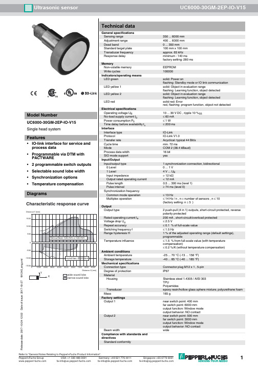
一般说明 检测范围 调节范围 盲区 标准目标板 换能器频率 响应延时
工作方式 / 显示方式 LED 绿色
LED 黄色 1
LED 黄色 2
LED 红色
电气连接
Քጚࡽޙ0থ: (version E6, pnp)
1 (BN)
5 (GY)
U
2 (WH)
4 (BK) 3 (BU)
၍ႊჿࢇޙEN 60947-5-2
常亮:通电 闪烁:待机模式或设定状态下检测到目标物 常亮:开关状态开关输出 1 闪烁:设定功能 常亮:开关状态开关输出 2 闪烁:设定功能 常亮:温度 / 设定插头未连接 闪烁:出错或设定状态下未检测到目标物 温度补偿,开关点设定,输出功能设定
10 ... 30 V DC, 纹波 10 %PP ≤ 50 mA
A2 (N.C.) ਸ࠲ 2 3. ውࢫఇ๕ A1,A2ᅜࢻ࣑ A 1 (N.O.) ਸ࠲ 1
A2 (N.C.) ਸ࠲ 2
附件
BF 5-30
安装附件
BF 30
安装附件
注: 如果不需要使用同步功能,同步输入端必须接地 (0 V) 或者使用 V1 连接器 (4 针 )。
出厂设置
插头位置
功能
ၚᆌ༬Ⴀ൸၍
A1
设定开关点 A1
ਐ Y [m] 0.6
A2 E2/E3 T
设定过程说明
设定开关点 A2 设定工作模式:开关点模式 / 窗口模式 / 迟滞模式 温度补偿
0.4
0.2
0.0
2
1
-0.2
设定开关点 1 或 2 - 切断电源 - 拔下设定插头 - 再次通电 (重启) - 把目标物放置在所需的开关点上 - 把插头插入对应的 A1 或 A2 位置再拔出,开关点 A1 和 A2 就设定完成了。
ມ-LED ୴/ࢤ
LED !!!!ࣜ
E2
E3
A1
A2
ਸ࠲!1
"ཚ"ۉ/߅ඡ
ਸ࠲!2
RS 232-থ੨
ӈ֣
࿒܈/Պ֭ײཀྵ
(ᆯথ੨ۉમ
UC-30GM-R2 থPC)
41
1: TXD 2: RXD 3: փᆩ 4: ں
32
V15-֭ཀྵ (M12x1)
LED-ش੨
注意: 拔出温度 / 设定插头的同时,目标物位置值将被保存 - 设定过程可由 LED 灯指示。绿灯闪烁时,目标物被检测到;红灯闪烁时,目标物
未被检测到。 - 将设定插头插入 T 位置,设定过程结束,传感器进入正常工作模式。
设定输出功能 - 切断电源 - 拔出设定插头 - 再次通电 (重启) - 将设定插头插入 E2/E3 位置,通过多次拔插,可循环地设置三种不同的输出模式:
2 个开关量输出 pnp,¨NO/NC 可选 ≤ 0.1 % 满量程值 200 mA, 短路保护 / 过载保护 ≤ 2.5 V ≤ 2.5 Hz 可调整开关距离的 1 % (缺省设置),可调 ≤ 满量程值的 2 % (带温度补偿) ≤ 0.2 %/K (不带温度补偿)
IEC / EN 60947-5-2
A1: A2:
盲区 最大量程
BF 30-F
安装附件
M-105
安装附件
UVW90-M30
导向板
UVW90-K30
导向板
UC-30GM-TEMP
附件
UC-30GM-PROG
附件
ULTRA3000
软件
UC-30GM-R2
附件
Release date: releasedate Issue date: 2007-10-09 102159_CN.xml
超声波传感器
外形尺寸
5
UC2000-30GM-E6R2-V15
M30x1.5 36
94
22
型号
UC2000-30GM-E6R2-V15
特性
• 通过可编程接口使用 ULTRA 3000 软件进 行传感器参数设定
• 2 个开关量输出可自由调节 • 迟滞模式可选 • 窗口功能可选 • 同步功能 • 声功率和灵敏度可调 • 温度补偿
同步输入端
传感器有一个同步输入端可以抑制传感器之间的相互影响。如果同步输入端不接, 传感器则根据内部产生的时钟频率工作。在传感器的同步输入端上加载一个脉冲宽 度大于 100 μs 的方波脉冲,可以实现同步工作。同步输入端上的同步脉冲启动一个 测量周期,测量周期由同步脉冲的下降沿触发。持续时间大于 1 s 的低电平或者同 步输入端开路,传感器则根据自身内部频率工作。