TECH2WIN软件下载安装指导
时速s2软件重装教程
时速s2软件重装教程时速S2软件重装教程一、准备工作•确保备份好重要文件•确保有稳定的网络连接•准备一个可靠的电源供应二、下载所需软件1.打开浏览器,访问“时速S2官方网站” (在此不提供具体网址,请自行搜索)2.寻找软件下载链接并点击进入3.根据自己设备的操作系统选择合适的版本进行下载三、备份重要数据1.连接设备到电脑上2.打开设备文件管理器(如Windows上的资源管理器)3.找到需要备份的文件夹或文件4.将文件夹或文件复制到电脑上的安全位置四、清除设备数据1.打开设备设置界面2.搜索并点击“系统设置”3.找到“恢复出厂设置”或类似选项4.确认进行恢复出厂设置,并等待设备重启五、安装重装所需软件1.打开下载的软件安装包2.根据提示点击“下一步”或类似选项3.阅读并同意软件许可协议4.选择安装路径并点击“安装”六、连接设备进行重装1.将设备连接到电脑上2.打开安装好的重装软件3.跟随软件界面提示,选择设备连接方式为“USB调试模式”4.等待软件识别设备并显示设备信息七、选择重装系统镜像1.在软件界面选择“系统重装”2.选择合适的系统镜像版本(根据个人需求选择)3.下载系统镜像文件并等待完成八、进行系统重装1.在软件界面点击“开始重装”或类似选项2.确认重装操作并等待过程完成3.不要断开设备连接或关闭软件九、重装完成1.等待软件重装完成的提示2.关闭重装软件并断开设备连接3.打开设备并根据提示设置初始设置4.使用备份的数据恢复个人文件通过以上步骤,你已经成功进行了时速S2软件的重装。
希望这份详细教程对你有所帮助!十、常见问题解决1. 重装过程中设备无法连接电脑怎么办?•确保USB数据线连接可靠且没有松动•尝试更换不同的USB端口•确保电脑上已经安装了设备驱动程序2. 重装过程中出现错误提示怎么办?•首先尝试重新启动电脑和设备,然后再次进行重装操作•网上搜索错误提示的解决方法,尝试根据提示进行修复•如果问题仍然存在,建议寻求专业的技术支持3. 重装后设备无法正常启动怎么办?•尝试进行硬件重启,即长按设备电源键直至设备关闭,然后再次启动•如果问题仍然存在,尝试恢复出厂设置并重装系统•如果问题仍未解决,建议联系设备制造商或寻求专业的技术支持4. 如何避免重装软件出现问题?•在进行重装之前务必做好数据备份,避免重要文件丢失•仔细阅读软件的使用说明和注意事项,确保操作正确•如果不确定如何操作,建议寻求专业人士的帮助或咨询设备制造商的技术支持以上是一份详细的时速S2软件重装教程,希望能够帮助到你。
Windows平台 NS-2 软件安装简明教程
Windows平台NS-2软件安装简明教程Liyang Liuliyangliu@/Documents/ns_setup.pdf本文旨在介绍NS-2软件在Windows平台的安装过程,使广大NS-2用户在最短的时间内了完成软件的安装,本文参考了网络上相关文章,并进行了实际验证,确保所述的安装过成正确、有效。
1.引言NS-2是一款常用的网络模拟软件,它诞生于*NIX环境下。
如果要在Windows环境中进行安装,则需要借助第三方的虚拟软件工具,在Windows平台中可以采用虚拟软件如Vmware先行安装UNIX/Linux操作系统,然后再在虚拟机中进行NS-2的安装。
本教程介绍的是采用Cygwin在Windows下如何安装NS-2软件。
2.安装过程首先到Cygwin的官方网站下载安装程序,大家可以到Cygwin的中国镜像网站1去下载。
在此,我建议大家采用Cygwin本地安装的方式进行,因为网络方式安装通常速度较慢,而且容易出现一些莫名其妙的错误。
可以在搜索引擎中搜索Cygwin镜像文件,本教程中采用的Cygwin镜像下载地址为:ftp://soft:Coolersky@:19527/iso/cygwin2.510.2.2.iso 将上述文件下载后,可以通过虚拟光驱软件(如DAEMON Tools)打开,如图,然后双击setup.exe进入安装界面1安装方式选择本地目录可采用系统默认的设置不必修改,如下图选择本地镜像文件中的文件目录,本演示实例的目录为:http%3a%2f%%2fsourceware%2fcygwin 如图,接下来的这一步比较关键,如果少安装了某些组件,可能会无法编译导致安装失败,点击View键切换浏览模式,需要的组件为:gccgcc-g++gnuplotmakepatchperltarX-startup-scriptsxorg-x11-basexorg-x11-binxorg-x11-develxorg-x11-bin-dllsxorg-x11-bin-lndirxorg-x11-etcxorg-x11-fencxorg-x11-fntsxorg-x11-libs-dataxorg-x11-xwin组件选择好后,点击下一步开始安装,这个过程持续的时间较长安装好后,提示至此完成了Cygwin的安装,接下来就是要在Cygwin环境下进行NS-2软件的安装,建议新手安装NS-2的时候采用allinone的安装包,本教程采用2.29版,下载地址:/nsnam/dist/ns-allinone-2.29.tar.gz下载后,将压缩包放在C:\cygwin\home\YOUR_PATH (YOUR_PA TH为用户名的实际路径)。
安装GTWIN软件
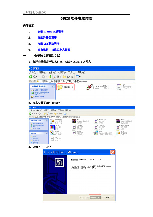
GTWIN软件安装指南内容提示1、安装GTWIN2.2版程序2、安装升级包程序3、安装USB驱动程序4、语言选择,切换至中文界面一、先安装GTWIN2.2版1、打开安装程序所在文件夹,双击GTWIN2.2文件夹2、双击安装图标”SETUP”3、点击“下一步“4、点击“是”5、输入序列号“AIGT8001V2-MEW1374”6、点击“下一步”7、点击“下一步”8、点击“下一步”9、点击“不,稍后再重新启动计算机”,并点击“完成”二、安装升级包返回顶部1、打开安装程序所在文件夹,双击升级文件“gtwin_spv298e”2、出现安装进程对话框,请耐心等待3、出现卸载低版本软件提示,点击“确定”4、点击“开始”菜单----点击“控制面板”5双击“添加/删除程序”6、找到“GTWIN”7、点击“更改/删除“8、出现确认文件删除提醒,点击“确定”9、出现确定删除提醒10、勾选“不再显示此信息”,并点击“是”12、打开安装程序所在文件夹,再次双击升级文件“gtwin_spv298e”13、点击“下一步”15、、输入序列号“AIGT8001V2-MEW1374”16、点击“下一步”17、点击“下一步”18、点击“下一步”19、点击“否”20、点击“完成”,计算机重新启动后,安装完成。
三、安装USB驱动程序返回顶部1、接通触摸屏电源,连接好触摸屏至计算机的USB通讯线,出现找到新硬件提示2、点击“从列表或指定位置安装(高级)”,并点击“下一步”.3、选择“在搜索中包括这个位置(0)”,并选择“浏览”,4、选择“本地磁盘(C:)--program Files—Panasonic EW Terminal—GTWIN—GTWIN “USB”,并选择“确定”。
5、点击“下一步”。
6、选择“Panasonic GT USB Driver Ver.1.0 未知 Panasonic.EW.Autonmation c:\program files\panasonic ew terminal\gtwin\gtwin_usb\gtusb.inf”,并选择“下一步”。
国二软件安装步骤
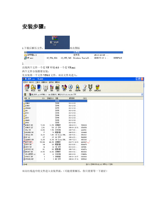
安装步骤:
1.下载后解压文件:双击图标
2.
出现两个文件一个是VF环境6.0一个是VF.msi
两个文件分别都要安装:
先安装第一个文件VF6.0文件,双击文件夹进入:
双击红线选中的文件进入安装界面:(可能需要解压,你只需要等一下就好)
单击下一步:
选择”接受协议“后下一步:
请输入产品的ID号:输入10个1后单击下一步:
路径不需要改,也就是说这一步不用做修改:单击下一步就可以了:
如果有出现这样的提示的话,选择”更多“中的“允许程序所有操作”这一项:可反复选择如果没有出现就进行下一步就可以了~~~~
***选择继续
****选择确定
****选择确定
选择”典型安装“
右下角会出现这一项:只要等到100%就可以了~~~
****选择确定
最后会出现这一对话框,记住单击”退出“
选择”是“第一个文件安装成功了!!!!
第二个文件:双击红线选择的文件:(可能需要解压,你只需要等一下就好)
选择下一步:
序列号框中输入:0003513后单击下一步:
这一项不做修改选择下一步:
选择安装:后安装成功了,在桌面就应该有图标了!!你就可以练习了!!别忘了好好练习呀~~~~~~~~~~~~~。
Help Desk Ultimate 2 安装指南说明书
hHelp Desk Ultimate 2Installation manualTo install the extension follow the instructions below:1) Backup your web directory and store database●Get the Help Desk Ultimate 2 name and version in your Marketplace account:Login to Magento Marketplace with the username and password you used to purchase the Help Desk Ultimate 2 extension;●Enter the My Purchases section: Y our name (top-right corner of the page) > MyProfile > My Purchases;●Find Help Desk Ultimate 2 and click T echnical details.2) Copy the provided component name and version in order to update your composer.json file. Note:W e advise you to use the latest version of our extension.3) Update your composer.json file:●Open the root Magento directory on your server and send Composer the followingcommand:Composer require <help_desk_ultimate>:<version>4) At the Composer request, enter your Magento marketplace credentials (public key - username, private key - password).5) Make sure that Composer finished the installation without errors.6) Flush store cache, log out and log in the backend again.The Help Desk Ultimate 2 extension is now installed and ready for work.Use Magento D ev Docs for more detailsMigrating tickets from Help Desk Ultimate (version 1.*.*) for Magento 2Read carefully and consider this information of top priority. Otherwise it might result in an accident data loss.Prior to migrating tickets accumulated with Help Desk Ultimate for Magento 2, mind the following:●Backup your Magento 2 database to be able to revert changes, if need be.●Tickets can only be migrated from Help Desk Ultimate (version 1.*.*) for Magento2. If your Help Desk Ultimate is for Magento 1, find the instructions h ere.●Data of Help Desk Ultimate (version 1.*.*) for Magento 2 are not deleted from thebase, you can delete the data manually, if needed.●You can run migration multiple times.●Automations cannot be migrated. Custom automations should be reconfiguredafter migration.●Starting with version 2.3.6 of Magento 2, XML files can’t be downloaded. As aresult, tickets from Help Desk Ultimate (version 1.*.*) for Magento 2 with XMLfiles attached won’t migrate to Help Desk Ultimate 2 for Magento 2 if themigration takes place on Magento 2 version 2.3.6 or higher.To migrate tickets to Help Desk Ultimate 2, execute the following command in the console:bin/magento aw-helpdesk2:run-migrationThe following two arguments are available for the command:--limit (-l) [number]Use the above to limit the number of tickets to be migrated in one run (default value is 1000). --clean (-c)Use the above to truncate the Help Desk Ultimate 2 database tables before migration.To migrate next bulk of tickets, run the command again, this time without the -c argument. Check logs to see additional detailsExamples:1)bin/magento aw-helpdesk2:run-migration -cMigrate the default 1000 tickets and clean up the database.2) b in/magento aw-helpdesk2:run-migration -c -l 500Migrate 500 tickets and clean up the database.Set up cronThe Help Desk Ultimate 2 extension uses cron to insert emails from the gateway into tickets and to send notification emails to customers.If you have already configured cron jobs for your Magento installation, then you can skip this step, otherwise refer to the instructions below:In the SSH console of your server, run the following command:crontab -eAnd insert the following line:*/3 * * * * php -c <ini-file-path> <your Magento installdir>/bin/magento cron:run*/3 * * * * php -c <ini-file-path> <your Magento installdir>/update/cron.php*/3 * * * * php -c <ini-file-path> <your Magento installdir>/bin/magento setup:cron:runConfirm the Save request on exit.More on setting up cron job for a Magento store: M agento user guide.。
Win10 TH2正式版下载及激活相关

SHA1:39C08E2D0E76674C8DB0C383D47C02DC435B928B
官方除了订阅中心,公开本地地址还没...
企业版KMS: NPPR9-FWDCX-D2C8J-H872K-2YT43
RTM LTSB: WNMTR-4C88C-JK8YV-HQ7T2-76DF9
家庭版KMS:TX9XD-98N7V-6WMQ6-BX7FG-H8Q99
教育版KMS:NW6C2-QMPVW-D7KKK-3GKT6-VCFB2
cn_windows_10_multiple_editions_version_1511_x64_dvd_7223622.iso
SHA1:9B71AD5604B3816BCC7E9AFA3052AE7D823163E8
发布时间:2015-11-12 文件大小:3.9GB
ed2k://|file|cn_windows_10_multiple_editions_version_1511_x64_dvd_7223622.iso|4187224064|FE3F221D193FEF02627F7F8CF0041BB3|/
ed2k://|file|cn_windows_10_multiple_editions_version_1511_x86_dvd_7223635.iso|3175995392|55D8EF251EEF617DE4D69B54E17B3625|/
Win10 TH2正式版64位简体中文版(含家庭版、专业版)
教育版:供学校使用 (学校职员、管理人员、老师和学生) 其功能几乎和企业版一样,针对学校授权而已;
TECH2 系列安装手册说明书

TECH2 Series Installation ManualTechmation Co. Ltd.9F No. 529, Chung Cheng RoadHsin-Tien CityTaipei, Taiwan R.O.CTel : (02)2218-1686Fax : (02)2218-1766Email:*************************.tw********************.twNingbo, Mainland ChinaTel : (0574)87801426/87803022Fax : (0574)87807389Email:*********************.twHu-Men, Mainland ChinaTel : (0769)85182584Fax : (0769)85182587Email:********************.twCONTENTS1.TECH2 STANDARD USAGE (3)2.1T HERMOCOUPLE (7)2.2T EMPERATURE INCREASE CONTROLLER (8)3. SWITCHING POWER SUPPLY INSTALLATION (10)6. OPERATION PANEL INSTALLATION (25)8. PROPORTION V ALVE INSTALLATION (27)8.P OTENTIOMETER AND P RESSURE S ENSOR I NSTALLATION (28)9. MOTOR START CIRCUIT DIAGRAM (30)9.1Y-Δ START (30)9.2S TRAIT START DIAGRAM (31)1.TECH2 STANDARD USAGEThe installation for TECH2electricity control system is very simple, and the function of the control system is complete. Nevertheless, to prevent the life of the system end fast, the customer must follow the standard usage that is set by the company. Please refer statements below:1. The temperature for rack must be in the range of 0℃ ~ 40℃. The higher the temperature, the shorter thesystems life; and the differences of the potentiometer position can reach up to 0.8mm. It is recommended to fix a fan near the main controller switching power supply, and another one near the SSR.2.For temperature control, can use electromagnetic contactor or SSR (refer to the customers outfit). SSRheater sink should be not more than 65℃ or 75℃, and can’t use more than 5 minutes.3. Is required to use thermocouple type K. When installation, try not to tie together with strong electricparts. (This is regarding the accuracy and temperature stability)4. The fuse for SSR protection must be used according to the specification:a). power below 10A (consist of 10A) : use 10A fuse.b). power above 10A and below 20A (consist of 20A) : use 20A fuse.c). power above 20A : purchase according to the size of the fuse.5.Input voltage for switching power supply is 230V or 115V (there is a switch at the side of power supplyfor selecting). Please note that, if using voltage 115V/60HZ, should convert it from 220V to 110V with DC/DC converter.6.Our company is using a standard the fuse depends on the usage.7.Must strictly avoid the main CPU board from being damaged by water or oil.8.Transistor output board strictly prohibited 1 output point for 2 valves, but is allowed to connect a SSR.9.Our company is using a thin and clear panel screen. Therefore, it’s strictly prohibited to use highevaporate cleaner (etc. petrol, alcohol) to clean the screen. It is recommended to use kerosene and wax (the best suggestion) as cleanser.10.After the installation, must avoid any wire related to computer system broken (except thermocouple),and short circuit with machine outer case. Switching power case will have slightly electric leakage.Therefore, we insist to do ground connection.11.Proportion system normally can control the output of voltage or power (a standard tools for powercontroller). Power is set as 0.8A pressure and 0.7A flow.12.A standard SSR should be type NPN, using H24V and HCOM power supply system.13.The installation of potentiometer should avoid oil sludge pollution. If not, it will course the innerconnection of the potentiometer not sensitive or wire harden and broken.14.The location of the siren must be 20cm from the panel, 40cm from main controller.15. For the electromagnetic contactor that is used by the machine, must fix a spark quencher parallel to thecoil.16. Use SSR if is not using transistor output as controller, should fix a reverse diode parallel to the coil.17.There is a LCD on the operation panel. When installing, must be careful to avoid collide. If need toinstall or change the program (MMI display operation program), be careful of the high voltage at the back of panel when you open the cover.18. When fixing the power, please use iron board. If need to use bakelite plate, must make sure the groundconnection is done properly. This is to prevent electric leakage and electric static interference from damaging the PCB.This standard usage has to coordinate with the following installation manual. When the standard regulation is followed, this will guarantee the quality of the computer.MAIN CONTROLLER MEASUREMENT DRAW2. Temperature Controller InstallationIt consists of A. Thermowire and B. Temperature Increase Controller2.1 Thermocouple1. Thermocouple must be fixed on the Thermo Couple Input block, OIL as oil temperature. Follow the +veand –ve pole of 1-6 parts in thermocouple to fix the TC1-TC6. Don’t connect the thermocouple through many connectors. This will prevent from bad connection and affect the accuracy of the temperature. 2. When the remaining thermocouples are not used, please set the temperature parameter on the HMI to the not use selection (Refer to the HMI Operation Manual). 3. Please connect the thermocouple wire to the +ve and –ve pole to avoid the incorrect value on the controller that might lead the incorrect movement.(The draft below is one of the parts in the main controller)25P Cable (Double Shield)Thermo Couple InputFROM TMPEXTAT 1010-TPV +TPVFrom T1015 output11-7+CN13-8-OIL-6-3+6+9-9+OIL+4-2+TMPEXTA5+2-8+5-7-1+4+PCNX1PTC12.2 Temperature increase controllerTemperature increase controller uses A. SSR (Solid State Relay) or B. Magnetic Contactor2.2.1 SSRFrom the main controller RELAY OUTPUT connect straight to controller. Please be careful of the AC terminal and DC terminal. (DC terminal is the +ve and –ve pole, see below),2.2.2 Electromagnetic contactorIf you are using electromagnetic contactor as the temperature controller, please use RELAY to control the contactor. And fix a spark quencher parallel to the contactor coil. (Refer below)3. Switching Power Supply InstallationThe power supply for this system uses 3 groups of switch power supplies with 110V AC/220V AC options.A.For TECH2 main controllers, +5V, +12V, -12V DC/DC converter.For operation panel +5V, +12V DC/DC converter. Pressure proportional valve input voltage.B.For TECH2 controller VALVE output and LIMIT(SW-150-48), as picture below:C.For TECH2 controller flow proportional valve input voltage, (DCH40NB)as picture below:3.1 Reminder when using switching power1. If the switch power input is short; you must amend the switch power with:a. Varistor (20N 471K)b. Separate transformer: transformer voltage input could use many kind potential inputs and twopotential outputs (AC115V, AC230V,or AC115V/230V).c. EMI Filter (250V AC, 50/60Hz, 3A)Please refer to the suggestion below to prevent the power supply break down.2. FG for switching power supply must be ground connected. This is because, switching power supply might have slightly electric leakage, and this will disturb the system. Therefore, must prepare for ground connection no matter during fixing or using.(please refer chart below)4. The T1015AS transformer (for temperature controller) and the potentiometer are used together;Temperature controller uses yellow-green-yellow 3P wire, straight intoPCNXI(Beside thermocouple input terminal) at the main controller CPU board;Potentiometer controller uses blue-black-blue 3P wire straight into PCN1. (Refer to below):4. Operation Panel Q8 Color panel dimensionV8 Color panel dimensionM10M Color panel dimension5. Directional Valve and Output Installation1. This system provides 32 point DC24V director valve controller. The highest power each pointcan supply is 2A. It is not allowed to connect 2 directional valves at 1 point. If have to do so, please connect the RELAY to the controller and the shared point is H24V . If there is a load or misconnection of wire, switching power will be shut down automatically so it will not spoil the transistor. After repair the failure, please restart the switching power and the machine will run normally.VALVE OUTPUT2.RELAY output, main controller board provides 16 groups of RELAY contact point for customer usage. These include circuit for motor start , motor stop , Y-∆ converter , robot, heater controller etc.L 652(T C R 5)YL 1(T C R 6)S C53A53(T C R 4)54A54A C O 55AL 5L 2A C I N(T C R 1)L 455(T C R 2)(T C R 3)M O T .O F FL 3M O T .O N 52AL 7(T C R 7)L 8(T C R 9)L 9(T C R 8)6. Operation Panel Installation1. Please do not press on the flat cable at the back of the operation panel. It will cause the inner wire broken2. There is a DC/DC converter +5V , +12V circuit line in the PCB (PCB is on the operation panel) for LCD and HMI usage. Connect the DC24V (blue and black) to switching power supply.3. There are 2 white cables on the panel, must connect to setting key . If not, you can’t set the information. The 2 blue lines are for RESET, can be leaved on it self. You can fix the emergency stop as electrical emergency stop . (refer chart below)4. Please connect a line for ground connection from the panel to the copper board白白藍藍資料鎖定鍵緊急停鍵DATA SET EMERGENCY STOP BLUEWHITE WHITEBLUE資料重置DATA KEYRESET7. LIMIT Installation1.This system provides 32 input points.2.If using Limit, the shared power supply point is HCOM. When Limit works, HCOM will input signal.3.Power source for proximity sensor (type NPN) are H24V and HCOM, the signal for action is0V(HCOM).If there is other outer signal, must use low watt proximity sensor (This is because proximity sensor sink current is very low, can’t afford the high power device).If there is a COIL, must connect an opposite direction diode for protection.The arrangement is as below.8. Proportion Valve InstallationPCN4 3P connector (on the main controller CPU) is fixed to the switching power supply. On the other hand, CNDA2, CNDA3, CNDA4, CNDA5 outputs to proportion valves (manufactured by YUKEN, DIKEN etc.) are used to monitor the current meter at the proportion valve. To adjust the P 1-MAX, P 2-MIN, F 1-MAX and F 2-MIN rectificationF 2-F 2+P 2-P 2+F 1-F 1+P 1-P 1++24V C O M +H VP 1V +F 1V +C O M C O M P 2V +F 2V +CND1CND5CND4CND3CND2MIN P 2F 2P 1F 1MAX8. Potentiometer and Pressure Sensor InstallationA/D board is the interface for potentiometer. It converts the voltage, big and small changes (analog/similar) reading from potentiometer to digital signal, to enable CPU to read it. This A/D board can control 8 types of potentiometers, which is the injection, mold clamping, and lastly ejectionPotentiometerSIGNALIn the main controller, the potentiometer uses 3P power supply plugs. At the connector point as shown above, the PC board has 3P plugs and the 2nd pin must be connected to the signal output pin. Normally, the potentiometer prolongation has the biggest value and the back contract has the smallest value. If the direction reverses, the potentiometer 1st and 3rd pin of the plug will be immediately changed (it changes the +ve and – ve pole). Keep in mind not to disconnect the signal; else it will cause the damage to PC board or potentiometer.Please refer to operation manual for potentiometer reset. Choose the length of potentiometer longer than the machine length to avoid being pulled apart.9. Motor Start Circuit Diagram 9.1 Y-Δ startTECH2 Series Installation Manual 9.2 Strait start diagramTechmation Co., Ltd. 31。
gtdesigner2安装教程
gtdesigner2安装教程GTDesigner2安装教程简介•GTDesigner2是一款功能强大的图形界面开发工具,用于创建和编辑人机界面(HMI)应用程序。
本教程将帮助您安装GTDesigner2并快速上手。
步骤1.下载安装程序–打开浏览器,搜索“GTDesigner2下载”。
–找到官方网站并转到下载页面。
–在下载页面找到适用于您操作系统的最新版本的安装程序。
–单击下载按钮开始下载安装程序。
2.运行安装程序–找到您下载的安装程序,双击运行。
–如果操作系统弹出安全提示,请选择“运行”以继续安装。
3.选择安装路径–在安装向导中,您将被要求选择GTDesigner2的安装目录。
–默认情况下,建议选择默认路径,您也可以选择其他路径。
4.进行安装–单击“下一步”继续安装。
–阅读并接受最终用户许可协议。
–选择要安装的组件和功能,然后单击“下一步”。
–等待安装程序完成安装过程。
5.运行GTDesigner2–安装完成后,您可以在开始菜单或桌面上找到GTDesigner2的快捷方式。
–双击快捷方式以启动GTDesigner2。
6.注册产品–在首次运行GTDesigner2时,您将被要求提供产品密钥或激活码。
–根据您的购买方式,输入相应的密钥或激活码完成产品注册。
7.开始使用GTDesigner2–一旦成功注册,您可以开始使用GTDesigner2创建和编辑人机界面应用程序了。
–您可以参考官方提供的文档和教程,探索GTDesigner2的功能和特性。
结论通过本教程,您已经学会了如何安装GTDesigner2并开始使用它。
祝您在创作过程中取得良好的效果!GTDesigner2安装教程(续)更新版本•如果您之前已经安装了GTDesigner2,并希望升级到最新版本,可以按照以下步骤进行操作。
1.下载更新程序–打开浏览器,搜索“GTDesigner2更新下载”。
–找到官方网站并转到下载页面。
–在下载页面找到适用于您操作系统的最新版本的更新程序。
信息技术沪科版计算机应用软件的安装

每周一学:美图秀秀
美图秀秀是一款很好用的国产免费图片 处理软件,操作比较简单,不需要有专业计 算机技术便可以轻松使用。美图秀秀独有的 图片特效、人像美容、可爱饰品、文字模板、 智能边框、魔术场景、自由拼图、摇头娃娃 等功能可以让用户短时间内做出影楼级照片。 美图秀秀还能做非主流闪图、非主流图片、 QQ表情、QQ头像、QQ空间图片等。
一、计算机应用软件的卸载
1.通过“开始菜单”运行 该软件自带的卸载程序。
2.使用“控制面板”中的 “添加或删除程序”。
二、计算机应用软件的安装
1.互联网下载安装软件。 2.找到已下载的软计算机的正常运行。 应用软件:使计算机的功能更强大、
微软Windows系统安装Scratch2.0版本教程

微软Windows系统安装Scratch2.0版本教程
要想使用Scratch2.0版本的软件进行编程,我们需要安装两个软件:
一、Adobe AIR
二、Scratch2.0
这两个软件的安装包都在这个文件夹中
1、我们先来安装Adobe AIR,鼠标左键双击“AdobeAIRInstaller”
2、鼠标左键单击“我同意”
3、等待安装
4、鼠标左键单击“完成”,这样就完成第一个软件Adobe AIR的安装完成了
5、接下来我们来安装第二个软件:Scratch2.0,鼠标左键双击“Scratch-461”
6、选择我们要把软件安装在哪个文件夹,不想选或不会选也可以保持默认(对软件使用没有影响),直接鼠标左键单击“继续”
7、等待软件安装
8、继续等待软件安装
9、鼠标左键单击“Yes,I’d Like To Help Improve Scratch”
10、现在软件就安装完成了,我们可以进行编程了,但是现在的软件界面都是英文,下面我们来把它改成中文的
11、鼠标左键单击小球,会出现一个语言选择列表
12、把鼠标的指针放在列表下方,列表就会滚动起来(下拉),我们让列表滚动到最底部就会出现“简体中文”选项
13、鼠标左键单击“简体中文”
14、现在软件界面就是中文的了,让我们用Scratch2.0进行编程吧!。
ECO2WIN中文使用手册

ECO2WIN中文使用手册目录一、简介1.文档说明2.包含部件3.系统配置要求二、软件安装介绍三、软件运行1.通讯连接和设置2.创建一个新项目3.打开一个新项目4.工作窗口介绍四、软件功能框架1.设备状态(DEVICE STATUS)2.电机控制3.电机控制参数设置4.示波器5.子程序编程(SEQUENCER PROGRAMMING)6.设备配置7.参数直接寻址8.系统管理9.数据输出10.数据载入五、控制器调整六、通信协议说明七、附录1、ECOSTEP技术规格和注意事项2、对象词典参数详细注释3、术语表4、应用范例一、简介1、文档说明此文档专为使用KINCO系列伺服系统所设计,在系统开发过程中请一步步按文档要求执行软件功能。
该文档主要描述的是软件ECO2WIN V2.27的功能。
2、包含部件一张带有ECO2WIN的CD;PEAK公司的CAN-DONGLE(并口适配器)或PCAN-USB(USB口适配器);相关的与控制器间的通讯连接线缆3、操作系统和硬件要求奔腾CPU(最少200MHz)内存大于64MBCD-ROM带有232串口、并口或USB接口WIN98/2000/XP二、软件安装介绍当你将ECO2WIN软件光盘放入光驱中,系统将自动运行安装程序,如下图,请选择“ENGLISH‖语言进行安装:注意,所安装的软件除包含有ECOSTEP相关软件,主要包括ECO2WIN和ECOFLASH,其中ECO2WIN是我们必须安装的ECOSTEP驱动器的控制软件,ECOFLASH是用来下载最新的软件RELEASE。
另外,光盘中还有附加的其它软件,如下图,包括ADOBE 阅读器软件和PEAK系列CAN适配器驱动软件,用户可自行决定是否安装。
注意,如果用户选择基于PEAK公司技术的CAN适配器进行控制,则一定要安装相应的驱动软件(包括并口、USB 口等),见下图:重要说明:当软件在WIN98下安装完毕后,需利用厂家提供的ECO2WIN.INI文件对旧文件进行覆盖后方可工作,WIN2000/XP下无此问题。
HP TechPulse 设备软件部署指南说明书

HP TechPulse设备软件部署指南目录简介 (4)先决条件 (4)将 UPN 后缀提供给 HP 服务专家或业务合作伙伴 (4)下载 HP TechPulse 设备软件 (5)配置代理服务器或防火墙以与 HP TechPulse 通信 (5)HP TechPulse Windows 应用程序的软件先决条件 (5)HP TechPulse Windows 应用程序 (HPTechPulse.exe) (5)HP TechPulse Windows 应用程序(MSI 安装程序) (6)为 HP TechPulse Windows 应用程序配置代理服务器设置 (7)配置代理服务器自动配置 URL (PAC URL) (7)配置静态代理服务器 (7)配置经过身份验证的代理服务器的设置(用户身份验证) (8)配置经过身份验证的代理服务器的设置(计算机身份验证) (9)使用组策略配置代理服务器设置 (9)手动注册 (10)手动注册计算机 (10)安装 HP TechPulse Windows 应用程序 (10)使用公司 PIN 手动注册 Windows 计算机 (10)使用公司 PIN 手动注册 macOS 计算机 (12)使用公司 PIN 手动注册 Android 设备 (12)自动注册 (14)使用序列号自动注册 Windows 设备 (14)先决条件 (14)将序列号导入到 HP TechPulse (14)部署 HP TechPulse Windows 应用程序 (15)使用公司 PIN 自动注册 Windows 设备 (HPTechPulse.exe) (17)使用 Install.CMD 批处理脚本文件进行自动注册 (17)创建 Install.CMD 批处理脚本文件 (17)使用 Install.CMD 文件自动注册 Windows 设备 (18)使用 MS Active Directory (AD) 组策略进行自动注册 (20)使用 Microsoft System Center Configuration Manager (SCCM) 自动注册 (21)使用公司 PIN 自动注册 Windows 设备(MSI 安装程序) (28)使用 Microsoft System Center Configuration Manager (SCCM) 自动注册 (28)使用 Microsoft Intune 自动注册 (45)使用 Jamf Pro 自动注册 macOS 设备 (52)先决条件 (52)脚本 (53)卸载 HP TechPulse Windows 应用程序 (56)手动卸载 (56)故障排除:卸载时取消注册失败错误 (58)通过 System Center Configuration Manager (SCCM) 卸载 HP TechPulse Windows 应用程序 (59)加载卸载脚本 (59)通过将操作设置为卸载来创建部署 (60)使用组策略卸载 HP TechPulse Windows 应用程序 (60)创建组策略对象 (60)删除使用“使用序列号自动注册”方法注册的设备 (61)HP DaaS for Retail (62)HP Retail Peripheral Agent 的先决条件 (62)安装 HP TechPulse 和 HP Retail Peripheral Agent (62)参考资料 (62)其他信息 (63)收集 HP TechPulse Windows 应用程序日志(HPreport 日志) (63)HP 托管服务区域支持 (63)附录 (64)客户端注册命令行参数 (64)HP TechPulse 设备软件部署指南简介可以使用不同选项手动或自动向 HP TechPulse 注册设备。
Tech Tool 2.8 网络更新和安装指南说明书

Guide to TT Network Update & Install (for Version 2.8) General Installation Notes•You must be logged in as “Administrator” or have admin rights to install.•Make sure all Microsoft patches are up to date prior to install.•You must turn off User Access Controls during the install.•Disable all toolbars and pop-up blockers prior to install.•You must have an Internet connection during the install and ensure that firewall and proxy requirements are met prior to the install.•If the machine is locked down by domain policies (folder or registry write permissions, BIOS read, MS-SQL password complexity restrictions, etc), you’ll need to do the install off the domain with these restrictions removed.•Some anti-virus products will view the code used during install as malware, blocking the install. Disable your antivirus prior to beginning the install and re-enable when complete.Firewall OpeningsTech Tool requires that the firewall be open for outbound connections on ports 2010, 80 and 443 for the following URLs/IP addresses:• (IP 153.112.167.191)• (IP 153.112.167.146)• (IP 153.112.163.252)• (IP 153.112.162.194)• (IP 153.112.166.184)• (IP 153.112.167.185)••/ncsi.txt•*o o o o o o o o o Important Note: The development group strongly recommends that access is “permitted by domain name” (*) rather than by IP address in both the firewall and proxy. The above specific addresses are provided (and may change) if your organization’s security policies do not allow this.Proxy RequirementsTech Tool runs as 2 different users: the human that is at the keyboard and LOCAL SYSTEM (i.e., the machine name). This can create connectivity problems with both the central systems and the network update sites, particularly at fleet sites with web filtering proxies and authentication requirements. While PTT provides a means of letting the end user automatically authenticate, it doesn’t allow the LOCAL SYSTEM to do the same. The result is that network updates don’t work, or verification of Internet connectivity fails (no option to “Connect to Central Systems”).There are two methods to fix this problem:1. The LOCAL SYSTEM, i.e., machine name, MUST be allowed to pass through or bypass the proxy without authentication (This may require Active Directory setup and/or proxy rule changes.).2. The “baf” system service can be started with a userid that is allowed to access the Internet without authentication (i.e., not the service tech’s ID).The service tech’s User ID can still be forced to authenticate, so he can’t surf to “less than desirable” web sites. If the proxy software is capable, it may be possible to configure it to allow unauthenticated access to * sites. The proxy must permit access to these URLs (HTTP and HTTPS) for both the service tech’s userid and for LOCAL SYSTEM (or the userid employed to start” baf”):• /* (IP 153.112.167.191)• /* (IP 153.112.167.146)• /* (IP 153.112.163.252)• /* (IP 153.112.162.194)• /* (IP 153.112.166.184)• /* (IP 153.112.167.185)• /ncsi.txt• *Finally, proxied DNS is not supported (PTT must be able to resolve the above URLs directly), and proxy configurations that terminate HTTPS tunnels (man-in-the-middle) and forward after decryption/re-encryption will cause PTT to fail. The application must be allowed to tunnel HTTPS using the CONNECT method for SYSTEM CONTENT.Test URLs (verify that the USER has access through proxy and firewall; there is no means of testing if the MACHINE as LOCAL SYSTEM has access, other than review of drops/denies in the proxy and firewall logs):Using IE, surf to these sites. You should get a splash page or XML code.• – if this fails, you will not be able to log into Central Systems•https:///hmgLite/ws/wsmq?wsdl - if this fails, so will client updates •https:///ping.htm - if this fails, so will client updates•https:///manifests_v21/Diagnostic%20Commu nication%20Database%20(M)%20000.009/master/mastermanifest.xml - if this fails, so will updates•https:/// - if this fails, so will VCADS updates•https://:2010 – if you get a response "401 Unauthorized", means 2010 is enabled. If not, 2010 port is blocked/disabled and you will not be able to login。
gtdesigner2安装教程

gtdesigner2安装教程摘要:1.简介2.安装前提3.安装步骤1) 下载安装包2) 解压安装包3) 运行安装程序4) 安装向导5) 完成安装4.常见问题及解决方法5.总结正文:GTDesigner2 是一款功能强大的绘图设计软件,许多用户想要知道如何安装该软件。
下面,我们将详细介绍GTDesigner2 的安装教程。
首先,我们需要了解安装前提。
GTDesigner2 支持Windows 和Mac 操作系统,要求安装前确保系统版本满足软件的最低要求。
同时,需要预留足够的存储空间以完成安装。
接下来,我们进入安装步骤。
首先,从官方网站或其他可靠来源下载GTDesigner2 安装包。
然后,找到下载的安装包并双击运行,对其进行解压。
解压完成后,你会看到一个名为“GTDesigner2”的文件夹。
打开文件夹,找到名为“GTDesigner2.exe”的可执行文件,双击运行。
这将启动安装向导,引导你完成安装过程。
跟随安装向导的提示,选择合适的安装路径,输入许可证密钥(如需要),并按照屏幕上的说明操作。
安装过程中,软件可能会要求你登录或创建一个账户。
这一步骤并非强制,但如果您想充分利用GTDesigner2 的功能,建议注册一个账户。
安装完成后,你将看到GTDesigner2 的启动界面。
此时,恭喜你成功安装了GTDesigner2!然而,在安装过程中,可能会遇到一些常见问题。
例如,软件无法找到安装路径、无法验证许可证密钥等。
遇到这些问题时,请尝试重新启动安装程序,或查阅官方文档寻求解决方案。
总的来说,GTDesigner2 的安装过程相对简单。
只要确保满足安装前提,遵循安装步骤,遇到问题及时解决,就能顺利完成安装。
通用汽车公司 Tech 2扫描工具 说明书

注意
当电池同时与车辆的12伏点烟器或电源相连时,不要将电池的两个接线端同时接上.因为此时点烟 器中的正负极可能倒置,这将会对Tech 2或车辆造成损害. 如果Tech 2的电源已接通,而显示屏仍为空白,此时点烟器中的正负极可能倒置,这将对Tech 2造 成损害.不要将DLC电缆接到车辆上.确定车辆点烟器的中心触点的电压值高于12伏且外部触点已 接地. 插入或取出PCMCIA卡之前请先关闭电源.建议不要连续取出或重复插入PCMCIA卡. 插入Tech 2之前,请将所有的卡和元件都仔细对齐. 开始使用Tech 2之前,确信所有的电缆和连接器都已连接牢固. 尝试新的程序之前,请仔细阅读说明书. RS-232和RS-485端口不能接到直流电话线上,因为Tech 2的设计不支持这种通讯方式. 放置Tech 2时不要让倾斜支架与车辆电池的接线端接触,这会造成电池短路.
1. 使用:客户只可以在最初安装该软件的计算机系统上使用此软件.未经法律授权,客户不得对该软件进行反汇编或反编译. 2. 所有权:客户同意除了物理介质所有权外,不拥有软件的任何题名或所有权.客户承认并同意该软件的版权归属及其所受的版权法 保护.客户承认并同意该软件可能由版权公告中的第三方软件供应商开发,后者有权要求客户对其任何违反和侵犯版权的行为承担 责任. 3. 终止:当通用汽车公司要求客户遵守协议中的条款,而客户在接到通知后30日内仍未做到时,公司可以终止该软件的授权许可.
图 I-4 T e c h 2 电源和电缆部件编号列表(见第四节)
命令
Tech 2会提示您通过键盘输入以下命令: 获取并查看诊断信息 选择自检 执行车辆诊断程序
ห้องสมุดไป่ตู้
数据存储
Tech 2附带一种名为PCMCIA(个人计算机存储卡业联盟)的卡,用来存储诊断程序.随着车型的不断变 化,重新编写PCMCIA卡的程序并通过RS-232连接器可以随时升级Tech 2的软件.
Windchill10.2-系统安装说明

Windchill 系统安装说明作者:日期:版本:目录1安装规划概述-------------------------------------------------------------------------------------- 3 2安装步骤详细说明-------------------------------------------------------------------------------- 42.1数据库的安装---------------------------------------------------------------------------- 42.2Windchill应用安装 ------------------------------------------------------------------- 132.3安装CPS05 ---------------------------------------------------------------------------- 491 安装规划概述⏹Windchill 安装基本为d:\ptc,Windchill 安装目录是d:\ptc\Windchill,为了管理和维护方便,该目录需要在所有环境中保持一致。
⏹安装时,指定的组织名统一为YS。
⏹安装Windchill之前,需要先安装数据库,安装数据库的时候,只需要安装数据库软件,不能创建数据库实例,数据库实例只能通过OCU来创建。
如果数据库和Windchill安装在不同的机器上,需要先在数据库所在的机器上,使用OCU创建数据库⏹安装用户必须具有管理员权限⏹操作系统版本为Windows 2008 R2 ,数据库版本为11.2.0.3, Windchill 版本为10.2 M030 CPS05⏹安装Windchill ,安装类型为新产品安装,安装CPS05,选择安装类型为更新现有安装。
Tech2Win 安装指南说明书
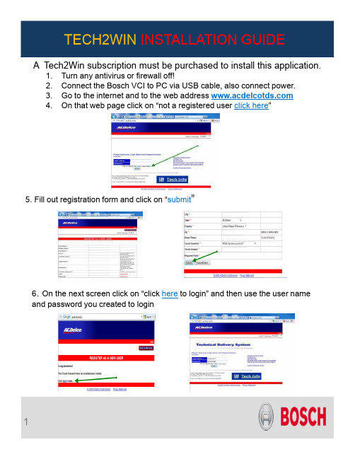
A Tech2Win subscription must be purchased to install this application.1.Turn any antivirus or firewall off! 2.Connect the Bosch VCI to PC via USB cable, also connect power. 3.Go to the internet and to the web address 4.On that web page click on “not a registered user click here ”5. Fill out registration form and click on “submit ”6. On the next screen click on “click here to login” and then use the user name and password you created to login7. agreement, click on “accept” and then click on “service and programing information ”, next screen click on8. Next screen is your choices of subscriptions: For our purpose we will choose the bottom one “Tech2win”. Then pick length of subscription, then fill out form then click on “9.Next screen click on “Access Subscription ” above the subscription that you chose . Next screen click “ ”12. Next screen choose “Software Download (SWDL)” and then click “ Start Software Download “13. Next pop up screen will display “tech2 win not installed” click on “and follow the screen prompts to install tech2win on your PCInstall ”“14. Next screen click “Then you need to minimize the internet screen and click on the ““ icon on your desktop. At this point Connect to your MVCI unit.with thec lick16. Now bring the internet window you minimized back up and choose theoption . Choose “North American operations” ,then the latest version of the software, then “english”, then “select” then “Download”17. Let the program run and then click ““ on the final screen of the installation program and close the internet page. Also close the Tech2win program.18. Reopen the program and the “Select Vehicle CommunicationInterface” screen should pop up, choose how you want to use the program this time. Once you have done that you should be operational!!POSSIBLE ERROR MESSAGESMost error messages are because the programs can not see the VCI.Error messages E4150 one occurs when you are trying to download the program from the internet.● Make sure the Windows Firewall and any antivirus is turned off● Make sure he VCI is powered up and connected via USB cable● Open up the “VCI Manager” on your desktop and see if it see’s the VCI, ifit does it is probably a firewall, if it does not call Bosch Tech support forhelp on resolving the issue.This message occurs wihen you open TECH2winwithout the VCI hooked up and powered on.。
TECH2WIN软件下载安装指导
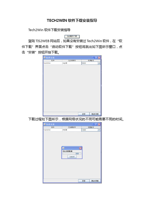
TECH2WIN软件下载安装指导Tech2Win软件下载安装指导登陆TIS2WEB网站后,如果没有安装过Tech2Win软件,在“软件下载”界面点击“启动软件下载”按钮将跳出如下图所示窗口,点击“安装”按钮开始下载。
下载过程如下图所示,根据网络状况的不同可能需要不同的时间。
下载完成后会自动跳出如下图所示的窗口,点击“下一步”按钮继续。
在下图所示的窗口中,勾选“我接受许可协议中的条款(A)”后点击“下一步”按钮继续。
点击“下一步”按钮继续。
点击“安装”按钮继续。
等待安装完成。
过程中会跳出如下图所示的窗口,不要进行任何操作。
点击“完成”按钮完成软件安装。
点击“完成”按钮将回到如下图所示的窗口,点击“OK”按钮完成。
正常情况下,点击“OK”按钮后会跳出下载T ech2数据卡的窗口,如果没有自动跳出,可以点击“软件下载”界面“启动软件下载”按钮调出该窗口。
Tech2Win软件安装完成后会在桌面上生成如下图所示的两个快捷方式。
当出现数据卡下载界面时,点击“Quickstart”图标启动Tech2Win软件。
Tech2Win软件启动过程中,会跳出如下图所示的三个窗口,不必理会其提示,切勿按照提示连接MDI至电脑,否则将导致数据卡文件下载失败。
点击“OK”或“Yes”按钮关闭相关窗口。
Tech2Win软件第一次启动完成后界面将如下图所示。
在数据卡下载界面点选“定制”,点击“下一步”按钮,选择正确的数据卡文件下载。
数据卡文件下载过程与实体T ech2一致。
完成数据卡文件下载后,关闭Tech2Win软件。
将车辆通过MDI 连接至电脑,重新通过双击Quickstart”图标启动Tech2Win软件,将跳出如下图所示窗口,点击“OK”按钮完成软件安装和设置。
安装和设置完成后即可进行相关操作,操作与实体Tech2类似。
- 1、下载文档前请自行甄别文档内容的完整性,平台不提供额外的编辑、内容补充、找答案等附加服务。
- 2、"仅部分预览"的文档,不可在线预览部分如存在完整性等问题,可反馈申请退款(可完整预览的文档不适用该条件!)。
- 3、如文档侵犯您的权益,请联系客服反馈,我们会尽快为您处理(人工客服工作时间:9:00-18:30)。
Tech2Win软件下载安装指导
登陆TIS2WEB网站后,如果没有安装过Tech2Win软件,在“软件下载”界面点击“启动软件下载”按钮将跳出如下图所示窗口,点击“安装”按钮开始下载。
下载过程如下图所示,根据网络状况的不同可能需要不同的时间。
下载完成后会自动跳出如下图所示的窗口,点击“下一步”按钮继续。
在下图所示的窗口中,勾选“我接受许可协议中的条款(A)”后点击“下一步”按钮继续。
点击“下一步”按钮继续。
点击“安装”按钮继续。
等待安装完成。
过程中会跳出如下图所示的窗口,不要进行任何操作。
点击“完成”按钮完成软件安装。
点击“完成”按钮将回到如下图所示的窗口,点击“OK”按钮完成。
正常情况下,点击“OK”按钮后会跳出下载Tech2数据卡的窗口,如果没有自动跳出,可以点击“软件下载”界面“启动软件下载”按钮调出该窗口。
Tech2Win软件安装完成后会在桌面上生成如下图所示的两个快捷方式。
当出现数据卡下载界面时,点击“Quickstart”图标启动Tech2Win软件。
Tech2Win软件启动过程中,会跳出如下图所示的三个窗口,不必理会其提示,切勿按照提示连接MDI至电脑,否则将导致数据卡文件下载失败。
点击“OK”或“Yes”按钮关闭相关窗口。
Tech2Win软件第一次启动完成后界面将如下图所示。
在数据卡下载界面点选“定制”,点击“下一步”按钮,选择正确的数据卡文件下载。
数据卡文件下载过程与实体Tech2一致。
完成数据卡文件下载后,关闭Tech2Win软件。
将车辆通过MDI连接至电脑,重新通过双击Quickstart”图标启动Tech2Win软件,将跳出如下图所示窗口,点击“OK”按钮完成软件安装和设置。
安装和设置完成后即可进行相关操作,操作与实体Tech2类似。