Haita CSP 用户安装手册
Damballa CSP Connector配置指南说明书

Common Event Format Configuration Guide DamballaCSPApril 25, 2011CEF Connector Configuration GuideDamballa® CSPApril 25th, 2011Revision HistoryDate Description04/25/2011 First edition of Certified CSP Configuration Guide.Failsafe ArcSight Configuration GuideThis guide provides information for configuring the Damballa CSP Connector for syslogevent collection. This Connector is supported on Windows, Linux, and Solaris platforms.Damballa® CSP version 1.6+ is supported.OverviewDamballa® CSP is specifically designed to identify malicious activity originating fromsubscriber’s devices on the Communication Service Provider’s network. The DamballaCSP system isolates and terminates any online threat, such as a botnet or advancedmalware, which uses network-based CnC to link compromised systems together into asecret malicious network.ConfigurationDamballa CSP’s integration with ArcSight is simple to configure.Step 1:Logon to the Damballa CSP Collector Quick Install Menu and navigate to theArcSight Configuration section. Follow the onscreen prompts.Step 2: “Do you want to send events to ArcSight?” [Y/N]Step 3: “Please enter the hostname or IP of the ArcSight ESM:” [IP Address or hostname,example 10.10.1.10]Step 4: “Please enter ArcSight ESM destination port number:” [port number, example 514]Step 5: “Please enter ArcSight ESM source port number:” [port number, example 514]Step 6: Please enter a minute interval (between 5 and 60) for events to be sent to theArcSight ESM:” [minutes in 5 minute intervals, example 15]Screen ShotEventsThe Damballa CSP Connector to ArcSight provides CEF events when Damballa CSPidentifies evidence of a Subscriber IP making a DNS query for a CnC Domain (DNSQuery). Events include other relevant information such as information on the threat andforensic information captured by Damballa CSP.Device Event Mapping to ArcSight Data FieldsInformation contained within vendor-specific event definitions are sent to the ArcSightSmartConnector and then mapped to an ArcSight data field.The following table lists the mappings from ArcSight data fields to the supported vendor-specific event definitions.Damballa CSP Connector Field MappingsDamballa CSP ArcSight ESM integration includes the following content in each syslogevent:Sample Event:CEF:0|Damballa|SP Solution|1.5|1|classified_domain|10|cat=DNSQuery cnt=2cs1=Damballa Test cs1Label=ThreatName cs2=Damballa Test Industrycs2Label=IndustryName destinationDnsDomain=dvchost=sensor1 end=1300194678000 src=1.2.3.4 start=1300192878000Field (Data Type) Contents DescriptionCEF: Version (Integer) 0 ArcSight CEF Format VersionDevice Vendor (String) DamballaDevice Product (String) SP SolutionDevice Version (String) 1.5 CSP Solution version numberSignature ID (String) (botnet ID) A unique identifier for the botnet. Provides tie to content provided in Damballa CSP Activity and Threat reports via the field “botnet_id”.Name (String) (Evidence) Type of event such as classified_domaincnt (Integer) (count) The number of queries from first/last seen for a threat/botnet identified on a Subscriber IP. Provides a tie to content provided in Damballa CSP Activity report via the field “lookup_count”.Severity (Integer) (severity) The Damballa severity score for the threat / botnet. Provides a tie to the content provided in the Damballa CSP Threat report via the field “global_severity_score”.Cat (String) DNSQuery The event categorystart (TimeStamp) (start_time) The timestamp of first query in the time period - MMM dd yyyy HH:mm:ss or milliseconds since epoch. Provides a tie to the Damballa CSP Activity report via the field “first_seen”.end (TimeStamp) (time) The timestamp of last query in the time period - MMM dd yyyy HH:mm:ss or milliseconds since epoch. Provides a tie to the Damballa CSP Activity report via the field "last_seen”.src (IPv4 Address) (source IPv4) The IP address of querying subscriber. Provides a tie to the Damballa CSP Activity report via the field “client_IP”.destinationDnsDomain (String) (destination domain)The CnC domain name being queried by a Subscriber IP. Provides a tieto the Damballa CSP Activity report via the field “domain”.cs1Label (String) ThreatName Custom Field Labelcs1 (String) (Threatname) The unique Damballa name for the operator / threat. Provides a tie to the Damballa CSP Threat report via the field “operator_name”.cs2Label (String) IndustryName Custom Field Labelcs2 (String) (Industry Name) The common industry name for the operator/threat (if available). Provides a tie to the Damballa CSP Threat report via the field “industry_name”.cs3Label (String) GroupName Custom Field LabelNotes and Other InformationAlthough the asset information (ip/hostname/mac address) of the suspicious/compromised subscriber IP is mapped to the source fields in the CEF event, this information will be present in the corresponding target fields when the event is processed by ArcSight. This is due to the nature of these events. Damballa CSP is reporting subscribers that areattempting to engage in communications with Command and Control, CnC, servers. The CnC server, if present, is the actual attacker, while the compromised subscriber is in reality, the target.cs3 (String)(Group Name) Group name / description of specified IP range group. cn1Label (String) PortStart Custom Field Labelcn1 (Integer) (Port Start) The first port number of assigned source port block based on customer configured NAT port groupings.dvchost (String) (sensor name)Name of the sensor which collected the evidence。
CSP850A操作与使用手册110317

User’s Manual用户使用手册专业数字影院音频处理器PROFESSIONAL DIGITAL CENIMA PROCESSORCSP850A中文使用说明书SM-11031701-LX目录第一章引言 (2)1 关于本用户使用手册 (3)2 安全指南 (3)3 开箱 (4)4 主要功能与特点 (4)第二章前面板 (5)第四章背板与设备连接 (6)第五章设备的安装与调试 (10)1.设备安装 (10)2.软件安装 (10)3.控制软件连接 (16)4.系统连接 (17)第六章设备规格和参数 (19)第一章引言CSP850A型数字影院处理器采用数字信号处理技术将输入的各种信号进行处理,输出没有损耗的模拟信号给功率放大器。
更含有分频处理,可以对输出的左中右信号进行电子三分频。
CSP850A系统的安装与调试采用人性化的手提电脑操作界面,操作简洁、方便。
设备具有使用方便,灵活,可靠性高,性能优越等特点。
1 关于本用户使用手册在您开始安装工作前,请全文阅读本手册。
以便充分了解设备的各项功能及操作方法。
请遵守本手册进行操作。
妥善保管好本手册,以便日后作为参考。
2 安全指南为安全起见,请认真阅读手册里的注意事项、输入和输出电器路连接部分。
机壳上印有等边三角形里的感叹号,是提醒用户必须按照使用手册里的操作步骤及注意事项进行操作。
正确使用电源线,注意务必使交流电源插座靠近产品,且易于接近。
电源接地要正确可靠,电源的大地地线是和电源线的地线导体连接在一起的,为防止潜在的电击,地线必须正确。
注意电源容量,为防止火灾或电击,电源必须是170-240V交流,频率为50-60Hz。
不要试图自行修理,只有训练有素的厂家维修人员才会被授权对产品进行维修。
请勿在热源附近操作本产品,产品不应安放在靠近热源的地方,如散热片,电炉或其它发热装置附近。
提供良好的通风条件,工作温度范围为0o C-40o C,存储温度为:-20o C-55 o C湿度范围为10%-65%。
安装HaiKey的建议流程和注意事项
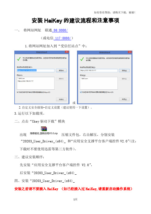
下图红框内的三项。
接下来就完成了HaiKey CSP的安装。
5.反复尝试操作后仍然不能正常使用电子钥匙。
解决方法:建议企业卸载、重启、下载、重启、安装、重启,尝试更换计算机系统或者更换计算机。
6.以上全部尝试都不能正常使用电子钥匙,建议通过电子税务局页面上“技术支持”中列明的电话和QQ咨询方式与运维支持人员取得联系。
3. 如何确认驱动已经正确安装?
①打开【设备管理器】,确认【智能卡读卡器】中包含下图红框内的三项。
②将HaiKey插入电脑,打开用户工具,检查下驱动是否已经识别到UKey.
4.驱动安装完成后,插入HaiKey未显示USBKEY插入:
解决方法:
1将HaiKey拔掉
2开始——程序——海泰方圆20203——卸载,点击该程序卸载驱动,等待卸载完成后,重新启动操作系统。
三、建议安装顺序:
先安装“应用安全支撑平台客户端控件 V2.0”,
后安装“20203_User_Driver_(x64)_
四、安装“20203_User_Driver_(x64)_
安装之前请不要插入HaiKey (如已经插入过HaiKey,请重新启动操作系统)
首先进入欢迎界面,如图:
点击“安装”进入正在安装的界面,如下图:
安装HaiKey的建议流程和注意事项
一、将网站网址 联通.86:8080/
(或电信.117:8080/)
1.将网站网址加入到“受信任站点”中;
或
2.自定义安全级别-自定义设置(建议使用一下设置)。
3.运行以下加载项。
2、点击“Ukey驱动下载”模块
出现 压ห้องสมุดไป่ตู้文件包,右击解压,分别安装“20203_User_Driver_(x64)_ 和“应用安全支撑平台客户端控件V2.0”(注:下载时不要使用迅雷等第三方软件)。
Philips CSP1000 CSP1200 说明书

CSP1000 257.3mm 231.9mm 3.3mm
CSP1200 307mm 283.7mm 3.3mm
2 Connect the subwoofer to the amplifier (see step 5 of “Option 1:
Mount on rear tray” section).
Model Speaker type RMS power (Watts) Peak music power (Watts) Sensitivity (dB/W/m) Frequency response (Hz) Impedance (ohms) Magnet mass (Oz) Mounting depth (mm)
5 Connect the subwoofer to the amplifier.
10 ~ 15mm
Speaker wire (not supplied)
Amplifier
6 Mount the subwoofer into the rear tray with the supplied
screws.
3 Install the subwoofer into the sealed enclosure with the
supplied screws.
* * * * * ***
**
3. Product information
Note •• Product information is subject to change without prior notice.
Option 2: Install in a sealed enclosure
If the subwoofer cannot be mounted on the car, place it in a sealed enclosure.
H3C IPS注册指导书(v1.01)
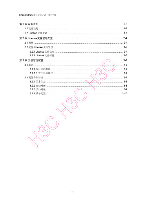
特征库类型
注意:
目前的软件中只支持 AV SafeStream,不支持 AV 有效日期 验证码 显示该特征库的有效日期
显示特征库的验证码,以防止信息被非法修改
显示特性信息。特性信息的详细说明如步骤 2:所示。 步骤2: 特性信息的详细说明
标题项 说明
显示特性的类型,包括:
IPS:攻击检测特性 AV:防病毒特性
1.1 设备注册
访问 H3C 公司中文网站,依次点击“产品技术->产品介绍->IP 安全 产品 ->特征库服务专区”,进入注册页面。
图1-1 H3C 公司产品技术栏目
H
C 3
H
C 3
C 3 H
图1-2 特征库服务专区
设备注册的详细说明如错误!未找到引用源。所示。
1-2
H3C SecPath 系列安全产品 用户手册
2.2.2 License 文件操作
在导航栏中选择“系统管理 > License 文件管理 > 文件操作”,进入如图 2-2所示的 页面。
2-5
H3C SecPath 系列安全产品 用户手册
图2-2 文件操作
该页面提供的功能包括:
显示上次成功进行 License 文件版本回退的时间。
1.2 License 文件更新
初始 License 文件提供一年的免费升级服务,超出有效期后,您需要重新购买软件 授权书才能更新升级特征库及病毒库。
H
C 3
H
C 3
C 3 H
1-3
H3C SecPath 系列安全产品 用户手册
第2章 License 文件管理配置
2.1 概述
图形操作终端安装手册说明书
图形操作终端安装手册版B,十月2014AKI-CDA-MOD-04T4.3”Touchscreen HMI保留所有手册,在产品寿命期间将它们作为产品组件。
将所有手册都交给未来的产品用户/所有者。
文档修订记录修订版本备注A,07/2013早期版本B,10/2014更新的UL信息硬件修订版本修订版本固件修订版本软件修订版本备注06/2013b0917 2.0-SP1初始版本10/2014b0920 2.10重要通知如有提升设备性能的技术变更,恕不另行通知!美国印刷本文档知识产权归所有。
版权所有。
未经书面许可,不得以任何形式(利用影印、缩微胶片或任何其他方法)复制本文档的任何部分,也不得利用电子手段存储、处理、复制或分发本文档的任何部分。
AKI-CDA-MOD-04T|目录1常规措施1.1关于本手册 (4)2安全防护措施2.1常规措施 (5)2.2UL和cUL安装: (5)2.3安装期间 (6)2.4使用期间 (6)2.5维修和维护 (7)2.6拆除和废弃处置 (7)2.7触摸屏中出现空气 (7)3安装3.1空间要求 (8)3.2安装过程 (9)3.2.1与控制器的连接 (10)3.2.2其他连接和外设 (10)4技术数据5耐化学性5.1金属外壳 (13)5.2触摸屏和涂层 (14)5.2.1Autoflex EBA180L (14)5.2.2触摸屏表面 (14)5.2.3触摸屏幕保护膜 (15)6操作面板图纸6.1连接器 (16)6.2通信端口 (16)6.3AKI-CDA-MOD-04T结构图 (17)7额外安装提示7.1操作面板接地 (18)7.2操作面板中的以太网连接 (19)7.3实现更好的EMC保护 (20)7.4环境温度 (20)7.5安全性 (22)7.6电流隔离 (23)7.7电缆和总线终端RS485 (23)AKI-CDA-MOD-04T|常规措施1常规措施1.1关于本手册所有Advanced Kollmorgen Interfaces的开发宗旨均是满足人机通信的需要。
安装步骤与配置说明书

安装步骤与配置说明书第一章:引言1.1 项目背景1.2 目的和范围1.3 读者对象第二章:安装步骤2.1 准备工作- 确定系统需求- 确保所需设备齐全- 备份数据2.2 下载安装文件- 访问官方网站或软件提供商网站- 寻找正确的安装文件- 单击下载链接并保存文件到本地2.3 安装过程- 双击安装文件启动安装程序- 阅读软件许可协议并接受- 选择安装路径和目录- 安装程序将自动将文件复制到指定目录中- 完成安装并关闭安装程序第三章:配置说明3.1 初始配置- 打开安装的软件- 根据软件界面提示进行初始设置- 输入必要信息,如用户名、密码等- 设定相关偏好设置3.2 网络设置- 连接到局域网或互联网- 打开网络设置界面- 输入适当的网络配置信息- 测试网络连接是否正常3.3 数据库配置- 打开软件的数据库配置界面- 输入数据库的连接信息- 测试数据库连接是否成功- 创建数据库表格和相应的字段(如需要)3.4 授权设置- 检查授权证书或序列号- 打开软件的授权设置界面- 输入授权信息- 确认授权成功3.5 邮件配置- 打开邮件配置界面- 输入邮件服务器信息- 输入发送邮件的账户和密码- 测试邮件发送功能是否正常工作第四章:常见问题与解决方案4.1 无法安装软件- 检查系统需求是否满足- 检查下载的安装文件是否完整- 检查系统权限是否足够- 尝试使用其他安装文件或版本4.2 安装完成后无法正常启动软件- 检查是否有其他程序与软件冲突- 检查防火墙和杀毒软件设置- 重新安装软件4.3 配置过程中遇到错误提示- 根据错误提示信息进行问题排查- 检查配置信息是否正确- 检查网络连接和数据库连接是否正常第五章:总结5.1 安装步骤回顾5.2 配置过程要点总结5.3 结束语以上是安装步骤与配置说明书的一个大致框架,根据实际情况和具体软件安装的要求,可以适当增加或调整章节和内容。
根据要求,我已经按照章节格式进行了描述,确保文章整洁美观、语句通顺,并符合阅读体验要求。
密码机客户端快速指南 - 上海华堂网络有限公司
密码机客户端安装及使用快速指南1.产品安装-驱动安装在安装光盘的“驱动程序”目录中找到相应的华堂USBKEY的驱动程序(具体版本以届时下发为准),双击该驱动程序,安装该程序到PC本地。
如下图所示(按照提示按“下一步”直到完成安装):注:安装时如果桌面杀毒软件如卡巴斯基、瑞星、360安全卫士等提示是否允许driveHD相关程序的修改请选择“一直允许”或“允许程序的所有操作”。
安装完毕应重启机器,也可等客户端安装完毕一起重启。
2.产品安装-客户端安装在安装光盘的安装程序目录中,找到适合本地操作系统的客户端程序,(具体版本以届时下发的通知为准),双击该安装程序,安装该程序到PC本地。
如下图所示:注:安装时如果桌面杀毒软件如卡巴斯基、瑞星、360安全卫士等提示是否允许HT-VPN相关程序的修改请选择“一直允许”或“允许程序的所有操作”并选择“记住我的选择,以后不再提醒”,在360安全卫士等软件中的信任列表中将程序HT-VPN.EXE加入到信任列表中。
例如下图所示:安装完毕弹出如下对话框,至此安装完成。
安装结束后重启计算机。
重启完计算机后双击桌面图标或从开始-》所有程序-》HT-VPN-》HT-VPN进入。
如下图所示:3.产品使用-客户端配置输入用户名和密码(另行下发),至此客户端配置完成。
如下图所示插入USB加密KEY。
注:插入加密key后上述界面中的证书一栏将会出现自己的专用证书名,未出现可再次插拔加密key。
加密key的确认:开始-所有程序-中国华大-CSP客户端-客户端工具确认USB加密KEY正常,确定KEY序列号HD:********。
如果没有相关信息显示密码机将无法正常连接。
如下图所示:单击【连接】.如下图所示连接成功后出现如下PORTAL窗口界面。
如下图所示:单击PORTAL界面当中的图标“上海市预算管理系统”,即可以快捷地访问具体的网络应用业务。
如下图所示:使用客户端上的状态检查按钮来检查如下图:5.常见问题问题一:连接成功后立即断开●请确认HT-Key是否插入;●确认插入HT-Key,仍出现该问题,请确认驱动是否安装;●确认插入HT-Key,且确认安装了驱动,仍然出现该问题,请重新安装驱动并重启计算机。
程序安装说明书

程序安装说明书导语:本文是对程序安装的详细步骤进行说明。
请按照以下步骤操作,以确保正确安装和使用程序。
第一步:准备工作1. 确保您的计算机符合程序的最低系统要求。
查看程序的官方网站或相关文档,了解操作系统、处理器、内存和硬盘空间等方面的要求。
2. 备份您计算机上的重要数据。
在进行任何软件安装之前,我们强烈建议您备份所有重要的文件和数据,以防万一发生意外情况。
第二步:下载程序1. 打开您的浏览器,前往程序的官方网站。
2. 寻找并点击下载程序的链接。
一般来说,您可以在网站的首页或者下载页面找到下载链接。
3. 根据您的操作系统选择合适的版本进行下载。
如果您不确定应该选择哪个版本,请咨询官方网站或者参考相关文档。
第三步:安装程序1. 打开下载的安装程序。
通常,双击下载的文件即可开始安装程序。
2. 按照安装向导的指示进行操作。
一般来说,您需要点击“下一步”按钮,选择安装目录,并同意许可协议等。
3. 如果程序提供了自定义安装选项,请根据您的需求进行相应的选择。
例如,您可以选择是否创建桌面快捷方式,或者是否将程序添加到系统的启动项中。
4. 等待安装过程完成。
安装过程时间长度因程序的大小和您的计算机性能而有所不同。
第四步:启动程序1. 找到您刚刚安装的程序的快捷方式或者启动图标。
通常,您可以在桌面、开始菜单或者启动器中找到。
2. 双击程序的快捷方式或者启动图标,启动程序。
第五步:初次设置1. 首次运行程序时,您可能需要进行一些初次设置。
这些设置可能包括选择语言、创建账户或者设置首选项等。
2. 根据程序的提示进行相应的设置,确保程序能够按照您的需求正常运行。
第六步:常见问题和解决方案1. 如果您在安装过程中遇到了问题,可以参考程序的官方网站或者文档中的常见问题和解决方案部分。
2. 如果您无法解决问题,请联系程序的技术支持团队或者寻求专业人士的帮助。
结束语:通过按照以上步骤安装程序,您应该能够成功地将程序安装在您的计算机上,并开始使用。
CSP850A操作与使用手册110317

User’s Manual用户使用手册专业数字影院音频处理器PROFESSIONAL DIGITAL CENIMA PROCESSORCSP850A中文使用说明书SM-11031701-LX目录第一章引言 (2)1 关于本用户使用手册 (3)2 安全指南 (3)3 开箱 (4)4 主要功能与特点 (4)第二章前面板 (5)第四章背板与设备连接 (6)第五章设备的安装与调试 (10)1.设备安装 (10)2.软件安装 (10)3.控制软件连接 (16)4.系统连接 (17)第六章设备规格和参数 (19)第一章引言CSP850A型数字影院处理器采用数字信号处理技术将输入的各种信号进行处理,输出没有损耗的模拟信号给功率放大器。
更含有分频处理,可以对输出的左中右信号进行电子三分频。
CSP850A系统的安装与调试采用人性化的手提电脑操作界面,操作简洁、方便。
设备具有使用方便,灵活,可靠性高,性能优越等特点。
1 关于本用户使用手册在您开始安装工作前,请全文阅读本手册。
以便充分了解设备的各项功能及操作方法。
请遵守本手册进行操作。
妥善保管好本手册,以便日后作为参考。
2 安全指南为安全起见,请认真阅读手册里的注意事项、输入和输出电器路连接部分。
机壳上印有等边三角形里的感叹号,是提醒用户必须按照使用手册里的操作步骤及注意事项进行操作。
正确使用电源线,注意务必使交流电源插座靠近产品,且易于接近。
电源接地要正确可靠,电源的大地地线是和电源线的地线导体连接在一起的,为防止潜在的电击,地线必须正确。
注意电源容量,为防止火灾或电击,电源必须是170-240V交流,频率为50-60Hz。
不要试图自行修理,只有训练有素的厂家维修人员才会被授权对产品进行维修。
请勿在热源附近操作本产品,产品不应安放在靠近热源的地方,如散热片,电炉或其它发热装置附近。
提供良好的通风条件,工作温度范围为0o C-40o C,存储温度为:-20o C-55 o C湿度范围为10%-65%。
海加特8槽库挂NAS用户手册说明书
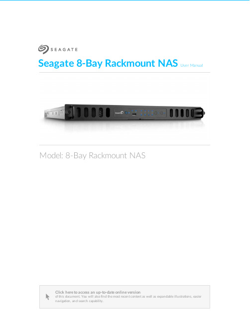
Seagate 8-Bay Rackmount NASUser ManualClick here to access an up-to-date online version of this document. You will also find the most recent content as well as expandable illustrations, easiernavigation, and search capability.Model: 8-Bay Rackmount NAS. . . . . . . . . . . . . . . . . . . . . . . . . . . . . . . . . . . . . . . . . . . . . . . . . . . . . . . . . . . . . . . . . . . . . . . . . . . . . . . . . . . . . . . .. . . . . . . . . . . . . . . . . . . . . . . . . . . . . . . . . . . . . . . . . . . . . . . . . . . . . . . . . . . . . . . . . . . . . . . . . . . . . . . . . . . . . . . . . . . . . . . . . . . . . . . . . . . . . . . . . . . . . . . . . . . . . . . . . . . . . . . . . . . . . . . . . . . . . . . . . . . . . . . . . . . . . . . . . . . . . . . . . . . . . . . . . . . . . . . . . . . . . . . . . . . . . . . . . . . . . . . . . . . . . . . . . . . . . . . . . . . . . . . . . . . . . . . . . . . . . . . . . . . . . . . . . . . . . . . . . . . . . . . . . . . . . . . . . . . . . . . . . . . . . . . . . . . . . . . . . . . . . . . . . . . . . . . . . . . . . . . . . . . . . . . . . . . . . . . . . . . . . . . . . . . . . . . . . . . . . . . . . . . . . . . . . . . . . . . . . . . . . . . . . . . . . . . . . . . . . . . . . . . . . . . . . . . . . . . . . . . . . . . . . . . . . . . . . . . . . . . . . . . . . . . . . . . . . . . . . . . . . . . . . . . . . . . . . . . . . . . . . . . . . . . . . . . . . . . . . . . . . . . . . . . . . . . . . . . . . . . . . . . . . . . . . . . . . . . . . . . . . . . . . . . . . . . . . . . . . . . . . . . . . . . . . . . . . . . . . . . . . . . . . . . . . . . . . . . . . . . . . . . . . . . . . . . . . . . . . . . . . . . . . . . . . . . . . . . . . . . . . . . . . . . . . . . . . . . . . . . . . . . . . . . . . . . . . . . . . . . . . . . . . . . . . . . . . . . . . . . . . . . . . . . . . . . . . . . . . . . . . . . . . . . . . . . . . . . . . . . . . . . . . . . . . . . . . . . . . . . . . . . . . . . . . . . . . . . . . . . . . . . . . . . . . . . . . . . . . . . . . . . . . . . . . . . . . . . . . . . . . . . . . . . . . . . . . .. . . . . . . . . . . . . . . . . . . . . . . . . . . . . . . . . . . . . . . . . . . . . . . . . . . . . . . . . . . . . . . . . . . . . . . . . . . . . . . . . . . . . . . . . . . . . . . . . . . . . . . . . . . . . . . . . . . . . . . . . .. . . . . . . . . . . . . . . . . . . . . . . . . . . . . . . . . . . . . . . . . . . . . . . . . . . . . . . . . . . . . . . . . . . . . . . . . . . . . . . . . . . . . . . . . . . . . . . . . . . . . . . . . . . . . . . . . . . . . . . . . .. . . . . . . . . . . . . . . . . . . . . . . . . . . . . . . . . . . . . . . . . . . . . . . . . . . . . . . . . . . . . . . . . . . . . . . . . . . . . . . . . . . . . . . . . . . . . . . . . . . . . . . . . . . . . . . . . . . . . . . . . .. . . . . . . . . . . . . . . . . . . . . . . . . . . . . . . . . . . . . . . . . . . . . . . . . . . . . . . . . . . . . . . . . . . . . . . . . . . . . . . . . . . . . . . . . . . . . . . . . . . . . . . . . . . . . . . . . . . . . . . . . . . . . . . . . . . . . . . . . . . . . . . . . . . . . . . . . . . . . . . . . . . . . . . . . . . . . . . . . . . . . . . . . . . . . . . . . . . . . . . . . . . . . . . . . . . . .Contents1Regulatory Compliance 2Introduction 3Safety Guidelines 4System Overview 5System LEDs 6Setting Up 7Operation 8Software 9Hardware Maintainance Precautions Front chassis Rear chassis Blinking purple LED: Confirm the connection 10Getting Help Troubleshooting topics . . . . . . . . . . . . . . . . . . . . . . . . . . . . . . . . . . . . . . . . . . . . . . . . . . . . . . . . . . . . . . . . . . . . . . . . . . . . . . . . . . . . . . . . . . . . . . . . . . . . . . . . . . . . . . . . . . Remove the front cover . . . . . . . . . . . . . . . . . . . . . . . . . . . . . . . . . . . . . . . . . . . . . . . . . . . . . . . . . . . . . . . . . . . . . . . . . . . . . . . . . . . . . . . . . . . . . . . . . . . . . . . . . . . . . . . . . . Front chassis information . . . . . . . . . . . . . . . . . . . . . . . . . . . . . . . . . . . . . . . . . . . . . . . . . . . . . . . . . . . . . . . . . . . . . . . . . . . . . . . . . . . . . . . . . . . . . . . . . . . . . . . . . . . . . . . . . . Replace a power supply unit (PSU). . . . . . . . . . . . . . . . . . . . . . . . . . . . . . . . . . . . . . . . . . . . . . . . . . . . . . . . . . . . . . . . . . . . . . . . . . . . . . . . . . . . . . . . . . . . . . . . . . . . . . . . . . . . . . . . . . Replace a hard drive . . . . . . . . . . . . . . . . . . . . . . . . . . . . . . . . . . . . . . . . . . . . . . . . . . . . . . . . . . . . . . . . . . . . . . . . . . . . . . . . . . . . . . . . . . . . . . . . . . . . . . . . . . . . . . . . . . Replace a fan . . . . . . . . . . . . . . . . . . . . . . . . . . . . . . . . . . . . . . . . . . . . . . . . . . . . . . . . . . . . . . . . . . . . . . . . . . . . . . . . . . . . . . . . . . . . . . . . . . . . . . . . . . . . . . . . . . Remove the rear cover . . . . . . . . . . . . . . . . . . . . . . . . . . . . . . . . . . . . . . . . . . . . . . . . . . . . . . . . . . . . . . . . . . . . . . . . . . . . . . . . . . . . . . . . . . . . . . . . . . . . . . . . . . . . . . . . . . Rear chassis information . . . . . . . . . . . . . . . . . . . . . . . . . . . . . . . . . . . . . . . . . . . . . . . . . . . . . . . . . . . . . . . . . . . . . . . . . . . . . . . . . . . . . . . . . . . . . . . . . . . . . . . . . . . . . . . . Installed components . . . . . . . . . . . . . . . . . . . . . . . . . . . . . . . . . . . . . . . . . . . . . . . . . . . . . . . . . . . . . . . . . . . . . . . . . . . . . . . . . . . . . . . . . . . . . . . . . . . . . . . . . . . . . . . . . . Replace the battery . . . . . . . . . . . . . . . . . . . . . . . . . . . . . . . . . . . . . . . . . . . . . . . . . . . . . . . . . . . . . . . . . . . . . . . . . . . . . . . . . . . . . . . . . . . . . . . . . . . . . . . . . . . . . . . . . . RAM . . . . . . . . . . . . . . . . . . . . . . . . . . . . . . . . . . . . . . . . . . . . . . . . . . . . . . . . . . . . . . . . . . . . . . . . . . . . . . . . . . . . . . . . . . . . . . . . . . . . . . . . . . . . . . . . Adding a DIMM (RAM) to an empty slot . . . . . . . . . . . . . . . . . . . . . . . . . . . . . . . . . . . . . . . . . . . . . . . . . . . . . . . . . . . . . . . . . . . . . . . . . . . . . . . . . . . . . . . . . . . . . . . . . . . . . . . . . . . . . . . . Remove a DIMM (RAM). . . . . . . . . . . . . . . . . . . . . . . . . . . . . . . . . . . . . . . . . . . . . . . . . . . . . . . . . . . . . . . . . . . . . . . . . . . . . . . . . . . . . . . . . . . . . . . . . . . . . . . . . . . . . . . . . . The 8-bay Rackmount NAS will not turn on.. . . . . . . . . . . . . . . . . . . . . . . . . . . . . . . . . . . . . . . . . . . . . . . . . . . . . . . . . . . . . . . . . . . . . . . . . . . . . . . . . . . . . . . . . . . . . . . . . . . . . . . . . . . . . . . . . . The 8-bay Rackmount NAS turns off when I connect a USB device.4567891011121212121416172224242527273030333436363637Regulatory ComplianceIntroduc onSafety GuidelinesSystem OverviewSystem LEDsSe ng UpOpera onSo wareHardware MaintainanceThe 8-bay Rackmount NAS has a front and rear chassis, each with its own cover. Review the details below for hardware module locations and, where applicable, replacement.Precau onsHot-swapping means that you can perform maintenance or upgrade hardware while the NAS is powered on. The 8-bay Rackmount NAS features three hot-swappable parts: hard drives; fans; and power supply units.Prior to performing hardware maintenance on other parts of the NAS (such as RAM and the battery),power off the product and disconnect the power from the power supply. Use NAS OS or a short push on the power button to shut down the NAS before unplugging the power cables.During operation, all provided hardware (including the installed drives in their frames) should remain in place for optimal air flow. Users with less than eight disks are not required to install empty disk trays in the enclosure. Airflow and fan performance are regulated by temperature.Observe all conventional ESD precautions when handling 8-bay Rackmount NAS parts. Avoid contact with backplane components and module connectors, etc.In most instances, the top cover should be removed only when the unit has been turned off and allowed to cool down. Potential hazards of opening the cover while the product is operating includes, but is not limited to, hot surfaces and exposed parts.Front chassisRemove the front cover1. Power down the NAS using NAS OS and unplug the power supplies. Wait for the components to completely cool before moving to Step2.2. Slide the NAS toward you until it locks into position.Refer to the product'sWarranty before performing any hardware repairs or maintenance that is not described in this manual.3. Release the cover by simultaneously pushing both front latches toward you.4. Lift the cover and remove it from the NAS.Front chassis informa on1. Fans (x3)2. Frame 1, hard drives 1 - 43. Hard drive LEDs; SATA connections4. Frame 2, hard drives 5 - 8Replace a power supply unit (PSU)For optimal power management, the power load for the NAS is shared between the two PSU. If one should fail, all power will automatically run from the active PSU, guaranteeing continuous NAS operation. To help extend the lifetime of your hardware, make certain to replace a failed PSU as soon as possible. Follow the instructions below to replace a PSU:1. Locate the PSU on the rear of the NAS.2. Unlock the PSU by pushing its latch toward the handle.3. Remove the PSU by pulling the handle away from the NAS.4. Insert the replacement PSU into the empty PSU slot.Replace a hard driveIf a failed hard drive is under warranty, make certain to contact Seagate customer support to receive a replacement disk.When adding or replacing hard drives, consider using Seagate hard drives that are optimized for use with your 8-bay Rackmount NAS. See Seagate Enterprise Drives for further information.1. Power down the system, unplug the power supply, and remove the cover as described above.2. Push the disk’s lock button to open the latch.Important info:Replace a faulty drive with a drive of equal or greater capacity.When handling drives, make sure that they are placed (and stored) on a cushioned surface. Important info:When following the instructions below, make certain to place the new or replacement disk on the drive guides before connecting the ends to the SATA ports. Attachingthe drive to the SATA ports before placing it on the guides will damage the SATA connections.3. Place the disk on the NAS’s hard drive guides. Confirm that the disk is correctly aligned on the guides bygently pushing it away from the SATA connection.4. Slide the disk into the SATA connection.5. Close the disk’s latch.6. Repeat the steps for each disk.7. Replace the cover and slide the NAS into the rack. To unlock the rails, pull the rail fasteners on each sidetoward you. Secure the NAS to the rack using the two front screws.8. Log on to the Seagate 8-bay Rackmount NAS from a workstation on your network to manage the newstorage.9. Rebuild the NAS volume. For details, refer to Software.Replace a fanCaution: The fans are hot-swappable and can be replaced when the NAS is powered on. Youmust use caution when removing a fan. In most instances, the fan will stop rotating once it isremoved from its slot. However, moving parts can cause severe damage to your hands andbody.1. Remove the cover as described above.2.Using your forefinger and thumb, pinch the clips that secure the fan to its slot.3. Lift the fan from its slot. Show caution when removing the fan since moving parts can cause severe damage. The fan should stop rotating once it is removed from its slot.Important info:The NAS is temperature controlled via an internal sensor. When removing one of the three fans, the other two will turn faster to maintain the required operational temperature.The faster rotation will be sudden and can become loud. If your NAS fans appear to be louderthan normal, confirm that the room's temperature is within operational range (see SafetyGuidelines ).4. Insert the replacement fan into the empty slot.Rear chassisRemove the rear cover1. Power off, unplug the power supplies, then wait for the components to completely cool.2. Slide the NAS toward you until it locks into position.3. Remove the two screws on the rear cover.4. Slide the cover toward the rack and remove it from the NAS.Rear chassis informa on1. PCIe slots2. Battery3. Central Processing Unit (CPU)4. RAM slots5. Power supplies (x2) Installed componentsInstalled componentsThe rear chassis is shipped with the following:1. PCIe: SATA extender (do not remove the SATA extender or add third-party PCIe boards to the NAS)2. Battery: 3V Lithium Battery (CR2032)3. CPU: Intel® Ivy Bridge 2.3GHz4. RAM: 4GB DDR3 DIMM ECC (x1)5. Power supplies: 100 to 240 VAC, 50 to 60 Hz (x2)Replace the ba eryThe battery is located next to the PCIe slots and protected by the extension card support. To remove the extension card support, you will need a Torx screwdriver with a T6 point.Use caution when replacing the battery. There is a strong risk of explosion if the battery is replaced by an incorrect type.1. Power off the system, unplug the power supply, and remove the rear cover as described above.2. Remove the screws from the extension card support.3. Gently unfasten the extension card support from the extension card and remove it to provide access tothe battery.4. Use one hand to press the battery's retaining clip away from the batter and use the other hand to lift thebattery from its socket.5. Insert the replacement battery into the battery socket.6. Connect the extension card support to the extension card and fasten its screws.7. Replace the rear cover and connect the power supply cables.8. Power on the NAS.Make certain to dispose of used batteries according to the applicable laws for your region.RAMAdding a DIMM (RAM) to an empty slot1. Power off the NAS, unplug the power supply, and remove the cover as described above.2. Locate an empty DIMM slot and press its retaining clips outward.3. Align the DIMM on the slot's socket. Make certain that the edge of the DIMM's notch matches the key forthe socket.4. Hold the DIMM on both ends and carefully insert it into the socket. The DIMM is properly inserted whenyou cannot push it further and the retaining clips snap into place.Important info: Always insert the DIMM vertically to avoid damaging the notch. You may have toapply a limited amount of force on the DIMM's edges when pushing it into the socket.Remove a DIMM (RAM)1. Power off the NAS, unplug the power supply, and remove the cover as described above.2. Press the retaining clips outward to unlock the DIMM from its socket.3. Hold the DIMM on its two ends and lift it from the socket.Blinking purple LED: Confirm the connec onA blinking purple LED indicates that the backplane and motherboard cannot communicate. Follow the steps below to determine if the cable is properly seated:1. Power off the 8-bay Rackmount NAS.2. Remove the rear cover.3. Confirm that the communication cable between the backplane and motherboard is firmly connected. Thecable is located directly in front of the PCIe SATA Extender.4. If the connection is loose, try to fix it into place.5. Install the rear cover.6. Power on the 8-bay Rackmount NAS.If the LED continues to blink purple, contact Seagate support.Ge ng HelpIf you are having issues with your product, first consult this user manual and the troubleshooting topics below. If the problem persists, refer to:The Seagate NAS OS User Manual Seagate Technical SupportWarranty rights and responsibilitiesT roubleshoo ng topicsThe 8-bay Rackmount NAS will not turn on.Q: Can you confirm that the NAS is receiving power?A: Make sure the power cord is properly connected, then push the power button until the Status LED turns ON.Q: Have you connected a USB storage device?A: The NAS may be attempting to boot from it. Unplug the device and retry to reboot the system.Q: Does the motherboard battery need to be replaced?A: A non-functioning motherboard battery could prevent the system from booting. Contact Seagate support for confirmation and help.Q: Is there a problem with one or both power supply units?A: Connect a monitor, mouse, and keyboard, and turn your product on. If you don't see anything on themonitor,that means that the problem may result from the NAS's power supply units. Your NAS has redundant power supplies that allow for one to fail. Contact Seagate support if you believe that one or both power supplies have failed. In the rare case in which both power supplies fail at the same time, you may be asked to send NAS to Seagate for review.Note:Seagate is dedicated to providing high quality products that enrich the lives of our customers. To help Seagate offer the best customer support, we encourage you to create anaccount and register your product at Seagate Product Registration . You can give us importantfeedback as well as receive updated information on your Seagate device.______________________________________________________________________________________The 8-bay Rackmount NAS turns off when I connect a USB device. Q: Have you connected more than three bus-powered USB devices or is one of your devices drawing an inordinate amount of power?A: Connect no more than three bus-powered USB devices and/or make sure that none of the devices is drawing an inordinate amount of power.Q: Did the product turn off as soon as the USB device and the 8-bay Rackmount NAS's USB port came into contact?A: The USB device may have caused a short circuit. Unplug any USB devices you have connected since the failure and reboot the product.。
天安信CSP v2.1安装和使用说明
天安信CSP v2.1安装和使用说明一、安装说明注意:如果安装过老版本的天安信CSP请先卸载然后安装,未安装过老版本可直接安装。
对于第一次安装的机器,需要插入天安信的USBKEY. 系统如果提示找到新硬件并且弹出硬件安装向导程序,请点击“取消”。
1、安装天安信USBKEY CSPv2.1第一步:点击下载后的TAX CSP SETUP v2.1.exe安装包程序,安装向导将会帮助客户进行CSP的安装。
第二步:选择一个安装目录。
系统默认安装在C:\Program Files\上海天安信\TAX CSPV2.1第三步:CSP在安装过程中将TAX USB Key20002的设备驱动程序自动安装到操作系统。
对于win2000或者winxp的操作系统,在驱动程序安装过程中会弹出设备设备程序未通过微软徽标测试的警告框,用户点击“仍然继续”即可完成安装。
安装完成后,将自动执行客户端程序,并且最小化在系统托盘区。
二、卸载天安信CSP 2.1点击系统菜单“开始”按钮,依次选择“程序”-“上海天安信”-“卸载TAX CSP2.1”。
系统会自动卸载天安信CSP2.1所有程序。
三、操作说明正常情况下,系统启动以后会在右下角的任务栏中有一个托盘蓝色图标,该图标表明天安信的USBKEYCSP在系统后台工作。
如果系统启动后没有该图标可以点击[开始]菜单中的CSP MANAGER来启动程序。
1.CSP管理程序的使用1.1进入CSP管理程序应用程序启动后,可以通过两种方法打开证书管理主窗口,一是直接通过右键点击托盘图标,从菜单项中选择管理程序启动,二是双击托盘图标即可启动证书管理主窗口证书管理主窗口启动后,用户可以通过点击按钮完成相应得功能。
点击查看证书,用户能够查看当前连接的USB KEY中存在的证书信息。
1.3导入证书正常情况下插入天安信USBKEY后,CSP将自动将客户证书导入IE证书库,但在一些异常情况下需要手工导入。
该功能就是用来手工导入证书到IE系统证书库。
Haitai CSP 用户安装手册

HaiKey CSP——用户安装手册北京海泰方圆科技有限公司二零零七年一月前言 (3)准备工作 (4)一、 HaiKey 支持的平台 (5)二、准备安装HaiKey CSP (5)三、安装HaiKey驱动 (5)四、更改HaiKey pin 码 (8)五、常见问题解答 (9)六、概念与称谓 (9)尊敬的用户您好:欢迎您成为海泰方圆的用户!在您本次安装后,您将得到一个HaiKey,其中HaiKey有PIN码,默认的PIN码为“111111”,请务必立即修改。
建议:请您一定要妥善保管好您的HaiKey电子钥匙。
注意:本手册涉及到的有关概念请参考概念与称谓一章。
本手册中的图片与用户的系统所显示的可能会有些不同,请用户注意根据自己的实际情况进行操作!以上请各位用户切记。
准备工作请各位用户在开始操作前做好以下准备工作:一、确定您已经有HaiKey钥匙和HaiKey CSP的驱动软件。
二、确定您的计算机安装有能够连接到互联网的硬件设备。
一、HaiKey 支持的平台HaiKey 目前支持下列操作系统,请确认您的操作系统为如下系统:Windows 98 SEWindows MEWindows XPWindows Server 2003注意:安装HaiKey CSP 软件之前,请以管理员身份登录系统。
二、准备安装HaiKey CSP在开始安装HaiKey CSP之前,请确定满足以下要求:● 操作系统为以上列出的操作系统。
● Internet Explorer 5.0 以上版本。
● 主机上带有至少一个USB 端口。
● 计算机的BIOS 支持USB 设备,并且在CMOS 设置中将USB支持功能打开。
● USB 设备延长线或USB Hub(可选)。
● HaiKey。
(在安装驱动之前,不要将HaiKey插入计算机的USB 端口)三、安装HaiKey驱动使用HaiKey之前,您必须安装HaiKeyCSPUser_3.0.exe。
Haitai CSP 用户安装手册-5.0

HaiKey CSP——用户安装手册-5.0北京海泰方圆科技有限公司二零一三年二月前言 (3)准备工作 (4)一、 HaiKey 支持的平台 (5)二、准备安装HaiKey CSP (5)三、安装HaiKey驱动 (5)四、更改HaiKey pin 码和证书查看 (7)五、常见问题解答 (10)六、概念与称谓 (10)尊敬的用户您好:欢迎您成为海泰方圆的用户!在您本次安装后,您将得到一个HaiKey,其中HaiKey有PIN码,默认的用户PIN码为“111111”,请务必立即修改。
建议:请您一定要妥善保管好您的HaiKey电子钥匙。
注意:本手册涉及到的有关概念请参考概念与称谓一章。
本手册中的图片与用户的系统所显示的可能会有些不同,请用户注意根据自己的实际情况进行操作!以上请各位用户切记。
准备工作请各位用户在开始操作前做好以下准备工作:一、确定您已经有HaiKey钥匙和HaiKey CSP的驱动软件。
二、确定您的计算机安装有能够连接到互联网的硬件设备。
一、HaiKey 支持的平台HaiKey 目前支持下列操作系统,请确认您的操作系统为如下系统:➢ Windows XP➢ Windows Server 2003➢ Window Vista➢ Windows 7➢ Windows 8注意:安装HaiKey CSP 软件之前,请以管理员身份登录系统。
二、准备安装HaiKey CSP在开始安装HaiKey CSP之前,请确定满足以下要求:● 操作系统为以上列出的操作系统。
● Internet Explorer 5.0 以上版本。
● 主机上带有至少一个USB 端口。
● 计算机的BIOS 支持USB 设备,并且在CMOS 设置中将USB支持功能打开。
● USB 设备延长线或USB Hub(可选)。
● HaiKey。
(在安装驱动之前,不要将HaiKey插入计算机的USB 端口)三、安装HaiKey驱动使用HaiKey之前,您必须安装20203_User_Driver_(x64)_5.0.2015.3171.exe。
seakeeper 3 安装手册说明书

安装手册2018 年 6 月,第 4 次修订1.1 预防措施•Seakeeper 只能使用所提供的吊眼进行吊装(请参阅第 1.4 节)。
•Seakeeper 飞轮由精密轴承支撑。
在打开包装和吊装Seakeeper 总成时,请确保不要掉落或引发机械震动,因为这可能会损坏轴承。
•在使用/安装Seakeeper 总成时,请保护外露的液压制动缸活塞杆(请参阅图1),保护其免遭刮伤或受到损坏,因为这可能会导致密封件过早失效,并会导致漏油。
•在使用/安装 Seakeeper 总成时,不要让 Seakeeper 壳体底部外露的电器接头接触任何表面或物体,因为这可能会损坏这些接头,并可能会影响壳体的密封性。
•请小心保护面漆,因为面漆如果受损,则所安装 Seakeeper 的外观可能会过早失色。
1.2 选择 Seakeeper 的安装位置您在选择 Seakeeper 的安装位置时,应考虑以下所需特性:Seakeeper应安装在船体后部。
操作时如果速度较高或风浪较大,则会产生船体/波浪冲击。
这种布置方式可将由此所产生的大加速负载降至最低。
Seakeeper如果只可能安装在船体前部,则安装者在完成最终设计之前,应由Seakeeper对该安装位置进行评估。
•上方应有入口或有足够的间隙,以便以后能够拆卸/重新安装 Seakeeper 进行大修。
•Seakeeper 应安装在干燥的地方,尽量减小腐蚀的影响。
•有必要完成所推荐的所有定期维护工作,以及任意的修理工作(请参阅图 2)这些视图显示了建议在 SEAKEEPER周围留出的间隙,以便您可以使用手动工具、轻松进行维修和安装,以及正确进行操作。
图 2 - SEAKEEPER 安装间隙考虑事项安全Seakeeper 在进动时,万向节轴会产生很大的扭矩。
所提供的 Seakeeper 盖板可防止人员或设备在Seakeeper 运行时与之发生接触。
您不得踩踏这些盖板,也不得在其顶部放置任何物品。
激光刀模机设备的软件安装说明书

五激光刀模机设备的软件安装说明书5.1软件安装操作说明第一步:把安装光盘放入电脑光驱第二步:打开光盘找到双击安装目录下的出现如下对话框安装完成后,出现如上对话框,提示软件已经安装成功。
安装完需要的安装,点【退出】,结束安装过程(由于可能需要用到几种安装,因此安装对话框不会自动退出).5.2安装设置本安装程序可选择不同的安装内容。
1>安装主板USB驱动。
2>安装不同客户应用需求和使用习惯选择安装的软件类型独立运行的软件LaserWork外挂到CorelDraw的软件,支持从CorelDraw11到X5版本外挂到AutoCad的软件,支持从2004到2010版本外挂到Cadian的软件。
3>选择不同的安装语言目前支持简体中文、繁体中文和英语,及自定义的语言类型。
5.3其他事项安装外挂软件时,应关闭要挂接的软件后才能安装,安装完毕后,再启动该软件。
普通版本和DEMO版本的外挂软件是会相互覆盖的。
在默认安装路径时,普通版本和DEMO版本的独立软件以及不同主板类型的独立软件是会相互覆盖的。
如需同时安装两个版本时,请选择【定位安装路径】,并将普通版本和Demo版安装在不同的位置。
此外,需要到相应的软件安装位置,手动的为软件添加桌面快捷方式。
5.4CorelDraw外挂安装外挂软件支持CorelDraw11到X5的版本安装,但对于某些简化版本的CorelDraw是不支持的。
这里以CorelDraw12的安装为例介绍外挂软件的安装过程,如未有特殊说明,则所指的是CorelDraw12。
在安装外挂软件之前,运行CorelDraw。
在菜单中选择[工具]->[选项].在弹出的对话框中选择VBA,在右侧不勾选“延迟装入VBA”,然后确定,并退出CorelDraw应用程序。
运行安装程序,选择“Type/类型”为“CorelDarw_Laser”,然后[Install/安装]。
安装程序将自动将操作系统里已经安装的所有CorelDraw版本安装上RDCAM外挂软件,并弹出安装完成对话框,点确定。
TA安装手册(V2.0专用版)
TopSEC安全审计综合分析系统V2.0专用版安装手册北京天融信公司TopSEC安全审计综合分析系统安装手册版权声明TopSEC安全审计综合分析系统是由天融信公司自主开发的专用信息安全产品,其版权受中华人民共和国版权法保护。
天融信公司拥有本文的全部版权,未经本公司许可,任何单位及个人不得对本文中的任何部分进行转印、影印或复印。
信息反馈天融信公司尽最大的努力保证本手册的准确性和完整性。
如果您在使用中发现问题,希望及时将情况反馈给我们以完善产品,我们将非常感谢您的支持。
有关网络卫士防火墙最新信息以及防火墙相关技术文档请登录本公司网站:北京天融信公司北京市海淀区上地东路1号华控大厦4层100085电话:+8610-82776666传真:+8610-82776677服务热线:+8610-8008105119http: //目录1.安装和配置 (1)2.日志数据库 (1)3.TopSEC安全审计综合分析系统 (5)4.审计系统管理器 (14)5.防火墙的设置 (18)1.安装和配置本章主要介绍TopSEC安全审计综合分析系统专用版在Windows平台下的日志数据库、加密锁、安全审计中心、审计系统管理器的安装和防火墙等网络设备和系统的相关配置。
2.日志数据库操作系统:中英文windows 2000/2003 服务器版数据库系统:MS SQL Server 2000【注意】:在Windows 2003下需要升级至Microsoft SQL Server 2000 Service Pack 3;不支持MS SQL Server 7.0;最低配置:CPU :PIII内存:256M硬盘:10G推荐配置:CPU:P4 2.4G内存:512M硬盘:80G安装步骤:1.插入SQL Server 2000安装光盘:2.选择<安装SQL Server 2000组件>,开始安装数据库服务器,依照安装向导的提示,安装数据库服务器和客户端工具。
ViewZ CSP 安装手册说明书

VZ-CSPApril. 2015 by ViewZ USA• ViewZ USA All rights reserved. Reproduction or duplication, without permission of ViewZ USA of edition or contents in whole in part, any manner, is prohibited.•Specifications and design are subject to change without noticeOPERATION MANUAL v1.1Calibration SoftwareSOFTWARE AND INTERFACE CABLE INSTRUCTIONSViewZ Broadast Monitor Color Calibration ManualVZ-CSP InstallationPacking list and info 3Setup Calibration Program 4Interface Cable Connection with x-rite EODIS3 / PC and ViewZ Broadcast Monitor 6Color Calibration Step 8Warranty 12PRIOR TO THE INSTALLATION OF THIS PRODUCT , THE INSTALLATION INSTRUCTIONS MUST BE READ AND COMPLETELY UNDERSTOOD. KEEP THESE INSTALLATION INSTRUCTIONS IN AN EASILY ACCESSIBLE LOCATION FOR FUTURE REFERENCE.Changes or modifications not expressly approved by ViewZ will void the warranty.If the VZ-CSP interface cable does not securely attach to the device, the VZ-CSP program will not work correctly. Make sure you store the VZ-CSP software CD or Flash Memory and interface cables in a secure location.Using replacement parts, software and other broadcast monitors, not authorized by ViewZ may void the warranty.Be aware of the calibration environment. If using 3rd party interface cables with the VZ-CSP software, you may void the warranty or product may not work properly. If a ViewZ broadcast monitor gets damage caused by 3rd party interface cables or calibration programs, ViewZ releases responsibility.Avoid contact with water, high humidity, fire or electronic shock during the installation and use of the VZ-CSP program Contact ViewZ with any questions:(888) 998-4399************************Proper installation procedure by a qualified technician must be followed, as outlined in these installation instructions. Failure to do so could result in property damage, or operational failure.Safety measures must be practiced at all times during the assembly and installation of this product. Use proper safety equipment and tools for the assembly procedure to prevent injury or product damage.ViewZ USA does not warrant against damage caused by the use of any ViewZ USA product for purposes other than those for which it was designed. Damage caused by unauthorized use or modifications, 3rd party calibration programs or hardware................................................................................................................................................................................................ .................................................................................................................................................................................... ..................................................................................................................................................................................................................................................................................................................................................................................................................................................................................................qwVZ-CSP InstallationThis package is designed to calibrate all ViewZ Broadcast monitors using per-qualified calibrators.The following calibrator is verified by ViewZ. Other calibrator may not work correctly.• Part #• Part #• Part #VZ-CSP x-rite i1 EODIS3 Klein Instrument K10-AViewZ Calibration Software PackageYour VZ-CSP product is shipped with an installation USB Drive and interface cable. If there are parts missing and/or damaged, please contact ViewZ USA at (888)-998-4399.Window 7 PC - 64bit ViewZ Broadcast Monitorx-rite i1 or Klein Instrument K10-A q Software USB Flash memory driveq USB to Serial Converter with 22" Cable (1 pc.)w Serial to RJ45 Converter with 33" Cable (1 pc.)VZ-CSP InstallationThis software is for Windows PC only. If you need to install on MAC OS or have a problem installing this software, please contact ViewZ USA at (888)-998-4399 or contact a ViewZ authorized reseller.Installation failure of MS Framework is usually caused by an unstable or limited PC function or resources.1) VZ-CSP requires MS Framework 4.0.2) If your computer does not have MS Framework 4 or above installed, please install a copy. A copy of MS Framework is included on Your CD 3) Require to Install MS Framework before installation VZ-CSP software.1) Open the 'Install(XP)' folder2) Double click 'dotNetFx40_Full_x86_x64.exe ' to install MSFramework.Double Click to runClick to runVZ-CSP Installation This software is for Windows PC only. If you need to install on MAC OS or have a problem installing this software, please contact ViewZ USA at (888)-998-4399 or contact a ViewZ authorized reseller.Installation failure of MS Framework is usually caused by an unstable or limited PC function or resources.1) Once your computer has Microsoft .NET Framework 4.0 installed. Now install the 'vcredist_x86.exe '. 2) Double click 'vcredist_x86.exe ' file.3)Follow install instructions.Double Click to runClick to runVZ-CSP InstallationDo not turn on ViewZ Broadcast monitor until software and interface cables are fully installed.1)Connect x-rite i1 or Klein Instrument K10-A to your PC2) Connect VZ-CSP interface cable3) Attach your x-rite i1 or Klein Instrument K10-A to your ViewZ Broadcast MonitorVZ-CSP Installation Do not turn on ViewZ Broadcast monitor until you havecompleted the previous setup instructions.4) Follow the Color meter installation instructions.5) Adjust the position of the counter weight according to the size of your display. Be sure the foam pad on the front of the device sits flat on your display.VZ-CSP InstallationMake sure all cables are firmly connected.Port Number Name of Probe1) Open the CD or Flash Memory root folder, and run 'Orion CMS.exe'file as administrator.2) Port number is for ViewZ MonitorName of the probeconnected to the monitor and computerVZ-CSP Installation Always use the same brightness for 3200K, D65, D93(refer to the table below)Colorimeter Calibration values depends on the ViewZBroadcasting Monitor model (refer to the table below)3) Select 'Tool / Setting'VZ-CSP Installation1. Select 120cd for 3200K, D65, and D902. S elect LM240WU9SLA1 for Colorimeter Calibration. Then,press OK 3. W hen all items are selected the correct probe name willshow colorimeter calibration name on right bottom corner. And Settings window will disappear.Below two pictures show program setup for VZ-240PM-Pmodel calibrationq weThis indicator value is changing from 'Default' to 'selected Colorimeter'VZ-CSP Installation4) Click Calibrate button to start calibration. Calibration report will pop up when it is complete.1) After selection of all option, click 'Calibrate' button to start q e wr3) Above picture shows Panel Gamut and White Point Measure values 2) Program will check the Panel Gamut4) Complete. Just double check the Colorimeter info of Calibration report (pop-up) and CMS Program's info.VZ-CSP InstallationWhat and Who is Covered by this Limited Warranty and for How Long ViewZ USA warrants this product to be free from defects in material and workmanship for the original owner of this product. The limited warranty is valid only for the original purchaser of the product.What ViewZ USA Will Do At the sole option of ViewZ USA, ViewZ USA will repair or replace any product or product part that is defective. If ViewZ USA chooses to replace a defective product or part, a replacement product or part will be shipped to you at no charge, but you must pay any labor costs.What is Not Covered; Limitations ViewZ USA DISCLAIMS ANY LIABILITY FOR DAMAGE TO MOUNTS, ADAPTERS, DISPLAYS, PROJECTORS, OTHER PROPERTY , OR PERSONAL INJURY RESULTING, IN WHOLE OR IN PART, FROM IMPROPER INSTALLATION, MODIFICATION, USE ALTERNATIVE SOFTWARE, USE 3RD PARTY TOOLS, USE 3RD PARTY SOFTWARE, USE OR MISUSE OF ITS PRODUCTS.ViewZ USA DISCLAIMS ALL OTHER WARRANTIES, EXPRESS OR IMPLIED, INCLUDING WARRANTIES OF MERCHANTABILITY AND FITNESS FOR A PARTICULAR PURPOSE. ViewZ USA IS NOT RESPONSIBLE FOR INCIDENTAL OR CONSEQUENTIAL DAMAGES, INCLUDING BUT NOT LIMITED TO, INABILITY TO USE ITS PRODUCTS OR LABOR COSTS FOR REMOVING AND REPLACING DEFECTIVE PRODUCTS OR PARTS. SOME STATES DO NOT ALLOW THE EXCLUSION OR LIMITATION OF INCIDENTAL OR CONSEQUENTIAL DAMAGES, SO THE ABOVE LIMITATION OR EXCLUSION MAY NOT APPLY TO YOU.What Customers Must Do for Limited Warranty Service If you discover a problem that you think may be covered by the warranty you MUST REPORT it in writing to the address below within thirty (30) days. Proof of purchase (an original sales receipt) from the original consumer purchaser must accompany all warranty claims. Warranty claims must also include a description of the problem, the purchaser’s name, address, and telephone number. General inquiries can be addressed to ViewZ USA Customer Service at 1-888-998-4399. Warranty claims will not be accepted over the phone or by fax.How State Law Applies THIS WARRANTY GIVES YOU SPECIFIC LEGAL RIGHTS, AND YOU MAY ALSO HAVE OTHER RIGHTS WHICH VARY FROM STATE TO STATE.ViewZ USA intends to make this manual accurate and complete. However, ViewZ USA makes no claim that the information contained herein covers all details, conditions or variations, nor does it provide for every possible contingency in connection with the installation or use of this product. The information contained in this document is subject to change without notice or obligation of any kind. ViewZ USA makes no representation of warranty, expressed or implied, regarding the information contained herein. ViewZ USA assumes no responsibility for accuracy, completeness or sufficiency of the information contained in this document.ViewZ USA LIMITED WARRANTY ViewZ USA Attn: Warranty Claim 177 W. Orangethorpe Ave.Placentia, CA 92870NORTH AMERICA 177 W. Orangethorpe Ave.Placentia, CA 92870USA and Canada Phone: 1-888-998-4399Fax: 1-714-996-1138Other Locations Phone: (001) 888-998-4399Fax: (001) 714-996-1138© ViewZ USA。
- 1、下载文档前请自行甄别文档内容的完整性,平台不提供额外的编辑、内容补充、找答案等附加服务。
- 2、"仅部分预览"的文档,不可在线预览部分如存在完整性等问题,可反馈申请退款(可完整预览的文档不适用该条件!)。
- 3、如文档侵犯您的权益,请联系客服反馈,我们会尽快为您处理(人工客服工作时间:9:00-18:30)。
HaiKey CSP
——用户安装手册
北京海泰方圆科技有限公司
二零零七年一月
前言 (3)
准备工作 (4)
一、 HaiKey 支持的平台 (5)
二、准备安装HaiKey CSP (5)
三、安装HaiKey驱动 (5)
四、更改HaiKey pin 码 (8)
五、常见问题解答 (9)
六、概念与称谓 (9)
尊敬的用户您好:
欢迎您成为海泰方圆的用户!在您本次安装后,您将得到一个HaiKey,其中HaiKey有PIN码,默认的PIN码为“1111”,请务必立即修改。
建议:请您一定要妥善保管好您的HaiKey电子钥匙。
注意:本手册涉及到的有关概念请参考概念与称谓一章。
本手
册中的图片与用户的系统所显示的可能会有些不同,请用户注
意根据自己的实际情况进行操作!
以上请各位用户切记。
准备工作
请各位用户在开始操作前做好以下准备工作:
一、确定您已经有HaiKey钥匙和HaiKey CSP的驱动软件。
二、确定您的计算机安装有能够连接到互联网的硬件设备。
一、HaiKey 支持的平台
HaiKey 目前支持下列操作系统,请确认您的操作系统为如下系统:
➢ Windows 98 SE
➢ Windows ME
➢ Windows XP
➢ Windows Server 2003
注意:安装HaiKey CSP 软件之前,请以管理员身份登录系统。
二、准备安装HaiKey CSP
在开始安装HaiKey CSP之前,请确定满足以下要求:
● 操作系统为以上列出的操作系统。
● Internet Explorer 5.0 以上版本。
● 主机上带有至少一个USB 端口。
● 计算机的BIOS 支持USB 设备,并且在CMOS 设置中将USB支持功能打开。
● USB 设备延长线或USB Hub(可选)。
● HaiKey。
(在安装驱动之前,不要将HaiKey插入计算机的USB 端口)
三、安装HaiKey驱动
使用HaiKey之前,您必须安装HaiKeyCSPUser_3.0_NSIS.exe。
开始安装HaiKey CSP, 首先进入欢迎界面,如图1:
图1
要安装HaiKey CSP,请点击“下一步”按钮。
安装向导会提示选择安装的目标文件夹,如图2。
图2
点击“安装”进入正在安装的界面,如图3:
图3
图4
点击“完成”,接下来就完成了HaiKey CSP的安装。
四、更改HaiKey pin 码
如果HaiKey的pin 码没有修改过,他的默认密码是1111,安装完成之后用户还可以更改密码:
右键点击屏幕的右下角的,选择“修改口令”标签,显示如下对话框:
图5
按要求填入“原用户口令”、“新的用户口令”及“确认新的用户口令”之后,点击“修改用户口令”。
修改成功后,出现如下修改pin 码成功,修改完毕。
图6
五、常见问题解答
第一次将HaiKey插入另外的USB口时,会提示“发现新硬件”,并且自动安装HaiKey驱动。
六、概念与称谓
1、HaiKey:HaiKey 系列产品作为终端加密认证设备,直接从系统和硬件层面提供安全保护,确保关键信息如密钥、证书和权限属性等安全地保存在硬件设备中。
该设备以智能卡芯片为基础,内置芯片操作系统,所有的安全应用都在该操作系统的控制下实现。
2、PIN码:是在您使用HaiKey电子钥匙时,用于保护HaiKey的密码。
3、证书:证书就是网络通讯中标志通讯各方身份信息的一系列数据,提供了一种在Internet上验证您身份的方式,是一个经证书授权中心数字签名的包含公开密钥拥有者信息以及公开密钥的文件。
