在线DO仪用户手册
D型播放仪使用说明书
D型播放仪使用说明书针对广大学校及各单位所提要求,我公司最新推出了D型播放仪,本机的主要特点有:1、采用原装MP3解码芯片,解码速度快,播放音质接近CD音质。
2、本机能够按照我们事先设定的时间自动打开功放并播放所选音乐,每天可设置80次,不同的时刻,音乐可不相同,可以设定连续播放。
3、有多种编程模式可供选择,每天都打铃,单休日不打铃、双休日不打铃。
4、采用先进的时钟芯片,内置锂电池,在停电的状态下,时钟可运行五年。
5、自动精度在每天1S以内(内置时钟自动校正电路)。
6、编程和修改方便、快捷。
7、采用U盘作为语音载体,存储容量大,修改内容方便。
8、确保喇叭开机无噪声,打开功放后,延时接通喇叭。
9、具有自动升级功能,设计更人性化,使用更便捷。
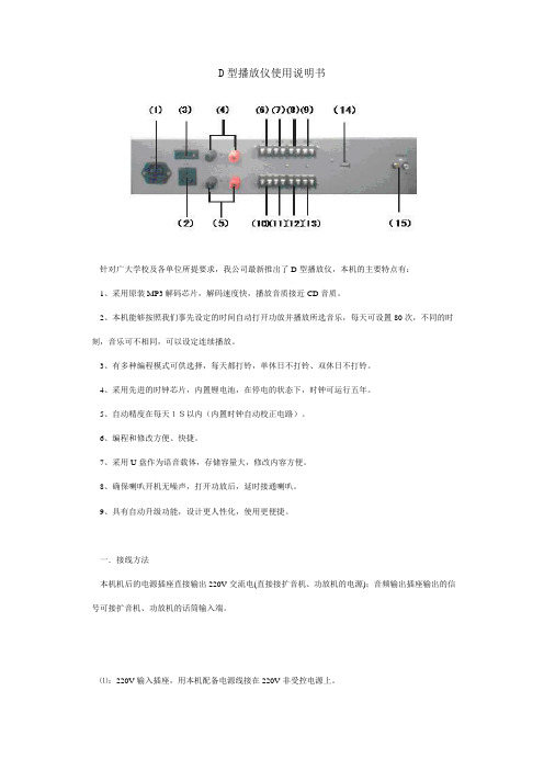
一.接线方法本机机后的电源插座直接输出220V交流电(直接接扩音机、功放机的电源);音频输出插座输出的信号可接扩音机、功放机的话筒输入端。
⑴:220V输入插座,用本机配备电源线接在220V非受控电源上。
⑵⑶:220V输出插座,接功放机/扩音机电源线。
⑷:输入Ⅰ端子,接功放机/扩音机输出。
⑸:输入Ⅱ端子,接功放机/扩音机输出。
⑹⑺⑻⑼:分区1、2、3、4端子,接负载。
(壁挂音箱、音柱、高音喇叭等)⑽⑾⑿⒀:分区5、6、7、8端子,接负载。
(壁挂音箱、音柱、高音喇叭等)⒁:USB接口,插U盘。
⒂:音频信号输出端口,用AV线连接到功放机/扩音机的线路/CD输入端。
二.快速应用2.1 快速编程编辑打铃点可采用两种方法:自动升级和手工编辑。
在此我们强烈推荐用户采用自动升级法,因为此方法直观、出错率低且容易使用。
2.1.1自动升级(推荐)1.在初次使用时,请将U盘中的编辑软件文件夹拷贝到电脑(请确保进行此操作,以防丢失编辑软件)。
2.对U盘进行格式化,以备PC端软件重构U盘分区信息(每次进行升级时,必须进行此操作,以确保PC端音乐信息与本机读到的升级文件信息同步,否则可能造成播放顺序混乱)。
无锡点创科技有限公司DCT-DO08型工业溶解氧仪操作手册说明书
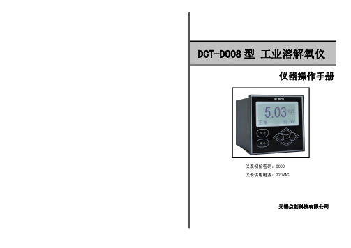
仪器操作手册仪表初始密码:0000仪表供电电源:220VAC无锡点创科技有限公司DCT-DO08型工业溶解氧仪简要操作说明该手册包含了仪表所有的操作细节,以下的简要操作说明用于帮助用户尽快学会操作使用仪表。
1、仪表安装:将仪表固定在仪表柜的面板上或仪表箱内,防止太阳直射或水淋,连接好电源电缆线,先不要通电(仪表正式使用前可通电热机1-2小时);2、电极安装:根据现场要求,将电极以沉入式(配沉入式护套管,请不要将电极电缆线直接浸泡在溶液中)、管道式(配不锈钢或PVC安装底座)、其它安装方式,可查看P3页参考;3、摘除电极头部的有机玻璃保护帽或橡胶保护帽,将电极安装好;4、将电极的接线端按所标号码与仪表后接线端标号一一对接;5、接通电源即可开始测量(使用前需进行一点空气斜率标定)。
重要安全信息请阅读和遵守下列各项:·当仪表选配使用220V AC供电电源时,仪表壳体后侧带有高电压,这可能导致危险出现。
在靠近仪表的这个区域前,请务必断开线路电源。
·接线或修理应有专业人员来完成,并且只对断电的仪表进行接线和修理。
·一旦仪表出现安全问题,立即将仪表断电,以防止任何无意操作。
例如,当下列情况时可能为非安全状态:1)仪表出现明显的损坏;2)仪表无法正常运行或提供指定的测量;3)仪表在温度超过50℃的环境中存放了较长时间。
溶氧仪十成套性名称数量1)DCT-DO08型电子单元1台2)溶氧电极及连接电缆线1支3)备品备件1套4)仪表安装支架2只5)电极安装附件(选配附件)1套6)仪器操作手册1本7)合格证1张注:使用前请检查购买仪表的成套性。
本公司其它系列分析仪表请登录我公司网站查询。
仪器使用小技巧:1、如何找回忘记的密码?答:进入售后服务菜单,当看到制造商联系方式时,“左”“右”键同时按,此时需输入密码“12345”,进入后将光标移动到最下面一排“密码”查看当前仪表密码。
2、如何修正温度误差值(此方法仅用于较小误差,如实际值相差较大则需检测仪表及电极是否正常工作)?答:进入售后服务菜单,当看到制造商联系方式时,“左”“右”键同时按,此时需输入密码“12345”,进入后将光标移动到“温度校准”,温度值偏小则直接输入误差值,温度值偏大则先输入负号再输入误差值。
在线DO电极的使用维护和保养

在线DO电极的使用维护和保养在线DO电极是一种用于测量水体溶解氧(Dissolved Oxygen)含量的传感器。
它主要由一个测量端和一个参比端组成。
测量端和参比端之间通过一个薄膜来隔离,薄膜能阻挡溶解氧通过,从而达到测量的目的。
在线DO电极的使用、维护和保养非常重要,可以帮助保持其准确性和延长使用寿命。
首先,使用在线DO电极前需要进行校准。
校准通常需要参考溶解氧标准溶液。
校准时,将电极插入标准溶液中,根据标准溶液的溶解氧浓度进行校准。
校准之后,确保电极会稳定工作。
在使用期间,避免将电极暴露于空气中,因为空气中的氧气会与电极反应,导致读数不准确。
此外,应尽量避免将电极暴露于高温、强酸或强碱的环境中,这些条件会损坏电极。
当未使用的时候,应将电极存放在有盖的容器中,防止污染和破损。
在线DO电极还需要定期清洗以去除附着在电极表面的污垢。
清洗时,首先将电极插入纯净水中淋洗,然后使用一种适当的清洗溶剂,如酸性清洗液,按照厂商提供的指导说明进行清洗。
清洗后,用纯净水彻底冲洗电极,确保清洗溶剂完全去除。
除了定期清洗,还需要定期校准在线DO电极。
通常,校准间隔为1-3个月,具体校准频率取决于具体的使用环境和频率。
校准前,先检查电极是否有损坏或腐蚀的迹象。
如果有任何问题,应及时更换电极。
校准时,按照校准标准溶液的浓度进行操作。
另外,在线DO电极的参比液需要定期更换。
参比液的作用是保持参比端与环境之间的稳定性,因此,当参比液发生变化时,可能会导致测量结果不准确。
建议至少每3个月更换一次参比液,具体更换频率根据实际使用情况而定。
总之,在线DO电极的使用、维护和保养非常重要。
定期清洗和校准能够保持电极的准确性和稳定性,延长其使用寿命。
另外,注意正确的操作和存放方法,避免暴露于不适宜的环境中,能够有效保护电极并保持其正常工作。
DO 电子液氧浇流仪操作手册说明书
(mg/L)
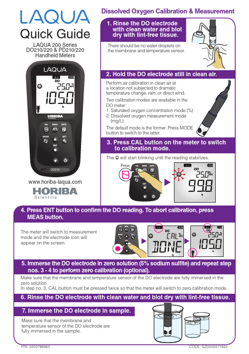
The default mode is the former. Press MODE button to switch to the latter.
Make sure that the membrane and temperature sensor of the DO electrode are fully immersed in the zero solution. In step no. 3, CAL button must be pressed twice so that the meter will switch to zero calibration mode.
Press
Press up or down buttons to scroll through settings
Press
Press ENT button to confirm settings
Press *Available in 220 models only
Quick Guide
LAQUA 200 Series DO210/220 & PD210/220
Handheld Meters
Dissolved Oxygen Calibration & Measurement
1. Rinse the DO electrode with clean water and blot dry with lint-free tissue.
在线监测仪操作规程
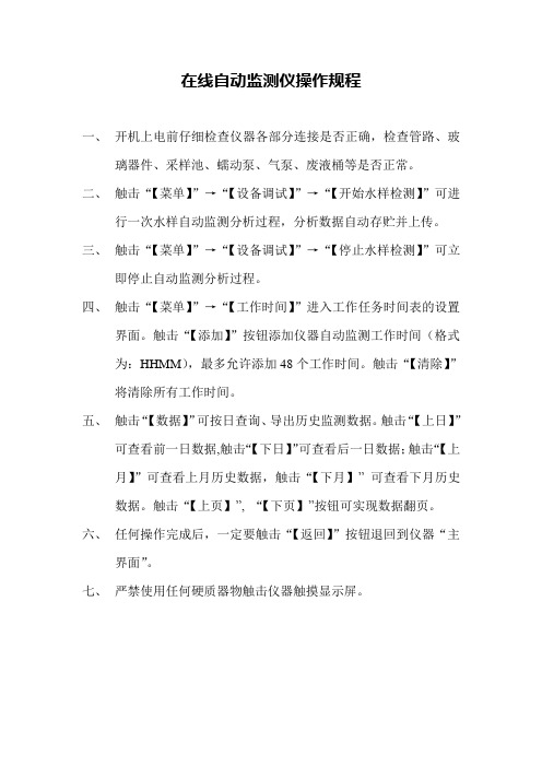
在线自动监测仪操作规程
一、开机上电前仔细检查仪器各部分连接是否正确,检查管路、玻
璃器件、采样池、蠕动泵、气泵、废液桶等是否正常。
二、触击“【菜单】”→“【设备调试】”→“【开始水样检测】”可进
行一次水样自动监测分析过程,分析数据自动存贮并上传。
三、触击“【菜单】”→“【设备调试】”→“【停止水样检测】”可立
即停止自动监测分析过程。
四、触击“【菜单】”→“【工作时间】”进入工作任务时间表的设置
界面。
触击“【添加】”按钮添加仪器自动监测工作时间(格式
为:HHMM),最多允许添加48个工作时间。
触击“【清除】”
将清除所有工作时间。
五、触击“【数据】”可按日查询、导出历史监测数据。
触击“【上日】”
可查看前一日数据,触击“【下日】”可查看后一日数据;触击“【上
月】”可查看上月历史数据,触击“【下月】”可查看下月历史
数据。
触击“【上页】”, “【下页】”按钮可实现数据翻页。
六、任何操作完成后,一定要触击“【返回】”按钮退回到仪器“主
界面”。
七、严禁使用任何硬质器物触击仪器触摸显示屏。
DO说明书
质量保证本产品提供自销售日起一年内的本机售后保证,但不包括不正当使用所造成之损坏,若需要维修或调整,请寄回,运费需自付,寄回时需确定包装良好以避免运送途中损坏,本公司将免费维修仪器内部的损坏。
(注:电极、标准液属于易耗品,不在保证范围内,本公司将保证电极交付使用时的品质。
)使用说明书9.电极使用保养本公司研发的溶氧电极应用极谱式原理,采用高性能透氧膜, 响应时间短,测量准确,性能稳定,维护方便。
溶氧电极电维护请注意以下几点:(1) 电极应定期清洗,拆装及清洗电极时不能弄破透氧膜,不能用滤纸擦电极上的透氧膜,以免损坏透氧膜。
(2) 必须保持电缆连接头清洁,不能受潮或进水。
(3) 仪器显示值与实际值相差很大或不能测定低含量的氧时,可能氧电极内的电解液干涸,需重新灌注入电解液,一般情况下更换或添加电解液的维护工作每6个月进行一次;渗透膜破裂时需要更换备用膜头。
每次更换或添加电解液或更换备用膜头后,电极需重新极化和标定。
具体步骤如下:倒放电极,拧开电极下部的黑色部分电极护罩,取下膜头,倒掉空腔内的旧液,灌入原配的电解液,不要太满,让多余的电解液排掉。
旋紧并保证膜能贴紧电极芯的头部即可。
更换好电解液后,应重新进行极化和标定。
(4)电极极化:电极连接到仪器上后,连续通电0.5小时以上,即为极化,电极极化后才能进行标定。
(5)当现场较长时间断水或仪表较长时间不使用时,应及时取出电极,并清洗干净套上保护帽。
(6)如果电极失效需更换电极。
-15-7.温补设置仪表为自动温度补偿方式。
没有温补时,显示为25.0℃。
8.空气中溶氧度对照表目录注意事项1.产品配置……………………………………………………‥1 2.产品简介……………………………………………………‥2 3.技术指标……………………………………………………‥3 4.仪表安装……………………………………………………‥44.1、主机安装 (4)4.2、电极安装 (4)5.仪表面板及接线说明 (6)6.仪表功能设置 (8)6.1.主菜单 (8)6.2.DO标定 (8)6.3.报警设置 (10)6.4.通讯及出厂设置 (11)6.5.电流输出设置 (12)6.6.记事本 (13)7.温度补偿 (14)8.空气中溶氧度对照表 (14)9.电极使用保养 (15)注意事项●使用时请遵守本说明书之操作规程及注意事项。
DO说明书(OEM版本)
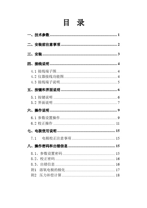
目录一、技术参数 (1)二、安装前注意事项 (2)三、安装 (3)四、接线说明 (4)4.1接线端子图 (4)4.2仪器接线功能图 (4)4.3接线端子说明 (5)五、按键和界面说明 (6)5.1按键说明 (6)5.2界面说明 (7)六、操作说明 (9)6.1参数设置操作 (9)6.2校正操作 (11)七、电极使用说明 (15)7.1电极校正注意事项 (15)八、操作密码和出错信息 (15)8.1、参数设置密码 (15)8.2、校正密码 (16)8.3、出错信息 (16)附1溶氧电极的极化 (17)附2压力补偿计算 (18)一、技术参数1二、安装前注意事项1、请选择通风良好的位置安装变送器(以下简称仪器),并避免仪器直接受到阳光照射。
2、安装前请阅读本说明书,以免接线不正确导致仪器损坏。
3、在所有接线未完成前,请勿给仪器上电,以免发生危险。
4、DO电极信号传输须采用专用电极电缆,不能随便用一般电缆代替,否则将产生错误的测量结果。
5、使用220VAC的电源时,请避免使用三相电源,以免造成电源突波干扰。
(若有电源突波干扰现象发生,可将仪器用的电源与动力装置电源分开,即仪器采用单独电源,或在所有动力装置的电源端接突波吸收器来消除突波,如加药机、搅拌机等)。
6、仪器内部的继电器为小电流继电器,若要控制较大动力的附属装置时,请外接电流容量较大的继电器,以确保仪器的安全。
7、下图为仪器和动力装置的接线示意图。
图2-1 仪器和动力装置接线示意图23三、安装1、在配电箱面板上开好110+1mm×110+1mm 的仪器安装方孔。
2、仪器从配电箱的面板直接放入,将仪器附带的的固定架卡入仪器两侧的固定孔,用一字型螺丝刀拧紧固定螺丝。
安装示意图如下:主视示意图侧视示意图固定示意图开孔尺寸图3-1 仪器尺寸和安装示意图4四、接线说明4.1 接线端子图14220VAC234~20mA5图4-1 仪器接线端子图【注:如果订货时没有报警、清洗功能,Hi 、Lo 和WASH 端子无效】 4.2 仪器接线功能图4-20mA -220VAC图4-2 仪器接线功能图4.3 接线端子说明注:通常情况下,接地线“E”不接。
Aquapro多通道在线仪表说明书

Thermo Scientific Thermo Scientific AquaPro AquaPro™™ 多通道在线测量仪操作手册目录1.介绍 (3)1.1基本资料 (3)1.2用途 (3)1.3安全指示 (3)1.4停止服务和正确的处理方法 (4)2.产品描述 (5)2.1概括 (5)2.2AquaPro测量仪平台传感器兼容性 (5)2.3AquaPro测量仪产品配置选型表 (7)2.4AquaPro测量仪的安装 (8)2.4.1安装 (8)2.5电源、继电器、电流输出接线 (13)2.5.1接线孔的准备 (13)2.5.2接线 (13)2.5.3功能卡的类型 (15)2.6传感器接线 (15)2.6.1Analog模拟量传感器——pH、ORP、臭氧、溶解氧(极谱式) (15)2.6.2复合pH传感器接线 (15)2.6.3差分pH传感器接线 (16)2.6.4差分ORP传感器接线 (16)2.6.5AnalogPlus臭氧传感器接线 (17)2.6.6AnalogPlus溶解氧传感器接线 (17)2.6.7模拟量传感器——二环电导率/电阻率传感器和环形电导率传感器 (17)2.6.8AnalogPlus环形电导率传感器接线 (18)2.6.9AnalogPlus二环电导率传感器接线 (18)2.6.10DataStick传感器接线 (19)2.6.11DO功能卡只能与RDO Pro探头连接 (19)2.7继电器接线 (20)2.7.1继电器功能卡 (20)2.8主机通讯接线 (20)2.8.1主机数字通讯功能卡 (20)2.9现场更换/添加传感器功能卡和其它功能卡 (21)2.10测量屏幕显示 (22)3.菜单设置 (24)4.校正菜单 (27)4.1pH校正 (27)4.1.11点pH校正 (28)4.1.22点pH校正 (28)4.2ORP(氧化还原电位)校正 (28)4.2.1 1点ORP校正 (28)4.3接触式电导率 (28)4.3.11点接触式电导率校正 (28)4.4环形电导率 (28)4.5AnaLogPlus DO或DataStick DO校正 (29)4.5.11点DO校正 (29)4.6RDO Pro荧光法溶解氧 (29)4.6.11点RDO校正 (29)4.7DataSticks (30)5.诊断菜单 (31)5.1系统信息 (31)5.2校正记录 (31)5.3事件日志 (31)5.4模拟量输出状态 (31)5.5继电器状态 (31)6.设置菜单 (32)7.PID功能 (34)8.继电器 (36)9.主机通讯 (37)10.故障排除 (38)11.订货信息 (39)12.技术规格 (40)12.1传感器测量范围 (40)12.2功能特点 (40)12.3安装方式 (41)12.4操作界面 (41)12.5环境要求 (41)12.6可更换模块 (41)12.74-20mA电流输出 (41)12.8继电器 (42)12.9通讯协议 (42)12.10电源 (42)1. 介绍1.1 基本资料感谢您选择Thermo Scientific AquaPro 系列多通道在线测量仪。
DO4100e简要操作说明
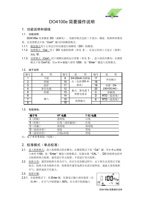
DO4100e 简要操作说明1. 功能说明和接线1.1. 功能说明DO4100e 用来测量DO (溶解氧),其操作模式包括三个部分:测量、校准和参数设置。
在设置模式中按“Conf ”键可回到测量模式。
1.1.1. 测量模式用于正常运行时仪器进行溶解氧(DO )的测量。
1.1.2. 校准模式(Cal )用于DO 电极的校准(参见2)。
在显示屏的上方显示(校准)图标 。
1.1.3. 设置模式(Conf )用于调整仪器的运行参数(参见3)。
进入的的步骤为:在测量模式下按Conf 键,用 和 键输入密码1200,按“Enter ”键进入设置模式。
1.2. 端子说明 编号说 明编号说 明 编号说 明 1 不接 9 172 阴极 10 18冲洗触点3 防护 11 0/4-20mA 两路输出(包括DO 和温度) 194 参比电极 12 20电源(24-230VDC/AC ) 5 阳极 13 C屏蔽线6 14触点,继电器1和继电器2D RTD (温度线)7 15 ERTD (温度线)8 输入 16 报警触点1.3. 电缆接线:端子号 VP 电缆 T-82电缆 2(阴极) 透明线 白线 5(阳极) 红线(或屏蔽线) 红线 C (屏蔽) 黄绿线 黄绿线 D (温度补偿) 绿线 黑线 E (温度补偿) 白线+灰线 黑线注:端子4和5跨接(短路)。
2. 校准模式(单点校准)2.1. 进入校准模式:进入校准模式的步骤为:在测量模式下按“Cal ”键,用 和 键输入密码1100,按“Enter ”键进入校准模式,仪器出现“CAL ”。
DO 的校准包括单点校准和两点校准,通常进行单点校准,不需进行零点校准。
2.2. 校准介质:通常的校准介质为空气。
但在生化发酵过程中,由于探头在消毒后不能取出,校准介质为饱和介质,校准条件通常选择在实消后接种前,通最大量的饱和空气,搅拌速度开至最大。
2.3. 校准步骤:2.3.1. 在校准模式下,按Enter 键,仪器显示输入相对湿度(出现rH ),在空气中校准输入50%,在介质中校准输入100%。
DO计使用说明
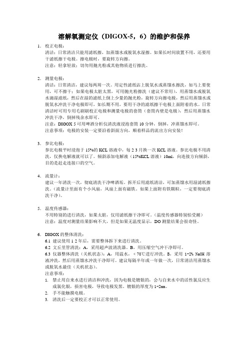
溶解氧测定仪(DIGOX-5,6)的维护和保养1.校正电极:清洁:日常清洁只能用滤纸擦,加蒸馏水或脱氧水湿擦。
如果长时间放置不用,还要用干滤纸擦干电极。
擦电极时,要旋转方向擦。
注意:轻拿轻放;切勿用抛光粉或其他物质进行擦洗。
2.测量电极:清洁:日常清洁,建议每两周一次。
用定性滤纸沾上脱氧水或蒸馏水擦洗,如马上要使用,可不擦干;如果电极太脏太黑,可用抛光粉擦洗(建议不常用),用蒸馏水或脱氧水滴湿滤纸,然后在湿的滤纸上倒上少量的抛光粉,旋转方向擦电极,然后用蒸馏水或脱氧水冲洗干净电极即可,如长期不用,要用干净的滤纸擦干电极上面附着的水。
日常清洁时可用专用毛刷刷校正电极和测量电极的套筒(套筒内壁是电极),然后用蒸馏水冲洗干净,倒掉残余水即可。
注意:DIGOX-5可用啤酒分析仪清洗液浸泡套筒10分钟,倒掉,冲蒸馏水即可。
注意事项:电极的安装一定要沿着斜面方向,顺着样品的流出方向安装!3.参比电极:参比电极平时浸泡于15%的KCL溶液中,每2-3月换一次KCL溶液。
参比电极不用清洗,仅换电解液就可以了。
倾斜添加电解液(15%KCL溶液)10ml,向连接方向倾斜,目的是赶走连接口的空气。
4.流量计:建议一年清洗一次,彻底清洗干净啤酒垢。
拆开后用滤纸清洁,可加蒸馏水用湿滤纸擦洗。
(流量计里面有个小风扇,风扇上面有磁铁。
如果上面附有铁颗粒,一定要彻底清洗干净)。
5.温度传感器:不用特别的进行清洗,如果太脏,仅用滤纸擦干净即可。
(温度传感器特别怕受潮)注意:温度对测量结果影响不大,但是如果无温度显示,DO测量结果会很奇怪。
6.DIGOX的整体清洗:6.1 建议使用1-2年后,需要整体拆下来进行清洗。
6.2 文丘里管清洗:A,采用超声波清洗器。
B,用压缩空气冲干净即可。
6.3 仪器整体清洗(关机状态):A,用温水,﹤70℃进行冲洗。
B,采用1-2% NaOH溶液冲洗,然后用蒸馏水冲洗干净即可。
建议每隔半年或一年做一次,日常清洁用蒸馏水或脱氧水最佳(关机状态)。
do200操作手册 使用说明书ysi do200

存在大气泡都会导致读数漂移。如果出现不稳定读数或膜受损,请更换盖膜和溶解氧探头溶液(也称 为“溶解氧探头电解液”、氯化钾或 KCL 溶液)。盖膜的平均更换周期为 4-8 周;如果保持洁净,可使 用更长时间。若在恶劣环境(如废水)中使用,可能每 2-4 周就需要换膜。如果盖膜被耗氧或释氧的 生物(如细菌、藻类等)所覆盖,读数可能会不稳定。 2. 二氧化硫、一氧化氮、一氧化二氮会影响读数,传感器会误把此类气体当作氧气。 3. 避开可能损伤探头材料的物质,如浓酸、强碱和强力溶剂。探头材料包括不锈钢、环氧树脂和 ABS 塑 料。 4. 保持探头的黄金阴极洁净及质感(正确维护后有纹理和光泽)。探头若因接触到某些气体变得暗淡或镀 上了银(因长期使用不牢固或有皱褶的膜),请按照“探头维护”的指示清洁探头。 5. 为防止盖膜和电解液脱水,请将探头保存在盛有湿润海绵的校准杯中。
【实用文档】DO仪的使用
1.0目的
正确使用DO仪检测溶解氧。
2.0适用范围
太古饮品 ( 东莞 )有限公司污水处理厂
3.0职责
污水处理员负责此程序的执行。
4.0定义
无
5.0程序
5.1.先按ON/OFF键打开仪器,显示器上出现“POL”自动极化开始,300秒后,极化接束。
5.2.100%校正
5.2.1.去掉电极保护帽,用蒸馏水冲洗电极,擦干电极上的水滴
5.2.2.按住CAL键,再按一下ON键后松开CAL键,这时显示器上出现“CAL”和
“POL”,并持续300秒。
5.2.3.当出现“ENT”时,按+键,这时显示“SET”,等待20~30秒,按下CAL键,此
时将显示“100%”,并转化到测试状态。
5.3.检测
5.3.1.将电极插入水样,轻轻摇动水样,等显示值趋于稳定时按下HOLD键,这时显示器
上的读数就是测定数值。
5.3.2.按+/_键,所测数值在浓度(MG/L)、饱和度、压力、温度之间转换。
6.0参考文献
6.1.本文件支持纲要文件R-QA-015 废水处理质量纲要
6.2.相关SOP文件:SOP-QA-WWT-001 废水处理的运行与监控
SOP-QA-WWT-002 单级好氧处理的运行与监控7.0附件/结果
记录检测结果于表:WWTP分析记录表 FM-WWT-001~002 存档于品控部两年。
自动滴定仪操作手册
METTLER TOLEDO TitratorsDirect Measurementwith Ion Selective ElectrodesApplication brochure 6EditorialDear ReaderUsing ion selective electrodes (ISE) to determine ion contents, today’s analyst has a simple, reliable and versatile method at hand.It pleases us to present these applications to you. Using lots of examples, they will show you how you can use the METTLER TOLEDO DX ion selective electrode series, together with titrators DL67 / DL70ES / DL77, to solve many of your analysis tasks. This builds up on the many possibilities for adapting methods offered by titrators DL67 / DL70ES / DL77. This, of course, together with the clear user guidance offered by alphanumeric and grafic displays in plain language.The applications examples are mostly taken from the area of foods and beverages. However, they also represent samples from other areas such as chemicals, cosmetics and environmental protection. Matrix effects and the influence of interfering ions (cross sensitivity) are explained. Hints for pre-venting or reducing these are given wherever possible. Also included is a list of references which we mention explicitly in this context.A load of practical tips and hints are included with the individual measurements. These are summa-rized in the chapter on trouble-shooting.A further benefit of the use of ion selective electrodes is the minimal use of chemicals and the avoid-ance of environmentally damaging wastes, ecologically as well as economically an important consid-eration.Unless the sample must be buffered, the method is also non-destructive.The analyses were mostly performed with perserverance and success in our lab by Anke Stock, as a part of the work required for her to attain her chemical engineering Masters degree.Albert Aichert, Market Support AnaChem, included numerous additions and edited this brochure. Many thanks to both authors.A further brochure will describe the addition procedures also used in measurements with ion selective electrodes.We are convinced that the inclined reader, thanks to the broad scope of information, will soon feel at ease using ion selective electrodes. The new tools should help him/her readily solve new problems. We wish you lots of luck using ion selective electrodes together with our titrators .Georg Reutemann Rolf M. RohnerManager Market Support Marketing ManagerPage 2 / 68 METTLER TOLEDO DL5x and DL7x Titrators Direct Measurement with Ion Selective ElectrodesContents1.Fluoride Selective Electrode (4)M101Calibrating the Fluoride Electrode (6)M102Fluoride Determination with Fluoride Ion Selective Electrode (8)M071Fluoride Determination in Water (12)2.Chloride Selective Electrode (14)M103Calibrating the Chloride Electrode (16)M104Chloride Determination with Ion Selective Chloride Electrode (18)M105Chloride Determination in Canned Vegetables (22)3.Nitrate Selective Electrode (24)M106Calibrating the Nitrate Electrode (26)M107Automatic Three-point Calibration of the Nitrate Electrode (28)M108Nitrate Determination with Ion Selective Electrode (30)M109Nitrate Determination in Reference Samples (34)4.Potassium Selective Electrode (36)M110Calibration of the Potassium Electrode (38)M111Potassium Determination with Ion Selective Electrode (40)5.Sodium Selective Electrode (44)M112Calibration of the Sodium Electrode (46)M113Sodium Determination with Ion Selective Electrode (48)6.Trouble-shooting (52)7.Summary of the Ion Selective Electrodes and Reagents Used (54)8.Literature (56)9.Sample index (63)Direct Measurement with Ion Selective Electrodes METTLER TOLEDO DL5x and DL7x Titrators Page 3 / 681.Fluoride Selective ElectrodeTheory The fluoride electrode is a solid state membrane electrode. The active electrode phase is a nearly water insoluble lanthanide fluoride monocrystal which is indirect contact with the measurement solution. The potential difference derivedfrom the equationLaF3⇔ La+3 + 3 F- is conducted by the electrolyte and a noble metal wire.The theoretical detection limit of the fluoride electrode is determined by the lowsolubility of the LaF3 crystal (10-26). Using TISAB to adjust the pH value and theionic strength, linear calibration curves of 0.1 – 10-6 mol/L are attained; thedetection limit lies slightly higher than 10-7mol/L. The slope, theoreticallycalculated from the Nernst equation to be 59.16 mV/pF at 25°C, usually lies at58-59mV/pF in practice.ElectrodesBridging electrolyte As bridging electrolyte for the reference electrode, a 1 mol/L KNO3 solution isused.Conditioning For the determination of concentrations under 1 mg/L, the electrode should be conditioned in deionized water for approx. 30 minutes.Storage Store electrodes dry or in a dilute fluoride solution. The electrolyte should not be submerged for long in solutions containing TISAB, as the crystal surface isdamaged by complexing agents.Handling The lanthanide fluoride crystal is sensitive to mechanical impact. Cracks and scratches render the electrode useless. Avoid fat deposits on the crystal; do nottouch with bare fingers.Contamination A sluggish or no response indicates that the sensor is contaminated. Deposits on the crystal can be removed carefully by wiping with a soft tissue. Afterwards itis advantageous to condition for several minuts in a dilute fluoride solution.Repolish non-regenerable modules with an aqeous slurry of aluminum oxide orwith toothpaste.ReagentsTISAB solutions:(Total Ionic Strength Adjustment Buffer)METTLER TOLEDO TISAB 3Art. No. 51 340 064(mix 1:10 with sample)MERCK TISAB I Art. No. 153668 (1:1 mix with sample), contains NaClTISAB III Art. No. 116770 (1:10 mix with sample), contains NH4ClSelf made In 700mL deion. water are dissolved 58g NaCl p.a. and 5g CDTA (1,2-diaminocyclohexane-N,N,N’,N’-tetraacetate, Titriplex IV from MERCK, No.108424, or Complexon IV p.a.) by adding 5mol/L NaOH solution.Add 57mL glacial acetic acid p.a and adjust to pH 5.5 using sodium hydrox-ide c(NaOH) = 5 mol/L at 20°C. Adjust volume to 1000 mL using deion wa-ter. The pH value of this solution should be 5.3 (20°C).Page 4 / 68 METTLER TOLEDO DL5x and DL7x Titrators Direct Measurement with Ion Selective ElectrodesF- stock solution:Fluoride standard solution (potassium fluoride in water) 1.000 g ± 0.002g F-MERCK Art. No. 109869Fill to 1000 mL with deion. water and decant to plastic bottle.1 mL = 1mg fluoride.Appropriate standard solutions are made from this stock.RemarkspH Value At pH values under pH=5, HF and HF2- are formed. Both are not detected by the fluoride electrode. At pH values over pH=8, La(OH)3 is formed and the electroderesponds increasingly to OH- ions.Interfering ions Metal ions such as Al3+, Fe3+, Si4+, Ca2+, Fe2+, and other polyvalent ions form complexes with fluoride, some of which are stable. The fluoride bound in thismanner can be released for determination by adding Complexon IV (found inTISAB solution) for preferential complexing.Ionic strength The total activity of calibration and measurement solutions must be constant. By adding a constant amount of TISAB solution, the pH is buffered sufficiently andthe solution is adjusted to a constant ionic strength.Samples Samples and standard solutions should be stored only in PE or PP bottles with fluoride-saturated walls.Glass utensils Any glass utensils used should first be rinsed with sodium hydroxide (0.01mol/ L) to block glass against fluoride ions.Deion. water The deion. water used to make solutions should be made basic using sodium hydroxide. This prevents fluoride loss.Application and UseApplication The fluoride electrode is used for fluoride determination in air, water, beverages, foods, dental hygiene articles, organic compounds, vegetation, soil and rocksamples.Use Direct measurement with an ion selective electrode is the method of choice for fluoride determination. The high selectivity and large concentration range makethis method universally applicable .Alternatives Ion chromatography.Potentiometric titration using a fluoride electrode and lanthanide nitrate astitrant at pH=6.3 F- + La(NO3)3 = LaF3 + 3 NO3-This method is applicable only for higher fluoride concentrations (more than20 mg/L). It is rarely used in practice.Advantages- wide application range (1000 - 0.01 mg/L)- the determination is fast and simple- no heavy metal wastes- small investment (compared to ion chromatography)Disadvantages noneDirect Measurement with Ion Selective Electrodes METTLER TOLEDO DL5x and DL7x Titrators Page 5 / 68METTLER TOLEDOPage 6 / 68 METTLER TOLEDO DL5x and DL7x Titrators Direct Measurement with Ion Selective ElectrodesM101Calibrating the Fluoride ElectrodeSample:50 mL fluoride solution 10-1 g/L, 10-2 g/L, 10-4 g/L Substance:FluorideM = 18.998 g/mol , z = 1Preparation: 5 mL TISAB III MERCK Titrant:--Standard:--Instruments:METTLER TOLEDO DL70ESHP Deskjet 500 Printer MT AT261 Balance Method:F007Accessories:Titration beaker ME-101974DT120 (temp. sensor Pt100)Indication:DX219 Fluoride ISEDX200 Reference electrode (bridge electrolyte: 1 M KNO 3)Results:METTLER DL70ES Titrator V3.0 Mettler-Toledo AGAA01 Market Support Laboratory Method F007 Calibration F --sensor 09-Nov-1993 17:46 User aaMeasured 10-Nov-1993 10:27 RESULTSNo ID1 ID2 Sample amount and results1/1 10-4 g/L 50.0 mL pH,pM,pX 4.000 R1 = 158.267 mV Potential 1/2 10-2 g/L 50.0 mL pH,pM,pX 2.000 R1 = 42.349 mV Potential 1/3 10-1 g/L 50.0 mL pH,pM,pX 1.000 R1 = -15.540 mV PotentialCALIBRATIONSensor F --sensor Buffer type pH,pM,pXZero point 1.269 pX0 Slope 57.94 mV/pX Calibration temperature 21.7 °CDirect Measurement with Ion Selective ElectrodesMETTLER TOLEDO DL5x and DL7x Titrators Page 7 / 68MethodRemarks1)Calibration and measurement solutions shouldalways be at the same temperature.2)All measurements should be performed usingthe same stirring conditions. This means the same speed, stirrer type, distance to electrode etc.3)The calibration parameters are automaticallystored in the installation data by the titrator.They are then referred to the sensor indicated in the method and are applicable only for this sensor.4)Up to 8 standard solutions can be used for thecalibration. If only one standard is used, the titrator will correct only the zero point.5)Rinse electrode with deion. water after eachmeasurement and remove adhering water drops with a soft paper tissue.6)It is necessary to stir for approx. 5 minutes eachmeasurement to attain a stable measured value.7) For a three-point calibration with automaticproduction of the standard solutions, see the nitrate electrode.Disposal--Other titratorsDL50 Graphix, DL53/55/58, DL77 titrators.Method F007 Calibration F --sensor Version 09-Nov-1993 17:46TitleMethod ID . . . . . . . . . . . . . F007Title . . . . . . . . . . . . . Calibration F --sensor Date/time . . . . . . . . . . . . . 09-Nov-1993 17:46SampleNumber samples . . . . . . . . . . 3Titration stand . . . . . . . . . . Stand 1Entry type . . . . . . . . . . . . . Fixed volume U Volume [mL] . . . . . . . . . . . 50.0 ID1 . . . . . . . . . . . . . . . .Molar mass M . . . . . . . . . . . . 0.0 Equivalent number z . . . . . . . . 1Temperature sensor . . . . . . . . . TEMP A StirSpeed [%] . . . . . . . . . . . . . 50 Time [s] . . . . . . . . . . . . . . 300MeasureSensor . . . . . . . . . . . . . . F --sensor Unit of meas . . . . . . . . . . . . mV ∆E [mV] . . . . . . . . . . . . . . 0.5 ∆t [s] . . . . . . . . . . . . . . 2.0 t(min) mode . . . . . . . . . . . . Fix t(min) [s] . . . . . . . . . . . 10.0 t(max) [s] . . . . . . . . . . . . . 30.0CalculationResult name . . . . . . . . . . . . Potential Formula . . . . . . . . . . . . . . R=E Constant . . . . . . . . . . . . . . Result unit . . . . . . . . . . . . mV Decimal places . . . . . . . . . . . 3CalibrationSensor . . . . . . . . . . . . . . . F --sensor Buffer type . . . . . . . . . . . . pH,pM,pX First buffer . . . . . . . . . . 4.0 Second buffer . . . . . . . . . . 2.0 Third buffer . . . . . . . . . . 1.0 Fourth buffer . . . . . . . . . . 0.0 Fifth buffer . . . . . . . . . . 0.0 Sixth buffer . . . . . . . . . . 0.0 Seventh buffer . . . . . . . . . 0.0 Eighth buffer . . . . . . . . . . 0.0 Ri (i=index) . . . . . . . . . . . . R1 Minimal slope . . . . . . . . . . . 50.0 Maximal slope . . . . . . . . . . . 60.0RecordOutput unit . . . . . . . . . . . . Printer All results . . . . . . . . . . . . YesAuthor: Albert AichertTypical calibration curve of a fluoride selective electrode with TISAB solutionMETTLER TOLEDOPage 8 / 68 METTLER TOLEDO DL5x and DL7x TitratorsDirect Measurement with Ion Selective ElectrodesM102Fluoride Determination with Fluoride Ion Selective ElectrodeSample:50 mL sample solution with 1000 to 0.01 mg/L fluoride Substance:FluorideM = 18.998 g/mol , z = 1Preparation: 5 mL TISAB III MERCK Titrant:-Standard:-Instruments:METTLER TOLEDO DL70ESPrinter (HP Desk Jet 500)Method:F00A, F00BAccessories:Titration beaker ME-101974DT120 (temp. sensor Pt100)Indication:DX219 Fluoride ISEDX200 Reference electrode (bridge electrolyte: 1 M KNO 3)Repeatability and Recovery Rate 1.For these measurements, aqueous fluoride solutions from the fluoride standard solution (potas-sium fluoride in water) 1.000g ± 0.002g fluoride, MERCK Art. No. 109869, were used.2.The fluoride electrode was recalibrated at least once a day using 10mg/L and 0.1mg/L standard solutions (sometimes necessary after 3-4 series).3.Preparation: Add 5mL TISAB III to 50mL sample solution and measure.ConcentrationRecoverysrel from several series (n=6)mg / L%Method A Method B 1000100 - 105 %0.09 - 0.20 %0.15 - 0.26 %100100 - 103 %0.06 - 0.20 %0.11 - 0.20 %1099 - 101 %0.13 - 0.26 %0.18 - 0.24 %198 - 100 %0.15 - 0.31 %0.19 - 0.36 %0.199 - 102 %0.15 - 0.45 %0.27 - 0.51 %0.0597 - 101 %0.10 - 0.84 %0.12 - 0.91 %0.01155 - 181 %0.38 - 4.6 %0.42 - 2.47 %Result:Method (A) allows to obtain a a better repeatability, expressed as relative standard deviation srel.However, the adjstment time prior to the measurement is crucial for good repeatability. At high concentrations (1000 - 0.1mg/L) the stirring time is 5 minutes. At low concentrations, longer times are necessary: for 0.05g/L approx. 10minutes, and for 0.01g/L approx. 20minutes.The concentration 0.01mg/L is not in the linear range (see calibration curve page 7). The range of concentrations for fluoride sensitive electrodes was therefore limited from 100 to 0.05mg/L.Direct Measurement with Ion Selective ElectrodesMETTLER TOLEDO DL5x and DL7x Titrators Page 9 / 68Method AOther titratorsDL53+, DL55+, DL58, DL77 titrators.Author: Albert AichertMethod F00A F --contentVersion 10-Sep-1993 16:05TitleMethod ID . . . . . . . . . . . . . F00ATitle . . . . . . . . . . . . . F --contentDate/time . . . . . . . . . . . . . 10-Sep-1993 16:05SampleNumber samples . . . . . . . . . . 6Titration stand . . . . . . . . . . Stand 1Entry type . . . . . . . . . . . . . Fixed volume U Volume [mL] . . . . . . . . . . . 50.0 ID1 . . . . . . . . . . . . . . . .Molar mass M . . . . . . . . . . . . 0.0 Equivalent number z . . . . . . . . 1Temperature sensor . . . . . . . . . TEMP A StirSpeed [%] . . . . . . . . . . . . . 50 Time [s] . . . . . . . . . . . . . . 300MeasureSensor . . . . . . . . . . . . . . F --sensorUnit of meas . . . . . . . . . . . . As installed ∆E [mV] . . . . . . . . . . . . . . 0.2 ∆t [s] . . . . . . . . . . . . . . 5.0 t(min) mode . . . . . . . . . . . . Fix t(min) [s] . . . . . . . . . . . 10.0 t(max) [s] . . . . . . . . . . . . . 90.0MeasureSensor . . . . . . . . . . . . . . F --sensor Unit of meas . . . . . . . . . . . . mV ∆E [mV] . . . . . . . . . . . . . . 0.2 ∆t [s] . . . . . . . . . . . . . . 2.0 t(min) mode . . . . . . . . . . . . Fix t(min) [s] . . . . . . . . . . . 1.0 t(max) [s] . . . . . . . . . . . . . 2.0MeasureSensor . . . . . . . . . . . . . . F --sensor Unit of meas . . . . . . . . . . . . mV ∆E [mV] . . . . . . . . . . . . . . 0.2 ∆t [s] . . . . . . . . . . . . . . 2.0 t(min) mode . . . . . . . . . . . . Fix t(min) [s] . . . . . . . . . . . 1.0 t(max) [s] . . . . . . . . . . . . . 2.0MeasureSensor . . . . . . . . . . . . . . F --sensor Unit of meas . . . . . . . . . . . . mV ∆E [mV] . . . . . . . . . . . . . . 0.2 ∆t [s] . . . . . . . . . . . . . . 2.0 t(min) mode . . . . . . . . . . . . Fix t(min) [s] . . . . . . . . . . . 1.0 t(max) [s] . . . . . . . . . . . . . 2.0MeasureSensor . . . . . . . . . . . . . . F --sensor Unit of meas . . . . . . . . . . . . mV ∆E [mV] . . . . . . . . . . . . . . 0.2 ∆t [s] . . . . . . . . . . . . . . 2.0 t(min) mode . . . . . . . . . . . . Fix t(min) [s] . . . . . . . . . . . 1.0 t(max) [s] . . . . . . . . . . . . . 2.0MeasureSensor . . . . . . . . . . . . . . F --sensor Unit of meas . . . . . . . . . . . . mV ∆E [mV] . . . . . . . . . . . . . . 0.2 ∆t [s] . . . . . . . . . . . . . . 2.0 t(min) mode . . . . . . . . . . . . Fix t(min) [s] . . . . . . . . . . . 1.0 t(max) [s] . . . . . . . . . . . . . 2.0CalculationResult name . . . . . . . . . . . .Formula . . . . . . . . . . . . . . R1=E[1] Constant . . . . . . . . . . . . . .Result unit . . . . . . . . . . . . p(F -) Decimal places . . . . . . . . . . . 4CalculationResult name . . . . . . . . . . . . F --singleFormula . . . . . . . . . . . . . . R2=pw(-E[1])*1000 Constant . . . . . . . . . . . . . .Result unit . . . . . . . . . . . . mg/L Decimal places . . . . . . . . . . . 4CalculationResult name . . . . . . . . . . . .Formula . . . . . . . . . . . . . . R3=(C3+E[5]+E[6])/6 Constant . . . . . . . . . . . . . . C3=E[1]+E[2]+E[3]+E[4] Result unit . . . . . . . . . . . . Decimal places . . . . . . . . . . . 3CalculationResult name . . . . . . . . . . . . F --x of 6Formula . . . . . . . . . . . . . . R4=pw(-R3)*1000 Constant . . . . . . . . . . . . . .Result unit . . . . . . . . . . . . mg/L Decimal places . . . . . . . . . . . 4StatisticsRi (i=index) . . . . . . . . . . . . R2 Standard deviation s . . . . . . . . Yes Rel. standard deviation srel . . . . Yes Outlier test . . . . . . . . . . . . Yes StatisticsRi (i=index) . . . . . . . . . . . . R4 Standard deviation s . . . . . . . . Yes Rel. standard deviation srel . . . . Yes Outlier test . . . . . . . . . . . . Yes RecordOutput unit . . . . . . . . . . . . Printer All results . . . . . . . . . . . . YesMethod BRemarksMethod A1)Stirring during 5 minutes.2)Acquisition of six values (six Measure-func-tions) at an interval of 1-2 s.3)The fluoride concentration is calculated from the mean of these six values.Method B1)Stirring during 5 minutes.2)Acquisition of one value.3)If the sample is diluted for the measurement,the dilution factor can be entered as a correc-tion factor (f) for each sample. This will be used in the calculation.Method F00B F --contentVersion 16-Sep-1993 10:21TitleMethod ID . . . . . . . . . . . . . F00BTitle . . . . . . . . . . . . . F --contentDate/time . . . . . . . . . . . . . 16-Sep-1993 10:21SampleNumber samples . . . . . . . . . . 6Titration stand . . . . . . . . . . Stand 1Entry type . . . . . . . . . . . . . Fixed volume U Volume [mL] . . . . . . . . . . . 50.0 ID1 . . . . . . . . . . . . . . . . F - Molar mass M . . . . . . . . . . . . 18.99840 Equivalent number z . . . . . . . . 1Temperature sensor . . . . . . . . . TEMP A StirSpeed [%] . . . . . . . . . . . . . 50 Time [s] . . . . . . . . . . . . . . 300MeasureSensor . . . . . . . . . . . . . . F --sensorUnit of meas . . . . . . . . . . . . As installed ∆E [mV] . . . . . . . . . . . . . . 0.3 ∆t [s] . . . . . . . . . . . . . . 2.0 t(min) mode . . . . . . . . . . . . Fix t(min) [s] . . . . . . . . . . . 3.0 t(max) [s] . . . . . . . . . . . . . 30.0CalculationResult name . . . . . . . . . . . .Formula . . . . . . . . . . . . . . R=E Constant . . . . . . . . . . . . . .Result unit . . . . . . . . . . . . p(F -) Decimal places . . . . . . . . . . . 4CalculationResult name . . . . . . . . . . . . F --contentFormula . . . . . . . . . . . . . . R2=pw(-E)*1000*f Constant . . . . . . . . . . . . . .Result unit . . . . . . . . . . . . mg/L Decimal places . . . . . . . . . . . 3StatisticsRi (i=index) . . . . . . . . . . . . R2 Standard deviation s . . . . . . . . Yes Rel. standard deviation srel . . . . Yes Outlier test . . . . . . . . . . . . Yes RecordOutput unit . . . . . . . . . . . . Printer All results . . . . . . . . . . . . YesDisposal--ResultsSample Direct measurement with ISE Nominal content (number)F- content srel(Producer specification) Drinking water0.056 mg/L0.79 %not over 1.5 mg/L *(n = 5)Snow0.0066 mg/L14.9 %none given(n = 5)Mineral water0.109 mg/L0.5 %0.13 mg/L(n = 5)(analysis 1983)Wine0.176 mg/L 2.0 %none given(n = 5)Milk0.023 mg/L 2.1 %none given(n = 3)Table salt233 mg/kg 1.2 %250 mg/kg(n = 10)± 20 %Toothpaste0.117 %0.9 %0.113 %(n = 2)Fluoride tablet 1.064 mg/tab. 2.4 % 1 mg / tablet(n = 5)Mouth wash236 mg/kg0.27 %220 mg/kg(n = 5)* Obtained from: Schweizerisches Lebensmittelbuch, 5th Edition, Table 8.Page 10 / 68 METTLER TOLEDO DL5x and DL7x Titrators Direct Measurement with Ion Selective ElectrodesSample Preparation and RemarksDrinking water To50 mL add 5 mL TISAB III solution and measure.For this determination, a calibration with concentrations 0.1 and 0.05mg/Lwas performed. The stir time before measuring is 10minutes. Fluoride con-tents above 1.5 mg/L can be damaging to the health.Snow Melt snow.To50mL add 5 mL TISAB III solution and measure.For thisdetermination, a calibration with concentrations 0.01 and 0.005mg/L wasundertaken. The stir time before measuring is 15minutes.Mineral water To 50mL add 5 mL TISAB III solution and measure.Wine To 50mL add 5 mL TISAB III solution and measure.Milk To 50 mL add 5 mL TISAB III solution and measure.Before measuring, the sample was stirred rapidly (75%) for 4 minutes todisperse fat droplets.Remove fat residues from electrode after each measurement.Table salt Dissolve20 g table salt in 100 mL deion. water and measure.The same amount of table salt (fluoride free) was added to the calibrationsolutions.Toothpaste Stir 2.5 g in 50 mL deion. water thoroughly. Add 5mL TISAB III solution and measure.Clean electrode after each measurement because the toothpaste sticks to themenbrane. Calibrate prior to each measurement series since the cleaning in-fluences the electrode.Mouthwash Dilute 10 mL sample with 40 mL deion. water, add 5 mL TISAB III solu-tion and measure.General Remarks:1.All measurements were performed using the simple direct method (B).2.Rinse electrode with deion. water after each measurement and remove clinging water drops witha soft paper tissue.3.All measurements should be performed using the same stirring conditions. This means the samespeed, stirrer type, distance to electrode etc.METTLER TOLEDOM071Fluoride Determination in WaterSample:50 mL drinking water"Schwerzenbach" Substance:FluorideM = 18.998 g/mol , z = 1 Preparation: 5 mL TISAB III MERCK Titrant:Fluoride solution 1.0 mg/L Standard:--Instruments:METTLER TOLEDO DL70ESHP Deskjet 500 PrinterSample changer ST20A Method:F00WAccessories:Titration beaker ME-101974DT120 (temp. sensor Pt100)1 additional burette drive DV901 peristaltic pump Indication:DX219 Fluoride ISEDX200 Reference electrode(bridge electrolyte: 1 M KNO3)Results:METTLER DL70ES Titrator V3.0 Mettler-Toledo AGAA01 Market Support Laboratory Method F00W Auto.Calib+conc.det of F-22-Nov-1993 12:49 User aaMeasured 22-Nov-1993 13:05RESULTSNo ID1 ID2 Sample amount and results1/1 5*10-5 g/L 50.0 mL pH,pM,pX 4.301R1 = 175.206 mV Potential1/2 10-4 g/L 50.0 mL pH,pM,pX 4.000R1 = 160.647 mV Potential2/1 Water tap 50.0 mL Fixed volume UR2 = 4.113 pX F-PotentialR3 = 0.0772 mg/L F--content2/2 Water 50.0 mL Fixed volume UR2 = 4.113 pX F-PotentialR3 = 0.0772 mg/L F--content2/3 Water 50.0 mL Fixed volume UR2 = 4.113 pX F-PotentialR3 = 0.0772 mg/L F--content2/4 Water 50.0 mL Fixed volume UR2 = 4.110 pX F-PotentialR3 = 0.0777 mg/L F--contentCALIBRATIONSensor F--sensorBuffer type pH,pM,pXZero point 0.679 pX0Slope 48.37 mV/pXCalibration temperature 20.8 °CSTATISTICSNumber results R3 n = 4Mean value x = 0.0773 mg/L F--contentStandard deviation s = 0.000254 mg/L F--contentRel. standard deviation srel = 0.329 %MethodRemarks1)The calibration and fluoride concentration de-termination of each sample is automatically per-formed in a method.2)The standard solutions 0.1 and 0.05mg F-/L for the calibration were made by dispensing fluoride solu-tion (1mg/L) and TISAB solution into 50mLdeion. water.3)Subsequently, the fluoride concentrations of the water samples are measured. The 5mL TISAB so-lution were dispensed using the function DIS-PENSE.4)Between calibration and measurement, the elec-trode is conditioned for 5minutes in deion. water to prevent contamination with fluoride ions.5)The measurement requires the following succes-sion of beakers on the sample changer ST20A:5.1Two beakers with 50.0mL deion. water for the calibration,5.2One beaker with deion. water for condition-ing,5.3At the end, a beaker with deion. water (red stopper), so that the electrode comes to rest in deion. water (The electrode should not re-main submerged in solutions containing TI-SAB for a long time).Disposal--Method F00W Auto.Calib+conc.det of F - Version 22-Nov-1993 12:49TitleMethod ID . . . . . . . . . . . . . F00WTitle . . . . . . . . . . . . . Auto.Calib+conc.det of F - Date/time . . . . . . . . . . . . . 22-Nov-1993 12:49Auxiliary valueID text . . . . . . . . . . . . . . Counter Formula . . . . . . . . . . . . . . H10=1SampleNumber samples . . . . . . . . . . 2Titration stand . . . . . . . . . . ST20 1Entry type . . . . . . . . . . . . . Fixed volume U Volume [mL] . . . . . . . . . . . 50.0 ID1 . . . . . . . . . . . . . . . .Molar mass M . . . . . . . . . . . . 0.0 Equivalent number z . . . . . . . . 1Temperature sensor . . . . . . . . . TEMP A DispenseTitrant . . . . . . . . . . . . . . F --solution Concentration [mol/L] . . . . . . . 1.0Volume [mL] . . . . . . . . . . . . H10*0.251256DispenseTitrant . . . . . . . . . . . . . . TISAB Concentration [mol/L] . . . . . . . 1.0Volume [mL] . . . . . . . . . . . . (H10*0.0251256)+5.0StirSpeed [%] . . . . . . . . . . . . . 50 Time [s] . . . . . . . . . . . . . . 900MeasureSensor . . . . . . . . . . . . . . F --sensor Unit of meas . . . . . . . . . . . . mV ∆E [mV] . . . . . . . . . . . . . . 0.5 ∆t [s] . . . . . . . . . . . . . . 2.0 t(min) mode . . . . . . . . . . . . Fix t(min) [s] . . . . . . . . . . . 10.0 t(max) [s] . . . . . . . . . . . . . 30.0CalculationResult name . . . . . . . . . . . . Potential Formula . . . . . . . . . . . . . . R=E Constant . . . . . . . . . . . . . . Result unit . . . . . . . . . . . . mV Decimal places . . . . . . . . . . . 3CalibrationSensor . . . . . . . . . . . . . . . F --sensor Buffer type . . . . . . . . . . . . pH,pM,pX First buffer . . . . . . . . . . 4.301 Second buffer . . . . . . . . . . 4.0 Third buffer . . . . . . . . . . 0.0 Fourth buffer . . . . . . . . . . 0.0 Fifth buffer . . . . . . . . . . 0.0 Sixth buffer . . . . . . . . . . 0.0 Seventh buffer . . . . . . . . . 0.0 Eighth buffer . . . . . . . . . . 0.0 Ri (i=index) . . . . . . . . . . . . R1 Minimal slope . . . . . . . . . . . 40.0 Maximal slope . . . . . . . . . . . 60.0RecordOutput unit . . . . . . . . . . . . Printer Raw results last sample . . . . . . Yes All results . . . . . . . . . . . . Yes ConditioningInterval . . . . . . . . . . . . . . 1 Time [s] . . . . . . . . . . . . . . 300SampleNumber samples . . . . . . . . . . 4Titration stand . . . . . . . . . . ST20 1Entry type . . . . . . . . . . . . . Fixed volume U Volume [mL] . . . . . . . . . . . 50.0 ID1 . . . . . . . . . . . . . . . . Water Molar mass M . . . . . . . . . . . . 100.0 Equivalent number z . . . . . . . . 1Temperature sensor . . . . . . . . . TEMP A DispenseTitrant . . . . . . . . . . . . . . TISAB Concentration [mol/L] . . . . . . . 1.0 Volume [mL] . . . . . . . . . . . . 5.0StirSpeed [%] . . . . . . . . . . . . . 50 Time [s] . . . . . . . . . . . . . . 600MeasureSensor . . . . . . . . . . . . . . F --sensor Unit of meas . . . . . . . . . . . . mV ∆E [mV] . . . . . . . . . . . . . . 0.5 ∆t [s] . . . . . . . . . . . . . . 2.0 t(min) mode . . . . . . . . . . . . Fix t(min) [s] . . . . . . . . . . . 10.0 t(max) [s] . . . . . . . . . . . . . 30.0RinseAuxiliary reagent . . . . . . . . . H 2O Volume [mL] . . . . . . . . . . . . 10.0CalculationResult name . . . . . . . . . . . . Potential Formula . . . . . . . . . . . . . . R2=E[2] Constant . . . . . . . . . . . . . .Result unit . . . . . . . . . . . . pX F - Decimal places . . . . . . . . . . . 3CalculationResult name . . . . . . . . . . . . F --contentFormula . . . . . . . . . . . . . . R3=pw(-R2)*1000 Constant . . . . . . . . . . . . . .Result unit . . . . . . . . . . . . mg/L Decimal places . . . . . . . . . . . 4StatisticsRi (i=index) . . . . . . . . . . . . R3 Standard deviation s . . . . . . . . Yes Rel. standard deviation srel . . . . Yes Outlier test . . . . . . . . . . . . Yes RecordOutput unit . . . . . . . . . . . . Printer All results . . . . . . . . . . . . YesAuthor: Albert AichertOther titratorsDL55+, DL58, DL77 titrators.Sample Mean / mg/L srel / %Remarksn =Drinking water 0.07730.33 %Sampling:“Schwerzenbach”422.11.93Drinking water 1.0670.23 %Sampling:“Basel”43.12.93(enriched with F -)River water 0.06690.51 %Sampling:“Töss”311.10.93Spring water 0.0748 1.03 %Sampling:“Bachtel”428.11.93。
BOD测定仪操作使用说明
BOD测定仪操作使用说明生化需氧量(BOD)值越高,水中有机物含量越高,污染越严重。
一般有机物是由微生物分解的,但是当微生物分解水中的有机物时,必需消耗氧气。
假如水中的溶解氧不足以充足微生物的要求,水体将处于以下状态之一:污染。
bod分析仪是一种测量水中生化需氧量的设备,如何操作BOD分析仪?一、BOD分析仪电解槽的制备将约2mL饱和K2SO4注入电解槽钨棒(表示负极)的填充空腔,清洗干净,等待。
(内填充面距电极石英砂芯底部约70mm)将2.2mL的3mol/L硫酸溶液注入单铂丝(电解阳极)内的填充腔中。
)。
将电解池放置10分钟,并察看填料中是否有任何明显的泄漏。
假如有泄漏,应在试验前补充。
将电解槽置于主体右侧的搅拌器中。
使用电解线的红色夹子连接单个铂线引线端子(电解阳极)。
用电解线上的黑色夹子连接双铂丝引线端子。
(电解阴极);用信号线上的红色夹子连接单个铂片的引线端子(表示正极);使用黑色夹子。
连接钨棒的引线(表示负极)的信号线。
将电解线和信号线插头分别插入主机后座上相应的插座。
二、BOD分析仪基本操作在干净的消解杯中加入45mL蒸馏水和17mL浓硫酸,冷却后加入7mL硫酸铁。
加入硫酸盐溶液和1.0mLK2Cr2O7溶液并放置搅拌棒。
将消解杯放在搅拌器的凹板上,依照仪器操作程序中的“准备电解池”连接电极。
打开电源,调整搅拌器电位器,选择合适的搅拌速度(电解液在旋转,但没有气泡)。
按“Blank/Sample”将仪器置于空白位置,选择电解电流为“20mA”。
当设备自动校正电位时,电解指示灯亮,设备开始开机,按启动键。
通过求解信号时间图来创建。
到达尽头时,蜂鸣器响起,电解电流自动切断,显示COD值。
丢弃第一个数据后,在同一个消解杯中加入1mLK2Cr2O7标准溶液进行测量,重复34次。
重现性误差在±2%以内,平均数据约为“40”。
这表明设备运行正常,设备的精度和再现性能够充足要求。
三、BOD5过程测量BOD测量仪使用BOD测量仪测量BOD5时的操作步骤如下。
电子仪器操作手册说明书
电子仪器操作手册说明书操作手册说明书一、简介本操作手册是为了指导用户正确使用电子仪器而编写的。
仪器操作必须遵循本手册中的指导,并认真按照安全操作规程进行。
二、安全须知电子仪器具有一定的危险性,使用前请务必阅读以下安全须知:1. 仪器使用前请确保电源已关闭。
2. 使用仪器时请保持手部干燥,避免触摸仪器内部零部件。
3. 不得擅自拆卸仪器,以免引发电击等危险。
4. 当仪器长时间闲置时,请拔掉电源并存放在干燥通风的地方。
5. 若发现仪器出现任何异常,请立即停止使用并联系售后服务。
三、仪器介绍本章节主要介绍仪器的外观结构及功能模块,以便用户更好地了解仪器的组成和功能。
1. 外观结构本仪器采用高强度塑料外壳,外观美观、结构稳定。
仪器面板上配有液晶显示屏、按键、接口等各种功能组件。
2. 功能模块本仪器拥有多种功能模块,包括输入模块、处理模块、输出模块等,具备高速数据采集、信号处理、数据传输等功能。
四、使用方法本章节将详细介绍仪器的使用方法,帮助用户正确操作仪器并获得所需数据。
1. 电源接入先确认电源适配器符合输入要求后,将适配器插入仪器的电源接口,然后将适配器插头插入插座,最后将电源打开。
2. 仪器开机按下仪器面板上的电源开关按钮,待液晶显示屏亮起后,即可进行后续操作。
3. 设置参数使用仪器之前,需根据需要设置相关参数,包括采样率、阈值、滤波器等,可通过按键或者接口设置。
4. 连接测试对象将测试对象正确连接至仪器的输入接口,并确认连接稳固。
5. 信号采集按下仪器面板上的采集按钮,开始对测试对象的信号进行采集,所采集的数据将显示在液晶显示屏上。
6. 数据分析及导出仪器内部具备数据分析和存储功能,用户可根据需要进行数据分析并导出结果。
七、故障排除本章节列举了一些常见故障及排除方法,旨在帮助用户更好地解决仪器使用过程中遇到的问题。
1. 仪器无法开机- 检查电源是否接入正常。
- 检查电源适配器是否正常工作。
- 检查电源开关是否损坏。
U-SIN-DO8.0-LCCN2 溶解氧在线分析仪 使用说明书
杭州联测自动化技术有限公司 服务电话:400-185-1718更多资讯请扫二维码杭州联测自动化技术有限公司U-SIN-DO 8.0-LCCN 2第2版溶解氧在线分析仪使用说明书前言●感谢您购买本公司产品。
●本手册是关于产品的各项功能、接线方法、设置方法、操作方法、故障处理方法等的说明书。
●在操作之前请仔细阅读本手册,正确使用本产品,避免由于错误操作造成不必要的损失。
●在您阅读完后,请妥善保管在便于随时取阅的地方,以便操作时参照。
注意●本手册内容如因功能升级等有修改时,恕不通知。
●本手册内容我们力求正确无误,如果您发现有误,请与我们联系。
●本手册内容严禁转载、复制。
●本产品禁止使用在防爆场合。
版本U-S IN-DO8.0-LCCN2第二版2021年3月确认包装内容打开包装箱后,开始操作之前请先确认包装内容。
如发现型号和数量有误或者外观上有物理损坏时,请与本公司联系。
产品清单产品包装内容目录第一章产品概述 (1)第二章技术参数 (2)第三章外形尺寸 (4)第四章电气连接 (6)4.1接线标签 (6)4.2电极接线图 (6)4.3继电器触点保护图 (7)第五章按键操作说明 (9)5.1显示说明 (9)5.2按键说明 (10)5.3保持模式 (11)5.4设定 (11)5.4.1主画面 (12)5.4.2电流1设定 (13)5.4.3电流2设定 (14)5.4.4继电器1设定 (15)5.4.6继电器3设定 (17)5.4.7测量设定 (18)5.4.8温度设定 (18)5.4.9通信设定 (20)5.4.10日期设定 (20)5.4.11数据记录设定 (21)5.4.12输出测试 (22)5.4.13语言设定 (22)5.4.14背光设定 (23)5.4.15恢复出厂设定 (23)5.4.16记录查询 (24)5.4.17校正 (26)5.4.18主画面 (26)5.4.19溶氧参数设定 (27)5.4.20溶氧零点校正 (28)5.4.21溶氧饱和校正 (29)5.4.23溶氧恢复出厂设定 (31)第六章出厂值 (32)第七章错误码 (35)第八章注意事项 (36)第九章质保及售后服务 (37)第十章通讯协议 (38)第一章产品概述第一章产品概述仪器用于工业上溶氧%/ppm/mgL/ugL/ppb及温度的测量,如:发酵,饮用水,锅炉水,海水,养殖,水族馆,地表水,工业污水,都市废水,环境监测,食品生产过程等,仪器可以盘面安装,壁挂安装,管路安装,仪器提供2路电流输出,最大负载为500Ω,仪器提供3路控制用继电器,继电器最大承受电压及电流为5A/250VAC或5A/30VDC。
台湾巨控 A-1 系列远程 I O 模块用户手册说明书

台湾巨控A-1系列远程I/O模块用户手册V1.14Edit:2018/01/30目录一、Modbus协议简介 (3)1、Modbus协议主从响应过程 (3)2、Modbus的寄存器区和常用功能码 (4)二、Modbus协议帧格式 (4)1、Modbus RTU (4)2、Modbus ASCII (5)3、Modbus TCP (5)三、I/O模块的基本使用及参数配置方法 (5)1.模块的基本硬件连接 (5)2.模块参数修改 (5)3.模拟量输入模块配置说明(A-1019/A-1219/A-1819) (8)四、调试及上位机通讯 (9)1.调试说明 (9)2.模块与上位机软件通讯 (9)五、Modbus协议地址表 (18)1.A-1057/1058/1068/1069/1051/1055/1055S/1060地址表 (18)2.A-1010地址表 (19)3.A-1012地址表 (20)4.A-1019地址表 (23)5.A-1212地址表 (25)6.A-1219地址表 (28)7.A-1251/A-1255/A-1255S/A-1269/A-1260地址表 (32)8.A-1812地址表 (34)9.A-1819地址表 (36)10.A-1851/A-1855/A-1855S/A-1869/A-1860地址表 (39)本文包含了台湾巨控远程I/O 模块的Modbus 协议简介、寄存器地址表,I/O 模块的一般使用以及与其它设备通讯调试等。
一、Modbus 协议简介Modbus 协议是由Modicon 公司开发设计的一种通信传输协议,在1979年该公司成为施耐德自动化(Schneider Automation)部门的一部分。
现在Modbus 已经是在工业领域被广为应用的最流行、最广泛的真正开放、标准的网络通讯协议。
此协议支持传统的RS-232、RS-422、RS-485和以太网设备。
许多工业设备,包括PLC 、DCS 、智能仪表、I/O 模块等都在使用Modbus 协议作为其通讯标准。
- 1、下载文档前请自行甄别文档内容的完整性,平台不提供额外的编辑、内容补充、找答案等附加服务。
- 2、"仅部分预览"的文档,不可在线预览部分如存在完整性等问题,可反馈申请退款(可完整预览的文档不适用该条件!)。
- 3、如文档侵犯您的权益,请联系客服反馈,我们会尽快为您处理(人工客服工作时间:9:00-18:30)。
在线DO仪用户手册第一章技术参数技术参数更改不另行通知第二章总体情况介绍2.1 安全信息在拆包、安装和使用本设备前请认真阅读本用户手册。
注意所有危险和注意事项。
忽视阅读本手册可能致使用户受伤或设备损毁。
为了确保本设备的保护装置不被损坏,禁止通过说明书中指定方法以外的其它方法安装此设备。
2.1.1 Hazard使用说明危险指出存在潜在或紧急危险情况,如果发生事故,可能导致死亡或重伤。
注意指出存在潜在危险情况,如果发生事故,可能导致轻伤或普通程度的伤害。
重要提示:必须特别重视的信息提示:主要部分的补充信息2.2 传感器信息发光溶解氧传感器(LDO)(图1)容许水样被轻松准确分析溶解氧浓度。
特别为市政污水和工业废水的应用而设计,系统包括综合显示控制器、用于现场实测的传感器(有传感器保护罩的探头)。
LDO传感器可使用SC100和SC1000哈希控制器操作。
相关操作的更多说明:SC100在第15页,SC1000在第25页。
附加设备,比如传感器安装硬件,为所有用户提供了一个指示表。
可以根据使用条件而选择合适的传感器配件。
典型的应用于曝气塘、稳定塘、好氧厌氧消化反应器、江、湖、鱼塘。
2.3 工作原理保护罩内的传感器上涂有发光材料。
来自LED的蓝光照射至涂在传感器帽上的可发光化学物质上。
光化学物质马上被激活,随着活化化学物质的释放,它释放出红光。
红光被光敏二极管检测到,从蓝光照射开始至红光释放这段时间被检测到。
高溶解氧浓度下,释放的红光量较少,并且发光材料达到活化状态所需的时间也比较短。
溶解氧浓度与发光材料达到释放状态所需的时间成反比。
不像电化学溶解氧探头技术,LDO发光溶解氧探头不需要消耗氧。
它不需要频繁校准或频繁清洗(除非探头上粘上硝化污泥),因而探头的使用寿命更长,测试更稳定,读数更精确。
这个系统与流量无关,所以也可以用于测试低流速和没有流速的流体。
第三章3 安装危险本指南中本部分工作只能让具有资质的员工可以实施。
危险LDO系统通过SC100或SC1000控制器来使用。
SC100安装指南查阅3.1,SC1000安装指南查阅13页的3.2。
3.1探头连接/布线至SC100控制器危险SC100与传感器版本适合适用于第1大类,第2小类中A、B、C、D四种情况。
祥见SC100控制器使用手册中的控制图5860078,受认可的传感器版本和安装要求见产品目录58600183.1.1 在无危险位置连接传感器和SC控制器3.1.1.1 使用快速连接附件连接SC传感器重要提示:标准快速连接附件在缺乏连接锁链时不适合在第一大类,第二小类危险点下安装。
祥见12页中3.1.2。
传感器电缆提供了键入式快速连接附件以易于连接到控制器上(图2)。
连接头帽保留好,在传感器拆卸后装回连接头。
选择延长电缆需要购置额外要延长到传感器的长度。
如果总线缆长度超过100米,则必须安装一个终端线盒。
提示:使用非产品目录5867000 中的负载终端盒可能会导致危险。
在危险位置,负载终端盒不能使用。
3.1.1.2 SC传感器硬连接至控制器重要提示:在第一大类第二小类危险点,不可以硬连接传感器至SC100。
1、有电源时,应断开连接至控制器上的电源;2、打开控制器面板;3、断开和拆除快速连接与接线条J5间的现存线缆,见11页图3;4、拆除快速连接附件和线缆,在开放出安装螺纹塞栓以保持环境等级;5、从传感器线缆上剪掉连接头;6、剥去线缆绝缘层约1英寸长,剥去各电线末端绝缘层约1/4英寸;7、使线缆穿过管道、管道端口或紧固件(产品号16664)和控制器附件上一个可用孔。
紧固件扭紧。
提示:使用的紧固件不是产品目录16664时可能导致危险。
紧固件只可以使用推荐的紧固件。
8、重新安装螺栓至传感器通道空洞以维持环境等级。
9、电线如图2和图3所示。
10、关上和保护好面板。
表2 传感器布线至接线排J53.1.2危险环境中,连接SC传感器到控制器危险SC100和特定传感器版本适合于在第一大类第二小类的ABCD危险环境中使用。
见SC100控制器用户手册控制图5860078,产品号5860018的合格传感器版本和安装要求。
危险爆炸危险。
禁止连接或断开设备,除非电源已经关掉或此位置不存在危险。
3.1.2.1 在危险位置通过快速连接附件连接SC传感器为了方便连接,提供的传感器电缆拥有键入式快速连接附件,见图2。
在危险位置必须安装接头安全锁(产品号:6139900)。
保留接头帽,用于传感器拆除时封住开口。
重要提示:荷载终端盒(产品号:5867000)不可以使用在危险位置。
1、从SC100控制器上拆除接头帽。
保留接头帽,以便在传感器拆除时封住接头开口2、连接传感器接头到SC100控制器的螺纹上3、安装接头安全锁(图4)。
使安全锁与接头对齐,将安全锁锁上。
使用扁平螺丝刀插入安全锁锁槽可以拆除安全锁。
螺丝刀在锁槽旋转,可将安全锁分成两半。
3.2 连接传感器至SC10003.2.1 使用快速连接附件连接传感器1、松开控制器连接头。
保留连接头帽用于传感器拆除时封住连接头开口。
2、推连接头至插孔内3、用手扭紧接头螺母提示:禁止使用中间连接方式连接传感器,因为它是为现实单元预留的。
3.3 安装传感器在测试流体中建议使用选择电极支架(产品号:5794400)或浮球支架(产品号:5794300)安装LDO到流体中,如图5所示。
请查阅指示表中查找有关固定架的详细信息。
第四章人机界面导航4.1 SC100控制器控制器界面如图6所示。
键区由8个键组成,见表3.表3 控制器键的功能和特征4.1.1 控制器显示性能当传感器已经连接以及控制器处于测试状态,控制器自动识别已连接的传感器,并显示相关测试值。
当传感器发生错误和传感器在校准时显示屏会闪动。
4.1.2 重要键操作当连接有两个传感器时,按HOME 然后RIGHT 或LEFT 键可显示两个读数。
继续按RIGHT 或LEFT 键可进行有效选项切换。
按up和down键可对位于显示屏下部的状态条切换,进入到次级数据(温度)和输出信息界面。
在MENU模式下,箭头可能会出现在显示屏右边以指明有更多的菜单存在。
按up或者down 键可显示其余菜单(与箭头位置相一致)。
4.2 SC1000控制器SC1000属于触摸屏应用。
用手指触摸键和菜单命令。
在普通操作中,触摸屏传感器的显示测试值。
4.2.1显示性能4.2.1.1使用弹出工具条弹出工具条提供进入控制器和传感器的设置。
工具条一般隐藏。
要显示工具条,则按显示屏的BOTTOM-LEFT键。
4.2.1.2使用菜单窗口如果menu按钮(弹出工具条中)被选择,主菜单显示界面将打开。
主菜单界面允许用户浏览传感器状态,配置传感器设置、系统设置和运行诊断。
菜单结构科恩那个因系统配置的不同而不同。
浏览菜单选项,可触摸菜单项或使用UP和down键使该项高亮化,菜单项保持高亮约4秒后则被选定。
浏览高亮控件,可通过选择菜单项左边区域或选择ENTER按钮。
“+”紧接着菜单控件指明此处有下级菜单。
触摸“+”可浏览下级菜单。
“i”紧接着菜单空间指明其仅仅是包含信息。
假如菜单项是可编辑的,使选项高亮,触摸菜单项极左部分知道它已经高亮,并按enter 或双击高亮选项。
键盘或菜单框将显示。
信息显示在信息窗口里。
如果输入是不正确的,重新输入正确值。
如果键入值超出工作范围,系统将对其自动修正。
第五章运行5.1传感器设置当传感器为初始安装,数据串口的序列号将被显示为传感器名称。
改变传感器名称按一下步骤:1、选择主菜单2、从主菜单中选择“SENSOR SETUP”并确认3、如果有多个传感器连接至控制器时,高亮合适的传感器,并确认4、选择“configure”并确认5、选择“EDIT NAME”并修改名字。
确认或取消回到传感器设置菜单5.2传感器数据日志SC1000控制器为每一个传感器提供了一个数据日志。
SC100提供了三个数据日志(一个给各传感器,一个给运算值)和三个事件日志(一个给各传感器,一个给控制器)。
数据日志按设置时间间隔存储测试数据。
时间日志存储存储各式各样的事件,包括发生在装置上的警报或报警。
数据日志按二进制格式存储,事件日志按CSV格式(纯文本)存储。
数据可以通过数据端口、服务端口、或irDA端口下载。
下载日志到电脑上需要有数据通讯。
1、从主菜单选择“SENSOR SETUP”并确认2、如果有多个传感器选择合适的传感器使其高亮并确认3、选择“configure”,并确认4、选择“log setup”并确认5、从菜单框中选择日志间隔选项5.3传感器诊断菜单选择传感器错误菜单-见7.1,29页报警菜单-见7.2 ,29页5.4传感器设置菜单选择传感器(如果超过1个传感器连接时)校准空气校准传感器使用空气校准(斜率校准),见5.6.1,24页样品校准输入一个被另一台传感器或其它方法确认的溶解氧浓度值。
设备进行补偿标定是基于输入值。
见5.6.2,和5.6.3,25页设置标定DEFLT还原增益和补偿值分别为1.0和0,恢复传感器帽代码为默认。
设置名称修改输入任何由一个由符号、希腊字母或数值组成的10位数名称。
ALT/PRESS 单位选择压力单位:英寸、米、mmHg或托。
ALT/PRESS输入高度或空气压力。
校正压力单位设置。
范围:-5000至15000注意:ALT/PRESS设置必须有正确的%饱和度测试值和进行正确的空气校正操作。
温度单位选择摄氏度或华氏度单位。
测量单位选择合适的测量显示单位。
选择选项:mg/L、ppm或百分比(%)。
盐度用户输入值。
范围:0‰-250‰。
传感器代码从传感器头部读取代码输入。
这个代码确保预编程序组校正符合各自的传感器头。
此代码由以下部分组成:10位数或3位数后加上时间。
时间跟在3位数后的代码必须属于完成的代码。
DEFAULTS设置重新设置传感器参数到默认状态。
信号间隔设置特定的读取间隔。
默认为60秒。
通过减少时间间隔可以增加响应,最快响应是0秒。
日志方案允许用户选择DO和温度记录间隔。
诊断和测试软件版本显示软件版本号驱动版本号显示软件驱动版本号增益校正用户可以修改----选择校准增益:范围:0.000-3.000偏移校正用户可修改----选择校准偏移:范围:-3.0-3.0阶段诊断仅仅是一个信息-----每秒更新一次AMPL诊断仅仅是个信息-----每秒更新一次序列号传感器序列号5.5 压力和海拔注意:如果表4中的大气压力输入单位是m,海拔输入与这个值组合必须是0英尺。
表4常用于估计某一海拔的真实大气压力值。
这种相关性是机遇在海平面大气压力为7600mmHg。
在测试大气压力后或从当地气象部门获得大气压力值后,输入此值到设备中,见5.6.1章节,第24页。
5.5.1选择大气压力1、从主菜单,选择SENSOR SETUP,并确认2、如果有超过一个传感器时,选择合适传感器,并确认3、选择CONFIGURE,并确认4、选择AIR PREESS/ALT UNITS.选择合适的单位,并确认5、选择AIR PRESS/ALT 。