SKIIP13AC126V1中文资料
SKiiP11NAB126V1
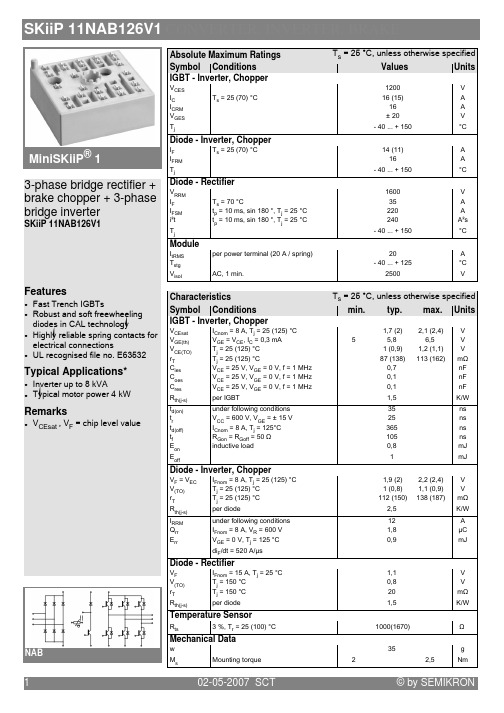
Module
:3 , !
!
- 7(5 @ !
9 0 4 - # (5 = .5 ### > 4(' ('55
Features
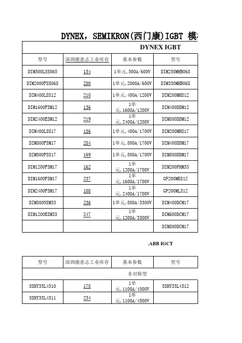
Typical Applications* )
2
02-05-2007 SCT
© by SEMIKRON
SKiiP 11NAB126V1 CONVERTER, INVERTER, BRAKE
Fig. 7 Typ. gate charge characteristic
Fig. 8 Typ. thermal impedance
Fig. 9 Typ. freewheeling diode forward characteristic
Fig. 3 Typ. transfer characteristic
Fig. 4 Reverse bias safe operating area
Fig. 5 Typ. Turn-on /-off energy = f (IC)
Fig. 6 Typ. Turn-on /-off energy = f (RG)
Diode - Rectifier
, ,7 A9
7<=9 : :
J ( - 1 4' 0 < 1 (' 2 < 1 4'5 2 < 1 4'5 2 !
& I0
1 (' 74559 2 404 50* (5 40' 455574%859 &' (0' , , -C E@/ C K-
! Values
DYNEX,SEMIKRON(西门康)IGBT模板各系列参数表
三相整流桥+斩波+三相逆变桥+PTC
型号 SkiiP11NAB065V1 SkiiP14NAB065V1 三相逆变桥+PTC SkiiP14AC065V1 SkiiP26AC065V1 SkiiP27AC065V1
深圳德意志工业库存 295 283
基本参数 12A/600V 25A/600V
型号 SKiiP26NAB065V1 SKiiP38NAB065V1
SKM300GB126D SKM400GB126D
144 275
2单元,300A/1200V 2单元,400A/1200V
SKM400GB176D
标准系列(频率:4-12KHZ) 型号 SKM300GA123D SKM400GA123D SKM500GA123D SKM500GA123DS SKM400GA173D SKM75GB063D SKM100GB063D SKM145GB063DN SKM150GB063D SKM195GB063DN SKM200GB063D SKM300GB063D SKM75GB123D SKM100GB123D SKM145GB123D SKM150GB123D 深圳德意志工业库存 273 108 231 259 235 186 211 290 176 215 102 179 206 124 127 100 基本参数 1单元, 300A/1200V 1单元, 400A/1200V 1单元, 500A/1200V 1单元, 500A/1200V 1单元, 400A/1700V 2单元,75A/600V 2单元,100A/600V 2单元,145A/600V 2单元,150A/600V 2单元,195A/600V 2单元,200A/600V 2单元,300A/600V 2单元,75A/1200V 2单元, 100A/1200V 2单元, 145A/1200V 2单元, 150A/1200V 型号 SKM200GB123D SKM300GB123D SKM400GB123D SKM75GB173D SKM100GB173D SKM150GB173D SKM200GB173D SKM22GD123D SKM40GD123D SKM75GD123D SKM75GD123DL SKM40GD123D SKM75GD123D SKD40GA123D SKD75GA123D SKD100GA123D
SKIIP24NAB126V10_datasheet
(944
A
? 94 ### @ *'4
1
94
? 94 ### Fra bibliotek *('
1
('44
-
0 (' 12
!
min.
typ.
max. Units
*27 6(8 (2* 6(298 -
'
'2<
%2'
-
* 642+8 *2( 6*2*8 -
(4 6&*8 (% 6&78 .D
-$3 : -$3
0 (' 6748 1 0 (' 6748 12 ! ; * .
>
Diode - Inverter, Chopper
:
0 (' 6748 1 0 (' 6748 12 ! ; * .
>
Diode - Rectifier
-: 3: A
Fig. 5 Typ. Turn-on /-off energy = f (IC)
2
Fig. 6 Typ. Turn-on /-off energy = f (RG)
19-10-2004 SEN
© by SEMIKRON
SKiiP 24NAB126V10
Fig. 7 Typ. gate charge characteristic
Diode -Rectifier
- -6 C8
0 &' 2 > 0 (' 1 > 0 *'4 1 > 0 *'4 1
6>?8
SKIIP32NAB12中文资料
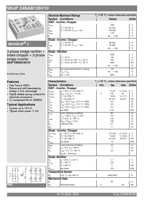
© by SEMIKRON 0898B 16 – 31Absolute Maximum RatingsSymbol Conditions 1)Values Units Inverter V CES V GES I C I CMI F = –I C I FM = –I CMT heatsink = 25 / 80 °Ct p < 1 ms; T heatsink = 25 / 80 °C T heatsink = 25 / 80 °Ct p < 1 ms; T heatsink = 25 / 80 °C600± 2050 / 35100 / 7057 / 38114 / 76V V A A A A Bridge Rectifier V RRM I D I FSMI 2t T heatsink = 80 °Ct p = 10 ms; sin. 180 °, T j = 25 °C t p = 10 ms; sin. 180 °, T j = 25 °C 80025370680V A A A 2s T j T stg V isol AC, 1 min.– 40 . . . + 150– 40 . . . + 1252500°C °C VSKiiP 31 NAB 06MiniSKiiP 3SEMIKRON integrated intelligent Power SKiiP 31 NAB 063-phase bridge rectifier +braking chopper +3-phase bridge inverterCase M3UL recognized file no. E63532•specification of temperature sensor see part A•common characteristics see page B16–3Options•also available with faster IGBTs (type ... 063), data sheet on request1)T heatsink = 25 °C, unless otherwise specified2)CAL = Controlled Axial Lifetime Technology (soft and fast recovery)* For diagrams of the Chopper IGBT please refer to SKiiP 22 NAB 06B 16 – 320698© by SEMIKRONFig. 3Turn-on /-off energy = f (I C )Fig. 4Turn-on /-off energy = f (R G )T j = 125 °C V CE = 300 V V GE = ± 15 V I C = 50 AT j = 125 °C V CE = 300 V V GE = ± 15 V R G = 22 ΩI Cpuls = 50 AV GE = 0 V f = 1 MHzFig. 1Typ. output characteristic, t p = 80 µs; 25 °CFig. 2Typ. output characteristic, t p = 80 µs; 125 °CFig. 5Typ. gate charge characteristic Fig. 6Typ. capacitances vs. V CE© by SEMIKRON0698B 16 – 3Fig. 9Turn-off safe operating area (RBSOA) of the IGBT Fig. 10Safe operating area at short circuit of the IGBTT j= ≤ 150 °C V GE = ± 15 V t sc = ≤ 10 µs L ext < 25 nHT j = ≤ 150 °C V GE = ± 15 VFig. 7Rated current of the IGBT I Cop / I C = f (T h )T j = 150 °C V GE = ≥ 15 V00.20.40.60.81.01.2255075100125150I Cop /I C Mini0607T h [°C]Fig. 11Typ. freewheeling diode forward characteristic Fig. 12Forward characteristic of the input bridge diode mon characteristics of MiniSKiiPMiniSKiiP 600 VMiniSKiiP 3SKiiP 30 NAB 06 SKiiP 31 NAB 06 SKiiP 32 NAB 06 SKiiP 30 NAB 12 SKiiP 31 NAB 12 SKiiP 32 NAB 12CircuitCase M3Layout and connections for thecustomer’s printed circuit board。
SKIIP83AC121T1
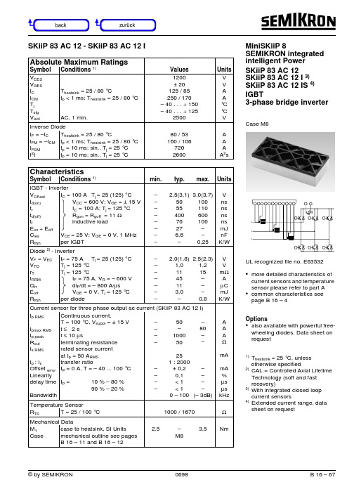
Absolute Maximum RatingsSymbol Conditions 1)Values Units V CES V GES I C I CM T j T stg V isolT heatsink = 25 / 80 °Ct p < 1 ms; T heatsink = 25 / 80 °C AC, 1 min.1200± 20125 / 85250 / 170– 40 . . . + 150– 40 . . . + 1252500V V A A °C °C V Inverse Diode I F = –I C I FM = –I CM I FSMI 2tT heatsink = 25 / 80 °Ct p < 1 ms; T heatsink = 25 / 80 °Ct p = 10 ms; sin., T j = 25 °C t p = 10 ms; sin., T j = 25 °C 80 / 53160 / 1067202600A A A A 2sCharacteristicsSymbol Conditions 1)min.typ.max.UnitsIGBT - InverterV CEsatt d(on)t rt d(off)t fE on + E off C ies R thjhI C = 100 A T j = 25 (125) °C V CC = 600 V; V GE = ± 15 V I C = 100 A; T j = 125 °C R gon = R goff = 11 Ωinductive load V CE = 25 V; V GE = 0 V, 1 MHzper IGBT ––––––––2,5(3,1)505540070276,6–3,0(3,7)100110600100––0,25V ns ns ns ns mJ nF K/W Diode 2) - InverterV F = V EC V TOr TI RRMQ rrE offR thjhI F = 75 A T j = 25 (125) °CT j = 125 °C T j = 125 °C I F = 75 A, V R = – 600 V di F /dt = – 800 A/µs V GE = 0 V, T j = 125 °C per diode –––––––2,0(1,8)1,01145113,0–2,5(2.3)1,215–––0,8V V m ΩA µC mJ K/W Current sensor for three phase output ac current (SKiiP 83 AC 12 I)I p RMS I pmax RMSI p peakR outI s RMSI p : I s Offset error Linearitydelay time BandwidthContinuous current,T = 100 °C, V suppl = ± 15 Vt ≤ 2 s t ≤ 10 µs terminating resistance rated sensor current at I p = 50 A RMStransfer ratioI P = 0 A, T = – 40 ... 100 °CI P =10 % – 80 %90 % – 20 %––––––––50–100050251 : 2000± 0,20,1< 1< 10 – 100–80––––––(– 3dB)A A A ΩmA mA %µs µs kHz Temperature SensorR TS T = 25 / 100 °C1000 / 1670ΩMechanical DataM 1Case case to heatsink, SI Units mechanical outline see pagesB 16 – 11 and B 16 – 122,5–M83,5NmSKiiP 83 AC 12 - SKiiP 83 AC 12 I MiniSKiiP 8SEMIKRON integrated intelligent Power SKiiP 83 AC 12SKiiP 83 AC 12 I 3)SKiiP 83 AC 12 IS 4)IGBT3-phase bridge inverterCase M8UL recognized file no. E63532•more detailed characteristics ofcurrent sensors and temperature sensor please refer to part A •common characteristics see page B 16 – 4Options•also available with powerful free-wheeling diodes. Data sheet on request1)T heatsink = 25 °C, unless otherwise specified2)CAL = Controlled Axial Lifetime Technology (soft and fast recovery)3)With integrated closed loop current sensors4)Extended current range, data sheet on request~~~0408012016002001234517V13V15V 11V 9V7VI C [A]V CE [V]83AC120104080120160200123459V7V13V15V 17V11V I C [A]83AC1202V CE [V]02468101214161820600V800VV GE [V]83AC1205Q G [nC]200400600800Fig. 3Turn-on /-off energy = f (I C )Fig. 4Turn-on /-off energy = f (R G )I Cpuls = 100 AV GE = 0 V f = 1 MHzFig. 1Typ. output characteristic, t p = 80 µs; 25 °C Fig. 2Typ. output characteristic, t p = 80 µs; 125 °CFig. 5Typ. gate charge characteristic Fig. 6Typ. capacitances vs. V CE T j = 125 °C V CE = 600 V V GE = ± 15 V I C = 100 AT j = 125 °C V CE = 600 V V GE = ± 15 V R G = 11 ΩT j = ≤ 150 °C V GE = ± 15 V t sc = ≤ 10 µs L ext < 25 nHT j = ≤ 150 °C V GE = ± 15 VT j = 150 °C V GE = ≥ 15 VFig. 9Turn-off safe operating area (RBSOA) of the IGBT Fig. 10Safe operating area at short circuit of the IGBTFig. 7Rated current of the IGBT I Cop / I C = f (T h)00.20.40.60.81.01.2255075100125150I Cop /I C Mini1207T h [°C]00,511,522,550010001500I Cpuls /I C Mini1209V CE [V]02468101250010001500Note:*Allowed nu mbers of short ci r cuit:<1000*Time between short circuit:>1sI Csc /I CN Mini1210V CE [V]Fig. 11Typ. freewheeling diode forward characteristic Fig. 12Forward characteristic of the input bridge diode MiniSKiiP 1200 VMiniSKiiP 8Inverter part SKiiP 82 AC 06 ...SKiiP 83 AC 06 ...SKiiP 81 AC 12 ...SKiiP 82 AC 12 ...SKiiP 83 AC 12 ...Circuit Case M8Note:The current sensors areavailable only by option IMiniSKiiP 8 Inverter partSKiiP 82 AC 06 ... SKiiP 83 AC 06 ... SKiiP 81 AC 12 ... SKiiP 82 AC 12 ... SKiiP 83 AC 12 ...Case M8Layout and connections for thecustomer’s printed circuit boardpin connection optional1T+2T-3~1ET1CB14GB15GT16–EB1EB2EB37+CT1CT2CT38GB29GT210~2ET2CB211+CT1CT2CT312–EB1EB2EB313GT314~3ET3CB315GB316K1 for ~1X17K2 for ~1X18S1 for ~1X19S2 for ~1X20K1 for ~2X21K2 for ~2X22S1 for ~2X23S2 for ~2X24K1 for ~3X25K2 for ~3X26S1 for ~3X27S2 for ~3X。
SKIIP31NAB12T11中文资料

µV & 7M & 9&( 9 9*( 9 ,& $
ms31nab12t11.xls - 3
ms31nab12t11.xls - 4
Eon
15
Eon
10 Eoff 5 E 0 0 IC 20 40 60 A 80 E
10
5
Eoff
0LQL6.LL3
6.LL3 1$% 7 6.LL3 1$% 7 6.LL3 1$% 7
E\ 6(0,.521
7ROHUDQ.H ,62 I
E\ 6(0,.521
元器件交易网
6.LL3 1$% 7
70 A 60 50 40 30 20 10 IC 0 0 VCE 1 2 3 17V 15V 13V 11V 9V 7V
ms31nab12t11.xls - 1
70 A 60 50 40 30 20 10 IC 0 17V 15V 13V 11V 9V 7V
)LJ 7\S IUHHZKHHOLQJ GLRGH IRUZDUG .KDUD.WHULVWL.
E\ 6(0,.521
)LJ )RUZDUG .KDUD.WHULVWL. RI WKH LQSXW EULGJH GLRGH
元器件交易网
&DVH 0
%ULGJH 5H.WLILHU 7KHDWVLQN & WS PV VLQ 7M WS PV VLQ 7M
& &
$& PLQ
&KDUD.WHULVWL.V
6\PERO &RQGLWLRQV
SK系列操作说明书
于主体故障引起的停产等次生性损失,我公司概不负责。
2
目录
1. 本书的使用方法··················································· 5 2. 使用时的注意事项················································· 6 3. 产品构成························································· 11 4. 各部位的名称····················································· 12 5. 本体模块的连接和设备安装
将不能进行称重。具体请参考 5-2-2 章节。
排除静电的影响
!
·当测量物的包装袋、容器等使用绝缘物时,所带的静电会导致测量发生误差。
请使用混有导电材料的风防盖,或者金属容器。
·为了防止静电损坏称重模块,请将模块通过设备外框接地。
排除风的影响
·称重部的周围请一定做好防风罩,排除风的影响。当包装袋或容器体积增大
! 警告
不要在温度、湿度过高的环境下使用 ·可能导致触电或者电路短路。 ·本机的使用温湿度范围是:10~30℃,80%RH 以下。 本机的 DC24V 电源请专门配置,请不要与其他的 DC24V 驱动机器共用 ·如果从其他驱动机器的电线侵入的强干扰,可能导致本机的误动作。
!
·如果从其他驱动器带来冲击电流,可能导致本机无法正常启动。 ·根据本机的电路结构,也可能导致其他驱动器无法正常动作。
SKiiP_39AC12T4V1_25231450
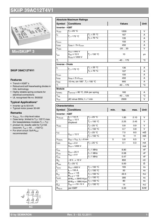
© by SEMIKRON
SKiiP 39AC12T4V1
pinout, dimensions
pinout
This is an electrostatic discharge sensitive device (ESDS), international standard IEC 60747-1, Chapter IX * The specifications of our components may not be considered as an assurance of component characteristics. Components have to be tested for the respective application. Adjustments may be necessary. The use of SEMIKRON products in life support appliances and systems is subject to prior specification and written approval by SEMIKRON. We therefore strongly recommend prior consultation of our staff.
© by SEMIKRON
Rev. 3 – 02.12.2011
5
Fig. 3: Typ. turn-on /-off energy = f (IC)
Fig. 4: Typ. turn-on /-off energy = f (RG)
Fig. 5: Typ. transfer characteristic
Fig. 6: Typ. gate charge characteristic
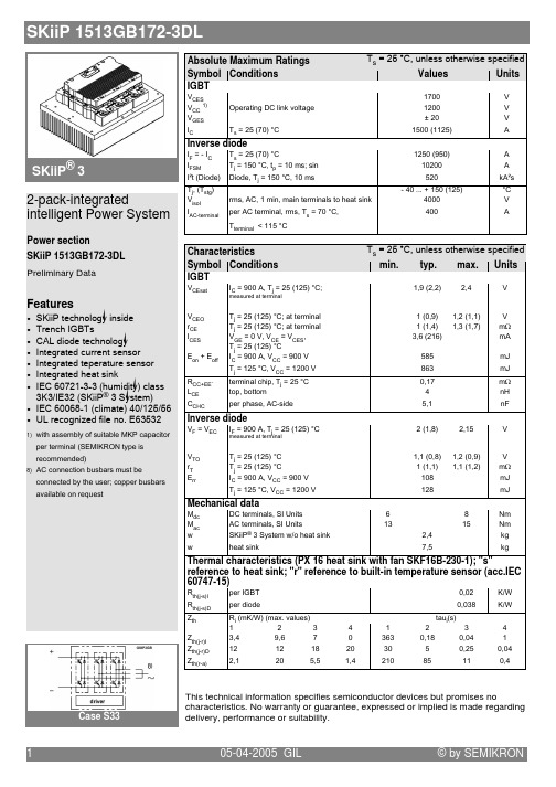
SKIIP1513GB172-3DL中文资料
Gate driver features
68 ) 5
N
4
?
)
B&5 ;
!"#$%&'&' ( ) *
''+ '$ (, '
@$ @ ;+ @8 @B
@%$ 24 2 ( *
51
$. @ 4
;
( *
)
+ (? )? $ *
? F = %/" >? %" )
%$/" (E/"* %"$"" /$"
G
F? ( *
& ." 333 H %/" (%$/*
>
@
)? ? % ) ? )
)
."""
@
&
)
) ? )? = #" >?
( *
8;
8;
;
( * 4
;
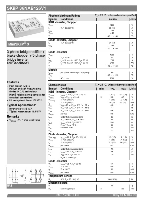
SKiiP_36NAB126V1_25230120
+ +6 B8
, 1 &' / < 1 (' 2 < 1 -'4 2 < 1 -'4 2
6<=8
!
Temperature Sensor
& I/
1 (' 6-448 2
Mechanical Data
! &% *+ ! ,
!
-./' *0 Remarks +$ / + 1 ! ) )
NAB
Absolute Maximum Ratings Symbol Conditions IGBT - Inverter, Chopper
SKiiP 36NAB126V1 CONVERTER, INVERTER, BRAKE
MiniSKiiP® 3 3-phase bridge rectifier + brake chopper + 3-phase bridge inverter
SKiiP 36NAB126V1
Features
6<=8
!
6 8
68 $
+ 1 %44 +/ +$ 1 ; -' + , 1 74 / < 1 -('2 1 1 ? C )
$
Diode - Inverter, Chopper
Fig. 10 Typ. input bridge forward characteristic
3
08-07-2009 LAN
20NAB12中文资料
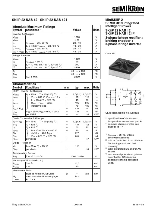
© by SEMIKRON 000131 B 16 – 53Absolute Maximum RatingsSymbolConditions 1)Values Units Inverter & Chopper V CES V GES I C I CMI F = –I CI FM = –I CM T heatsink = 25 / 80 °Ct p < 1 ms; T heatsink = 25 / 80 °C T heatsink = 25 / 80 °C t p < 1 ms; T heatsink = 25 / 80 °C 1200± 2023 / 1546 / 3024 / 1748 / 34V V A A A A Bridge Rectifier V RRMI DI FSM I 2t T heatsink = 80 °C t p = 10 ms; sin. 180 °, T j = 25 °C t p = 10 ms; sin. 180 °, T j = 25 °C 1500257002400V A A A 2s T j T stg V isol AC, 1 min.– 40 . . . + 150– 40 . . . + 1252500°C °C VSKiiP 22 NAB 12 - SKiiP 22 NAB 12 I MiniSKiiP 2SEMIKRON integrated intelligent Power SKiiP 22 NAB 12SKiiP 22 NAB 12 I 3)3-phase bridge rectifier + braking chopper +3-phase bridge inverterCase M2UL recognized file no. E63532•specification of shunts and temperature sensor see part A •common characteristics see page B 16 – 41)T heatsink = 25 °C, unless otherwise specified2)CAL = Controlled Axial Lifetime Technology (soft and fast recovery)3)With integrated DC and/or AC shunts4)accuracy of pure shunt, please note that for DC shunt no separate sensing contact is used.B 16 – 54000131© by SEMIKRON= 600 V = ± 15 V = 600 V = ± 15 V = 52 ΩI Cpuls = 15 AV GE = 0 V f = 1 MHzFig. 1Typ. output characteristic, t p = 80 µs; 25 °C Fig. 2Typ. output characteristic, t p = 80 µs; 125 °CFig. 5Typ. gate charge characteristic Fig. 6Typ. capacitances vs. V CEB 16 – 40698© by SEMIKRONT j = ≤ 150 °C V GE = ± 15 V t sc = ≤ 10 µs L ext < 25 nHT j = ≤ 150 °C V GE = ± 15 VT j = 150 °C V GE = ≥ 15 VFig. 9Turn-off safe operating area (RBSOA) of the IGBT Fig. 10Safe operating area at short circuit of the IGBTFig. 7Rated current of the IGBT I Cop / I C = f (T h)00.20.40.60.81.01.2255075100125150I Cop /I C Mini1207T h [°C]00,511,522,550010001500I Cpuls /I C Mini1209V CE [V]02468101250010001500Note:*Allowed nu mbers of short ci r cuit:<1000*Time between short circuit:>1sI Csc /I CN Mini1210V CE [V]Fig. 11Typ. freewheeling diode forward characteristic Fig. 12Forward characteristic of the input bridge diode MiniSKiiP 1200 VMiniSKiiP 2SKiiP 20 NAB 06 ... SKiiP 21 NAB 06 ... SKiiP 20 NAB 12 ... SKiiP 22 NAB 12 ...CircuitCase M2Layout and connections for thecustomer’s printed circuit boardNote:The shunts are availableonly by option I-DC/AIsw0wIsv0v0uIsuI+B-TL3L1L2+rect-DC-rectg1UVW+T+DCg3g5g2g6g4gB+B-BHauptanschlußpower connectorcontrol pinSteueranschluß。
SEMIKRON 电路板产品说明书
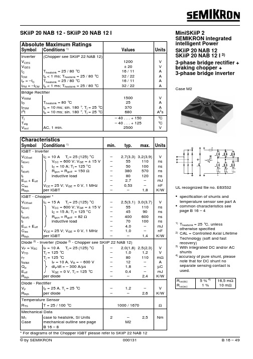
000131Absolute Maximum RatingsSymbol Conditions 1)ValuesUnitsInverter (Chopper see SKiiP 22 NAB 12)V CES V GES I C I CMI F = –I C I FM = –I CMT heatsink = 25 / 80 °Ct p < 1 ms; T heatsink = 25 / 80 °C T heatsink = 25 / 80 °Ct p < 1 ms; T heatsink = 25 / 80 °C1200± 2016 / 1132 / 2216 / 1132 / 22V V A A A A Bridge Rectifier V RRMI DI FSM I 2tT heatsink = 80 °C t p = 10 ms; sin. 180 °, T j = 25 °C t p = 10 ms; sin. 180 °, T j = 25 °C 150025370680V A A A 2s T j T stg V isol AC, 1 min.– 40 . . . + 150– 40 . . . + 1252500°C °C VSKiiP 20 NAB 12 - SKiiP 20 NAB 12 I MiniSKiiP 2SEMIKRON integrated intelligent Power SKiiP 20 NAB 12SKiiP 20 NAB 12 I 3)3-phase bridge rectifier +braking chopper +3-phase bridge inverterCase M2UL recognized file no. E63532•specification of shunts andtemperature sensor see part A •common characteristics see page B 16 – 41)T heatsink = 25 °C, unless otherwise specified2)CAL = Controlled Axial Lifetime Technology (soft and fast recovery)3)With integrated DC and/or AC shunts4) accuracy of pure shunt, please note that for DC shunt no separate sensing contact is used.R cs(dc)R cs(ac)5 % 4)1 %16,5 m Ω10 m Ω000131Fig. 3Turn-on /-off energy = f (I C )Fig. 4Turn-on /-off energy = f (R G )T j = 125 °C V CE = 600 V V GE = ± 15 V I C = 10 AT j = 125 °C V CE = 600 V V GE = ± 15 V R G = 150 ΩI Cpuls = 10 AV GE = 0 V f = 1 MHzFig. 1Typ. output characteristic, t p = 80 µs; 25 °CFig. 2Typ. output characteristic, t p = 80 µs; 125 °CFig. 5Typ. gate charge characteristic Fig. 6Typ. capacitances vs. V CE0698T j = ≤ 150 °C V GE = ± 15 V t sc = ≤ 10 µs L ext < 25 nHT j = ≤ 150 °C V GE = ± 15 VT j = 150 °C V GE = ≥ 15 VFig. 9Turn-off safe operating area (RBSOA) of the IGBT Fig. 10Safe operating area at short circuit of the IGBTFig. 7Rated current of the IGBT I Cop / I C = f (T h)00.20.40.60.81.01.2255075100125150I Cop /I C Mini1207T h [°C]00,511,522,550010001500I Cpuls /I C Mini1209V CE [V]02468101250010001500Note:*Allowed nu mbers of short ci r cuit:<1000*Time between short circuit:>1sI Csc /I CN Mini1210V CE [V]Fig. 11Typ. freewheeling diode forward characteristic Fig. 12Forward characteristic of the input bridge diode MiniSKiiP 1200 VMiniSKiiP 2SKiiP 20 NAB 06 ... SKiiP 21 NAB 06 ... SKiiP 20 NAB 12 ... SKiiP 22 NAB 12 ...CircuitCase M2Layout and connections for thecustomer’s printed circuit boardNote:The shunts are availableonly by option I-DC/AIsw0wIsv0v0uIsuI+B-TL3L1L2+rect-DC-rectg1UVW+T+DCg3g5g2g6g4gB+B-BHauptanschlußpower connectorcontrol pinSteueranschluß。
SKIIP23NAB126V1中文资料

1 (' 2/
! Values
*(44 8* 6&*7 '4 ; (4 = 84 ### > *'4
Units
, , 2 2 , @ 2 2 ,
Diode - Inverter, Chopper
MiniSKiiP 2 3-phase bridge rectifier + brake chopper + 3-phase bridge inverter
Fig. 8 Typ. thermal impedance
Fig. 9 Typ. freewheeling diode forward characteristic
Fig. 10 Typ. input bridge forward characteristic
3
02-05-2007 SCT
© by SEMIKRON
元器件交易网
SKiiP 23NAB126V1 CONVERTER, INVERTER, BRAKE
Absolute Maximum Ratings Symbol Conditions IGBT - Inverter, Chopper
,$3 9 ,$3 < 1 (' 6.47 2 ! : * -
Fig. 6 Typ. Turn-on /-off energy = f (RG)
2
02-05-2007 SCT
© by SEMIKRON
元器件交易网
SKiiP 23NAB126V1 CONVERTER, INVERTER, BRAKE
Fig. 7 Typ. gate charge characteristic
SKiiP_39AC12T4V1_25231450
Inverter - IGBT
MiniSKiiP® 3
VGES tpsc Tj IF IFnom
Inverse - Diode
SKiiP 39AC12T4V1 Features
• Trench 4 IGBT´s • Robust and soft freewheeling diodes in CAL technology • Highly reliable spring contacts for electrical connections • UL recognised file no. E63532
© by SEMIKRON
Rev. 3 – 02.12.2011
5
AC 2 Rev. 3 – 02.12.2011 © by SEMIKRON
SKiiP 39AC12T4V1
Fig. 1: Typ. output characteristic, inclusive RCC'+ EE'
Fig. 2: Rated current vs. temperature IC = f (TS)
SKiiP ቤተ መጻሕፍቲ ባይዱ9AC12T4V1
Absolute Maximum Ratings Symbol
VCES IC ICnom ICRM ICRM = 3 x ICnom VCC = 800 V VGE ≤ 15 V VCES ≤ 1200 V
Conditions
Tj = 25 °C Tj = 175 °C Ts = 25 °C Ts = 70 °C
2.5
Nm g
Temperatur Sensor R100 R(T)
Typical Applications*