icepak网格划分方法 meshing
基于Icepak的MW级大功率变流器热设计
基于Icepak的MW级大功率变流器热设计苗亚;翟志华;王彤;周辉;田雷【摘要】从主电路损耗计算、热流路径分析、散热通道设计、热仿真分析、试验验证等几个方面详细介绍了MW级大功率变流器的热设计,给出了功率元件损耗计算公式,介绍了热传导路径、散热系统参数计算方法和热设计思路,通过Icepak软件进行了热仿真,最后通过试验验证了所述热设计方法的准确性.【期刊名称】《电气传动》【年(卷),期】2014(044)007【总页数】5页(P58-62)【关键词】MW级大功率变流器;热设计;散热系统设计;仿真分析【作者】苗亚;翟志华;王彤;周辉;田雷【作者单位】国电南瑞科技股份有限公司,江苏南京 210061;国电南瑞科技股份有限公司,江苏南京 210061;国电南瑞科技股份有限公司,江苏南京 210061;国电南瑞科技股份有限公司,江苏南京 210061;国电南瑞科技股份有限公司,江苏南京210061【正文语种】中文【中图分类】TM46近年来随着大功率传动和新能源的高速发展,用于能量变换的变流器容量越来越大,功率密度越来越高。
在大功率变流器设计中,常用的冷却方式一般为强迫风冷和液体冷却,液体冷却的散热效果更好。
但液体冷却结构复杂,实现难度较大,成本高,可靠性比风冷低。
因此,本文所设计大功率变流器采用强迫风冷进行散热。
本文针对MW级大功率变流器进行热设计,并在此基础上进行了仿真分析和试验,通过风机和散热器参数的优化设计提高了大功率变流器的散热效率和系统稳定性。
1 主电路损耗分析分析与计算功率器件损耗是散热系统设计的前提。
对MW级大功率变流器而言,功率单元的设计一般以桥臂为单元进行,即每个散热器上安装一个桥臂的主功率元件。
通常情况下,IGBT模块一般包括IGBT和并联二极管,IGBT和并联二极管的损耗均包括通态损耗和开关损耗。
在正弦脉宽调制模式下,考虑温度和死区时间对IGBT和二极管通态损耗的影响,IGBT的通态损耗有[1]:并联二极管的通态损耗有:其中式中:td为死区时间;Ts为开关周期;M为调制比;φ为电流与电压的相角;rCE,VCEO分别为IGBT正向导通电阻和擎住电压;rD,VDO分别为二极管通态电阻和门槛电压;rCE_25°C,rD_25°C分别为IGBT和二极管25 ℃时的额定通态电阻;VCE_25°C,VD_25°C分别为IGBT和二极管25℃时的额定导通压降;Tj1,Tj2分别为IGBT和二极管的实际结温;Kr_Tr为温度对IGBT通态电阻影响的温度系数;Kr_D为温度对二极管通态电阻影响的温度系数;KV_Tr为温度对IGBT导通压降影响的温度系数;KV_D为温度对二极管导通压降影响的温度系数。
Icepak-Intro_14.5_L07_Meshing-non-conformal-HD
• Use the Macro Automatic Case Check Tool to detect teometric Scales in Electronics Systems
•
Packages (microns)
Wirebonds, traces, solder balls and bumps substrates, vias, die, and mold
•
Board (cm)
Power, ground, and signal planes, through holes, packages, mounting holes, and the board itself
• Note: creation of an assembly does not automatically enable separate meshing; the “Mesh separately” field must be checked on • N/C assemblies are colored in purple in the graphic display, and also in the model tree
11
© 2012 ANSYS, Inc.
December 5, 2012
Release 14.5
Assembly Rules: Assembly-assembly intersections
• Multiple assemblies can be Non-Conformal assemblies provided the bounding boxes of the assemblies: do not intersect (overlap) • Use the Macro Automatic Case Check Tool to detect the assembly-assembly intersections.
Icepak实例详解(中文)
目录什么是Icepak? (2)程序结构 (2)软件功能 (3)练习一翅片散热器 (8)练习二辐射的块和板 (43)练习三瞬态分析练习四笔记本电脑练习五改进的笔记本电脑练习六 IGES模型的输入练习七非连续网格•练习八 Zoom-in 建模练习1 翅片散热器介绍本练习显示了如何用Icepak做一个翅片散热器。
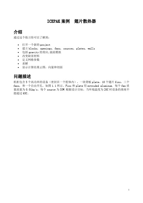
通过这个练习你可以了解到:•打开一个新的project•建立blocks, openings, fans, sources, plates, walls•包括gravity的效应,湍流模拟•改变缺省材料•定义网格参数•求解•显示计算结果云图,向量和切面问题描述机柜包含5个高功率的设备(密封在一个腔体内),一块背板plate,10个翅片fins,三个fans, 和一个自由开孔,如图1.1所示。
Fins和plate用extruded aluminum. 每个fan质量流量为0.01kg/s,每个source为33W.根据设计目标,当环境温度为20C时设备的基座不能超过65C。
图 1.1:问题描述步骤 1: 创建一个新的项目1. 启动Icepak, 出现下面窗口。
2. 点击New打开一个新的Icepak project.就会出现下面的窗口:3. 给定一个项目的名称并点击Create.(a) 本项目取名为fin,(b) 点击Create.Icepak就会生成一个缺省的机柜,尺寸为 1 m ⨯1 m ⨯1 m。
你可以用鼠标左键旋转机柜,或用中键平移,右键放大/缩小。
还可以用Home position 回来原始状态。
4. 修改problem定义,包括重力选项。
Problem setup Basic parameters(a) 打开Gravity vector选项,保持缺省值。
(b) 保持其它缺省设置。
(c) 点击Accept保存设置。
步骤 2: 建立模型建模之前,你首先要改变机柜的大小。
然后建立一块背板和开孔,接下来就是建立风扇,翅片和发热设备。
Icepak案例
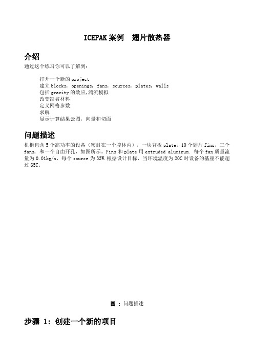
ICEPAK案例翅片散热器介绍通过这个练习你可以了解到:打开一个新的project建立blocks, openings, fans, sources, plates, walls包括gravity的效应,湍流模拟改变缺省材料定义网格参数求解显示计算结果云图,向量和切面问题描述机柜包含5个高功率的设备(密封在一个腔体内),一块背板plate,10个翅片fins,三个fans, 和一个自由开孔,如图所示。
Fins和plate用extruded aluminum. 每个fan质量流量为0.01kg/s,每个source为33W.根据设计目标,当环境温度为20C时设备的基座不能超过65C。
图 :问题描述步骤 1: 创建一个新的项目1. 启动Icepak, 出现下面窗口。
2. 点击New打开一个新的Icepak project.就会出现下面的窗口:3. 给定一个项目的名称并点击Create.(a) 本项目取名为fin,(b) 点击Create.Icepak就会生成一个缺省的机柜,尺寸为 1 m 1 m 1 m。
你可以用鼠标左键旋转机柜,或用中键平移,右键放大/缩小。
还可以用Home position 回来原始状态。
4. 修改problem定义,包括重力选项。
Problem setup Basic parameters(a) 打开Gravity vector选项,保持缺省值。
(b) 保持其它缺省设置。
(c) 点击Accept保存设置。
步骤 2: 建立模型建模之前,你首先要改变机柜的大小。
然后建立一块背板和开孔,接下来就是建立风扇,翅片和发热设备。
1. 改变机柜大小,在Cabinet窗口下.Model Cabinet另外:你也可以打开Cabinet面板,通过点击Edit窗口.(a) 在Cabinet面板下, 点击Geometry.(b) 在Location下, 输入下面的坐标:xS xEyS0yE(c) 点击Done.(d) 点击Scale to fit来看整个绘图窗口。
Icepak培训教程

目录什么是Icepak (2)程序结构 (2)软件功能 (3)练习1 翅片散热器 (6)练习2 辐射的块和板 (41)练习3 瞬态分析 (56)练习4 笔记本电脑 (75)练习5 修改的笔记本电脑 (104)练习6 由IGES导入的发热板模型 (114)练习7 非连续网格 (138)练习8 Zoom-in建模 (149)什么是IcepakIcepak是强大的 CAE 仿真软件工具,它能够对电子产品的传热,流动进行模拟,从而提高产品的质量,大量缩短产品的上市时间。
Icepak能够计算部件级,板级和系统级的问题。
它能够帮助工程师完成用试验不可能实现的情况,能够监控到无法测量的位置的数据。
Icepak采用的是FLUENT计算流体动力学 (CFD) 求解引擎。
该求解器能够完成灵活的网格划分,能够利用非结构化网格求解复杂几何问题。
多点离散求解算法能够加速求解时间。
Icepak提供了其它商用热分析软件不具备的特点,这些特点包括:图软件架构•非矩形设备的精确模拟•接触热阻模拟•各向异性导热率•非线性风扇曲线•集中参数散热器•外部热交换器•辐射角系数的自动计算程序结构Icepak软件包包含如下内容:•Icepak, 建模,网格和后处理工具•FLUENT, 求解器Icepak本身拥有强大的建模功能。
你也可以从其它 CAD 和 CAE 软件包输入模型. Icepak然后为你的模型做网格, 网格通过后就是进行CFD求解。
计算结果可以在Icepak中显示, 如图所示.软件功能所有的功能均在Icepak界面下完成。
总述•鼠标控制的用户界面o鼠标就能控制模型的位置,移动及改变大小o误差检查•灵活的量纲定义•几何输入IGES, STEP, IDF, 和 DXF格式•库功能•在线帮助和文档o完全的超文本在线帮助 (包括理论和练习册)•支持平台o UNIX 工作站o Windows NT 2000/XP 的PC机建模•基于对象的建模o cabinets 机柜o networks 网络模型o heat exchangers 热交换器o wires 线o openings 开孔o grilles 过滤网o sources 热源o printed circuit boards (PCBs) PCB板o enclosures 腔体o plates 板o walls 壁o blocks 块o fans (with hubs) 风扇o blowers 离心风机o resistances 阻尼o heat sinks 散热器o packages 封装•macros 宏o JEDEC test chambers JEDEC试验室o printed circuit board (PCB)o ducts 管道o compact models for heat sinks 简化的散热器•2D object shapes 2D模型o rectangular 矩形o circular 圆形o inclined 斜板o polygon 多边形板•complex 3D object shapes 3D模型o prisms 四面体o cylinders 圆柱o ellipsoids 椭圆柱o elliptical and concentric cylinders 椭圆柱o prisms of polygonal and varying cross-section 多面体o ducts of arbitrary cross-section 任意形状的管道网格•自动非结构化网格生成o六面体,四面体,五面体及混合网格•网格控制o粗网格生成o细网格生成o网格检查o非连续网格材料•综合的材料物性数据库•各向异性材料•属性随温度变化的材料物理模型•层流/湍流模型•稳态/瞬态分析•强迫对流/自然对流/混合对流•传导•流固耦合•辐射•体积阻力•混合长度方程(0-方程), 双方程(标准-方程), RNG- , 增强双方程 (标准-带有增强壁面处理), 或Spalart-Allmaras湍流模型•接触阻尼•体积阻力模型•非线性风扇曲线•集中参数的fans, resistances, and grilles边界条件•壁和表面边界条件:热流密度, 温度, 传热系数, 辐射,和对称边界条件•开孔和过滤网•风扇•热交换器•时间相关和温度相关的热源•随时间变化的环境温度求解引擎对于求解器FLUENT,是采用的有限体积算法。
icepak-meshing-网格划分

Re-
No
examine
the Mesh
OKY?es
Solve
Examine mesh using 物体的surface plots and cut planes use x,y,z count 对物体进行划分 设定物体周围的Low and High element size/ratio Inward height/ratio to refine within an object set Max X, Y, Z sizes
Solid region
Fluid Region
Dx1 Dx2 Dx3
E-13
Global settings (3)
Min elements on cylinder face Min elements on triangle face Additional Optional Flags
• No “O” grid Prevents “O” meshing on all objects
• Mesh assemblies separately 选择它, Icepak 将对assemblies创建 non-conformal and put a finer mesh on the objects within the assembly
E-14
Recommendations
Min elements in fluid gap • Either 2 or 3 • More than 4 may refine the mesh in unwanted regions
E-9
Default settings
Mesher Type • Hexa-Unstructured, Hexa-Cartesian, Tetrahedral,mesher-hd(hexdominant mesher六面体核心网格) • 只有六面体核心网格才能对CAD objects进行网格划分
icepak-meshing-网格划分解析

Eபைடு நூலகம்6
Hexahedral meshing
结构化网格 非结构化网格
台阶状近似几何 不正确的几何面积 远场网格不得不加密 网格数量多,精度差
E-7
真实几何 正确的几何面积 只在需要的地方加密网格 网格数量少,精度好
Hexahedral meshing:structured and unstructured
E-11
Global settings (1)
Normal Mesher – Provides an acceptable mesh for most situations Coarse Mesher – Provides a coarse mesh Mesher default settings include: Min elements in fluid gap - Minimum number of cells in between adjacent faces
E-9
Default settings
Mesher Type Hexa-Unstructured, Hexa-Cartesian, Tetrahedral,mesher-hd(hexdominant mesher六面体核心网格) 只有六面体核心网格才能对CAD objects进行网格划分 Max X, Max Y, Max Z Control the size of the largest cell allowable in the background mesh Object Params Individual parameters
• Use coarse mesh for initial solutions • Use suitably refined mesh for final solution
Icepak-Intro_14.5_L06_Meshing_Overview
• Min elements on edge
• The mesher tries to force this value on all edges • Should be either 1 or 2
• Max Size ratio
• This is the maximum growth rate of elements into the fluid off of a surface • Should not exceed 10 - recommended between 2 (smaller models) and 5 (large models)
Panels to Generate, Display, Check Quality, and Export mesh Buttons to:
• Load existing mesh • Generate new mesh • Terminate mesh program
Global Mesh Control Settings
N/C assemblies: A - Hexa cartesian B - Mesher-HD
6
© 2012 ANSYS, Inc.
December 5, 2012
Release 14.5
Chapter Contents
• Icepak Mesh Overview • Fundamentals of Icepak Mesh
3 © 2012 ANSYS, Inc. December 5, 2012 Release 14.5
Mesh Overview: User Controls
• Non-conformal Mesh
icepak网格划分方法 meshing
Refine the Mesh
Generate new Mesh
Re-
No
examine
the Mesh
OKY?esBiblioteka SolveExamine mesh using surface plots and cut planes Always check quality using diagnostic Maintain sufficient mesh density to capture physics
▪ If the separation is set higher than 10%, but less than 50% of the smallest dimension, Icepak will prompt you to either - Stop meshing and change manually - Continue and change automatically to 10% - Ignore and continue
Panels to generate, Display, Check quality, and Export to Ideas
Default Settings mesher type, background mesh settings
Global Settings for refining mesh
▪ If the separation is larger than 50%, Icepak will prompt you to - Stop meshing - Continue and change automatically
▪ The separation can be set either in the meshing panel or in the settings configuration panel
Icepak案例
ICEPAK案例翅片散热器介绍通过这个练习你可以了解到:•打开一个新的project•建立blocks, openings, fans, sources, plates, walls•包括gravity的效应,湍流模拟•改变缺省材料•定义网格参数•求解•显示计算结果云图,向量和切面问题描述机柜包含5个高功率的设备(密封在一个腔体内),一块背板plate,10个翅片fins,三个fans, 和一个自由开孔,如图1.1所示。
Fins和plate用extruded aluminum. 每个fan质量流量为0.01kg/s,每个source为33W.根据设计目标,当环境温度为20C时设备的基座不能超过65C。
图 1.1:问题描述步骤 1: 创建一个新的项目1. 启动Icepak, 出现下面窗口。
2. 点击New打开一个新的Icepak project.就会出现下面的窗口:3. 给定一个项目的名称并点击Create.(a) 本项目取名为fin,(b) 点击Create.Icepak就会生成一个缺省的机柜,尺寸为 1 m ⨯1 m ⨯1 m。
你可以用鼠标左键旋转机柜,或用中键平移,右键放大/缩小。
还可以用Home position 回来原始状态。
4. 修改problem定义,包括重力选项。
Problem setup Basic parameters(a) 打开Gravity vector选项,保持缺省值。
(b) 保持其它缺省设置。
(c) 点击Accept保存设置。
步骤 2: 建立模型建模之前,你首先要改变机柜的大小。
然后建立一块背板和开孔,接下来就是建立风扇,翅片和发热设备。
1. 改变机柜大小,在Cabinet窗口下.Model Cabinet另外:你也可以打开Cabinet面板,通过点击Edit窗口.(a) 在Cabinet面板下, 点击Geometry.(b) 在Location下, 输入下面的坐标:xS -0.025 xE 0.075yS 0 yE 0.25zS 0 zE 0.356(c) 点击Done.(d) 点击Scale to fit来看整个绘图窗口。
Icepak网格划分

• •
Low/High end ratio
– 平面两侧单元的增长率
Inward height/ratio
Inward height & ratio
米克网 © 2010
IV Per‐object网格设置‐圆形平面
圆形平面– 如: 矩形fan,圆形平面resistance等 • Diameter count – 经过直径的网格数量 • Low/High End heights and ratios • Inward height/ratio • Outward height/ratio – 背离object方向上的网格单元高度和增长率
米克网 © 2010
•
• • • •
Δx1 Δx2
III全局网格设置‐ HD Mesher
HD Mesher特有的选项: • Allow stair‐stepped meshing • Allow Multi‐level Meshing
• 可以用来对Hexa mesher无法划分的模型进行网格划 分
•
•
•
米克网 © 2010
Object params
III全局网格设置‐ Hexahedral
• Mesh parameters – Normal Mesher:大多情况下可以生成合理 的background grid – Coarse Mesher:生成比较粗糙的网格,可 以进一步在局部细化 Min elems in gap – Fluid gap中的最小网格数量 – 建议设置设置为2或3 – 大于4后可能在不必要的区域细化网格 • 如果希望对局部网格进一步细化可以 使用Object parameters来设置 Min elems on edge – 位于Object边上的最小网格数量 – 建议设置不大于2 • 可以使用Object parameters对局部进 一步细化
Icepak培训中文教程[整理版]
![Icepak培训中文教程[整理版]](https://img.taocdn.com/s3/m/b5291b2da0116c175e0e4896.png)
Icepak培训中文教程[整理版] 目录什么是Icepak? (2)程序结构 (2)软件功能 (3)练习一翅片散热器 (8)练习二辐射的块和板 (43)1.1 什么是Icepak?Icepak 是强大的 CAE 仿真软件工具,它能够对电子产品的传热,流动进行模拟,从而提高产品的质量,大量缩短产品的上市时间。
Icepak 能够计算部件级,板级和系统级的问题。
它能够帮助工程师完成用试验不可能实现的情况,能够监控到无法测量的位置的数据。
Icepak 采用的是 FLUENT 计算流体动力学 (CFD) 求解引擎。
该求解器能够完成灵活的网格划分,能够利用非结构化网格求解复杂几何问题。
多点离散求解算法能够加速求解时间。
Icepak 提供了其它商用热分析软件不具备的特点,这些特点包括:, 非矩形设备的精确模拟, 接触热阻模拟, 各向异性导热率, 非线性风扇曲线, 集中参数散热器, 外部热交换器, 辐射角系数的自动计算1.2 程序结构Icepak 软件包包含如下内容:, Icepak, 建模,网格和后处理工具, FLUENT, 求解器图 1.2.1: 软件架构Icepak 本身拥有强大的建模功能。
你也可以从其它 CAD 和 CAE 软件包输入模型. Icepak 然后为你的模型做网格, 网格通过后就是进行CFD求解。
计算结果可以在Icepak中显示, 如图 1.2.1所示.1.3 软件功能所有的功能均在Icepak 界面下完成。
1.3.1 总述, 鼠标控制的用户界面o 鼠标就能控制模型的位置,移动及改变大小o 误差检查, 灵活的量纲定义, 几何输入IGES, STEP, IDF, 和 DXF格式 , 库功能, 在线帮助和文档o 完全的超文本在线帮助 (包括理论和练习册), 支持平台o UNIX 工作站o Windows NT 4.0/2000/XP 的PC机1.3.2 建模, 基于对象的建模o cabinets 机柜o networks 网络模型o heat exchangers 热交换器o wires 线o openings 开孔o grilles 过滤网o sources 热源o printed circuit boards (PCBs) PCB板o enclosures 腔体o plates 板o walls 壁o blocks 块o fans (with hubs) 风扇o blowers 离心风机o resistances 阻尼o heat sinks 散热器o packages 封装, macros 宏o JEDEC test chambers JEDEC试验室o printed circuit board (PCB)o ducts 管道o compact models for heat sinks 简化的散热器, 2D object shapes 2D模型o rectangular 矩形o circular 圆形o inclined 斜板o polygon 多边形板, complex 3D object shapes 3D模型o prisms 四面体o cylinders 圆柱o ellipsoids 椭圆柱o elliptical and concentric cylinders 椭圆柱o prisms of polygonal and varying cross-section 多面体o ducts of arbitrary cross-section 任意形状的管道1.3.3 网格, 自动非结构化网格生成o 六面体,四面体,五面体及混合网格 , 网格控制o 粗网格生成o 细网格生成o 网格检查o 非连续网格1.3.4 材料, 综合的材料物性数据库, 各向异性材料, 属性随温度变化的材料1.3.5 物理模型, 层流/湍流模型, 稳态/瞬态分析, 强迫对流/自然对流/混合对流, 传导, 流固耦合, 辐射, 体积阻力, 混合长度方程(0-方程), 双方程(标准 - 方程), RNG - , 增强双方程 (标准 - 带有增强壁面处理), 或Spalart-Allmaras 湍流模型, 接触阻尼, 体积阻力模型, 非线性风扇曲线, 集中参数的fans, resistances, and grilles1.3.6 边界条件, 壁和表面边界条件:热流密度, 温度, 传热系数, 辐射,和对称边界条件, 开孔和过滤网, 风扇, 热交换器, 时间相关和温度相关的热源, 随时间变化的环境温度1.3.7求解引擎对于求解器FLUENT,是采用的有限体积算法。
icepak教程-网格划分
MESHINGHexahedral mesh can be controlled by global, per-object settingsToggle on Mesh separately, slack values Toggle on Mesh assemblies separatelyand Allow different subgrid typesMissileBoardHexaHexa mesh (SM assembly)Tetra mesh (overall model )Separately Meshed (SM) assemblySolid regionFluid RegionΔx 2Δx 3Δx 1Size ratio Δx Δxmouse and use Edit Mesh Parameters option to openSelect the objects from the Treeeither one or many. Once selectedthey will be highlighted in the treeobject parameters”Click to activate theoption and set therequested value for thatoptionIf a mesh has beencalculated -the currentvalue will be shown foreach of the parametersyou can set¾Mesher HD is required for meshing CAD blocks.¾CAD blocks should be contained within separatelymeshed assemblies, where max grid size can be used to accurately mesh the objects without mesh bleeding.CAD blockSpecifying fine mesh within assemblyNon-uniform polygonEllipsoidE. CylinderNon Conformal meshingMesh in Assembly Mesh in Main ModelNon-conformalInterfaceIntroductory Icepak Notes V 4.4Example: Mesh comparisonRegions with mesh bleedingConformal Mesh Mesh Count=1,424,828Non-conformal Mesh Mesh Count=386,667 (73% reduction)Mesh isolated in regions of interest Mesh secluded from outside interference© 2006 ANSYS, Inc. All rights reserved.243ANSYS, Inc. ProprietaryIntroductory Icepak Notes V 4.4Example: Temperature results comparisonConformal mesh Tmax = 94.9 CNon-conformal mesh Tmax = 93.85 CV = 2 m/sV = 2 m/s© 2006 ANSYS, Inc. All rights reserved.Similar result with much smaller mesh count244ANSYS, Inc. ProprietaryIntroductory Icepak Notes V 4.4Example: Flow field comparisonConformal meshNon-conformal meshV = 2 m/s© 2006 ANSYS, Inc. All rights reserved.V = 2 m/s245ANSYS, Inc. ProprietaryIntroductory Icepak Notes V 4.4Rules for Separately Meshed assembliesSlack input Rule1: Surface rule and exceptions Rule 2: Objects outside assembly Rule 3: Intersection rules and exceptions Rule 4: Assembly-assembly interaction Rule 5: Boundary conditions© 2006 ANSYS, Inc. All rights reserved.246ANSYS, Inc. ProprietaryIntroductory Icepak Notes V 4.4Rules: Slack input for an Assembly• Create an assembly • Turn on the option to mesh separatelyunder Meshing • Add a “slack” region around theassembly - By default the bounding box of the assembly is the min/max extents of the objects making up the component - Slack region allows the user to redefine the bounding box, making it slightly larger than the objects making up the component• Note: creation of an assembly does not automatically enable separate meshing; the “Mesh separately” field must be checked on• Separately Meshed assemblies are colored in purple in the graphic display, and also in the model tree© 2006 ANSYS, Inc. All rights reserved.247ANSYS, Inc. ProprietaryIntroductory Icepak Notes V 4.4Rule1 - Surface ruleSlack values should be such that the surface of the sides of the resized assembly do not touch the surface of any Icepak object unless it is a solid-tosolid interface, or unless the external object is not meshed (hollow)External object slackAssembly ObjectsExternal objectNot allowed© 2006 ANSYS, Inc. All rights reserved.248ANSYS, Inc. ProprietaryIntroductory Icepak Notes V 4.4Rule1 - ExceptionsCabinet and hollow blocks are the only objects that may touch the sides of a separately meshed assemblyAssembly ObjectsslackHollow BlockOKCabinet© 2006 ANSYS, Inc. All rights reserved.249ANSYS, Inc. ProprietaryIntroductory Icepak Notes V 4.4Rule2 – Objects outside assemblyAn object that does not belong to the assembly CANNOT lie completely within the separately meshed assembly bounding boxNot allowedObject is not part of the assembly. Hence it is not allowed to be completely inside assembly bounds. Either the slacks need to be adjusted, or the objects included within the assembly.slack slack© 2006 ANSYS, Inc. All rights reserved.250Assembly ObjectsANSYS, Inc. ProprietaryIntroductory Icepak Notes V 4.4Rule3 - Intersection rulesSides of a separately meshed assembly can intersect solid or hollow objectsExternal object slackAssembly ObjectsExternal objectOK© 2006 ANSYS, Inc. All rights reserved.251ANSYS, Inc. ProprietaryIntroductory Icepak Notes V 4.4Rule3 - ExceptionsThin conducting plates or objects formed of thin conducting plates, inclined objects and polygonal objects cannot intersect the bounding box of an assembly that’s meshed separately.Inclined objectNot allowedNot allowedThin conducting platePolygonal objectNetwork blockNot allowedSeparately meshed assembly© 2006 ANSYS, Inc. All rights reserved.252ANSYS, Inc. ProprietaryIntroductory Icepak Notes V 4.4Rule4 – Assembly-assembly interaction•Multiple assemblies can be meshed separately provided the bounding boxes of the assemblies:• do not intersect (overlap) • are not one inside the otherOKDo notNote: All the above interactions between different assemblies are OK if none is meshed separately, or if only one of them is separately meshed© 2006 ANSYS, Inc. All rights reserved.253ANSYS, Inc. ProprietaryIntroductory Icepak Notes V 4.4Summary of Rulesz On each side of the interface of an assembly, the cells must either both be fluid, or both be solid, and the material must be the same.z When planar Icepak objects (plates, fans, grilles, openings, sources etc…) not in the assembly are co-incident (touches) with the bounding box of an assembly, ensure that these objects are fully meshed. If not, include the region of overlap and the objects into the corresponding assembly or do not overlap/intersect them.z The bounding boxes of assemblies meshed separately may touch each other but not intersect/overlap.z Polygonal objects, thin conducting plates, detailed PCB and network blocks cannot intersect the bounding box of a non-conformally meshed assembly.z Always align closely spaced objects as well as non-conformally meshed assembly sides in order to eliminate small gaps. Use snapping option available for assemblies.© 2006 ANSYS, Inc. All rights reserved.254ANSYS, Inc. ProprietaryIntroductory Icepak Notes V 4.4Nested Non-Conformal meshing• In Icepak, regions can be nested, so that we have successive mesh embedding and significant mesh reduction.Inner Non-ConformalAssemblyBounding Non-Conformal Assembly 1Bounding Non-Conformal Assembly 2Bounding Non-Conformal Assembly 3•All the rules of non-conformal meshing are applicable to nested non-conformal assemblies as well© 2006 ANSYS, Inc. All rights reserved.255ANSYS, Inc. ProprietaryExampleIntroductory Icepak Notes V 4.4• In this example,both the TO220 and the heat sink can be meshed separately.• TO220 mesh is embedded with the heat sink mesh, which is in turn embedded in the main mesh.Bounding box for Heat SinkBounding box for TO220© 2006 ANSYS, Inc. All rights reserved.256ANSYS, Inc. ProprietaryIntroductory Icepak Notes V 4.4Example: Detailed heat sink + packageDetailed Package Model•Use two non-conformal assemblies •2 Options, Nesting and without nesting•Without nesting: - Size the base to half desired thickness and add a block to compensate → Total base thickness is retained - One assembly each for package and heat sink - Leave the block outside the non-conformal assembly → non-conformal interfaces can be located within the blockOuter assembly PCBPackage assemblyNestingWithout Nesting© 2006 ANSYS, Inc. All rights reserved.257ANSYS, Inc. ProprietaryIntroductory Icepak Notes V 4.4Per object mesh control for SM assemblies• The mesh around non-conformal assemblies can be meshed• Outside the assembly, the controls are identical to prismatic block• Inside the assembly the controls are identical to the cabinetPrismatic block controls© 2006 ANSYS, Inc. All rights reserved.Cabinet like controls258ANSYS, Inc. ProprietaryIntroductory Icepak Notes V 4.4Meshing priorities• When objects of the same or different types intersect, the common region is “owned” by only one of the intersecting objects • The owner object is decided by the object’s priority - the one with highest priority number is the owner • Mesh parameters and boundary conditions of the “owner” will be applied in the common region• Priority is a function of 2 parameters: 4type of the objects intersecting – in the case of different types 4priority number – in the case of objects of the same type• Priority numbers are assigned to an object when it is created - objects with a higher number were created more recently than those with lower number • Priority number can be changed by:4dragging object(s) in the tree with the mouse, or by 4editing the priorities under the Model Menu • All flow allowing objects (fans, openings, grilles) cut holes through on any solid object independent of their meshing priority and of their creation order • The tree can be sorted according to meshing priority© 2006 ANSYS, Inc. All rights reserved.259ANSYS, Inc. ProprietaryIntroductory Icepak Notes V 4.4Priorities by object types• Package • Thick wall • Block / Heat sink / Resistance • Thin wall • Plate / Enclosure • PCB • Source • Grille/ Opening / Fan (2D and 3D) • Heat Exchanger • Network Block, and Network • Symmetry wall • Assembly (same rules work within an assembly)Lowest Meshing PriorityHighest Meshing Priority© 2006 ANSYS, Inc. All rights reserved.260ANSYS, Inc. ProprietaryIntroductory Icepak Notes V 4.4Priority exampleWhen different object types interfere, the object type with higher priority is meshed in the interference zone, irrespective of the priority number.plate.1block.2plate.1 with lower priority number is meshed in the interference region.When same object types interfere, the object with higher priority number ismeshed in the interference zone.block.2 with higher priority number ownsblock.1the mesh in the interference region.block.2© 2006 ANSYS, Inc. All rights reserved.261ANSYS, Inc. ProprietaryIntroductory Icepak Notes V 4.4Priority example: common surfacesWhen different objects touch, the common surface mesh belongs to the object with higher priority.block.2block.1Common surfaceNote: When applying power to objects with intersecting volumes / surfaces it is good practice to check for surface mesh on these objects.© 2006 ANSYS, Inc. All rights reserved.262Common surface mesh belongs to block.2 (higher priority)block.2 (lower priority) does not own the common surface meshANSYS, Inc. Proprietary。
Icepak案例[技巧]
![Icepak案例[技巧]](https://img.taocdn.com/s3/m/2149a64cbb68a98271fefaf9.png)
Icepak案例[技巧]ICEPAK案例翅片散热器介绍通过这个练习你可以了解到:, 打开一个新的project, 建立blocks, openings, fans, sources, plates, walls, 包括gravity的效应,湍流模拟, 改变缺省材料, 定义网格参数, 求解, 显示计算结果云图,向量和切面问题描述机柜包含5个高功率的设备(密封在一个腔体内),一块背板plate,10个翅片fins,三个fans, 和一个自由开孔,如图1.1所示。
Fins和plate用extruded aluminum. 每个fan质量流量为0.01kg/s,每个source为33W.根据设计目标,当环境温度为20C时设备的基座不能超过65C。
图 1.1: 问题描述步骤 1: 创建一个新的项目 1. 启动 Icepak, 出现下面窗口。
2. 点击 New 打开一个新的 Icepak project.就会出现下面的窗口:3. 给定一个项目的名称并点击 Create.(a) 本项目取名为fin,(b) 点击 Create.Icepak就会生成一个缺省的机柜,尺寸为 1 m 1 m 1 m。
你可以用鼠标左键旋转机柜,或用中键平移,右键放大/缩小。
还可以用Home position回来原始状态。
4. 修改problem定义,包括重力选项。
Problem setup Basic parameters(a) 打开 Gravity vector 选项,保持缺省值。
(b) 保持其它缺省设置。
(c) 点击Accept保存设置。
步骤 2: 建立模型建模之前,你首先要改变机柜的大小。
然后建立一块背板和开孔,接下来就是建立风扇,翅片和发热设备。
1. 改变机柜大小,在 Cabinet 窗口下. Model Cabinet另外:你也可以打开Cabinet面板,通过点击Edit 窗口.(a) 在 Cabinet 面板下, 点击 Geometry. (b) 在Location下, 输入下面的坐标:xS -0.025 xE 0.075yS 0 yE 0.25zS 0 zE 0.356(c) 点击 Done.(d) 点击 Scale to fit 来看整个绘图窗口。
ICEPAK网格划分-中文版

内容提要
通过本节的讲述,你将了解以下内容: I. 网格划分步骤 II. 网格类型 III. 全局网格设置 IV. Per‐object网格设置 V. 网格划分的优先级 VI. Non‐Conformal Meshing VII. 查看网格 VIII. 检查网格质量
米克网 © 2010
• • • • 使用Object Parameters可以对object周围的网格质量进行控制: – 设置object周围的网格密度获取温度、流量信息 – 提高关键object的网格密度 设置选项与object的类型有关‐圆形或方形,2D或3D… 激活某个选项,并设置一个值,Icepak将按照此要求对object进行网格划分 注意: – 只对局部网格起作用 – 网格的数量须比当前值大 – Heights及ratios须比当前值小
•
•
米克网 © 2010
III全局网格设置‐ Hexahedral
• Max size ratio – 控制背离物体表面方向上单元尺寸的增长率 – Δx2/ Δx1< Max size ratio – 取值2~10之间 – 取值比2小可能会过分地细化网格 – 如有需要可以使用Object parameters细化局部网格 Max O‐grid height – O‐grid区域的高度 – 默认设置为0,表示对此项不控制 – 通常不需设置,可根据模型的尺寸设置合理的值 Min elements on cylinder face Min elements on triangle face Max elements 其它也是设置选项 – No “O” grid • 对所有的object不使用 “O” meshing Max O‐grid height – No group “O” grid • 不将相邻objects组合在一起“O” meshing – Mesh assemblies separately • 对assembly单独mesh,Icepak将在assembly的边界内细化网 格,在其边界上生成非结构化网格 • 可以对assembly内的网格设置为不同的网格类型
Icepak案例[技巧]
Icepak案例[技巧]ICEPAK案例翅片散热器介绍通过这个练习你可以了解到:, 打开一个新的project, 建立blocks, openings, fans, sources, plates, walls, 包括gravity的效应,湍流模拟, 改变缺省材料, 定义网格参数, 求解, 显示计算结果云图,向量和切面问题描述机柜包含5个高功率的设备(密封在一个腔体内),一块背板plate,10个翅片fins,三个fans, 和一个自由开孔,如图1.1所示。
Fins和plate用extruded aluminum. 每个fan质量流量为0.01kg/s,每个source为33W.根据设计目标,当环境温度为20C时设备的基座不能超过65C。
图 1.1: 问题描述步骤 1: 创建一个新的项目 1. 启动 Icepak, 出现下面窗口。
2. 点击 New 打开一个新的 Icepak project.就会出现下面的窗口:3. 给定一个项目的名称并点击 Create.(a) 本项目取名为fin,(b) 点击 Create.Icepak就会生成一个缺省的机柜,尺寸为 1 m 1 m 1 m。
你可以用鼠标左键旋转机柜,或用中键平移,右键放大/缩小。
还可以用Home position回来原始状态。
4. 修改problem定义,包括重力选项。
Problem setup Basic parameters(a) 打开 Gravity vector 选项,保持缺省值。
(b) 保持其它缺省设置。
(c) 点击Accept保存设置。
步骤 2: 建立模型建模之前,你首先要改变机柜的大小。
然后建立一块背板和开孔,接下来就是建立风扇,翅片和发热设备。
1. 改变机柜大小,在 Cabinet 窗口下. Model Cabinet另外:你也可以打开Cabinet面板,通过点击Edit 窗口.(a) 在 Cabinet 面板下, 点击 Geometry. (b) 在Location下, 输入下面的坐标:xS -0.025 xE 0.075yS 0 yE 0.25zS 0 zE 0.356(c) 点击 Done.(d) 点击 Scale to fit 来看整个绘图窗口。
ICEPAK网格划分-中文版

II网格类型
米克网 © 2010
II网格类型
六面体结构化网格
六面体非结构化网格
六面体核心结构化网格
米克网 © 2010
III全局网格设置‐ Hexahedral
• Mesh type • Mesh units • Max X, Y, Z size
• 借助Non‐conformal Mesh可以对局部网格进行细化 • 在界面内外的网格是不一致的(Non‐conformal) • 可以将交密集网格限定在某些感兴趣的区域 • 可以对assembly单独设置不同的网格类型 • 单独划分网格的assembly可以套嵌 以下将单独划分网格的assembly简称为SM assembly
大量的网格
• Object params
米克网 © 2010
III全局网格设置‐ Hexahedral
• Mesh parameters – Normal Mesher:大多情况下可以生成合理 的background grid – Coarse Mesher:生成比较粗糙的网格,可 以进一步在局部细化
Mesh within Assembly Non‐conformal Interface
单独网格划分的 Assembly Assembly外部的网格 Non‐conformal Interface
米克网 © 2010
V Non‐conformal Meshing
• Non‐Conformal assembly内部也可以设置不同的网格类型
IV Per‐object网格设置‐矩形平面
矩形平面– 如: 矩形vent, PCB, Plate等 • X&Y, Y&Z, X&Z count • Low/High end height
R12-05-meshing
© 2007 ANSYS, Inc. All rights reserved.
Non-conforቤተ መጻሕፍቲ ባይዱal 273 Interface
ANSYS, Inc. Proprietary
Conformal vs Non-conformal
© 2007 ANSYS, Inc. All rights reserved.
271
ANSYS, Inc. Proprietary
Meshing approaches
• Two Hexahedral Meshers – Unstructured • Mesh will follow the geometry • Uses all element types to fit the mesh to the geometry • Background mesh is made of hexahedral elements – Cartesian • Mesh will be structured mesh consisting only of hexahedral elements • Stair-step approximations to non-rectangular geometry • Both meshers have the same global and per-object settings • Tetrahedral Mesher – Should be used only for meshing very complicated geometries, when the hexa mesher fails to produce any mesh or does not produce an acceptable mesh • Polygonal ducts or elliptical/ellipsoidal objects – When many objects are involved that have small dimensions (such as thin plates), the tetrahedral mesher may lead to very large meshes
- 1、下载文档前请自行甄别文档内容的完整性,平台不提供额外的编辑、内容补充、找答案等附加服务。
- 2、"仅部分预览"的文档,不可在线预览部分如存在完整性等问题,可反馈申请退款(可完整预览的文档不适用该条件!)。
- 3、如文档侵犯您的权益,请联系客服反馈,我们会尽快为您处理(人工客服工作时间:9:00-18:30)。
For higher mesh count across an object - use x,y,z count Low and High element size/ratio to refine around objects Inward height/ratio to refine within an object Outward height to refine mesh away from planar objects Background mesh - set Max X, Y, Z sizes Use fluid blocks to refine the mesh locally
Meshing
E-1
Icepak automatic meshing: Overview
Choice of three meshers available: •Two Hexahedral meshers Suited for most (99%) of electronics cooling applications. Unstructured –It can be used for most applications satisfactorily Cartesian
Refine the Mesh
Generate new Mesh
Re-
No
examine
theபைடு நூலகம்Mesh
OKY?es
Solve
Examine mesh using surface plots and cut planes Always check quality using diagnostic Maintain sufficient mesh density to capture physics
No parameters set Parameters defined on an object by object basis • After meshing, Icepak loads the mesh and checks the key quality measure, and reports the minimum value in the message window. If there are cells with poor quality, Icepak will automatically display them. • The Key measures are: • Face Alignment for Hexahedral • Aspect Ratio for Tetrahedral
E-5
Checking during meshing
▪ During the meshing process for the hexahedral meshers, Icepak uses the separation value to check the model.
▪ Icepak calculates the distances between objects in each co-ordinate direction and will align objects where their separation is smaller than the tolerance set.
•Tetrahedral mesher Intended for some complex geometry Must be used for ellipsoids, elliptical cylinders, or polygonal ducting
E-2
Automatic meshing
• All the methods are fully automated • Can generate computational meshes at varying levels of complexity
• Use coarse mesh for initial solutions and for observing trends • Use suitably refined mesh for final solution
E-4
Hexahedral meshing
Two Hexahedral Meshers Unstructured - Mesh will follow the geometry - Uses all element types to fit the mesh to the geometry - Background mesh is made of hexahedral elements Cartesian - Mesh will be structured mesh consisting only of hexahedral elements - Stair-step approximations to non-rectangular geometry
Both of these meshers can be used to mesh assemblies separately. This will be discussed in more detail later.
Both meshers have the same global and per-object settings.
E-3
Meshing steps and considerations
Generate First Cut Mesh Coarse default options with
Max X,Y,Z set to 1/10th or 1/20th of domain size
Examine the Mesh