SCD钢轨电位限制装置说明书
分级式钢轨电位限制装置的研究
分级式钢轨电位限制装置的研究于志永【摘要】Currently,rail potential is usually too high in urban rail transit.In order to ensure the safety of passengers,rail potential limiting device is widely used to suppress the rail potential.When rail potential exceeds a predetermined value,the rail potential limiting device will be activated,which directly connects the rail with earth but often results in significant increase of stray current leakage.Therefore,it is necessary to optimize the rail potential limiting device to reduce the stray current impact.In this paper,a novel hierarchical rail potential limiting device is proposed,it can not only suppress rail potential,but also reduce the stray current leakage effectively.%目前,国内城市轨道交通针对钢轨电位过高的问题,多采用钢轨电位限制装置来抑制钢轨电位.当钢轨电位超过规定值时,钢轨电位限制装置会动作,将钢轨与大地直接短接.但这一保护动作造成杂散电流的泄露量明显增加.为此提出了一种新型的分级式钢轨电位限制装置.该装置在钢轨与大地之间增设了大功率小阻值电阻,不仅可抑制钢轨电位,还能有效减少杂散电流的泄漏.【期刊名称】《城市轨道交通研究》【年(卷),期】2017(020)009【总页数】4页(P136-139)【关键词】城市轨道交通;钢轨电位限制装置;杂散电流;分级控制【作者】于志永【作者单位】青岛地铁集团有限公司,266011,青岛【正文语种】中文【中图分类】U224.4Abstract Currently,rail potential is usually too high in urban rail transit.In order to ensure the safety of passengers,rail potential limiting device is widely used to suppress the rail potential.When rail potential exceeds a predetermined value,the rail potential limiting device will be activated,which directly connects the rail with earth but often results in significant increase of stray current leakage.Therefore,it is necessary to optimize the rail potential limiting device to reduce the stray current impact.In this paper,a novel hierarchical rail potential limiting device is proposed,it can not only suppress rail potential,but also reduce the stray current leakage effectively.Key words urban rail transit;over-voltage protection device(OVPD);stray current; hierarchical controlAuthor′s address Qingdao Metro Group Co.,Ltd.,266011,Qingdao,China在城市轨道交通中,由于钢轨本身阻抗及杂散电流的影响,钢轨和大地之间会存在电位差。
SCD-LED使用说明书
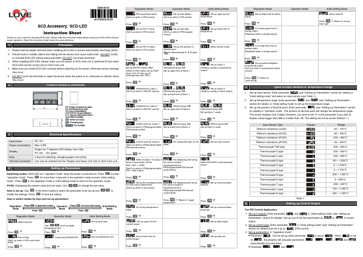
SCD Accessory: SCD-LED Instruction SheetThank you very much for choosing SCD-LED. Please read this instruction sheet before using your SCD-LED to ensure proper operation. Keep this instruction sheet handy for quick reference.1 Precaution1. Please hold the plastic terminal when installing SCD-LED to prevent electrostatic discharge (ESD).2. Prevent dust or metallic debris from falling into the device and cause malfunction. DO NOT modify or uninstall SCD-LED without being permitted. DO NOT use empty terminals.3. When installing SCD-LED, please make sure the power of SCD main unit is switched off and insertSCD-LED into the correct slot on SCD main unit.4. Make sure you install SCD-LED correctly before switching on the power; otherwise serious damagemay occur. 5. DO NOT touch the terminals or repair the device when the power is on; otherwise an electric shockmay occur.23Electrical SpecificationsInput power DC +5V Power consumption Max. 0.5WDisplay Single row 7-segment LED display, two 4 bitsPV: red SV: green Keys4 keys for selecting, changing pages and tuningTerminal connectionCan only be inserted into the “Display and Setup Unit” slot on SCD main unit4Setting up ParametersSwitching modes: SCD-LED is in ”operation mode” when the power is switched on, Pressto enter“regulation mode”. Pressfor more than 3 seconds in the operation mode to enter “initial setting mode”. Pressin the regulation mode or initial setting mode to return to the operation mode. PV/SV: Displaying the present value and set value. Use to change the set value.How to set up: Usein the three modes to select the parameter to be set up andtomodify the settings. Press to save the setting.How to switch modes by keys and set up parameters:temperature (SV) PressV A Control loop RUN/STOPSet up temperature unitSet up PID Ti valueSet up start stepSet up lower limit ofSet up PID Td valueSet up the position ofSelector or Set up output 1Hysteresis for output 1or Set up output 2Hysteresis for output 2Without group INBor Control cycle for output 1 Without group INBWithout group INBControl cycle for output 2For locking the keys on theSet up copy functionRatio of output 1 & output 2For displaying and tuningSet up the overlapped areaFor displaying and tuningtemperature” SetFor tuning temperatureSetSet up upper limit forSet up data lengthSet up lower limit forSet up parity bitinput type”For tuning upper limit ofFor tuning lower limit ofSet up positive/negative“auto-tuning”5 Types of Input Sensors & Temperature Range1. (see “Setting up Parameters” section for details) in2. (see “Setting up Parameters”3. (see “Setting up Parameters” section for details) in “operation mode”. The position of decimal point will change the temperature range.The screen displays only 4 digits; therefore, you have to set “0” in this parameter if you wish to display values bigger than 999 or smaller than -99. The setting will not be saved. Default = 1.Table 16Setting up Control OutputFor PID Control Application: 1. Set up 2 outputs: Enter parameter control output.2. Set up control type: Enter parameterin “initial setting mode” (see “Setting up Parameters”control.output.are set ashave to bedifferent.)For ON/OFF Control Application: 1.Set up 2 outputs: Enter parametercontroloutput.2.Set up control type: Enter parameter in “initial setting mode” (see “Setting up Parameters”control.at the same time.(heating), and outputFor Manual Control Application:1.Set up 2 outputs: Enter parametercontroloutput.2.Set up control type: Enter parameter in “initial setting mode” (see “Setting up Parameters”control.output.can be set up whensetoutput.1.Set up 2 outputs: Enter parametercontroloutput.2.Set up control type: Enter parameter in “initial setting mode” (see “Setting up Parameters”control.is set as “0”.output.are set ashave to be(in “operation mode"):For Proportional Output Application:1.Set up output function: Enter parameterin “initial setting mode” (see “Setting up Parameters”output.1.Set up upper limit: Enter parameterin “regulation mode” (see “Setting up Parameters” 2.Set up lower limit: Enter parameterin “regulation mode” (see “Setting up Parameters”section for details). Range: 0 ~ upper limit %.For Alarm Application:1.Set up output function (only when there is group INB): Enter parameterin “initial settingoutput. 2.Set up alarm type: Enter parameterINB) in “initialsetting mode”. See Table 2 for more details on the alarm output.Can be set up when there is no group INB.4. Set up delay alarm output: Enter parameterin “regulation mode” (unit: second). The alarmwill be enabled only when the temperature reaches the alarm output condition, and the conditionremains until the delay time is reached.SCD main unit offers 2 groups of alarm output, each with 12 alarm modes in the initial setting mode. When SV is higher or lower than SV, the alarm output will be enabled. See the table in the next column for the explanations on the 12 alarm output modes.Note: AL-H and AL-L include AL1H, AL2H and AL1L, AL2L.Table 27Setting up Communication1. Set up communication: Enter parameterin “initial setting mode” (see “Setting up Parameters” section for details) and select your desiredcommunication settings.2. SCD series temperature controller is able to set up or read communication settings throughSCD-LED.8Setting up Channel1. Selectchannel: Enter parameterin “regulation mode” (see “Setting up Parameters” sectionfor details) and select the channel to be monitored.2. How does it work: SCD main unit has maximum 8 channels which can be connected to 8 inputsensors at the same time. The 8 input channels belong to group INA and INB, each group with 4input channels. INB is optional accessory; therefore if INB is not inserted in SCD, SCD will onlyshow 4 channels.9 Setting up Copy Function1.Set up the function: Enter parameterin “initial setting mode” (see “Setting up Parameters”section for details) and select the function you desire.2. How does it work: The copy function allows a SCD main unit to copy its parameters (including thevalues set in the parameter and communication settings) to another SCD main unit throughSCD-LED. Follow the steps below:a.in “initial settingthecopy fails. Pressto return to “operation mode” and you will see the present temperature value (PV) and set temperature value (SV).b.on the screen, indicating that the writing-in isindicates the writing-in fails. Pressto return to “operation mode” andyou will see the present temperature value (PV) and set temperature value (SV).10Locking the Keys on Panel1. Lock the keys: Enter parameter in “operation mode” (see “Setting up Parameters” section2. How does it work:indicates that you canonly modify the set temperature value (SV), and all other functions are locked. 3. Press and at the same time to unlock the keys.11 Analog Output & Temperature Tuning1. Set up analog output tuning: Enter parameterin “regulation mode” (see2. Temperature offset tuning: Enter parameterin “regulation mode” and tune the parameter to the displayed temperature value.3. How does it work:a. Tuning analog output: For example, if you would like to have accurate 4 ~ 20mA of output, youmaking the meter point to 20mA.b. Tuning temperature offset: This allows the displayed temperature to plus or minus 1 offset value.12Error Message13 How to Install1 Remove all the terminal blocks on the panel.2 Uncover the panel and insert SCD-LED to the “operation interface” slot.3 Cover up the panel.4 Insert the terminal blocks back to theirpositions.。
轨道交通1500V 直流开关柜与钢轨电位限制装置

X市轨道交通工程1500V 直流开关柜与钢轨电位限制装置技术规格书年月目录一、技术条件 (1)1、适用范围 (1)2、环境条件 (1)3、采用标准 (1)4、系统参数 (2)5、技术要求及性能 (2)6、结构要求 (22)7、可靠性、可维护性、可扩展性 (28)8、铭牌及标识 (29)9、计划采用的主要元器件/原材料清单 (30)二、供货范围 (31)一、技术条件1、适用范围本技术规格书适用于X轨道交通工程供电系统设备中的1500V 直流开关柜及钢轨电位限制装置的技术要求。
2、环境条件装设地点:户内、户外(车辆段、停车场内钢轨电位限制装置)环境温度:-5℃~40℃相对湿度:日平均值不大于95%;月平均值不大于90%,有凝露情况发生。
海拔高度:≤1000 m地震烈度:≤6 度,设计基本地震加速度值为0.05g振动:f <10Hz 时,振幅为 0.3mm;10Hz <f < 150Hz 时,加速度为1m/s2。
雷暴日:>47 日/年3、采用标准设备的制造、试验和验收除了满足本技术规格书的要求外,还应符合如下标准:EN50123.1~7-2003 《Railway Applications - Fixed Installations - D.c.Switchgear》EN50124.1-1999 《铁路应用-绝缘配合-部分1:对绝缘和爬距的基本要求》IEC60146 《半导体变流器》IEC60439 《低压开关设备和控制设备组件》IEC60077 《电力牵引设备》IEC947 《低压开关设备和控制设备》IEC60068-2-30 《抗湿热环境能力》IEC60255-5 《电气继电器.第 5 部分:测量继电器和保护设备的绝缘配合要求和试验》GB/T14048.1-2012 《低压开关设备和控制设备总则》GB/T14048.2-2008 《低压开关设备和控制设备低压断路器》GB/T 7261-2008 《继电器及继电保护装置基本试验方法》GBT 25890.1~8-2010 《轨道交通地面装置直流开关设备》GB/T14598.13-2008(或I EC60255-22-1:2007)《电气继电器第22-1 部分:量度继电器和保护装置的电气干扰试验 1 MHz 脉冲群抗扰度试验》GB/T14598.14-2010(或I EC60255-22-2:1998)《电气继电器第22-2 部分:量度继电器和保护装置的电气干扰试验静电放电试验》GB/T14598.9-2010(或I EC60255-22-3:2002)《电气继电器第22-3 部分:量度继电器和保护装置的电气干扰试验辐射电磁场抗扰度》GB/T14598.10-2012《电气继电器第 22-4 部分:量度继电器和保护装置的电气干扰试验电快速瞬变/脉冲群抗扰度试验》开关柜及其组成部件应满足上述国内、国际标准的要求,且所采用的标准均为合同执行时的最新有效版本。
NPMPD 钢轨电位限制装置
A.1 概述 .............................................................................................................................................................. 5 A.1.1 文档目的.............................................................................................................................................. 5 A.1.2 保证...................................................................................................................................................... 5 A.1.3 文档信息.............................................................................................................................................. 5 A.1.4 资料复印件 .......................................................................................................................................... 5
ovpd(钢轨电位限制装置)

ovpd(钢轨电位限制装置)The function of the rail potential limiter in the DC traction power supply system and its coordination with the frame protection are analyzed, and the existing problems of the frame protection are discussed. The selection of main parameters of rail potential limiting device is put forward. After the thyristor contactor type rail potential limiting device is adopted, the voltage component is eliminated in the frame protection.Keywords metro; rail potential limiting device; frame protection;The traction power supply system of urban rail transit adopts DC1500V overhead catenary power supply, and the running rail is the return path. In order to reduce the stray current corrosion to the civil structure, steel bar, rail, equipment, metal shell and other underground metal pipelines, a more perfect stray current protection measure is adopted in the construction of rail transit. Namely, the DC traction power supply system is designed as ungrounded system. The DC power supply equipment is insulated and installed, and the rail is insulated with the ground through the insulation pad to reduce the leakage of stray current.When the power supply section of starting or running trains, or the occurrence of short circuit fault, because the rail as the pathway between the traction return and rail and the transition resistance, the rail on the real estate students suspended potential certain difference. A rail potential limiter (OVPD) is provided at each station and depot to preventdamage caused by excessive rail to ground potential. In order to meet the requirements of safe and reliable operation of the DC traction power supply system and the protection of passenger safety, it is necessary to select the equipment parameters of OVPD reasonably and consider the coordination relationship with other equipment.1OVPD operation characteristics and the reason of rail to ground potential rise1.1OVPD action characteristicsThe OVPD is installed at each station and parking area to monitor the voltage between the rail and the ground. If the voltage exceeds the setting value, the OVPD acts to short the rail to the ground. Meanwhile, the current flowing through the OVPD (between rail and ground) is monitored. When the current is lower than the setting value, the OVPD will automatically reset and disconnect the rail to ground.1.2 the main factors of rail to ground potential riseUnder normal running condition, when the train runs in the power supply section, the traction load current in the rail causes the rise of the rail to ground potential (positive or negative). The magnitude of the rail to ground potential is mainly related to the number of locomotives on the line, the load current, the distance between the traction stations and the transition resistance between the rails.When the following failure, caused by a steep rise in thepotential of rail and rail: catenary short-circuit; the catenary of overhead ground wire (ground) short-circuit fault; the DC equipment cabinet leakage fault; the traction substation rectifier transformer two side AC system single-phase earth.When the DC system fails, it is necessary to remove the fault or reduce the rail to ground potential in a short time, so as to ensure the safety of the personal and equipment.Characteristics of 2 frame protection deviceThe frame protection device is mainly used to start the corresponding circuit breaker trip when the positive pole of the DC equipment is short circuited to the outer shell of the equipment, and quickly cut down the fault and prevent the power supply equipment from being damaged. It is mainly composed of current and voltage measuring elements. One end of the current measuring element is connected with the outer shell of the equipment, and the other end is grounded for detecting the fault current flowing between the shell and the ground. The voltage measuring element is used to measure the voltage between the shell of the equipment and the negative pole of the DC device. One end is connected to the negative pole, the other end is connected with the outer shell of the equipment.When the positive electrode of any DC device is shorted to the outer shell, the grounding current flows through the current measuring element into the ground net, and then goes back to the rail (negative electrode) through the transition resistance between the rail and the ground (or drain cabinet). When the grounding current reaches the setting value, currentcomponent frame protection; and voltage measuring elements between the shell and the negative detection device, when the voltage is greater than the setting value, the voltage component in setting time, the AC and DC circuit breaker tripping the fault. The frame protector and the OVPD connection are shown in figure 1.Analysis of 3OVPD and frame protection action time and existing problems3.1 coordination of movement timeOVPD is mainly used to protect personal safety,The action should be able to meet the characteristics ofEN50122-1 (ProtectiveProvisionsRelatingtoElectricalSafetyandEarthing) human tolerance voltage - time curves of the requirements specified in the standards. As shown in table 1.When the train starts and runs normally, the rail ground potential rises. When the OVPD measures the rail ground potential over the setting value, the OVPD acts to short the rail to the ground. As shown in Figure 1, the voltage component measured by the OVPD and the frame is essentially the same voltage value. The frame protection should not act at this time. At present, the cooperation mode is the frame protection voltage component, the operation time setting value is longer than the OVPD operation time setting value (under the same measuring voltage condition), or the voltage setting value is higher than the OVPD.When the positive pole of the DC equipment is short circuited to the outer shell of the equipment, an instantaneous high voltage is detected by the OVPD and the frame protected voltage element. At this point, the frame protection should precede the OVPD action.Analysis of the existing problems of 3.2 frame protection(1) when rail is put into operation, the insulation performance of rail to ground is better. When the DC equipment of traction substation is out of frame leakage, the current in the current component is very small, and the frame protection current component does not move. When the voltage component detects that the voltage between the rail and the ground is greater than the setting value, the frame protection is performed within the set time, and the breaker is tripped at the AC and DC side of the rectifier unit. When a frame leakage occurs in a traction substation, the rail to ground potential will rise. That is, the protective voltage component of each traction substation will detect the higher voltage value between the negative pole and the ground and start the frame protection at the same time. Thus, the frame protection of the traction substation with no leakage of the frame causes misoperation and enlarges the scope of the accident power failure. When the overhead contact line is short circuited to the overhead earth wire, its operation is the same as that of the overhead contact line.(2) after running for a period of time, the insulation performance of rail to ground decreases and the transition resistance decreases. When the frame fails, the frameprotective current element can act reliably and act on the corresponding breaker trip. However, the potential difference between the rail and the ground is reduced, and when the setting value is too high, the frame protected voltage element does not move.(3) DC equipment frame leakage fault, no current flows through the current or small DC circuit breaker in the (adjacent to contribute, as in Figure 1, I1/2 I2/2), DC quick switch can not remove the fault in a short period of time, even if the DC circuit breaker can fast tripping, frame leakage fault has not removed. Only when the breaker on the AC side of the rectifier unit is tripped can the leakage of the frame be removed. Before the fault is removed, the voltage at both ends of the OVPD is the same as the voltage measured by the frame protection voltage element. If the OVPD cannot be closed within the required time, it may lead to an electrical shock wounding event. When the OVPD movement, forming a proximal pathway, a metal, the framework for the protection of current flowing through the element in the larger short-circuit current by short circuit OVPD, frame protection device capable of reliable operation, rapid removal of fault.When the catenary short-circuit of overhead ground wire, quick action OVPD and negative to overhead ground wire to form a metallic path through the feeder circuit breaker and overhead ground wire short circuit current is large, the current tripping the feeder circuit breaker, protection / timing and limiting current protection action quickly tripping fault.From the above analysis, it can be seen that the frameprotection voltage component has the possibility of maloperation and refusal in the actual use process. Sometimes, it can not only fail to protect the equipment, but also cause the expansion of the scope of the accident barrier. It is therefore recommended to cancel voltage components in frame protection.4OVPD electrical parameter analysis4.1OVPD typeThere are two main types of OVPD: contactor type and thyristor contactor type.Contactor type OVPD, when detecting that the rail potential value is higher than the setting value, the contactor moves the rail and ground short, and the operation time is about 150 to 200ms.Thyristor contactor OVPD is composed of two main circuits, thyristor circuit and contactor circuit. When the rail potential value is higher than the setting value, the thyristor is fast conducting, and simultaneously starts the contactor to move the rail and the grounding electrode short, so the operation time is very short (about 3MS).Selection of main parameters of 4.2 thyristor contactor type OVPD(1) maximum short-circuit current under OVPD;In the DC traction power supply system, the most serious condition for OVPD to withstand short circuit current is the leakage of the frame or the short-circuit of the contact wire and overhead ground wire. After the OVPD operation, the short-circuit current in the thyristor main circuit is the short-circuit current I supplied by the rectifier unit and the short-circuit current I1 and I2 supplied by the adjacent traction (shown in Figure 1). According to the calculation results (for the different capacity rectifier units and traction substation spacing, the current value will change), the main loop of thyristor changes in the current as shown in figure 2. Therefore, when selecting the OVPD, the ability of the OVPD to withstand short circuit currents should be able to meet the most severe short-circuit current without damage.(2) the time that the thyristor takesWhen a frame leakage fault occurs, the thyristor circuit is switched on and the frame protection current element measures the leakage current. From the start frame protection to the AC side circuit breaker and DC circuit breaker, the total trip time is about 120 to 170ms, while the contact time is about 150 to 200ms. Therefore, the duration of the thyristor circuit to withstand short circuit current should be the time after the OVPD thyristor circuit is switched on until the contactor circuit is switched on.5 Conclusion(1) when the DC equipment is out of frame leakage or the contact network and overhead ground wire are short circuited, in orderto ensure personal safety, the OVPD operation time should meet the requirements of EN50122-1 standard.(2) the worst condition of the OVPD device is the leakage of the frame or the short-circuit of the contact wire and the overhead ground wire. At this point, the OVPD has the largest short-circuit current and the longest duration, and the selected OVPD shall be able to withstand short-circuit currents in the most critical conditions without damage to the equipment.(3) the maximum short-circuit current value shall be calculated according to the power supply calculation, and the OVPD equipment shall be selected.(4) when the frame leakage fault or catenary and overhead ground wire short circuit fault, cause the entire rail (negative) and a steep rise in the potential difference, causing other traction frame element voltage protection misoperation, expansion of the scope of the accident. Therefore, after adopting thyristor contactor type OVPD, it is recommended that the voltage component be eliminated in the frame protection. Otherwise, it will only increase the trip times of the equipment, and then affect the normal operation of the traction system.。
SCD钢轨电位限制装置说明书

2.3
有关警告信息的解释 ..................................................... 7
2.4
安全规则 ............................................................... 7
2.5
电气危险源 ............................................................. 7
11.2.1 功能测试............................................................. 27
11.2.2 检测接触器触头....................................................... 27
11.3 修理 .................................................................. 27
2 安全.................................................................. 6
2.1
正确使用 ............................................................... 6
2.2
人员资格 ............................................................... 6
13.3 预整定值 .............................................................. 30
轨电位限制装置内部培训
17
K0 的工作电源为直流电源,是由整流元件把
220V交流电整流所得。在正常情况下,钢轨与大 地的电压差大于或等于整定值时,用作让钢轨与 大地接通,降下两者之间的电压差。
18
一端接钢轨,另一端经晶 闸模块与大地相连,动作 电流:80A、120A、 160A可调。
19
6.1发生以下情况时,指示灯“闭锁/复位”亮起: 1、U>合闸计数大于设定值; 2、U>>电压继电器动作; 3、U>>>电流继电器动作; 4、其他装置故障。 (如:接触器已闭合,仍然有 不安全电压存在;接触器位置故障;接触器分合闸 故障等。)
I
J K L M
接触器合位指示灯
可复位计数器 功能测试旋钮 加热器控制模式转换开关 不可复位计数器
12
编号
A B C
名称
U>>电压监测继电器 U>电压监测继电器 U<电压监测继电器 控制及监测电源空开 加热器电源空开 PLC 温湿度控制器 24V电源模块 中间继电器 接触器
A
B
C
D E F G
F DE I
22
6.1 U>测试:将测试转换开关快速转向U>测试并保持10s,“U>” 指示灯亮起,主触头闭合,“接触器合位”指示灯亮起,10s后主触 头自动断开。 6.2 U>三次闭锁功能:在主触头第一次自动断开后6s内,再次将测 试转换开关快速转向U>测试并保持10s使主触头再次闭合;在主触 头第二次自动断开后6s内,再次将测试转换开关快速转向U>测试并 保持10s使主触头再次闭合,此时“闭锁/复位”指示灯应亮起,主 触头不再自动断开; 6.3 U>>测试:将测试转换开关短暂转向U>>测试位置,“U>>” 指示灯亮起,主触头闭合,“接触器合位”指示灯亮起,“闭锁/复 位”指示灯亮起,按下复归按钮,主触头断开,面板故障指示灯熄灭; 6.4 U>>>测试:用细长螺丝批由下至上撬动电流继电器的辅助接点, 直流接触器闭合,“接触器合位”指示灯亮起,U>>>电压继电器动 作,“U>>>”指示灯亮起闭锁输出,“闭锁/复位”指示灯亮起;
地铁钢轨电位限制装置Ⅲ段频繁动作分析研究
地铁钢轨电位限制装置Ⅲ段频繁动作分析研究文章就某沿海城市地铁1号线部分车站的钢轨电位限制装置Ⅲ段频繁动作进行研究,从钢轨电位的影响因素分析,找出可能影响钢轨电位限制装置Ⅲ段频繁动作的原因,并提出相对应的治理措施。
标签:钢轨电位;钢轨电位限制装置;回流系统;暂态参数;功率分配Abstract:This paper studies the frequent movement of rail over-voltage protection device (OVPD)Ⅲsection in some stations of Metro Line 1 in a coastal city. From the analysis of the influencing factors of rail potential,the reasons that may affect the frequent movement of rail over-voltage protection device Ⅲsection are found out and the corresponding control measures are put forward.Keywords:rail potential;rail over-voltage protection device (OVPD);reflux system;transient parameters;power distribution1 概述目前国内各城市地铁均采用直流750V或1500V供电,电客车通过接触网或接触轨取流,牵引电流通过走行轨返回牵引变电所整流机组负极。
由于钢轨自身存在阻抗及杂散电流的影响,在钢轨上产生电压降落,即为钢轨电位。
钢轨电位的产生主要会造成以下3点危害:(1)危及乘客人身安全;(2)钢轨正向平均电位越高,杂散电流会越大,从而加快杂散电流对土建结构钢筋、设备金属外壳及地下金属管线产生腐蚀;(3)造成轨旁设备如屏蔽门、转辙机出现频繁打火放电现象,严重时可导致直流框架保护动作,引起大规模停电。
轨道交通1500V 直流开关柜与钢轨电位限制装置

X市轨道交通工程1500V 直流开关柜与钢轨电位限制装置技术规格书年月目录一、技术条件 (1)1、适用范围 (1)2、环境条件 (1)3、采用标准 (1)4、系统参数 (2)5、技术要求及性能 (2)6、结构要求 (22)7、可靠性、可维护性、可扩展性 (28)8、铭牌及标识 (29)9、计划采用的主要元器件/原材料清单 (30)二、供货范围 (31)一、技术条件1、适用范围本技术规格书适用于X轨道交通工程供电系统设备中的1500V 直流开关柜及钢轨电位限制装置的技术要求。
2、环境条件装设地点:户内、户外(车辆段、停车场内钢轨电位限制装置)环境温度:-5℃~40℃相对湿度:日平均值不大于95%;月平均值不大于90%,有凝露情况发生。
海拔高度:≤1000 m地震烈度:≤6 度,设计基本地震加速度值为0.05g振动:f <10Hz 时,振幅为 0.3mm;10Hz <f < 150Hz 时,加速度为1m/s2。
雷暴日:>47 日/年3、采用标准设备的制造、试验和验收除了满足本技术规格书的要求外,还应符合如下标准:EN50123.1~7-2003 《Railway Applications - Fixed Installations - D.c.Switchgear》EN50124.1-1999 《铁路应用-绝缘配合-部分1:对绝缘和爬距的基本要求》IEC60146 《半导体变流器》IEC60439 《低压开关设备和控制设备组件》IEC60077 《电力牵引设备》IEC947 《低压开关设备和控制设备》IEC60068-2-30 《抗湿热环境能力》IEC60255-5 《电气继电器.第 5 部分:测量继电器和保护设备的绝缘配合要求和试验》GB/T14048.1-2012 《低压开关设备和控制设备总则》GB/T14048.2-2008 《低压开关设备和控制设备低压断路器》GB/T 7261-2008 《继电器及继电保护装置基本试验方法》GBT 25890.1~8-2010 《轨道交通地面装置直流开关设备》GB/T14598.13-2008(或I EC60255-22-1:2007)《电气继电器第22-1 部分:量度继电器和保护装置的电气干扰试验 1 MHz 脉冲群抗扰度试验》GB/T14598.14-2010(或I EC60255-22-2:1998)《电气继电器第22-2 部分:量度继电器和保护装置的电气干扰试验静电放电试验》GB/T14598.9-2010(或I EC60255-22-3:2002)《电气继电器第22-3 部分:量度继电器和保护装置的电气干扰试验辐射电磁场抗扰度》GB/T14598.10-2012《电气继电器第 22-4 部分:量度继电器和保护装置的电气干扰试验电快速瞬变/脉冲群抗扰度试验》开关柜及其组成部件应满足上述国内、国际标准的要求,且所采用的标准均为合同执行时的最新有效版本。
地铁供电系统钢轨电位限制装置保护概述

地铁供电系统钢轨电位限制装置保护概述发表时间:2018-10-01T13:49:12.063Z 来源:《基层建设》2018年第26期作者:贾韬烈[导读] 摘要:在地铁直流牵引供电系统中,无论是接触轨式系统还是架空接触网式系统,均采用钢轨作为回流,而钢轨又存在泄漏电阻,因此,列车在供电区间内正常运行时,不可避免地造成钢轨对地电位的升高。
中铁电气化局集团第三工程有限公司河南郑州 450000摘要:在地铁直流牵引供电系统中,无论是接触轨式系统还是架空接触网式系统,均采用钢轨作为回流,而钢轨又存在泄漏电阻,因此,列车在供电区间内正常运行时,不可避免地造成钢轨对地电位的升高。
钢轨电位过高将对乘客的人身安全造成威胁,为此必须设置钢轨电位限制装置(OVPD)。
基于此种原因文章就地铁供电系统钢轨电位限制装置保护展开分析和探讨。
关键词:地铁供电系统;钢轨电位限制装置;保护引言由于在城市轨道交通的牵引供电直流系统中,直流设备和钢轨都是采用绝缘法安装,其作用是减少杂散电流的泄漏途径,减少杂散电流对钢轨、结构钢筋等金属体的电化学腐蚀,钢轨对地的绝缘电阻是随着绝缘材料的性能变化的,所以电流型框架保护的电流回路的电阻是不确定的,当电阻很大时,可能会造成电流回路检测值达不到整定值的要求,从而会发生设备绝缘下降时电流型框架保护未动作的情况,所以钢轨电位限制装置就是为了弥补这个缺陷,因此就需要研究地铁供电系统钢轨电位限制装置保护。
1钢轨电位限制装置工作原理钢轨电位限制装置主要由直流接触器、晶闸管、控制器等元器件组成,其原理示意图如图1所示。
钢轨电位限制装置一端连接变电所接地网,一端接到钢轨上,测量钢轨与地之间的电压。
当某供电区间无车时,在直流牵引系统正常工作的情况下,钢轨与地之间的电位为零。
当供电区间内有车运行或发生短路故障时,由于钢轨和地之间存在漏泄电阻的情况,钢轨电位迅速升高;当钢轨电位超过设定的阈值时,钢轨电位限制装置启动,短接钢轨与接地网使钢轨电位下降,从而保护车站旅客的人身安全。
香港地铁直流牵引供电系统钢轨电位限制装置的设计

香港地铁直流牵引供电系统钢轨电位限制装置的设计摘要:在香港地铁直流牵引供电系统中,钢轨对地绝缘安装,被用作直流牵引电流的负极回流通路。
为了保障乘客的安全,在钢轨和地之间安装了钢轨电位限制装置,当钢轨电位超过预定的值时,钢轨电位限制装置将钢轨电位钳制到地电位。
本文根据作者在香港地铁直流牵引供电系统设计中的实际经验,对钢轨电位限制装置的系统结构和设计原理进行介绍。
关键词:钢轨电位限制装置、晶闸管一、前言在香港地铁直流牵引供电系统中,钢轨对地绝缘安装,被用作直流牵引电流的负极回流通路。
因此,钢轨对地有时存在高电位,而列车与钢轨之间是等电位的,当乘客站在站台时,有可能通过列车车体接触到这一高电位。
特别是在站台上安装了站台屏蔽门之后,由于站台屏蔽门直接与钢轨连接,更增加了乘客接触钢轨高电位的机会。
为了保障乘客的安全,在钢轨或负母排和地之间安装了钢轨电位限制装置。
二、系统构成及装置特性钢轨电位限制装置安装在牵引变电所和车站内,用来将钢轨的电位限制在预定的范围内。
同时,在接触导线对故障电流回流线或地短路时,钢轨电位限制装置还可提供故障电流的回流通路,使得相应的直流馈线断路器可以识别故障并快速分断以清除故障。
系统构成如图一所示。
图一系统构成钢轨电位限制装置监视钢轨与地之间的电压,如果该电压超过预定的值,钢轨电位限制装置动作,将钢轨通过钢轨电位限制装置接地,同时,钢轨电位限制装置监视钢轨与地之间的电流,当该电流低于预定的值时,钢轨电位限制装置将自动复位,断开钢轨对地的连接。
在香港地铁工程中,钢轨电位限制装置的设计主要采用了晶闸管加接触器的技术,如图一所示。
在钢轨对地方向和地对钢轨方向设置两组晶闸管,利用电压检测电路和触发脉冲电路来产生触发脉冲和控制信号去触发两组晶闸管的导通以及控制接触器的闭合。
通过控制电路来调节预定的电压值和相应的延时时间。
通过电流检测电路,当电流低于预定值时使钢轨电位限制装置自动复位,电流值也可以在一定范围内进行设置。
轨电位限制装置txf1
昌平线NPMPD型钢轨电位限制装置一、概述在直流牵引系统中,由于操作电流和短路电流的存在,可能会引起回流回路和大地间产生超过安全许可的接触电压。
在此情况下,就需要在回流回路与大地间装设一套钢轨电位限制装置,以限制运行轨电位,避免超出安全许可的接触电压的发生(此安全电压的规定参照欧洲EN标准)。
当发生超出安全许可的接触电压时,此钢轨电位限制装置就将钢轨与大地快速短接,从而保证人员和设施的安全。
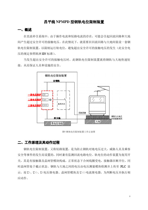
自钢轨一段电压保护二段电压保护三段电压保护至大地图1 钢轨电位限制装置工作示意图二、工作原理及其动作过程钢轨电位限制装置,又称短路装置,是为防止钢轨对地电压过大,威胁人员及乘客安全等事件的发生而设置的,同时兼有监测回流电路电位。
轨电位的动作装置为复用开关,其是有接触器及晶闸管模块构成,正常状态下合闸线圈受电,接触器在断开位,同时晶闸管处于截止状态。
钢轨与大地之间的电压由电压测量模块检测并上传至PLC显示,而U>、U>>、U<电压继电器、晶闸管模块及U>>>电流继电器,为判断电压并执行相应动作。
钢轨电位限制装置不断监测钢轨对大地的电位:1.当电位差大于设定电压的U>值(90V)时经0.8s延时后,合闸线圈失电,接触器合闸,同时柜体面板上的U>指示灯亮起,走行轨与大地短接,经过10s延时且短路电流小于设定值时,线圈得电,接触器复归。
在60s内发生3次U>动作,接触器将合闸并闭锁,同时面板上的闭锁指示灯亮起,可以就地或远方复归。
2.当电位差大于设定电压的U>>值(150V)时,无延时,合闸线圈失电,接触器合闸并闭锁,同时柜体面板上的U>>指示灯及闭锁指示灯亮起,走行轨与大地短接,且不会延时复归,需就地或远方复归。
3.当电位差大于设定电压的U>>>值(600V)时,无延时,晶闸管回路首先导通使钢轨与大地短路,然后电流继电器动作,使合闸线圈失电,接触器合闸并闭锁,此时晶闸管回路立即断开,同时柜体面板上的U>>>指示灯及闭锁指示灯亮起,U>>>无法远方复归,只能打开高压室门按动电流继电器上的红色复归按钮及面板上的复位按钮,钢轨电位装置才能恢复正常运行。
- 1、下载文档前请自行甄别文档内容的完整性,平台不提供额外的编辑、内容补充、找答案等附加服务。
- 2、"仅部分预览"的文档,不可在线预览部分如存在完整性等问题,可反馈申请退款(可完整预览的文档不适用该条件!)。
- 3、如文档侵犯您的权益,请联系客服反馈,我们会尽快为您处理(人工客服工作时间:9:00-18:30)。
13.3 预整定值 .............................................................. 30
13.4 特性 .................................................................. 30
SITRAS® SCD MFZ 80
用于直流牵引系统的钢轨电位限制装置
安装、操作、维护说明书
版本:1.26
西门子交通技术集团 铁路电气化部
订货号: A52811-C2721-D012-21-7619 Copyright © Siemens AG 2007. 版权所有
西门子交通技术 让运动的世界更具活力
9.6
功能测试 .............................................................. 24
10 故障检修 ............................................................. 26
11 维护................................................................. 27
5.1.5 控制电源故障......................................................... 12
5.1.6 钢轨电位限制装置故障检测............................................. 12
5.1.7 接触器故障........................................................... 13
11.1 维护服务 .............................................................. 27
11.2 检测 .................................................................. 27
5.1.2 电压大于或等于 U> .................................................... 12
5.1.3 电压大于或等于 U >> .................................................. 12
5.1.4 电压大于或等于 U >>> ................................................. 12
2/31
SCDT_OI_23_C.doc
目录
交通技术集团
1 一般性说明 ............................................................ 5
所用图示的介绍.................................................................. 5
7.1
规定/前提条件 ......................................................... 15
7.2
安装/就位 ............................................................. 15
7.2.1 安装 SITRAS® SCD 装置 ................................................. 15
8 调试................................................................. 18
8.1
规则/前提条件 ......................................................... 18
SCDT_OI_26_C
该产品的产权所有人西门子交通技术集团铁路电气化部引入并执行了符合 DIN EN ISO 9001 质量管理体系 质量保证模型 设计、开发、生产、安装和维护的QM说明 的质量管理体系。
早在1994年就获得了由DQS (Deutsche Gesellschaft zur Zertifi-zierung von Managementsystemen mbH)签发的证书。
11.2.1 功能测试............................................................. 27
11.2.2 检测接触器触头....................................................... 27
11.3 修理 .................................................................. 27
13 技术数据 ............................................................. 29
13.1 机械数据 .............................................................. 29
13.2 电气数据 .............................................................. 29
如果您需要这些安装说明的副本,请向有关的西门子销售部订购。
发行者: 西门子交通技术集团 铁路电气化部 邮政信箱: 3240 D-91050 Erlangen 有权未经通知予以修改! © Siemens AG 2007
注意 未经明确的书面许可,禁止复制、传输或 使用本文件及其内容。违犯者对损失负责。 保留所有版权,包括专利授予权和有效模 型或设计的注册权
3 目的和使用 ............................................................ 8
4 设计.................................................................. 9
4.1
产品介绍 ............................................................... 9
4.2
结构和组成元件 ......................................................... 9
4.2.1 SITRAS® SCD 设计结构................................................... 9
4.2.2 组成元件............................................................. 10
2.3
有关警告信息的解释 ..................................................... 7
2.4
安全规则 ............................................................... 7
2.5
电气危险源 ............................................................. 7
6 运输和储存 ........................................................... 14
6.1
运输条件 .............................................................. 14
6.2
包装 .................................................................. 14
9.3
LOGO!控制器调整 ....................................................... 19
9.4
闭锁后复位 ............................................................ 20
9.5
重设控制器 ............................................................ 21
9 操作................................................................. 19
9.1
规则/前提条件 ......................................................... 19
9.2
显示、指示器 .......................................................... 19
2 安全.................................................................. 6
2.1
正确使用 ............................................................... 6
2.2
人员资格 ............................................................... 6
12 拆解、废弃和回收 ..................................................... 27
